3070 offshore center console owner’s … offshore 3070 offshore center console owner’s manual...
TRANSCRIPT

3070 OFFSHORE
3070 OFFSHORECENTER CONSOLE
OWNER’S MANUAL
FISHING BOATS3901 St. Lucie Blvd.
Ft. Pierce, Florida 34946
Print Date 1/2003

3070 OFFSHORE
THIS PAGE WAS LEFT BLANKINTENTIONALLY

3070 OFFSHORE i
SAFETY INFORMATION
Your 3070 Offshore Owner’s Manual hasbeen written to include a number of safety instructions toassure the safe operation and maintenance of your boat. Theseinstructions are in the form of DANGER, WARNING,CAUTION, and NOTICE statements. The followingdefinitions apply:
IMMEDIATE HAZARDS WHICH WILL RESULT INSEVERE PERSONAL INJURY OR DEATH.
HAZARDS OR UNSAFE PRACTICES WHICH COULDRESULT IN SEVERE PERSONAL INJURY OR DEATH.
HAZARDS OR UNSAFE PRACTICES WHICH COULDRESULT IN MINOR PERSONAL INJURY OR PRODUCTAND PROPERTY DAMAGE.
INFORMATION WHICH IS IMPORTANT TO PROPEROPERATION OR MAINTENANCE, BUT IS NOT HAZARDRELATED.
All instructions given in this book are as seen from the sternlooking toward the bow, with starboard being to your right,and port to your left. A glossary of boating terms is included.
IMPORTANT NOTE: Your boat uses internal combustionengines and flammable fuel. Every precaution has been takenby Pursuit Fishing Boats to reduce the risks associated withpossible injury and damage from fire or explosion, but yourown precaution and good maintenance procedures are neces-sary in order to enjoy safe operation of your boat.
NOTICE

3070 OFFSHORE
THIS PAGE WAS LEFT BLANKINTENTIONALLY

3070 OFFSHORE ii
BOAT INFORMATION
Please fill out the following information section and leave it in your Pursuit3070 Offshore Owner’s Manual. This information will be important for youand Pursuit service personnel to know, if and when you may need to callPursuit for technical assistance or service.
MAKE:
SERIAL #:
MODEL:
KW:
PHONE:
REPRESENTATIVE:
GENERATOR
NAME:
DEALER/PHONE:
ADDRESS:
SERVICE MANAGER:
ADDRESS:
SALESMAN:
DEALER PURSUIT
MODEL:
PURCHASE DATE:
IGNITION KEYS #:
DRAFT:
HULL SERIAL #:
DELIVERY DATE:
REGISTRATION #:
WEIGHT:
TRANSMISSION(S) (Inboard)
OUTDRIVE(S) (Inboard/Outboard)
MAKE:
PORT SERIAL #:
MODEL:
STARBOARD SERIAL #:
PORT SERIAL #:
MAKE: MODEL:
STARBOARD SERIAL #:
PROPELLER(S)
MAKE: MODEL:
STARBOARD SERIAL #:
MAKE:
DIAMETER/PITCH:
PORT SERIAL #:
RATIO:
ENGINE(S)
BLADES:
OTHER:
BOAT
Pursuit Fishing Boats reserves the right to make changes and improvements in equipment, design and vendoredequipment items, at any time without notification.

3070 OFFSHORE
THIS PAGE WAS LEFT BLANKINTENTIONALLY

3070 OFFSHORE
Warranty and Warranty Registration CardsThe Pursuit Limited Warranty Statement is included with your boat. It has been written to be clearlystated and easily understood. If you have any questions after reading the warranty, please contactthe Pursuit Customer Relations Department.
Pursuit, engine manufacturers, and the suppliers of major components maintain their ownmanufacturer's warranty and service facilities. It is important that you properly complete thewarranty registration cards included with your boat and engine(s) and mail them back to themanufacturers to register your ownership. This should be done within 15 days of the date ofpurchase and before the boat is put into service. A form for recording this information is providedat the beginning of this manual. This information will be important for you and service personnelto know, if and when you may need service or technical information.
The boat warranty registration requires the Hull Identification Number “HIN” which is locatedon the starboard side of the transom, just below the rubrail. The engine warranty registrationrequires the engine serial number(s). Please refer to the engine owner's manual for the location ofthe serial number(s).
IMPORTANT:All boat manufacturers are required by the Federal Boat Safety Act of 1971 to notify first timeowners in the event any defect is discovered “which creates a substantial risk of personal injury tothe public.” It is essential that we have your warranty registration card complete with yourname and mailing address in our files so that we can comply with the law if it should becomenecessary.
Product ChangesPursuit is committed to the continuous improvement of our boats. As a result, some of theequipment described in this manual or pictured in the catalog may change or no longer be available.Pursuit reserves the right to change standard equipment, optional equipment and specifi-cations without notice or obligation. If you have questions about the equipment on your Pursuit,please contact the Pursuit Customer Relations Department.
Transferring The WarrantyFor a Transfer fee, S2 Yachts will extend warranty coverage to subsequent owners of Pursuitmodels for the duration of the original warranty period. Please refer to the Pursuit Limited WarrantyStatement for the procedure to transfer the warranty.
To take advantage of this program, notification of the change of ownership, including the newowner's name, address and telephone number together with the appropriate fee, must be sent toPursuit Fishing Boats, Customer Relations Department, 3901 St. Lucie Boulevard, Ft. Pierce,Florida 34946, within 30 days of the date of resale.
IMPORTANT INFORMATION
iii

3070 OFFSHORE
S2 Yachts will confirm, in writing, that the transfer of the warranty has taken place. After which,the transferee will be treated as the original purchaser as outlined in the Pursuit Limited WarrantyStatement.
ServiceAll warranty repairs must be performed by an authorized Pursuit Dealer. Should a problem developthat is related to faulty workmanship or materials, as stated in the Limited Warranty, you shouldcontact your Pursuit dealer to arrange for the necessary repair. If you are not near your dealer oranother authorized Pursuit dealer or the dealer fails to remedy the cause of the problem, then contactthe Pursuit Customer Relations Department within 15 days. It is the boat owner's responsibilityto deliver the boat to the dealer for warranty service.
iv

3070 OFFSHORE
Registration and NumberingFederal law requires that all undocumented vessels equipped with propulsion machinery beregistered in the state of principal use. A certificate of number will be issued upon registering theboat. These numbers must be displayed on your boat. The owner/operator of a boat must carrya valid certificate of number whenever the boat is in use. When moved to a new state of principaluse, the certificate is valid for 60 days.
In order to be valid, the numbers must be installed to the proper specifications. Check with yourdealer or state boating authority for numbering requirements. The Coast Guard issues the certificateof number in Alaska; all others are issued by the state.
InsuranceIn most states the boat owner is legally responsible for damages or injuries he or someone elseoperating the boat causes. Responsible boaters carry adequate liability and property damageinsurance for their boat. You should also protect the boat against physical damage and theft. Somestates have laws requiring minimum insurance coverage. Contact your dealer or state boatingauthority for information on the insurance requirements in your boating area.
Reporting Boating AccidentsAll boating accidents must be reported by the operator or owner of the boat to the proper marinelaw enforcement authority for the state in which the accident occurred. Immediate notification isrequired if a person dies or disappears as a result of a recreational boating accident.
If a person dies or there are injuries requiring more than first aid, a formal report must be filed within48 hours.
A formal report must be made within 10 days for accidents involving more than $500.00 damageor the complete loss of a boat.
A "Boating Accident Report" form is located near the back of this manual to assist you in reportingan accident. If you need additional information regarding accident reporting, please call theBoating Safety Hotline, 800-368-5647.
EducationIf you are not an experienced boater, we recommend that the boat operator and other people thatnormally accompanies the operator, enroll in a boating safety course. Organizations such as theU.S. Power Squadrons, United States Coast Guard Auxiliary, State Boating Authorities and theAmerican Red Cross offer excellent boating educational programs. These courses are worthwhileeven for experienced boaters to sharpen your skills or bring you up to date on current rules and
OWNER'S/OPERATOR'SRESPONSIBILITIES
v

3070 OFFSHORE
regulations. They can also help in providing local navigational information when moving to a newboating area. Contact your dealer, State Boating Authority or the Boating Safety Hotline, 800-368-5647 for further information on boating safety courses.
Required EquipmentU.S. Coast Guard regulations require certain equipment on each boat. The Coast Guard also setsminimum safety standards for vessels and associated equipment. To meet these standards some ofthe equipment must be Coast Guard approved. “Coast Guard Approved Equipment” has beendetermined to be in compliance with USCG specifications and regulations relating to performance,construction, or materials. The equipment requirements vary according to the length, type of boat,and the propulsion system. Some of the Coast Guard equipment is described in the SafetyEquipment chapter of this manual. For a more detailed description, obtain “Federal RequirementsAnd Safety Tips For Recreational Boats” by contacting the Boating Safety Hotline 800-368-5647or your local marine dealer or retailer and read the book “Sportfish, Cruisers, Yachts - Owner'sManual,” included with this manual.
Some state and local agencies impose similar equipment requirements on waters that do not fallunder Coast Guard jurisdiction. These agencies may also require additional equipment that is notrequired by the Coast Guard. Your dealer or local boating authority can provide you with additionalinformation for the equipment requirements for your boating area.
vi

3070 OFFSHORE
TABLE OF CONTENTS
Chapter 1: Propulsion SystemPage
1.1 General ................................................................................ 1-11.2 Drive System Corrosion ....................................................... 1-21.3 Engine Lubrication ................................................................ 1-21.4 Engine Cooling System ......................................................... 1-31.5 Propellers ............................................................................ 1-31.6 Engine Instrumentation .......................................................... 1-4
Chapter 2: Helm Control Systems
2.1 General ................................................................................. 2-12.2 Engine Throttle and Shift Controls .......................................... 2-12.3 Neutral Safety Switch ............................................................ 2-22.4 Engine Power Tilt and Trim .................................................... 2-22.5 Engine Stop Switch ................................................................ 2-32.6 Steering System ..................................................................... 2-42.7 Trim Tabs .............................................................................. 2-42.8 Control Systems Maintenance ................................................ 2-5
Chapter 3: Fuel System
3.1 General ................................................................................. 3-13.2 Outboard Fuel System ........................................................... 3-33.3 Diesel Generator Fuel System ................................................ 3-43.4 Fueling Instructions ................................................................ 3-53.5 Fuel System Maintenance ...................................................... 3-7
Chapter 4: Electrical System
4.1 General ................................................................................. 4-14.2 12-Volt System ..................................................................... 4-1
vii

3070 OFFSHORE
TABLE OF CONTENTS
Chapter 4: Electrical System (Cont.)Page
4.3 110-Volt System ................................................................... 4-94.4 Electrical System Maintenance ............................................... 4-13
Chapter 5: Freshwater System
5.1 General ................................................................................. 5-15.2 Freshwater System Operation ................................................ 5-15.3 Water Heater ........................................................................ 5-25.4 Shore Water Connection ....................................................... 5-25.5 Shower Operation ................................................................. 5-35.6 Freshwater System Maintenance ............................................ 5-3
Chapter 6: Raw Water System
6.1 General ................................................................................. 6-16.2 High Pressure Washdown ...................................................... 6-16.3 Livewell ................................................................................. 6-26.4 Air Conditioning Pump........................................................... 6-36.5 Raw Water System Maintenance ........................................... 6-4
Chapter 7: Drainage Systems
7.1 General ................................................................................. 7-17.2 Cockpit Drains ...................................................................... 7-17.3 Hard-Top Drains ................................................................... 7-17.4 Bilge Drainage ....................................................................... 7-27.5 Fishbox, Cooler and Storage Compartment Drains ................. 7-37.6 Water System Drains ............................................................. 7-37.7 Cabin Drains ......................................................................... 7-3
viii

3070 OFFSHORE
TABLE OF CONTENTS
Chapter 7: Drainage Systems (Cont.)Page
7.8 Rope Locker Drains .............................................................. 7-47.9 Drainage System Maintenance ............................................... 7-4
Chapter 8: Ventilation System
8.1 Cabin Ventilation .................................................................. 8-18.2 Windshield Ventilation ........................................................... 8-18.3 Carbon Monoxide and Proper Ventilation ............................. 8-28.4 Bilge Compartment Ventilation .............................................. 8-28.5 Maintenance ......................................................................... 8-2
Chapter 9: Exterior Equipment
9.1 Deck ................................................................................... 9-19.2 Hull ...................................................................................... 9-39.3 Cockpit ............................................................................... 9-4
Chapter 10: Interior Equipment
10.1 Marine Head System............................................................ 10-110.2 Refrigerator .......................................................................... 10-310.3 Air Conditioner .................................................................... 10-310.4 Galley and Sink .................................................................... 10-410.5 Carbon Monoxide Detector ................................................. 10-510.6 Convertible V-Berth and Table ............................................. 10-5
ix
3070 OFFSHORE
TABLE OF CONTENTS
Chapter 11: Safety Equipment
11.1 General ................................................................................. 11-111.2 Engine Alarms ....................................................................... 11-111.3 Neutral Safety Switch ........................................................... 11-211.4 Engine Stop Switch ............................................................... 11-211.5 Required Safety Equipment ................................................... 11-211.6 Carbon Monoxide ................................................................ 11-511.7 First Aid ............................................................................... 11-811.8 Additional Safety Equipment ................................................. 11-9
Chapter 12: Operation
12.1 General ................................................................................ 12-112.2 Rules of the Road ................................................................. 12-112.3 Pre-Cruise Check ................................................................ 12-312.4 Operating Your Boat ............................................................ 12-412.5 Tower Operation ................................................................. 12-712.6 Fishing ................................................................................. 12-812.7 Grounding and Towing ......................................................... 12-812.8 Transporting Your Boat ........................................................ 12-9
Chapter 13: Routine Maintenance
13.1 Exterior Hull and Deck ......................................................... 13-113.2 Upholstery, Canvas and Enclosures ...................................... 13-413.3 Cabin Interior ....................................................................... 13-613.4 Bilge and Generator ............................................................. 13-713.5 Drainage System .................................................................. 13-8
x
Page

3070 OFFSHORE
TABLE OF CONTENTS
Chapter 14: Seasonal MaintenancePage
14.1 Storage and Lay-up ............................................................. 14-114.2 Winterizing ........................................................................... 14-414.3 Recommissioning .................................................................. 14-7
Chapter 15: Schematics
DC Wiring Schematic ..................................................................... 15-1AC Wiring Schematic ..................................................................... 15-2Rod Locker Hatch Lifter Switch ..................................................... 15-3Battery Cable Routing ..................................................................... 15-4Hydraulic Steering System .............................................................. 15-5Control Cables ............................................................................... 15-6Generator ....................................................................................... 15-7Fuel System 2-Stroke ..................................................................... 15-8Fuel System 4-Stroke ..................................................................... 15-9Fuel Selector Valves ....................................................................... 15-10Freshwater System ......................................................................... 15-11Raw Water System......................................................................... 15-12Drainage System............................................................................. 15-13Sump Pump Drain System .............................................................. 15-14Air Conditioning System ................................................................. 15-15Sling Positions ................................................................................ 15-16Bunk Locations .............................................................................. 15-17Half Tower Plate Locations ............................................................. 15-18
Appendix A: Glossary of Terms ........................................................... A-1
Appendix B: Maintenance Log ............................................................. B-1
Appendix C: Boating Accident Report .................................................. C-1
xi

3070 OFFSHORE
THIS PAGE WAS LEFT BLANKINTENTIONALLY

3070 OFFSHORE
Chapter 1:
PROPULSION SYSTEM
1.1 General
The Pursuit 3070 Offshore is designed to be powered with twin 2-cycle or 4-cycle outboard motors.
Each manufacturer of the various outboard motors provides an owner’s information manual withits product. It is important that you read the manual(s) very carefully and become familiar with theproper care and operation of the engine and drive system. A warranty registration card has beenfurnished with each new engine and can be located in the engine owner’s manual. All informationrequested on this card should be filled out completely by the dealer and purchaser and then returnedto the respective engine manufacturer as soon as possible.
DO NOT ATTEMPT TO SERVICE ANY ENGINE OR DRIVE COMPONENTWITHOUT BEING TOTALLY FAMILIAR WITH THE SAFE AND PROPERSERVICE PROCEDURES. CERTAIN MOVING PARTS ARE EXPOSED ANDCAN BE DANGEROUS TO SOMEONE UNFAMILIAR WITH THE OPERATIONAND FUNCTION OF THE EQUIPMENT.
3070 Offshore
1-1
3070 OFFSHORE
DO NOT INHALE EXHAUST FUMES! EXHAUST CONTAINS CARBON MON-OXIDE THAT IS COLORLESS AND ODORLESS. CARBON MONOXIDE IS ADANGEROUS GAS THAT IS POTENTIALLY LETHAL.
1.2 Drive System Corrosion
Each outboard motor is a complete drive system with the gear case being just forward of thepropeller and connected to the power head with a vertical drive shaft. Other than the routinemaintenance outlined in the engine owner’s manual, there is little to be concerned with unless theboat is to be kept in saltwater for extended periods of time. Then the main concerns are marinegrowth and galvanic corrosion.
Marine growth occurs when components are left in the water for extended periods and can causepoor performance or permanent damage to the exposed components. The type of growth and howquickly it occurs is relative to the water conditions in your boating area. Water temperature,pollution, current, etc. can have an effect on marine growth.
Galvanic corrosion is the corrosion process occurring when different metals are submerged in anelectrolyte. Sea water is an electrolyte and submerged engine components must be properlyprotected. Outboard motors are equipped with sacrificial anodes to prevent galvanic corrosionproblems. The anodes must be monitored and replaced as necessary. For locations andmaintenance, please refer to the engine owner’s manual.
When leaving the boat in the water, tilt the motors as high as possible. This will decrease the riskof marine growth around the cooling inlets, propeller and exhaust ports and damage from galvaniccorrosion.
DO NOT PAINT THE OUTBOARD MOTORS WITH ANTIFOULING PAINTSDESIGNED FOR BOAT HULLS. MANY OF THESE PAINTS CAN CAUSE SE-VERE DAMAGE TO THE ENGINES. CONTACT YOUR PURSUIT DEALEROR ENGINE MANUFACTURER FOR INFORMATION ON THE PROPERPAINTING PROCEDURES.
1.3 Engine Lubrication
2-cycle outboard motors are lubricated by a variable ratio oil injection system. The oil tanks aremounted below the stern bait station near the transom. Always monitor the oil level before eachcruise by checking the gauge in the helm or visually checking the oil level using the reference markson the tanks. When additional oil is needed, use only the type of oil specified by the enginemanufacturer. Refer to the engine owner’s manual for oil specifications and additional informationon the oil injection system.
1-2

3070 OFFSHORE
4-cycle outboard engines have an oil sump in the crankcase that must be kept full of the type andgrade of oil recommended by the engine manufacturer. It is normal for 4-cycle engines to consumea small amount of oil. Therefore, the oil must be checked before each use and changed at regularintervals as instructed by the engine owner's manual. As with 2-cycle engines, use only the typeof oil specified by the engine manufacturer.
Note: Always monitor the oil level in the tanks and only use the type of oil specified by theengine manufacturer.
1.4 Engine Cooling System
Outboard engines are raw water (sea water) cooled. Water is pumped through the water inlets,circulated through the engine block, and relinquished with the exhaust gases through the propellerhub. The water pump uses a small impeller made of synthetic rubber. The impeller and water pumpcannot run dry for more than a few seconds. In most outboard motors, some cooling water isdiverted through ports below the engine cowling. This allows the operator to visually check theoperation of the cooling system. When the engine is started, always check for a steady stream ofwater coming out of those ports.
NEVER RUN AN OUTBOARD MOTOR WITHOUT WATER FLOWING TOTHE WATER PUMP. SERIOUS DAMAGE TO THE WATER IMPELLER ORENGINE COULD RESULT.
Note: If the boat is used in salt or badly polluted water, the engines should be flushed aftereach use. Refer to the engine owner’s manual for the proper engine flushingprocedure.
1.5 Propellers
The propellers convert the engine’s power into thrust. They come in a variety of styles, diametersand pitches. The one that will best suit the needs of your Pursuit will depend somewhat on yourapplication and expected average load. Propeller sizes are identified by two numbers stamped onthe prop in sequence. The 1st number in the sequence (example 14 x 21) is the diameter of thepropeller, and the 2nd number is the pitch. Pitch is the theoretical distance traveled by the propellerin each revolution. Always repair or replace a propeller immediately if it has been damaged. Adamaged and therefore out of balance propeller can cause vibration that can be felt in the boat andcould damage the engine gear assembly. Refer to the engine owner’s manual for information onpropeller removal and installation.
1-3

3070 OFFSHORE
RUNNING AGROUND OR STRIKING AN UNDERWATER OBSTRUCTION CANRESULT IN SERIOUS INJURY TO PASSENGERS AND DAMAGE TO THEMOTOR OR BOAT. IF YOUR BOAT RUNS AGROUND, EVALUATE THEDAMAGE THEN PROCEED AT LOW SPEED TO THE NEAREST SERVICEFACILITY AND HAVE AN IMMEDIATE INSPECTION MADE BEFORE FUR-THER USE OF THE CRAFT. A DAMAGED BOAT CAN TAKE ON WATER.KEEP ALL LIFE SAVING DEVICES CLOSE AT HAND WHILE DRIVING TOA DOCK AREA. IF THE BOAT CANNOT BE IMMEDIATELY REMOVEDFROM THE WATER, THOROUGHLY INSPECT THE BILGE AREA FORLEAKS SO THAT THE BOAT DOES NOT SINK WHILE MOORED.
1.6 Engine Instrumentation
The helm station is equipped with a set of engine instruments and/or alarms. These instrumentsallow the pilot to monitor the engines’ operational conditions. Close observation of theseinstruments allows the pilot to operate the engines at the most efficient level and could save themfrom serious costly damage. The instrumentation is unique to the type of outboard motors installedon your Pursuit. Some or all of the following gauges may be present.
TachometerThe tachometer displays the speed of the engine in revolutions per minute (RPM). This speed isnot the boat speed or necessarily the speed of the propeller. The tachometer may not register zerowith the key in the “OFF” position.
NEVER EXCEED THE MAXIMUM RECOMMENDED OPERATION RPM OFTHE ENGINE. MAINTAINING MAXIMUM, OR CLOSE TO MAXIMUM RPMFOR EXTENDED PERIODS CAN REDUCE THE LIFE OF THE ENGINE.
SpeedometerThe speedometer indicates the speed of the boat in miles per hour. Most speedometers measure thewater pressure against a small hole in a pickup tube located in the engine lower unit or mountedon the bottom of the transom.
Temperature WarningThe temperature warning indicates the temperature of the engine. A sudden increase in thetemperature could indicate an obstructed water inlet or an impeller failure.
1-4
Helm
CONTINUED OPERATION OF AN OVERHEATED ENGINE CAN RESULT INENGINE SEIZURE. IF AN UNUSUALLY HIGH TEMPERATURE READINGOCCURS, SHUT THE ENGINE OFF IMMEDIATELY. THEN INVESTIGATEAND CORRECT THE PROBLEM.
3070 OFFSHORE 1-5
Fuel GaugeThe fuel gauge indicates the amount of fuel in the fuel tanks. The fuel gauge switch, located onthe helm, is used to switch the gauge reading to the port or starboard fuel tank.
VoltmeterThe voltmeter displays the voltage for the battery and the charging system. The normal voltage is11 to 12 volts with the engines off and 13 to 14.5 volts with the engine(s) running.
Hour MeterThe hour meter keeps a record of the operating time for the engine.
Tilt/Trim GaugeThe tilt/trim gauge monitors the position of the outboard engine. The upper range of the gaugeindicates the tilt, which is used for trailering and shallow water operation. The lower range indicatesthe trim position. This is the range used to adjust the hull angle while operating your boat on plane.Please refer the engine owner’s manual for more information on the operation of the outboardpower tilt and trim.
Engine AlarmsMost outboards are equipped with an audible alarm system mounted in the helm area that monitorsselected critical engine systems. The alarm will sound if one of these systems begins to fail. Referto the engine owner’s manual for information on the alarms installed with your engines.
IF THE ENGINE ALARM SOUNDS, IMMEDIATELY SHUT OFF THE ENGINEUNTIL THE PROBLEM IS FOUND AND CORRECTED.
Fuel ManagementFuel management systems are standard equipment with some outboard engines. On Yamaha®
engines, the fuel management gauge is a multifunction gauge used to monitor the gallons per hour,miles per gallon, total gallons used and engine synchronization. If you have a fuel managementsystem installed on your boat, please refer to the engine or fuel management manual for informationon that system.
Depth GaugeThe depth gauge indicates the depth of the water below the bottom of the boat.

3070 OFFSHORE1-6
CompassThe compass is on top of the helm. To adjust the compass for your area, read the instructions on“Compass Compensation” given to you in the literature packet. The compass cannot be adjustedaccurately at the factory as it must be compensated for the influence of the electrical equipment andelectronics unique to your boat. Therefore, the compass should be adjusted by a professional afterthe electronics and additional electrical accessories are installed and before operating the boat.
Instrument MaintenanceElectrical protection for instruments and ignition circuitry is provided by a set of circuit breakerslocated near the main battery switch. The ignition switches should be sprayed periodically with acontact cleaner/lubricant. The ignition switches and all instruments, controls, etc. should beprotected from the weather when not in use. Excessive exposure can lead to gauge and ignitionswitch difficulties.

3070 OFFSHORE
Chapter 2:
HELM CONTROL SYSTEMS
2.1 General
The helm controls consist of three systems: the engine throttle and shift controls, the steeringsystem, and the trim tab control switches. These systems provide the operator with the ability tocontrol the direction and attitude of the boat from the helm station.
Each manufacturer of the control components provides an owner’s manual with its product. It isimportant that you read the manuals and become familiar with the proper care and operation of thecontrol systems.
2.2 Engine Throttle and Shift Controls
The shift and throttle controls on your boat may vary dependingon the engines used. The following control description istypical of most outboard remote controls. Refer to the engineor control manuals for specific information on the controlsinstalled on your Pursuit.
The engine throttle and shift control systems consist of threemajor components: the control handles, the throttle cable andthe shift cable. The cables are all the push-pull type. Two cablesare required for each engine. One cable connects the remotethrottle control to the carburetor or fuel injectors and the otherconnects the remote shift control to the engine shift rod linkage.
The helm on your Pursuit is designed for a binnacle style controlwith a single lever for each engine that operates as a gear shiftand a throttle. General operation will include a position forneutral (straight up and down), a forward position (the 1st detentforward of neutral), and a reverse position (the 1st detent aft of neutral). Advancing the control leverbeyond the shift range advances the throttle in forward or reverse. Each control is equipped witha means of permitting the engine to be operated at a higher than idle RPM while in neutral for coldstarting and warm-up purposes.
The handles of dual lever controls may not always align with each other at all RPM settings dueto variations in control cable routing, cable length and adjustments at the engine. Usually thealignment of the handles can be optimized at a chosen RPM, but may vary at other settings.
2-1
Controls
3070 OFFSHORE
2.3 Neutral Safety Switch
Every control system has a neutral safety switch incorporated into it. This device prohibits theengine from being started while the shift lever is in any position other than the neutral position. Ifthe engine will not start, slight movement of the shift lever may be necessary to locate the neutralposition and disengage the safety cutout switch. Control or cable adjustments may be required tocorrect this condition should it persist. See your Pursuit dealer for necessary control and cableadjustments.
The neutral safety switches should be tested periodically to ensure that they are operating properly.To test the neutral safety switches, make sure the engines are tilted down and move the shift leversto the forward position. Make sure the control levers are not advanced past the idle position. Turnthe ignition key to the start position just long enough to briefly engage the starter for the engine. Donot hold the key in the start position long enough to start the engine. The starter should notengage for either engine. Repeat this test with the shift levers in reverse and the engine throttlesat idle. Again, the starter should not engage for either engine. If the starter for either engine engageswith the shift controls in any position other than the neutral position, then the neutral safety switchis not functioning properly and you should contact your dealer and have the neutral safety switchrepaired before using your boat. If an engine starts in gear during this test, immediately move thecontrol levers to the neutral position. Turn the engine off and have the problem corrected by aqualified marine mechanic before using the boat.
IN SOME SITUATIONS, IT MAY BE POSSIBLE TO ACCIDENTALLY STARTTHE ENGINES IN GEAR WITH THE THROTTLES ABOVE IDLE IF THE NEU-TRAL SAFETY SWITCH IS NOT OPERATING PROPERLY. THIS WOULDCAUSE THE BOAT TO ACCELERATE UNEXPECTEDLY IN FORWARD ORREVERSE AND COULD RESULT IN LOSS OF CONTROL, DAMAGE TO THEBOAT, OR INJURY TO PASSENGERS. ALWAYS TEST THE NEUTRALSAFETY SWITCH PERIODICALLY AND CORRECT ANY PROBLEMS BEFOREUSING THE BOAT.
2.4 Engine Power Tilt and Trim
All outboard engines have a tilt and trim feature. The tilt and trim switches are usually built intothe engine shift and throttle controls and allow the operator to control the position of the outboardsfrom the helm. Moving the outboards closer to the boat transom is called trimming “in” or “down.”Moving the outboards further away from the boat transom is called trimming “out” or “up.” In mostcases, the boat will run best with the outboards adjusted so the hull will run at a 3 to 5 degree angleto the water.
The term “trim” generally refers to the adjustment of the outboards within the first 20o range oftravel. This is the range used while operating your boat on plane. The term “tilt” is generally usedwhen referring to adjusting the outboards further up for shallow water operation or trailering. Forinformation on the proper use and maintenance of the power tilt and trim, please refer to the engineowner’s manual.
2-2

3070 OFFSHORE
THE ENGINE HOSES AND CABLES OR THE TRANSOM GEL COAT CANBE DAMAGED BY TILTING THE ENGINES TO THE FULL UP POSITIONWITH THE ENGINES TURNED TO THE WRONG POSITION. MOST TWINENGINE AND SINGLE ENGINE BOATS REQUIRE THE STEERING WHEELTO BE TURNED COMPLETELY TO STARBOARD BEFORE TILTING THE EN-GINES TO THE FULL UP POSITION. YOU SHOULD MONITOR THE EN-GINES AS THEY TILT TO DETERMINE BEST FULL TILT ENGINE POSITIONFOR YOUR BOAT.
SOME AUTOPILOTS HAVE ENGINE POSITION SENSORS THAT AREMOUNTED TO THE HYDRAULIC STEERING CYLINDER. WITH THESE AU-TOPILOTS, THE ENGINE POSITION SENSOR BRACKET COULD HIT THETRANSOM WHEN THE ENGINES ARE TILTED TO THE FULL UP POSITIONAND CAUSE DAMAGE TO THE ENGINE RIGGING, THE AUTOPILOT ORTHE TRANSOM. IF YOU HAVE AN AUTOPILOT INSTALLED ON YOURBOAT, YOU SHOULD MONITOR THE LOCATION OF THE ENGINE CABLESAND AUTOPILOT BRACKETS AS THE ENGINES ARE TILTED TO DETER-MINE THE BEST ENGINE POSITION AND MAXIMUM ENGINE TILT FORYOUR APPLICATION.
2.5 Engine Stop Switch
Your Pursuit is equipped with an engine stop switch and lanyard. Whenthe lanyard is pulled it will engage the switch and shut off the engines.We strongly recommend that the lanyard be attached to the driverwhenever the engines are running. If the engines will not start, it couldbe because the lanyard is not properly inserted into the engine stopswitch. Always make sure the lanyard is properly attached to the enginestop switch before attempting to start the engine.
Refer to the engine owner's manual for more information on the enginestop switch.
Engine Stop Switch
2-3

3070 OFFSHORE
Trim Tab
2.6 Steering System
The steering system is hydraulic and made of two main components: the helm assembly and thehydraulic cylinder. The helm unit acts as both a fluid reservoir and pump. Turning of the helm,or steering wheel, pumps the fluid in the hydraulic hoses and activates the hydraulic cylindercausing the motors to turn. A slight clicking sound may be heard as the wheel is turned. This soundis the opening and closing of valves in the helm unit and is normal. Refer to the steeringmanufacturer owner’s manual for specific information on the steering system.
Dual engine outboards are coupled at the tiller arms by a tie bar. The engines must be aligned sothey are parallel with each other to provide maximum stability on straight ahead runs and propertracking through corners. Engine or steering system damage may require the engines to berealigned.
2.7 Trim Tabs
The trim tabs are recessed into the hull below the swim platform and integrated transom enginemounting system. Toggle switches are used to control the trim tabs. The switch is labeled andcontrols bow up and down movements. It also controls starboard and port up and downmovements. Bow up and bow down will control the hull planing attitude, while port and starboardup and down provides control for the hull listing.
Before leaving the dock, make sure that the tabs are in thefull “UP” position by holding the control in the bow upposition for ten (10) seconds.Always establish the intended heading and cruise speedbefore attempting to adjust the hull attitude with the trimtabs. After stabilizing speed and direction, move the trimtabs to achieve a level side to side running attitude beingcareful not to over trim.
After depressing a trim tab switch, always wait a fewseconds for the change in the trim plane to take effect.Avoid depressing the switch while awaiting the trimplane reaction. By the time the effect is noticeable thetrim tab plane will have moved too far and thus the boatwill be in an overcompensated position.
2-4

3070 OFFSHORE
When running at a speed that will result in the boat falling off plane, lowering the tabs slightly, bowdown, will improve the running angle and operating efficiency. Too much bow down tabs canreduce operating efficiency and cause substantial steering and handling difficulties.
Be extremely careful when operating in a following sea. The effect of trim tabs is amplified undersuch conditions. Steering and handling difficulties can result from improper trim tab usage,particularly in a following sea. Always raise the tabs to the full bow up position in these conditions.
When running at high speeds be sure that the tabs are in the full “UP” position. Only enoughtrim plane action should be used to compensate for any listing. Trim tabs are extremely sensitiveat high speeds. Adjust for this and be prepared to slow down if difficulties arise.
When running into a chop, a slight bow down attitude will improve the ride. Be careful not to overtrim. Handling difficulties may result.
2.8 Control Systems Maintenance
Control MaintenancePeriodic inspection of the control systems and all connections should be made. Signs of rust,corrosion, wear, or other deterioration should immediately be serviced. Generally, periodiclubrication of all moving parts and connections with a light waterproof grease is in order.
Lubrication should be performed as often as necessary to keep the system operating smoothly.
Control system adjustments may become necessary. If adjustments become necessary, see yourPursuit dealer.
DO NOT ATTEMPT CONTROL ADJUSTMENTS UNLESS YOU ARE FAMIL-IAR WITH SERVICING CONTROL SYSTEM PROCEDURES. CONTROL MIS-ADJUSTMENT CAN CAUSE LOSS OF CONTROL AND SEVERE ENGINE ORLOWER UNIT DAMAGE.
Steering System MaintenanceA periodic inspection of all steering hoses, linkage and helm assemblies should be made. Signs ofcorrosion, cracking, loosening of fastenings, excessive wear, or deterioration should be immedi-ately corrected. Failure to do so could lead to steering system failure that would result in loss ofcontrol.
2-5

3070 OFFSHORE
When new, or after repairs, hydraulic steering systems may need to have all air purged from thesystem. Review the information provided by the hydraulic steering manufacturer for properspecifications and details on system service and maintenance.
Trim Tab MaintenanceMarine growth can interfere with the proper operation of the trim tab planes and actuators. Toreduce problems due to marine growth, always return the trim tabs to the full “UP” position afteroperating the boat and periodically inspect and clean marine growth from the actuators and planes.
The trim tab fluid should be checked often. Keep the fluid level between the marks on the trim tabpump reservoir.
The trim tabs are equipped with a zinc anode to prevent galvanic corrosion. Galvanic corrosionis the corrosion process occurring when different metals are submerged in an electrolyte. Sea wateris an electrolyte and submerged metal components must be properly protected. The anodes wereinstalled at the factory and will need to be changed when they are 75% of their original size. Referto the Routine Maintenance chapter of this manual for information on maintaining zinc anodes andthe trim tab owner’s manual for additional maintenance information, fluid specifications andoperating instructions.
2-6

3070 OFFSHORE 3-1
Chapter 3:
FUEL SYSTEM
3.1 General
The fuel system used in Pursuit boats is designed to meet or exceed the requirements of the U.S.Coast Guard, the Boating Industry Association, and The American Boat and Yacht Council ineffect at the time of manufacture.
All gasoline and diesel fuel systems have been factory inspected and pressure tested in accordancewith regulations in effect at the time of manufacture. This inspection assures that the system is airtight, leak proof and safe. It is the responsibility of the purchaser to maintain it in that condition.Make frequent inspections to assure that no deterioration or loosening of connections is resultingfrom vibration.
DO NOT LET THE ODOR OF GASOLINE GO UNCHECKED. ANY ODOROF GASOLINE MUST BE IMMEDIATELY INVESTIGATED AND STEPS TAK-EN TO PROTECT THE BOAT AND ITS OCCUPANTS UNTIL THE PROBLEMIS CORRECTED. IF THE ODOR OF GASOLINE IS NOTED, SHUT OFF ALLENGINES AND ELECTRICAL EQUIPMENT. INVESTIGATE AND CORRECTTHE SITUATION IMMEDIATELY. HAVE ALL PASSENGERS PUT ON PER-SONAL FLOTATION DEVICES AND KEEP A FIRE EXTINGUISHER READYUNTIL THE SITUATION IS RESOLVED.
Fuel Withdrawal TubesThe fuel withdrawal tubes are positioned in the fuel tanks to achieve optimum fuel usage, fuel linerouting, etc. At certain speeds and hull trim angles, the fuel supply at the withdrawal tank locationcan increase or decrease accordingly. Be extremely careful when attempting to operate the boatwhen low on fuel. Though some fuel may be in the tank, the relative trim angle of the boat maycause the fuel to flow away from the withdrawal.
Fuel GaugeThis indicates the amount of fuel in the tanks. Due to the mechanical nature of the fuel senders,variations in readings during various speeds of operation may occur. This system is merely arelative indication of the available fuel supply and not a calibrated instrument. The fuel gaugeswitch located on the helm is used to switch the gauge reading to the port or starboard fuel tank.
Note: The fuel gauge switch will not have any effect on the fuel supply to the engines. Thefuel supply must be controlled by the valves located near the fuel withdrawal tubeson the fuel tanks.

3070 OFFSHORE
Fuel FillsA fuel fill deck plate is located on each gunnel, and is marked “GAS.”If your boat is equipped with the optional generator, an additional fuelfill deck plate will be located on the port side of the deck and willmarked “DIESEL.” The fuel fill is opened by turning it counterclockwise with a special key. After fueling, install the fuel cap andtighten with the key. Be sure to use the proper type and grade fuel.Refer to the engine owner’s manual for additional information.
Note: Do not overtighten the fuel cap. If the cap is overtightened, the O-ring seal could bedamaged allowing water to contaminate the fuel system.
DO NOT CONFUSE FUEL FILL DECK PLATES WITH THE WATER ORWASTE FILL DECK PLATES. THESE PLATES ARE ALSO LABELED AC-CORDINGLY. IF GASOLINE IS ACCIDENTALLY PUMPED INTO THE WA-TER OR WASTE TANK, DO NOT ATTEMPT TO PUMP IT OUT YOURSELF.WATER AND WASTE PUMPS ARE NOT DESIGNED TO PUMP FUEL ANDA FIRE OR EXPLOSION COULD RESULT. CONTACT YOUR DEALER ORTHE PURSUIT CUSTOMER RELATIONS DEPARTMENT FOR ASSISTANCE INHAVING THE FUEL PROFESSIONALLY REMOVED.
Fuel VentsThere are two fuel vent fittings for the gasoline fuel tanks, one on each side of the hull. If your boatis equipped with a generator, there is also an additional fuel vent fitting on the port hull side for thediesel fuel tank. While the tank is being filled, the air displaced by the fuel escapes through the vent.
After fueling, replace the fill cap(s), and wash the areas around the fuel fill plates and below the fuelvent(s). Residual fuel left on the deck and hull sides can be dangerous, and will yellow the fiberglassor damage the striping.
3-2
Gas Fuel Fill

3070 OFFSHORE
3.2 Outboard Fuel System
The outboard fuel system on the Pursuit 3070 has two fuel tanks and four manual “ON/OFF” fuelvalves that are labeled to indicate the engine the valve will supply. The fuel valves are located onthe top of the fuel tanks below the inspection plates in the rear of the cockpit. The valves are offwhen the handle is perpendicular to the fuel flow. The fuel valves allow the operator to run theengines from both tanks or from either the port tank, which fills from the port gunnel, or thestarboard tank, which fills from the starboard gunnel.
Proper fuel management is important on all boats. During normal operation, the port engineshould be supplied fuel from the port tank and the starboard engine supplied fuel from the starboardtank. The fuel valves on each tank are labeled port and starboard. The labels refer to the enginethe valve supplies. If a fuel supply problem should occur in one of the fuel tanks, both engines canbe temporarily operated from either the port or starboard fuel tank by opening both valves on thattank. The fuel valves on the port tank should be off when operating both engines on the starboardtank and the fuel valves on the starboard tank should be off when operating both engines on theport tank. Operating the boat with all four fuel valves open is not recommended and should beavoided.
Note: The engines will not draw fuel equally from the fuel tanks when the fuel valves areset so both engines are operating from both tanks (all four fuel valves open.) Thiscould result in one tank being exhausted of fuel while the other tank is partially full,causing fuel supply problems.
Fuel withdrawal lines are equipped with anti-siphon valves where the lines attach to the fuel tanks.These valves prevent gasoline from siphoning out of the fuel tank should a line rupture.
DO NOT REMOVE THE ANTI-SIPHON VALVES FROM THE SYSTEM.SHOULD THE VALVES BECOME CLOGGED, CLEAN AND REINSTALL ORREPLACE.
Fuel filters are installed in the transom area of the boat. The filters are the water separator type andthere is one filter for each engine fuel line. Each fuel filter has a sediment bowl that should bechecked for water frequently to assure an adequate supply of clean, dry fuel to the engines. It isrecommended that the filters are inspected periodically and the elements changed as needed. SeeFuel System Maintenance for additional information on the fuel filter.
Note: Some fuel injected engines have fuel filters on the engine and do not allow externalfuel filters. If your boat is equipped with fuel injected engine(s), it may not have aseparate water separator fuel filter.
3-3

3070 OFFSHORE3-4
3.3 Diesel Generator Fuel System (Optional)
The diesel fuel system for the optional generator is completely separate from the gas system. Thediesel fuel tank is located in the generator compartment and is filled from a fuel fill deck plate labeled“Diesel.” The main difference is the diesel system is not equipped with anti-siphon valves, andthere is always a fuel return line for the engine that returns unused fuel to its respective fuel tank.
Proper diesel engine operation requires a good supply of clean, dry diesel fuel. Improper marinafuel storage techniques, limited boat usage, etc. can cause the fuel to become contaminated.Periodically, it may be necessary to pump accumulating water and contaminated fuel from thebottom of the fuel tank. If the fuel system on your boat becomes contaminated, contact your dealeror the Pursuit Customer Relations Department for assistance.
Algae can grow in the accumulated water in diesel fuel tanks. This condition is most prevalent inwarm climates. Periodically adding a high quality diesel fuel additive containing an algicide maybe required to control algae in your boating area. Please contact your Pursuit dealer or generatormanufacturer for additional information regarding fuels and additives.
Important: Do not allow the generator to sit unused for an extended period with the fueltank less than full. Changes in temperature and weather conditions can causecondensation in diesel fuel tanks that are less than 3/4 full.
Diesel Fuel FiltersThe diesel fuel filters are installed in the generator compartment near the engine. A shut-off valvefor the fuel line is located on the fuel tank. The fuel line shut-off valve should always be closedbefore servicing the fuel filters. Check the primary filter for water before each use and replace thefilter cartridge as needed.
Water is drained from the primary filter by placing a cup under the filter and draining through thepetcock at the bottom of the filter until clean fuel flows. It is particularly important to monitor thecondition of the fuel filter frequently because most diesel engines circulate much more fuel than theyconsume. Because of the volume of fuel that flows through the filters, the elements must be changedat least twice a season or more frequently depending on the quality of the fuel and the hours run.Follow the filter or engine manufacturer’s instructions for cleaning and replacing the filter elements.
IMPORTANT: Diesel fuel systems may need to be primed after servicing. Refer to thegenerator owner’s manual for information on priming the fuel system.

3070 OFFSHORE
3.4 Fueling Instructions
FUEL IS VERY FLAMMABLE. BE CAREFUL WHEN FILLING THE FUELTANKS. NO SMOKING. NEVER FILL THE TANKS WHILE THE ENGINESARE RUNNING. FILL THE FUEL TANKS IN AN OPEN AREA. DO NOTFILL THE TANKS NEAR OPEN FLAMES.
TO PREVENT DAMAGE TO THE FUEL SYSTEM, USE ONLY A GOODGRADE OF GASOLINE FOR GASOLINE ENGINES OR DIESEL FUEL FORDIESEL ENGINES. DO NOT USE A FUEL THAT CONTAINS HARSH ADDI-TIVES OR IS AN ALCOHOL BLEND. ANY DAMAGE DONE TO THE FUELSYSTEM THAT IS THE RESULT OF USE OF AN ALCOHOL BLEND, IS NOTCOVERED BY THE PURSUIT WARRANTY. REFER TO THE ENGINE MANU-FACTURER OWNER’S MANUAL REGARDING FUEL REQUIREMENTS FOR
YOUR ENGINES.
To fill the fuel tank at a marina, follow this procedure:
1. Make sure all switches are in the “Off” position.
2. Make sure the boat is securely moored.
3. Make sure all passengers leave the boat.
4. Estimate how much fuel is needed and avoid over filling the tank.
5. A special key to open the fuel caps is supplied.
6. Turn the key counterclockwise to open the cap.
7. Remove the cap.
8. Put the nozzle in the fuel opening.
STATIC ELECTRICITY CAN BE GENERATED WHILE FUELING AND CANCAUSE A FIRE OR EXPLOSION. TO PREVENT STATIC SPARKS WHENFILLING THE TANK, MAKE SURE THE NOZZLE IS IN CONTACT WITHTHE FUEL OPENING.
3-5

3070 OFFSHORE
SPILLED FUEL IS DANGEROUS AND CAN YELLOW FIBERGLASS OR IG-NITE. MAKE SURE YOU DO NOT SPILL ANY FUEL. IF FUEL IS SPILLEDON THE DECK, USE A CLOTH TO REMOVE THE FUEL AND PROPERLYDISPOSE OF THE CLOTH ON SHORE. IF FUEL IS SPILLED ON THE WA-TER, EXERCISE EXTREME CAUTION. FUEL FLOATS ON TOP OF THE WA-TER AND CAN IGNITE. IF EXCESS FUEL IS SPILLED INTO THE WATER,IMMEDIATELY EVACUATE THE AREA AND NOTIFY THE MARINA ANDTHE PROPER OFFICIALS.
9. Fill the fuel tanks slightly less than the rated capacity to allow for expansion andto avoid spilling fuel out of the vents and fuel fills.
Note: The diesel fuel tank for the optional generator is small in capacity and will fill quickly.You should be particularly alert while filling this tank.
10. Remove the nozzle.
11. Install and tighten the fuel cap. Be careful not to overtighten the cap.
12. Check the fuel compartment and below the deck for fuel odors. If you smellfuel, do not start the engine.
TO REDUCE THE RISK OF A FIRE AND/OR EXPLOSION, DO NOT STARTTHE ENGINE(S) WHEN FUEL FUMES ARE PRESENT. FUEL FUMES AREDANGEROUS AND HARMFUL TO YOUR HEALTH.
MAKE SURE ALL GASOLINE ODORS ARE INVESTIGATED IMMEDIATELY.
3-6

3070 OFFSHORE
3.5 Fuel System Maintenance
Periodically inspect all primer bulbs, connections, clamps and hoses for leakage and damage ordeterioration. Replace as necessary. Spray the valves, tank fuel gauge sender and groundconnections with a metal protector.
Frequently inspect and lubricate the fuel fill cap O-ring seals with petroleum jelly or silicone grease.The O-ring seal prevents water from entering the fuel system through the fuel fill cap and it shouldbe immediately replaced if there is any sign of damage or deterioration.
The age of gasoline can affect engine performance. Chemical changes occur as the gasoline agesthat can cause deposits and varnish in the fuel system as well as reduce the octane rating of the fuel.Severely degraded fuel can damage the engine and boat fuel tank and lines. Therefore, if your boatis not being run enough to require at least one full tank of fresh fuel a month, a fuel stabilizer shouldbe added to the gasoline to protect the fuel from degradation. Your dealer or the enginemanufacturer can provide additional information on fuel degradation and fuel stabilizers recom-mended for your engine.
Avoid using fuels with alcohol additives. Gasoline that is an alcohol blend will absorb moisturefrom the air which can reach such concentrations that "phase separation" can occur whereby thewater and alcohol mixture becomes heavy enough to settle out of the gasoline to the bottom of thetank. Since the fuel pick up tube is very near the bottom of the tank, phase separation can causethe engine to run very poorly or not at all. This condition is more severe with methyl alcohol andwill worsen as the alcohol content increases. Water or a jelly like substance in the fuel filters is anindication of phase separation from the use of alcohol blended fuels.
Contaminated fuel may cause serious damage to your engine. The filter must be servicedfrequently. The filter element must be changed at least once a season or more frequently dependingon the type of engine and the quality of the fuel. Please refer to the engine or fuel filter manufaturer'sinstructions for informaiton on servicing and replacing the fuel filter element.
DO NOT DRAIN ANY FUEL INTO THE BILGE. THIS COULD LEAD TO AFIRE OR EXPLOSION.
AFTER THE FILTER ELEMENT HAS BEEN CHANGED, PRIME THE FUELSYSTEM AND CHECK ALL FITTINGS FOR LEAKS BEFORE AND AFTERSTARTING THE ENGINES.
BEFORE STARTING THE ENGINES, ALWAYS OPEN ALL HATCHES, WIN-DOWS, AND DOORS TO COMPLETELY VENTILATE THE BOAT AFTER SER-VICING THE FUEL SYSTEM.
3-7

3070 OFFSHORE
THIS PAGE WAS LEFT BLANKINTENTIONALLY

3070 OFFSHORE
Chapter 4:
ELECTRICAL SYSTEM
4.1 General
Your Pursuit is equipped with 110-volt AC and 12-volt DC electrical systems. The AC system candraw current from one of two sources, either shore power outlets at dock side or the optionalgenerator. The DC system draws current from on board batteries.
The 12-volt batteries in your boat are of the lead-acid type. They will require similar maintenanceas those found in automobiles.
There are electrical schematics included in this manual to aid in following an individual circuit ofthe boat.
4.2 12-Volt System
The 12-volt system is a standard marine system. There are three batteries, one for the starboardengine, one for the port engine and a house or accessory battery. The batteries themselves can becharged by the engines or by the battery charger when hooked to shore power or when operatingthe optional generator. An automatic 12-volt current control system called the “Total AutomaticBattery System® (TABS)” manages the charging current for the 12-volt system whenever theengines are running. The TABS automatically senses the condition of each battery and directs theavailable current to the batteries that require charging. The system is equipped with a batteryparallel feature that will connect all three batteries in parallel for extra battery power while startingthe engines. The battery parallel switch is a momentary switch located in the helm switch panelthat is labeled either “Accessory” or “Parallel.” A red LED light on the front of the TABS indicatesthat the parallel switch is activated. Please refer to the TABS owner's manual for additionalinformation on the operation and maintenance of this system.
All 12-volt power is distributed to the 12-volt accessories through individual circuit breakerslocated in the 12-volt breaker panel in the cabin. A main breaker located on the front of the TABSprotects the system from an overload. Other circuit breakers, located on the front of the TABS,protect the circuit for the optional windlass, the main DC power and the automatic float switchesfor the aft and forward bilge pumps. The engine main breakers located on each engine protect theignition systems and gauges. Some 12-volt accessories are operated directly by a circuit breakerin the cabin breaker panel while others are operated by a switch fed by the panel breakers. Mostof the 12-volt accessories on the deck and cockpit are operated by switches in the helm andaccessory switch panels.
4-1
3070 OFFSHORE
PROPER FUSE OR BREAKER PROTECTION MUST BE PROVIDED FOR ALL12-VOLT EQUIPMENT ADDED. DO NOT OVERLOAD THE ACCESSORYCIRCUIT BREAKERS OR OTHER CIRCUITRY THROUGH ADDITIONAL 12-VOLT EQUIPMENT.
Battery SwitchesThere are three “ON” - “OFF” battery switches located on the front of the TABS. The switchesare activated using special keys that are attached to the unit. The port battery switch is labeled “Port”and activates the port engine, the starboard battery switch is labeled “Starboard” and activates thestarboard engine and the center battery switch is labeled “House” and activates the 12-volt breakerpanel in the cabin and all other 12-volt accessories. The house battery switch key is different fromthe engine switch keys, allowing the house battery to be activated without providing access to theengine starting batteries. Make sure that all three switches are activated whenever the engines arerunning to ensure that all 12-volt accessories will operate when they are needed. Red LED lightsabove each switch indicate that the switch is on. The top LED light will be lit when the enginesare running or when the parallel switch is engaged.
The TABS controls the charging of all three batteries whenever one or both of the engines isoperating. When one or both engines is started, the engine alternator(s) starts to recharge thebatteries. This charging current passes through the TABS sensing circuit. This circuit senses thecharge and switches relays to connect the “House” battery in parallel with the engine batteries.Thus the charge from the engines is split between the batteries, with the lowest battery receivingthe most charge. When the engines are turned off, the charging stops and the sensing circuit turnsoff the relays, disconnecting the “House” battery from the engine starting batteries, therebyautomatically isolating the batteries from one another.
When in port or at anchor, the switch that supplies the port engine and the switch that supplies thestarboard engine should be off. Only the center battery switch that activates the “House” batteryshould be on. This will keep the engine starting batteries in reserve for starting the engines. Allthree battery switches should be in the “OFF” position when leaving the boat unattended.
Note: Current is supplied to the automatic float switches for the bilge pumps when thebatteries are connected and the battery switches are off.
4-2
3070 OFFSHORE
12-Volt Accessory Switch PanelsThe main accessory switch panel is located at the helm. The circuit breakers that protect theaccessories are located in another panel on the helm below the switches.
The following are descriptions of the accessories controlled by the main accessory switch panel:
Windlass SwitchThis switch controls the optional windlass which is mounted to the deck directly above the ropelocker. It is protected by a circuit breaker, located in the TABS, of the type and rating recommendedby the windlass manufacturer.
Bilge Pump FwdActivates the forward bilge pump which is installed in the bilge below the aft berth. The pumpmoves water out through the thru-hull fitting in the hull. To start the pump manually, putthe switch in the “ON” position.
Bilge Pump AftActivates the stern bilge pump which is installed in the rear center of the bilge. The pump moveswater out through the thru-hull fitting in the hull. To start the pump manually, put theswitch in the “ON” position.
Note: The bilge pumps will start automatically when there is sufficient water in the bilge toactivate the float switches. The float switches are protected by 10-amp circuitbreakers located in the TABS and are always supplied current when the batteries areconnected.
Fuel Gauge SwitchThe fuel gauge switch allows one fuel gauge to be used for both fuel tanks. With the ignition switchon, move the switch to the port position and the gauge will show the fuel level in the port fuel tank.Move the switch to the starboard position and the gauge will show the fuel level in the starboardtank.
Anchor/Nav LightsThe switch is a three-position switch. The middle position is “OFF.” Moving the switch in onedirection will activate the navigation lights. Moving the switch in the opposite direction activatesthe anchor light.
Cockpit LightsActivates the lights that illuminate the cockpit area.
Spreader LightsActivates the flood lights located on the optional radar arch or hardtop. These lights provideadditional lighting for the rear of the cockpit.
4-3

3070 OFFSHORE
WipersActivates windshield wipers if this option is installed on your boat. Otherwise this switch is wiredin reserve.
ParallelThe battery parallel switch is a momentary switch that will connect all three batteries in parallel forextra battery power while starting the engines. A red LED light on the front of the TABS unitindicates that the parallel switch is activated.
Accessory SwitchThis switch is supplied to protect additional equipment that may or may not have been installed byPursuit or your Pursuit dealer. If no accessories are activated by this switch, it remains wired in thepanel in reserve. Some accessories that may be connected to the accessory switch are: the hardtoplights, battery parallel switch or electronics.
HornActivates the boat horn.
Additional Accessory Switch PanelsAdditional switch panels are located in various locations in the cockpit and helm area of the boat.Most of these panels are equipped with one switch and one circuit breaker. The following aredescriptions of additional panels that may be on your Pursuit and the accessories they control:
Trim Tab SwitchLocated in the helm. This switch controls the trim tab planes located on the transom of the boat. Itis protected by the 15-amp accessory plug breaker. Please refer to the Helm Control Systemschapter for detailed information on the operation of the trim tab controls.
Baitwell SwitchLocated under the gunwale in the cockpit. This switch activates the baitwell circulating pump thatsupplies water to the baitwell. The pump is protected by a circuit breaker in the panel and anautomatically resetting breaker on the pump motor.
Washdown PumpThis switch activates the raw water washdown pump. The pump is the pressure demand type andis protected by a circuit breaker in the panel and an automatically resetting breaker on the pumpmotor.
Note: Please refer to the Raw Water System chapter for more information on the baitwelland washdown systems.
Fishbox Pump Out Macerator PumpThe fishbox macerator switch panel is located in the rear of the cockpit near the stern access door.It is a momentary switch that activates the overboard macerator discharge system for the fishbox.
4-4

3070 OFFSHORE 4-5
12-Volt ReceptacleProvides electrical current for portable 12-volt equipment.
Holding Tank MaceratorThe holding tank overboard discharge macerator switch is located in the holding tank fluid levelmonitor panel in the head compartment. It is a momentary switch that activates the overboardmacerator discharge system for the holding tank. Refer to the Marine Head System in the InteriorEquipment chapter for additional information on the operation of the overboard maceratordischarge system.
Rod Storage Hatch LifterThe rod storage compartment hatch control panel is located in the cockpit. It is a momentary switchthat controls the electric actuator for the hatch. The leaning post seat must be in the full aft positionfor this switch to activate the hatch lifter. Refer to the Exterior Equipment chapter for additionalinformation on the rod storage compartment.
Leaning Post / Seat AdjusterThe switch is located on the helm. It is a momentary switch that controls the fore and aft movementof the leaning post seat.
HelmThe helm is raised and lowered by a switch located near the safety clamps at the front of the helm.It is a momentary switch that activates an electric ram inside the helm. The leaning post seat mustbe in the full aft position for this switch to raise or lower the helm. Please refer to the ExteriorEquipment section for more information regarding safety precautions and the operation of the helmtilt control.

3070 OFFSHORE4-6
Cabin DC Accessory Breaker PanelPower is distributed to most of the 12-volt accessories through individual circuit breakers locatedin the cabin DC breaker panel. A main breaker located on the TABS protects the system from anoverload. Some 12-volt accessories are operated directly by the circuit breaker in the panel whileothers are operated by switches fed by the panel breakers.
A DC voltage meter is located in the panel to monitor the voltage level in the batteries. It willmonitor the voltage of the house battery plus any electrical charges supplied to it when the enginesor the battery charger is operating.
PROPER FUSE OR BREAKER PROTECTION MUST BE PROVIDED FOR ALL12-VOLT EQUIPMENT ADDED. DO NOT OVERLOAD THE ACCESSORYCIRCUIT BREAKERS OR OTHER CIRCUITRY THROUGH ADDITIONAL 12-VOLT EQUIPMENT.
The following are descriptions of the accessories controlled by the cabin DC breaker panel:
12-Volt MainSupplies the 12-volt current to the cabin DC breaker panel and protects the panel from an overload.
Cabin LightsSupplies 12-volt electrical current to the cabin light switches.
Fresh Water SystemSupplies 12-volt electrical current directly to the fresh water pump pressure switch located on thepump. The pump is the pressure demand type and is protected by a circuit breaker in the panel andan automatically resetting breaker on the pump motor. The pressure switch automatically controlsthe water pump when the system is activated and properly primed.
Electric HeadSupplies electrical current directly to the switch which controls the vacuum pump on the electrichead.
Hatch LifterSupplies 12-volt electrical current to the rod storage compartment hatch lifter control switch locatedin the cockpit.
DC RefrigeratorSupplies 12-volt electrical current directly to the refrigerator when AC current is not being used.
StereoSupplies 12-volt electrical current to the stereo.

3070 OFFSHORE
Helm MainSupples 12-volt electrical current to the breakers and switches in the helm switch panel.
Electronics MainReserved for electronics installations.
Macerator- HeadSupplies electrical current to the switch that controls the macerator overboard discharge pump forthe holding tank. This breaker should be in the “OFF” position except when pumping out theholding tank.
Carbon Monoxide DetectorSupplies 12-volt electrical current to the carbon monoxide detector in the cabin. This is a "pushto reset" breaker that is normally on all the time when activated by the house battery switch on theTABS, unless it is tripped by an overload . It should be checked, and the power indicator on thecarbon monoxide detector should be lit whenever someone is occupying the cabin. If the breakerhas tripped, it indicates that there is a problem with the carbon monoxide detector, the breaker, orthe wiring from the breaker panel to the detector. Always determine the cause of the problem andcorrect it before resetting the breaker.
CARBON MONOXIDE IS A LETHAL, TOXIC GAS THAT IS COLORLESS ANDODORLESS. IT IS A DANGEROUS GAS THAT WILL CAUSE DEATH IN CER-TAIN LEVELS.
Shower SumpSupplies 12-volt electrical current directly to the cabin drain float switch which automaticallycontrols the console cooler drain and shower sump pump. This is a "push to reset" breaker thatis normally on all the time unless tripped by an overload. Make sure this breaker is on before usingthe cabin shower.
Accent LightingSupplies 12-volt electrical current to the accent lights in the cabin. This is a "push to reset" breakerthat is normally on all the time unless tripped by an overload .
AccessoryReserved for additional 12-volt equipment.
4-7
3070 OFFSHORE4-8
Additional Breakers and Switches
WindlassThe windlass breaker is located on the TABS unit which is located in the stern bilge. It supplescurrent to the windlass switch in the helm panel. Push the button on the breaker in to activate thewindlass control switch and pull it out to return the breaker to “OFF” whenever the windlass is notin use. Turning off this breaker when the windlass is not in use will reduce the possibility ofaccidentally activating the windlass.
Forward BilgeThe forward bilge pump breaker is located on the TABS and provides protection for the automaticfloat switch on the forward bilge pump. Another breaker in the helm provides circuit protectionfor the manual switch.
Aft BilgeThe aft bilge pump breaker is located on the TABS and provides protection for the automatic floatswitch on the aft bilge pump. Another breaker in the helm provides circuit protection for the manualswitch.
DC PowerThe DC power breaker is located on the TABS and provides protection for all DC power to theCabin DC breaker panel.
Engine Circuit Breakers or FusesThere are circuit breakers or fuses located on each engine that provide protection for the ignitionsystems, electric fuel pump, charging system and other accessories unique to the engines installedin your boat. Please refer to the engine owner's manual for information on the circuit breakers orfuses installed on your engines.
Phone and TV Cable Inlet (Optional)The optional TV and telephone cable inlet is mounted below the step in the cockpit. It allows theboat to be connected to shore side cable television or telephone service.

3070 OFFSHORE
4.3 AC System
The AC system is fed by the shore power outlet or by the optional generator. It is wired totallyseparate from the 12-volt DC system and is equipped with an on-board galvanic isolation system.All AC current is distributed to the AC accessories through individual circuit breakers located inthe AC panel. The main breaker in the panel protects the system from an overload and the reversepolarity light indicates any problems due to an improper shore power supply. All AC outlets inthe cabin are protected by ground fault interrupters to protect against electrical shock. A cord setis provided to supply power from the shore power outlet to the boat’s AC system.
TO REDUCE THE RISK OF ELECTRICAL SHOCK IN WET WEATHER,AVOID MAKING CONTACT WITH THE SHORE CABLE OR MAKING A CON-NECTION TO A LIVE SHORE OUTLET. NEVER SPRAY WATER ON ELEC-TRICAL CABLES WHILE WASHING DOWN DECKS.
TO REDUCE THE POSSIBILITY OF AN ELECTRICAL SHOCK, IT IS IMPOR-TANT THAT THE AC GROUND SYSTEM IS FUNCTIONING PROPERLY ANDTHAT A PROPER CONNECTION EXISTS BETWEEN THE SHORE POWERCORD, THE SHORE POWER INLET, THE BOAT BONDING SYSTEM ANDTHE OUTLET GROUND CIRCUITS. IF THERE IS ANY DOUBT ABOUT THEINTEGRITY OF THE GROUND CIRCUIT, A QUALIFIED MARINE ELECTRI-CIAN SHOULD BE CONTACTED IMMEDIATELY AND THE AC SHOULD BEDISCONNECTED UNTIL THE NECESSARY REPAIRS ARE COMPLETED.
Recommended procedure for making a shore connectionTurn the AC main breaker to the “OFF” position. If the dock side outlet includes a disconnectswitch, turn it to the “OFF” position also.
To avoid strain on the cable make sure it has more slack than the mooring lines. Dress the cableso that it cannot be damaged by chafing between the boat and the dock. Make sure the cable doesnot come in contact with the water. Then connect the cable in the boat plug inlet and the docksideoutlet, making sure the connection plug includes a three-prong plug with a ground wire. Tightenthe lock rings on both the shore and the boat connector plugs.
Turn the dock side disconnect switch or circuit breaker to the “ON” position and check for properpolarity. If reverse polarity has been achieved, the red polarity indicator in the AC panel will light.If this should happen, make sure the main breaker on the panel is in the “OFF” position, turn thedock power switch or breaker off and disconnect the power cable. A special relay attached to themain breaker should automatically turn the main breakers off whenever reverse polarity isachieved. Notify a qualified electrician to check the wiring at the dock outlet. If the red polaritylight does not illuminate when power is supplied to the panel, the polarity is correct and the ACmain switch can be moved to the “ON” position.
4-9
3070 OFFSHORE
DO NOT OPERATE THE AC ELECTRICAL SYSTEM FROM SHORE POWERWITH REVERSE POLARITY. REVERSE POLARITY WILL DAMAGE THESYSTEM AND EXPOSE PASSENGERS TO ELECTROCUTION HAZARDS.THIS CONDITION COULD ALSO CAUSE A FIRE IN THE ELECTRICAL SYS-TEM.
DO NOT ATTEMPT TO CORRECT THE WIRING YOURSELF. ELECTRICSHOCK CAN CAUSE SEVERE INJURY OR EVEN DEATH. ALWAYS HAVEA QUALIFIED ELECTRICIAN CHECK WIRING.
KEEP CHILDREN AWAY FROM ANY ELECTRICAL CABLES OR EQUIPMENTAND ALWAYS USE GROUNDED APPLIANCES ON BOARD YOUR BOAT.
UNDETECTED FAULTS IN THE AC ELECTRICAL SYSTEM COULD CAUSETHE WATER AROUND THE BOAT TO BECOME ENERGIZED. THIS COULDCAUSE A SEVERE SHOCK OR EVEN DEATH TO SOMEONE IN THE WA-TER NEAR THE BOAT. NEVER SWIM OR ALLOW SWIMMING AROUNDTHE BOAT WHEN THE AC SYSTEM IS ACTIVATED BY THE GENERATOROR THE SHORE POWER CONNECTION.
Disconnecting procedure for shore power connectionTurn the main breaker on the AC panel and the disconnect switch on the dock side outlet to the“OFF” positions.
Disconnect the cable from the dock side outlet and replace the outlet caps. Disconnect the cablefrom the boat and close the inlet cap. Store cable.
AC Accessory Breaker PanelThe AC breaker panel is located in the cabin. The following are descriptions of the AC panelequipment and the breakers that protect the accessories:
AC Amp MeterIndicates the total amperage or current being drawn through the AC panel. It is the total currentlevel of all of the AC equipment in operation at the time.
AC Volt MeterIndicates the voltage supplied to the panel.
AC Main BreakerProtects the general distribution network. This breaker is very sensitive. The resulting power surgethat occurs when connecting the dock side cord may cause the main breaker to trip. To avoid thissurge, always turn the main breaker to the “OFF” position before plugging or unpluggingthe shore power cord. The AC panel also is equipped with a relay that will cause the main breakerto trip when reverse polarity current is detected.
4-10

3070 OFFSHORE
Reverse Polarity LightThe red light indicates reverse polarity current supplied to the panel. This situation will cause thered light to remain lit. Additionally a special relay attached to the main breaker will automaticallyturn the main breaker off whenever reverse polarity is achieved. If reverse polarity is achieved,immediately turn off all cabin AC breakers and dockside outlet breakers, disconnect the shorepower cable and notify a qualified electrician to check the dockside wiring.
Reverse Polarity Light Test SwitchThere is a momentary switch located below the reverse polarity light in the AC breaker panel. Thisswitch is used to test the reverse polarity light to ensure that it is functioning. The light can be testedby depressing the switch whenever the AC system is activated. The reverse polarity light shouldbe tested each time the AC system is activated. If the light does not activate when the switch ispressed, disconnect the shore power cable and notify a qualified electrician to check the light andthe dockside wiring if necessary.
MicrowaveSupplies AC current directly to the microwave oven. See the microwave manual for moreinformation.
Hot Water HeaterSupplies electrical current directly to the water heater circuit. The water temperature is automati-cally controlled by a thermostat in the water heater control panel. Before operation, you must havewater in the water heater (see the water heater manual for more information).
Battery ChargerSupplies electrical current directly to the automatic battery charger. The battery charger chargesand maintains the 12-volt batteries simultaneously when activated. It is fully automatic and isequipped with an amp meter to monitor charging. See the battery charger manual for moreinformation.
Charging also can be monitored by using the volt meters in the engine gauge cluster and the cabinDC breaker panel. To monitor the engine batteries, activate the charger and turn the engine batteryswitches on. Turn the ignition key switch for each engine to the “ON” position (DO NOT STARTTHE ENGINES) and read the voltage on the volt meter for each engine. To monitor the housebattery, activate the charger and turn the house battery switch on. Read the volt meter in the cabinDC breaker panel. If the batteries are in good condition and charging properly, the volt meters willindicate between 12 and 14.5 volts. If the reading is below 12 volts, then the battery is not acceptinga charge or the charger is not working properly. Always turn the ignition switches off immediatelyafter the monitoring is complete. See the battery charger manual for more information.
The wires that supply DC charging current to the batteries are protected by an internal fuse in thebattery charger and three external circuit breakers, one for each battery bank output wire, locatednear the TABS unit. The external breakers protect the DC charging circuit from the batteries to thecharger. The internal fuses in the charger protect the DC charging circuit from the charger to thebatteries. The circuit breakers can be tested by pressing the red button on the breaker. This will
4-11
3070 OFFSHORE
trip the breaker and deactivate the circuit. Reset the breaker by raising the lever at the center of thebreaker until it locks in the horizontal position.
Air ConditionerSupplies electrical current to the air conditioning control panel and the air conditioner raw waterpump when this option is installed. Otherwise it is reserved for additional AC equipment.
Note: This breaker may trip if sea water is not being supplied to the air conditioning unit.If this breaker trips, reset and check for water flow out of the air conditioning thruhull. Refer to the air conditioner owner’s manual for additional information.
RefrigeratorSupplies AC electrical current directly to the optional refrigerator when AC power is available andchosen over the 12-volt power supply. See the refrigerator manual for more information.
OutletsSupply electrical current to the cabin ground fault interrupter (GFI) electrical outlets.
Note: All AC electrical outlets are provided with ground fault interrupters to protectagainst electric shock. These outlets should be tested periodically to ensure properoperation by pressing the test/reset buttons in the center of the face plate. GFI outletsdo not protect against short circuits and overloads. This is done by the outletbreakers on the AC panel.
GFI OUTLETS DO NOT PROVIDE 100% PROTECTION FROM ELECTRICSHOCK. EVEN THOUGH GROUND FAULT INTERRUPTERS PROVIDE PRO-TECTION BY REDUCING EXPOSURE TIME FROM LINE TO GROUNDSHOCK HAZARDS, IT IS STILL POSSIBLE TO RECEIVE AN ELECTRICSHOCK FROM DEFECTIVE APPLIANCES OR POWER TOOLS AND MIS-USED ELECTRICAL EQUIPMENT.
Additional AC Breaker Panels
Shore Power InletLocated in the cockpit near the shore power inlet plug. This breaker protects the AC systembetween the shore power inlet plug and the main AC panel.
AC Power Selector SwitchThe AC breaker panel will be equipped with this switch if the optional AC generator has beeninstalled in your boat. Move the selector switch to the “SHORE” position when connected to dockside power. Move the selector switch to the “OFF” position when disconnecting the dock sidepower or when no AC power is being supplied. Move the selector switch to the “GENERATOR”position when the generator is being operated.
4-12

3070 OFFSHORE
Generator Operation PanelThese switches control the starting, running, and stopping of the optional generator. Theprocedures may vary depending on the model and type of generator installed in your boat. Anowner operator’s manual for the generator has been supplied with this manual. Please refer to itfor details on the generator operation.
Note: Diesel generators consume DC electrical current and do not charge the battery whenthey are running. Therefore, it is important to activate the battery charger tomaintain the house battery whenever the generator is running.
GENERATOR ENGINES PRODUCE CARBON MONOXIDE WHICH IS A LE-THAL, TOXIC GAS THAT IS COLORLESS AND ODORLESS. IT IS A DAN-GEROUS GAS THAT WILL CAUSE DEATH IN CERTAIN LEVELS. ONLYOPERATE THE GENERATOR IN WELL VENTILATED AREAS AND NEVEROPERATE THE GENERATOR WHILE YOU ARE SLEEPING.
4.4 Electrical System Maintenance
12-Volt DC Electrical System MaintenanceAt least once a year, spray all exposed electrical components behind the helm and in the plugs, witha protector. Exterior light fixture bulbs should be removed and the metal contact areas coated witha non-water soluble lubricant like petroleum jelly or silicone grease. The sockets should be sprayedwith a protector. Care must be taken not to get any oil or petroleum jelly on the glass portion ofthe bulbs as this will cause the bulb to overheat and burn out.
WHEN REPLACING LIGHT BULBS IN MARINE LIGHT FIXTURES, ALWAYSUSE A BULB WITH THE SAME RATING AS THE ORIGINAL. USING A DIF-FERENT BULB COULD CAUSE THE FIXTURE TO OVERHEAT AND MELTOR SHORT CIRCUIT.
Check all below deck wiring to be sure it is properly supported, that the insulation is sound, andthat there are no loose or corroded terminals. Corroded terminals should be thoroughly cleanedwith sandpaper, or replaced, tightened securely and sprayed with a metal and electrical protector.Inspect all engine wiring.
Check the electrolyte level in the batteries regularly and add distilled water as necessary. If thebatteries are frequently charged by the automatic battery charger, the electrolyte level will have tobe checked more often. The correct fluid level in the cells is usually approximately 1/4 to 1/2 inchabove the plates. If fluid is needed, fill to the proper level with distilled water. Do not over fill!Please note that some batteries are sealed and cannot be filled.
Keep the battery tops clean and dry. Dirt and water can conduct electricity from one post to theother causing the battery to discharge.
4-13

3070 OFFSHORE4-14
The battery posts should be kept free of corrosion. Remove the cables and clean the posts and cableclamps with a battery post cleaner or sandpaper as required. Coating the battery posts and cableclamps with petroleum jelly or silicone grease will protect them and reduce corrosion. Batterycables, both hot and ground, must be replaced when they show signs of corrosion or fraying.Deteriorated cables cause a considerable voltage loss when high currents are drawn, as for startingthe engine.
NEVER USE AN OPEN FLAME IN THE BATTERY STORAGE AREA. AVOIDSTRIKING SPARKS NEAR THE BATTERY. A BATTERY CAN EXPLODE IFA FLAME OR SPARK IGNITES THE HYDROGEN GAS THE BATTERY EMITSWHILE BEING CHARGED.
AC Electrical System MaintenancePeriodically inspect all wiring for nicks, chafing, brittleness, improper support, etc. Examine theshore power cord closely for cracks in the insulation and corrosion in electrical connectors.Spraying receptacles and electrical connections with an electrical contact cleaner or a metal andelectrical protector will reduce corrosion and improve electrical continuity.
Inspect all wiring for proper support, sound insulation, and tight terminals, paying particularattention to portable appliance cords and plugs.
The entire AC circuitry, especially the shore power cord, should be seasonally tested for propercontinuity by an experienced electrician. This will detect any shorts, open wires, or ground faults.Ground fault interrupters should be tested periodically to ensure proper operation by pressing thetest/reset buttons in the center of the face plate. The polarity indicator system also should beinspected for proper operation.
The engine maintenance required on the generator is similar in many ways to primary inboardengines. The most important factors to the generator's longevity are proper ventilation, mainte-nance of the fuel system, ignition system, cooling system, lubrication system and the AC alternator.Maintenance schedules and procedures are outlined in your generator owner’s manual. Theyshould be followed exactly.
CORROSION ALLOWED TO BUILD ON THE ELECTRICAL CONNECTORSCAN CAUSE A POOR CONNECTION RESULTING IN SHORTS, GROUNDFAULTS OR POOR GROUND CONNECTIONS. ELECTRICAL CONNECTORSSHOULD BE CHECKED AT LEAST ANNUALLY AND CLEANED AS RE-QUIRED. DO NOT ALLOW CORROSION TO BUILD ON CONNECTIONS.
THE AC AND DC ELECTRICAL SYSTEMS ALWAYS SHOULD BE DISCON-NECTED FROM THE POWER SOURCE BEFORE INSPECTING OR SERVIC-ING THE SYSTEM. NEVER SERVICE ANY COMPONENT OF AN ELECTRI-CAL SYSTEM WHILE IT IS ENERGIZED.

3070 OFFSHORE 5-1
Chapter 5:
FRESHWATER SYSTEM
5.1 General
The freshwater system consists of a potable water tank, distribution lines and a distribution pump.The pump is equipped with an automatic pressure switch and is located in the stern bilge. An in-line strainer located near the pump protects the system from debris. The tank is filled through alabeled deck plate located on the gunnel.
DO NOT FILL SYSTEM WITH ANYTHING OTHER THAN WATER. SHOULDTHE SYSTEM BECOME CONTAMINATED WITH FUEL OR OTHER TOXICFLUIDS, COMPONENT REPLACEMENT MAY BE NECESSARY.
DO NOT CONFUSE FUEL FILL DECK PLATES WITH THE WATER ORWASTE FILL DECK PLATES. THESE PLATES ARE ALSO LABELED AC-CORDINGLY. IF GASOLINE OR DIESEL FUEL IS ACCIDENTALLY PUMPEDINTO THE WATER OR WASTE TANK, DO NOT ATTEMPT TO PUMP ITOUT YOURSELF. WATER AND WASTE PUMPS ARE NOT DESIGNED TOPUMP FUEL AND A FIRE OR EXPLOSION COULD RESULT. CONTACTYOUR DEALER OR THE PURSUIT CUSTOMER RELATIONS DEPARTMENTFOR ASSISTANCE IN HAVING THE FUEL PROFESSIONALLY REMOVED.
5.2 Freshwater System Operation
Fill the water supply tank slowly through the labeled deck plate. After filling the water tank,partially open all faucets. The “Fresh Water System” breaker on the cabin DC panel should be on.Allow the pump to run until all of the air is purged from the system and a steady stream of wateris flowing from each outlet. Next, turn off the faucets one by one. As the pressure builds, the pumpwill automatically shut off.
When properly primed and activated, the water system will operate much like the water system ina home. An automatic pressure sensor keeps the system pressurized. If the system has been recentlyfilled or has not been used for an extended period, air bubbles may accumulate at the pump and thesystem may have to be reprimed.
Whenever the boat is left unattended, the water pressure breaker should be placed in the “OFF”position.

3070 OFFSHORE5-2
DO NOT ALLOW THE FRESHWATER PUMP TO RUN DRY. THE FRESH-WATER PUMP WORKS ON DEMAND AND WILL NOT SHUT OFF AUTO-MATICALLY WHEN THE TANK IS EMPTY. THIS CAN RESULT IN DAM-AGE TO THE PUMP. ALWAYS TURN THE WATER PRESSURE BREAKEROFF WHEN THE FRESHWATER SYSTEM IS NOT IN USE.
5.3 Water Heater
The water heater is located in the bilge near the stern. All heaters have a 110-volt element that isthermostatically controlled at the heater and activated by a circuit breaker located in the 110-voltpanel. A high pressure relief valve protects the system from excessive pressure. Always make sureall air is purged from the water heater and lines before activating the water heater breaker. Referto the water heater owner’s manual for additional information.
DO NOT SUPPLY CURRENT TO AN EMPTY WATER HEATER. DAMAGETO THE HEATER WILL RESULT. THE SYSTEM MUST BE FILLED ANDPRIMED BEFORE USING THE WATER HEATER.
5.4 Shore Water Connection (Optional)
The shore water connection allows the direct connection of the water system to a shore side watersupply. This provides the system with a constant supply of freshwater and minimizes the pressurepump operation. A female inlet fitting is mounted in the cockpit. A pressure reducer is installedin the system along with two check valves. One check valve keeps water from running out of theshore water inlet fitting when the pressure pump operates. The second provides protection for thepressure pump when the shore water is connected.
To use shore water, connect a hose from the shore water faucet to the shore water fitting on the boat.Next, turn on the shore water. The pressure pump will not run and the water in the boat’s watertank will not be used.
Note: The water tank will not be filled by connecting to shore water.

3070 OFFSHORE 5-3
DO NOT MODIFY OR CHANGE THE SHORE WATER INLET CONNECTORWITH ANOTHER TYPE WITHOUT CONSULTING PURSUIT CUSTOMER RE-LATIONS OR YOUR DEALER. THE USE OF THE WRONG TYPE OF IN-LET CONNECTOR CAN DAMAGE THE FRESHWATER SYSTEM.
5.5 Shower Operation
The head sink faucet is also the shower spray head. To use as a shower, make sure the “Fresh WaterSystem” breaker in the DC breaker panel is on, then lift the spray head off the sink or out of thelocker (cockpit shower) and turn the water on. Adjust the hot and cold water faucet until the desiredtemperature is obtained. Some minor variations in the water temperature may occur as the pressurepump cycles.
Shower water is drained from the head compartment by a sump pump system connected to theshower drain. An automatic float switch in the shower sump controls the pump. The pump isprotected by the shower sump pump circuit breaker in the panel. After showering, let the cold waterflow for a period of time to flush the drainage system of soap residue.
The shower sump system is located in the bilge below the aft berth in the cabin. It is essential thatthe shower drain strainer is cleaned regularly and the sump is inspected periodically for accumu-lated debris that needs to be removed.
5.6 Freshwater System Maintenance
Information supplied with water system components, by the equipment manufacturers, is includedwith this manual. Refer to this information for additional operation and service data.
The following items should be done routinely to maintain your freshwater system:
• Remove the filter screens from the faucet spouts and eliminate any accumulation of debris. Abuild up of debris can cause the pump to cycle excessively.
• The freshwater system is equipped with a strainer located on the intake line near the pump. Thisshould be checked at least annually and cleaned as necessary.
• Periodically remove the lid on the shower drain sump assembly located under the floor of thecabin aft berth. Clean debris from the sump and flush with clean water.
• Periodically spray the pumps and metal components with a metal protector.
• The batteries must be properly maintained and charged. Operating the pressure pump from abattery with a low charge could lead to pump failure.

3070 OFFSHORE5-4
• Add a commercially available potable water conditioner to the water tank to keep it fresh.
• Periodically, remove the water tank vent and clean corrosion and salt buildup from the ventscreens. The screens will prevent insects and other foreign matter from contaminating the watersystem. The vent should be replaced if the vent or screens are damaged or badly corroded.Vent screens that are clogged will prevent the water tank from venting properly and make fillingthe tank difficult.
Be sure the screens are secure and that the vent hose is properly routed and attached when thevent is reinstalled or replaced. The vent hose must be looped above the vent, secured to thehull near the vent and securely attached to the vent hose fitting with a hose clamp.
THE BATTERIES MUST BE PROPERLY CHARGED. OPERATING THEFRESHWATER PUMP FROM A BATTERY WITH A LOW CHARGE MAYLEAD TO A PUMP FAILURE.
THE FRESHWATER SYSTEM MUST BE PROPERLY WINTERIZED PRIOR TOWINTER LAY-UP. SEE THE SECTION ON WINTERIZING
THE WATER PRESSURE BREAKER SHOULD BE PLACED IN THE “OFF”POSITION WHENEVER LEAVING THE BOAT UNATTENDED OR WHEN THEFRESHWATER SYSTEM IS NOT IN USE.

3070 OFFSHORE
Chapter 6:
RAW WATER SYSTEM
6.1 General
In the raw or seawater systems, all water pumps are supplied by hoses connected to ball valves andthru hull fittings located in the bilge compartment. Always make sure the ball valves are open beforeattempting to operate any component of the raw water system. 12-volt pumps supply seawater tomost of the various accessories.
The optional air conditioner uses a 110-volt AC seawater supply pump. This is the only 110-voltAC pump in the system and it is automatically activated when the air-conditioning or heating systemis in use.
Priming the SystemMake sure the ball valves are open. Open the hose connector for the raw water washdown andactivate the pressure pump by turning the washdown pump switch to the “ON” position. Run thepump until all of the air is purged from the system and then turn the switch off. Turn the livewellswitch to the “ON” position. Run the pump until all of the air is purged from the system and thenturn the switch to the “OFF” position. Closing the thru hull ball valves before the boat is hauledfrom the water will help to eliminate air locks in raw water systems.
Note: It may be necessary to reprime the raw water system if the system is not used for anextended period and at the time of launching.
6.2 High Pressure Washdown
A high pressure pump, controlled by a pressure sensor, supplies the raw water hose connectorlocated in the cockpit. The pump is activated by the washdown switch located under the gunwaleon the side of the cockpit. This switch should be turned to the “ON” position just before using thewashdown and be turned to the “OFF” position when the washdown is not in use.
When activated, the pressure switch will automatically control the pump. As the pressure buildsin the washdown hose, the pump will shut off. When the washdown hose is in use and the pressuredrops, the pump will turn on.
The raw water washdown system is equipped with a sea strainer on the intake side of the pumplocated in the bilge below the stern access hatches in the transom splashwell. This should bechecked frequently and cleaned as necessary.
6-1
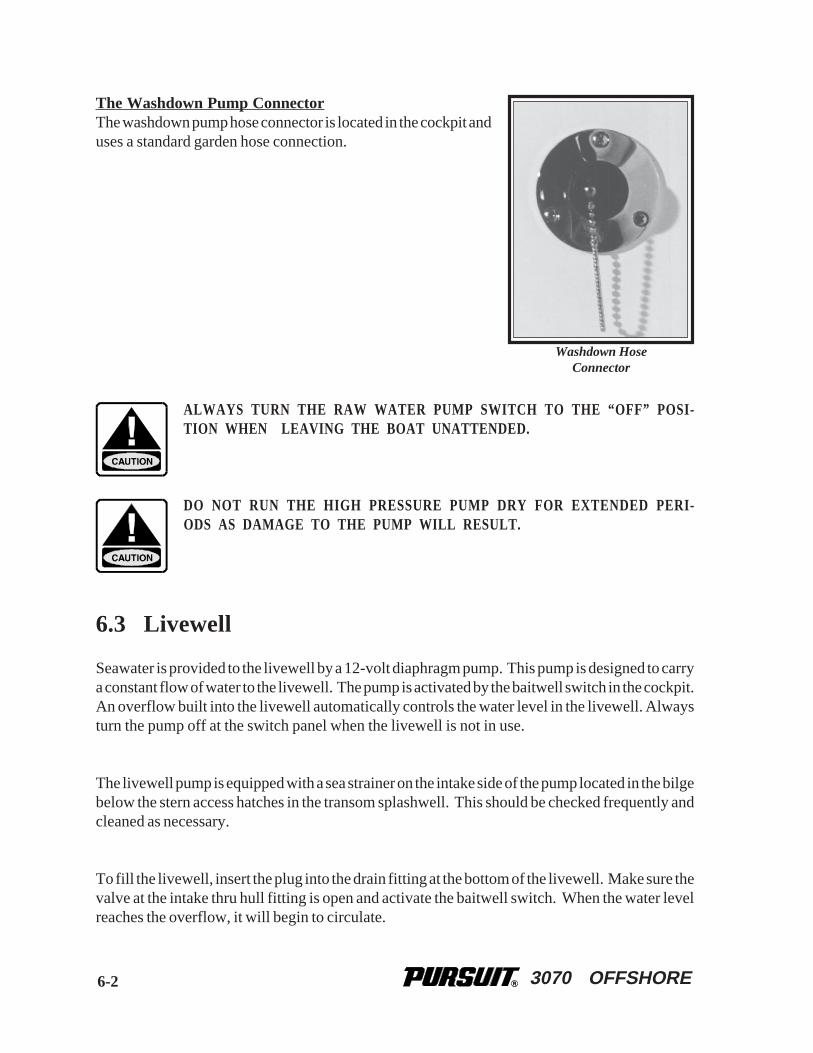
3070 OFFSHORE
The Washdown Pump ConnectorThe washdown pump hose connector is located in the cockpit anduses a standard garden hose connection.
ALWAYS TURN THE RAW WATER PUMP SWITCH TO THE “OFF” POSI-TION WHEN LEAVING THE BOAT UNATTENDED.
DO NOT RUN THE HIGH PRESSURE PUMP DRY FOR EXTENDED PERI-ODS AS DAMAGE TO THE PUMP WILL RESULT.
6.3 Livewell
Seawater is provided to the livewell by a 12-volt diaphragm pump. This pump is designed to carrya constant flow of water to the livewell. The pump is activated by the baitwell switch in the cockpit.An overflow built into the livewell automatically controls the water level in the livewell. Alwaysturn the pump off at the switch panel when the livewell is not in use.
The livewell pump is equipped with a sea strainer on the intake side of the pump located in the bilgebelow the stern access hatches in the transom splashwell. This should be checked frequently andcleaned as necessary.
To fill the livewell, insert the plug into the drain fitting at the bottom of the livewell. Make sure thevalve at the intake thru hull fitting is open and activate the baitwell switch. When the water levelreaches the overflow, it will begin to circulate.
6-2
Washdown HoseConnector

3070 OFFSHORE
To drain the livewell, turn off the livewell pump and pull out the plug in the drain fitting at thebottom of the livewell. When the livewell has completely drained, use the washdown hose to flushthe livewell and drain of debris.
The livewell supply thru hull valve should be closed whenever the livewell is not in use. This willprevent water from entering the livewell while the boat is cruising.
Note: Do not use the livewell as a dry storage area when it is not in use. Seawater couldaccidently be delivered to the livewell from the thru hull fitting and damageequipment stored there.
DO NOT RUN THE LIVEWELL PUMP DRY FOR EXTENDED PERIODS ASDAMAGE TO THE PUMP WILL RESULT.
ALWAYS TURN THE LIVEWELL PUMP SWITCH TO THE “OFF” POSITIONWHEN LEAVING THE BOAT UNATTENDED.
6.4 Air Conditioning Pump
The air conditioner is self-contained and seawater cooled. An AC centrifugal raw water pumpsupplies seawater that cools the condensing unit as it circulates through the system and is dischargedoverboard. The pump is located below the water line and is activated whenever 110-volt currentis available and the air conditioning system is operating.
Seawater is supplied to the pump from a thru hull fitting located in the hull near the pump. A seastrainer between the pump and thru hull fitting protects the system from contaminants that coulddamage the pump or the air conditioning system. Make sure the seawater pump receives adequateseawater by periodically cleaning the sea strainer basket.
Please refer to the air conditioner owner's manual for more information on the operation andmaintenance of the air conditioner.
6-3

3070 OFFSHORE6-4
6.5 Raw Water System Maintenance
The following items should be done routinely to help maintain your raw water system:
• Check hoses, particularly the seawater supply lines, for signs of deterioration.
• Remove and clean the seawater strainers for the livewell, air conditioner and washdown pump,as needed.
• Spray pumps and thru hull valves with a protective oil periodically.
• The fishboxes and livewells should be drained and cleaned after each use.
• Operate all thru hull valves at least once a month to keep them operating properly.
SHOULD A HOSE RUPTURE, TURN THE PUMP OFF IMMEDIATELY. AL-WAYS CLOSE THE THRU HULL VALVE WHEN PERFORMING MAINTE-NANCE ON A SEAWATER PUMP.
THE BATTERIES MUST BE PROPERLY CHARGED. OPERATING ANYPUMPS FROM A BATTERY WITH A LOW CHARGE MAY LEAD TO APUMP FAILURE.
THE RAW WATER SYSTEM MUST BE PROPERLY WINTERIZED PRIOR TOWINTER LAY-UP. SEE THE SECTION ON WINTERIZING
NOTICE
NOTICE
3070 OFFSHORE 7-1
Chapter 7:
DRAINAGE SYSTEMS
7.1 General
All water is drained by gravity to overboard thru hull fittings located in the hull sides above thewaterline. The cabin and some cockpit component drain thru hull fittings are equipped with PVCball valves that are always open under normal operating conditions. In the event of an emergency,the valves can be closed to prevent sea water from entering the boat through the drainage system.It is important to check and operate the drain valves at least annually to make sure they are in goodcondition and operating properly. You also should check the drain system frequently to ensure itis free flowing and that the hoses on the thru hull fittings are secure and not leaking.
Please review the drainage schematic to become familiar with the location of the thru hull drainvalves.
SITUATIONS REQUIRING ONE OR MORE DRAIN VALVES TO BE CLOSEDCAN BE POTENTIALLY DANGEROUS TO THE BOAT AND YOUR CREW.IF THIS OCCURS, DISTRIBUTE PERSONAL FLOTATION DEVICES TO THECREW AND TAKE ALL NECESSARY SAFETY PRECAUTIONS, INCLUDINGNOTIFYING THE COAST GUARD, UNTIL THE PROBLEM IS FOUND ANDCORRECTED.
7.2 Cockpit Drains
Your Pursuit has two scupper drains located in the rear of the cockpit. Water is channeled awayfrom all hatches by a gutter or drain rail system. The water then drains overboard through thescupper drain system.
7.3 Hard-Top Drains
There is a hole drilled in one of the leg bases to prevent water from being trapped within the legand provide a wire chase for accessories. A small hole is drilled in the tubing at the base of the otherlegs, which are not drilled for a wire chase, that allows water to drain.

3070 OFFSHORE7-2
ALWAYS MAKE SURE THE LEG DRAIN HOLES ARE CLEAR WHEN THEBOAT IS LAID UP FOR THE WINTER. WATER TRAPPED INSIDE THELEGS COULD FREEZE AND CAUSE THE LEGS TO SPLIT.
7.4 Bilge Drainage
The bilge pumps are activated both manually, by a switch in the helm station, and automatically,by a float switch. The automatic float switches remain activated when the battery switches are inthe “OFF” position and the batteries are connected. All bilge pumps pump water out of thru hullslocated above the waterline in the hull. The rear bilge pump and automatic switch are located nearthe transom, below the engine splashwell, and the forward pump and automatic switch are locatedin the bilge below the aft berth in the cabin.
Note: See Electrical Systems for additional information on bilge pump operation.
When the boat is out of the water the bilge can be drained by a thru hull drain located in the transomnear the bottom of the hull. The plug should be removed whenever the boat is hauled out of thewater and installed just prior to launching. It is important to check the drain plug regularly to makesure it is tight.
A LOOSE DRAIN PLUG WILL ALLOW SEA WATER TO ENTER THE BILGEAND COULD CAUSE THE BOAT TO SINK. IT IS VERY IMPORTANT TOCHECK THE DRAIN PLUG FREQUENTLY TO ENSURE IT IS PROPERLYTIGHTENED.
Important: Any oil spilled in the bilge must be thoroughly removed and properly disposedof before operating the bilge pump. The discharge of oil from the bilge is illegaland subject to a fine.
THE FEDERAL WATER POLLUTION CONTROL ACT PROHIBITS THE DIS-CHARGE OF OIL OR OILY WASTE INTO OR UPON THE NAVIGABLE WA-TERS OF THE UNITED STATES OR THE WATERS OF THE CONTIGUOUSZONE IF SUCH DISCHARGE CAUSES A FILM OR SHEEN UPON, OR A DIS-COLORATION OF THE SURFACE OF THE WATER, OR CAUSES A SLUDGEOR EMULSION BENEATH THE SURFACE OF THE WATER. VIOLATORSARE SUBJECT TO A PENALTY OF $10,000.
CERTAIN BULKHEAD AREAS ARE SEALED IN ACCORDANCE WITH U.S.COAST GUARD REGULATIONS THAT WERE IN EFFECT AT THE DATE OFMANUFACTURE OF THE BOAT. ANY MODIFICATIONS TO THESE BULK-HEADS SHOULD BE IN ACCORDANCE WITH THE U.S. COAST GUARDREGULATIONS.
3070 OFFSHORE
7.5 Fishbox, Cooler and Storage Compartment Drains
The cooler, located under the passenger seat in front of the console, is drained by the shower drainsump pump system. Water drains by gravity to the sump system, located in the bilge, where it ispumped overboard.
The rod locker and storage compartment drain by gravity to overboard thru hulls located in the hullsides just above the waterline.
The fishbox below the cockpit floor is drained overboard by a macerator pump out system. Themacerator is activated by a momentary switch located in a switch panel near the transom accessdoor. The fishboxes should be flushed out and cleaned after each use.
Note: The macerator discharge pump can only be run dry for a few seconds. Allowing themacerator pump to run after the fishbox is empty will cause damage to the pump.
7.6 Water System Drains
All exterior sinks and livewells, provided with fresh or raw water, drain by gravity to overboardthru hulls located in the hull sides just above the waterline. The overflows in the livewell drain intothe overboard drains.
7.7 Cabin Drains
The galley and head sink drain by gravity to overboard thru hulls located in the hull sides just abovethe waterline. The shower, air conditioner and console cooler are drained by a sump pump system.The sump system is located in the bilge and accessed through a hatch below the aft berth in the cabin.An automatic float switch in the sump controls the pump. The pump is protected by the showersump pump circuit breaker in the cabin DC panel. The sump has a removable hatch to allow thesystem to be inspected and serviced. It is essential that the sump system be inspected periodicallyand any accumulated debris removed.
The drain thru hull fittings for the sump pump and the sink drains are equipped with PVC ball valvesthat are always open under normal operating conditions. In the event of an emergency, the valvescan be closed to prevent sea water from entering the boat through the shower sump or drain system.The drain valve for the sump pump is located in the bilge below the port side of the aft berth. Thevalves for the head and galley sinks are located at the thru hull fitting for each drain. It is importantto check and operate the valves at least annually to make sure they are in good condition andoperating properly. Please review the drainage schematic to become familiar with the location ofthe sump pump and gravity drain thru hull valves.
7-3
3070 OFFSHORE
7.8 Rope Locker Drains
The rope locker drains overboard through a special drain fitting located in the hull side at the bottomof the rope locker. It is important to inspect the drain frequently to remove any accumulated debris.
7.9 Drainage System Maintenance
It is essential that the following items be done periodically to maintain proper drainage of your boat:
• Clean the cockpit drain rails with a hose to remove debris that can block water drainage.
• Clean the hardtop leg drain holes. This is especially important just before winter lay-up.
• Clean the bilge pump strainers of debris and check the bilge for foreign material that can causethe automatic switch to malfunction.
• Frequently test the automatic bilge pump switch for proper operation. This is accomplished byinserting a stiff wire or small rod through one of the slots in the float chamber of the pump andlifting the float switch until the pump is activated. You can also use a garden hose to flood thebilge until the water level is high enough to activate the pump.
• Flush all gravity drains with freshwater to keep them clean and free flowing.
• Clean and inspect the shower and drain sump system. Remove accumulated debris and flushwith freshwater. Frequently test the automatic pump switch for proper operation.
• Clean and flush the fishbox and cooler/storage boxes with soap or a bilge cleaner andfreshwater after each use to keep them clean and fresh.
• Operate the thru hull valves once a month and service as required.
Note: All drains and pumps must be properly winterized before winter lay-up.
NEVER USE HARSH CHEMICAL DRAIN CLEANERS IN MARINE DRAINSYSTEMS. PERMANENT DAMAGE TO THE HOSES AND FITTINGS MAYRESULT.
7-4
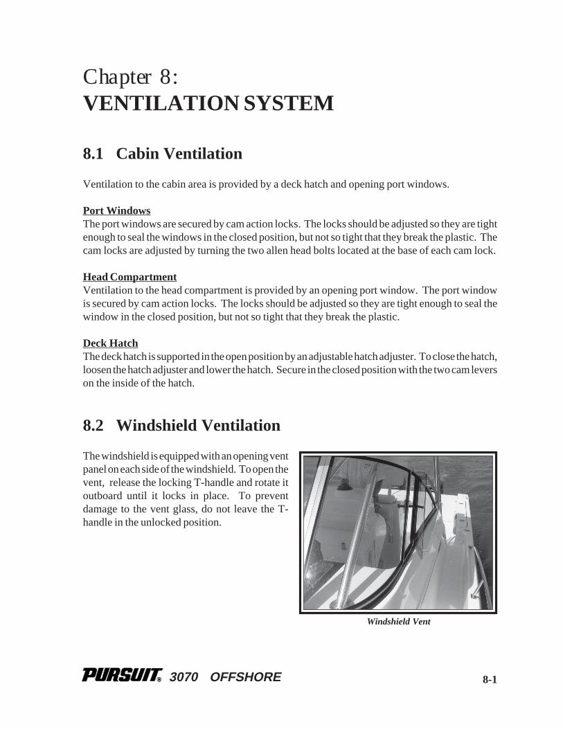
3070 OFFSHORE
Chapter 8:
VENTILATION SYSTEM
8.1 Cabin Ventilation
Ventilation to the cabin area is provided by a deck hatch and opening port windows.
Port WindowsThe port windows are secured by cam action locks. The locks should be adjusted so they are tightenough to seal the windows in the closed position, but not so tight that they break the plastic. Thecam locks are adjusted by turning the two allen head bolts located at the base of each cam lock.
Head CompartmentVentilation to the head compartment is provided by an opening port window. The port windowis secured by cam action locks. The locks should be adjusted so they are tight enough to seal thewindow in the closed position, but not so tight that they break the plastic.
Deck HatchThe deck hatch is supported in the open position by an adjustable hatch adjuster. To close the hatch,loosen the hatch adjuster and lower the hatch. Secure in the closed position with the two cam leverson the inside of the hatch.
8.2 Windshield Ventilation
The windshield is equipped with an opening ventpanel on each side of the windshield. To open thevent, release the locking T-handle and rotate itoutboard until it locks in place. To preventdamage to the vent glass, do not leave the T-handle in the unlocked position.
8-1
Windshield Vent

3070 OFFSHORE
8.3 Carbon Monoxide and Proper Ventilation
The Safety Chapter in this manual contains important information on carbon monoxide and thecarbon monoxide detector. Read the section entitled "Carbon Monoxide" in the Safety Chapterof this Owner's Manual.
8.4 Bilge Compartment Ventilation
All 3070 Offshore models are equipped with ventilation for the bilge compartment. A flow of airinto the bilge compartment is provided by four vents located on either side of the cockpit, under thegunnel boards. This provides adequate air movement in the bilge and generator compartments.
8.5 Maintenance
• Periodically lubricate all hinges and latch assemblies with a light oil.
• Periodically clean and coat gasket materials with silicone to help keep them pliable.
• The opening cabin deck hatches, port windows, venturi windshield and the curved section ineach front corner of the standard windshield are made of acrylic plastic glass. Acrylic glassscratches easily. Never use a dry cloth or glass cleaning solutions on acrylic glass . Use a softcloth and mild soap and water for routine cleaning. Solvents and products containing ammoniacan permanently damage acrylic glass. Please refer to the Routine Maintenance chapter formore information on the proper maintenance for acrylic plastic glass.
• Periodically return the carbon monoxide alarm to the manufacturer for testing and recalibration.Please refer to the carbon monoxide alarm manual or contact the manufacturer for moreinformation on maintaining and calibrating the alarm.
8-2
3070 OFFSHORE
Chapter 9:
EXTERIOR EQUIPMENT
9.1 Deck
Rails and Deck HardwareThe rail system and hardware fittings have been selected and installed to perform specific functions.Fenders or mooring lines should be secured to the cleats and not to rails or stanchions. Mooringlines should be secured to the cleats. Be sure a clear lead exists when running dock lines or anchorlines. A line inadvertently run around a stanchion or over the rail could cause damage.
Important: All fittings must be periodically inspected for loose fit or wear and damage.Any problems should be corrected immediately.
PURSUIT BOATS ARE NOT EQUIPPED WITH HARDWARE DESIGNED FORTOWING PURPOSES. THE MOORING CLEATS ARE NOT TO BE USED FORTOWING ANOTHER VESSEL OR HAVING THIS BOAT TOWED.
Bow Pulpit and RollerThe bow pulpit is built into the hull and is equipped with a roller assembly that allows the anchorto be operated and stored at the pulpit. The pulpit roller is designed for a Delta® plow or a Danforth®
style anchor. The anchor line is stored in the rope locker and routed out the rope locker hatch,through the roller and connected to the anchor chain. A cleat or chain binder is provided on thedeck near the pulpit to secure the anchor. Always make sure the anchor is properly secured whenit is in the stored position on the pulpit.
Anchor/Rope LockerThe anchor locker is in the bow of the boat and accessed through a hatch in the deck. The anchorline is always stored in the locker. The anchor locker has a built-in bracket for a “Danforth®” styleanchor. If the anchor is stored in the anchor locker, it must be properly secured to prevent it frombouncing in the locker and causing damage to the hull or anchor locker.
The anchor locker is drained by a thru hull fitting in the hull side near the bottom of the locker. Itis very important to check the drain frequently to make sure they are clean and free flowing.
9-1
3070 OFFSHORE
THE ANCHOR MUST BE POSITIONED SO IT DOES NOT REST AGAINSTTHE HULL SIDES AND BE PROPERLY SECURED AT ALL TIMES WHENIT IS STORED IN THE ANCHOR LOCKER. A LOOSE ANCHOR IN THE AN-CHOR LOCKER WILL BOUNCE AND CAN DAMAGE THE BOAT. DAM-AGE RESULTING FROM THE ANCHOR BOUNCING IN THE ANCHORLOCKER IS NOT COVERED BY THE PURSUIT WARRANTY.
Windlass (Optional)The optional windlass is mounted to the deck near the rear of the pulpit above the rope locker. Theanchor is stored on the pulpit and is raised and lowered by the windlass. The anchor line is storedin the rope locker and routed out through the windlass to the anchor chain.
The anchor is lowered by releasing the anchor from the cleat or chain binder on the pulpit andoperating a “down” control at the helm. After the anchor is set, the windlass must not be left to takethe entire force from the anchor line. Boats lying to their anchor in a high swell or heavy weatherconditions will snub on the line. This can cause slippage or apply excessive loads to the windlass.The line should be made fast to a bow cleat to relieve the load on the windlass.
The anchor is hauled in by releasing the line from the bow cleat and operating the “up” control atthe helm. Once the anchor is retrieved, independently secure the anchor to the chain binder or acleat to prevent it from being accidentally released. This is especially important while the boat isunder way.
The windlass manufacturer provides an owner’s manual with its product. It is extremely importantthat you read the manual and become familiar with the proper care and operation of the windlass.
A WINDLASS MUST BE USED WITH CARE. IT IS EXTREMELY IMPOR-TANT THAT YOU READ THE OWNER’S MANUAL AND BECOME FAMIL-IAR WITH THE SAFETY INSTRUCTIONS AND PROPER OPERATION OF THEWINDLASS BEFORE USING IT WITH YOUR BOAT. ALWAYS ENSURE THATLIMBS, FINGERS, HAIR AND CLOTHING ARE KEPT CLEAR OF THE WIND-LASS AND ANCHOR LINE DURING OPERATION.
DO NOT USE A WINDLASS AS A SOLE MEANS OF SECURING AN AN-CHOR IN THE BOW PULPIT. ALWAYS SECURE THE ANCHOR LINE TOA CLEAT OR CHAIN BINDER BEFORE OPERATING YOUR BOAT.
9-2

3070 OFFSHORE 9-3
WindshieldThe Pursuit 3070 Offshore is equipped with an optional vented heavy duty aluminum windshieldwith tinted glass and built in hand rails. The windshield is equipped with an opening vent panelon each side of the windshield. To open the vent, release the locking T-handle and rotate it outboarduntil it locks in place. To prevent damage to the vent glass, do not leave the T-handle in the unlockedposition. The front and side wing panels are tempered safety glass. The curved glass panels on theport and starboard side of the windshield are made of tinted acrylic plastic glass.
Acrylic glass scratches easily. Never use a dry cloth or glass cleaning solutions on acrylic. Usea soft cloth and mild soap and water for routine cleaning. Solvents and products containingammonia can permanently damage acrylic. Please refer to the Routine Maintenance chapter formore information on the proper care and maintenance of acrylic plastic glass.
9.2 Hull
Swim PlatformYour Pursuit is equipped with an integral swim platform and engine mounting system located inthe stern of the boat. There are three inspection deck plates in the transom engine well to provideaccess to the stern bilge and engine mounting bolts. Always make sure these plates are securebefore operating your boat.
Boarding LadderThe boarding ladder is mounted to the rear of the stern bait andtackle rigging station when it is in the stored position. To usethe ladder, remove it from the storage clips and slide the studsinto the special bracket on the port side of the transom. Theladder floats and must be secured in the boarding position byturning the cam lock on the ladder so it catches the bottom ofthe transom ladder bracket. The ladder must be removed fromthe transom bracket and properly secured to the storage clipsbefore starting the engine(s).
MOVING PROPELLERS ARE DANGEROUS. THEY CAN CAUSE DEATH,LOSS OF LIMBS, OR OTHER SEVERE INJURY. DO NOT USE THE SWIMPLATFORM OR SWIM LADDER WHILE THE ENGINE(S) ARE RUNNING.STOP THE ENGINE(S) IF DIVERS OR SWIMMERS ARE ATTEMPTING TOBOARD. ALWAYS REMOVE AND PROPERLY STORE THE LADDER BEFORESTARTING THE ENGINE(S).
Trim TabsThe trim tabs are recessed into the hull below the swim platform. The trim tabs are an importantpart of the control systems. Please refer to the Helm Control Systems chapter for detailedinformation on the trim tabs.
Boarding Ladder

3070 OFFSHORE
9.3 Cockpit
IN CERTAIN CONDITIONS, OPEN EXTERIOR DOORS AND HATCHESTHAT ARE NOT SECURED PROPERLY CAN SLAM CLOSED UNEXPECT-EDLY AND CAUSE INJURY TO PASSENGERS OR DAMAGE TO THE BOAT.MOST DOORS AND HATCHES ARE EQUIPPED WITH SPECIAL FASTEN-ERS, HATCH LIFTERS, OR SNAPS AND/OR STRAPS, TO SECURE THEMIN THE OPEN POSITION. ALWAYS MAKE SURE THAT THESE HATCHESAND DOORS ARE PROPERLY SECURED WHENEVER THEY ARE IN THEOPEN POSITION.
Rod StorageA large storage or rod compartment islocated below the leaning post and tacklestation. The rod storage hatch lifterswitch in the cockpit activates an elec-tric ram that raises the rear of the bridgedeck and the leaning post providingaccess to the rod storage area. A limitswitch on the leaning post seat adjusterprevents the rod storage hatch fromopening unless the seat is in the full aftposition. This prevents the seat andhelm equipment from being damagedwhen the leaning post and bridge deckis lifted to access the rod storage. If thebridge deck is closed and the hatch liftershould malfunction, it can be accessed by removing the tackle locker in the leaning post tacklestation.
The compartment is equipped with overboard drainage and rod racks for secure rod storage.
Leaning Post and Tackle StationThe leaning post is equipped with an adjustable seat. An electric ram activated by a switch at thehelm moves the seat forward or backward. The seat is in the leaning post position when it is in theaft position and can be used as a seat when it is adjusted forward. Always make sure the seat is inthe full aft position before opening the helm or the rod locker.
There are four tackle drawers and two storage compartments built into the rear of the leaning post.The tackle station doors can be locked to secure the drawers when the boat is unattended.
9-4
Rod Locker

3070 OFFSHORE
Stern Bait and Tackle Rigging StationThe stern bait and tackle rigging station isequipped with a transom door, sink, livewell,cutting board and rigged bait storage unit. Thesink is plumbed to the freshwater system anddrains overboard. The bait storage unit isinsulated and drains overboard. The livewell issupplied by a raw water circulating pump anddrains overboard. Refer to the Raw WaterSystem chapter for additional information onthe livewell.
The three drawer bait storage unit is equipped with special drawers that can be cooled with ice.
There is a hatch on the starboard side of the rigging station for the TABS system and the batteryswitches. The bait storage unit is removable to allow access to the stern bilge and the equipmentmounted in that area. To remove the bait storage unit, remove the screws in the frame and pull theunit straight out and into the cockpit. Always reseal the frame and screws with marine silicone caulkwhen the bait storage unit is reinstalled.
Below Deck Stern FishboxA fishbox is located in the stern below the cockpit sole. The fishbox is drained by a macerator pumplocated in the bilge and activated by a momentary switch in the rear of the cockpit near the sternbait and tackle rigging station. The fishbox should be pumped out and cleaned after each use. Referto the Drainage Systems chapter for more information on the fishbox drainage.
Transom DoorA transom door is incorporated into the rigging station. Thetransom door should only be operated when the boat is not inmotion. The door must be latched in either the full “OPEN” orfull “CLOSED” position. Never leave the transom door un-latched.
Note: Periodically inspect the transom door fittings forwear, damage, or loose fit. Any problems should beinspected and corrected immediately.
9-5
Stern Bait and Tackle Rigging Station
Transom Door

3070 OFFSHORE
THE TRANSOM DOOR SHOULD BE CLOSED AND PROPERLY LATCHEDWHENEVER THE ENGINE(S) ARE RUNNING. NEVER OPEN THE TRAN-SOM DOOR WHILE UNDERWAY OR IN ROUGH SEA CONDITIONS. IN CER-TAIN SITUATIONS, AN OPEN TRANSOM DOOR COULD ALLOW A SUB-STANTIAL AMOUNT OF WATER TO ENTER THE COCKPIT CREATING APOTENTIALLY DANGEROUS CONDITION.
OPERATING THE BOAT UNDER POWER WITH THE TRANSOM DOOROPEN MAY ALLOW PERSONS TO FALL OVERBOARD AND INTO BOATPROPELLERS OR TO BE LOST IN OPEN WATER. ALWAYS CHECK TOMAKE SURE THE TRANSOM DOOR IS PROPERLY CLOSED AND LATCHEDBEFORE STARTING THE ENGINES AND NEVER OPERATE THE BOAT UN-DER POWER WITH THE TRANSOM DOOR OPEN.
Helm and Electronics LockerThe helm and engine controls are located on the rear of the center console. Molded-in electronicsstorage is located forward of the engine controls. Four cup holders and a stern facing jump seat arelocated to the starboard side of the helm.
The top section of the console is hinged and opens to provide access to service the helm equipmentor install electronics. The console cushion backrests also can be removed to expose access holesthat make installing or servicing electronics easier. To open the helm portion of the console, releasethe clamps on the front of the console. Then activate the electric helm tilt ram with helm tilt switchlocated near the clamps at the front of the console. The top of the console will be tilted aft to exposethe underside of the helm.
If the electric helm lifter fails, the helm can be opened manually by removing the quick release pinat the top or bottom of the helm tilt ram. To access the pin with the helm closed, open the accesshatch below the helm accessory switches and pull the ring on the pin while someone holds the helmin the closed position or with the helm latches in place. Be careful, the helm is heavy and will opensuddenly when the pin is released.
The tilt ram is an important part of the helm latching system. Never operate the boat unless the tiltram is completely assembled and operating properly. You also should make sure the clamps areproperly secured when the helm is closed.
Note: The adjustable seat must be adjusted to the full aft position and the rod locker bridgedeck hatch must be completely closed before opening the helm. A safety switch in theseat prevents the helm tilt system from operating unless the seat is adjusted to the fullaft position.
9-6

3070 OFFSHORE
ALWAYS MAKE SURE THE HELM STATION CLAMPS AND TILT RAM AREPROPERLY SECURED BEFORE OPERATING OR TRAILERING YOUR BOAT.IF THE HELM STATION IS NOT PROPERLY SECURED, IT COULD OPENUNEXPECTEDLY AND DAMAGE THE BOAT OR CAUSE LOSS OF CON-TROL.
UNDER NO CIRCUMSTANCES SHOULD THE HELM BE OPENED WHEN THEENGINE(S) ARE RUNNING. IN SOME SITUATIONS IT IS POSSIBLE TO AC-CIDENTALLY ENGAGE THE ENGINE SHIFT AND THROTTLE CONTROLINTO GEAR AS THE HELM IS OPENING. THIS COULD RESULT IN LOSSOF CONTROL, DAMAGE TO THE BOAT, AND INJURY TO PASSENGERS.
THE HELM IS HEAVY AND WILL OPEN SUDDENLY IF THE HELM CLAMPSARE RELEASED AND THE TILT RAM PIN IS REMOVED FROM THE RAM.THIS COULD CAUSE INJURY TO PEOPLE NEAR THE HELM OR DAMAGETHE BOAT. IT IS EXTREMELY IMPORTANT THAT THE HELM CLAMPSARE SECURED BEFORE REMOVING THE PIN FROM THE TILT RAM.ONCE THE RAM PIN IS REMOVED, THE HELM CLAMPS CAN BE RE-LEASED AND THE CONSOLE CAN BE LOWERED AGAINST THE RETAIN-ING STRAPS.
Console CoolerA molded insulated cooler is installed under the front seat of the console. The cooler drainsoverboard thru the shower sump drain system. The cooler should be cleaned thoroughly after eachuse.
Console StorageA storage compartment is under the seat on starboard of the console cooler. The engine batteriesand oil tanks are mounted in this compartment.
Cabin doorThe sliding cabin door is made of acrylic plastic glass and slides on a top and bottom track. Alockable latch secures the door in the closed position. A special vinyl-covered latch secures the doorin the open position.
It is very important that the cabin door is secured properly in the open or closed position. The cabindoor is heavy and if the door is not properly latched, it could slide when the boat rocks and pinchsomeone’s fingers between the door and the bulkhead or damage the door.
When closing the door, make sure you push the door against the door jam with enough pressureto allow the latch to secure the door. When the door is open, it must be properly secured with thelatch near the bottom door track and to the port side of the companionway. To latch the door inthe open position, open the door until it hits the rubber bumper on the bulkhead. Then push the dooragainst the bumper, slightly compressing the bumper and allowing the vinyl covered latch to securethe door in the open position.
9-7

3070 OFFSHORE
The door is made of acrylic plastic glass. Acrylic glass scratches easily and can chip. Always makesure the bulkhead bumper and the vinyl-covered latch are in good condition. They should bechanged whenever they show signs of deterioration from the exposure to elements. Please referto the Routine Maintenance chapter for information on the proper care and maintenance of acrylicplastic glass.
NEVER LEAVE THE CABIN DOOR UNLATCHED. THE CABIN DOOR ISHEAVY AND SLIDES EASILY. IF THE DOOR IS LEFT UNLATCHED, ITCOULD SLIDE UNEXPECTEDLY AS THE BOAT ROCKS, DAMAGING THEDOOR OR CAUSING AN INJURY TO A PASSENGER. ALWAYS MAKE SURETHE DOOR IS PROPERLY LATCHED IN THE OPEN OR CLOSED POSITION.
Hard TopThe optional hard top consists of a laminated fiberglass top mounted to a welded aluminum framethat is bolted to the deck. It is designed to accommodate radio antennas, radar antennas andnavigation lights. It could also be equipped with optional Top Gun outriggers and/or rod holders.
The hard top is not designed to support the additional weight of items like an instrument locker ora life raft. Radar and electronics antennas must be mounted to the top between the front and rearlegs. Do not mount any antennas or equipment to the brow area forward of the front legs. Thehard top frame is not designed to support the weight of accessories in this area and could bedamaged. The starboard rear leg is the wire chase for lights and antennas mounted to the top.
The warranty for the hard top will be void if the top is modified in any way or heavy accessorieslike life rafts, or electronics lockers are mounted to the top. Additionally, if items like radar antennasspotlights and other accessories are mounted in the wrong location, the warranty could be void. Ifyou intend to add equipment or make modifications to the hard top, you should contact PursuitCustomer Relations to make sure the equipment you would like to add or the intended modificationwill not void the warranty on the top.
Because the aluminum frames vary slightly, the side curtains, front clear connector and drop curtainare custom made to each boat at the factory. To install the curtains, slide the front clear connectorinto the slide track at the front of the top and snap it to the top of the windshield frame (fullwindshield) or to the windshield landing on the deck (venturi windshield) beginning with the centersnaps. The clear connector will have to be stretched just enough to pull out the wrinkles to reachthe snaps on the windshield or the deck.
Once the clear connector is completely installed, the side curtains can be put on. Slide the sidecurtains into the slide tracks on the sides of the top and to the zippers on the front connector. Snapthe curtains to the windshield and the deck beginning with the forward snaps on the windshield.The side curtains will have to be stretched slightly to pull out the wrinkles and reach the snaps.
If you have an optional drop curtain, slide it into the slide track on the back of the hard top and attachit to the rear of the side curtains. Snap the drop curtain to the deck and cockpit.
9-8

3070 OFFSHORE 9-9
Note: Cold weather can make the clear vinyl material on the curtains stiff and difficult tostretch to the snaps. This can particularly difficult with new canvas that has beenstored off the boat. Laying the curtains in the sun for 30 minutes during the heat ofthe day will make installing them much easier in cold weather.

3070 OFFSHORE
THIS PAGE WAS LEFT BLANKINTENTIONALLY
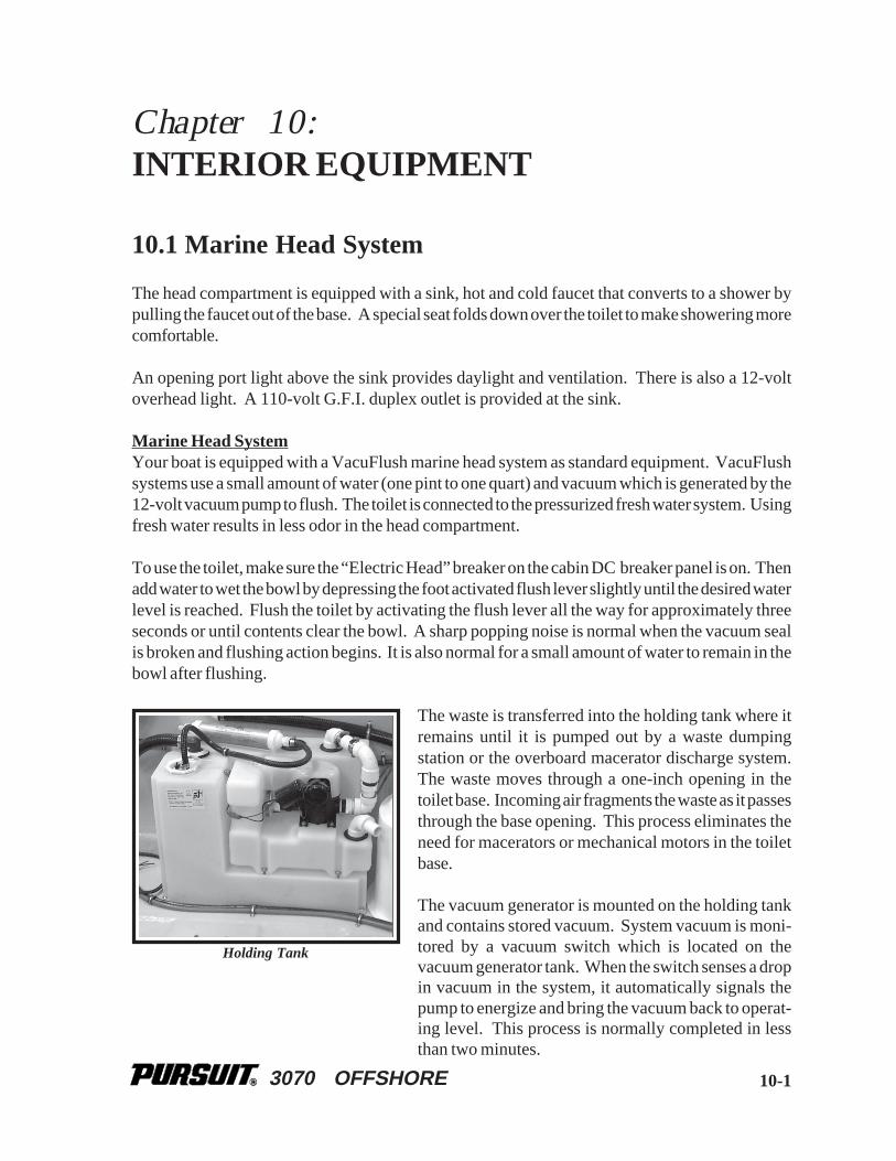
3070 OFFSHORE
Chapter 10:INTERIOR EQUIPMENT
10.1 Marine Head System
The head compartment is equipped with a sink, hot and cold faucet that converts to a shower bypulling the faucet out of the base. A special seat folds down over the toilet to make showering morecomfortable.
An opening port light above the sink provides daylight and ventilation. There is also a 12-voltoverhead light. A 110-volt G.F.I. duplex outlet is provided at the sink.
Marine Head SystemYour boat is equipped with a VacuFlush marine head system as standard equipment. VacuFlushsystems use a small amount of water (one pint to one quart) and vacuum which is generated by the12-volt vacuum pump to flush. The toilet is connected to the pressurized fresh water system. Usingfresh water results in less odor in the head compartment.
To use the toilet, make sure the “Electric Head” breaker on the cabin DC breaker panel is on. Thenadd water to wet the bowl by depressing the foot activated flush lever slightly until the desired waterlevel is reached. Flush the toilet by activating the flush lever all the way for approximately threeseconds or until contents clear the bowl. A sharp popping noise is normal when the vacuum sealis broken and flushing action begins. It is also normal for a small amount of water to remain in thebowl after flushing.
The waste is transferred into the holding tank where itremains until it is pumped out by a waste dumpingstation or the overboard macerator discharge system.The waste moves through a one-inch opening in thetoilet base. Incoming air fragments the waste as it passesthrough the base opening. This process eliminates theneed for macerators or mechanical motors in the toiletbase.
The vacuum generator is mounted on the holding tankand contains stored vacuum. System vacuum is moni-tored by a vacuum switch which is located on thevacuum generator tank. When the switch senses a dropin vacuum in the system, it automatically signals thepump to energize and bring the vacuum back to operat-ing level. This process is normally completed in lessthan two minutes.
10-1
Holding Tank

3070 OFFSHORE10-2
It is normal for the stored vacuum to leak down slightly between flushes, causing the vacuum pumpto run for a short period. The pump should not run more than once every three hours after the lastflush for recharging the system. Please refer to the toilet manufacturer owner’s manual for moreinformation on the operation of the marine head system.
Holding Tank and Macerator Discharge PumpThe holding tank is located in the compartment behind the head. When the tank is full, the tankmonitor will show full and the vacuum pump will not run. The tank must either be pumped out byan approved waste dumping station through the waste deck fitting or be pumped overboard withthe optional macerator discharge pump, when legal to do so. There is no Y-valve in this system.
To operate the macerator discharge pump, open the ball valve at the overboard discharge thru hullfitting below the aft berth. Then activate the momentary macerator switch located in the holdingtank monitor panel in the head compartment, until the tank is emptied. Release the switch and closethe discharge ball valve when pumping is complete.
Note: The macerator discharge pump can only be run dry for a couple of seconds. Allowingthe macerator pump to run after the holding tank is empty will cause damage to thepump.
IN MANY AREAS IT IS ILLEGAL TO FLUSH HEAD WASTE DIRECTLYOVERBOARD. VIOLATION OF THESE POLLUTION LAWS CAN RESULTIN FINES OR IMPRISONMENT. ALWAYS KNOW THE LAW FOR THE AR-EAS IN WHICH YOU BOAT. NEVER DUMP HEAD OR HOLDING TANKWASTE OVERBOARD ILLEGALLY.
MaintenanceThe head should be cleaned and inspected for leaks regularly.
The holding tank should be pumped out and flushed as needed. Periodically add chemical to thehead to help control odor and to chemically break down the waste. See the manufacturer owner’smanual for additional operating and maintenance information.
THE HEAD AND MACERATOR DISCHARGE SYSTEM MUST BE PROPERLYWINTERIZED BEFORE WINTER LAY-UP. SEE THE SECTION ON WINTER-IZING
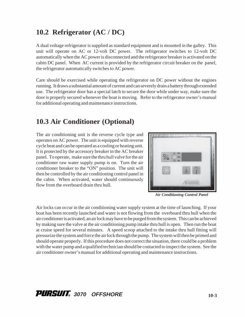
3070 OFFSHORE 10-3
10.2 Refrigerator (AC / DC)
A dual voltage refrigerator is supplied as standard equipment and is mounted in the galley. Thisunit will operate on AC or 12-volt DC power. The refrigerator switches to 12-volt DCautomatically when the AC power is disconnected and the refrigerator breaker is activated on thecabin DC panel. When AC current is provided by the refrigerator circuit breaker on the panel,the refrigerator automatically switches to AC power.
Care should be exercised while operating the refrigerator on DC power without the enginesrunning. It draws a substantial amount of current and can severely drain a battery through extendeduse. The refrigerator door has a special latch to secure the door while under way, make sure thedoor is properly secured whenever the boat is moving. Refer to the refrigerator owner’s manualfor additional operating and maintenance instructions.
10.3 Air Conditioner (Optional)
The air conditioning unit is the reverse cycle type andoperates on AC power. The unit is equipped with reversecycle heat and can be operated as a cooling or heating unit.It is protected by the accessory breaker in the AC breakerpanel. To operate, make sure the thru hull valve for the airconditioner raw water supply pump is on. Turn the airconditioner breaker to the “ON” position. The unit willthen be controlled by the air conditioning control panel inthe cabin. When activated, water should continuouslyflow from the overboard drain thru hull.
Air locks can occur in the air conditioning water supply system at the time of launching. If yourboat has been recently launched and water is not flowing from the overboard thru hull when theair conditioner is activated, an air lock may have to be purged from the system. This can be achievedby making sure the valve at the air conditioning pump intake thru hull is open. Then run the boatat cruise speed for several minutes. A speed scoop attached to the intake thru hull fitting willpressurize the system and force the air lock through the pump. The system will then be primed andshould operate properly. If this procedure does not correct the situation, there could be a problemwith the water pump and a qualified technician should be contacted to inspect the system. See theair conditioner owner’s manual for additional operating and maintenance instructions.
Air Conditioning Control Panel

3070 OFFSHORE10-4
Note: Air conditioners use surface water as a cooling medium. The boat must be in thewater and the raw water supply system must be properly activated prior to use.Operation without proper cooling will cause the air conditioning circuit breaker totrip and could cause system damage. Always check for proper water flow out of theair conditioning pump discharge thru hull when the air conditioner is operating.
10.4 Galley and Sink
The galley is equipped with storage and a fresh water sink. Water is supplied to the sink by a 12-volt pump located in the stern bilge. When activated by the “Fresh Water System” breaker in the12-volt panel, the system will operate much like the water system in a home. An automatic pressuresensor keeps the system pressurized. The sink drains overboard through the cabin drain system.
See the Freshwater Systems chapter for more information on the freshwater system.
The companionway steps are hinged and can befolded to provide access to the aft berth and moreroom when in the galley or to access the aft berth.The steps are held in the folded position by abracket on the cabin bulkhead. Always make surethe steps are properly secured when they are in thefolded position.
Microwave OvenA microwave oven is provided as standard equipment on the 3070 Offshore. The microwaveoperates on AC power and is protected by the microwave breaker in the AC breaker panel.
Please refer to the microwave owner's manual for detailed information on the microwave oveninstalled in your boat.
Companionway steps

3070 OFFSHORE 10-5
10.5 Carbon Monoxide Detector
The Safety Chapter in this manual contains important information on carbon monoxide and thecarbon monoxide detector. Read the section entitled "Carbon Monoxide" in the Safety Chapterof this Owner's Manual.
10.6 Convertible V-Berth and Table
The V-berth is equipped with a table that will seat four people when the table is in the up position.There is storage below a hatch under each V-berth cushion. The table is mounted on an adjustablepedestal that allows the dinette to be converted to a double berth.
To convert the dinette to a double berth, lift the cam lock lever on the pedestal base. Then carefullypush the table down until it seats on the teak table supports on each side of the V-berth. Secure thetable in the down position by pushing the cam lock lever down on the pedestal base. Place theseparate berth cushions on the table top to complete the berth conversion. The table should belowered to the berth position whenever the boat is run offshore or in heavy sea conditions to preventdamage to the pedestal assembly.
Daylight and fresh air is provided to this area by two opening port windows and by an overheadopening hatch. Additional lighting is provided by 12-volt lights on the bulkheads. The airconditioning control unit, the AC and DC breaker panels, and the carbon monoxide detector arelocated on the galley bulkhead.

3070 OFFSHORE
THIS PAGE WAS LEFT BLANKINTENTIONALLY
3070 OFFSHORE
Chapter 11:
SAFETY EQUIPMENT
11.1 General
Your boat and outboard engines have been equipped with safety equipment designed to enhancethe safe operation of the boat and to meet U.S. Coast Guard safety standards. The Coast Guardor state, county, and municipal law enforcement agencies require certain additional accessorysafety equipment on each boat. This equipment varies according to length and type of boat and typeof propulsion. Most of the accessory equipment required by the Coast Guard is described in thischapter. Some local laws require additional equipment. It is important to obtain “FederalRequirements And Safety Tips for Recreational Boats,” published by the Coast Guard, and copiesof state and local laws, to make sure you have the required equipment for your boating area. Youshould also read the book entitled “Sportfish, Cruisers, Yachts - Owner's Manual,” included withthis manual.
Your Pursuit could be equipped with engine alarms and cabin monitoring equipment. Thesesystems are designed to increase your boating safety by alerting you to potentially serious problemsin the primary power systems, the engine compartment, and the cabin. Alarm systems are notintended to lessen or replace good maintenance and precruise procedures.
This chapter also describes safety related equipment that could be installed on your boat. Thisequipment will vary depending on the type of engines and other options installed by you or yourdealer.
11.2 Engine Alarms
Most outboards and generator engines are equipped with an audible alarm system mounted in thehelm area that monitors selected critical engine systems. The alarm will sound if one of thesesystems begins to fail. Refer to the engine owner’s manual for information on the alarms installedwith your engines.
If the alarms sounds:
• Immediately throttle the engines back to idle.
• Shift to neutral.
• Monitor the engine gauges to determine the cause of the problem.
11-1

3070 OFFSHORE
• If necessary, shut off the engines and investigate until the cause of the problem is found.
• If the boat is equipped with water sensors in the fuel filters, be sure to check them for excessivewater.
11.3 Neutral Safety Switch
Every control system has a neutral safety switch incorporated into it. This device prohibits theengines from being started while the shift lever is in any position other than the neutral position andshould be inspected and tested periodically to ensure the switch is working. If the engines will notstart, slight movement of the shift levers may be necessary to locate the neutral position anddisengage the safety cutout switch. Control or cable adjustments may be required to correct thiscondition should it persist. See your Pursuit dealer for necessary control and cable adjustments.Please refer to the Helm Control Systems chapter for more information on the neutral safety switch.
11.4 Engine Stop Switch
Your Pursuit is equipped with a engine stop switch and lanyard. Whenthe lanyard is pulled it will engage the switch and shut off the engines. Westrongly recommend that the lanyard be attached to the driver and the stopswitch whenever the engines are running. If the engines will not start, itcould be because the lanyard is not properly inserted into the engine stopswitch. Always make sure the lanyard is properly attached to the enginestop switch before attempting to start the engine.
Note: You should carry an extra stop switch lanyard and instruct at least one other crewmember on the operation of the stop switch and location of the extra lanyard.
11.5 Required Safety Equipment
Besides the equipment installed on your boat by Pursuit, certain other equipment is required by theU.S. Coast Guard to help ensure passenger safety. Items like a sea anchor, working anchor, extradock lines, flare pistol, life vests, a line permanently secured to your ring buoy, etc., could at sometime save your passengers’ lives, or save your boat from damage. Refer to the “FederalRequirements And Safety Tips For Recreational Boats” pamphlet for a more detailed descriptionof the required equipment. You can also contact the U.S. Coast Guard Boating Safety Hotline, 800-
11-2
Engine Stop Switch

3070 OFFSHORE
368-5647 or the “Boat U.S. Foundation Course Hotline,” 1-800-336-2628 and 800-245-2628 inVirginia, for information on boat safety courses and brochures listing the Federal equipmentrequirements. Also, check your local and state regulations.
The Coast Guard Auxiliary offers a “Courtesy Examination.” This inspection will help ensure thatyour boat is equipped with all of the necessary safety equipment.
The following is a list of the accessory equipment required on your boat by the U.S. Coast Guard:
Personal Flotation Devices (PFDs):PFDs must be Coast Guard approved, in good and serviceable condition, and of appropriate sizefor the intended user. Wearable PFDs must be readily accessible, meaning you must be able to putthem on in a reasonable amount of time in an emergency. Though not required, the Coast Guardemphasizes that PFDs should be worn at all times when the vessel is underway. Throwable devicesmust be immediately available for use. All Pursuit boats must be equipped with at least one TypeI, II or III PFD for each person on board, plus one throwable device (Type IV).
Visual Distress Signals:All Pursuit boats used on coastal waters, the Great Lakes, territorial seas, and those watersconnected directly to them, must be equipped with Coast Guard approved visual distress signals.These signals are either Pyrotechnic or Non-Pyrotechnic devices.
Pyrotechnic Visual Distress Signals:Pyrotechnic visual distress signals must be Coast Guard approved, in serviceable condition, andreadily accessible. They are marked with a date showing the service life, which must not haveexpired. A minimum of three are required. Some pyrotechnic signals meet both day and night userequirements. They should be stored in a cool, dry location. They include:
• Pyrotechnic red flares, hand held or aerial.
• Pyrotechnic orange smoke, hand-held or floating.
• Launchers for aerial red meteors or parachute flares.
PYROTECHNICS ARE UNIVERSALLY RECOGNIZED AS EXCELLENT DIS-TRESS SIGNALS. HOWEVER, THERE IS POTENTIAL FOR INJURY ANDPROPERTY DAMAGE IF NOT PROPERLY HANDLED. THESE DEVICESPRODUCE A VERY HOT FLAME AND THE RESIDUE CAN CAUSE BURNSAND IGNITE FLAMMABLE MATERIAL. PISTOL LAUNCHED AND HAND-HELD PARACHUTE FLARES AND METEORS HAVE MANY CHARACTERIS-TICS OF A FIREARM AND MUST BE HANDLED WITH CAUTION. IN SOMESTATES THEY ARE CONSIDERED A FIREARM AND PROHIBITED FROMUSE. ALWAYS BE EXTREMELY CAREFUL AND FOLLOW THEMANUFACTURER'S INSTRUCTIONS EXACTLY WHEN USING PYROTECH-NIC DISTRESS SIGNALS.
11-3
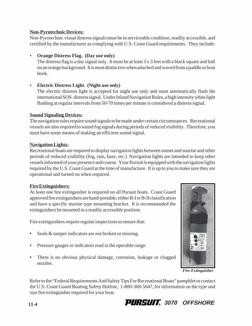
3070 OFFSHORE
Non-Pyrotechnic Devices:Non-Pyrotechnic visual distress signals must be in serviceable condition, readily accessible, andcertified by the manufacturer as complying with U.S. Coast Guard requirements. They include:
• Orange Distress Flag. (Day use only)The distress flag is a day signal only. It must be at least 3 x 3 feet with a black square and ballon an orange background. It is most distinctive when attached and waved from a paddle or boathook.
• Electric Distress Light. (Night use only)The electric distress light is accepted for night use only and must automatically flash theinternational SOS. distress signal. Under Inland Navigation Rules, a high intensity white lightflashing at regular intervals from 50-70 times per minute is considered a distress signal.
Sound Signaling Devices:The navigation rules require sound signals to be made under certain circumstances. Recreationalvessels are also required to sound fog signals during periods of reduced visibility. Therefore, youmust have some means of making an efficient sound signal.
Navigation Lights:Recreational boats are required to display navigation lights between sunset and sunrise and otherperiods of reduced visibility (fog, rain, haze, etc.) Navigation lights are intended to keep othervessels informed of your presence and course. Your Pursuit is equipped with the navigation lightsrequired by the U.S. Coast Guard at the time of manufacture. It is up to you to make sure they areoperational and turned on when required.
Fire Extinguishers:At least one fire extinguisher is required on all Pursuit boats. Coast Guardapproved fire extinguishers are hand-portable, either B-I or B-II classificationand have a specific marine type mounting bracket. It is recommended theextinguishers be mounted in a readily accessible position.
Fire extinguishers require regular inspections to ensure that:
• Seals & tamper indicators are not broken or missing.
• Pressure gauges or indicators read in the operable range.
• There is no obvious physical damage, corrosion, leakage or cloggednozzles.
Refer to the “Federal Requirements And Safety Tips For Recreational Boats” pamphlet or contactthe U.S. Coast Guard Boating Safety Hotline, 1-800-368-5647, for information on the type andsize fire extinguisher required for your boat.
Fire Extinguisher
11-4
3070 OFFSHORE
Please refer to the information provided by the fire extinguisher manufacturer for instructions onthe proper maintenance and use of your fire extinguisher.
INFORMATION FOR HALON OR AGENT FE-241 FIRE EXTINGUISHERS ISPROVIDED BY THE MANUFACTURER. IT IS ESSENTIAL THAT YOU READTHE INFORMATION CAREFULLY AND COMPLETELY UNDERSTAND THESYSTEM, IN THEORY AND OPERATION, BEFORE USING YOUR BOAT.
Bilge and Fuel FiresFuel compartment and bilge fires are very dangerous because of the presence of gasoline in thevarious components of the fuel system and the possibility for explosion. You must make thedecision to fight the fire or abandon the boat. If the fire cannot be extinguished quickly or it is toointense to fight, abandoning the boat may be your only option. If you find yourself in this situation,make sure all passengers have a life preserver on and go over the side and swim well upwind ofthe boat. This will keep you and your passengers well clear of any burning fuel that could bereleased and spread on the water as the boat burns or in the event of an explosion. When clear ofthe danger, check about and account for all those who were aboard with you. Give whateverassistance you can to anyone in need or in the water without a buoyant device. Keep everyonetogether in a group for morale and to aid rescue operations.
GASOLINE CAN EXPLODE. IN THE EVENT OF A FUEL COMPARTMENTOR BILGE FIRE, YOU MUST MAKE THE DIFFICULT DECISION TO FIGHTTHE FIRE OR ABANDON THE BOAT. YOU MUST CONSIDER YOURSAFETY, THE SAFETY OF YOUR PASSENGERS, THE INTENSITY OF THEFIRE AND THE POSSIBILITY OF AN EXPLOSION IN YOUR DECISION.
11.6 Carbon Monoxide
11-5
CARBON MONOXIDE IS A LETHAL, TOXIC GAS THAT IS COLORLESS ANDODORLESS. IT IS A DANGEROUS GAS THAT WILL CAUSE DEATH IN CER-TAIN LEVELS.
Carbon Monoxide Detector
A carbon monoxide (CO) detector is installed in the cabin on the rear bulkhead. If excess carbonmonoxide fumes are detected, the detector will sound an alarm indicating the presence of the toxicgas.
ACTUATION OF THE CARBON MONOXIDE DETECTOR INDICATES THEPRESENCE OF CARBON MONOXIDE (CO) WHICH CAN BE FATAL.EVACUATE THE CABIN IMMEDIATELY. DO A HEAD COUNT TO CHECKTHAT ALL PERSONS ARE ACCOUNTED FOR. DO NOT REENTER THECABIN UNTIL IT HAS BEEN AIRED OUT AND THE PROBLEM FOUND ANDCORRECTED.

3070 OFFSHORE
The carbon monoxide detector warns the occupants of dangerousaccumulation of carbon monoxide gas. It is automatically activatedwhenever the house battery switch is in the “on” position, energizingthe cabin DC breaker panel. Upon power up, the green powerindicator will flash for ten to fifteen minutes. The feature indicates theunit is in its warm-up stage. The green power indicator will stopflashing when the sensor has reached optimum operating temperature.The power indicator will then switch from flashing green to solidgreen to indicate that the carbon monoxide detector is activiated.
This device uses a micro controller to continuously measure andaccumulate CO levels. Should a very high level of carbon monoxideexist, the alarm will sound within a few minutes. However, if smallquantities of CO are present or high levels are short-lived, the detectorwill accumulate the information and determine when an alarm levelhas been reached.
Always make sure the battery switch is “on” and the power light on the carbon monoxidedetector is lit whenever the cabin is occupied.
While a CO detector enhances your protection from CO poisoning, it does not guarantee it will notoccur. Do not use the carbon monoxide detector as a replacement for ordinary precautions orperiodic inspections of equipment. Never rely on alarm systems to save your life, common senseis still prudent and necessary. Remember, the operator of the boat carries the ultimate responsiblityto make sure the boat is properly ventilated and the passengers are not exposed to dangerous levelsof carbon monoxide. You should always be alert to the symptoms and early warning signs ofcarbon monoxide.
Carbon Monoxide Detector
CO DETECTORS ARE VERY RELIABLE AND RARELY SOUND FALSEALARMS. IF THE ALARM SOUNDS, ALWAYS ASSUME THE HAZARD ISREAL AND MOVE PERSONS WHO HAVE BEEN EXPOSED TO CARBONMONOXIDE INTO FRESH AIR IMMEDIATELY. NEVER DISABLE THE CODETECTOR BECAUSE YOU THINK THE ALARM MAY BE FALSE.
Carbon Monoxide Poisoning
Carbon monoxide (CO), a by-product of combustion, is invisible, tasteless, odorless and isproduced by all engines and most heating and cooking appliances. It exists wherever fuels areburned to generate power or heat. The most common sources of CO on boats are gasoline enginesand auxiliary generators and propane or butane stoves. These produce large amounts of CO andshould never be operated while sleeping. High concentrations of CO can be fatal within minutes.Many cases of carbon monoxide poisoning indicate that while victims are aware they are not well,
11-6

3070 OFFSHORE
they become so disoriented they are unable to save themselves by either exiting the area or callingfor help. Also, young children, elderly persons and pets may be the first affected. Drug or alcoholuse increases the effect of CO exposure. Individuals with cardiac or respiratory conditions are verysusceptible to the dangers of carbon monoxide. CO poisoning is especially dangerous during sleepwhen victims are unaware of any side effects.
Low levels of carbon monoxide over an extended period of time can be just as lethal as high dosesover a short period. Therefore, low levels of carbon monoxide can cause the alarm to sound beforethe occupants of the boat notice any symptoms of carbon monoxide poisoning. CO detectors arevery reliable and rarely sound false alarms. If the alarm sounds, always assume the hazard is realand move persons who have been exposed to carbon monoxide into fresh air immediately. Neverdisable the CO detector because you think the alarm may be false. Always contact the detectormanufacturer, the Pursuit Customer Relations Department or your local fire department forassistance in finding and correcting the situation.
CO POISONING PRODUCES FLU-LIKE SYMPTOMS: WATERY AND ITCHYEYES, HEADACHES AND FATIGUE. YOU CAN’T SEE IT AND YOU CAN’TSMELL IT. IT’S AN INVISIBLE KILLER.
The following are symptoms which may signal exposure to CO: dizziness, flushed face, earsringing, headaches, tightness of chest or hyperventilation, drowsiness, fatigue or weakness,inattention or confusion, lack of normal coordination, nausea and unconsciousness. The victim’sskin also may turn red. A slight build-up of carbon monoxide in the human body over several hourscauses headache, nausea and other symptoms similar to food poisoning, motion sickness or the flu.Anyone with these symptoms should immediately be moved to an area of fresh air. Have the victimbreath deeply and seek immediate medical attention. To learn more about CO poisoning, contactyour local health authorities.
In certain situations, boats can have a problemdue to the “station wagon effect” where en-gine exhaust fumes are captured in the vesselby the vacuum or low pressure area, usuallythe cockpit, bridge deck and cabin, that can becreated by the forward speed of the boat.Boats that are underway should close all aftfacing portholes, hatches and doors. Theforward facing deck hatches should be openwhenever possible to help pressurize the liv-ing spaces of the boat. Sleeping, particularlyin aft cabins, should not be permitted whileunderway. Proper ventilation should be main-tained on the bridge deck by opening a for-ward window or windshield to drive fumes
11-7

3070 OFFSHORE
11.7 First Aid
It is the operator's responsibility to be familiar with the properfirst-aid procedures and be able to care for minor injuries orillnesses of your passengers. In an emergency, you could be farfrom professional medical assistance. We strongly recommendthat you be prepared by receiving training in basic first aid andCPR. This can be done through classes given by the Red Crossor your local hospital.
11-8
away from the occupants. The canvas drop or aft curtain must be removed and the side curtainsshould be opened or removed to increase air flow and maintain proper ventilation whenever theengines are running.
UNDER NO CIRCUMSTANCES SHOULD THE ENGINES BE OPERATINGWITH SIDE CURTAINS CLOSED AND THE AFT OR DROP CURTAIN IN-STALLED.
Extreme caution must be taken while at anchor or in a slip and an auxiliary power generator isoperating. Wind still nights can easily allow fumes to enter the boat. Inspect the exhaust systemsof propulsion and the auxiliary generators, if installed, frequently for possible leaks. Highconcentrations of CO in your boat may originate from an adjacent boat. Exhaust fumes from nearbyboats may enter your boat through open hatches or windows.
FAILURE TO PROPERLY VENTILATE THE BOAT WHILE THE ENGINESARE RUNNING MAY PERMIT CARBON MONOXIDE TO ACCUMULATEWITHIN THE CABIN. CARE MUST BE TAKEN TO PROPERLY VENTILATETHE BOAT AND TO AVOID CARBON MONOXIDE FROM ACCUMULATINGIN THE BOAT WHENEVER AN ENGINE IS RUNNING.
Please read the book entitled, “Sportfish, Cruisers, Yachts - Owner’s Manual” included with thismanual and the owner’s manual supplied by the detector manufacturer for operation instructionsand additional information regarding the hazards and symptoms of carbon monoxide gas andcarbon monoxide poisoning. If you did not receive these manuals, please contact the PursuitCustomer Relations Department.
Many manufacturers of carbon monoxide detectors offer a testing and recertification program. Werecommend that you contact the manufacturer of your carbon monoxide detector and have it testedand recertified periodically.
3070 OFFSHORE 11-9
Your boat should also be equipped with at least a simple marine first-aid kit and a first-aid manual.The marine first-aid kit should be designed for the marine environment and be well supplied. Itshould be accessible and each person on board should be aware of its location. As supplies areused, replace them promptly. Some common drugs and antiseptics may lose their strength orbecome unstable as they age. Ask a medical professional about the supplies you should carry andthe safe shelf life of prescription drugs or other medical supplies that may be in your first-aid kit.Replace questionably old supplies whether they have been used or not.
In many emergency situations, the Coast Guard can provide assistance in obtaining medical advicefor treatment of serious injuries or illness. If you are within VHF range of a Coast Guard Station,make the initial contact on channel 16 and follow their instructions.
11.8 Additional Safety Equipment
Besides meeting the legal requirements, prudent boaters carry additional safety equipment. Thisis particularly important if you operate your boat offshore. You should consider the followingitems, depending on how you use your boat.
Satellite EPIRBSEPIRBs (Emergency Position Indicating Radio Beacon) operate as part of a worldwide distresssystem. When activated, EPIRBs will send distress code homing beacons that allow Coast Guardaircraft to identify and find them quickly. The satellites that receive and relay EPIRB signals areoperated by the National Oceanic and Atmospheric Administration (NOAA) in the United States.The EPIRB should be mounted and registered according to the instructions provided with thebeacon, so that the beacon's unique distress code can be used to quickly identify the boat and owner.
Additional Equipment to Consider:
VHF Radio Life Raft Spare AnchorHeaving Line Fenders First Aid KitFlashlight & Batteries Mirror SearchlightSunburn Lotion Tool Kit Ring BuoyWhistle or Horn Anchor Chart and CompassBoat Hook Spare Propellers Mooring LinesFood & Water Binoculars SunglassesMarine Hardware Extra Clothing Spare PartsSpare Keys Portable Radio

3070 OFFSHORE
THIS PAGE WAS LEFT BLANKINTENTIONALLY

3070 OFFSHORE
Chapter 12:
OPERATION
12.1 General
Before you start the engines on your Pursuit, you should have become familiar with the variouscomponent systems and their operation, and have performed a “Pre-Cruise System Check." Athorough understanding of the component systems and their operation is essential to the properoperation of the boat. This manual and the associated manufacturers’ information is provided toenhance your knowledge of your boat. Please read them carefully. Also read the book titled“Sportfish, Cruisers, Yachts - Owner's Manual,” included in your literature packet.
Your boat must have the necessary safety equipment on board and be in compliance with the U.S.Coast Guard, local and state safety regulations. There should be one Personal Floatation Device(PFD) for each person. Nonswimmers and small children should wear PFDs at all times. Youshould know and understand the “Rules of the Road" and have had an experienced operator briefyou on the general operation of your new boat. At least one other person should be instructed onthe proper operation of the boat in case the operator is suddenly incapacitated.
The operator is responsible for his safety and the safety of his passengers. When boarding orloading the boat, always step onto the boat, never jump. All passengers should be properly seatedwhenever the boat is operated above idle speed. Your passengers should not be allowed to sit onthe seat backs, gunnels, bows, transoms or on fishing seats whenever the boat is underway. Thepassengers should also be seated to properly balance the load and must not obstruct the operator'sview, particularly to the front.
Overloading and improper distribution of weight can cause the boat to become unstable and aresignificant causes of accidents. Know the weight capacity and horsepower rating of your boat.Do not overload or overpower your boat. Remember, it is the operator's responsibility to usegood common sense and sound judgment in loading and operating the boat.
12.2 Rules of the Road
As in driving an automobile, there are a few rules you must know for safe boating operation. Thefollowing information describes the basic navigation rules and action to be taken by vessels in acrossing, meeting or overtaking situation while operating in inland waters. These are basicexamples and not intended to teach all the rules of navigation. For further information consult the“Navigation Rules” or contact the Coast Guard, Coast Guard Auxiliary, Department of NaturalResources, or your local boat club. These organizations sponsor courses in boat handling,including rules of the road. We strongly recommend such courses. Books on this subject are alsoavailable from your local library.
12-1

3070 OFFSHORE
SAILBOATS NOT UNDER POWER, PADDLE BOATS, VESSELS UNABLE TOMANEUVER, VESSELS ENGAGED IN COMMERCIAL FISHING AND OTHERVESSELS WITHOUT POWER HAVE THE RIGHT OF WAY OVER MOTORPOWERED BOATS. YOU MUST STAY CLEAR OR PASS TO THE STERNOF THESE VESSELS. SAILBOATS UNDER POWER ARE CONSIDERED MO-TOR BOATS.
Crossing SituationsWhen two motor boats are crossing, the boat on the right has the right of way. The boat with theright of way should maintain its course and speed. The other vessels should slow down and permitit to pass. The boats should sound the appropriate signals.
Meeting Head-On or Nearly-So SituationsWhen two motor boats are approaching each other head-on or nearly head-on, neither boat has theright of way. Both boats should reduce their speed and turn to the right so as to pass port side toport side, providing enough clearance for safe passage. The boats should sound the appropriatesignals.
Overtaking SituationsWhen one motor boat is overtaking another motor boat, the boat that is being passed has the rightof way. The overtaking boat must make the adjustments necessary to provide clearance for a safepassage of the other vessel. The boats should sound the appropriate signals.
The General Prudential RuleIn obeying the Rules of the Road, due regard must be given to all dangers of navigation andcollision, and to any special circumstances, including the limitations of the vessels, which mayjustify a departure from the rules that is necessary to avoid immediate danger or a collision.
Navigation AidsAids to navigation are placed along coasts and navigable waters as guides to mark safe water andto assist mariners in determining their position in relation to land and hidden dangers. Each aid tonavigation is used to provide specific information. You should be familiar with these and any othermarkers used in your boating area.
STORMS AND WAVE ACTION CAN CAUSE BUOYS TO MOVE. YOUSHOULD NOT RELY ON BUOYS ALONE TO DETERMINE YOUR POSITION.
12-2

3070 OFFSHORE
12.3 Pre-Cruise Check
Before Starting the Engines
• Check the weather forecast. Decide if the planned cruise can be made safely.
• Be sure all required documents are on board.
• Be sure all necessary safety equipment is on board and operative. This should include itemslike the running lights, spotlight, life saving devices, etc. Please refer to the Safety Equipmentchapter for additional information on safety equipment.
• Make sure you have signal kits and flare guns aboard, and they are current and in good operatingcondition.
• Be sure you have sufficient water and other provisions for the planned cruise.
• Leave a written message listing details of your planned cruise with a close friend ashore (FloatPlan). The float plan should include a description of your boat, where you intend to cruise, anda schedule of when you expect to arrive in the cruising area and when you expect to return.Keep the person informed of any changes in your plan to prevent false alarms. This informationwill tell authorities where to look and the type of boat to look for in the event you fail to arrive.
• Check the amount of fuel on board. Observe the “rule of thirds”: one third of the fuel for thetrip out, one third to return and one third in reserve. An additional 15% may be consumed inrough seas.
• Check the water separating fuel filters for water.
• Check the oil in the engine oil tanks.
• Set the battery switches as desired.
• Check the bilge water level. Look for other signs of potential problems. Monitor for the scentof fuel fumes.
• Test the automatic and manual bilge pump switches to make sure the system is workingproperly.
THERE MUST BE AT LEAST ONE PERSONAL FLOTATION DEVICE ONBOARD FOR EVERY PERSON ON BOARD AND ONE THROW-OUT FLOTA-TION DEVICE. CHECK THE U.S. COAST GUARD STANDARDS FOR THECORRECT TYPE OF DEVICE FOR YOUR BOAT.
12-3

3070 OFFSHORE
• Have a tool kit aboard. The kit should include the following basic tools:
Spark plug wrench HammerSpark plug gap gauge Electrician’s TapeScrewdrivers Lubricating OilPliers JackknifeAdjustable Wrench Vise Grip PliersNeedle Nose Pliers Wire Crimping ToolEnd Wrench Set Wire Connector Set
• Have the following spare parts on board:
Extra light bulbs Spark plugsFuses and circuit breakers Flashlight and batteriesDrain plugs Engine oilPropellers Fuel filtersPropeller nuts Fuel hose and clamps
• Make sure all fire extinguishers are in position and in good operating condition.
• Be sure the shift control is in the neutral position.
• Be sure the emergency stop lanyard is attached to the operator and the stop switch.
VAPORIZING LIQUID EXTINGUISHERS GIVE OFF TOXIC FUMES; USEONLY COAST GUARD APPROVED FIRE EXTINGUISHERS.
12.4 Operating Your Boat
After Starting the Engines
TO REDUCE THE RISK OF A FIRE OR EXPLOSION, DO NOT START THEENGINES WHEN FUEL FUMES ARE PRESENT. FUEL FUMES ARE DAN-GEROUS AND HARMFUL TO YOUR HEALTH.
• Visibly check the engines to be sure there are no apparent water, fuel or oil leaks.
• Check the operation of the engine cooling systems.
• Check the engine gauges. Make sure they are reading normally.
12-4
3070 OFFSHORE
• Check the controls and steering for smooth and proper operation.
• Make sure all lines, cables, anchors, etc. for securing a boat are on board and in good condition.All lines should be coiled, secured and off the decks when underway.
• Have a safe cruise and enjoy yourself.
Remember:When you operate a boat, you accept the responsibility for the boat, for the safety of passengers andfor others out enjoying the water.
• Alcohol and any drugs can severely reduce your reaction time and affect your better judgment.
• Alcohol severely reduces the ability to react to several different signals at once.
• Alcohol makes it difficult to correctly judge speed and distance, or track moving objects.
• Alcohol reduces night vision, and the ability to distinguish red from green.
YOU SHOULD NEVER OPERATE YOUR BOAT WHILE UNDER THE INFLU-ENCE OF ALCOHOL AND DRUGS.
• Avoid sea conditions that are beyond the skill and experience of you and your crew.
MAKE SURE ONE OTHER PERSON ON THE BOAT IS INSTRUCTED IN THEOPERATION OF THE BOAT AND MAKE SURE THE BOAT IS OPERATEDIN COMPLIANCE WITH ALL STATE AND LOCAL LAWS GOVERNING THEUSE OF A BOAT.
DO NOT OPERATE THE BOAT UNLESS IT IS COMPLETELY ASSEMBLED.KEEP ALL FASTENERS TIGHT. KEEP ADJUSTMENTS ACCORDING TOSPECIFICATIONS.
Before operating the boat for the first time, read the engine break-in procedures. The break-inprocedures are found in the owner’s manual for the engine. The manual is in the literature packet.
As different types of engines are used to power the boat, have the dealer describe the operatingprocedures for your boat. For more instructions on “How To Operate The Boat,” make sure youread the instructions given to you in the owner’s manual for the engines you have selected.
12-5

3070 OFFSHORE12-6
Note: For more instructions on safety, equipment and boat handling, enroll in one of theseveral free boating courses offered. For information on the courses offered in yourarea, call the “Boating Safety Hotline,” 800-368-5647, or the “Boat U.S. FoundationCourse Hotline,” 1-800-336-2628, for further information on boating safety courses.
Note: If the drive unit hits an underwater object, stop the engine. Inspect the drive unitfor damage. If the unit is damaged, contact your dealer for a complete inspectionand repair of the unit.
To stop the boat, follow this procedure:
• Allow the engines to drop to the idle speed.
• Make sure the shifting levers are in the neutral position.
Note: If the engines have been run at high speed for a long period of time, allow the enginesto cool down by running the engines in the idle position for 3 to 5 minutes.
• Turn the ignition keys to the “Off” position.
• Raise the trim tabs to the full up position.
After Operation
• If operating in saltwater, wash the boat and all equipment with soap and water. Flush theengines using freshwater. Please refer to the engine owner's manual for instructions on flushingyour outboard engines.
• Check the bilge area for debris and excess water.
• Fill the fuel tanks to near full to reduce condensation. Allow enough room in the tanks for thefuel to expand without being forced out through the vent.
• Turn off all electrical equipment except the automatic bilge pumps.
• If you are going to leave the boat for a long period of time, put the battery main switchesin the “Off” position and close all seacocks.
• Make sure the boat is securely moored.
TO PREVENT DAMAGE TO THE BOAT, CLOSE ALL SEA COCKS BEFORELEAVING THE BOAT.

3070 OFFSHORE 12-7
12.5 Tower Operation (Dealer Option)
Your boat could be equipped with a fabricated aluminum tower by your dealer. Towers arenormally equipped with full engine controls, trim tab controls, compass, engine alarms, restartbuttons and tachometers. This allows for complete operation of the boat from the tower.
Operation of the Tower ControlsThe engines should be started at the lower helm. Monitor the gauges to make sure all systems arenormal and the engines have been allowed to warm up slightly before proceeding to the tower helm.The ignition or restart switches on the tower are only used to restart an engine in the event it shouldstall. The shift controls must be in neutral for the restart switches to be functional.
The following is a list of safety precautions for tower operation:
• Do not operate the boat from the tower in rough sea conditions. The boat’s motions areexaggerated in the tower and this motion may become excessive in rough seas.
• Be careful when using the trim tabs from the tower. The reaction of the trim tabs will beexaggerated in the tower. Use small tab corrections and wait ten (10) seconds for the tabs toreact. Keep making small corrections until the hull is at the desired attitude.
• Do not overload the tower. Most towers are designed to hold the weight of only two averagesized people. Weight in the tower raises the boat’s center of gravity. Too much weight in thetower could make the boat unstable.
• Do not operate the boat in tight quarters, such as marinas, from the tower. The operator isisolated from the boat while in the tower and will not be able to assist in docking procedures.
• Always pay close attention to your grip and footing on the tower ladders. Your ability toachieve a good grip and proper footing is reduced in wet or rough weather. Therefore, the towershould be avoided in these conditions.
• Only operate the boat from the tower in familiar waters or where running aground is not apossibility. Running aground while operating the boat from the tower could result in severeinjury.
• Always be alert for waves and boat wakes when operating the boat from the tower. Rememberthat the boat's motions are exaggerated in the tower.
• Good common sense and judgment must be exercised at all times when operating a boat fromthe tower.
• If the engine alarm sounds, immediately put the boat in NEUTRAL and shut “OFF” the engineuntil the problem is found.

3070 OFFSHORE
• Always put the boat in NEUTRAL before moving to and from the tower helm and cockpit.
GOOD COMMON SENSE, JUDGMENT AND EXTREME CAUTION MUST BEEXERCISED WHEN OPERATING A BOAT WITH SOMEONE IN THE TOWER.DO NOT ALLOW ANYONE IN THE TOWER WHEN THE WATER IS ROUGHOR WHEN OPERATING IN UNFAMILIAR WATERS WHERE RUNNINGAGROUND IS A POSSIBILITY. REMEMBER, WEIGHT IN THE TOWERRAISES THE BOAT'S CENTER OF GRAVITY AND THE BOAT'S MOTION ISGREATLY EXAGGERATED FOR THE PEOPLE IN THE TOWER.
12.6 Fishing
Fishing can be very exciting and distracting for the operator when the action gets intense. You mustalways be conscious of the fact that your primary responsibility is the safe operation of your boatand the safety of your passengers and other boats in the area.
You must always make sure the helm is properly manned and is never left unattended while trolling.If your boat is equipped with a tower, caution and good common sense must be exercised wheneversomeone is in the tower.
If you are fishing in an area that is crowded with other fishing boats, it may be difficult to followthe rules of the road. This situation can become especially difficult when most boats are trolling.Being courteous and exercising good common sense is essential. Avoid trying to assert your rightof way and concentrate on staying clear and preventing tangled or cut lines and other unpleasantencounters with other boats. Also keep in mind that fishing line wrapped around your propellershaft can damage the seals in the outboard lower unit.
12.7 Grounding and Towing
If the boat should become disabled, or if another craft that is disabled requires assistance, great caremust be taken. The stress applied to a boat during towing may become excessive. Excessive stresscan damage the structure of the boat and create a safety hazard for those aboard.
Freeing a grounded vessel, or towing a boat that is disabled, requires specialized equipment andknowledge. Line failure and structural damage caused by improper towing have resulted in fatalinjuries. Because of this, we strongly suggest that these activities be left to those who have theequipment and knowledge, e.g., the U.S. Coast Guard or a commercial towing company, to safelyaccomplish the towing task.
12-8

3070 OFFSHORE
THE MOORING CLEATS ON PURSUIT BOATS ARE NOT DESIGNED OR IN-TENDED TO BE USED FOR TOWING PURPOSES. THESE CLEATS ARESPECIFICALLY DESIGNED AS MOORING CLEATS FOR SECURING THEBOAT TO A DOCK, PIER, ETC. DO NOT USE THESE FITTINGS FOR TOW-ING OR ATTEMPTING TO FREE A GROUNDED VESSEL.
WHEN TOWING OPERATIONS ARE UNDERWAY, HAVE EVERYONEABOARD BOTH VESSELS STAY CLEAR OF THE TOW LINE AND SUR-ROUNDING AREA. A TOW LINE THAT SHOULD BREAK WHILE UNDERSTRESS CAN BE VERY DANGEROUS, AND COULD CAUSE SERIOUS INJURYOR DEATH.
RUNNING AGROUND OR STRIKING AN UNDERWATER OBSTRUCTION CANRESULT IN SERIOUS INJURY TO PASSENGERS AND DAMAGE TO THEMOTOR OR BOAT. IF YOUR BOAT SHOULD BECOME GROUNDED, DIS-TRIBUTE PERSONAL FLOTATION DEVICES AND INSPECT THE BOAT FORPOSSIBLE DAMAGE. THOROUGHLY INSPECT THE BILGE AREA FORSIGNS OF LEAKAGE. AN EXPERIENCED SERVICE FACILITY SHOULDCHECK YOUR UNDERWATER GEAR AT THE FIRST OPPORTUNITY. DONOT CONTINUE TO USE YOUR BOAT IF THE CONDITION OF THE UN-DERWATER EQUIPMENT IS QUESTIONABLE.
12.8 Transporting Your Boat
The Pursuit 3070 Offshore is a large boat and should only be trailered by professionals that havethe knowledge and equipment to move large boats without causing damage.
Please contact your dealer or the Pursuit Customer Relations Department if you are planning totransport your boat and have any questions in regard to the proper equipment and support for thehull.
BOATS HAVE BEEN DAMAGED BY TRAILERS THAT DON’T PROPERLYSUPPORT THE HULL. ALWAYS MAKE SURE THE TRAILER BUNKS ANDPADS ARE ADJUSTED SO THEY ARE NOT PUTTING EXCESSIVE PRESSUREON THE LIFTING STRAKES AND ARE PROVIDING ENOUGH SUPPORTFOR THE HULL. HULL DAMAGE RESULTING FROM IMPROPER TRAILERSUPPORT IS NOT COVERED BY THE PURSUIT WARRANTY.
12-9

3070 OFFSHORE
THIS PAGE WAS LEFT BLANKINTENTIONALLY

3070 OFFSHORE
Chapter 13:
ROUTINE MAINTENANCE
13.1 Exterior Hull and Deck
Hull Cleaning-Below The Water LineWhen the boat is removed from the water, clean the outer bottom surface immediately. Algae,grass, dirt and other marine growth are easier to remove while the hull is still wet. Use a pressurecleaner or a hard bristle brush to clean the surface.
Bottom PaintingIf the boat is to be left in saltwater for extended periods, the hull must be protected from marinegrowth by antifouling paint. Because of variations in water temperature, marine growth, andpollution in different regions, your dealer and/or a qualified boat yard in your area should beconsulted when deciding what bottom paint system to apply to your hull. This is extremelyimportant as pollution and marine growth can damage fiberglass hulls.
SANDING OR SANDBLASTING THE HULL BOTTOM WILL DAMAGE THEFIBERGLASS. USE ONLY STANDARD ANTIFOULING PAINTS AND FIBER-GLASS WAX REMOVERS AND PRIMERS RECOMMENDED BY THE ANTI-FOULING PAINT MANUFACTURER WHEN PREPARING THE HULL FORBOTTOM PAINT. SANDING OR SANDBLASTING AND THE USE OF ACOATING OTHER THAN STANDARD ANTIFOULING PAINT OR EPOXYBARRIER COATINGS ARE NOT RECOMMENDED AND WILL VOID THEFIVE YEAR HULL BLISTER WARRANTY.
Do not allow the hull antifouling paint to contact the outboard motor. Most antifouling paints designedfor hull bottoms contain copper and can cause severe galvanic damage to the motor. Always leave a1/2" barrier between the hull bottom paint and outboard motor.
Most bottom paints require some maintenance. Proper maintenance is especially important whenthe boat is in saltwater and not used for extended periods or after dry storage. If the hull bottomhas been painted with antifouling paint, contact your dealer for the recommended maintenanceprocedures.
AnodesSacrificial anodes are installed on the outboard engines and should be installed on the trim tabs ifthe boat is to be left in the water. The anodes are less noble than copper based alloys and aluminumand will deteriorate first, protecting the more noble underwater hardware against galvaniccorrosion. Anodes should be checked monthly and changed when they are 75% of their originalsize. Always use the type and grade of anode recommended by the engine manufacturer ofoutboard and stern drive boats. When replacing the anodes, make sure the contact surfaces are
13-1

3070 OFFSHORE
clean, shiny metal and free of paint and corrosion. Never paint over the anode.
Boats stored in saltwater will typically need to have the anodes replaced at least every 6 months toone year. Anodes requiring replacement more frequently may indicate a stray current problemwithin the boat or at the slip or marina. Anodes that do not need to be replaced after one year maynot be providing the proper protection. Loose or low quality anodes could be the problem. Contactyour dealer for the proper size and type of anodes to be used and the specific installation procedure.
Fiberglass Gelcoat SurfacesNormal maintenance requires only washing with mild soap and water. A stiff brush can be usedon the nonskid areas. Kerosene or commercially prepared products will remove oil and tar whichcould be a problem on trailered boats. Harsh abrasive and chemical cleaners are not recommendedbecause they can damage or dull the gelcoat, reducing its life and making it more susceptible tostains. When the boat is used in saltwater, it should be washed thoroughly with soap and water aftereach use.
At least once a season, wash and wax all exposed fiberglass surfaces. Use a high quality automotiveor boat wax. Follow the procedure recommended by the wax manufacturer. The washing andwaxing of your boat will have the same beneficial effects as they have on an automobile finish. Thewax will fill minute scratches and pores thus helping to prevent soiling and will extend the life ofthe gelcoat.
After the boat is exposed to the direct sunlight for a period of time, the color in the gelcoat tendsto fade, dull or chalk. A heavier buffing is required to bring the gelcoat back to its original luster.For power cleaning use a light cleaner. To clean the boat by hand, use a heavier automotive cleaner.Before cleaning the surfaces, read the instructions given with the cleaner. After cleaning thesurfaces, apply wax and polish all fiberglass surfaces except the nonskid areas.
If the fiberglass should become damaged and need repair, contact your dealer for an authorizedrepair person to make the repairs.
DO NOT WAX NONSKID AREAS AS THIS COULD MAKE THEM SLIPPERYAND CONSEQUENTLY INCREASE THE POSSIBILITY OF INJURY.
Stainless Steel HardwareWhen using the boat in saltwater, the hardware should be washed with soap and water after eachuse. When your boat is used in a corrosive environment such as saltwater, water with a high sulfurcontent, or polluted water, the stainless steel will periodically develop surface rust stains. This isperfectly normal under these conditions. The stainless can normally be cleaned and protected byusing a high quality boat or automotive wax or a commercial metal cleaner and protectant.
13-2

3070 OFFSHORE
UNDER NO CIRCUMSTANCES SHOULD ANY ABRASIVE MATERIALS SUCHAS SANDPAPER, BRONZE WOOL, OR STEEL WOOL BE USED ON STAIN-LESS STEEL. DAMAGE TO THE HARDWARE WILL RESULT.
Anodized Aluminum SurfacesAnodized aluminum should be washed periodically with soap and water to keep it clean. If the boatis used in saltwater or polluted water, the aluminum should be washed with soap and water aftereach use. Saltwater allowed to remain on anodized aluminum will penetrate the anodized coatingand attack the aluminum.
Hard tops with aluminum frames, bimini tops and towers with canvas and/or fiberglass tops requirespecial attention to the anodized aluminum just below the top. This area is subject to salt build upfrom salty condensation and sea spray. It is also frequently overlooked when the boat is washedand will not be rinsed by the rain. Consequently, the aluminum just below the top is more likelyto become pitted than the exposed aluminum on the structure. Make sure the aluminum in this areais washed frequently with soap and water and rinsed thoroughly. Pay particular attention to placeswhere the top material and lacing contact the frame. Once a month coat the entire frame with a metalprotector made for anodized aluminum to protect against pitting and corrosion caused by the harsheffects of saltwater. The anodized aluminum used on your Pursuit was coated with a metal protectorcalled Aluma Guard at the factory. Aluma Guard is a nonabrasive marine metal protector thatprotects anodized aluminum, stainless steel, brass, and chrome. It also protects color anodizingfrom fading and discoloring due to harmful ultraviolet rays. It is available from Rupp Marine Inc.,4761 Anchor Avenue, P.O. Drawer F, Port Salerno, FL 34992.
ONE DRAWBACK TO ALUMA GUARD AND OTHER METAL PROTECTORSIS THAT THEY CAN MAKE THE METAL SLIPPERY. THEREFORE, THEYSHOULD BE NOT BE USED ON TOWER LADDERS, STEERING WHEELSAND OTHER AREAS WHERE A GOOD GRIP AND SURE FOOTING ARE IM-PORTANT.
Stains can be removed with a metal polish or fine polishing compound. To minimize corrosion,use a caulking compound to bed hardware and fasteners mounted to aluminum fabrications. If theanodized coating is badly scratched it can be touched up with paint. With proper care, anodizedaluminum will provide many years of service.
Note: You should contact Pursuit Customer Relations before making any modifications toaluminum fabrications. Unauthorized modifications can void the warranty.
Chrome HardwareUse a good chrome cleaner and polish on all chrome hardware.
13-3

3070 OFFSHORE
Acrylic Plastic GlassAcrylic glass scratches easily. Never use a dry cloth or glass cleaning solutions on acrylic. Use asoft cloth and mild soap and water for routine cleaning. Solvents and products containing ammoniacan permanently damage acrylic plastic glass.
Fine scratches can be removed with a fine automotive clear coat polishing compound. A coat ofautomotive or boat wax is beneficial to protect the surface. Do not use the following on acrylicglass:
Abrasive cleaners AcetoneSolvents AlcoholGlass cleaners Cleaners containing ammonia
EnginesProper engine maintenance is essential to the proper performance and reliability of your outboardengines. Maintenance schedules and procedures are outlined in your engine owner's manual. Theyshould be followed exactly.
If the boat is used in saltwater, flush the cooling systems after each daily use. To flush the systemswhen the boat is out of the water, follow the procedure outlined in your engine owner's manual.
The age of gasoline can affect engine performance. Chemical changes occur as the gasoline agesthat can cause deposits and varnish in the fuel system as well as reduce the octane rating of the fuel.Severely degraded fuel can damage the engine and boat fuel tank and lines. Therefore, if your boatis not being run enough to require at least one full tank of fresh fuel a month, a fuel stabilizer shouldbe added to the gasoline to protect the fuel from degradation. Your dealer or the enginemanufacturer can provide additional information on fuel degradation and fuel stabilizers recom-mended for your engine.
Avoid using fuels with alcohol additives. Gasoline that is an alcohol blend will absorb moisturefrom the air which can reach such concentrations that "phase separation" can occur whereby thewater and alcohol mixture becomes heavy enough to settle out of the gasoline to the bottom of thetank. Since the fuel pick up tube is very near the bottom of the tank, phase separation can causethe engine to run very poorly or not at all. This condition is more severe with methyl alcohol andwill worsen as the alcohol content increases. Water or a jelly like substance in the fuel filters is anindication of possible phase separation from the use of alcohol blended fuels.
13.2 Upholstery, Canvas and Enclosures
Vinyl UpholsteryThe vinyl upholstery used on the exterior seats and bolsters, and for the headliner in the cabin,should be cleaned periodically with soap and water. Any stain, spill or soiling should be cleanedup promptly to prevent the possibility of permanent staining. When cleaning, always rub gently.
13-4

3070 OFFSHORE
Avoid using products containing ammonia, powdered abrasive cleaners, steel wool, ink, strongsolvents, acetone and lacquer solvents or other harsh chemicals as they can cause permanentdamage or shorten the life of vinyl. Never use steam heat, heat guns or hair dryers on vinyl.
Stronger cleaners, detergents and solvents may be effective in stain removal, but can cause eitherimmediate damage or slow deterioration. Lotions, sun tan oil, waxes and polishes, etc., contain oilsand dyes that can cause stiffening and staining of vinyls.
• Dry soil, dust and dirt - Remove with a soft cloth.• Dried on dirt - Wash with a soft cloth dampened with water.• Variations in surface gloss - Wipe with a water dampened soft cloth and allow to air dry.• Stubborn dirt - Wash with a soft cloth dampened with Ivory Flakes® and water. Rinse with
clean water.• Stubborn spots and stains - Spray with either Fantastik Cleaner® or Tannery Car Care Cleaner®
and rub with a soft cloth. Rinse with clean water.• Liquid spills - Wipe immediately with a clean absorbent cloth. Rinse with clean water.• Food grease and oily stains - Spray immediately using either Fantastik Cleaner® or Tannery
Car Care Cleaner®, wiping with a soft cloth. Take care not to extend the area of contaminationbeyond its original boundary. Rinse with clean water.
Acrylic CanvasAcrylic canvas should be cleaned periodically by using a mild soap and water. Scrub lightly andrinse thoroughly to remove the soap. Do not use detergents. The top or accessories should neverbe folded or stored wet.
After several years, the acrylic canvas may lose some of its ability to shed water. If this occurs, washthe fabric and treat it with a commercially available water proofing designed for this purpose.
Note: Some leakage at the seams is normal and unavoidable with acrylic enclosures.
Side curtains and clear connectors can be cleaned with mild soap and water. They should not beallowed to become badly soiled. Dirt, oil, mildew, and cleaning agents containing ammonia, willshorten the life of the vinyl that is used for clear curtains. After cleaning the curtains and allowingthem to dry, apply a non-lemon furniture polish or an acrylic glass and clear plastic protector toextend the life of the curtains.
Vinyl curtains should be stored either rolled or flat, without folds or creases. Folding the curtainswill make permanent creases that could cause the vinyl to crack.
DO NOT USE ANY POLISH CONTAINING LEMON SCENTS OR LEMON.THE LEMON JUICE WILL ATTACK THE VINYL AND SHORTEN ITS LIFE.
13-5

3070 OFFSHORE
Snaps should be lubricated periodically with petroleum jelly or silicone grease. Zippers should belubricated with silicone spray or paraffin.
The bimini top, side curtains, clear connector, back drop and aft curtain must be removed whentrailering. Canvas enclosures are not designed to withstand the extreme wind pressure encounteredwhile trailering and will be damaged. Always remove and properly store the enclosure beforetrailering your boat.
Do not operate engines, fuel consuming heaters or burners with the canvas enclosures closed. Thecockpit must be open for legal ventilation and to prevent the possible accumulation of carbonmonoxide fumes, which could be lethal.
CARBON MONOXIDE IS A LETHAL, TOXIC GAS THAT IS COLORLESS ANDODORLESS. IT IS A DANGEROUS GAS THAT WILL CAUSE DEATH IN CER-TAIN LEVELS.
13.3 Cabin Interior
The cabin interior can be cleaned just like you would clean a home interior. To preserve the teakwoodwork, use teak oil. To maintain the carpeting, use a vacuum cleaner. Because air and sunlightare very good cleansers, periodically put cushions, sleeping bags, etc. on deck, in the sun and freshair, to dry and air out. If cushions or equipment get wet with saltwater, remove and use clean, freshwater to rinse off the salt crystals. Salt retains moisture and will cause damage. Dry thoroughlyand reinstall.
Vinyl headliner material should be cleaned periodically as explained in the previous section. Avoidusing products containing ammonia, bleach, or harsh chemicals as they can shorten the life of vinyl.
If you leave the boat for a long period of time, put all cushions on their sides, open all interior cabinand locker doors, and hang a commercially available mildew protector in the cabin.
ALWAYS READ THE LABEL CAREFULLY ON MILDEW PROTECTORS. RE-MOVE THE PROTECTOR AND ALLOW THE CABIN TO VENTILATE COM-PLETELY BEFORE USING THE CABIN.
13-6

3070 OFFSHORE
13.4 Bilge and Generator
To keep the bilge clean and fresh, use a commercial bilge cleaner regularly. Follow the directionscarefully. The generator compartment should be kept clean and free of oil accumulation and debris.All exposed pumps and metal components, including the generator, should be sprayed periodicallywith a protector to reduce the corrosive effects of the high humidity always present in these areas.
Maintenance intervals are outlined in the generator owner’s manual. Their recommendationsshould be followed exactly.
Periodically check the bilge pumps for proper operation and clean debris from the strainers and floatswitches. Inspect all hoses, clamps and thru hulls for leaks and tightness on a regular basis andoperate all thru hull valves at least once a month to keep them operating properly.
A flow of air into the bilge compartment is provided by vents. Periodic inspection and cleaningof the ventilation ducts is necessary to ensure adequate air circulation.
Generator (Optional)The engine maintenance required on the generator is similar in many ways to any inboard engine.The engine incorporates a pressure-type lubrication system and a fresh water cooled engine blockwhich is thermostatically controlled. The most important factors to the generator's longevity areproper ventilation and maintenance of the fuel system, ignition system, cooling system, lubricationsystem and the AC alternator.
The primary fuel filter should be monitored for water before each use. Because of the volume offuel that flows through the filters, the elements must be changed at least twice a season or morefrequently depending on the quality of the fuel and the hours run. The sea strainer should bechecked frequently for debris and cleaned as required.
Note: Diesel generators consume DC electrical current and do not charge the battery whenthey are running. Gasoline generators charge the battery just enough to compensatefor the DC electrical current the engine requires to operate. Therefore, it is importantto activate the battery charger to maintain the house battery whenever the generatoris running.
Maintenance schedules and procedures are outlined in your generator owner’s manual. Theyshould be followed exactly.
13-7

3070 OFFSHORE
13.5 Drainage System
It is essential that the following items be done periodically to maintain proper drainage of your boat:
• Clean the cockpit drains with a hose to remove debris that can block water drainage.
• Clean the hardtop, tower or radar arch leg drain holes. This is especially important just beforewinter lay-up.
• Frequently test the automatic bilge pump switch for proper operation. This is accomplished byinserting a stiff wire or small rod through one of the slots in the float chamber of the pump andlifting the float switch until the pump is activated. You can also use a garden hose to flood thebilge until the water level is high enough to activate the pump.
• Flush all gravity drains with freshwater to keep them clean and free flowing.• Operate the thru hull valves once a month and service as required.
Note: All drains and pumps must be properly winterized before winter lay-up.
NEVER USE HARSH CHEMICAL DRAIN CLEANERS IN MARINE DRAIN SYS-TEMS. PERMANENT DAMAGE TO THE HOSES AND FITTINGS MAY RE-SULT.
13-8
3070 OFFSHORE
Chapter 14:
SEASONAL MAINTENANCE
14.1 Storage and Lay-up
Before Hauling:
• Pump out the head. Flush the holding tank using clean soap, water and a deodorizer. Pumpout the cleaning solution.
• The fuel tank should be left nearly full to reduce condensation that can accumulate in the fueltank. Allow enough room in the tank for the fuel to expand without leaking out the vents.Moisture from condensation in the fuel tank can reach such concentrations that it becomesheavy enough to settle out of the gasoline to the bottom of the tank. Since fuel pickup tubesare located near the bottom of the tank, this accumulated moisture can cause the engine to runpoorly or not at all after extended storage.
Chemical changes also occur as the gasoline ages that can cause deposits and varnish in the fuelsystem as well as reduce the octane rating of the fuel. Severely degraded fuel can damage theengine and boat fuel tank and lines.
Therefore, if your boat is not being run enough to require at least one full tank of fresh fuel amonth or during winter storage, a fuel stabilizer should be added to the gasoline to help protectthe fuel system from these problems. Operate the boat for at least 15 minutes after adding thestabilizer to allow the treated fuel to reach the engine.
Your dealer or the engine manufacturer can provide additional information on fuel degradationand fuel stabilizers recommended for your engine. For more recommendations for yourspecific area, check with your local Pursuit dealer.
• Drain water from the freshwater system.
• Consult the engine owner’s manual for detailed information on preparing the engines forstorage.
14-1
3070 OFFSHORE14-2
LiftingIt is essential that care be used when lifting your boat. Make sure the spreader bar at each sling isat least as long as the distance across the widest point of the boat that the sling will surround. Putthe slings in position. Refer to the sling locations drawing for the correct position of the lifting slings.The fore and aft slings should tied together to prevent the slings from sliding on the hull.
BOATS CAN BE DAMAGED FROM IMPROPER LIFTING AND ROUGH HAN-DLING WHEN BEING TRANSPORTED BY LIFT TRUCKS. CARE ANDPROPER HANDLING PROCEDURES MUST BE USED WHEN USING A LIFTTRUCK TO MOVE THE BOAT. NEVER ATTEMPT TO LIFT THE BOATWITH A SUBSTANTIAL AMOUNT OF WATER IN THE BILGE.
SEVERE GELCOAT CRACKING OR MORE SERIOUS HULL DAMAGE CANOCCUR DURING HAULING AND LAUNCHING IF PRESSURE IS CREATEDON THE GUNWALES (SHEER) BY THE SLINGS. FLAT, WIDE SLINGS ANDSPREADERS LONG ENOUGH TO KEEP PRESSURE FROM THE GUNWALESIS ESSENTIAL. DO NOT ALLOW ANYONE TO HAUL YOUR BOAT WHENTHE SPREADERS ON THE LIFT ARE NOT WIDE ENOUGH TO TAKE THEPRESSURE OFF THE GUNWALES.
Supporting The Boat For StorageA trailer, elevating lift or a well-made cradle is the best support for your boat during storage.
When storing the boat on a trailer for a long period:• Make sure the trailer is on a level surface and the bow is high enough so that water will drain
from the bilge and cockpit.
• The trailer must properly support the hull. The bunks and rollers should match the bottom ofthe hull and should not be putting pressure on the lifting strakes.
• Make sure the hitch is properly supported.
• Check the tires once each season. Add enough air for the correct amount of inflation for thetires.
Note: Read the owner’s manual for the trailer for the correct amount of inflation for thetires.
When storing the boat on a lift or cradle:• The cradle must be specifically for boat storage.
• Make sure the lift or cradle is well supported with the bow high enough to provide properdrainage of the bilge.
NOTICE
NOTICE

3070 OFFSHORE
• Make sure the engines are in the down position.
• The cradle or lift must be in the proper fore and aft position to properly support the hull. Whenthe cradle or lift is in the correct location, the bunks should match the bottom of hull and shouldnot be putting pressure on the lifting strakes.
BOATS HAVE BEEN DAMAGED BY TRAILERS, LIFTS AND CRADLES THATDON’T PROPERLY SUPPORT THE HULL. ALWAYS MAKE SURE THEBUNKS AND ROLLERS ARE ADJUSTED SO THEY ARE NOT PUTTINGPRESSURE ON THE LIFTING STRAKES AND ARE PROVIDING ENOUGHSUPPORT FOR THE HULL. HULL DAMAGE RESULTING FROM IM-PROPER CRADLE OR TRAILER SUPPORT IS NOT COVERED BY THE PUR-SUIT WARRANTY.
Preparing The Boat For Storage:
• Remove the bilge drain plug(s), if installed.
• Thoroughly wash the fiberglass exterior, especially the antifouling portion of the bottom.Remove as much marine growth as possible. Lightly wax the exterior fiberglass components.
• Remove all oxidation from the exterior hardware, and apply a light film of moisture displacinglubricant.
• Remove propellers and grease the propeller shafts using light waterproof grease.
• Remove the batteries and store in a cool place. Clean using clear, clean water. Be sure thebatteries have sufficient water and clean terminals. Keep the batteries charged and safe fromfreezing throughout the storage period.
Note: Refer to the Electrical System chapter, for information on the maintenance of theAC and DC electrical systems.
• Coat all faucets and exposed electrical components in the cabin and cockpit with a protectingoil.
• Clean out, totally drain and completely dry the fishboxes, sinks and livewells.
• Thoroughly clean the interior of the boat. Vacuum all carpets and dry clean drapes andupholstery.
• Remove cushions, open the refrigerator/cooler door and as many locker doors as possible.Leaving as many of these areas open as possible will improve the boat’s ventilation during thestorage period.
14-3
3070 OFFSHORE
Note: It is recommended that a mildew preventer be hung in the boat’s cabin before it isclosed for storage.
• Clean the exterior upholstery with a good vinyl cleaner and dry thoroughly. Spray the weathercovers and boat upholstery with a spray disinfectant. Enclosed areas such as the refrigerator,shower basin, storage locker areas, etc. should also be sprayed with this disinfectant.
14.2 Winterizing
Freshwater SystemThe entire freshwater system must be completely drained. Disconnect all hoses, check valves, etc.and blow all the water from the system. Make sure the water heater and freshwater tank arecompletely drained. Use only very low air pressure when doing this to prevent possible systemdamage. Because of the check valve mechanism built in the pump, blowing the lines will notremove the water from the freshwater pump. Remove the outlet hose on the pump. Turn the pumpon and allow it to pump out any remaining water....about a cupful.
A recommended alternative to the above-mentioned procedure is the use of commercially availablenon-toxic, freshwater system antifreeze. After draining the potable water tank, lines and waterheater, pour the antifreeze mixture into the freshwater tank, prime and operate the pump until themixture flows from all freshwater faucets. Be sure to open all hot and cold water faucets, includingthe freshwater spray head in the stern bait station sink and the water supply valve for the head. Makesure antifreeze has flowed through all of the freshwater drains.
The shower drain sump system must be properly winterized. Clean debris from the drain and sumpand flush for several minutes with fresh clean water. After the system is clean, pump the drain sumpas dry as possible. Then pour a potable water antifreeze mixture into the shower drain untilantifreeze has been pumped through the entire system and out of the thru hull.
For additional information please refer to the Freshwater System chapter.
Raw Water SystemCompletely drain the raw water systems. Disconnect all hoses and blow the water from the system.Use only very low air pressure when doing this to prevent possible system damage. Because of thecheck valve mechanism built in the raw water washdown pump, blowing the lines will not removethe water from the raw water pump. Remove the inlet and outlet hoses on the pump. Turn the pumpon and allow it to pump out any remaining water....about a cupful.
A recommended alternative to the above-mentioned procedure is the use of commercially availablenon-toxic, potable water system antifreeze. If potable water antifreeze is used, pour the mixtureinto a pail and put the raw water intake lines into the solution. Run the pumps one at a time untilthe antifreeze solution is visible at all raw water faucets and discharge fittings and drains. Be sureantifreeze has flowed through all of the raw water drains.
14-4

3070 OFFSHORE
Make sure to run the stern fishbox macerator pump until all the water is removed from the fishboxand the pump. To avoid damage to the pump, be careful not to run the pump dry for more than 10seconds.
Generator Raw Water SystemsDrain the sea strainer, heat exchangers and raw water supply and discharge lines for the optionalgenerator raw water supply pumps. Make sure all sea water has drained from the exhaust system.Some, but not all, generator engine mufflers could have a drain plug that must be removed toproperly drain the muffler. Once this is accomplished, pour a non-toxic marine engine antifreezemixture into a large pail and put the generator raw water intake lines into the solution. Run thegenerator until the antifreeze solution is visible at the exhaust port, then shut the engine off.
Properly winterize the generator engine and fuel system by following the engine manufacturer’swinterizing procedures located in your engine owner’s manuals or contact a Pursuit dealer.
Marine ToiletThe marine toilet must be properly winterized by following the manufacturer’s winterizinginstructions in the marine toilet owner’s manual. Drain the intake and discharge hoses completelyusing low air pressure if necessary. The head holding tank and macerator discharge pump must bepumped dry and one gallon of potable water antifreeze poured into the tank through the deck wastepump out fitting. After the antifreeze has been added to the holding tank, open the overboarddischarge valve and activate the macerator pump until the antifreeze solution is visible at thedischarge thru hull.
Note: Make sure you follow the marine toilet manufacturer's winterizing instructionsexactly.
Air ConditionerDisconnect and drain the air conditioner intake and discharge hoses. Remove all water from thesea strainer and thru hull fitting. Allow all water to drain from the system. A recommendedalternative to the above-mentioned procedure is the use of commercially available non-toxic,potable water system antifreeze. If potable water antifreeze is used, drain the sea strainer and pourthe mixture into a pail and put the raw water intake line into the solution. Run the air conditioneruntil the antifreeze solution is visible at the discharge fitting on the hull side.
The air conditioner components must be properly winterized by following winterizing procedurein the air conditioner owner’s manual.
Note: The air conditioning, engine control system, head, and steering systems have specificlay up requirements. Please refer to their owner’s manuals for recommendedwinterizing procedures.
14-5
3070 OFFSHORE14-6
BilgeCoat all metal components, wire busses, and connector plugs, in the bilge with a protecting oil. Itis also important to protect all strainers, seacocks and steering components. The bilge pumps andbilge pump lines must be completely free of water and dried out when the boat is laid-up for thewinter in climates where freezing occurs. Compartments in the bilge that will not drain completelyshould be pumped out and then sponged until completely free of water. Dry the hull bilge and self-bailing cockpit troughs. Water freezing in these areas could cause damage.
Hard TopIt is imperative that all drain holes in the legs are open and that the legs are completely free of water.Remove the canvas and thoroughly clean and store in a safe, dry place. Remove all electronics.Coat all wire connectors and bus bars in the helm compartment with a protecting oil.
Clean the aluminum frame with soap and water and dry thoroughly. Apply an aluminum metalprotector to the entire frame to reduce corrosion and pitting.
ALWAYS MAKE SURE THE LEG DRAIN HOLES ARE CLEAR WHEN THEBOAT IS LAID UP FOR THE WINTER. WATER TRAPPED INSIDE THEHARDTOP, TOWER OR RADAR ARCH LEGS COULD FREEZE AND CAUSETHE LEGS TO SPLIT.
Tower (if installed)It is imperative that all drain holes in the tower and hardtop legs are open and completely free ofwater. Tower basket drains should be checked and cleared of debris. Remove the tower sun shade,if installed, the belly band or other upholstery and thoroughly clean and store in a safe, dry place.Remove all electronics. Coat all wire connectors and bus bars in the helm compartment with aprotecting oil. Cover the tower basket with a tarp and secure it properly.
Clean the aluminum frame with soap and water and dry thoroughly. Apply an aluminum metalprotector to the entire frame to reduce corrosion and pitting.
Special Notes Prior To Winter StorageIf the boat will be in outside storage, properly support a storage cover and secure it over the boat.It is best to have a frame built over the boat to support the canvas. It should be a few inches widerthan the boat so the canvas will clear the rails and allow passage of air. If this cover is fastened tootightly there will be inadequate ventilation and this can lead to mildew, moisture accumulation, etc.It is essential to fasten the canvas down securely so that the winds cannot remove it or cause chafingof the hull superstructure. Do not store the boat in a damp storage enclosure. Excessive dampnesscan cause electrical problems, corrosion, and excessive mildew.
Whenever possible, do not use the bimini top or convertible top canvas in place of the winter storagecover. The life of these canvases may be significantly shortened if exposed to harsh weatherelements for long periods.

3070 OFFSHORE
PLACING AN ELECTRIC OR FUEL BURNING HEATING UNIT IN THEBILGE AREA CAN BE POTENTIALLY HAZARDOUS AND IS NOT RECOM-MENDED.
Proper storage is very important to prevent serious damage to the boat. If the boat is to be storedindoors, make sure the building has enough ventilation. It is very important that there is enoughventilation both inside the boat and around the boat.
Note: If the boat is to be stored indoors or outdoors, open all drawers, clothes lockers,cabinets, and doors a little. If possible, remove the upholstery, mattresses, clothing,and rugs. Then hang a commercially available mildew protector in the cabin.
14.3 Recommissioning
DO NOT OPERATE THE BOAT UNLESS IT IS COMPLETELY ASSEMBLED.KEEP ALL FASTENERS TIGHT. KEEP ADJUSTMENTS ACCORDING TOSPECIFICATIONS.
Note: It is important and recommended that the fitting out procedure for the marine gearbe done by a qualified service person. Read the engine owner’s manual for therecommended procedure.
BEFORE LAUNCHING THE BOAT, MAKE SURE THE HULL DRAIN PLUGIS INSTALLED.
Reactivating The Boat After Storage:
• Charge and install the batteries.
• Install the drain plug in the hull.
• Check the engines and generator for damage and follow the manufacturer’s instructions forrecommissioning.
• Check the engines mounting bolts to make sure they are tight.
• Perform all routine maintenance.
14-7

3070 OFFSHORE
• Check all hose clamps for tightness.
• Pump the antifreeze from the fresh and raw water systems and flush several times withfreshwater. Make sure all antifreeze is flushed from the water heater and it is filled withfreshwater before it is activated.
• Check and lubricate the steering system.
• Clean and wash the boat.
• Install all upholstery, cushions and canvas.
After Launching:
• Carefully check all water systems and the engine bolts for leaks. Operate each system one ata time checking for leaks and proper operation.
• Check the bilge pump manual and automatic switches.
• When the engines start, check the cooling system port below the engine cowling for a strongstream of water. This ensures that the cooling pump is operating.
• Carefully monitor the gauges and check for leakage and abnormal noises.
• Operate the boat at slow speeds until the engine temperature stabilizes and all systems areoperating normally.
14-8

3070 OFFSHORE 15-1
Chapter 15:
SCHEMATICS
12-Volt DC Wiring Schematic
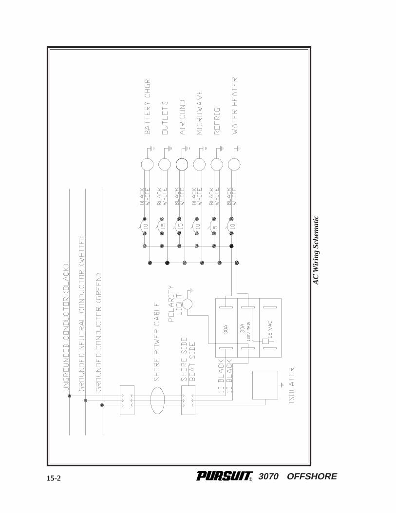
3070 OFFSHORE15-2
AC
Wir
ing
Sche
mat
ic
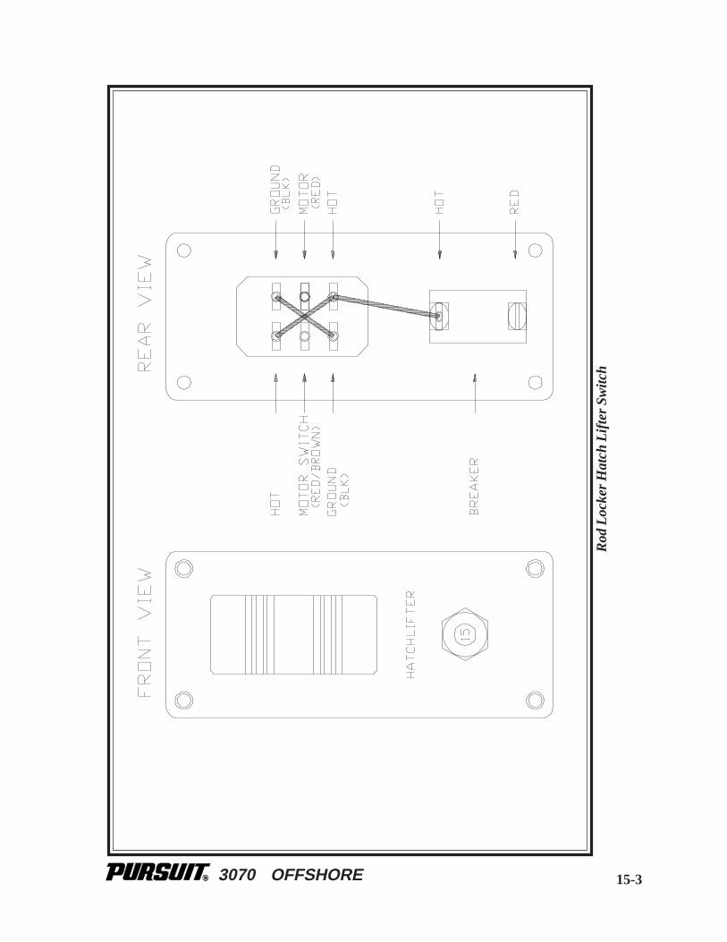
3070 OFFSHORE
Rod
Loc
ker
Hat
ch L
ifte
r Sw
itch
15-3

3070 OFFSHORE
Bat
tery
Cab
le R
outin
g
15-4
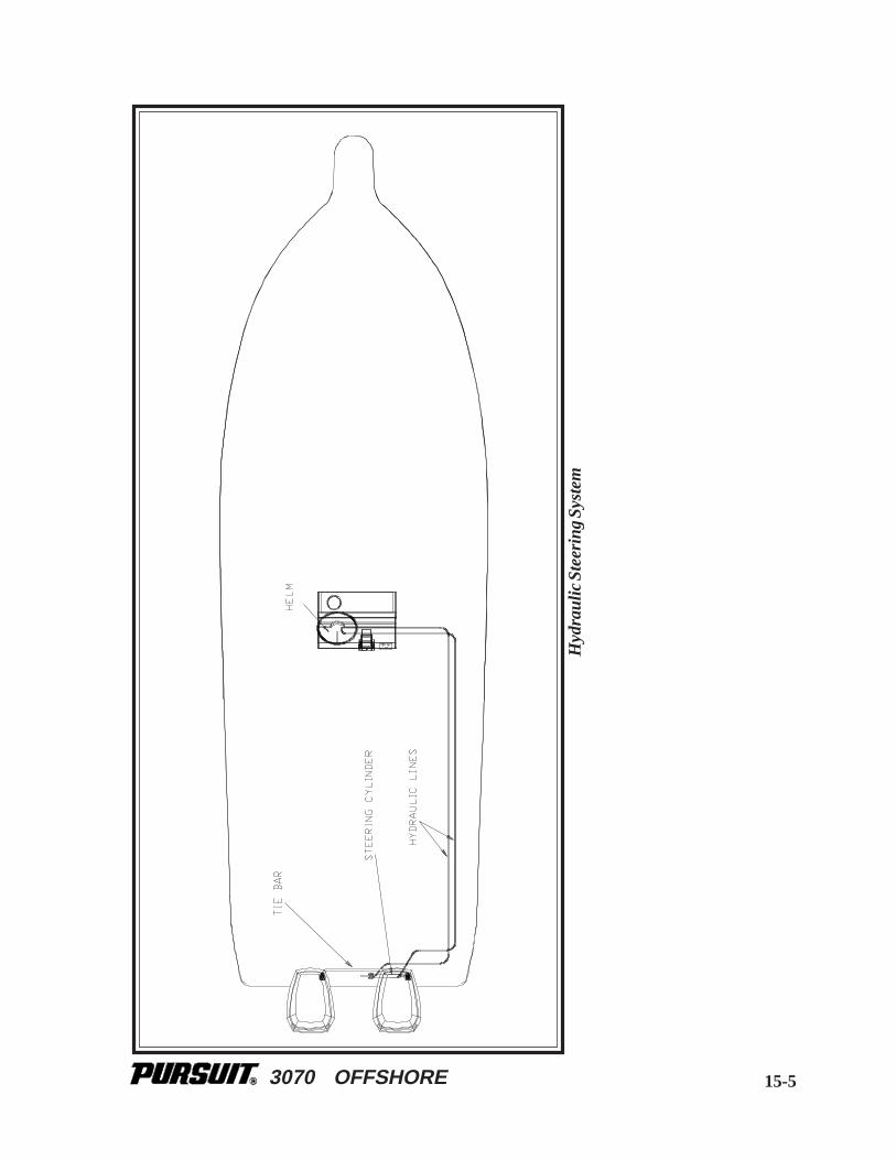
3070 OFFSHORE 15-5
Hyd
raul
ic S
teer
ing
Syst
em

3070 OFFSHORE
Con
trol
Cab
les
15-6

3070 OFFSHORE
Gen
erat
or
15-7

3070 OFFSHORE15-8
Fue
l Sys
tem
2-S
trok
e

3070 OFFSHORE 15-9
Fue
l Sys
tem
4-S
trok
e
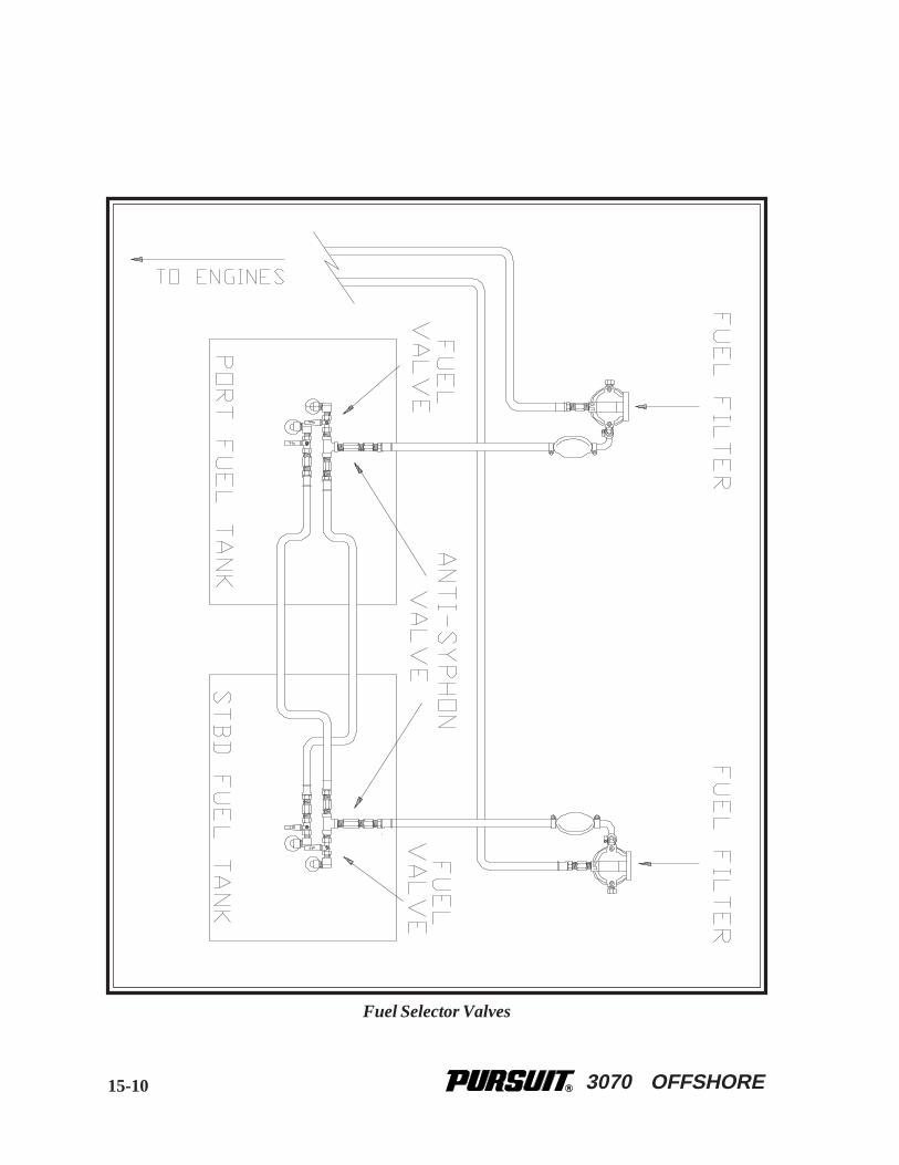
3070 OFFSHORE15-10
Fuel Selector Valves
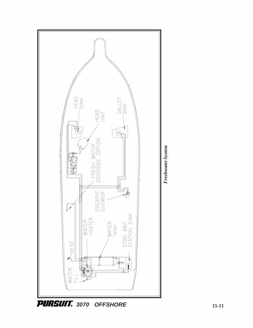
3070 OFFSHORE 15-11
Fre
shw
ater
Sys
tem
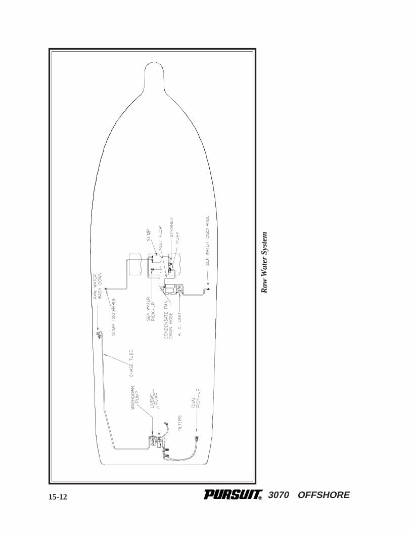
3070 OFFSHORE15-12
Raw
Wat
er S
yste
m
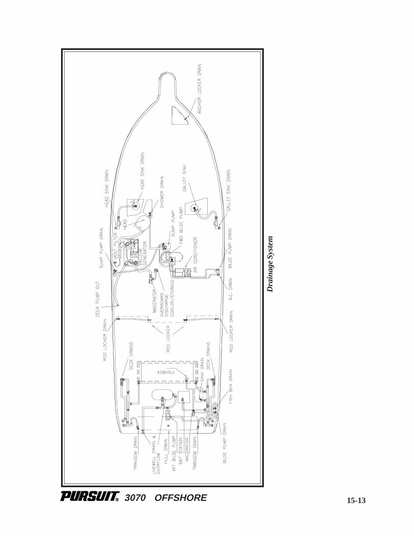
3070 OFFSHORE 15-13
Dra
inag
e Sy
stem
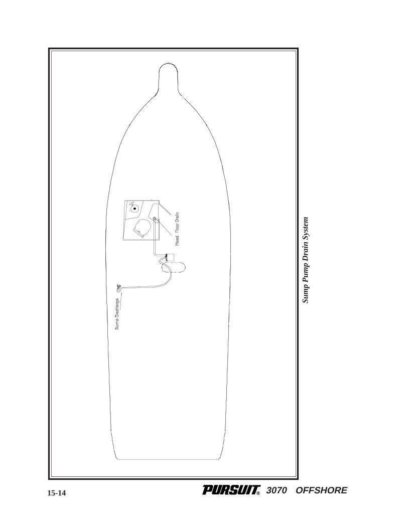
3070 OFFSHORE
Sum
p P
ump
Dra
in S
yste
m
15-14

3070 OFFSHORE
Air
Con
ditio
ning
Sys
tem
15-15
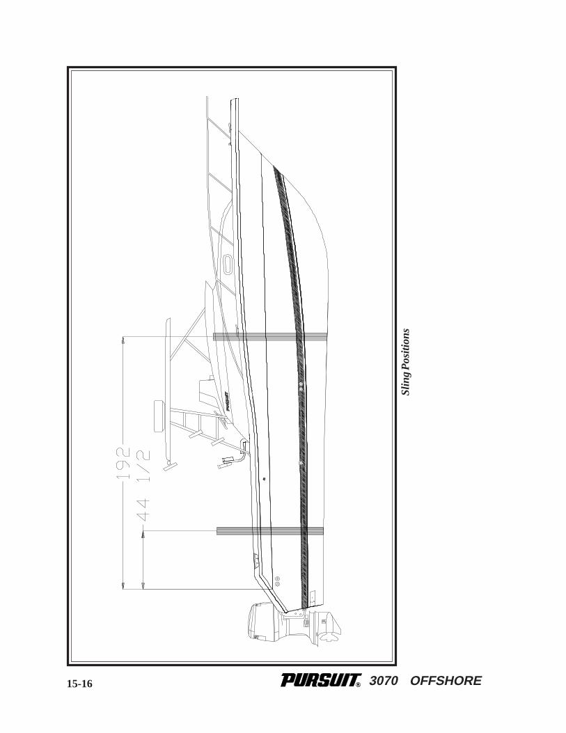
3070 OFFSHORE15-16
Slin
g P
ositi
ons

3070 OFFSHORE
Bun
k L
ocat
ions
15-17

3070 OFFSHORE15-18
Hal
f Tow
er P
late
Loc
taio
ns

3070 OFFSHORE
APPENDIX A:GLOSSARY OF TERMS
Aft: In, near, or toward the stern of a boat.
Aground: A boat stuck on the bottom.
Amidships: In or toward the part of a boat midway between the bow and stern.
Anchor: A specially shaped heavy metal device designed to dig efficiently into the bottom undera body of water and hold a boat in place.
Anchorage: An area specifically designated by governmental authorities in which boats mayanchor.
Ashore: On shore.
Astern: Behind the boat, to move backwards.
Athwartship: At right angles to the center line of the boat.
Barnacles: Small, hard-shelled marine animals which are found in salt water attached to pilings,docks and bottoms of boats.
Beam: The breadth of a boat usually measured at its widest part.
Bearing: The direction of an object from the boat, either relative to the boat's direction or tocompass degrees.
Berth: A bunk or a bed on a boat.
Bilge: The bottom of the boat below the flooring.
Bilge Pump: A pump that removes water that collects in the bilge.
Boarding: Entering or climbing into a boat.
Boarding Ladder: Set of steps temporarily fitted over the side of a boat to assist persons comingaboard.
A-1

3070 OFFSHORE
Boat Hook: Short shaft of wood or metal with a hook fitting at one end shaped to aid in extendingone’s reach from the side of the boat.
Bow: The front end of a boat's hull.
Bow Line: A line that leads forward from the bow of the boat.
Bow Rail: Knee high rails of solid tubing to aid in preventing people from falling overboard.
Bridge: The area from which a boat is steered and controlled.
Bridge Deck: A deck forward and usually above the cockpit deck.
Broach: When the boat is sideways to the seas and in danger of capsizing; a very dangeroussituation that should be avoided.
Bulkhead: Vertical partition or wall separating compartments of a boat.
Cabin: Enclosed superstructure above the main deck level.
Capsize: When a boat lays on its side or turns over.
Chock: A deck fitting, usually of metal, with inward curving arms through which mooring oranchor lines are passed so as to lead them in the proper direction both on board and off the boat.
Cleat: A deck fitting, usually of metal with projecting arms used for securing anchor and mooringlines.
Closed Cooling System: A separate supply of fresh water that is used to cool the engine andcirculates only within the engine.
Coaming: A vertical piece around the edges of cockpit, hatches, etc. to stop water on deck fromrunning below.
Cockpit: An open space, usually in the aft deck, outside of the cabin.
Companionway: Opening in the deck of a boat to provide access below.
Compartment: The interior of a boat divided off by bulkheads.
Cradle: A framework designed to support a boat as she is hauled out or stored.
Cutlass Bearing: A rubber bearing in the strut that supports the propeller shaft.
A-2

3070 OFFSHORE
Deck: The floor-like platform of a boat that covers the hull.
Displacement: The volume of water displaced by the hull. The displacement weight is the weightof this volume of water.
Draft: The depth of water a boat needs to float.
Dry Rot: A fungus attack on wood areas.
Dry-dock: A dock that can be pumped dry during boat construction or repair.
Electrical Ground: A connection between an electrical connector and the earth.
Engine Beds: Sturdy structural members running fore and aft on which the inboard engines aremounted.
EPIRB: Emergency Position Indicating Radio Beacon. Operates as a part of a worldwide satellitedistress system.
Even Keel: When a boat floats properly as designed.
Fathom: A measure of depth. One Fathom = 6 feet.
Fender: A soft object of rubber or plastic used to protect the topsides from scarring and rubbingagainst a dock or another vessel.
Fend off: To push or hold the boat off from the dock or another boat.
Flying Bridge: A control station above the level of the deck or cabin.
Flukes: The broad portions of an anchor which dig into the ground.
Fore: Applies to the forward portions of a boat near the bow.
Foundering: When a boat fills with water and sinks.
Freeboard: The height from the waterline to the lowest part of the deck.
Galley: The kitchen of a boat.
Grab Rail: Hand-hold fittings mounted on cabin tops or sides for personal safety when movingaround the boat, both on deck and below.
A-3

3070 OFFSHORE
Ground Tackle: A general term including anchors, lines, and other gear used in anchoring.
Grounds: A boat touches the bottom.
Gunwale: The upper edge of a boat’s side.
Hand Rail: Rail mounted on the boat, for grabbing with your hand, to steady you while walkingabout the boat.
Harbor: An anchorage which provides reasonably good protection for a boat, with shelter fromwind and sea.
Hatch: An opening in the deck with a door or lid to allow for access down into a compartmentof a boat.
Head: A toilet on a boat.
Heat Exchanger: Used to transfer the heat that is picked up by the closed cooling system to theraw cooling water.
Helm: The steering and control area of a boat.
Hull: The part of the boat from the deck down.
Inboard: A boat with the engine mounted within the hull of the boat. Also refers to the centerof the boat away from the sides.
Inboard/outboard: Also stern drive or I/O. A boat with an inboard engine attached to an outboarddrive unit.
Keel: A plate or timber plate running lengthwise along the center of the bottom of a boat.
Knot: Unit of speed indicating nautical miles per hour. 1 knot = 1 nautical mile per hour (1.15miles per hour). A nautical mile is equal to one minute of latitude: 6076 feet. Knots times 1.15equals miles per hour. Miles per hour times .87 equals knots.
Lay-up: To decommission a boat for the winter (usually in northern climates).
Leeward: The direction toward which the wind is blowing.
A-4
3070 OFFSHORE
Length On The Waterline (l.w.l.): A length measurement of a boat at the waterline from the sternto where the hull breaks the water near the bow.
Limber Hole: A passage cut into the lower edges of floors and frames next to the keel to allowbilge water to flow to the lowest point of the hull where it can be pumped overboard.
Line: The term used to describe a rope when it is on a boat.
Lists: A boat that inclines to port or starboard while afloat.
L.O.A.: Boat length overall.
Locker: A closet, chest or box aboard a boat.
Loran: An electronic navigational instrument which monitors the boat's position using signalsemitted from pairs of transmitting stations.
Lunch hook: A small light weight anchor typically used instead of the working anchor. Normallyused in calm waters with the boat attended.
Midships: The center of the boat.
Marina: A protected facility primarily for recreational small craft.
Marine Ways or Railways: Inclined planes at the water’s edge onto which boats are hauled.
Moored: A boat secured with cables, lines or anchors.
Mooring: An anchor permanently embedded in the bottom of a harbor that is used to secure a boat.
Nautical Mile: A unit of measure equal to one minute of latitude. (6076 feet)
Nun Buoy: A red or red-striped buoy of conical shape.
Outboard: A boat designed for an engine to be mounted on the transom. Also a term that refersto objects away from the center line or beyond the hull sides of a boat.
Pad Eye: A deck fitting consisting of a metal eye permanently secured to the boat.
Pier: A structure which projects out from the shoreline.
Pile or Piling: A long column driven into the bottom to which a boat can be tied.
A-5

3070 OFFSHORE
Pitching: The fore and aft rocking motion of a boat as the bow rises and falls.
Pitch: The measure of the angle of a propeller blade. Refers to the theoretical distance the boattravels with each revolution of the propeller.
P.F.D: Personal Flotation Device.
Port: The left side of the boat when facing the bow.
Porthole (port): The opening in the side of a boat to allow the admittance of light and air.
Propeller: A device having two or more blades that is attached to the engine and used forpropelling a boat.
Propeller Shaft: Shaft which runs from the back of the engine gear box, aft, through the stuffingbox, shaft log, struts, and onto which the propeller is attached.
Pyrotechnic Distress Signals: Distress signals that resemble the brilliant display of flares orfireworks.
Raw Water Cooled: Refers to an engine cooling system that draws sea water in through a hullfitting or engine drive unit, circulates the water in the engine, and then discharges it overboard.
Reduction Gear: Often combined with the reverse gear so that the propeller turns at a slower ratethan the engine.
Reverse Gear: Changes the direction of rotation of the propeller to provide thrust in the oppositedirection for stopping the boat or giving it sternway.
Roll: A boat’s sideways rotational motion in rough water.
Rope Locker: A locker, usually located in the bow of a boat, used for stowing the anchor line orchain.
Rubrail: Railing (often rubber or hard plastic) that runs along the boat’s sheer to protect the hullwhen coming alongside docks, piers, or other boats.
Rudder: A moveable flat surface that is attached vertically at or near the stern for steering.
Sea anchor: An anchor that does not touch the bottom. Provides drag to hold the bow in the mostfavorable position in heavy seas.
Scupper: An opening in the hull side or transom of the boat through which water on deck or in
A-6

3070 OFFSHORE
the cockpit is drained overboard.
Seacock: Safety valves installed just inside the thru-hull fittings and ahead of the piping or hoserunning from the fittings.
Shaft Log: Pipe through which the propeller shaft passes.
Sheer: The uppermost edge of the hull.
Sling: A strap which will hold the boat securely while being lifted, lowered, or carried.
Slip: A boat's berth between two pilings or piers.
Sole: The deck of a cockpit or interior cabin.
Spring Line: A line that leads from the bow aft or from the stern forward to prevent the boat frommoving ahead or astern.
Starboard: The right side of a boat when facing the bow.
Steerageway: Sufficient speed to keep the boat responding to the rudder or drive unit.
Stem: The vertical portion of the hull at the bow.
Stern: The rear end of a boat.
Stow: To pack away neatly.
Stringer: Longitudinal members fastened inside the hull for additional structural strength.
Strut: Mounted to the hull which supports the propeller shaft in place.
Strut Bearing: See “cutlass bearing.”
Stuffing Box: Prevents water from entering at the point where the propeller shaft passes throughthe shaft log.
Superstructure: Something built above the main deck level.
Swamps: When a boat fills with water from over the side.
Swimming Ladder: Much the same as the boarding ladder except that it extends down into thewater.
Taffrail: Rail around the rear of the cockpit.
A-7

3070 OFFSHORE
Thru-hull: A fitting used to pass fluids (usually water) through the hull surface, either above orbelow the waterline.
Topsides: The side skin of a boat between the waterline or chine and deck.
Transom: A flat stern at right angles to the keel.
Travel Lift: A machine used at boat yards to hoist boats out of and back into the water.
Trim: Refers to the boat's angle or the way it is balanced.
Trough: The area of water between the crests of waves and parallel to them.
Twin-Screw Craft: A boat with two propellers on two separate shafts.
Underway: When a boat moves through the water.
Wake: Disrupted water that a boat leaves astern as a result of its motion.
Wash: The flow of water that results from the action of the propeller or propellers.
Waterline: The plane of a boat where the surface of the water touches the hull when it is afloaton even keel.
Watertight Bulkhead: Bulkheads secured so tightly so as not to let water pass.
Wharf: A structure generally parallel to the shore.
Working Anchor: An anchor carried on a boat for most normal uses. Refers to the anchor usedin typical anchoring situations.
Windlass: A winch used to raise and lower the anchor.
Windward: Toward the direction from which the wind is coming.
Yacht Basin: A protected facility primarily for recreational small craft.
Yaw: When a boat runs off her course to either side.
A-8

3070 OFFSHORE
Appendix B:
HoursDate Dealer Service/Repairs
MAINTENANCE LOG
B-1
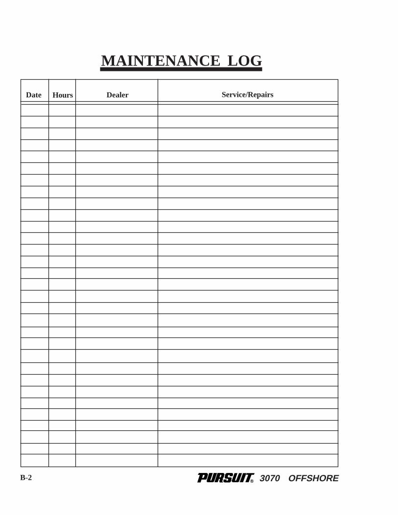
3070 OFFSHORE
HoursDate Dealer Service/Repairs
MAINTENANCE LOG
B-2

3070 OFFSHORE
HoursDate Dealer Service/Repairs
MAINTENANCE LOG
B-3

3070 OFFSHORE
HoursDate Dealer Service/Repairs
MAINTENANCE LOG
B-4

3070 OFFSHORE
HoursDate Dealer Service/Repairs
MAINTENANCE LOG
B-5

3070 OFFSHORE
HoursDate Dealer Service/Repairs
MAINTENANCE LOG
B-6
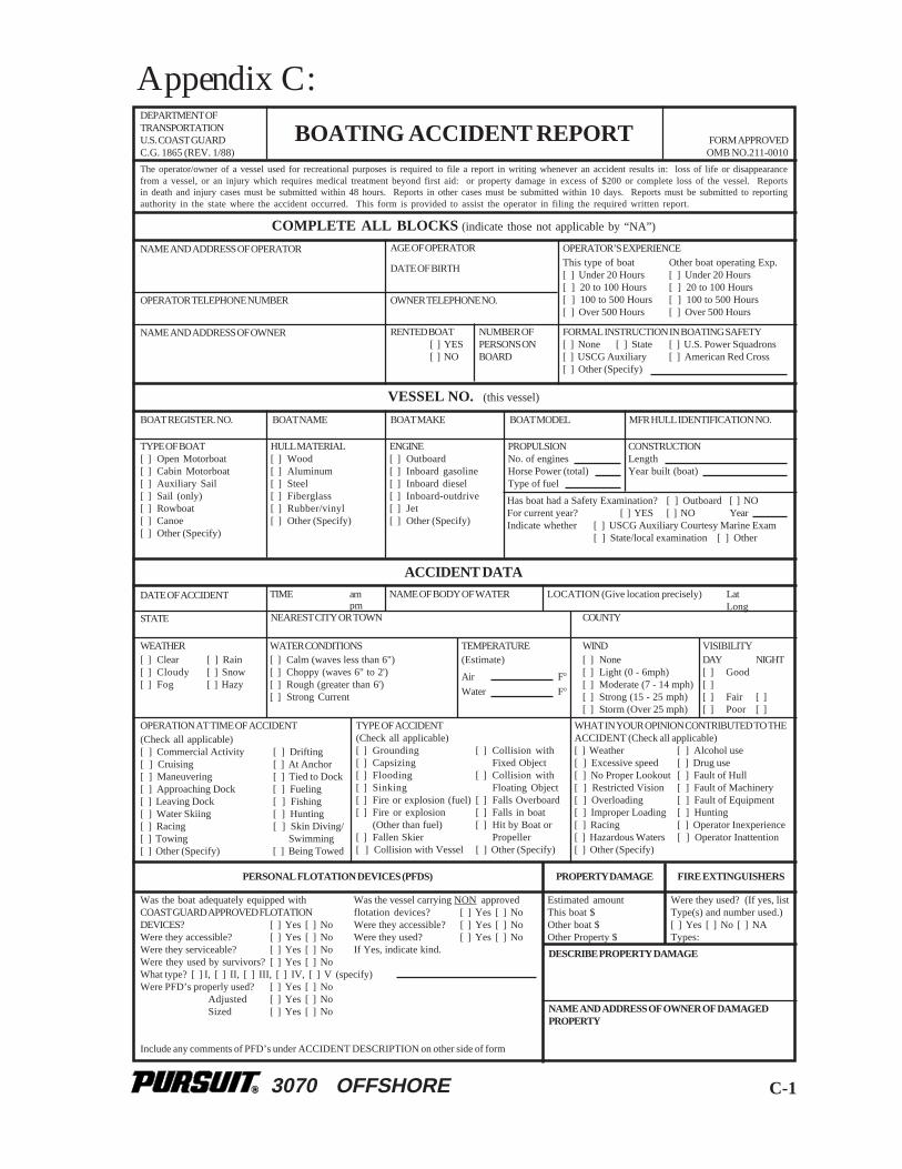
3070 OFFSHORE C-1
Appendix C:
BOATING ACCIDENT REPORT FORM APPROVEDOMB NO.211-0010
DEPARTMENT OFTRANSPORTATIONU.S. COAST GUARDC.G. 1865 (REV. 1/88)
The operator/owner of a vessel used for recreational purposes is required to file a report in writing whenever an accident results in: loss of life or disappearancefrom a vessel, or an injury which requires medical treatment beyond first aid: or property damage in excess of $200 or complete loss of the vessel. Reportsin death and injury cases must be submitted within 48 hours. Reports in other cases must be submitted within 10 days. Reports must be submitted to reportingauthority in the state where the accident occurred. This form is provided to assist the operator in filing the required written report.
COMPLETE ALL BLOCKS (indicate those not applicable by “NA”)
OPERATOR TELEPHONE NUMBER
NAME AND ADDRESS OF OPERATOR
NAME AND ADDRESS OF OWNER
AGE OF OPERATOR
DATE OF BIRTH
OWNER TELEPHONE NO.
RENTED BOAT[ ] YES[ ] NO
NUMBER OFPERSONS ONBOARD
OPERATOR’S EXPERIENCEThis type of boat Other boat operating Exp.[ ] Under 20 Hours [ ] Under 20 Hours[ ] 20 to 100 Hours [ ] 20 to 100 Hours[ ] 100 to 500 Hours [ ] 100 to 500 Hours[ ] Over 500 Hours [ ] Over 500 Hours
FORMAL INSTRUCTION IN BOATING SAFETY[ ] None [ ] State [ ] U.S. Power Squadrons[ ] USCG Auxiliary [ ] American Red Cross[ ] Other (Specify)
VESSEL NO. (this vessel)
BOAT REGISTER. NO. BOAT NAME BOAT MAKE BOAT MODEL MFR HULL IDENTIFICATION NO.
TYPE OF BOAT[ ] Open Motorboat[ ] Cabin Motorboat[ ] Auxiliary Sail[ ] Sail (only)[ ] Rowboat[ ] Canoe[ ] Other (Specify)
HULL MATERIAL[ ] Wood[ ] Aluminum[ ] Steel[ ] Fiberglass[ ] Rubber/vinyl[ ] Other (Specify)
PROPULSIONNo. of enginesHorse Power (total)Type of fuel
CONSTRUCTIONLengthYear built (boat)
Has boat had a Safety Examination? [ ] Outboard [ ] NOFor current year? [ ] YES [ ] NO YearIndicate whether [ ] USCG Auxiliary Courtesy Marine Exam
[ ] State/local examination [ ] Other
ACCIDENT DATA
DATE OF ACCIDENT TIME ampm
NAME OF BODY OF WATER LOCATION (Give location precisely) LatLong
STATE NEAREST CITY OR TOWN COUNTY
WEATHER[ ] Clear [ ] Rain[ ] Cloudy [ ] Snow[ ] Fog [ ] Hazy
WATER CONDITIONS[ ] Calm (waves less than 6")[ ] Choppy (waves 6" to 2')[ ] Rough (greater than 6')[ ] Strong Current
TEMPERATURE(Estimate)
Air F°Water F°
WIND[ ] None[ ] Light (0 - 6mph)[ ] Moderate (7 - 14 mph)[ ] Strong (15 - 25 mph)[ ] Storm (Over 25 mph)
VISIBILITYDAY NIGHT[ ] Good[ ][ ] Fair [ ][ ] Poor [ ]
ENGINE[ ] Outboard[ ] Inboard gasoline[ ] Inboard diesel[ ] Inboard-outdrive[ ] Jet[ ] Other (Specify)
OPERATION AT TIME OF ACCIDENT(Check all applicable)[ ] Commercial Activity [ ] Drifting[ ] Cruising [ ] At Anchor[ ] Maneuvering [ ] Tied to Dock[ ] Approaching Dock [ ] Fueling[ ] Leaving Dock [ ] Fishing[ ] Water Skiing [ ] Hunting[ ] Racing [ ] Skin Diving/[ ] Towing Swimming[ ] Other (Specify) [ ] Being Towed
TYPE OF ACCIDENT(Check all applicable)[ ] Grounding [ ] Collision with[ ] Capsizing Fixed Object[ ] Flooding [ ] Collision with[ ] Sinking Floating Object[ ] Fire or explosion (fuel) [ ] Falls Overboard[ ] Fire or explosion [ ] Falls in boat
(Other than fuel) [ ] Hit by Boat or[ ] Fallen Skier Propeller[ ] Collision with Vessel [ ] Other (Specify)
WHAT IN YOUR OPINION CONTRIBUTED TO THEACCIDENT (Check all applicable)[ ] Weather [ ] Alcohol use[ ] Excessive speed [ ] Drug use[ ] No Proper Lookout [ ] Fault of Hull[ ] Restricted Vision [ ] Fault of Machinery[ ] Overloading [ ] Fault of Equipment[ ] Improper Loading [ ] Hunting[ ] Racing [ ] Operator Inexperience[ ] Hazardous Waters [ ] Operator Inattention[ ] Other (Specify)
PERSONAL FLOTATION DEVICES (PFDS) PROPERTY DAMAGE FIRE EXTINGUISHERS
Estimated amountThis boat $Other boat $Other Property $
Were they used? (If yes, listType(s) and number used.)[ ] Yes [ ] No [ ] NATypes:
DESCRIBE PROPERTY DAMAGE
NAME AND ADDRESS OF OWNER OF DAMAGEDPROPERTY
Was the boat adequately equipped withCOAST GUARD APPROVED FLOTATIONDEVICES? [ ] Yes [ ] NoWere they accessible? [ ] Yes [ ] NoWere they serviceable? [ ] Yes [ ] NoWere they used by survivors? [ ] Yes [ ] NoWhat type? [ ] I, [ ] II, [ ] III, [ ] IV, [ ] V (specify)Were PFD’s properly used? [ ] Yes [ ] No
Adjusted [ ] Yes [ ] NoSized [ ] Yes [ ] No
Include any comments of PFD’s under ACCIDENT DESCRIPTION on other side of form
Was the vessel carrying NON approvedflotation devices? [ ] Yes [ ] NoWere they accessible? [ ] Yes [ ] NoWere they used? [ ] Yes [ ] NoIf Yes, indicate kind.

3070 OFFSHOREC-2
If more than 3 fatalities and/or injuries, attach additional form(s)
WAS VICTIM?[ ] Swimmer[ ] Non Swimmer
DATE OFBIRTH
ADDRESSNAME DEATH CAUSED BY[ ] Drowning[ ] Other[ ] DISAPPEARANCE
WAS PFD WORN?[ ] Yes [ ] NoWhat Type?
WAS VICTIM?[ ] Swimmer[ ] Non Swimmer
DATE OFBIRTH
ADDRESSNAME DEATH CAUSED BY[ ] Drowning[ ] Other
WAS PFD WORN?[ ] Yes [ ] NoWhat Type?
WAS VICTIM?[ ] Swimmer[ ] Non Swimmer
DATE OFBIRTH
ADDRESSNAME DEATH CAUSED BY[ ] Drowning[ ] Other
WAS PFD WORN?[ ] Yes [ ] NoWhat Type?
[ ] DISAPPEARANCE
[ ] DISAPPEARANCE
ADDRESSNAME
ADDRESSNAME
ADDRESSNAME
NATURE OF INJURYDATE OFBIRTH
DATE OFBIRTH
DATE OFBIRTH
NATURE OF INJURY
NATURE OF INJURY
MEDICAL TREATMENT
MEDICAL TREATMENT
MEDICAL TREATMENT
DESCRIBE WHAT HAPPENED (Sequence of events. Include Failure of Equipment. If diagram is needed, attach separately. Continue on additional sheetsif necessary. Include any information regarding the involvement of alcohol and/or drugs in causing or contributing to the accident. Include any descriptiveinformation about the use of PFD's.)
INJURED
VESSEL NO. 2 (if more than 2 vessels, attach additional form (s)
DECEASED
ACCIDENT DESCRIPTION
Name of Owner
Telephone Number
Name of Operator Address
Address
AddressName
Name
Name
Address
Address
Boat Name
Boat Number
Telephone Number
Telephone Number
Telephone Number
Telephone Number
Date Submitted
Date Received
Reviewed By
AddressSIGNATURE
QUALIFICATION (Check One)[ ] Operator [ ] Owner [ ] Investigator [ ] Other
Causes based on (check one)[ ] This report [ ] Investigation and this report[ ] Investigation [ ] Could not be determinedPrimary Cause of Accident Secondary Cause of Accident
Name of Reviewing Office(do not use) - FOR REPORTING AUTHORITY REVIEW (use agency date stamp)
WITNESSES
WITNESSES
BOATING ACCIDENT REPORT

3070 OFFSHORE
Contents
SAFETY INFORMATIONBOAT INFORMATIONIMPORTANT INFORMATIONOWNER'S/OPERATOR'S RESPONSIBILITIESTABLE OF CONTENTSChapter 1: PROPULSION SYSTEM 1.1 General1.2 Drive System Corrosion1.3 Engine Lubrication1.4 Engine Cooling System1.5 Propellers1.6 Engine InstrumentationChapter 2:HELM CONTROL SYSTEMS2.1 General2.2 Engine Throttle and Shift Controls2.3 Neutral Safety Switch2.4 Engine Power Tilt and Trim2.5 Engine Stop Switch2.6 Steering System2.7 Trim Tabs2.8 Control Systems MaintenanceChapter 3:FUEL SYSTEM3.1 General3.2 Outboard Fuel System3.3 Diesel Generator Fuel System (Optional)3.4 Fueling Instructions3.5 Fuel System MaintenanceChapter 4:ELECTRICAL SYSTEM4.1 General4.2 12-Volt System4.3 110-Volt System4.4 Electrical System Maintenance

3070 OFFSHORE
Chapter 5:FRESHWATER SYSTEM5.1 General5.2 Freshwater System Operation5.3 Water Heater 5.4 Shore Water Connection (Optional)5.5 Shower Operation5.6 Freshwater System MaintenanceChapter 6:RAW WATER SYSTEM6.1 General6.2 High Pressure Washdown 6.3 Livewell 6.4 Air Conditioning Pump6.5 Raw Water System MaintenanceChapter 7:DRAINAGE SYSTEMS7.1 General7.2 Cockpit Drains7.3 Hard-Top Drains 7.4 Bilge Drainage7.5 Fishbox, Cooler and Storage Compartment Drains7.6 Water System Drains7.7 Cabin Drains7.8 Rope Locker Drains7.9 Drainage System MaintenanceChapter 8:VENTILATION SYSTEM8.1 Cabin Ventilation8.2 Windshield Ventilation 8.3 Carbon Monoxide and Proper Ventilation 8.4 Bilge Compartment Ventilation8.5 MaintenanceChapter 9:EXTERIOR EQUIPMENT9.1 Deck9.2 Hull9.3 Cockpit Chapter 10:
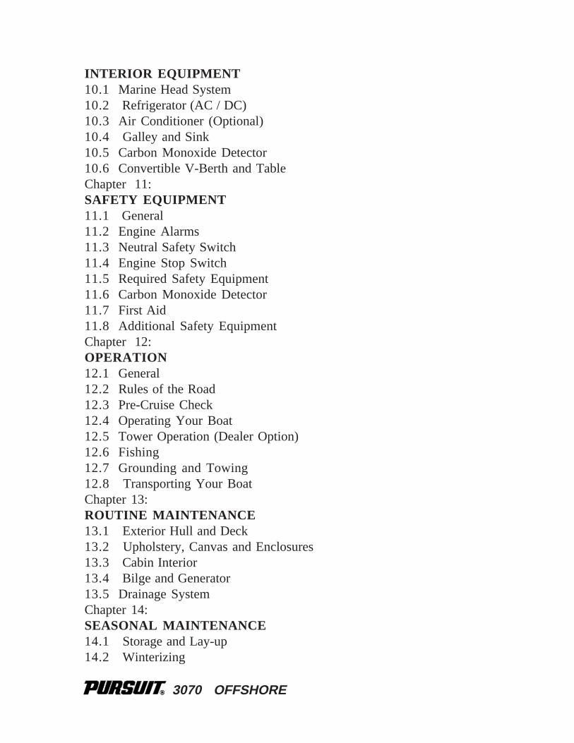
3070 OFFSHORE
INTERIOR EQUIPMENT10.1 Marine Head System10.2 Refrigerator (AC / DC)10.3 Air Conditioner (Optional)10.4 Galley and Sink10.5 Carbon Monoxide Detector10.6 Convertible V-Berth and TableChapter 11:SAFETY EQUIPMENT11.1 General11.2 Engine Alarms11.3 Neutral Safety Switch11.4 Engine Stop Switch11.5 Required Safety Equipment11.6 Carbon Monoxide Detector11.7 First Aid11.8 Additional Safety EquipmentChapter 12:OPERATION12.1 General12.2 Rules of the Road12.3 Pre-Cruise Check12.4 Operating Your Boat12.5 Tower Operation (Dealer Option)12.6 Fishing12.7 Grounding and Towing12.8 Transporting Your BoatChapter 13:ROUTINE MAINTENANCE13.1 Exterior Hull and Deck13.2 Upholstery, Canvas and Enclosures13.3 Cabin Interior13.4 Bilge and Generator13.5 Drainage SystemChapter 14:SEASONAL MAINTENANCE14.1 Storage and Lay-up 14.2 Winterizing
3070 OFFSHORE
14.3 RecommissioningChapter 15:SCHEMATICS12-Volt DC Wiring SchematicAC Wiring SchematicRod Locker Hatch Lifter SwitchBattery Cable RoutingHydraulic Steering System Control CablesGeneratorFuel System 2-StrokeFuel System 4-StrokeFuel Selector ValvesFreshwater System Raw Water SystemDrainage SystemSump Pump Drain SystemAir Conditioning SystemSling Positions Bunk LocationsHalf Tower Plate LocationsAPPENDIX A:GLOSSARY OF TERMSAppendix B:MAINTENANCE LOGAppendix C:BOATING ACCIDENT REPORT