309246j, system hvlp turbine sprayers - graco.com · 309246 5 component identification and function...
TRANSCRIPT

309246Rev. J
System 4900� Shown7947A
OWNER’S MANUAL
System HVLP Turbine SprayersImportant Safety InstructionsRead all warnings and instructions in thismanual. Save these instructions.
120V AC 50/60 Hz
System 2500� Sprayer with Two-Stage TurbineModel 8260005 psi (34 kPa, 0.3 bar) Maximum Working Pressure
System 3800� Sprayer with Three-Stage Turbine
Model 8260016 psi (41 kPa, 0.4 bar) Maximum Working Pressure
System 4900� Sprayer with Four-Stage Turbine
Model 8260048 psi (55 kPa, 0.5 bar) Maximum Working Pressure
Model descriptions are in Turbine Components Table on page 4.
Related ManualsSystem ProCart� 309247. . . . . . . . . . . . . . . . . . . . . . . . HVLP Turbine Gun 309205. . . . . . . . . . . . . . . . . . . . . . .
GRACO INC. P.O. BOX 1441 MINNEAPOLIS, MN 55440–1441�COPYRIGHT 2000, GRACO INC.
Graco Inc. is registered to I.S. EN ISO 9001
2 309246
Table of ContentsWarnings 2. . . . . . . . . . . . . . . . . . . . . . . . . . . . . . . . . . . . . General Information 4. . . . . . . . . . . . . . . . . . . . . . . . . . . . Component Identification and Function 5. . . . . . . . . . . . Setup 6. . . . . . . . . . . . . . . . . . . . . . . . . . . . . . . . . . . . . . . . . Shutdown 10. . . . . . . . . . . . . . . . . . . . . . . . . . . . . . . . . . . . Maintenance 11. . . . . . . . . . . . . . . . . . . . . . . . . . . . . . . . . . Troubleshooting 13. . . . . . . . . . . . . . . . . . . . . . . . . . . . . . . Repair 14. . . . . . . . . . . . . . . . . . . . . . . . . . . . . . . . . . . . . . . Parts Drawing 16. . . . . . . . . . . . . . . . . . . . . . . . . . . . . . . . . Parts List 17. . . . . . . . . . . . . . . . . . . . . . . . . . . . . . . . . . . . . Accessories 18. . . . . . . . . . . . . . . . . . . . . . . . . . . . . . . . . . Specifications 21. . . . . . . . . . . . . . . . . . . . . . . . . . . . . . . . . Graco Standard Warranty 22. . . . . . . . . . . . . . . . . . . . . . Phone Number 22. . . . . . . . . . . . . . . . . . . . . . . . . . . . . . . .
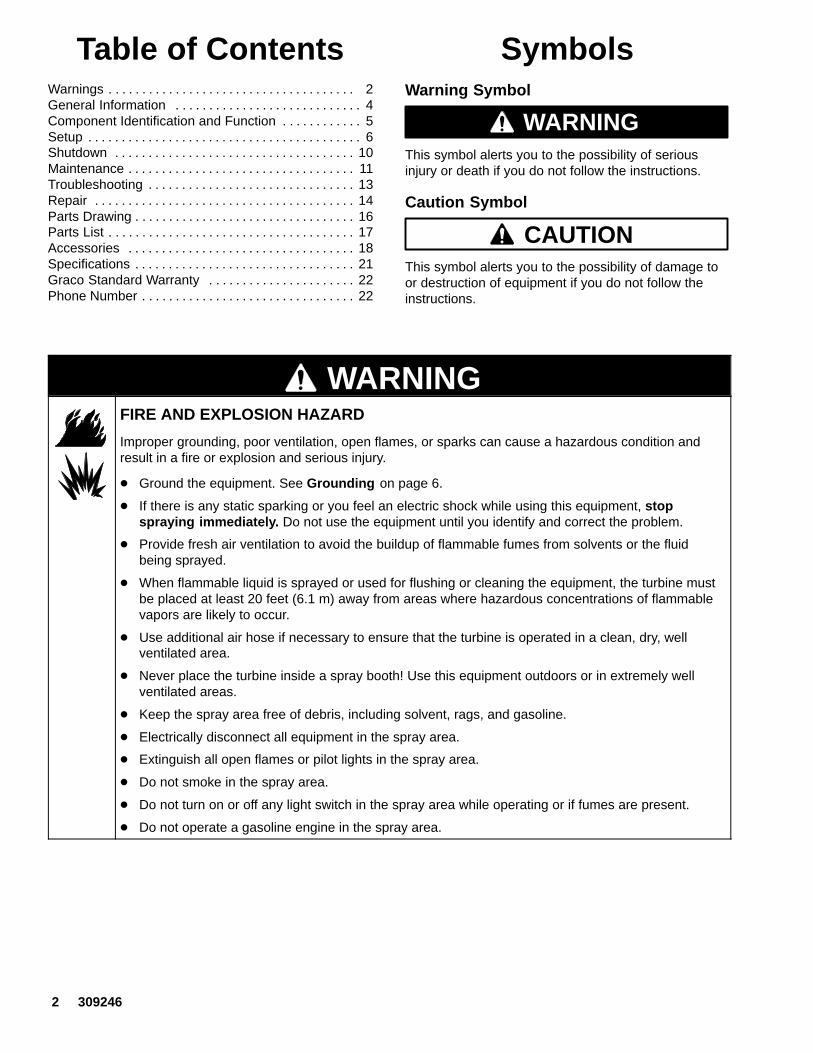
SymbolsWarning Symbol
WARNINGThis symbol alerts you to the possibility of seriousinjury or death if you do not follow the instructions.
Caution Symbol
CAUTIONThis symbol alerts you to the possibility of damage toor destruction of equipment if you do not follow theinstructions.
WARNINGFIRE AND EXPLOSION HAZARD
Improper grounding, poor ventilation, open flames, or sparks can cause a hazardous condition andresult in a fire or explosion and serious injury.
� Ground the equipment. See Grounding on page 6.
� If there is any static sparking or you feel an electric shock while using this equipment, stopspraying immediately. Do not use the equipment until you identify and correct the problem.
� Provide fresh air ventilation to avoid the buildup of flammable fumes from solvents or the fluidbeing sprayed.
� When flammable liquid is sprayed or used for flushing or cleaning the equipment, the turbine mustbe placed at least 20 feet (6.1 m) away from areas where hazardous concentrations of flammablevapors are likely to occur.
� Use additional air hose if necessary to ensure that the turbine is operated in a clean, dry, wellventilated area.
� Never place the turbine inside a spray booth! Use this equipment outdoors or in extremely wellventilated areas.
� Keep the spray area free of debris, including solvent, rags, and gasoline.
� Electrically disconnect all equipment in the spray area.
� Extinguish all open flames or pilot lights in the spray area.
� Do not smoke in the spray area.
� Do not turn on or off any light switch in the spray area while operating or if fumes are present.
� Do not operate a gasoline engine in the spray area.

309246 3
WARNING
INSTRUCTIONS
EQUIPMENT MISUSE HAZARD
Equipment misuse can cause the equipment to rupture or malfunction and result in serious injury.
� This equipment is for professional use only.
� Read all instruction manuals, tags, and labels before you operate the equipment.
� Use the equipment only for its intended purpose. If you are not sure, call your Graco distributor.
� Do not alter or modify this equipment. Use only genuine Graco parts.
� Check equipment daily. Repair or replace worn or damaged parts immediately.
� Do not exceed the maximum working pressure of the lowest-rated system component.System 2500� turbine has a working pressure of 5 psi (0.3 bar, 34 kPa).System 3800� turbine has a working pressure of 6 psi (0.4 bar, 41 kPa). System 4900� turbine has a working pressure of 8 psi (0.5 bar, 55 kPa).
� Use fluids and solvents which are compatible with the equipment wetted parts. See Specificationson page 21 for wetted parts information.
� Do not use hoses to pull equipment.
� Route hoses away from traffic areas, sharp edges, moving parts, and hot surfaces. Do not exposeGraco hoses to temperatures above 82�C (180�F) or below –40�C (–40�F).
� Wear hearing protection when operating this equipment.
� Do not lift pressurized equipment.
� Comply with all applicable local, state, and national fire, electrical, and safety regulations.
� Do not point the gun at anyone or at any part of the body.
� Do not put your hand or fingers over the gun fluid nozzle.
� Do not stop or deflect leaks with your hand, body, glove or rag.
� Do not “blow back” fluid; this is not an air spray system.
� Follow the Pressure Relief Procedure on page 10 if the fluid nozzle clogs and before you clean,check, or service the equipment.
� Tighten all fluid connections before you operate the equipment.
� Check the hoses, tubes, and couplings daily. Replace worn or damaged parts immediately.
TOXIC FLUID HAZARD
Hazardous fluid or toxic fumes can cause serious injury or death if splashed in the eyes or on the skin,inhaled, or swallowed.
� Know the specific hazards of the fluid you are using.
� Store hazardous fluid in an approved container. Dispose of hazardous fluid according to all local,state, and national guidelines.
� Always wear protective eyewear, gloves, clothing and respirator as recommended by the fluid andsolvent manufacturer.
� Do not use 1,1,1-trichloroethane, methylene chloride, other halogenated hydrocarbon solvents, orfluids containing such solvents in the turbine spray system, which contains aluminum and/orgalvanized-coated parts. Such use could result in a serious chemical reaction, with the possibilityof explosion, which could cause death, serious injury, and/or substantial property damage.

4 309246
General InformationSystem HVLP Turbine Sprayers
The System 2500�, 3800�, and 4900� Sprayer,System ProCart�, and HVLP–Turbine Gun can spraymost coatings or finishes currently being used forautomotive refinish, industrial, aerospace, marine,wood, plastic, and architectural applications.
To produce high-quality paint finishes, the spray guntypically utilizes inbound air pressure of 5 psi (0.3 bar,34 kPa) for System 2500�; 6 psi (0.4 bar, 41 kPa) forSystem 3800�; and 8 psi (0.5 bar, 55 kPa) forSystem 4900�. A cone of air, produced by the gun,carries and directs the paint from the gun to thesurface, minimizing overspray and increasing transferefficiency. This enables painters to comply with newclean air laws that are designed to reduce VOC(volatile organic compounds) emissions, eases paintapplication by requiring fewer paint passes to obtaincoverage, and saves on both material and clean-uptime.
See the HVLP–Turbine Gun manual 309205 for moreinformation on the operation and use of the turbinespray gun.
Unpacking Turbine Sprayer
Unpack the turbine sprayer from the shipping carton,and inspect for any possible shipping damage. If thereis any damage, call your distributor.
Turbine Sprayer Configurations
The turbine sprayers come in the following basicconfigurations:
� System 2500� two-stage HVLP turbine sprayer
� System 3800� three-stage HVLP turbine sprayer
� System 4900� four-stage HVLP turbine sprayer
System HVLP Turbine Sprayer Components Table
System Model 30-ft (9 m) HoseGun /
Fluid Set Extra/Fluid Sets
2500 826000 241413 244117 non–bleeder style cup gun/244124 (#3) fluid set
none
3800 826001 241413 244117 non–bleeder style cup gun/244124 (#3) fluid set
244125 (#4)244126 (#5)
4900 826004 241413 244117 non–bleeder style cup gun/244124 (#3) fluid set
244123 (#2)244125 (#4)244126 (#5)244127 (#6)

309246 5
Component Identification and Function
7947A
B
E
G
A
DC
H
F
Fig. 1
JK
L
A Air outlet Connection for air supply to HVLP–Turbine Guns (System 4900� unitsinclude quick connector)
B Power switch ON/OFF switch for turbine sprayer and rear outlet
C Storage compartment Provides storage for fluid set components
D Handle Folds flat for minimum storage space
E Cover Houses air filter and provides dual air flow to motor and turbine/ can belock-mounted on compressor/cart
F Air filters (pre-filter and main) Provide filtered air for HVLP–Turbine Gun and turbine motor
G Two-speed switch Allows two-speed operation of turbine sprayer motor (used on System4900� units)
H Air filter indicator light Indicates air filter performance and maintenance (used on System3800� and System 4900� units)
J Connector and power cord Provides power for turbine sprayer (power cord provided with turbine)
K Auxiliary power outlet Switched power outlet for System ProCart� or other accessory (usedon System 3800� and System 4900� units)
L Resettable circuit breaker Provides protection for turbine motor and cart

6 309246
SetupGrounding
WARNINGImproper installation or alteration of the groundingplug will result in a risk of electric shock, fire orexplosion that could cause serious injury or death.
This equipment requires a 120V AC, 60 Hz, 15A circuitwith a grounding receptacle. See Fig. 2.
Fig. 2
grounding prong
grounded outlets
Extension cord must be 3-wire, 12 AWG, 50 ft (15 m)or shorter.
Do not alter the ground prong or use an adapter.
Setup/Use Options
System HVLP Turbine Sprayers have a variety of useroptions. See Fig. 3.
� See the System ProCart� manual 309247 forinformation on compressor/cart setup andoperation.
� See the HVLP–Turbine Gun manual 309205 forinformation on gun setup and operation.
Prepare the Fluid
� Always strain the fluid before you spray; thisincludes color, reducer, and hardeners if used.
� When using a System HVLP Turbine Sprayer use aslower-drying reducer or thinner to compensate forthe faster drying time caused by the warm air of theturbine. Do not over reduce.
CAUTIONThe performance of the turbine sprayer varies withthe viscosity of the material and the length of thehose. Keep the hose short to prevent pressure drop.
Paint Reduction — Automotive Type Finishes
Reduce and catalyze all paint to manufacturer’sspecifications. To compensate for the faster dryingtime of turbine systems, use a reducer that is one stepslower than what is used for conventional air spray.
Paint Reduction — Industrial or DomesticCoatings
Reduce and catalyze all paint to manufacturer’sspecifications. If no reductions are given, firstthoroughly mix the fluid to be sprayed. Then graduallymix in the proper reducer, testing the fluid until youhave the correct spraying consistency.
To test the consistency, remove the stir stick from thethinned paint. When the paint stream running off thestir stick breaks into droplets, the first few drops shouldbe about one second apart.
C
A
Fig. 3
F
B
X
AG
Y
C
X
E
Y
H G
J K
E
D
X
Dcup-over option
(see manual 309205)
cup setup for spray gun
System 4900� Turbine
21/2-gallon remote pressure pot
tocompressor/cart
remote pressure pot setup for spray gun
ZY
JKHG
F
4958C
to compressor
2-quart remote pressure pot
ti7064a
309246 7
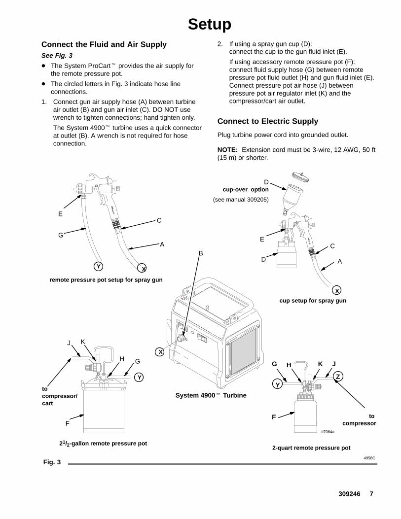
SetupConnect the Fluid and Air SupplySee Fig. 3
� The System ProCart� provides the air supply forthe remote pressure pot.
� The circled letters in Fig. 3 indicate hose lineconnections.
1. Connect gun air supply hose (A) between turbineair outlet (B) and gun air inlet (C). DO NOT usewrench to tighten connections; hand tighten only.
The System 4900� turbine uses a quick connectorat outlet (B). A wrench is not required for hoseconnection.
2. If using a spray gun cup (D):connect the cup to the gun fluid inlet (E).
If using accessory remote pressure pot (F):connect fluid supply hose (G) between remotepressure pot fluid outlet (H) and gun fluid inlet (E).Connect pressure pot air hose (J) betweenpressure pot air regulator inlet (K) and thecompressor/cart air outlet.
Connect to Electric Supply
Plug turbine power cord into grounded outlet.
NOTE: Extension cord must be 3-wire, 12 AWG, 50 ft(15 m) or shorter.

8 309246
SetupFill the Cup or Remote Pressure Pot
Spray Gun Cup
WARNINGThe spray gun cup is pressurized by the gun’s airsupply. To reduce the risk of serious injury frompressurized fluid or accidental spray from the gun,always turn off the air supply to the gun before youremove the spray gun cup.
Only fill the cup 3/4 full to help keep the air pressuretube clean, then install the cover. The under-cup coverhas a latch (H) to secure it to the cup. The over-cup (J)has threads that keep the lid in place when tightened inplace on the cup.
Fig. 4
02845
H J
Accessory Remote Pressure Pot
WARNINGThe accessory remote pressure pots remain pres-surized until pressure is manually relieved. Toreduce the risk of serious injury from pressurizedfluid or accidental spray from the gun, alwaysrelieve pressure in the pressure pot before youloosen or remove the cover.
1. Relieve remote pressure pot pressure as follows(see Fig. 5):
a. Turn off air supply to pressure pot.
b. 21/2-gallon remote pressure pot: Pull pressure relief valve ring (206c) untilpressure is completely relieved.
2-quart remote pressure pot: Turn pressure relief knob (113). Wait untilpressure is completely relieved before youremove cover. Close knob.
Fig. 58069A
206c
113
02882A
21/2 gallon 2 quart
2. Remove pressure pot cover and fill. Secure cover.
NOTE: 2-quart remote pressure pot only:Lightly coat the cover threads with petroleum jelly.
CAUTIONIf the 2-quart remote pressure pot is accidentallytipped over or held at too great of an angle, fluid mayleak into the air regulator and cause damage. Takeprecautions to avoid this. If fluid does get into theregulator, clean it immediately.

309246 9
SetupPrepare Surface to be Sprayed
To get proper adhesion, make sure surface iscompletely clean.
Operating System HVLP Turbine Sprayer
WARNINGSparks can be expected in the normal operation ofthe turbine motor. These sparks can ignite fumesfrom flammable liquids, dust particles, and otherflammable substances in the spray area. This cancause serious injury and property damage. Be sureto follow the precautions below:
� When flammable liquid is sprayed or used forflushing or cleaning equipment, the turbine mustbe placed at least 20 feet (6.1 m) away fromareas where hazardous concentrations offlammable vapors are likely to occur.
� Use additional air hose if necessary to ensurethat the turbine is operated in a clean, dry, wellventilated area.
� Never place the turbine inside a spray booth!Use this equipment outdoors or in extremelywell ventilated areas.
� Avoid all ignition sources such as: static elec-tricity from plastic drop cloths, open flames likepilot lights, hot objects like cigarettes, arcs fromconnecting or disconnecting power cords, andturning light switches on and off. Extinguish orremove all sources of ignition.
1. Turn turbine ON a few minutes before spraying toallow warm-up.
NOTE: When the turbine is not in use for an extendedperiod of time, turn it off. The turbine does not shut offautomatically.
2. Be sure turbine filter is clean before operating. Seepage 11 to check and clean filter.
NOTE: To adjust the spray gun pattern, see theHVLP–Turbine Gun manual 309205.
System ProCart� Cold Weather Operation
The System ProCart� uses a diaphragm compressor.A new diaphragm may be stiff in cold weather. If coldenough, the diaphragm is too stiff to allow thecompressor motor to start (the unit hums). If thisoccurs, follow these steps:
1. Turn turbine and compressor OFF.
2. Unplug turbine from power source.
3. Pinch and remove filter by hand. Clean or replaceif dirty.
4. Hand spin cooling fan on compressor for a fewrevolutions.
5. Reinstall filter.
6. Plug in turbine.
7. Turn turbine and compressor ON. If necessary,repeat procedure.
10 309246
ShutdownPressure Relief Procedure
WARNINGPRESSURIZED EQUIPMENT HAZARD
The equipment stays pressurized until pressure ismanually relieved. To reduce the risk of a seriousinjury from pressurized fluid, accidental spray fromthe gun, or splashing fluid, follow the PressureRelief Procedure whenever you
� Are instructed to relieve the pressure� Stop spraying� Check or service any of the system equipment� Install or clean the fluid nozzles
1. Turn off air supply to gun.
2. Turn off turbine sprayer.
WARNINGThe turbine hose outlet may be hot. Carefully checkthe hose end before you remove the hose.
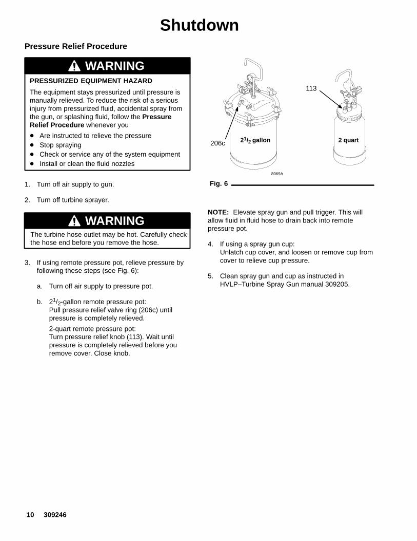
3. If using remote pressure pot, relieve pressure byfollowing these steps (see Fig. 6):
a. Turn off air supply to pressure pot.
b. 21/2-gallon remote pressure pot: Pull pressure relief valve ring (206c) untilpressure is completely relieved.
2-quart remote pressure pot: Turn pressure relief knob (113). Wait untilpressure is completely relieved before youremove cover. Close knob.
Fig. 6
8069A
206c
113
21/2 gallon 2 quart
NOTE: Elevate spray gun and pull trigger. This willallow fluid in fluid hose to drain back into remotepressure pot.
4. If using a spray gun cup:Unlatch cup cover, and loosen or remove cup fromcover to relieve cup pressure.
5. Clean spray gun and cup as instructed inHVLP–Turbine Spray Gun manual 309205.

309246 11
MaintenanceDaily
The System HVLP Turbine Sprayers are lifetimelubricated. The only maintenance required is filtercleaning and replacement.
The turbine filter must be clean at all times to providesufficient air flow to cool motor and atomize the fluid.Check turbine pre-filter (22) daily for cleanliness.Check the main paper filter (21) weekly, minimum.Clean as necessary.
NOTE: To check filter, turn on turbine and place pieceof paper against pre-filter. If air intake holds paper inplace, filter is okay.
System 3800� and System 4900� models have anair filter indicator light on the front panel. If the filter isgood the light is out. If the filter is clogged or has lowairflow the light will come on as in Fig. 7 below.
Fig. 78049A
To clean filter:
1. Turn off and unplug turbine.
2. Loosen four thumbscrews (16), and remove filterretainer (15) and pre-filter (22). See Fig. 8.
3. Remove main filter (21) and clean by using one ofthe following three methods:
� Tap filter gently on flat surface, dirty sidedown.
CAUTIONTo prevent damage to filter, do not use compressedair on a wet filter.
� Direct compressed air (100 psi [7 bar, 70 kPa]maximum) through filter panel in oppositedirection of arrows on side of filter (from theclean side to the dirty side).
� Soak filter for 15 minutes in water and milddetergent. Rinse filter until clean. Air dry. Donot use compressed air on damp or wet filter.
WARNINGTo avoid damage to the turbine and possible elec-tric shock, never install a damp filter in the turbine.
CAUTIONTo keep out dirt, do not operate the turbine sprayerwithout both filters installed.
Fig. 803072
16
21
22
15
20
1
Weekly
Check hose for cracks, leaks, and holes. Replace ifnecessary.
Annually or Every 600 Hours, WhicheverComes First
Replace motor brushes 600 hours after turbine sprayeroperation. If brushes are not replaced, motor failurewill occur.
NOTE: It is recommended that an authorized servicecenter perform the motor brush replacement procedureon page 14.

12 309246
Notes
309246 13
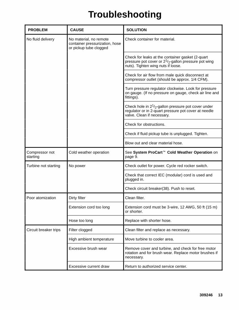
TroubleshootingPROBLEM CAUSE SOLUTION
No fluid delivery No material, no remotecontainer pressurization, hoseor pickup tube clogged
Check container for material.
Check for leaks at the container gasket (2-quartpressure pot cover or 21/2-gallon pressure pot wingnuts). Tighten wing nuts if loose.
Check for air flow from male quick disconnect atcompressor outlet (should be approx. 1/4 CFM).
Turn pressure regulator clockwise. Look for pressureon gauge. (If no pressure on gauge, check air line andfittings).
Check hole in 21/2-gallon pressure pot cover underregulator or in 2-quart pressure pot cover at needlevalve. Clean if necessary.
Check for obstructions.
Check if fluid pickup tube is unplugged. Tighten.
Blow out and clear material hose.
Compressor notstarting
Cold weather operation See System ProCart� Cold Weather Operation onpage 9.
Turbine not starting No power Check outlet for power. Cycle red rocker switch.
Check that correct IEC (modular) cord is used andplugged in.
Check circuit breaker(38). Push to reset.
Poor atomization Dirty filter Clean filter.
Extension cord too long Extension cord must be 3-wire, 12 AWG, 50 ft (15 m)or shorter.
Hose too long Replace with shorter hose.
Circuit breaker trips Filter clogged Clean filter and replace as necessary.
High ambient temperature Move turbine to cooler area.
Excessive brush wear Remove cover and turbine, and check for free motorrotation and for brush wear. Replace motor brushes ifnecessary.
Excessive current draw Return to authorized service center.

14 309246
Repair
WARNINGTurn off turbine and unplug power for the followingprocedures.
System HVLP Turbine SprayerDisassembly
1. If necessary, clean and replace filter according tomaintenance procedure on page 11.
2. Place turbine upside down on work surface.Remove four cap screws (27) and bumpers (7).See Fig. 9.
3. Carefully lift unit by turbine baseplate (2) fromturbine cover (1), and place upright on worksurface.
4. Repair or replace items as required.
5. Reassemble turbine.
7949A
Fig. 9
27
7
1
2
A
Power Cord Replacement
Replace power cord by unplugging from IEC connector(A). Install new cord. See Fig. 9
Motor Brush Replacement
NOTE: It is recommended that this procedure beperformed by an authorized service center.
1. Use System HVLP Turbine SprayerDisassembly procedure on page 14 to taketurbine apart. Use Turbine/Motor Replacementon page 15 to replace turbine.
2. Remove plastic fan cover.
3. Remove brushes. Check commutator forexcessive wear.
Note: Do not install new brushes in a turbine that hashad brush holders damage the commutator. A motorwith this type of commutator damage is unrepairable.
4. Install new motor brushes using reverse order.Keep lead wires from all rotating parts and motorframe.
CAUTIONDo not run the motor with the air inlet or outletsealed off.
5. Reassemble turbine.
6. Run motor 30 to 45 minutes at half-rated voltageto seat motor brushes.
Note: If half-rated voltage is not available, run repairedunit in series with another turbine for 30 to 45 minutes.

309246 15
RepairTurbine/Motor Replacement
The System 2500�, System 3800�, and System4900� Turbine Sprayers each use a differentturbine/motor. See the Turbine/Motor ReplacementKits in the Parts List on page 17 for a listing ofreplacement kit parts.
See parts drawing on page 17.
1. Use System HVLP Turbine SprayerDisassembly procedure on page 14 to taketurbine apart.
2. Remove turbine gasket (25).
3. Loosen 3 screws (6) and remove.
4. Remove plate (82) and 3 spacers (83).
5. Remove turbine motor wires from spadeconnectors.
6. Rotate turbine (24) from outlet fitting (18) and liftup from turbine spacers (23).
7. Install new turbine gaskets (25 and 41).
8. Reassemble turbine.
9. Connect ground wire to turbine housing asrequired.
10. Reconnect wires according to applicable turbine.See Fig. 10, Fig. 11, or Fig. 12 schematics.
GROUND
LNG
L1 L2
G
System 2500�Fig. 10
Motor
Fig. 11
System 3800�
Motor
7245A
Fig. 12 7244B
System 4900�
Motor
16 309246
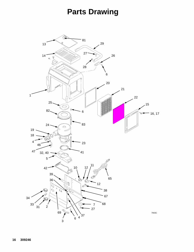
Parts Drawing
31
29
28
20
33 7
3
27
5
38
16, 17
42
25
24
2627
36
34
2
1
41
6
6
23
1210
13
14
15
81
19
18
21
22
32, 40
46
47
37
3965
67
68
69
4
6 4
83
82
7943C
12
11

309246 17
Parts ListRef No. Part No. Description Qty
Ref No. Part No. Description Qty
1 276674 COVER, turbine 12 197111 BASE PLATE, turbine
(System 2500�) 1192775 BASE PLATE, turbine
(System 3800�) 1192774 BASE PLATE, turbine
(System 4900�) 13 192786 PLATE, retaining (System 3800�
and System 4900�) 14 114669 SCREW, pan hd 45 192787 DUCT, turbine 16 114670 SCREW, cap, hx hd 87 113817 BUMPER 410 114064 PLUG, inlet 111 114065 PLUG, inlet, female (System 3800�
and System 4900�) 112 114410 SCREW, pan hd, torx 613 244166 LID, tool box 114 197054 FOAM PAD, tool box 115 197057 RETAINER, filter 116 192895 SCREW, captive 417 158486 O-RING 418 193057 FITTING, outlet (System 2500�) 1
192779 FITTING, outlet (System 3800�and System 4900�) 1
19 156698 O-RING, buna–n 120 192789 GASKET, filter (System 3800�
and System 4900�) 221 240273 FILTER, main, paper (System
3800� and System 4900�) 1244137 FILTER, main, foam (System
2500�) 122† 240274 FILTER, pre 123 193068 SPACER, turbine (System 2500�) 3
192780 SPACER, turbine (System 3800� and System 4900�) 3
24* 240269 TURBINE KIT, 2 stage; 120 volts(System 2500�) 1
240270 TURBINE KIT, 3 stage; 120 volts(System 3800�) 1
241122 TURBINE KIT, 4 stage; 120 volts(System 4900�) 1
25 192812 GASKET, turbine (System 2500�) 1192788 GASKET, turbine (System
3800� and System 4900�) 126 192784 BRACKET, handle 227 114531 SCREW, cap, hx hd 828 113414 NUT, lock 229 192785 HANDLE, turbine 131 114658 SWITCH, rocker (System 4900�) 1
32 114279 SENSOR, pressure (System 3800� and System 4900�) 1
33 114280 LIGHT, indicator (System 3800� and System 4900�) 1
34 114293 SWITCH, rocker, red 136 111593 SCREW, grounding 137 102063 WASHER, lock, external tooth 138 114290 BREAKER, circuit; 8A, 120V
(System 2500�) 1114403 BREAKER, circuit; 15A, 120V
(System 3800� andSystem 4900�) 1
39 192905 PLATE, deflector (System3800� and System 4900�) 1
40 193059 GASKET, sensor (System3800� and System 4900�) 1
41 192845 GASKET, duct 142 192846 GASKET, duct 146 114287 FITTING, barbed (System
3800� and System 4900�) 147 192810 HOSE, air (System
3800� and System 4900�) 165 245202 CORD SET, 10 ft, 13A, 120V
(System 2500� & System 3800�) 1240281 CORD SET, 15 ft, 15A, 120V
(System 4900�) 167� 193095 LABEL, danger 168� 193096 LABEL, warning 169 193126 LABEL, caution 175 244122 #2/4/5/6 ACCESSORY KIT
(System 4900�) Not shown 181 114538 SCREW, mach, pan hd 282 194094 PLATE, turbine 183 SPACER, turbine
194095 System 2500� 3194096 System 3800� 3194097 System 4900� 3
† Pre-filters are available in 5 packs. Order Part No.240274.
* Turbine Brush Kits are also available. Purchaseseparately: 240545 (for System 2500�),
and 240546 (for System 3800� and System4900�).
� Extra danger and warning labels are availablefor free.

18 309246
Accessories21/2-Gallon (9.5 liter) PTFE� coated Pot 240045
50 psi (345 kPa, 3.5 bar) Maximum Inlet Air Pressure
21/2-gallon (9.5 liter) capacity, steel tank. Includes airpressure regulator, gauge, and pressure relief valve.
04957
217
202
208
209
212
203
207
212
204205
216
201 221
21/2-gal (9.5 liter)paint tank liner(5 pack) 112077
Ref. No. Part No. Description Qty.201 104655 PRESSURE GAUGE 1202 151519 REDUCER, 1/4 to 1/8 1203 M70687 COUPLING 1204 M70676 O-RING 1205 M70686 PRESSURE RELIEF VALVE 1207 M70616 GASKET, standard; EPDM 1
M70617 GASKET, solvent resistant; Thiokol (optional — must order separately) 1
208 M70678 WING NUT 5209 M70677 WASHER 5212 244288 TANK, paint, 21/2-gal (9.5 liter),
with PTFE� coat 1216 169969 QUICK DISCONNECT, male 1217 104815 PRESSURE REGULATOR 1221 M71639 HANDLE 1

309246 19
Accessories
8483A
Pot Length (ft) Number
21/2gal 2 240074
2 qt 30 240071
Compressor Air Hose
Tie Wrap Kit(10 pack)
103473
Length (ft) Number
30 241423
Air & Material Hose
FS Number
244115
3 244118
Fluid Set (FS)/Spray Gun
None
Length (ft) Number
30 240476
Material Hose
PTFE Lined 240045
Pressure Pot
Length (ft) Number
Standard Turbine Air Hose
30 241413
� See HVLP Fine Finish Systemsbrochure 300564 for all accessories.
� Non-Silicone Lubricant 111265 (4 oz) isavailable for fluid seals and wear areas.
Notes:
20 309246
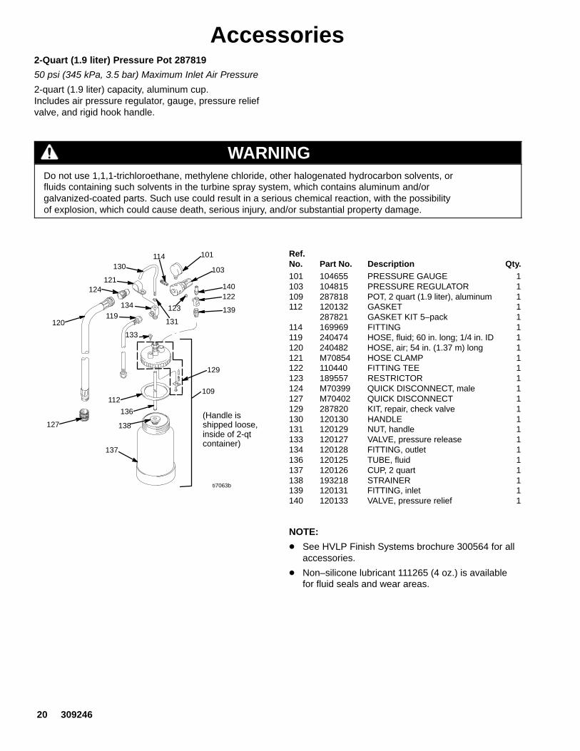
Accessories2-Quart (1.9 liter) Pressure Pot 287819
50 psi (345 kPa, 3.5 bar) Maximum Inlet Air Pressure
2-quart (1.9 liter) capacity, aluminum cup.Includes air pressure regulator, gauge, pressure reliefvalve, and rigid hook handle.
WARNINGDo not use 1,1,1-trichloroethane, methylene chloride, other halogenated hydrocarbon solvents, orfluids containing such solvents in the turbine spray system, which contains aluminum and/orgalvanized-coated parts. Such use could result in a serious chemical reaction, with the possibilityof explosion, which could cause death, serious injury, and/or substantial property damage.
ti7063b
(Handle isshipped loose,inside of 2-qtcontainer)
133
101114130
121124
120
127
112
136
138
137
109
129
119134
131
123
122
139
103
140
Ref.No. Part No. Description Qty.101 104655 PRESSURE GAUGE 1103 104815 PRESSURE REGULATOR 1109 287818 POT, 2 quart (1.9 liter), aluminum 1112 120132 GASKET 1
287821 GASKET KIT 5–pack 1114 169969 FITTING 1119 240474 HOSE, fluid; 60 in. long; 1/4 in. ID 1120 240482 HOSE, air; 54 in. (1.37 m) long 1121 M70854 HOSE CLAMP 1122 110440 FITTING TEE 1123 189557 RESTRICTOR 1124 M70399 QUICK DISCONNECT, male 1127 M70402 QUICK DISCONNECT 1129 287820 KIT, repair, check valve 1130 120130 HANDLE 1131 120129 NUT, handle 1133 120127 VALVE, pressure release 1134 120128 FITTING, outlet 1136 120125 TUBE, fluid 1137 120126 CUP, 2 quart 1138 193218 STRAINER 1139 120131 FITTING, inlet 1140 120133 VALVE, pressure relief 1
NOTE:
� See HVLP Finish Systems brochure 300564 for allaccessories.
� Non–silicone lubricant 111265 (4 oz.) is availablefor fluid seals and wear areas.

309246 21
AccessoriesLubricant
One, 4–ounce (113 gram) tube sanitary (non–silicone)lubricant for fluid seals and wear areas.
1–Quart Under–Cup Assembly 244130
Complete 1–quart under–cup assembly.
1–Quart Cup and Lid 244131
1–quart under–cup with lid for air–tight storage of fluid.
1–Quart Cup 244132
1–quart under–cup.
1–Quart Cup Gaskets 240265
5–pack of polyethylene gaskets for use with 1–quartunder–cup.
Fluid Strainer (3 each) 240267
Install on the end of the cup to strain the fluid and helpeliminate surface blemishes and plugged tips. 100mesh screen.
User Kit #2 and #4 244122
Contains #2 and #
Y Fitting Kit 240069
Creates two air connections; allows for two–gunoperation.
SpecificationsPower requirements 120V AC, 50/60 Hz. . . . . . . . . . . . . . . . . . . . . . . . . . . . . . . . . . . . . . . . . . . . . . . . . . . . . . . . . . . . . . . . . Amps at 120 volts
System 2500� 1 phase, 7A minimum. . . . . . . . . . . . . . . . . . . . . . . . . . . . . . . . . . . . . . . . . . . . . . . . . . . . . . . . . . . . . . . . . System 3800� 1 phase, 12A minimum. . . . . . . . . . . . . . . . . . . . . . . . . . . . . . . . . . . . . . . . . . . . . . . . . . . . . . . . . . . . . . . . System 4900� 1 phase, 14A minimum. . . . . . . . . . . . . . . . . . . . . . . . . . . . . . . . . . . . . . . . . . . . . . . . . . . . . . . . . . . . . . . .
Power cord (extension cord must be 3-wire, 12 AWG, 50 ft [15 m] or shorter)System 2500� No. 16 AWG, 3 wire, 10 ft. . . . . . . . . . . . . . . . . . . . . . . . . . . . . . . . . . . . . . . . . . . . . . . . . . . . . . . . . . . . . . System 3800� No. 16 AWG, 3 wire, 10 ft. . . . . . . . . . . . . . . . . . . . . . . . . . . . . . . . . . . . . . . . . . . . . . . . . . . . . . . . . . . . . . System 4900� No. 14 AWG, 3 wire, 15 ft. . . . . . . . . . . . . . . . . . . . . . . . . . . . . . . . . . . . . . . . . . . . . . . . . . . . . . . . . . . . . .
Unrestricted flow rateSystem 2500� 58 cfm. . . . . . . . . . . . . . . . . . . . . . . . . . . . . . . . . . . . . . . . . . . . . . . . . . . . . . . . . . . . . . . . . . . . . . . . . . . . . . System 3800� 80 cfm. . . . . . . . . . . . . . . . . . . . . . . . . . . . . . . . . . . . . . . . . . . . . . . . . . . . . . . . . . . . . . . . . . . . . . . . . . . . . . System 4900� 82 cfm. . . . . . . . . . . . . . . . . . . . . . . . . . . . . . . . . . . . . . . . . . . . . . . . . . . . . . . . . . . . . . . . . . . . . . . . . . . . . .
Turbine stagesSystem 2500� 2. . . . . . . . . . . . . . . . . . . . . . . . . . . . . . . . . . . . . . . . . . . . . . . . . . . . . . . . . . . . . . . . . . . . . . . . . . . . . . . . . . . System 3800� 3. . . . . . . . . . . . . . . . . . . . . . . . . . . . . . . . . . . . . . . . . . . . . . . . . . . . . . . . . . . . . . . . . . . . . . . . . . . . . . . . . . . System 4900� 4. . . . . . . . . . . . . . . . . . . . . . . . . . . . . . . . . . . . . . . . . . . . . . . . . . . . . . . . . . . . . . . . . . . . . . . . . . . . . . . . . . .
Maximum turbine hose lengthSystem 2500� 40 ft (12 m). . . . . . . . . . . . . . . . . . . . . . . . . . . . . . . . . . . . . . . . . . . . . . . . . . . . . . . . . . . . . . . . . . . . . . . . . . System 3800� 60 ft (18 m). . . . . . . . . . . . . . . . . . . . . . . . . . . . . . . . . . . . . . . . . . . . . . . . . . . . . . . . . . . . . . . . . . . . . . . . . . System 4900� 60 ft (18 m). . . . . . . . . . . . . . . . . . . . . . . . . . . . . . . . . . . . . . . . . . . . . . . . . . . . . . . . . . . . . . . . . . . . . . . . . .
Cup volume 1 quart (0.95 liter). . . . . . . . . . . . . . . . . . . . . . . . . . . . . . . . . . . . . . . . . . . . . . . . . . . . . . . . . . . . . . . . . . . . . . . . . . Wetted parts
Bare spray gun stainless steel, brass, PTFE, hard-coated aluminum. . . . . . . . . . . . . . . . . . . . . . . . . . . . . . . . . . . . . . . Spray gun cup aluminum, polyethylene. . . . . . . . . . . . . . . . . . . . . . . . . . . . . . . . . . . . . . . . . . . . . . . . . . . . . . . . . . . . . . . . 2-quart (1.9 liter) accessory remote pressure pot aluminum, brass, polyethylene. . . . . . . . . . . . . . . . . . . . . . . . . . . . 21/2-gallon (9.5 liter) accessory remote pressure pot steel with solvent-resistant finish,. . . . . . . . . . . . . . . . . . . . . . .
EPDM gasket (standard)Turbine shipping weight
System 2500� 32 lb (14.5 kg). . . . . . . . . . . . . . . . . . . . . . . . . . . . . . . . . . . . . . . . . . . . . . . . . . . . . . . . . . . . . . . . . . . . . . . . System 3800� 34 lb (15.4 kg). . . . . . . . . . . . . . . . . . . . . . . . . . . . . . . . . . . . . . . . . . . . . . . . . . . . . . . . . . . . . . . . . . . . . . . . System 4900� 36 lb (17.7 kg). . . . . . . . . . . . . . . . . . . . . . . . . . . . . . . . . . . . . . . . . . . . . . . . . . . . . . . . . . . . . . . . . . . . . . . .
Turbine diameter 5.7 in (144.78 mm). . . . . . . . . . . . . . . . . . . . . . . . . . . . . . . . . . . . . . . . . . . . . . . . . . . . . . . . . . . . . . . . . . . . . Sound level per ISO 3744
Sound power level 89.0 dB(A). . . . . . . . . . . . . . . . . . . . . . . . . . . . . . . . . . . . . . . . . . . . . . . . . . . . . . . . . . . . . . . . . . . . . . . . . Sound pressure level 78.0 dB(A). . . . . . . . . . . . . . . . . . . . . . . . . . . . . . . . . . . . . . . . . . . . . . . . . . . . . . . . . . . . . . . . . . . . . .

22 309246
Graco Standard WarrantyGraco warrants all equipment referenced in this document which is manufactured by Graco and bearing its name to be free fromdefects in material and workmanship on the date of sale to the original purchaser for use. With the exception of any special, extended,or limited warranty published by Graco, Graco will, for a period of twelve months from the date of sale, repair or replace any part of theequipment determined by Graco to be defective. This warranty applies only when the equipment is installed, operated and maintainedin accordance with Graco’s written recommendations.
This warranty does not cover, and Graco shall not be liable for general wear and tear, or any malfunction, damage or wear caused byfaulty installation, misapplication, abrasion, corrosion, inadequate or improper maintenance, negligence, accident, tampering, orsubstitution of non-Graco component parts. Nor shall Graco be liable for malfunction, damage or wear caused by the incompatibility ofGraco equipment with structures, accessories, equipment or materials not supplied by Graco, or the improper design, manufacture,installation, operation or maintenance of structures, accessories, equipment or materials not supplied by Graco.
This warranty is conditioned upon the prepaid return of the equipment claimed to be defective to an authorized Graco distributor forverification of the claimed defect. If the claimed defect is verified, Graco will repair or replace free of charge any defective parts. Theequipment will be returned to the original purchaser transportation prepaid. If inspection of the equipment does not disclose any defectin material or workmanship, repairs will be made at a reasonable charge, which charges may include the costs of parts, labor, andtransportation.
THIS WARRANTY IS EXCLUSIVE, AND IS IN LIEU OF ANY OTHER WARRANTIES, EXPRESS OR IMPLIED, INCLUDING BUTNOT LIMITED TO WARRANTY OF MERCHANTABILITY OR WARRANTY OF FITNESS FOR A PARTICULAR PURPOSE.
Graco’s sole obligation and buyer’s sole remedy for any breach of warranty shall be as set forth above. The buyer agrees that no otherremedy (including, but not limited to, incidental or consequential damages for lost profits, lost sales, injury to person or property, or anyother incidental or consequential loss) shall be available. Any action for breach of warranty must be brought within two (2) years of thedate of sale.
GRACO MAKES NO WARRANTY, AND DISCLAIMS ALL IMPLIED WARRANTIES OF MERCHANTABILITY AND FITNESS FORA PARTICULAR PURPOSE, IN CONNECTION WITH ACCESSORIES, EQUIPMENT, MATERIALS OR COMPONENTS SOLDBUT NOT MANUFACTURED BY GRACO. These items sold, but not manufactured by Graco (such as electric motors, switches,hose, etc.), are subject to the warranty, if any, of their manufacturer. Graco will provide purchaser with reasonable assistance inmaking any claim for breach of these warranties.
In no event will Graco be liable for indirect, incidental, special or consequential damages resulting from Graco supplying equipmenthereunder, or the furnishing, performance, or use of any products or other goods sold hereto, whether due to a breach of contract,breach of warranty, the negligence of Graco, or otherwise.
FOR GRACO CANADA CUSTOMERSThe parties acknowledge that they have required that the present document, as well as all documents, notices and legal proceedingsentered into, given or instituted pursuant hereto or relating directly or indirectly hereto, be drawn up in English. Les partiesreconnaissent avoir convenu que la rédaction du présente document sera en Anglais, ainsi que tous documents, avis et procéduresjudiciaires exécutés, donnés ou intentés à la suite de ou en rapport, directement ou indirectement, avec les procedures concernées.
ADDITIONAL WARRANTY COVERAGEGraco does provide extended warranty and wear warranty for products described in the “Graco Contractor Equipment WarrantyProgram”.
Phone NumberTO PLACE AN ORDER, contact your Graco distributor, or call this number to identify the distributor closest to you:
1–800–690–2894 Toll Free
All written and visual data contained in this document reflect the latest product information available at the time of publication.Graco reserves the right to make changes at any time without notice.
mm 309246This manual contains English
Graco Headquarters: MinneapolisInternational Offices: Belgium, Korea, China, Japan
GRACO INC. P.O. BOX 1441 MINNEAPOLIS, MN 55440–1441www.graco.com11/2000, Rev 8/2006