30hxc 075-370 screw compressor water-cooled …...ouality assurance 30hxc 075-370 screw compressor...
TRANSCRIPT

OUALITY ASSURANCE
30HXC 075-370Screw CompressorWater-Cooled ChillersNominal cooling capacity 259- 1296 kW
GIOBAT CHITIER
The 30HXC units are water-cooled chillers designed fromthe ground up to meet the needs of today and tomorrow,including:- chlorine-free HFC- I 34a refrigerant,- smooth compression using screw compressors,- fits through a standard door with no disassembly required,- mechanically cleanable coolers and condensers.
FeaturesQuality design and construction make'the 30HXC unit thepreferred choice.
r Use of ozone-benign HFC-134a refrigerant which has noplanned phase-out. HFC-134a is a proven non-toxic. non-flammable refrigerant which will have the highest usage ofany new refrigerant.
I The 30HXC units have a quiet, low-vibration design featur-ing screw compressors.
Efficiency levels of the 30HXC units exceed average indus-try standards, fbr both fïll- and part-load operation, thussaving. on operating costs, through lower elèctrical con-sumptlon.The 30HXC controls are tully auromaric. The leaving fluidtemperature is directly controlled, and the entering fluidtemp€rature is continuously monitored to detect load andflow changes. This combination provides the most precisetemperature control available.Dual, independant refrigerant circuiqs provide reliable,dependable cooling, and the 30HXC units use medium-' pressure HFC-134a refrigerant to minimize stress on thecompressors and ensure long life.
4t5

Easv installationi- Ítt. 30HXC has a compact design that fits through a stand-
ard door opening and requires minimal indoor sp-ace'The 30HXC is ci-elivered as a complete package for easyinstallation. There are no extra controls, timers, starters, or
other items to install.r 30HXC units have a single power point and one disconnect
switch (option) for sizei075-185, ànd one powe^r point andone main-disconnect switch per circuit (option) for sizes2r5-370.The hydraulic connections are simple and facilitated by theose offlanges for the condenser and evaporator.
I The 30HXÓ units are designed to ensure maximum compli-ance with European standard EN 60204.
r Quick start-up is assured once installation is complete, asàh:OHXC unit is manufactured at an ISO 9001-listedmanufacturing facility to guarantee Qlality. In addition' allunits are testet undeifull load at the factory to providereliable start-uP.
Controlsr The units are equipped with intelligent PIC micropro-cessor
controls which êon[inually monitor and optimize chillerefficiency in line with operating condition changes..The basió PIC controls consist of a processor module(PSIO-2), VO boards, an EXV driver, a keypad ard displaymodule (HSIO II), and a dedicated microprocessor com-pressor Protection board (CPM)The capàcity control algorithm control,s the electronicexoansion valve, compressors and loaders, to maintain theleáving water setpoint.
r There-are six major functions: STATUS, HISTORY'SCHEDULE, SERVICE, SETPOINT ANdTEST, AII Ofwhich have a variety of subfunctions accessed via theHSIO II or remotelY'Features include:- Diagnostic capabilities/service history- Variable water flow caPabilitY- LOCAL or REMOTE interface- BMSiCCN compatible- Optional enhanced interface
t Dedicated microprocessor comPressor protection boardsprovide:- Protection and monitoring features- Control and output features- Diagnostic communication ability via the PSIO, for
example of comPressor alarms.t Protection and monitoring features include:
- Locked rotor and overcurrenl protection- No current detection- Reverse rotation protection- Ground fault and unbalanced voltage detection- Unbalanced current- Phase loss voltage Protection- Phase loss current Protection- Winding temperature safety device- High pressure switch
- Comoressor contactor failure.l The control cabinets are designed and fully tested to meet
EUROPEAN COMMUNITY DIRECTIVES, (CE marked)for:- Electromagnetic comPatibilitY- Low voltage equiPmentServiceability and convenience have been "designed-in",for example:- Control transformer is fitted as standard- Single-point mains power connectlon- All components are mounted using connectors to facili-
tate fast servicing and replacement '
- Components are indelibly labelled and numbered accord-ing to wiring diagrams
- Afi components are mounted on an orange backplateiboard to distinguish them and to avoid mounting on therear of the control box.
- HSIO II user interface accessible through a dedicatedaccess door
- Door interlock isolator as an option.
Simple to serviceI Mechanically cleanable cooler and condenser'r Twin-screw compressors which require minimum routine
service or maintenance.I Easily accessed suction and discharge pressure and tem-
perature information using enhanced display module.
OptionsI Star delta start.I Main disconnect switch.I 21 bar maximum cooler operating pressure water side.I 21 bar maximum condenser operating pressure water side.I Cooler and condenser water pump control pack.I Remote control module:
- electrical demand iimit control (4-20 mA signal)- evaporator setpoint reset (4-20 mA signal)- condenser water valve control (4-20 mA signal).
r IP54 protectibn.t Fewer evaporator Passes.r One-pass condenser.
416
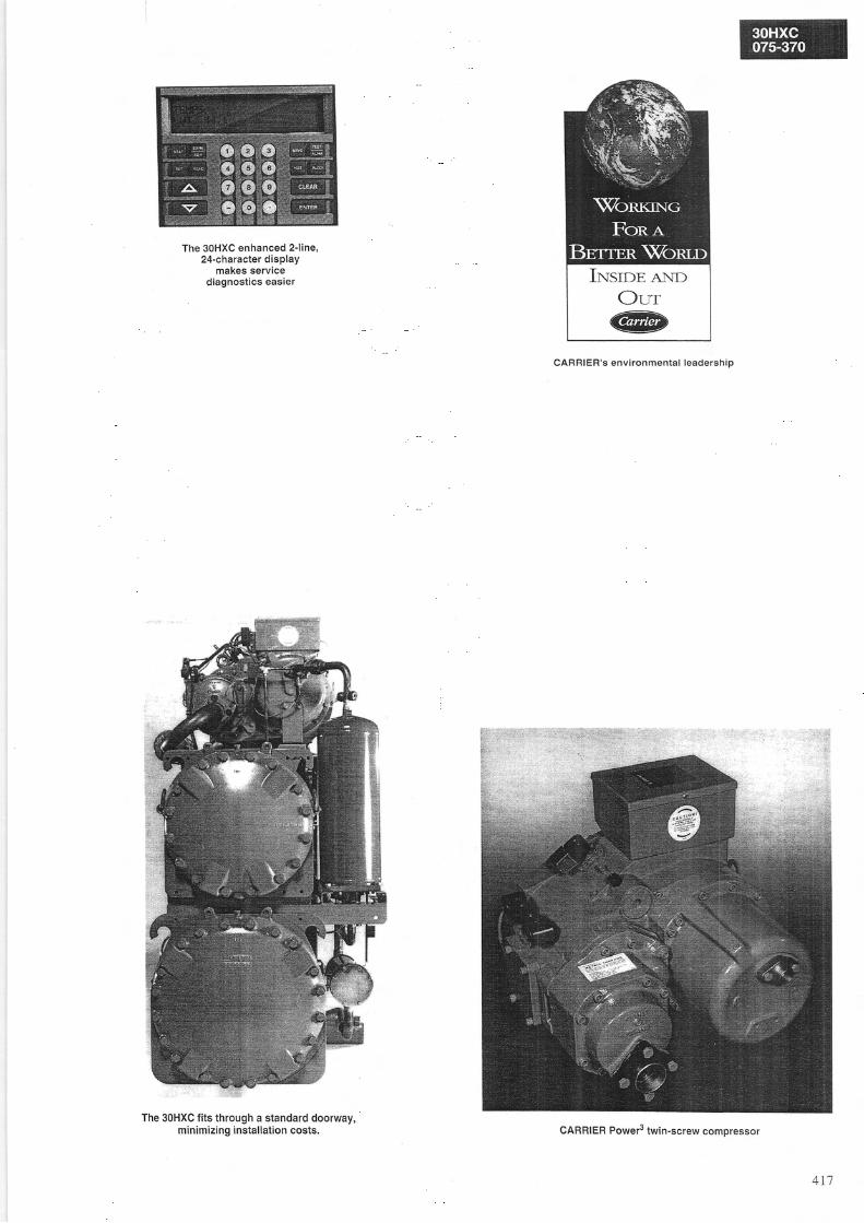
The 30HXC enhanced 2-line,24-character display
makes servicediagnostics easieÍ
The 30HXC Íits through a standard doorway,minimizing installation costs.
CARRIEB's env i ronmenta l leadersh ip
Irqsrr>e ANDOrr
CARRIER Power3 twin-screw comoressor
417

Physical data30HXC o75 oa5 o95 105 1 1 5 125 t35 145 t60 1 7 0 185
Gross nominal coolingcapacity.
KW 258.9 308.0 339.6 376.4 412.5 443.4 484.9 537.0 576.9 584.3 643.5
Operating weight kg 2503 251 I 2560 1 í O l 2833 2872 zvJo 2971 3283 3403 351 7
Refrigerani HFC-1 34a
t 5 51421391261171 0 49690787B63Total rêtrigerant charEê kq
CompressorQuantity, circuit AQuantity, circuit BEconomizeÍNumber of capacity stepsMinimum capacity
Semr-hermetic twin screw1 1 1 1
1No620
I
1No620
11No
20
1No620
1No620
'I
No620
11No620
'1
1No620
11No620
1 11 1Yes Yes6 620 20
CoolerNet water volumeNumber oÍ refrigeÍant circuitsWater conneclionslnlêt & outlet diameterAir venl diameter(on wateÍ box)Water drain diametêÍ(on water box)Maximum operating pressurewater side
One shell & tube cooler with enhanoed copper tubeso c a c / ó
2 2 287 812 2
'1 000 1 000 1000 1000
81 912 2
5 5
3/8'NPT 3I8" NPï
3/8'NPT 3/8" NPT
1000 1000
9 1
5
3/8" NPT
3/8" NPT
1 000
1 0 92
1092 2
6
3/8" NPT
3/8" NPT
1 000
Factory supplied flat Ílange to be site welded4 4 4 5 5
3/8 'NPT 3/8" NPT 3/8" NPT 3/8 'NPT 3/8 'NPT
3/8" NPT 3/8" NPT 3i8" NPT 3/8" NPT 3/8" NPT
3 5
3/8" NPT 3/8" NPT
3/8" NPT 3i8" NPT
1000 1000kPa 1000
CondenserNet water volumeNumbeÍ oÍ ÍeÍrigerant circujtsWater connectionsInlet & outlel diameterAir vent diameter(on wateÍ box)Water drain diameter(on wateÍ box)lvlaximum opeíating pressurewater side
One shell & tube condenser with enhanced copper tubes67 67 67 742 2 2 2Factory supplied Ílat Ílange to be site weldeds 5 5 5
3/8" NPT 3/8'NPT 3i8" NPï 3i8" NPT
3/8" NPT 3i8" NPT 3/8" NPT 3/8" NPT
89 962 2
5 5
3/8" NPT 3i8" NPT
3/8" NPT 3/8" NPT
1000 1000
5 5
3/8" NPT 3/8" NPT
3/8" NPT 3/8" NPT
1000 1000
132 136 1452 ) )
0 0 b
3/8" NPT 3/8" NPT 3i8'NPT
3/8" NPT 3/8" NPï 3/8" NPT
1000 1000 1000
1 1 02
1 1 02
kPa 1000 1000 1000 1000
30HXC 2.t5 250 3 Í 5 340 37(}
Gross nominal cooling capacity' KW 851 .0 9 1 1 . 3 962.7 1022.6 1 183 .1 1295 .9
Operating weight kg 4730 4996 5021 5046 5890 6070 6 1 1 5 61 65
ReÍrigerant HFC-1 34a
Total reÍrigerant charge l(g I / O 200 224 272
CompressorQuantity, circuii AQuantity, circuit BEconomizerNumber oÍ capacity stepsMinimum capacity
Semi-hermetic twin screw2 21 1No Yes8 8t 9 t c
21Yes8I J
21Yes8
22Yes1 01 0
22Yes1 0'í0
22Yes1 01 0
22Yes1 01 0
CoolerNet water volumeNumber of reÍigerant circuitsWater connectionslnlet & outlet diameterAir vent diameter (on water box)Water drain diameter (on water box)Maximum operating pressure water side
One shell & tube cooler with enhanced cooper tubes1 6 5 1 8 12 2
203 229 229)
I3/8" NPT3/8" NPT1 000
2292
I3/8" NPT3/8" NPT1 000
1 8 12
1 8 12
kPa
Factory supplied flat flange to be site welded6 6 6 6 8 83/8" NPT 3/8" NPï 3/8" NPT 3/8" NPT 3/8" NPT 3/8" NPT3/8" NPï 3/8'NPT 3/8'NPT 3/8" NPT 3/8" NPT 3I8" NPT1000 1000 1000 . t000
1000 1000
CondenserNet water volumeNumber oÍ ÍeÍrigerant circuitsWater connectionslnlet & outlet diameterAir vent diameter (on water box)Water drain diameter (on water box)Maximum operating pressure water side
One shell & tube condenser with enhanced coooer tubes208 2082 2 2 2Factory supplied flat flange to be site welded6 6 6 63/8" NPT 3/8'NPT 3/8" NPT 3/8" NPT3/8" NPT 3i8" NPT 3/8" NPT 3i8" NPT
kPa 1000 1 000 1 000 '1000
208208 z ó l
22512
2512
8
3/8" NPï
3 / 8 ' N P T
1 000
z c l
2
I3/8" NPT3/8" NPT1 000
ó U3/8" NPT 3/8" NPT3/8'NPT 3/8" NPT1000 1000
Legend:' Eurovent conditions:
EvaPoÍator enteÍing/leaving water temperature 12'C and 7"C, condenser entering/leaving water temperature 30.C and 35"C
4 1 8

Electrical data075 oa5 095 í05 l í 5 125 í35 145 160 170 1 8 530HXC
Mains power suPP|YNominal voltageVoltage range
V-ph-Hz 400-3-50o/. + 10
Control circuit voltage*
Nominal power inPutNominal operating current**Maximum operating current*"'Maximum starting currentAcross the line start.'..Opiional star-delt
V-ph-Hz 230-1-50
kw 56.5 63.5A 36.5 108.0A 142 157A
415 494180 205
70.7 79.5 85.0120.2 134.8 143.9175 19s 210
577 676 691231 262 277
93.0 103.1 117 ,7154.0 171 .3 195.2228 255 275
709 819 839295 330 350
125.3 124,3 135 B207.1 206.0 225.4302 300 330
866 992 1021377 406 435
30HXC 215 250 265 2AO 30(' 3 1 s 340
Mains power suPPlYNominal voltageVoltage rangê
V-ph-Hz 400-3-50y . t 1 0
Control circuit voltage-Nominal power inputNominal operating current**Maximum operating current**.Circuit Aurrcutl È,Maximum starting currentAcross the line start****Optional star-delta start*'".
V-ph-Hz 230-1-50kw 168.1A 281 .2
255t c l
970481
182.0298.0
278165
1 134548
192.0320.9
300t o c
1 1 5 6570
203.4ea^ À
330t o c
1 186600
208.6351.2
248271
1 0996 1 0
223.0372.1
278274
1247661
224.4499.7
300300
1292706
269.0444.5
330330
1 350764
Legend;Conlrol power circuit is supplied thÍough factory-installed transÍormerCurrent drawn at cooler entering/leaving temperaturê 12'Cn"C, condenser enteÍing/leaving temperature 30"C/35'C and al 400 V nominal voltage
Maximum cuÍÍent drawn by compressoÍs at Íull load and at minimum voltage of 360 VMaximum instantaneous starting current
Electrical dala notes:. 3OHXC 075 to 185 units have a single poweí connection point, units 30HXC 215 lo 370
have two poweÍ connection Points.. The control box incorporates the Íollowing standard Íeaturesr
- Starters Íor each compÍessoÍ- ContÍol devices
. Field connections:All connections to the system and electrical installation must be in Íull accoÍdance with allapplicable European directives.
. The Carrier SOHXC units are designed to ensuÍe conformance with these directives. Therêcommendations oÍ European standard EN 60204-1 (machine safêty - electrical machinecomponents - part 1: general regulations) are sPeciÍically taken into account, when design-ing the electrical equipment.
NOTES:. Generally the recommendations of lÊC 364 are accepted as compliance with these
requirements ol the insÍallation diÍectives. Conformance with EN 60204 is the best meansoÍ ensuring compliancê with the Machines Directive S 1.5.1.
. Annex B oÍ EN 60204-1 describes the electrical characteristics used foÍ the operation oÍthe machines.
1. ïhe opêrating environment Íor 30HXC chil lers is speciÍied below:a. Environment - Environment as classified in IEC 364 S 3:
.ambient tempeÍature range: + 6"C lo + 40"C, class AA4
.humidity range (non condensing)507. relative humidity at 40'C90% relative humidity at 20'C
. alt itude: < 2000 m
.indoor installation'presence oÍ water: class AD2 (possibility of water droplets).Presence oÍ hard solids; class AE2 (no signi'Í icant dust present).Presence oÍ coÍrosive and polluting substances, class AF1 (negligible)' Vibration and shock: class AG2, AH2
b. Competence of personnel: class BA4- (trained personnel - IEC 3il).2. Power supply frequency variation; ! 2 Hz3. The neutral line (N) must not be directly connected to ihe unit (if necessary use a trans-
former)4. OveÍcurrênt protection of the power supply conductors is not provided with the unit.5. The Íactory-installed circuit breaker (iÍ ordered) is oÍ type "a" (EN60204-1 5 5.3.2).
NOTÊ:lÍ Darlicular asoects oÍ an actual installation do not conÍorm to the condilions describedabove, oÍ iÍ there are other conditions which should be considered, always conlact yourlocal CarÍieí representative.
'Therêqu i redpro tec t ion leve l fo r th isc lass is lP2 lB(accord ing tore ie rencedocument
419

Condenser water flow rates
' Based on a velocity oÍ 0.3 r/s in a closed loop, and 0.9 m/s in an open loop.** Based on a water velocity oÍ 3.6 m/s.
Cooler water Ílow rates
Unit operating and start-up range
0 5 1 0 1 5 2 0Cooler leaving wateÍ temperature, .C
Notes:1. Cooler and condenser ̂ T = 5 K2. For start-.up wilh a condenser entering water tempeÍature below 20"C, a 3-way valve
is mandatory to maintain proper condênsing temperature (3-way valve, 4-20 mAconÍol available wilh option 128).
3. Maximum condenser leaving temperature 45"C.
3()HXC Minimum flow rate. l/s*
Closed loop Open loop
Maximumflow rale. l/s**
o7s.og5't05
1 1 5125
Í35'145í6(,170í4521s-280300.370
2.52.93.13.2a e
4.64.95.37.27.9
7 .58.89.3
11,413 .814.916 .02 1 . 523.6
29.9
35.037.238.8
45.655.359.864.086.294.5
Oqt
fro
E0)
6-C
co
o
o!
3OHXC Minimumflow rate. Ys
MaximumÍlow rate, l/s
o75-O85o951('5115-125! 35.1 45I 60.1 70' t85
21525o-2AO300315-370
o . o
6.79 .1Y . C
11.214.116.417 .021.0
26.8
26.227.Q36.237.044.756.365.567.984.088.7
107.2
D i mensionsicl ea rances30HXC 075-185
30HXC07530HXC08530HXC09530HXC1 05
LegendiAll dimensions are an mm
u trvaporaror
ai condenser\ - /A Space required Íor seruice\-_/aÀ Space required for lube removal
@= water intet
@ Water outtet
ÉF> Power suppty
30HXC cBA
NOTE: CertiÍied dimensional drawings available on request.
420
o75-O951051 { 5 . í 4 5í 60-í a5
2730JCJC
3550
17751 82517751 900
1 0001 0001 0001 000
2360236032203220
Ílffiï:"
@

30HXC 215-370
Lêgend:All dimonsions aÍe in mm
u Evaporator
()t condenser\:-/íj) space required for service
O Space required íor tube removal
@ Water inlet
@ WateÍ outlet
U1l> PowersuPPlY
z',t5.240300.370
3995 2015 3620 10004488 2068 4120 1000
NOTE: CeÍtiÍi€d dimensional drawings available on requesl.
42r
Technical descriptionWater-cooled packaged liquid chiller for indoor installa-tion, equipped with numerical control and electronic expan-sion valves, and operating with chlorine-free refrigeraniHFC-134a.
Quality assuranceDesigned and manufactured in a factory accredited toQuality Assurance Standard ISO 9001. Performances inaccordance with EUROVENT recommendations.
ChassisBrazed-steel or bolted chassis, with polyester-powder paintfinish, electrostatically applied and oven baked beforeassembly. Colour dark grey (RAL 7037).
CompressorsSemi-hermetic twin-screw compressors with internalmuffler and check valve,Each compressor is equipped with a discharge shutoffvalve.
CoolerMulti-tube evaporator with 2 independant refrigerantcircuits, internally-enhanced, seamless copper tubes,expanded into tube sheets.Thermal insulation of the shell and end covers usinsl9 mm closed-cell polyurethaneMechanically cleanable shell and tube type with removableheads.
CondensersMulti-tube condenser with 2 independant refrigerant cir-cuits, internally-enhanced, seamless copper tu6es,expanded into tube sheets.Mechanically cleanable shell and tube type with removableheads.
Refrigerant circuitsEach refrigerant circuit includes one or fwo comDressors.oil separator, replaceable core filter drier, combiired mois-ture indicator and sightglass, discharge and liquid shutoffvalves, expansion valve, refrigerant economizer(30HXC 1'10-370 except 30HXC 215).
Control box power and control wirinqGalvanized sheet steel. polyesrer paint fïnish, colour lightgrey (RAL 7035), with hinged access doors, containinf:compressor fuses and contactor, confrol circuit trans_
*
former, 3-phase power supply terminals. Inside of controlbox painted in orange, control circuit cables and electricalcomponents numbered.
Numeric control accessible without opening the con_trol box, offers:I PID control of leaving water temperature with return tem_
perature compensation for controi of compressors.and elec_Lronic expansion valves.
I Protection against abnormal operating conditions, high orlow refrigerant pressure, low suction temperature. iniuffi_cient chil led water f low. compressor reuerse rotation, lowoil pressure, voltage imbalance, ground current, thermaloverload, electrical overload, loss of phase, erc.
I Communication: Unit controls include a2_Iine, 24_charac_ter per line diagnostic display. Display module is capableof dispiaying seipoints, rime, sysrem ótatus (includine tem_peratures, pressures, and percent loading), and any alarmsor alert conditions.Remote control: starístop, dual setpoint, setpoint adjust_ment. demand limit conrr_ol. generai fault reporting.
-
The controls can be interfaced with the Carrier CimfortNetwork (CCN) if desired.
Order_No. 13179-?e, August 1997. Supersedes order No. .13.179.20, April .1997.Manutacturer reserues the r;ght to change any product specifications withour notrce
Manufactured by: Carrier SA, Montuel, FrancePrintêd on Toially Chlorine Free paper
pr;nied in the Nethêrlands
Á 4 1