31 a crystal-controlled fm signal center - hp archive 31 1958 a crystal-controlled fm signal center...
TRANSCRIPT

JAN 31 1958 , I /
A Crystal-Controlled FM Signal Center CHARLES G. GORSS, Development Engilzeer
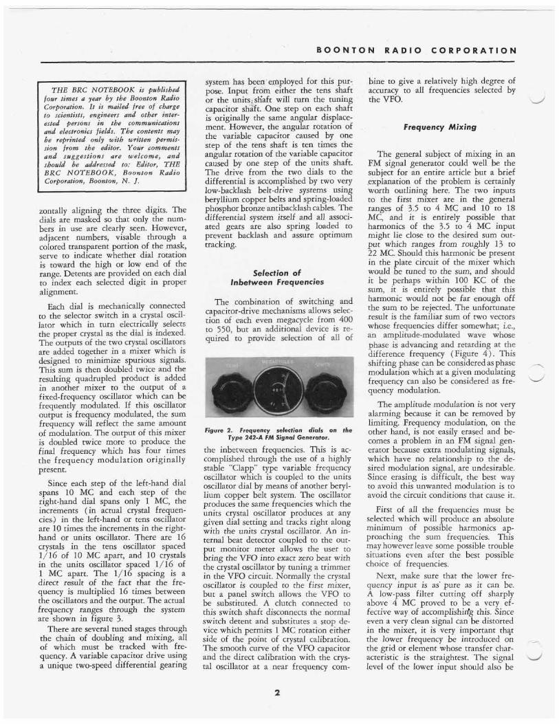
Figure 1. models of the TYPE 242-A FM Signal Generators.
The author i s shown final checking the RF tuning unit on o n e of the first production
A New Concept
As communications systems get more precise and complicated, the demands placed upon the design of equipment required to test and calibrate these sys- tems become more severe. One soon finds that the old standby signal gen- erator no longer will do the job. Old concepts of high-frequency accuracy and stability are inadequate in systems crammed one next to the other, where
YOU VVlLL FIND . . . The RX Meter or the Q Meter? . . . . . . . 5
Use of Markers on Sweep Signal Generator Type 240-A . .. .. . . .... . 7
Editor's ,Note . . . . . . . . . . . . . . . . . . . . . . 8
each channel carries several subcarriers, and each subcarrier in turn carries its own information. In addition, with tech- nical pursuits being carried on from pole to pole; in the arctic cold, the desert heat, the destructive humidity of the jungle, and the thin air of the higher altitudes; the signal generator must now be de- signed to perform in environments strangely different than the cozy labora- tory or factory. The signal generator de- scribed in this article employs design techniques which meet the challenge of these stringent modern requirements.
Design Considerations
First of all, the signal generator under consideration must be crystal controlled or stabilized with an accuracy in the .order of 0.002 per cent. This is a typical long-term accuracy figure for a crystal
oscillator. Since many changes of fre- quency may be required in the set up of multichannel systems, the test frequen- cies must be selected quickly and easily. Even though frequency control by crys- tals implies a finite number of channels, provision must be made for easy selec- tion of between-channel frequencies for bandwidth determination and for the selection of off-beat frequencies. Fre- quencies so selected should also be rea- sonably accurate and stable. The gen- erator should be frequency modulated and feature a wide deviation range (in the order of 300 KC) with little distor- tion. In addition, an optional compressor should be provided so that large changes in input modulation, caused by adding several subcarriers at one time, does not result in over modulation. The com- pressor should not increase distortion appreciably. Besides handling a wide range of external modulating frequen- cies, the generator should provide at least two different internal modulation frequencies, so that simple tests can be performed with no extra input equip- ment. Last but by no means least, the instrument must be rugged in design and must be able to survive not only wherever man can survive, but a few places where he cannot survive for long.
Design Techniques
Selection of I MC Frequencies A frequency selection system employ-
ing two I dials (Figure 2 ) was chosen to cover the range of frequencies from 400 to 550 MC in one megacycle steps. The dials are mounted side-by-side near- ly touching each other. The first two digits are on the left-hand dial and range from 40 to 5 5 in 16 steps. The right-hand dial carries the last digit ranging from 0 to 9 in 10 steps. Every whole number from 400 to 550 can be selected by rotating both dials and hori-
B O O N T O N R A D I O C O R P O R A T I O N
THE BRC NOTEBOOK is published four times a year by the Boonton Radio Corporation. I t is mailed free of charge to scientists, engineers and other inter- ested persons in the communications m d electronics fields. The contents may &e reprinted only with written permis- sion from the editor. Your comments and suggestions are welcome, and should be addressed to: Editor, THE BRC NOTEBOOK, Boonton Radio Corporation, Boonton, N . J.
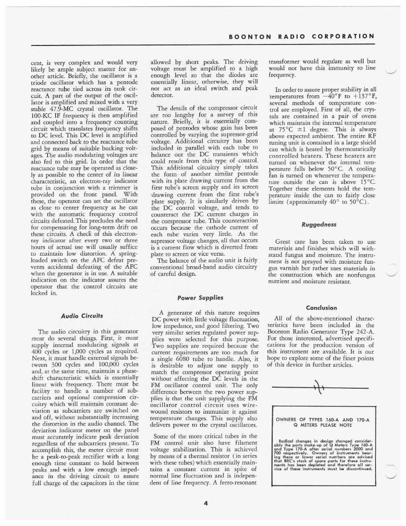
zontally aligning the three digits. The dials are masked so that only the num- bers in use are clearly seen. However, adjacent numbers, visable through a colored transparent portion of the mask, serve to indicate whether dial rotation is toward the high or low end of the range. Detents are provided on each dial to index each selected digit in proper alignment.
Each dial is mechanically connected to the selector switch in a crystal oscil- lator which in turn electrically selects the proper crystal as the dial is indexed. The outputs of the two crystal oscillators are added together in a mixer which is designed to minimize spurious signals. This sum is then doubled twice and the resulting quadrupled product is added in another mixer to the output of a fixed-frequency oscillator which can be frequently modulated. If this oscillator output is frequency modulated, the sum frequency will reflect the same amount of modulation. The output of this mixer is doubled twice more to produce the final frequency which has four times the frequency modulation originally present.
Since each step of the left-hand dial spans 10 MC and each step of the right-hand dial spans only 1 MC, the increments (in actual crystal frequen- cies.) in the left-hand or tens oscillator are 10 times the increments in the right- hand or units oscillator. There are 16 crystals in the tens oscillator spaced 1/16 of 10 MC apart, and 10 crystals in the units oscillator spaced 1/16 of 1 MC apart. The 1/16 spacing is a direct result of the fact that the fre- quency is multiplied 16 times between the oscillators and the output. The actual frequency ranges through the system are shown in figure 3.
There are several tuned stages through the chain of doubling and mixing, all of which must be tracked with fre- quency. A variable capacitor drive using a unique two-speed differential gearing
system has been efiployed for this pur: pose. Input frdm either the tens shaft or the units;skiaft will turn the tuning capacitor shgft. One step on each shaft is originally the same angular displace- ment. However, the angular rotation of the variable capacitor caused by one step of the tens shaft is ten times the angular rotation of the variable capacitor caused by one step of the units shaft. The drive from the two dials to the differential is accomplished by two very low-backlash belt-drive systems using beryllium copper belts and spring-loaded phosphor bronze antibacklash cables. The differential system itself and all associ- ated gears are also spring loaded to prevent backlash and assure optimum tracking.
Selection of lnbetween Frequencies
The combination of switching and capacitor-drive mechanisms allows selec- tion of each even megacycle from 400 to 550, but an additional device is re- quired to provide selection of all of
Figure 2. Frequency selection dials on the Type 242-A FM Signal Generator.
the inbetween frequencies. This is ac- complished through the use of a highly stable “Clapp” type variable frequency oscillator which is coupled to the units oscillator dial by means of another beryl- lium copper belt system. The oscillator produces the same frequencies which the units crystal oscillator produces at any given dial setting and tracks right along with the units crystal oscillator. An in- ternal beat detector coupled to the out- put monitor meter allows the user to bring the VFO into exact zero beat with the crystal oscillator by tuning a trimmer in the VFO circuit. Normally the crystal oscillator is coupled to the first mixer, but a panel switch allows the VFO to be substituted. A clutch connected to this switch shaft disconnects the normal switch detent and substitutes a stop de- vice which permits l MC rotation either side of the point of crystal calibration. The smooth curve of the VFO capacitor and the direct calibration with the crys- tal oscillator at a near frequency com-
bine to give a relatively high degree of accuracy to all frequencies selected by the VFO. d
Frequency Mixing
The general subject of mixing in an FM signal generator could well be the subject for an entire article but a brief ,explanation of the problem is certainly worth outlining here. The two inputs to the first mixer are in the general ranges of 3.5 to 4 MC and 10 to 18 MC, and it is entirely possible that harmonics of the 3.5 to 4 MC input might lie close to the desired sum out- put which ranges from roughly 13 to 22 MC. Should this harmonic be present in the plate circuit of the mixer which would be tuned to the sum, and should it be perhaps within 100 KC of the sum, it is entirely possible that this harmonic would not be far enough off the sum to be rejected. The unfortunate result is the familiar sum of two vectors whose frequencies differ somewhat; i.e., an amplitude-modulated wave whose phase is advancing and retarding at the difference frequency (Figure 4 ) . This shifting phase can be considered as phase modulation which at a given modulating frequency can also be considered as fre- quency modulation.
The amplitude modulation is not very alarming because it can be removed by limiting. Frequency modulation, on the other hand, is not easily erased and be- comes a problem in an FM signal gen- erator because extra modulating signals, which have no relationship to the de- sired modulation signal, are undesirable. Since erasing is difficult, the best way te avoid this unwanted modulation is to avoid the circuit conditions that cause it.
First of all the frequencies must be selected which will produce an absolute minimum of possible harmonics ap- proaching the sum frequencies. This may however leave some possible trouble situations even after the best possible choice of frequencies.
Next, make sure that the lower fre- quency input is as‘ pure as it can be. A low-pass filter cutting off sharply above 4 MC proved to be a very ef- fective way of accomplishirfg this. Since even a very clean signal can be distorted in the mixer, it is very important that the lower frequency be introduced on the grid or element whose transfer char- acteristic is the straightest. The signal level of the Iower input should also be
2

THE N O T E B O O K
kept as low as possible and the element should be so biased that the total swing takes place on the most linear portion of the transfer characteristic. It was found desirable to use a GAS6 tube as a mixer with the 3.5 to 4 MC signal fed into grid number 1 and the higher frequency fed into grid number 3. While this is not the most efficient operation (with only $5 volt on grid number 1) it does greatly reduce the distortion of the signal on grid number 1. Any re- sulting harmonic content can be addi- tionally reduced (if the tuning is accu- rate enough) by tuning the plate of the GAS6 to the sum and following this stage with another sharply tuned stage. In fact, it is necessary to tune these stages for minimum spurious PM in the final set-up procedure.
Carefully following the above prin- ciples results in a minimum of spurious FM. Ignoring these facts would easily result in 100 KC or more spurious FM deviation in the output.
._
Frequency Doubling
The need for doubling to frequencies up to 550 MC with a minimum of har- monic production and a maximum of power production led to the use of a fairly interesting technique. Electron tubes are not suitable for this purpose because they produce a fairly strong string of higher harmonics with little energy where it is wanted. Theoretically the commonly used full-wave rectifier circuit, operating from a center-tapped transformer, is ideally suited as a doubler because it produces a great amount of second-harmonic voltage in its output and very little of anything else. In fact, it produces almost half of the voltage at the second harmonic as is put into it at the fundamental frequency. The problem however is to set up these ideal conditions at UHF frequencies.
First of ail, the impedance of these balanced transformer secondaries must be kept low to avoid unwanted reson- ances and capacitive shunting. In prac- tice the untuned balanced secondary is mounted on the grounded end of the tuned primary winding. Each half of the winding is approximately a single turn, with the center tap slightly off center to compensate for the fact that one turn is cioser to the primary.
The Transitron type T-6 diode proved to be very desirabie for this use. It has
L
\u
FM 48MC
cO-75KC DEV.)
TENS
I' osc.
l/
Figure 3. System for providing Type 242-A output frequencies.
a very high forward conductance and apparently switches rapidly enough. The forward conductance is important be- cause these doublers must drive the cathode of a grounded-grid amplifier which does not present much more than 100 ohms resistance. Diodes which are normally useful to much higher fre- quencies were not useful in this case because of their poorer forward con- ductance and a resulting high internal loss.
The output of the doubier circuit is capacitiveiy coupled to the cathode of the following grounded-grid sta$e and the diodes are allowed to develop their own DC bias in a load resistor on their side of the coupling capacitor. A choke in series with the DC load prevents loading of the RF circuit. Bias is ad- justed to a compromise optimum value. The diodes must be allowed to conduct enough current to insure a low forward conductance, but must not be allowed to conduct so much current that the barrier capacitance is greatly increased and the switching rate slowed down.
Amplifiers
All of the lower frequency amplifying stages are fairly conventional plate-tuned 6AK5 stages, but from 200 MC up, the 6AN4 tube has been employed in a grounded-grid configuration. These grounded-grid stages are somewhat unique in that they are series tuned in the plate circuit. This takes the form of a few turns of wire from the plate connected in series with a tuning capa- citor to ground. This type of tuning in- creased the highest frequency attainable from a given tuning capacitor by sep- arating the plate capacitance of the
OUTPUT
tube from the minimum capacitance of the capacitor by means of a coil con- nected between them. The tank can be tuned almost up to the frequency where the minimum value of the variable cap- acitor aione resonates with the tank coil. However, the lowest frequency obtain- able is limited by the condition where the variable capacitor reaches infinity and becomes a short, causing the plate capacitance to resonate with the tank coil. This puts two very rigid limits on the tuning range and calls for an un- usual shape plate for the tuning capac- itor. Since the minimum capacitance of the tuning capacitor can generally be made much lower than the tube plate capacitance, this technique allows tuning to higher frequencies with lumped cir- cuit components than are obtainable with parallel tuning of the plate. Power is coupled from this type of device by a turn or two of wire around the tank coil.
Frequency Modulation
As shown in Figure 3 , the frequency modulated oscillator is injected into the second mixer and always operates at a center frequency of 48 MC. This oscil- lator and the control circuit which is required to hold it within 0.001 per
RESULTANT Q Figure 4. Vectors illustrating how certain harmonic frequencies may cause frequency
modulation.
3
B O O N T O N R A D I O C O R P O R A T I O N
t
OWNERS OF TYPES 160-A AND 170-A Q METERS PLEASE NOTE
Radical changes in design changed consider- ably the parts make-up of 0 Meters Type 160-A and Type 170-A after serial numbers 2000 and 700 respectively. Owners of instruments bear- ing these or lower serial numbers are advised that BRC's stock of spare parts for these instru- ments has been depleted and therefore 011 ser- vice of these instruments must be discontinued.
1
cent, is very complex and would very likely be ample subject matter for an- other article. Briefly, the oscillator is a triode oscillator which has a pentode reactance tube tied across its tank cir- cuit. A part of the output of the oscil- lator is amplified and mixed with a very stable 47.9-MC crystal oscillator. The 100-KC IF frequency is then amplified and coupled into a frequency counting circuit which translates frequency shifts to DC level. This DC level is amplified and connected back to the reactance tube grid by means of suitable bucking volt- ages. The audio modulating voltages are also fed to this grid. In order that the reactance tube may be operated as close- ly as possible to the center of its linear characteristic, an electron-ray indicator tube in conjunction with a trimmer is provided on the front panel. With these, the operator can set the oscillator as close to center frequency as he can with the automatic frequency control circuits defeated. This precludes the need for compensating for long-term drift on these circuits. A check of this electron- ray indicator after every two or three hours of actual use will usually suffice to maintain low distortion. A spring- loaded switch on the AFC defeat pre- vents accidental defeating of the AFC when the generator is in use. A suitable indication on the indicator assures the operator that the control circuits are locked in.
Audio Circuits
The audio circuitry in this generator must do several things. First, it must supply internal modulating signals at 400 cycles or 1,000 cycles as required. Next, it must handle external signals be- tween 300 cycles and 100,000 cycles and, at the same time, maintain a phase- shift characteristic which is essentially linear with frequency. There must be facility to handle a number of sub- carriers and optional compression cir- cuitry which will maintain constant de- viation as subcarriers are switched on and off, without substantially increasing the distortion in the audio channel. The deviation indicator meter on the panel must accurately indicate peak deviation regardless of the subcarriers present. To accomplish this, the meter circuit must be a peak-to-peak rectifier with a long enough time constant to hold between peaks and with a low enough imped- ance in the driving circuit to assure full charge of the capacitors in the time
allowed by short peaks. The driving voltage must be amplified to a high enough level so that the diodes are essentially linear, otherwise, they will not act as an ideal switch and peak detector.
The details of the compressor circuit are too lengthy for a survey of this nature. Briefly, it is essentially com- posed of pentodes whose gain has been controlled by varying the supressor-grid voltage. Additional circuitry has been included in parallel with each tube to balance out the DC transients which could result from this type of control. This additional circuitry simply takes the form of another similar pentode with its plate drawing current from the first tube's screen supply and its screen .drawing current from the first tube's plate supply. It is similarly driven by the DC control voltage, and tends to counteract the DC current charges in the compressor tube. This counteraction occurs because the cathode current of each tube varies very little. As the supressor voltage changes, all that occurs is a current flow which is diverted from plate to screen or vice versa.
The balance of the audio unit is fairly conventional broad-band audio circuitry of careful design.
Power Supplies
A generator of this nature requires DC power with little voltage fluctuation, low impedance, and good filtering. Two very similar series regulated power sup- plies were selected for this purpose. Two supplies are required because the current requirements are too much for a single 6080 tube to handle. Also, it is desirable to adjust one supply to match the compressor operating point without affecting the DC levels in the FM oscillator control unit. The only difference between the two power sup- plies is that the unit supplying the FM oscillator control circuit uses wire- wound resistors to immunize it against temperature changes. This supply also delivers power to the crystal oscillators.
Some of the more critical tubes in the FM control unit also have filament voltage stabilization. This is achieved by means of a thermal resistor ( in series with these tubes) which essentially main- tains a constant current in spite of normal line fluctuation and is indepen- dent of line frequency. A ferro-resonant
transformer would regulate as well but would not have this immunity to line frequency. \J
In order to assure proper stability in all temperatures from -40°F to +137"F, several methods of temperature con- trol are employed. First of all, the crys- tals are contained in a pair of ovens which maintain the internal temperature at 75°C 21 degree. This is always above expected ambient. The entire RF tuning unit is contained in a large shield can which is heated by thermostatically controlled heaters. These heaters are turned on whenever the internal tem- perature falls below 50°C. A cooling fan is turned on whenever the tempera- ture outside the can is above 15°C. Together these elements hold the tem- perature inside the can to fairly close limits (approximately 40" to 50°C).
Ruggedness
Great care has been taken to use materials and finishes which will with- stand fungus and moisture. The instru- ment is not sprayed with moisture fun- gus varnish but rather uses materials in the construction which are nonfungus nutrient and moisture resistant.
Conclusion
All of the above-mentioned charac- teristics have been included in the Boonton Radio Generator Type 242-A, For those interested, advertised specifi- cations for the production version of this instrument are available. It is our hope to explore some of the finer points of this device in further articles.
4

T H E N O T E B O O K
The RX Meter or the Q Meter?
NORMAN 1. RIEMENSCHNEIDER, Sales Elzgilzeer
The question of which instrument, the RX Meter or the Q Meter, is best suited to a particular measurement prob- lem frequently arises in our field work, since both instruments are designed for general impedance measurements. From the ,customers’ point of view, this ques- tion is particularly timely since he must decide which instrument will yield the greatest utility for the expendime in- volved. The purpose of this article is to set forth clearly the basic differences between the RX Meter and the Q Meter and further to establish how these dif- ferences affect measurements in areas of immediate interest.
In order to simplify our discussion of this rather broad subject, it might be well to consider only the basic ranges of the instruments involved, without attempting to include extended range measurements through the use of ex- ternal accessories or special modifica- tions. However, inasmuch as the Q Meter is basically designed to operate with a “work’ coil, we shall allow the use of this particular accessory to lie within the boundaries of our approach.
Basic Differences
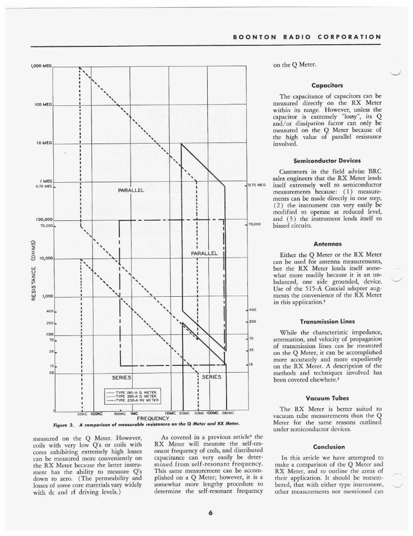
The fundamental differences between the RX Meter and the Q Meter may be briefly listed as follows: 1. The Q Meter provides a direct indi- cation of Q over a range of 5 to 1200 or 10 to 625, depending upon the model used. Higher Qs, up to the order of several thousand, can be readily meas- ured by indirect methods. The RX Meter is basically a low-Q device and will measure Q to zero. RX Meter readings are direct in equivalent parallel capaci- tance and resistance, and Q must be computed from these readings. 2. In the transition from direct to in- direct measurements on the Q Meter, there is a gap in the range of resistances which can be measured. The RX Meter is on the other hand, calibrated directly in parallel resistance, and resistance measurements can be made in a con- tinuous range of from 15 to 100,000 ohms. A comparison of the values of resistance that are measurable on the RX Meter and the Q Meter is shown in Figure 2. 3. The 260-A Q Meter operates in a range from 50 kc to 50 mc and the
LJ Figure 1. The author loads one of BRC’s station wagons before taking off on a field trip. This field service brings our full line of instruments to the customer‘s door. Actual demonsfra- tions and technical consultation assist the customer with problems and in selecting fhe correct instrument for the job to be done.
190-A Q Meter operates in a range from 20 to 260 mc. Operating in a range from 500 kc to 250 mc, the RX Meter frequency range is almost equiv- alent to the total range of both Q Meters. 4. The resonating capacitance of the RX Meter goes down to zero, whereas the minimum capacitance of the 190-A 0 Meter is 7 ppf and the minimum capacitance on the 260-A Q Meter is 30 ppf. Coils requiring very low values of resonating capacitance can not be resonated on either of the Q Meters, but can be resonated on the RX Meter. 5. Voltage applied to the specimen in making measurements on the Q Meters is a function of the setting indicated by the XQ Meter, and is for the most part determined by the Q of the coil to be measured. The applied voItage of the RX Meter varies from 0.1 volt to 0.5 volts, but can, with the addition of an external potentiometer, be made to vary to a minimum of 0.02 volts. This feature of the RX Meter is partidarly desirable when it is necessary to measure input circuits to tube grids or transistors, where the impedance can be influenced
by the level at which it is measured.‘ 6. Since the insertion voltage of both types of Q Meters is developed between the low coil side and ground, neither side of the inductance is at ground RF potential. This, as a consequence, does not permit series type measurements to be made with one side at ground RF potential. The RX Meter is a grounded- type bridge and therefore measurements can be made with a common RF ground established between the bridge and the circuit under consideration.
Common Measurement Problems
It might be well at this point to con- sider how the fundamental differences between the Q Meter and RX Meter affect components and circuits under investigation. With these differences under consideration, let us list the sev- eral major measurement categories and determine which instrument is best suited for a particular measurement job.
Coils
As pointed out above the Q of high-Q coils can be best and most expeditiously
5
B O O N T O N R A D I O C O R P O R A T I O N
I
I SERIES
1,000 MEG
IO0 MEC
I O MEC
I MEC 0.75 ME(
I OO,OO( 70,001
n v) I I 8 l0,OOl
w V z
2 w 1,001 v)
LL
40
20
I O 7
3
I
I
--- -- \ ’ ’ .
\
’ I S I I
I I I I I I I I
I I I I I I I I I I I I I I
I I I I I I I I I I I
I I
I
I I I I I I I
I I I I I I
I
I
50KC 1
PARALLEL I
\ &
I I I I I I
I -I
I I I I I I I
PARA1 I
I I I I I I I I
I I I
)MC 260MC
Figure 2. A comparison of measurable resistances on the Q Mefer and RX Meter.
measured on the Q Meter. However, coils with very low Q s or coils with cores exhibiting extremely high losses can be measured more conveniently on the RX Meter because the latter instru- ment has the ability to measure Q s down to zero. (The permeability and losses of some core materials vary widely with dc and rf driving levels.)
).75 MEG
10,000
400
200
70
35
15
As covered in a previous article’ the RX Meter will measure the self-res- onant frequency of coils, and distributed capacitance can very easily be deter- mined from self-resonant frequency. This same measurement can be accom- plished on a Q Meter; however, it is a somewhat more lengthy procedure to determine the self-resonant frequency
on the Q Meter.
Capacitors
The capacitance of capacitors can be measured directly on the RX Meter within its range. However, unless the capacitor is extremely “lossy”, its Q and/or dissipation factor can only be measured on the Q Meter because of the high value of parallel resistance involved.
Semiconductor Devices
Customers in the field advise BRC sales engineers that the RX Meter lends itself extremely well to semiconductor measurements because: ( 1 ) measure- ments can be made directly in one step, ( 2 ) the instrument can very easily be modified to operate at reduced level, and ( 3 ) the instrument lends itself to biased circuits.
Antennas
Either the Q Meter or the RX Meter can be used for antenna measurements, but the RX Meter lends itself some- ~
what more readily because it is an un- balanced, one side grounded, device. Use of the 515-A Coaxial adapter aug- ments the convenience of the RX Meter in this application.*
Transmission lines
While the characteristic impedance, attenuation, and velocity of propagation of transmission lines can be measured on the Q Meter, it can be accomplished more accurately and more expediently on the RX Meter. A description of the methods and techniques involved has been covered else~here.~
Vacuum Tubes
The RX Meter is better suited to vacuum tube measurements than the Q Meter for the same reasons outlined under semiconductor devices.
Conclusion
In this article we have attempted to make a comparison of the Q Meter and RX Meter, and to outline the areas of their application. It should be remem- bered, that with either type instrument, other measurements not mentioned can
. .
4
6
r
T H E N O T E B O O K
be made using suitable but perhaps more indirect techniques. Generally speaking, it can be said that measure- ments that can be handled on either instrument, with the exception of di- electric measurements and measurement of high-Q coils, can be performed more expediently on the RX Meter.
’. 2.
References No. 3, Fall 1954.
Riemenschneider, N. L., “Some VHF Bridge Applications,” BRC Note- book No. 6, Summer 1955. Gorss, C. G., “A Coaxial Adapter for the RX Meter,” BRC Notebook
3.. Riemenschneider, N. L., “Transmis- sion Line Measurements with the RX Meter,” BRC Notebook No. 3, Fall 1954.
Use Of Markers On Sweep Signal Generator Type 2 4 0 4
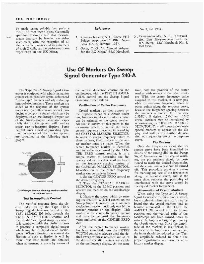
The Type 240-A Sweep Signal Gen- erator is equipped with a built-in marker system which produces crystal-referenced “birdie-type” markers and adjustable pip interpolation markers. These markers are added to the response of the system under test, (see illustration below) pro- ducing a composite signal which may be displayed on an oscilloscope. PFoper use of the Sweep Signal Generator, espe- cially the marker system, will produce sharp, easy-to-interpret displays. Some helpful hints, aimed at providing opti- mum operation of the marker system, are contained in the following para- graphs.
Oscilloscope display showing markers added io response curve.
Test in Amplitude Control
The rectified response from the cir- cuit under test by the Type 240-A Sweep Signal Generator is fed to the TEST SIGNAL IN jack, through the TEST IN AMPLITUDE control, and then to the Test Signal Amplifier where it is combined with the birdie markers to produce a composite signal output which may be displayed on an oscil!o- scope. When adjusting the vertical de- flection of such a display, it will be found that best results are obtained when adjustment is made by means of
the vertical deflection control on the oscilloscope, with the TEST IN AMPLI- TUDE control on the Sweep Signal Generator turned full on.
Verification of Center Frequency
Crystal markers, as they appear on the response curve of a circuit under test, have no significance unless a value can be assigned to the center marker. All that is known at this point in the measuring procedure, is that the mark- ers are frequency spaced as indicated by the CRYSTAL MARKER SELECTOR. In order to assign frequency values to these markers, identification of the cen- ter marker must be made. When the center frequency marker is identified and its value ascertained by the CEN- TER FREQ control setting, it is a simple matter to determine the fre- quency values of other markers based on the frequency spacing setting of the CRYSTAL MARKER SELECTOR. Identification of the center frequency marker can be made as follows:
1. Set the CENTER FREQ control to the desired frequency.
2. Turn the CRYSTAL MARKER SELECTOR to the 2.5MC position and observe the markers on the oscilloscope display.
3 . Narrow the sweep width by turn- ing the SWEEP WIDTH control on the Sweep Signal Generator in a counter- clockwise direction untiI only one birdie marker remains on the display. This marker is the center frequency marker and may be assigned the frequency value indicated on the CENTER FREQ dial.
After the center frequency marker has been identified, turn the SWEEP WIDTH control clockwise until the de- sired sweep width is obtained and all of the desired 2.5 MC markers are visible on the oscilloscope display. At the same
time, note the position of the center marker with respect to the other mark- ers. With the center frequency value assigned to this marker, it is now pos- sible to determine frequency values of other points along the response curve, because the frequency spacing between the markers is known (in this case 2.5MC). If desired, .5MC and .lMC crystal markers may be introduced by repositioning the CRYSTAL MARKER SELECTOR. This will cause more closely spaced markers to appear on the dis- play, and will permit further delinea- tion of frequencies along the response curve.
Pip Markers Once the frequencies along the re-
sponse curve have been identified by means of the tuning dial on the Sweep Signd Generator and the crystal mark- ers, the pip markers should be posi- tioned to mark the desired frequencies, and the crystal markers should be turned off. This procedure provides a means for marking any two of the frequencies along the response curve, and at the same time, removes the possibility of interference with the curve caused by the crystal marker frequencies.
Attenuation of Crystal Markers When using the Type 240-A Sweep
Signal Generator to test a circuit which has a high-gain characteristic, it may be found that the crystal markers tend to become attenuated if the TEST IN AMPLITUDE control is in its full-on position and the vertical gain of the oscilloscope has been turned down to reduce the high level signal put out by the circuit under test. Since the ampli- tude of the markers is insufficient in the face of the high test circuit output, the input should be reduced or the “Test In” amplitude reduced to obtain the proper signal-to-marker ratio for satis- factory marker display.
7 1

BOONTON RADIO CORPORATION THE NOTEBOOK
EDITOR'S NOTE
Q Meter Survives Re-Entry
The 8-mile drive west on Route 46, from Mountain Lakes to Dover, New Jersey is an exciting safari. Deluxe beaneries, vari-colored gas pumps, sign- infested discount stores, glowing bill- boards, and other scenic wonders, too numerous to mention, are breathtaking, even on a dull day. On December 2 , during one of these treks from desk to dinner table, your editor was eye- witness to something he knows will be of extreme interest to Notebook read- ers, especially rocket enthusiasts and moonwatchers.
It was a little after 5 o'clock; the sun was not more than a few minutes be-
The small crowd that had gathered by this time, edged closer to the object, until those of us in the lead were within 5 feet of it. It was then that I got the surprise of my life. The object in the road was unmistakably a BRC Type 260-A Q Meter. This didn't seem pos- sible; after all, the object had fallen from the sky; but there it was.
within twentv feet of t h M & The Tvee 160-A 0 Meter shown soarinu throuuh ~. a few minutes however, the'object no
cooling rapidly. in operat ing condition.
space was actually received f o r repair af ter it
ne l at BRC were amazed to find the instrument
- - longered glowed, and appeared be had been damaged by fire. lnspecfion person-
ten minutes later, attired in volunteer firemen's garb, and convinced the local police that the instrument should be transported to the BRC laboratory for examination.
The instrument was examined with utmost care by Larry Cook, Quality Con- trol Engineer, Bob Barth, Inspection Foreman, and other BRC engineers, and a full report was prepared and pre- sented at a special board meeting held on Wednesday, December 4th. Copies of the report have been distributed to capital hill and interested government agencies. The contents remain confi- dential as this account goes to press, but I have been authorized by proper authority to disclose two unusual facts: the 260-A Q Meter was tested and found to be in good working order, (incredible as this may seem); the examiners noted what appeared to be the paw marks of a dog on the instru- ment's front panel.
ere are some Notebook readers,
sky. Note the damaged front panel. Naturally, for the sake of security, the paw marks have been cleverly removed by a retouch artist.
OTTOWA, Ontario, Canada INDIANAPOLIS 20, Indiana
INSTRUMENT ASSOCIATES EARL LIPSCOMB ASSOCIATES CROSSLEY ASSO'S., INC. 48 Sparks Street ARLINGTON 74, Massachusetts
5420 North College Avenue Telephone: CLifford 1-9255 1315 Massachusetts Avenue TWX: I P 545 Telephone: Mlssion 8-2922
TWX: ARL MASS 253
BlVlNS & CALDWELL CROSSLEY ASSO'S., INC. 1178 Los Altos Avenue Telephone: Tuxedo 4-3425 ROCHESTER 10, New York 3133 Mople Drive, N.E. 53 Pork Avenue Telephone: WHitecliff 8-7266
10s ANGELES, California Telephone: CEdar 3-7522
VAN GROSS COMPANY TWX: AT 987
E l PASO, Texas 21051 Costonso Street Telephone: LUdlow 6-4940 BINGHAMTON, New York
BAYLY ENGINEERING, LTD.
Telephone: CEntral 2-9821
PITTSBURGH 36, Pennsylvania H. E. RANSFORD COMPANY
@- DALLAS 9, Texas
P. 0. Box 7084 Telephone: FLeetwood 7-1881 TWX: DL 411
10s ALTOS, Colifornia ATLANTA, Georgia DAYTON 19, Ohio VAN GROSS COMPANY 5400 Cloirton Boulevard
Telephone: Axminster 9-3594 TWX: DY 306 E. A. OSSMANN & ASSOC., INC.
830 Linden Avenue
EARL LIPSCOME ASSOCIATES Post Office Box 425 TWX: RO 189 Woodland Hills, California 720 North Stonton Street
KEystone 2-7281 Teleuhone: Dlomond 0-3131
BlVlNS & CALDWELL NEW HAVEN 10, Connecticut Telephone: Mldwoy 6-7881
ST. PAUL 14, Minnesota E. A. OSSMANN 8 ASSOC., INC. 147 Front Street
Telephone: ENdicott 5-0296 HIGH POINT, North Carolina TWX: Canoga Park 7034 842 Raymond Avenue Vestal, New York CROSSLEY ASSO'C., INC.
BOONTON, New lersey 1923 North Main Street INSTRUMENT ASSOCIATES TWX: ST P 1181 SYRACUSE, New York BOONTON RADIO CORPORATION Telephone: High Point 3672 265 Church Street
Intervale Road TWX: HIGH POINT NC 454 Telephone: UNiversity 5-2272
Telephone: DEerfield 4-3200 HOUSTOl'bl Texas ORLANDO, Florida 308 Merritt Avenue TWX: BOONTON NJ 866
E. A. OSSMANN R ASSOC., INC.
EARL LIPSCOMB ASSOCIATES BlVlNS & CALDWELL Telephone: Howard 9-3825
Telephone: JAckson 4-9303 Telephone: CHerry 1-1091 TORONTO, Ontario, Canoda BAYLY ENGINEERING, LTD. First Street Ajax, Ontario, Canada Telephone: Aiax 118
P. 0. Box 6573 1226 E. Colonial Drive
(Toronto) EMpire 8-6866
CHICAGO 45, Illinois CROSSLEY ASSO'S., INC. 271 1 West Howord St. Telephone: SHeldroke 3-8500 TWX: CG 508
NEW JERSEY
d
d
Printed in U.S.A.
8