3.2 towards a thermally robust automotive pre-chamber
TRANSCRIPT

3.2 Towards a Thermally Robust Automotive Pre-Chamber Spark Plug for Turbocharged Direct Injection Gasoline Engines
Peter Janas, Werner Niessner
Abstract This study presents a first step towards a thermally robust passive pre-chamber spark plug for boosted direct injection gasoline engines, where the pre-chamber spark plug is used to precisely control the start of combustion, increase the engine efficiency, while decreasing pollutant emissions and providing a more stable combustion, com-pared to conventionally initiated combustion with a j-gap spark plug. The here pre-sented passive pre-chamber spark plug can be integrated into an existing cylinder head design without introducing additional components. A new passive pre-chamber spark plug is proposed based on a surface discharge electrode configuration, in order to extend the operating range of a previously devel-oped pre-chamber spark plug using a two pin ground electrode configuration. The new passive pre-chamber spark plug is based on a patented surface discharge concept (GB 2 361 264 A), which allowed us to create a barrier-free pre-chamber working vol-ume, to better control the residual gas distribution, turbulence and flame front propa-gation inside the pre-chamber. The key parameters of the pre-chamber, such as pre-chamber volume and hole diameter were estimated in a first step by using a simple gas displacement model and by 3D heat transfer simulations, using thermal boundary conditions under typical full-load operating conditions. Furthermore, in order to better understand the inner physical phenomena of our passive pre-chamber spark plugs, additional 3D CFD simulations of the turbulent mixing and subsequent combustion were carried out by means of large eddy simulations (LES). The LES simulations only considered the pre-chamber volume and were solely applied for the compression stroke. The influence of the engine was modelled as time depended boundary condi-tions coming from 0D simulations. Combustion was modelled by a flame surface den-sity approach and ignition initiated by an increase of the flame surface density in a spherical volume in the vicinity of the spark plug. The 3D CFD simulation revealed a strong sensitivity of the residual gas distribution and turbulent flow field to the pre-chamber orifice and inner volume geometry, which influenced the combustion progress inside the pre-chamber significantly. First promising experiments on an engine test bench with the new barrier-free concept were conducted, where the working envelop could have been extended compared to our previously developed two-pin pre-chamber spark plug design.
122

3.2 Towards a Thermally Robust Automotive Pre-Chamber Spark Plug for Turbocharged Direct Injection Gasoline Engines
1 Scope and Motivation
In order to cope with the more stringent emission regulation of today's passenger car vehicles, OEMs have to increase the efficiency, while reducing the pollutant emissions of the already highly sophisticated thermal combustion engines. The window for im-provements can only be extended by the introduction of new key technologies. A prom-ising technology for passenger car sized engines is the pre-chamber spark plug, which is in turn not a brand new invention and known for 100 years (US patent 1365143). It never reached the maturity for mass production, except for Honda’s CVCC engine [35] in 1975. A review on pre-chamber spark plugs for automotive applications can be found in the work of Alvarez et al [4]. Its reconsideration for automotive application was re-cently triggered by MAHLE’s torch ignition system [28] and by some successfully ap-plied pre-chamber spark plugs for racing engines.
Figure 1: Passive Pre-chamber spark plug (left) and cut through the symmetry plane showing a simplified inner-geometry of the pre-chamber volume, including ground
and center electrode (right). Also very recently in a feasibility study on pre-chamber plugs by Sens et al. [22], em-phasis was put on its potential for the future of highly efficient spark ignition engines, where they have operated an in-house developed pre-chamber spark plug system un-der varies engine operating conditions with promising results on fuel efficiency and the reduction of pollutant emissions. A pre-chamber spark plug is composed of an ordinary spark plug with electrodes, on which a cap, also known as pre-chamber, is put. An example of a passive pre-chamber spark plug is shown in figure 1. The encapsulated volume represents a second com-bustion chamber, which is connected to the main chamber by orifices. Different kinds of pre-chamber spark plug systems exist, which can be classified into active [29] and passive systems. The active pre-chamber system is equipped with an additional fuel and/or air injector inside the pre-chamber, which allows to precondition the mixture, whereas a passive pre-chamber realizes its gas exchange solely by the pressure dif-ference between pre- and main-chamber and of course by the local flow field in the vicinity of the orifices. In the scope of completeness, results based on both systems, active and passive, will be discussed in the following, due to similar working principles
123

3.2 Towards a Thermally Robust Automotive Pre-Chamber Spark Plug for Turbocharged Direct Injection Gasoline Engines
and physical phenomena. No clear distinction between passive and active is made for the ongoing discussion in this chapter. The benefits that a pre-chamber spark plug can deliver are the following:
Ignition of lean main combustion mixtures Reduction of NOx emissions by lower overall combustion temperatures.
Faster combustion progress Knock mitigation by competing with the auto ignition delay time of the cylinder end gas.
Reduced turbulence inside engines with a low tumble flow can be compen-sated by the turbulence created by the flame/hot burned gas jets.
Diluted mixtures with a high amount of residual gasses can be faster burned Reduction of the laminar flame speed due to residual gasses are compen-sated by multiple ignition sources initiated by the hot gas/active radial jet and turbulence produced by the emitted jets.
Igniting at multiple locations increases the probability of the main combustion chamber charge ignition Reduction in cycle-to-cycle variations (CCV).
Shorter flame travel time towards the piston top-land crevice Reduction in unburnt hydrocarbon emissions (UHC).
Active control of the turbulence in specific areas inside the main combustion chamber Complementing technology to Miller/Atkinson cycle.
Similar performance as HCCI, which lacks of control due to high sensitivity to temperature stratification.
It has to be mentioned that the aforementioned benefits may not be all achieved to-gether for one particular application, hence the design of the pre-chamber will be highly dependent on the motivation of the OEM. Nowadays, pre-chamber spark plugs, active or passive, are successfully used in big bore stationary gas engines. One can easily understand that a bigger engine will have less packaging constraints as a passenger car-sized engine, in first place, and secondly the calibration for a single operating point reduces the design tremendously, compared to high transients, as one can find in mod-ern downsized gasoline engines. Within this study, we propose a new barrier free passive pre-chamber system for mod-ern gasoline passenger car sized engines and compare it to a previously developed two-pin passive pre-chamber design. Emphasis is put on an efficient development workflow, which should allow to quickly assess many operating conditions and different pre-chamber geometrical parameters. Therefore, 0D simulations, 3D thermal analysis and “pre-chamber-only” CFD simulations by means of large eddy simulations were developed and applied exemplarily for a fictive engine. Finally, first experimental re-sults of our pre-chamber systems are presented.
1.1 State of the art
In the past a lot studies were conducted to find the optimal design parameter of a pre-chamber spark plug. The majority of the literature sees the pre-chamber orifices as a key-parameter, and performed experimental and numerical analysis on the orifice size ([18] [14] [11] [16] [22] [26] [28] [31] [32] [33]), using orifice diameters from 0.8 mm [22] up to 4.5 mm [33]. There is no clear consensus on an orifice diameter, since it depends on many parameters such as the fuel properties, thermodynamic conditions inside the pre- and main chamber, governed by the local flow conditions inside the pre-chamber
124

3.2 Towards a Thermally Robust Automotive Pre-Chamber Spark Plug for Turbocharged Direct Injection Gasoline Engines
during the compression stroke and the jet velocity of the hot burned gas and/or active radical stream towards the main combustion chamber. Most of the studies used me-thane as fuel ([16] [15] [18] [26] [10] [11] [31] [33]), but also experiments with propane ([12] [14]) ethylene [18], CNG for direct injection [22], gasoline ([21] [22] [28]) and H2 ([17] [33] [34]) can be found. For example Roethlisberger, R. P. et al. studied numeri-cally [8] and experimentally [9] an unscavenged pre-chamber system inside a modified Liebherr type 926 engine powered with natural gas. They revealed that, on the one hand, by decreasing the orifice diameter, the velocity/turbulence intensity inside the pre-chamber will increase, which can cause misfire by too high flow velocities in the vicinity of the spark gap. On the other hand, they experimentally demonstrated, that not only the flow velocity into the pre-chamber increases, but also the velocity of the flame torch jets coming out of the pre-chamber, leading to an earlier flame arrival at the piston top-land crevice, which reduces the unburnt hydrocarbon emissions (UHC). The orifice diameter is of key importance, because it has to work, literally, in two senses, (a) towards the pre-chamber as an induction device and flow field precondi-tioner and (b) as an exhaust nozzle, which creates an ignition jet that leads to a multiple ignition source (ideally with low wall contact, to reduce heat losses). Therefore, not only the size of the hole is important, but also its orientation inside the cap, where different orientations have been examined in the literature, such as by Baumgartner et al. [31], who used a 45° and 70° hole orientation relative to the spark plug vertical axis and demonstrated that an orientation towards the top-land crevice region, decreases the UHC emissions. Another influencing parameter for the inner aerodynamics of the pre-chamber and jet pattern inside the main chamber is the number of orifices. Orifice numbers from one up to eight can be found in the literature ([22] [26] [14] [16] [28] [11] [31] [32]), where it was found that the probability of ignition inside the main chamber increased with the number of orifices, hence ignition locations. The number of holes, however, is limited by the total effective area, which will govern the pressure drop, hence the filling and scavenging of the pre-chamber volume. This leads us to the next important global de-sign parameter of the pre-chamber, which is the volume of the pre-chamber itself. Also here, different volumes have been investigated in the literature. The volume of the pre-chamber is usually given in % relative to the clearance volume of the main chamber volume at top-dead-center (TDC). The values found in the literature range from 1.9% to 3.5%, where the majority use 2% ([12] [28] [21] [22]). Nakazano et al. [3], for exam-ple, studied experimentally in 1994 the effect of the volume (2% - 3% of the engine’s clearance volume) and orifice diameter of an actively scavenged and water cooled pre-chamber. They discovered that an increase of the pre-chamber volume led to an in-crease in combustion speed and the NOx emissions. Experiments done by Roethlis-berger, R. P. [9] with different pre-chamber volumes showed, that the cycle-to-cycle variations (CCV) decreased by decreasing the pre-chamber volume, but the UHC emissions increased. The reduction of CCV was attributed to smaller turbulence inten-sities inside the pre-chamber volume and the higher UHC due to shorter flame torches, which will later arrive at the crevice regions. Another critical dimension is the length of the orifice, which is usually expressed rela-tive to the orifice diameter. This value is, to the best of the authors’ knowledge, not so extensively studied, since the orifice channel is experimentally unavailable and by means of CFD extremely difficult to account for (a) the heat transfer, (b) flow restriction by boundary layer development (if any) and (c) flame quenching effects. Akhtar et al.
125

3.2 Towards a Thermally Robust Automotive Pre-Chamber Spark Plug for Turbocharged Direct Injection Gasoline Engines
[16] did not change the length of the orifices, but did study experimentally the influence of the orifice geometry inside a constant volume chamber with optical access. They revealed that slit holes produced a deeper flame torch penetration compared to con-ventional round holes. They claimed that the slit type orifice produced more turbulence and longer jets. In order to get a feeling of the interaction of the aforementioned geometrical features of the pre-chamber spark plug (pre-chamber volume, orifice diameter, length and num-ber of orifice) a 0D model was developed by Bardis et al. [24], which allows to calculate the turbulence intensity and length scales during the compression stroke inside the pre-chamber prior to ignition. This approach requires the calibration of many model constants with CFD and experimental data. Obviously, the identification of the model constants will be restricted to a particular engine and pre-chamber design, but once calibrated, it delivers very quickly a global overview about the inner flow and thermo-dynamic conditions over the entire operating range of the engine, which is in particular very interesting for pre-chamber applications of passenger car sized engines. Also Sens et al. [22] used a 0D model to investigate the boundaries of their pre-chamber design and the importance of the global heat losses during the combustion phase. Another 0D model for the pre-chamber combustion and torch ignition was developed by Kenji et al. [25]. They treated the ejected hot gass as a classical free jet with air entrainment. They compared their model to experimental evidence of a single cylinder gas engine (170 mm bore and 220 mm) and obtained a good qualitative and quantita-tive agreement. Also the material of the cap plays an important role, since the cap is projected into the main chamber and exposed from both sides to temperature over 2000 K. For example Sens et al. [22] used steel and copper caps and Yoshitane et al. [11] steel, aluminum and even ceramic. Yoshitane et al. observed that the bulk flow temperature inside the pre-chamber was 100 °C cooler for a pre-chamber made out of aluminum than out of stainless steel over a lambda range of 1.0-1.6. On the one hand, reducing the thermal conductivity of the pre-chamber material increases the gas temperature in the pre-camber volume, but on the other hand, it stabilizes the jets, shortens the early-phase of combustion and extends the lean limit. Koji et al. [10] studied experimentally the heat range of a passive pre-chamber spark plug with thermocouples inside the pre-chamber cap, ground electrode and center electrode. They measured the hottest temperatures (>800 °C) at the ground electrode, which was based on a Rhodium Iridium alloy. They showed that by retarding the spark timing (from 35°CA bTDC to 18°CA bTDC), the outer cap component temperature de-creased from 850°C to 600°C. In many experimentally studies, hypothesis on the jet dynamics have been made based on the tail end pipe emissions and in-cylinder pressure curve, which is not suf-ficient. Transparent engines would be perfect means to shed light on the jet dynamics, however, conclusions drawn from them might be biased from the particular engine flow conditions and not generically applicable. The already wide scatter on different com-pression ratios used for the engine experiments, makes the comparison even more difficult (10:1 [21],14:1 [22], 11.2:1 [10], 9.7:1 [31]). Therefore, research on the outflow-ing jet dynamics is conducted in rapid compression machines (RCM) in the vast ma-jority of literature ([19] [13] [15] [14] [12]). Due to its easier optical accessibility, Schlie-ren images and OH* chemiluminescence measurement techniques can be applied,
126

3.2 Towards a Thermally Robust Automotive Pre-Chamber Spark Plug for Turbocharged Direct Injection Gasoline Engines
which can show the morphology of the jet, jet penetration length, and position of active radicals, which is an indication of an actively burning flame front. However, high speed images of the hot jets can also be obtained in real engines, as shown by Sens et al. [22]. Another interesting test vessel and widely used in academia is a constant volume chamber, which allows the application of optical diagnostics, too ([33] [34] [17] [16]). Allison et al [18] even used a complete transparent pre-chamber, having the unique feature to study the flame propagation inside the pre-chamber. Using the aforemen-tioned devices allowed them to make more fundamental studies on the flame torch species concentration ([21] [17]), the jet velocity coming out of the pre-chamber ([21], [18] [26] [17]), vorticity in the main chamber [17] and jet-to-jet interaction [34]. A strong correlation of the ignition position inside the pre-chamber to the jet penetration could be found by many authors ([18] [14] [22] [10] [11] [33] [34]), saying spark location has a deterministic effect on the jet penetration length and strength. For example Thelen et al. [14] studied the spark location inside the pre-chamber in regards to the flame torch development, where the furthest possible position away from the orifices yielded the strongest jet into the main chamber, hence the best combustion performance. The slowest onset of pre-chamber combustion was observed while igniting in the middle of the pre-chamber. The highest amount of cold unburnt mixture is ejected for the spark locations the furthest away from the orifices. The slowest onset of combustion inside the main chamber was observed for the case, where combustion was triggered close to the orifices. During the last years the picture of the jet shape, structure and its sensitivity to the global pre-chamber parameters became more complete. It is now understood that de-pending on the spark location and orifice diameter the content of the ejected jet out of the pre-chamber will change. In the beginning of the ejection phase, residual gases lying ahead of the flame front will be expelled, followed by the flame front, which (a) can be quenched depending on the orifice diameter or (b) passing through. Hereby, two different ignition mechanisms are identified by Bisawis et al. [33], depending whether the flame is quenched or not. Bisawis et al. [33] proposed a global Damköhler number to distinguish jet and flame ignition and introduced a critical limit, under which ignition inside the main chamber was not possible anymore. In an extension to this work, Bisawis et al. [17] studied the ignition mechanism inside the main chamber with different orifice geometries. By introducing a Laval nozzle type orifice, they were able to introduce jets with higher overall temperature, but also higher velocities along the jet axis. They revealed that a high temperature is not sufficient to initiate combustion in the main chamber, but also a not too high turbulent jet intensity.
2 Pre-Chamber concepts
Within this work two different pre-chamber concepts are tested; a concept which uses two pins as ground electrode and one which is based on a surface discharge working principle. The two pin electrode pre-chamber spark plug will be denoted for the sake of simplicity as “2Pin” and the surface discharge spark plug as “SD”. Figure 2 shows a sketch of the two concepts, where for the SD concept, two different hole orientations are considered.
127

3.2 Towards a Thermally Robust Automotive Pre-Chamber Spark Plug for Turbocharged Direct Injection Gasoline Engines
Figure 2: Sketch of the pre-chamber spark plug with 2Pin ground electrode (left) and of the pre-chamber spark plug with the surface discharge electrode configuration with
radial orifices (middle) and radial-tangential orifices (right). The 2Pin and SD pre-chamber spark plugs have very similar pre-chamber volumes and differ mainly in the spark location. The 2Pin electrode version (Figure 2, left picture) has two spark locations, which are positioned close to the orifices, where the SD ver-sion has four different spark location in the circumferential region of the insulator. The spark discharge will not happen in the air-gap, as for the 2Pin plug, but literally slide on the surface of the insulator from the center electrode to the ground electrode. As a discharge over a surface requires lower voltage, a longer spark becomes possible. The reasons for using a surface discharge ignition concept are as follows:
Combustion chamber was desired without any obstacles to the flow, in order to better control the inner aerodynamics.
Reduction of the overall thermal behavior of the bulk flow and surface tempera-tures.
Spark location, which is at the upper position inside the pre-chamber (away from the orifices), which should be beneficial for the flame propagation and sub-se-quential pressure build-up in the pre-chamber (see discussion chapter 1.1).
Better mixing of the residual gases in the core nose region. All has to fit in a conventional M12 spark plug.
As mentioned above in the literature review, typical pre-chamber volumes are in the range of 1.9%-3.5% of the engine clearance volume. Since, one of the pre-chamber target is to exploit higher compression ratios (assumed 14:1) it was started with a rather small pre-chamber volume Vpc/Vclear of roughly 1.3% compared to the literature. It has to be stressed that none of the literature (to the best of the authors’ knowledge) pro-vides a generic explanation of the “right” volume, they only show trends derived from a baseline volume. It was also not the intention of the authors’ to optimize the break-down voltage demand at this state. The pre-chamber volume is fixed and its influence only discussed based on 0D simu-lations. Table 1 summarizes the main differences of the two concepts.
128

3.2 Towards a Thermally Robust Automotive Pre-Chamber Spark Plug for Turbocharged Direct Injection Gasoline Engines
Table 1: Specification of the two pre-chamber spark plug concepts for the 0D simula-tion. For the engine tests, the hole diameter in parenthesis are applied.
2Pin SD – Radial SD - Cross Volume 375 mm3 399 mm3 399 mm3 Spark loca-tion
2 sparks location within cap volume
4 spark locations at core nose region
4 spark locations at core nose region
# holes 4 4 4 Ø holes [mm] 1.0 (1.2) 1.2 (1.0) 1.0 (1.0) Orientation Radial Radial Radial-Tangential Cap material Nickel alloy Nickel alloy Nickel alloy
3 Numerical investigation
In order to access the performance of the inflow conditions during a wide range of operating conditions, simple 0D simulations are performed within the compression stroke for two different engine configurations. In a next step, the thermal behavior is investigated based on a typical full load operation and the flow inside the pre-chamber by means of large eddy simulation during the compression stroke studied. The flow fields are then used to initialize the combustion simulations. The individual development steps are now discussed in detail.
3.1 0D analysis
Inspired by the work of Bardis et al. [24], a 0D model is developed, which describes the flow and thermodynamic properties inside an un-scavenged pre-chamber during the compression stroke. The pre-chamber and cylinder volume are treated as two sep-arated open systems, which are communicating via an orifice. The mass, which is transported out from one volume is equal to the mass, which is flowing in the other, hence the total mass of the system must be constant. (Neglecting for the moment the gas exchange phase – Intake and Exhaust stroke). The subscript Pc denotes pre-chamber and Mc main-chamber.
Figure 3: Pre-chamber and main-chamber system illustration for the 0D model.
Figure 3 shows a sketch of the two control volumes (C.V.) For the sake of complete-ness the governing equations (1-4) will be shown, which read in differential form:
C.V.: Pre-chamber
C.V.: Main chamber
Dpc
L pc
129

3.2 Towards a Thermally Robust Automotive Pre-Chamber Spark Plug for Turbocharged Direct Injection Gasoline Engines
𝑚 𝑐 , 𝜕𝑇
𝜕𝑡𝜕𝑄
𝜕𝑡𝑝
𝜕𝑉𝜕𝑡
𝜕𝑚𝜕𝑡
ℎ 𝑒 (1)
𝑝𝜕𝑉
𝜕𝑡𝑉
𝜕𝑝𝜕𝑡
𝑚 𝑅 𝜕𝑇
𝜕𝑡𝑇 𝑅
𝜕𝑚𝜕𝑡
(2)
𝑚 𝑐 , 𝜕𝑇
𝜕𝑡𝜕𝑄
𝜕𝑡𝜕𝑚
𝜕𝑡ℎ 𝑒
(3)
𝑝𝜕𝑉
𝜕𝑡𝑉
𝜕𝑝𝜕𝑡
𝑚 𝑅 𝜕𝑇
𝜕𝑡𝑇 𝑅
𝜕𝑚𝜕𝑡
(4)
In the governing equations (1-4), p denotes the pressure, T the temperature, m the mass, cv the specific enthalpy under constant volume, R the universal gas constant, h the enthalpy, e the internal energy and Q the heat losses. The heat transfer coefficients for the convective heat losses inside the pre-chamber are modelled by the Bargende correlation [45] and inside the engine with the Woschni correlation [46]. A simplified model for the turbulent kinetic energy k, which takes into account the generation of turbulence created by the incoming jet, is used. A detailed description can be found in the work by Bardis et al. [24] and Hiraoka et al. [44]. The here used turbulence model reads:
𝜕 𝑚 𝑘𝜕𝑡
𝜂 𝑚𝑢
2𝑚
2𝑘/3 /
𝑙 (5)
With 𝑢 being the incoming jet velocity, 𝜂 describing the fraction of how much tur-bulence is produced by the jet (assumed 0.5 % of the kinetic energy is converted into turbulence) and 𝑙 the integral length scales according to Hiraoka et al. [44].
3.1.1 Assumptions and boundary conditions
Two fictive engines are used for the 0D analysis to investigate the influence of the global pre-chamber parameters. The two engine configurations only differ in the com-pression ratio, where engine 1 exhibits a compression ratio of 10:1 and engine 2, a compression ratio of 14:1. A detailed description of the engine configuration and the corresponding pre-chamber set-up is shown in table 2. Table 2: Specification of two fictive engines used for the 0D simulations and operat-
ing conditions. Engine 1 Engine 2
Bore [m] 0.07 0.07 Stroke [m] 0.09 0.09 Conrod length [m] 0.13 0.13 Compression ratio [-] 10:1 14:1 PC-Volume [mm3] 395 395 Vpc/Vclear [%] 1.0 1.4 No. Holes 4 4 Ø Holes [mm] 1 1 Engine Speed [rpm] 1500/3500/6500 1500/3500/6500 In-cylinder pressure at BDC [bar] 1.0 1.0 PC Wall temperature [K] 600 600
130

3.2 Towards a Thermally Robust Automotive Pre-Chamber Spark Plug for Turbocharged Direct Injection Gasoline Engines
An in-cylinder pressure of 1 bar is chosen as initial condition for the 0D simulation and an in-cylinder temperature of 300 K at BDC. The same initial conditions are used for the pre-chamber. The pre-chamber wall temperature is assumed to be 600 K. Three different engine speeds are considered: low (1500 rpm), medium (3500 rpm) and high (6500 rpm) engine speed. Standard model constants from the literature are used for all models and no calibration of the model constants carried out. Three consecutive compression and expansion strokes are calculated to ensure a statistically converged solution. A sensitivity analysis of the model constants and its calibration is not intendent in first place, rather to observe first qualitative trends. However, a recalibration of the model can be considered, once the pre-chamber design has been fixed and 3D CFD simula-tion and experimental data are available.
3.1.2 Results 0D: Influence of the compression ratio
Figure 4 shows 0D simulation results of the pre-chamber within the compression stroke for the two engines presented in table 2 and comprises (a) the pressure difference between pre- and main-chamber, (b) the inflow velocity into the pre-chamber, (c) the pre-chamber temperature, and (d) the turbulent kinetic energy (TKE) inside the pre-chamber. The results of engine 2 (CR 14:1) are presented with thin lines and symbols and the results of engine 1 (CR 10:1) with thick bold lines. The different engine speeds are illustrated by different colors.
Figure 4: 0D results for a fictive engine with 10:1 and 14:1 compression ratio. Red
dot shows example for max. velocity taken for study in figure 5.
(a) (b)
(c) (d)
131
3.2 Towards a Thermally Robust Automotive Pre-Chamber Spark Plug for Turbocharged Direct Injection Gasoline Engines
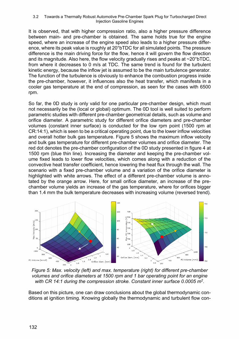
It is observed, that with higher compression ratio, also a higher pressure difference between main- and pre-chamber is obtained. The same holds true for the engine speed, where an increase of the engine speed also leads to a higher pressure differ-ence, where its peak value is roughly at 20°bTDC for all simulated points. The pressure difference is the main driving force for the flow, hence it will govern the flow direction and its magnitude. Also here, the flow velocity gradually rises and peaks at ~20°bTDC, from where it decreases to 0 m/s at TDC. The same trend is found for the turbulent kinetic energy, because the inflow jet is assumed to be the main turbulence generator. The function of the turbulence is obviously to enhance the combustion progress inside the pre-chamber, however, it influences also the heat transfer, which manifests in a cooler gas temperature at the end of compression, as seen for the cases with 6500 rpm. So far, the 0D study is only valid for one particular pre-chamber design, which must not necessarily be the (local or global) optimum. The 0D tool is well suited to perform parametric studies with different pre-chamber geometrical details, such as volume and orifice diameter. A parametric study for different orifice diameters and pre-chamber volumes (constant inner surface) is conducted for the low rpm point (1500 rpm at CR:14:1), which is seen to be a critical operating point, due to the lower inflow velocities and overall hotter bulk gas temperature. Figure 5 shows the maximum inflow velocity and bulk gas temperature for different pre-chamber volumes and orifice diameter. The red dot denotes the pre-chamber configuration of the 0D study presented in figure 4 at 1500 rpm (blue thin line). Increasing the diameter and keeping the pre-chamber vol-ume fixed leads to lower flow velocities, which comes along with a reduction of the convective heat transfer coefficient, hence lowering the heat flux through the wall. The scenario with a fixed pre-chamber volume and a variation of the orifice diameter is highlighted with white arrows. The effect of a different pre-chamber volume is anno-tated by the orange arrow. Here, for small orifice diameter, an increase of the pre-chamber volume yields an increase of the gas temperature, where for orifices bigger than 1.4 mm the bulk temperature decreases with increasing volume (reversed trend).
Figure 5: Max. velocity (left) and max. temperature (right) for different pre-chamber volumes and orifice diameters at 1500 rpm and 1 bar operating point for an engine
with CR 14:1 during the compression stroke. Constant inner surface 0.0005 m2.
Based on this picture, one can draw conclusions about the global thermodynamic con-ditions at ignition timing. Knowing globally the thermodynamic and turbulent flow con-
132

3.2 Towards a Thermally Robust Automotive Pre-Chamber Spark Plug for Turbocharged Direct Injection Gasoline Engines
ditions may help to estimate the combustion progress, however, it will not allow to pre-dict the ignitability of the pre-chamber charge, which is highly dependent on the local flow conditions in the vicinity of the spark plug. Here, 3D CFD simulations can be used to better understand the likelihood of ignition and the flame propagation path. 3D sim-ulation can also be used to calculate the component temperature, which is up to now a global parameter and will be discussed in the next subchapter.
3.2 Thermal investigation
Due to the complex shape of the inner volume, leading to locally different turbulent flow conditions, the heat transfer inside the pre-chamber is far too complicated to be easily calculated with a 0D model without thorough calibration.
3.2.1 Assumptions and boundary conditions
In order to have a better representation of the component temperature, 3D thermal simulations are performed under typical high load operating conditions. A convection boundary condition at an average gas temperature of 1200°C is applied on all walls and the influence of radiation taken into account.
3.2.2 Thermal results
Figure 7 shows the component temperature of the 2Pin and surface discharge spark plug. For the 2Pin spark plug, the hottest temperatures are found at the edge of the insulator and center electrode. The surface discharge spark-plug is overall cooler than the two-pin design. The insulator and center electrode are around 200 K and the cap temperature 90 K lower than the 2Pin design.
2Pin
Surface Discharge
Figure 7: Thermal simulation results of the component temperature of the 2Pin (left)
and surface discharge spark plug (right).
In the next step the aerodynamic performance, which will govern the residual gas dis-tribution and combustion is assessed.
133

3.2 Towards a Thermally Robust Automotive Pre-Chamber Spark Plug for Turbocharged Direct Injection Gasoline Engines
3.3 Cold flow analysis
Among the literature most of the numerical investigations are based on the RANS (Reynolds Average Navier-Stokes) approach, which gives an ensemble average of the flow field and completely relies on turbulence closure models, such as the two equation k-epsilon turbulence model. The RANS simulation approach can yield results within a few days, covering the complete engine cycle, including the gas exchange phase, spray formation, mixture preparation and pre- and main chamber combustion. These methods, however, require a tremendous effort in the tuning of varies model constants. A less model dependent approach, which can also predict the unsteadiness of the flow correctly, is the large eddy simulation (LES). Pre-chamber simulations using LES can be found in recent works of Allison et al. [18] and Gholamisheeri et al. [15]. Both LES simulations are not performed for an engine, where Allison et al. [18] studied the pre-chamber combustion inside a constant vessel and Gholamisheeri et al. [15] inside a rapid compression machine. Gholamisheeri et al. compared RANS and LES to chem-iluminescence images of the outflowing hot jet, where they obtained a better agree-ment with LES. Unlike the RANS approach, LES is based on a spatial filtering tech-nique, where the biggest scales, up to the size of the computational grid (cut-off length), are directly resolved. Only flow structures, which are smaller than the cut-off length, have to be modelled, where smaller scales are easier to model due to their isotropic character. LES requires high quality grids, accurate high-order numerical discretization schemes and relative small time steps (ideally, CFL < 1), which make the simulation computationally more demanding compared to RANS. Furthermore, in order to calcu-late turbulence depending properties, mean and fluctuating values need to be calcu-lated from a sufficient large number of statistical points. Within an engine this becomes even more complicated, because the computational domain is changing with time, which requires a phase-locked averaging method.
3.3.1 Assumptions and boundary conditions
In order to benefit from the accuracy of the LES approach, while bearing in mind the higher computational effort and numerical accuracy compared to RANS, only the pre-chamber will be considered. Pressure and temperature boundary conditions are de-rived from the 0D analysis of fictive engine 2 (see section 3.1.2) and directly imposed on the orifice entrance surface. It has to be mentioned that the development of the turbulent flow field is not discussed within this work nor velocity fields are shown. The flow development inside the pre-chamber is seen as a crucial parameter for the work-ing principle in regards of different engine speeds. The following assumptions are made for the cold flow analysis:
Pressure and temperature boundary conditions are taken from 0D modelling (Engine 2, CR 14:1) for 1500 rpm and 6500 rpm at 1 bar pressure at start of compression.
Turbulence is mainly generated by in-coming flow through the small orifices (as-sumed that turbulent length scales inside the engine are bigger than the orifice) No turbulence inlet generator used.
All walls have a fixed temperature of 600 K Pre-chamber is filled with 100% burnt gas of stoichiometric gasoline combustion
at the start of the simulation. Fresh mixture without residual burnt gasses is flowing into the pre-chamber. Only one compression stroke will be simulated (no mean values calculated).
134
3.2 Towards a Thermally Robust Automotive Pre-Chamber Spark Plug for Turbocharged Direct Injection Gasoline Engines
The Favre-filtered governing equation for mass, momentum and energy are solved using the finite volume method (FVM) with the open source software OpenFOAM [39], [40], [41]. The time is discretized by an implicit second order backward Euler scheme. The convective scalar-fluxes are discretized with a total variation diminishing scheme (TVD) using the Sweby limiter, where the convective fluxes of the momentum equation are calculated by a central differencing scheme (CDS). The compressibility of the flow is taken into consideration by a pressure-velocity-density approach proposed by Demirdžic [36] and a compressible version of the standard Smagorinsky model is used for the turbulent sub-grid scales fluxes [37] [38]. The computational grids are based on equidistant cubic cells with a cell size of 0.1 mm leading to 0.39 million cells for the SD- and 0.37 million for the 2Pin pre-chamber spark plug.
3.3.2 Results: Pre-chamber gas temperature
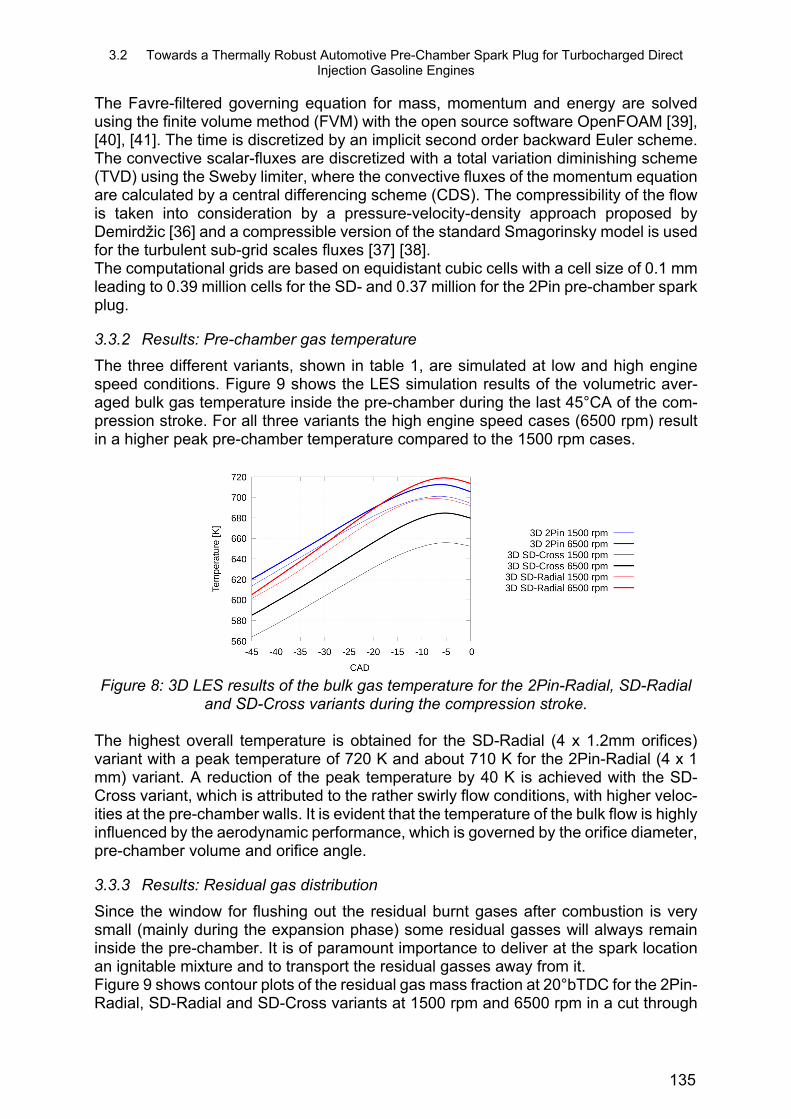
The three different variants, shown in table 1, are simulated at low and high engine speed conditions. Figure 9 shows the LES simulation results of the volumetric aver-aged bulk gas temperature inside the pre-chamber during the last 45°CA of the com-pression stroke. For all three variants the high engine speed cases (6500 rpm) result in a higher peak pre-chamber temperature compared to the 1500 rpm cases.
Figure 8: 3D LES results of the bulk gas temperature for the 2Pin-Radial, SD-Radial
and SD-Cross variants during the compression stroke.
The highest overall temperature is obtained for the SD-Radial (4 x 1.2mm orifices) variant with a peak temperature of 720 K and about 710 K for the 2Pin-Radial (4 x 1 mm) variant. A reduction of the peak temperature by 40 K is achieved with the SD-Cross variant, which is attributed to the rather swirly flow conditions, with higher veloc-ities at the pre-chamber walls. It is evident that the temperature of the bulk flow is highly influenced by the aerodynamic performance, which is governed by the orifice diameter, pre-chamber volume and orifice angle.
3.3.3 Results: Residual gas distribution
Since the window for flushing out the residual burnt gases after combustion is very small (mainly during the expansion phase) some residual gasses will always remain inside the pre-chamber. It is of paramount importance to deliver at the spark location an ignitable mixture and to transport the residual gasses away from it. Figure 9 shows contour plots of the residual gas mass fraction at 20°bTDC for the 2Pin-Radial, SD-Radial and SD-Cross variants at 1500 rpm and 6500 rpm in a cut through
135

3.2 Towards a Thermally Robust Automotive Pre-Chamber Spark Plug for Turbocharged Direct Injection Gasoline Engines
the vertical center plane (SD-Cross uses a different cutting face). A very low residual gas mass fraction is obtained (<5%) for the 2Pin-Radial variant at the electrode gap, from where the fresh gas is redirected towards the core nose region. For the SD-Radial variant, however, spots of 30 % residual gas mass fraction appear in the core nose region close to the ignition region for the 1500 rpm operating point. Due to the radial orientation of the 4 orifices, the 4 jets impinge at the insulator tip and form a recircula-tion zone, which hinders the fresh gasses reaching the spark location. Fortunately, for higher engine speeds, the unsteadiness of the impingement of the 4 radial jets (not shown here) allow the flow to reach the core nose region occasionally, yielding to a lower residual gas mass fraction. The SD-Cross variant has for 1500 rpm and 6500 rpm a low residual gas fraction in the vicinity of the 4 spark locations, since the jets are directly streaming towards the core nose zone and creating there a swirl motion.
2Pin 4 x 1 mm
SD–Radial 4 x 1.2 mm
SD–Cross 4 x 1 mm
Figure 9: Residual gas distribution in a cut through the symmetry plane at 20°bTDC at 1500 rpm and at 6500 rpm for the 2Pin-Radial (left), SD-Radial (middle) and SD-
Cross (right) variant. SD-Cross variant uses a different cutting face.
For a better visualization of the residual gas distribution at 20°bTDC, figure 10 shows only cells with a residual gas fraction higher than 20% in a 3D transparent version of the corresponding pre-chamber variants.
6500 rpm
1500 rpm
136

3.2 Towards a Thermally Robust Automotive Pre-Chamber Spark Plug for Turbocharged Direct Injection Gasoline Engines
Figure 10: Residual gas distribution in a cut through the symmetry plane at 20°bTDC for 1500 rpm showing only region with a residual gas fraction higher than 20%.
3.4 Pre-chamber combustion
Different modelling approaches can be found to describe pre-chamber combustion and ignition in the literature. For example Chinnathambi et al. [21], Thelen et al. [14] and Gholamisheeri et al. [15] used a well stirred reactor based model and coupled it with a skeletal reaction mechanism, emphasizing on the importance of the chemistry for the “jet ignition” inside the main combustion chamber. Turbulence chemistry interaction is not taken into account and only the mean quantities are taken. Ignition is triggered by increasing the energy inside a spherical volume in-between the spark plug gap. Bisawis et al. [17] used a similar approach, where a detailed chemistry model was used (9 species and 21 reactions,) but the turbulence-chemistry interaction taken into ac-count by the eddy dissipation concept (EDC). Kotzagianni et al. [19] used the G-equa-tion to describe the flame front propagation, where the thermodynamic properties for the burnt mixture were obtained from a chemical equilibrium assumption. The laminar flame velocity was calculated by the Gülder formulation [42] and the turbulent flame velocity by the Damköhler closure. They have tracked the flame propagation of the pre-chamber in the Borghi-Peters diagram, where it fell in the thin reaction zone re-gime. Allison et al. [18] used an LES flame surface density (FSD) approach, where the flame wrinkling is described by an algebraic expression proposed by Weller [43]. According to a non-dimensional estimation of the Damköhler-number (Da>1), we as-sume that the flame can be put into the thin reaction region (according to the Peters-Borghi diagram), where the flame propagation is rather dominated by the turbulent flow. Here, the reaction layer is thin and the reaction time fast. Similar findings have made Kotzagianni et al. [19]. Therefore, we neglect the details of the chemistry for an investigation of the flame propagation inside the pre-chamber. However, it has to be mentioned that this assumptions may not be true outside of the pre-chamber and in the orifices region, thinking about quenching and later the reignition process of the main combustion chamber charge.
137
3.2 Towards a Thermally Robust Automotive Pre-Chamber Spark Plug for Turbocharged Direct Injection Gasoline Engines
3.4.1 Assumptions and boundary conditions
In order to keep the complexity of the modelling as low as possible, it was decided against a detailed chemistry driven combustion model and focused on the flame tur-bulence interaction. The influence of a later ignition of the main chamber charge and the corresponding pressure rise at the inlet/outlet of the pre-chamber will also not be considered. Our assumptions and boundary conditions for the combustion simulations are the following:
The simulation will be initialized with the fields of the cold flow simulations at 20°bTDC.
The pressure and temperature boundary conditions are taken from the 0D modelling of engine 2.
Ignition will be triggered at 20°bTDC by an increase of the source term of the progress variable for a duration of 2 °CA inside a spherical volume with a di-ameter of 0.4 mm No physical ignition model.
Laminar flame velocity calculated by the Gülder formula [42]. The flame front propagation will be calculated by a flame surface density
model, using the Weller algebraic flame wrinkling model [43]. The wall temperature is fixed at 600 K. A fuel mass fraction of 0.062 is assumed (lambda 1) diluted with an initial re-
sidual gas distribution given by the previous cold flow analysis.
3.4.2 Results: Pre-Chamber Combustion
Figure 11 (a) shows the combustion progress inside the pre-chamber for all three var-iants at 1500 rpm and 6500 rpm. For the low engine speed operating condition, the mixture of the 2Pin-Radial variant is almost completely burned (~90 %) in less than 3°CA, followed by the SD-Radial variant with twice of the time (6°CA). The slowest pre-chamber combustion at 1500 rpm is obtained with the SD-Cross variant with a duration of 10°CA to reach a combustion progress of ~90%. Since the 2Pin-radial variant uses an air gap discharge concept, the spherical flame kernel is less constrained by walls and can easier expand. Furthermore, the inflowing jet of the 2Pin-Radial variant is di-rectly pointing towards the spark position, which literally pushes the kernel away from the narrow electrode region, where it has more space to expand. For the SD-Radial variant the flame kernel needs more time to develop, because the ignition is triggered close to the insulator surface. Here, the flame kernel is completely constraint from one side and only little flow velocities available for supporting a faster flame kernel growth. For the SD-Cross variant, the flame kernel starts growing at a similar °CA as for the SD-Radial variant for 1500 rpm, but then the flame starts propagating slower until it reaches the 45% combustion progress point. Beyond the 45% combustion progress point, the combustion speed inside the SD-Cross variant is very similar to the other 2 variants at 1500 rpm. The reason for the slower onset of combustion for the SD-Cross variant can be explained by the cross-jets itself (schematically shown in figure 2), which are forcing the flame to propagate down the core nose wall towards the center of the pre-chamber volume.
138

3.2 Towards a Thermally Robust Automotive Pre-Chamber Spark Plug for Turbocharged Direct Injection Gasoline Engines
Figure 11: LES Results: Combustion progress inside the pre-chamber (a) (open sys-tem), pre-chamber pressure (b), temperature (c) and mass flow (d) for one orifice of
the 2Pin-Radial, SD-Radial and SD-Cross Variant for engine 2 at 6500 rpm and 1500 rpm.
The same effect of the flow-driven flame along the core nose region is obtained for the SD-Cross variant at 6500 rpm, where the higher engine speed, hence higher flow ve-locities inside the pre-chamber, supports a faster transport of the flame to the center, where (a) the flame has a lot of space to propagate in all direction and (b) a highly turbulent flow field is present, due to high shear stresses generated by the “crossing jets”. The 2Pin-Radial variant has a rather smooth combustion progress gradient at 6500 rpm, but it has again the shortest ignition delay time (time to reach 10% combus-tion progress) among all three variants, which can be attributed to the air-gap electrode configuration. Surprisingly, the SD-Radial variant has the slowest combustion progress for the high rpm point. Here, the flame is literally entrained by the big vortices (see schematic of the flow in figure 2) and cannot easily reach the center of the pre-chamber volume. The discussed flame travel paths are illustrated in figure 12, which shows the iso-contour surface of the progress variable for all three variants. The yellow surface presents the 6500 rpm cases and the red surface the 1500 rpm cases. Since we are showing the history of the flame travel path in °CA and not physical time per second, only one flame front scenario for the 1500 rpm case is presented at 15.5°bTDC.
(a)
(c)
(b)
(d)
139

3.2 Towards a Thermally Robust Automotive Pre-Chamber Spark Plug for Turbocharged Direct Injection Gasoline Engines
The trend of the combustion progresses manifests also in the pressure curve traces for all three variants for both engine rpm conditions, where the peak pressures are obtained at the moment where roughly 80 % to 90 % of the mixture is consumed. The highest pressure is build up for the SD-Cross variant for both operating conditions. The smallest peak pressure is obtained for the SD-Radial variant, which has also the big-gest holes among the three variants. Even though, no engine is present in our study, trends on the performance of the ignition of the main chamber charge can be con-structed based on the mass flow rates (figure 11,d) and temperature profiles (figure 11,c). All of the three variants will have a different outflowing jet characteristic, where the biggest difference is found in the duration of the mass ejection and its temperature.
2Pin-Radial
SD-Radial
SD-Cross
-17.5 °CA -15.5 °CA -12.5 °CA -10 °CA Figure 12: Iso-contour of the progress variable (�̃� 0.5), representing the flame front at -17.5°, -15.5°, -12.5° and -10°bTDC for the 2Pin-Radial, SD-Radial and SD-Cross Variant using engine 2 (table 2) at 6500 rpm (yellow) and one flame surface at 1500
rpm (red).
140

3.2 Towards a Thermally Robust Automotive Pre-Chamber Spark Plug for Turbocharged Direct Injection Gasoline Engines
4 Experimental investigation
In order to evaluate our concept of a thermally robust passive pre-chamber spark plug, we have run experiments on an engine test bench equipped with the 2Pin, SD-Radial and SD-Cross variants. Therefore, a three cylinder gasoline engine with typical pas-senger car engine dimension and a compression ratio of 12:1 was used. It has to be mentioned, that it was beyond the scope of the current study to investigate all different engine operating characteristics and conditions, but rather to have a first assessment based on a “plug-and-play” approach without any engine calibration or modifications to it. Only the engine speed and load is set for a few operating points. Minimum and maximum reached operating conditions, which are shown here, will therefore not nec-essarily represent the edges of the experimental envelop. We also do not use the re-cently proposed knock criterion by Sens et al. [22], which distinguishes conventional knocking induced by occasional ignition of the unburnt air/fuel mixture and between in-cylinder pressure fluctuations triggered/amplified by pressure waves emitted from the pre-chamber. A “standard” knock detection system of an engine will not necessarily be able to separate both phenomena, thus will misleadingly not allow to run the engine at some operating points. Furthermore, it has to be stressed that the tested variants for the 2Pin-Radial and SD-Radial spark plugs use a different orifice diameter compared to our numerical investigation shown in section 3.3 and 3.4 (due to engine and proto-types availability). Therefore, the imposed boundary conditions of our numerical study are not fully comparable to the test engine, which were derived for a fictive engine with a compression ratio of 14:1. However, the results can be already used to derive global trends.
4.1.1 Combustion inside the main-chamber
Figure 13 shows the center of combustion and the corresponding exhaust gas temper-ature for different engine loads for the 2Pin-Radial (4x1.2mm), SD-Cross (4x1mm) and SD-Radial (4x1mm) variants at 1500 rpm, 3000/3500 rpm and 6000 rpm. The lowest engine speed and load was achieved with the SD-Radial variant, with an indicated mean effective pressure (IMEP) of 3 bar at 1500 rpm. By increasing the load at fixed engine speed (solid lines), the center of combustion shifted towards later °CA after TDC for all variants, where the SD-Cross variant (4x1mm) showed the most retarded center of combustion at IMEP=10 bar for 1500 rpm (square symbols in figure 13).
Figure 13: Center of combustion (left) and exhaust temperature (right) for the 2Pin-
Radial (4x1.2mm), SD-Radial (4x1mm) and SD-Cross (4x1mm) variants at 1500 rpm, 3000 rpm and 6000 rpm. Preliminary tests of a few operating points.
141

3.2 Towards a Thermally Robust Automotive Pre-Chamber Spark Plug for Turbocharged Direct Injection Gasoline Engines
A reason for the rather late center of combustion for 1500 rpm at IMEP=10 bar using the SD-Cross variant, might be found in the already slower combustion progress inside the pre-chamber as seen in figure 11 (SD-Cross, 1500 rpm), which manifests also in a later jet formation inside the main-chamber. A similar trend is obtained for 6000 rpm (triangle symbols in figure 13) at IMEP=10bar, where the center of combustion is ob-tained at 10°aTDC for the SD-Radial variant and 8°CA later for the SD-Cross variant. Unfortunately, for the SD-Cross (4x1mm) variant the knock detection system hindered the engine to operate above an IMEP of 16 bar. Here, a “jet-shock” amplification during the first stage of combustion might be present, as Sens et al. [22] has experimentally proven inside a similar engine. Also, we do see in our simulations of the SD-Cross variant the biggest pressure built-up inside the pre-chamber, which could yield bigger pressure fluctuations inside the main-chamber. Further experiments and simulations are required to verify this statement. Figure 13 also shows the corresponding exhaust gas temperatures measured before the turbo charger, which are correlating with the center of combustion. The exhaust gas temperature is increasing with load, but also with the engine speed, where at higher engine speed less time is available for heat transfer inside the main combustion chamber. The highest exhaust gas temperatures are achieved with the SD-variants, where no pre-ignition caused by hot pre-chamber components were detected, which is the first evidence for a thermally robust design of the SD variants. Differences of the exhaust gas temperatures using the SD-Radial (4x1mm) and SD-Cross variant (4x1mm) might be also explained by the different emitted jet angles, where the SD-Radial variant will have very likely a longer and closer to the wall hot jet penetration than the SD-Cross variant. Radial jets will have a shorter travel path towards the cyl-inder liner, and therefore increasing the heat losses to the wall. Higher heat losses to the wall caused by hot turbulent jets are a notorious weakness of the pre-chamber spark plugs. Figure 14 shows the cyclic variations of the operating points shown in figure 13. In the sake of completeness the ignition timing is shown next to the points in °bTDC. In gen-eral we have obtained a more stable combustion inside the main-chamber for the SD-Cross variant for all measured operating conditions. Here, the bigger and overall longer duration for the pressure built-up, as seen in figure 11, might be favorable for the de-velopment of the jets and subsequent ignition and combustion event in the cylinder volume. The higher cyclic variations of the SD-Radial variant might be triggered by the unsteady behavior of the big vortices underneath the isolator cap (see figure 2). In addition to the more unsteady flow field close to the spark location inside the SD-Radial variant, the higher residual gas amount at spark location could be also a reason for higher CCV. In particular for the low load and low engine speed point (1500 rpm/3 bar), the relative residual gas content inside the pre-chamber will be high. A similar phe-nomena is observed in our CFD simulation (see figure 10), where the relative residual gas amount was the highest for the SD-Radial variant at spark location, especially below 20°bTDC at 1500 rpm.
142

3.2 Towards a Thermally Robust Automotive Pre-Chamber Spark Plug for Turbocharged Direct Injection Gasoline Engines
Figure 14: CCV for the 2Pin-Radial (4x1.2mm), SD-Radial (4x1mm) and SD-Cross (4x1mm) variants at 1500 rpm, 3000 rpm and 6000 rpm. Preliminary tests of a few
operating points. Next to the points is the ignition timing indicated in °bTDC. It is clear that the discussed experimental data does not show a fair comparison for all variants, and is only used to show to the reader first trends. However, the data is suf-ficient to conclude that the aerodynamic performance and spark location inside the pre-chamber is of paramount importance, because they will govern the start, duration and strength of the emitted jets, hence the combustion performance in the main-cham-ber. Also, we have obtained in our CFD simulation different pre-chamber combustion progresses and mass flow rates, which support our understanding of our experimental findings. In order to have a more representative and fair comparison among the variants, we have fixed the ignition angle at 20°bTDC and varied only the engine speed. Figure 15 shows the engine speed variation at constant ignition angle for the 2Pin-Radial (4x1.2mm), SD-Radial (4x1mm) and SD-Cross (4x1mm) variants. At 1500 rpm, the center of combustion is shortly obtained before TDC for the SD-Cross variant and 1°CA after TDC for the SD-Radial variant (IMEP=6 bar). At 3500 rpm, however, using the SD-Cross variant led to a slightly later center of combustion compared to the SD-Radial. One explanation to this inversed trend with increasing engine speed can be the aerodynamic performance inside the pre-chamber, which probably differently scales with engine speed for the SD-variants. Further experiments and simulations are needed to confirm it. Increasing the load from 6 bar to 10 bar at 3500 rpm, has led to a 7°CA earlier center of combustion for the SD-Radial variant. A higher load will also increase the turbulence inside the pre-chamber and air/fuel charge, which in turn will favor a stronger and faster pre-chamber combustion, thus turbulent jet formation inside the main-chamber. The center of combustion for the 2Pin-Radial variant is reached 4°CA earlier compared to the SD-Cross and SD-Radial variants for 3500 rpm. The faster combustion may also be here attributed to the earlier start of the jet formation, as generally seen in our nu-merical simulation for the 2Pin-Radial variant. For the sake of completeness, figure 15 also shows the exhaust gas temperature, where the exhaust temperature increases with increasing engine speed and load.
143

3.2 Towards a Thermally Robust Automotive Pre-Chamber Spark Plug for Turbocharged Direct Injection Gasoline Engines
Figure 15: Center of combustion for a fixed ignition angle of 20°bTDC and exhaust
gas temperatures for the 2Pin-Radial (4x1.2mm), SD-Radial (4x1mm) and SD-Cross (4x1mm) variants at 1500 rpm, 3500 rpm and 6000 rpm.
4.1.2 Voltage demand
Figure 16 shows the voltage demand of the different investigated points shown in figure 13. The surface discharge spark plug shows a higher voltage demand at lower loads compared to the air-gap discharge spark plug, but then only slowly increases with load and engine speed. The SD-Radial variant might have a lower voltage demand com-pared to the SD-Cross variant, because the spark location is exposed to lower flow velocities. For the SD-Cross variant, the incoming jets are redirected towards the spark location and might further stretch the spark, which manifests in a higher voltage de-mand. The 2Pin-Radial variant has at IMEP=5 bar and 1500 rpm engine speed a lower voltage demand than the surface discharge type plugs, but requires at higher load (IMEP=20) and engine speed (3500 rpm), 5 kV more than the SD-Radial variant. The high voltage demand of the 2Pin-Radial variant might also be here a consequence of the high velocities in the spark gap region, where the flow, immediately after entering the pre-chamber, streams towards the electrode gap (see figure 2).
Figure 16: Voltage demand for the 2Pin, SD-Radial (4x1.2mm) and SD-Cross
(4x1mm) variants at 1500 rpm, 3000 rpm and 6000 rpm
144

3.2 Towards a Thermally Robust Automotive Pre-Chamber Spark Plug for Turbocharged Direct Injection Gasoline Engines
5 Conclusions / Outlook
A barrier-free pre-chamber concept with a surface discharge working principle is pro-posed, with the goal to (a) lower the components temperatures compared to a previ-ously developed pre-chamber design with 2 side electrodes (2Pin), (b) to have more control over the residual gas distribution and (c) over the turbulence generation inside the pre-chamber volume. In order to assess the performance of the barrier-free pre-chamber spark plug, CFD simulations of the inflow and combustion are performed without physically considering the engine geometry inside the computational domain. In order to mimic the engine influence to the pre-chamber, boundary conditions were derived from an in-house 0D simulation tool and directly imposed on the pre-chamber orifices. The 0D approach is also discussed and presented within this work, which al-lowed us to calculate relevant pre-chamber quantities during the compression stroke for different pre-chamber geometrical parameters, such as pre-chamber volume and orifice diameter. Neglecting the engine and focusing on the pre-chamber only, allowed us to apply large eddy simulations, with which it is possible to resolve the highly unsteady and turbulent flow field on our computational grid – smaller scales are still modelled. With the LES “pre-chamber-only” approach, we have calculated the residual gas distribution during the compression stroke for the surface discharge and 2Pin concepts for low and high engine speeds. The flow fields from the cold flow analysis were then used for combus-tion simulations, which were based on a flame surface density type LES model, using a simple algebraic wrinkling model proposed by Weller. All variants had different flame path characteristics, where only minor differences (hole orientation) for the SD-type plugs existed, which puts emphasis on the importance of the turbulent flow field to the flame propagation inside the pre-chamber. Even though, we did not have any experi-mental evidence to validate the combustion inside the pre-chamber, the simulated combustion progress and mass flow rates already helped us to better understand some experimental data of our plugs inside a typical passenger car sized engine. Those en-gine tests showed, that the barrier-free concept enabled a larger and more stable op-erating window compared to the 2Pin design, where even low load and low engine speed operating conditions were possible to operate, which are regarded for passive pre-chamber plugs as critical. Exhaust gas temperatures of ~900 K were reached with no pre-ignition events triggered by hot pre-chamber components, which is a first indi-cation of the high thermal tolerance of the barrier-free pre-chamber surface discharge spark plug. It is clear that the here proposed development approach can only work together with engine experiments and is rather used as a sorting tool. By using this approach, the development cycle time can be speed-up, which allows (a) to test more pre-chamber variants and (b), more importantly, to focus on the pre-chamber relevant physics in detail. At a later stage RANS full cycle simulations with engine are considered, which then allow us to fully exploit the gas-exchange between pre- and main-chamber (in-cluding IGR and EGR), which was up to now neglected and only the compression stroke considered. The residual gas tolerance of the three variants is currently work in progress and the origin of pre-chamber combustion induced pressure fluctuation inside the main-cham-ber under investigation.
145

3.2 Towards a Thermally Robust Automotive Pre-Chamber Spark Plug for Turbocharged Direct Injection Gasoline Engines
Literature [1] Heywood, John B. "Internal combustion engine fundamentals." (1988).
[2] Colin, O., and A. Benkenida. "The 3-zones extended coherent flame model (ECFM3Z) for computing premixed/diffusion combustion." Oil & Gas Science and Technology 59.6 (2004): 593-609.
[3] Nakazono, Tohru, and Yoshihiro Natsume. "Effect of dimensions of prechamber on lean burn gas engine." JSME International Journal Series B Fluids and Ther-mal Engineering 37.4 (1994): 951-956.
[4] Alvarez, Carlos Eduardo Castilla, et al. "A review of prechamber ignition systems as lean combustion technology for SI engines." Applied Thermal Engineering (2017).
[5] Schumacher, Moritz, and Michael Wensing. A gasoline fuelled pre-chamber igni-tion system for homogeneous lean combustion processes. No. 2016-01-2176. SAE Technical Paper, 2016.
[6] Rivin, Boris, Mark Dulger, and Eran Sher. Extending lean misfire limit of methane-air mixtures by means of an enhanced spark discharge. No. 1999-01-0573. SAE Technical Paper, 1999.
[7] Pashley, Nick, Richard Stone, and Graham Roberts. Ignition system measure-ment techniques and correlations for breakdown and arc voltages and currents. No. 2000-01-0245. SAE Technical Paper, 2000.
[8] Roethlisberger, R. P., and Daniel Favrat. "Comparison between direct and indi-rect (prechamber) spark ignition in the case of a cogeneration natural gas engine, part I: engine geometrical parameters." Applied Thermal Engineering 22.11 (2002): 1217-1229.
[9] Roethlisberger, R. P., and Daniel Favrat. "Comparison between direct and indi-rect (prechamber) spark ignition in the case of a cogeneration natural gas engine: Part II: Engine operating parameters and turbocharger characteristics." Applied Thermal Engineering 22.11 (2002): 1231-1243.
[10] Yamanaka, Koji, Yosuke Shiraga, and Shunsaku Nakai. Development of Pre-chamber Sparkplug for Gas Engine. No. 2011-01-1870. SAE Technical Paper, 2011.
[11] Takashima, Yoshitane, et al. "Evaluation of engine performance and combustion in natural gas engine with pre-chamber plug under lean burn conditions." SAE International Journal of Engines 8.1 (2015): 221-229.
[12] Thelen, Bryce Charles, Gerald Gentz, and Elisa Toulson. Computational study of a turbulent jet ignition system for lean burn operation in a rapid compression ma-chine. No. 2015-01-0396. SAE Technical Paper, 2015.
[13] Gholamisheeri, Masumeh, et al. CFD modeling of an auxiliary fueled turbulent jet ignition system in a rapid compression machine. No. 2016-01-0599. SAE Tech-nical Paper, 2016.
[14] Thelen, Bryce Charles, and Elisa Toulson. A computational study of the effects of spark location on the performance of a turbulent jet ignition system. No. 2016-01-0608. SAE Technical Paper, 2016.
146

3.2 Towards a Thermally Robust Automotive Pre-Chamber Spark Plug for Turbocharged Direct Injection Gasoline Engines
[15] Gholamisheeri, Masumeh, Bryce Thelen, and Elisa Toulson. CFD modeling and experimental analysis of a homogeneously charged turbulent jet ignition system in a rapid compression machine. No. 2017-01-0557. SAE Technical Paper, 2017.
[16] Akhtar, Muhammad Saqib, et al. Effect of the Pre-Chamber Orifice Geometry on Ignition and Flame Propagation with a Natural Gas Spark Plug. No. 2017-01-2338. SAE Technical Paper, 2017.
[17] Biswas, Sayan, and Li Qiao. "A Numerical Investigation of Ignition of Ultra-Lean Premixed H 2/Air Mixtures by Pre-Chamber Supersonic Hot Jet." SAE Interna-tional Journal of Engines 10.2017-01-9284 (2017): 2231-2247.
[18] Allison, P. M., et al. "Pre-chamber ignition mechanism: Experiments and simula-tions on turbulent jet flame structure." Fuel 230 (2018): 274-281.
[19] M. Kotzagianni*, D. Sakellarakis*, P. Kyrtatos*, Y.M. Wright* and K. Boulouchos* Experimental and computational investigations of prechamber jet ignition in a rapid compression expansion machine, Naples, MCS 10, 2017
[20] Wang, Zhi, Hui Liu, and Rolf D. Reitz. "Knocking combustion in spark-ignition engines." Progress in Energy and Combustion Science 61 (2017): 78-112.
[21] Chinnathambi, Prasanna, Michael Bunce, and Luke Cruff. RANS based multidi-mensional modeling of an ultra-lean burn pre-chamber combustion system with auxiliary liquid gasoline injection. No. 2015-01-0386. SAE Technical Paper, 2015.
[22] Marc Sens, Emanuel Binder, Andreas Benz, Lutz Krämer, Kurt Blumenröder, Matthias Schultalbers, Pre-Chamber Ignition as a Key Technology for Highly Ef-ficient SI Engines – New Approaches and Operating Strategies, Conference Pa-per, 39. Internationales Wiener Motorensymposium 2018
[23] Guoqing, X. U., et al. "Experimental and Numerical Investigation of the Engine Operational Conditions’ Influences on a Small Un-Scavenged Pre-Chamber’s Be-havior." SAE International Journal of Engines 10.2017-24-0094 (2017): 2414-2428.
[24] Bardis, Konstantinos, et al. "A Zero Dimensional Turbulence and Heat Transfer Phenomenological Model for Pre-Chamber Gas Engines." SAE Technical Papers (2018).
[25] Hiraoka, Kenji, et al. Phenomenological 0-Dimensional Combustion Model for Spark-Ignition Natural Gas Engine Equipped with Pre-Chamber. No. 2016-01-0556. SAE Technical Paper, 2016.
[26] Roethlisbeger, R.P and Favrat, D, Investigation of the prechamber geometrical configuration of a natural gas spark ignition engine for cogeneration: part I. Nu-merical simulation, International Journal of Thermal Sciences 42, 2003
[27] Roethlisbeger, R.P and Favrat, D, Investigation of the prechamber geometrical configuration of a natural gas spark ignition engine for cogeneration: part II. Ex-perimentation, International Journal of Thermal Sciences 42, 2003
[28] Attard, William P., et al. A new combustion system achieving high drive cycle fuel economy improvements in a modern vehicle powertrain. No. 2011-01-0664. SAE Technical Paper, 2011.
[29] Schumacher, Moritz, and Michael Wensing. A gasoline fuelled pre-chamber igni-tion system for homogeneous lean combustion processes. No. 2016-01-2176. SAE Technical Paper, 2016.
147

3.2 Towards a Thermally Robust Automotive Pre-Chamber Spark Plug for Turbocharged Direct Injection Gasoline Engines
[30] Shah, Ashish, Per Tunestal, and Bengt Johansson. Applicability of Ionization Cur-rent Sensing Technique with Plasma Jet Ignition Using Pre-Chamber Spark Plug in a Heavy Duty Natural Gas Engine. No. 2012-01-1632. SAE Technical Paper, 2012.
[31] Baumgartner, Laura Sophie, et al. Experimental Investigation of Orifice Design Effects on a Methane Fuelled Prechamber Gas Engine for Automotive Applica-tions. No. 2017-24-0096. SAE Technical Paper, 2017.
[32] Chiodi, M., Kaechele, A., Bargende, M., Wichelhaus, D. et al., "Development of an Innovative Combustion Process: Spark-Assisted Compression Ignition," 10(5):2486-2499, 2017
[33] Biswas, Sayan, et al. "On ignition mechanisms of premixed CH4/air and H2/air using a hot turbulent jet generated by pre-chamber combustion." Applied Thermal Engineering 106 (2016): 925-937.
[34] Biswas, Sayan, and Li Qiao. "Ignition of ultra-lean premixed H2/air using multiple hot turbulent jets generated by pre-chamber combustion." Applied Thermal Engi-neering 132 (2018): 102-114.
[35] https://world.honda.com/history/challenge/1972introducingthecvcc/page07.html
[36] Demirdžic, I., Lilek, Ž., Peric, M.: A collocated finite volume method for predicting flows at all speeds. International Journal for Numerical Methods in Fluids 16(12), 1029–1050 (1993). DOI 10.1002/fld.1650161202
[37] Smagorinsky, J.: General circulation experiments with the primitive equations: I. the basic experiment*. Monthly weather review 91(3), 99–164 (1963)
[38] Yoshizawa, A.: Statistical theory for compressible turbulent shear flows, with the application to su grid modeling. Physics of Fluids 29(7), 2152–2164. DOI 10.1063/ 1.865552
[39] https://openfoam.org/
[40] Janas, Peter, et al. "On the evolution of the flow field in a spark ignition engine." Flow, Turbulence and Combustion 98.1 (2017): 237-264.
[41] Janas, Peter. Large Eddy Simulation of In-cylinder Phenomena in Spark Ignition Engines. Diss. Universitätsbibliothek Duisburg-Essen, 2017.
[42] Gülder, O.L.: Correlations of Laminar Combustion Data for Alternative S.I. Engine Fuels. In: SAE Technical Paper. SAE International (1984). DOI 10.4271/841000
[43] Weller, H., Tabor, G., Gosman, A., Fureby, C.: Application of a flame-wrinkling LES combustion model to a turbulent mixing layer. In: Proc. Combust. Inst, vol. 27, pp. 899–907. Elsevier (1998). DOI 10.1016/S0082-0784(98)80487-6
[44] Hiraoka, Kenji, et al. Phenomenological 0-Dimensional Combustion Model for Spark-Ignition Natural Gas Engine Equipped with Pre-Chamber. No. 2016-01-0556. SAE Technical Paper, 2016.
[45] Bargende, Michael. Ein Gleichungsansatz zur Berechnung der instationären Wandwärmeverluste im Hochdruckteil von Ottomotoren. na, 1990.
[46] Woschni, G.: A universally applicable equation for the instantaneous heat transfer coefficient in the internal combustion engine. Tech. rep., SAE Technical paper (1967). DOI 10.4271/670931
148