3241 lecture 8
TRANSCRIPT
MAE 3241: AERODYNAMICS AND FLIGHT MECHANICS
REVIEW OF INCOMPRESSIBLE FLOWOVER AIRFOILS AND WINGS
Mechanical and Aerospace Engineering DepartmentFlorida Institute of Technology
D. R. Kirk
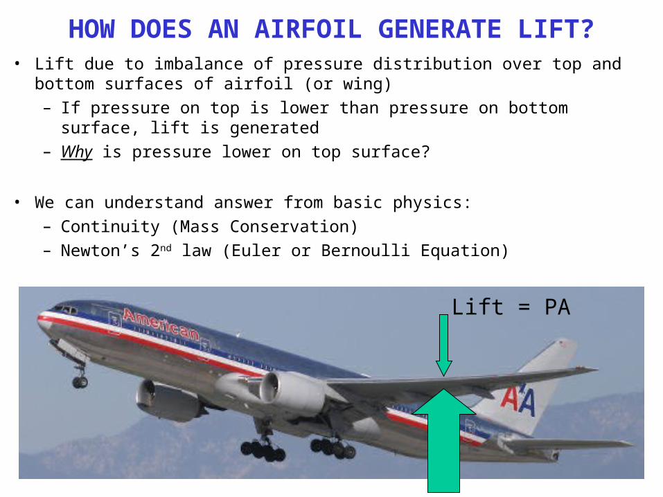
HOW DOES AN AIRFOIL GENERATE LIFT?• Lift due to imbalance of pressure distribution over top and bottom surfaces of
airfoil (or wing)– If pressure on top is lower than pressure on bottom surface, lift is generated– Why is pressure lower on top surface?
• We can understand answer from basic physics:– Continuity (Mass Conservation)– Newton’s 2nd law (Euler or Bernoulli Equation)
Lift = PA
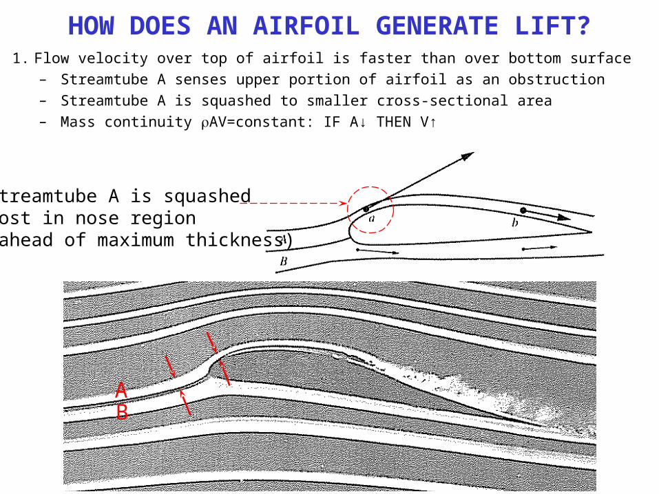
HOW DOES AN AIRFOIL GENERATE LIFT?1. Flow velocity over top of airfoil is faster than over bottom surface
– Streamtube A senses upper portion of airfoil as an obstruction– Streamtube A is squashed to smaller cross-sectional area– Mass continuity AV=constant: IF A↓ THEN V↑
Streamtube A is squashedmost in nose region(ahead of maximum thickness)
AB
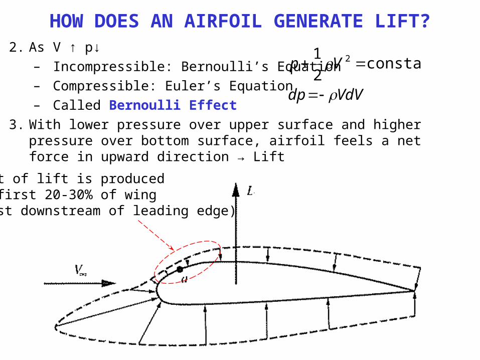
HOW DOES AN AIRFOIL GENERATE LIFT?2. As V ↑ p↓
– Incompressible: Bernoulli’s Equation– Compressible: Euler’s Equation– Called Bernoulli Effect
3. With lower pressure over upper surface and higher pressure over bottom surface, airfoil feels a net force in upward direction → Lift
VdVdp
Vp
constant21 2
Most of lift is producedin first 20-30% of wing(just downstream of leading edge)
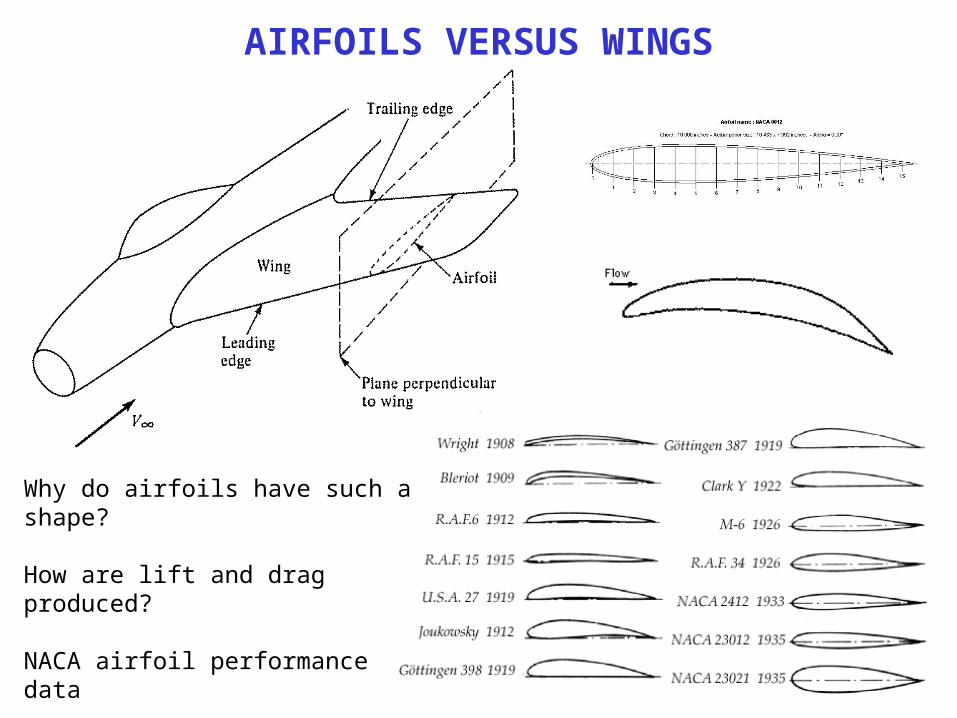
AIRFOILS VERSUS WINGS
Why do airfoils have such a shape?
How are lift and drag produced?
NACA airfoil performance data
How do we design?What is limit of behavior?
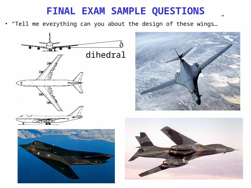
FINAL EXAM SAMPLE QUESTIONS• “Tell me everything can you about the design of these wings…”
dihedral
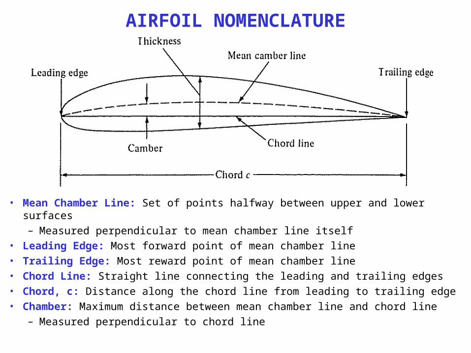
AIRFOIL NOMENCLATURE
• Mean Chamber Line: Set of points halfway between upper and lower surfaces– Measured perpendicular to mean chamber line itself
• Leading Edge: Most forward point of mean chamber line• Trailing Edge: Most reward point of mean chamber line• Chord Line: Straight line connecting the leading and trailing edges• Chord, c: Distance along the chord line from leading to trailing edge• Chamber: Maximum distance between mean chamber line and chord line
– Measured perpendicular to chord line
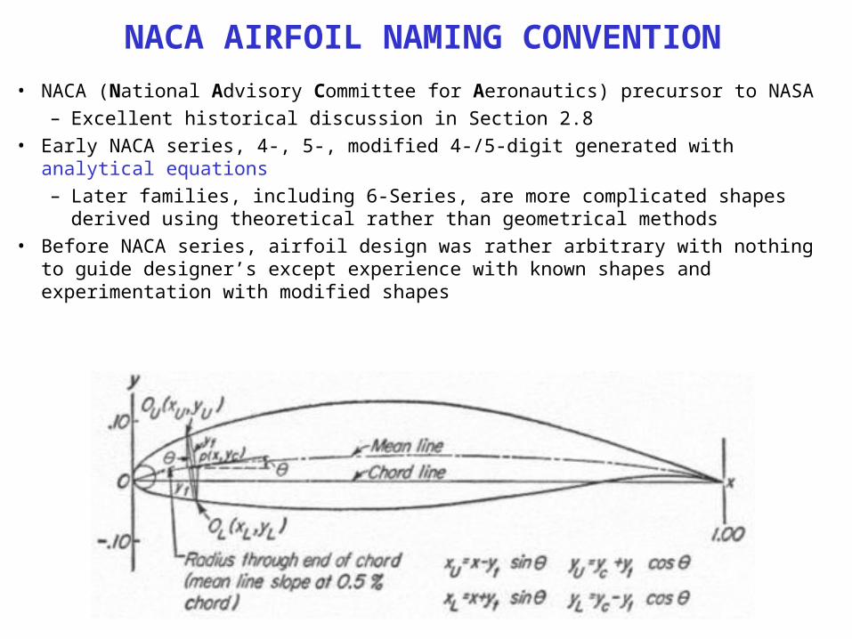
NACA AIRFOIL NAMING CONVENTION• NACA (National Advisory Committee for Aeronautics) precursor to NASA
– Excellent historical discussion in Section 2.8• Early NACA series, 4-, 5-, modified 4-/5-digit generated with analytical equations
– Later families, including 6-Series, are more complicated shapes derived using theoretical rather than geometrical methods
• Before NACA series, airfoil design was rather arbitrary with nothing to guide designer’s except experience with known shapes and experimentation with modified shapes
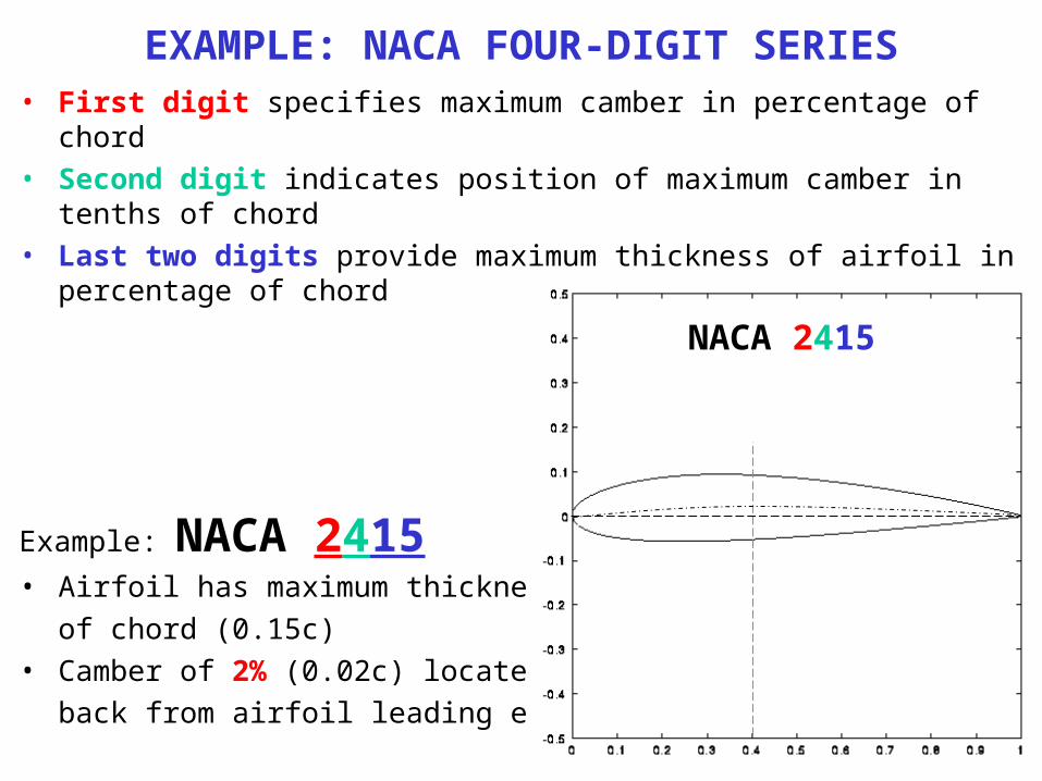
EXAMPLE: NACA FOUR-DIGIT SERIES• First digit specifies maximum camber in percentage of chord• Second digit indicates position of maximum camber in tenths of chord• Last two digits provide maximum thickness of airfoil in percentage of chord
Example: NACA 2415• Airfoil has maximum thickness of 15%
of chord (0.15c)• Camber of 2% (0.02c) located 40%
back from airfoil leading edge (0.4c)
NACA 2415
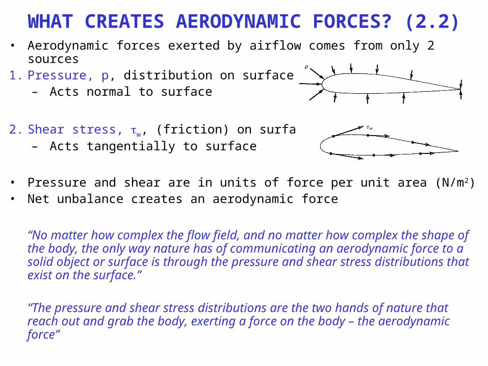
WHAT CREATES AERODYNAMIC FORCES? (2.2)• Aerodynamic forces exerted by airflow comes from only 2 sources1. Pressure, p, distribution on surface
– Acts normal to surface
2. Shear stress, w, (friction) on surface– Acts tangentially to surface
• Pressure and shear are in units of force per unit area (N/m2)• Net unbalance creates an aerodynamic force
“No matter how complex the flow field, and no matter how complex the shape of the body, the only way nature has of communicating an aerodynamic force to a solid object or surface is through the pressure and shear stress distributions that exist on the surface.”
“The pressure and shear stress distributions are the two hands of nature that reach out and grab the body, exerting a force on the body – the aerodynamic force”
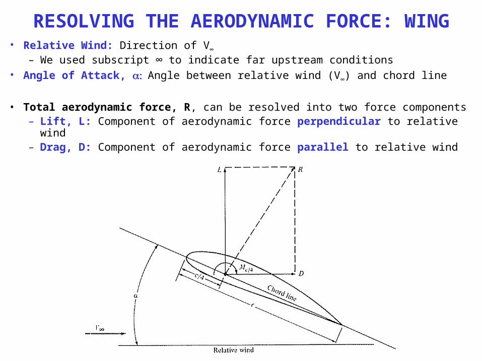
RESOLVING THE AERODYNAMIC FORCE: WING• Relative Wind: Direction of V∞
– We used subscript ∞ to indicate far upstream conditions• Angle of Attack, Angle between relative wind (V∞) and chord line
• Total aerodynamic force, R, can be resolved into two force components– Lift, L: Component of aerodynamic force perpendicular to relative wind– Drag, D: Component of aerodynamic force parallel to relative wind
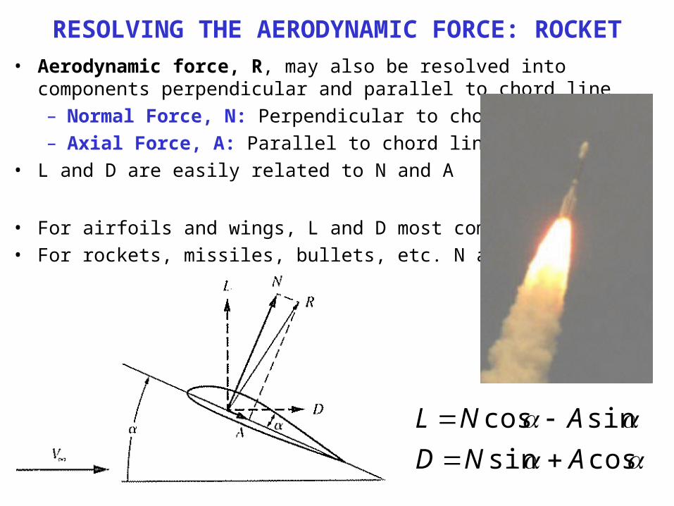
RESOLVING THE AERODYNAMIC FORCE: ROCKET• Aerodynamic force, R, may also be resolved into components perpendicular and
parallel to chord line– Normal Force, N: Perpendicular to chord line– Axial Force, A: Parallel to chord line
• L and D are easily related to N and A
• For airfoils and wings, L and D most common• For rockets, missiles, bullets, etc. N and A more useful
cossinsincos
ANDANL

MORE DEFINITIONS• Total aerodynamic force on airfoil is summation of F1 and F2
• Lift is obtained when F2 > F1
• Misalignment of F1 and F2 creates Moments, M, which tend to rotate airfoil/wing– A moment (torque) is a force times a distance
• Value of induced moment depends on point about which moments are taken– Moments about leading edge, MLE, or quarter-chord point, c/4, Mc/4
– In general MLE ≠ Mc/4
VARIATION OF L, D, AND M WITH • Lift, Drag and M on a airfoil or wing will change as changes
• Variations of these quantities are some of most important information that an airplane designer needs to know
• Aerodynamic Center– Point about which moments essentially do not vary with – Mac=constant (independent of )– For low speed airfoils aerodynamic center is near quarter-chord point

SAMPLE DATA: SYMMETRIC AIRFOIL
Lift
Coe
ffic
ient
Angle of Attack,
A symmetric airfoil generates zero lift at zero
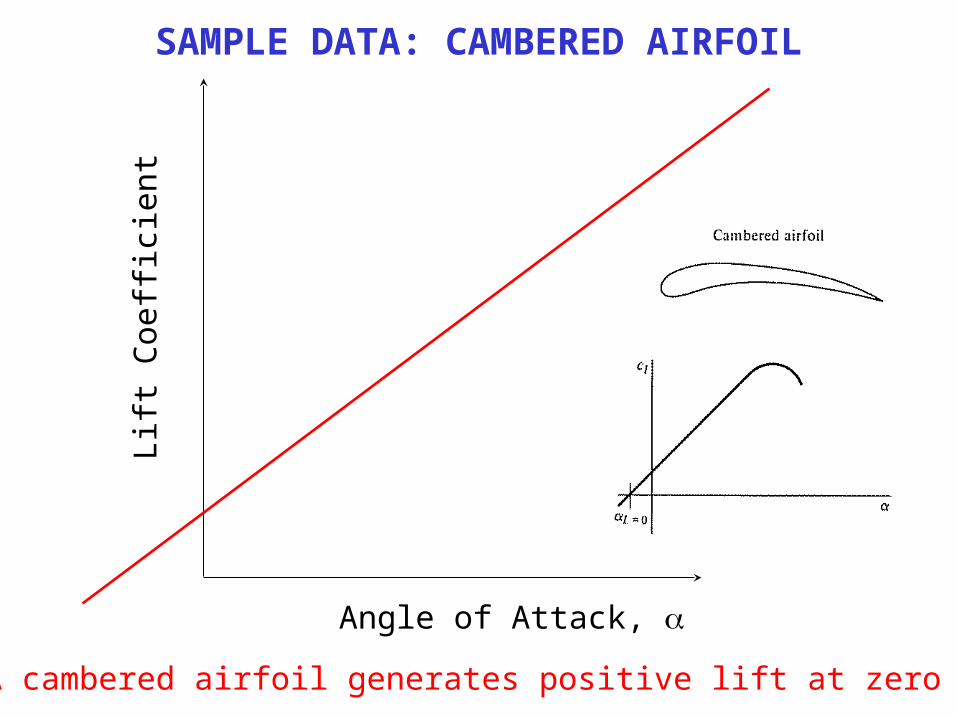
SAMPLE DATA: CAMBERED AIRFOIL
Lift
Coe
ffic
ient
Angle of Attack,
A cambered airfoil generates positive lift at zero

WHY DOES LIFT CURVE BEND OVER?
http://www.soton.ac.uk/Racing/Greenpower/BoundaryLayers/
Low
Moderate
High
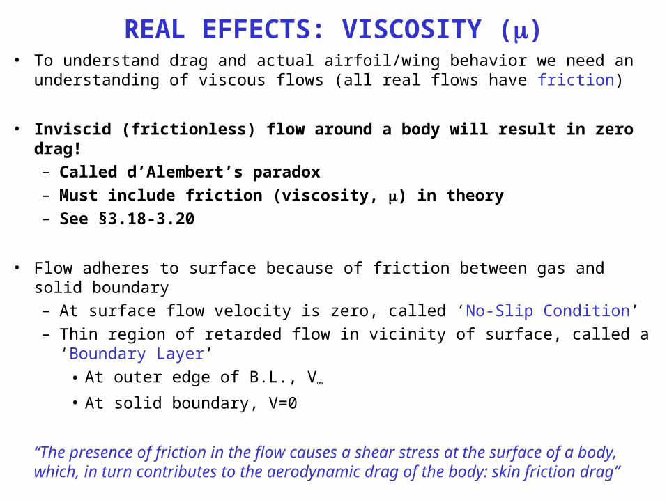
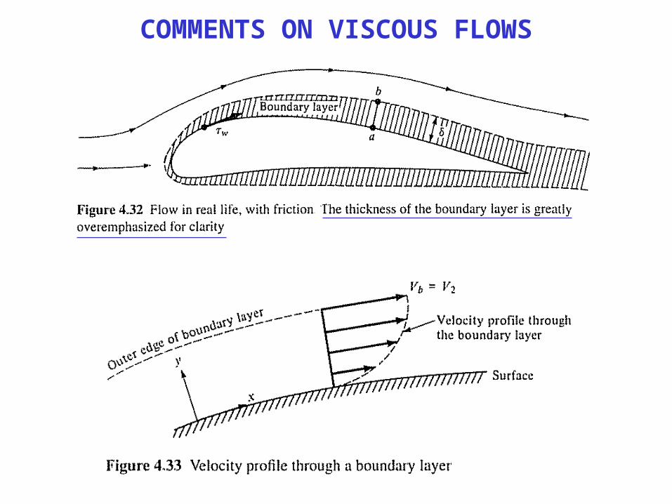
REAL EFFECTS: VISCOSITY ()• To understand drag and actual airfoil/wing behavior we need an understanding of
viscous flows (all real flows have friction)
• Inviscid (frictionless) flow around a body will result in zero drag!– Called d’Alembert’s paradox– Must include friction (viscosity, ) in theory– See §3.18-3.20
• Flow adheres to surface because of friction between gas and solid boundary– At surface flow velocity is zero, called ‘No-Slip Condition’– Thin region of retarded flow in vicinity of surface, called a ‘Boundary Layer’
• At outer edge of B.L., V∞
• At solid boundary, V=0
“The presence of friction in the flow causes a shear stress at the surface of a body, which, in turn contributes to the aerodynamic drag of the body: skin friction drag”
COMMENTS ON VISCOUS FLOWS
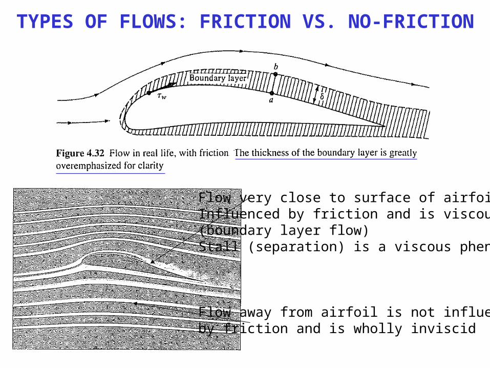
TYPES OF FLOWS: FRICTION VS. NO-FRICTION
Flow very close to surface of airfoil isInfluenced by friction and is viscous(boundary layer flow)Stall (separation) is a viscous phenomena
Flow away from airfoil is not influencedby friction and is wholly inviscid
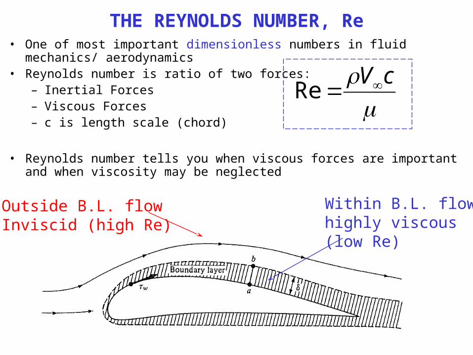
THE REYNOLDS NUMBER, Re• One of most important dimensionless numbers in fluid mechanics/ aerodynamics• Reynolds number is ratio of two forces:
– Inertial Forces– Viscous Forces– c is length scale (chord)
• Reynolds number tells you when viscous forces are important and when viscosity may be neglected
cVRe
Within B.L. flowhighly viscous(low Re)
Outside B.L. flowInviscid (high Re)
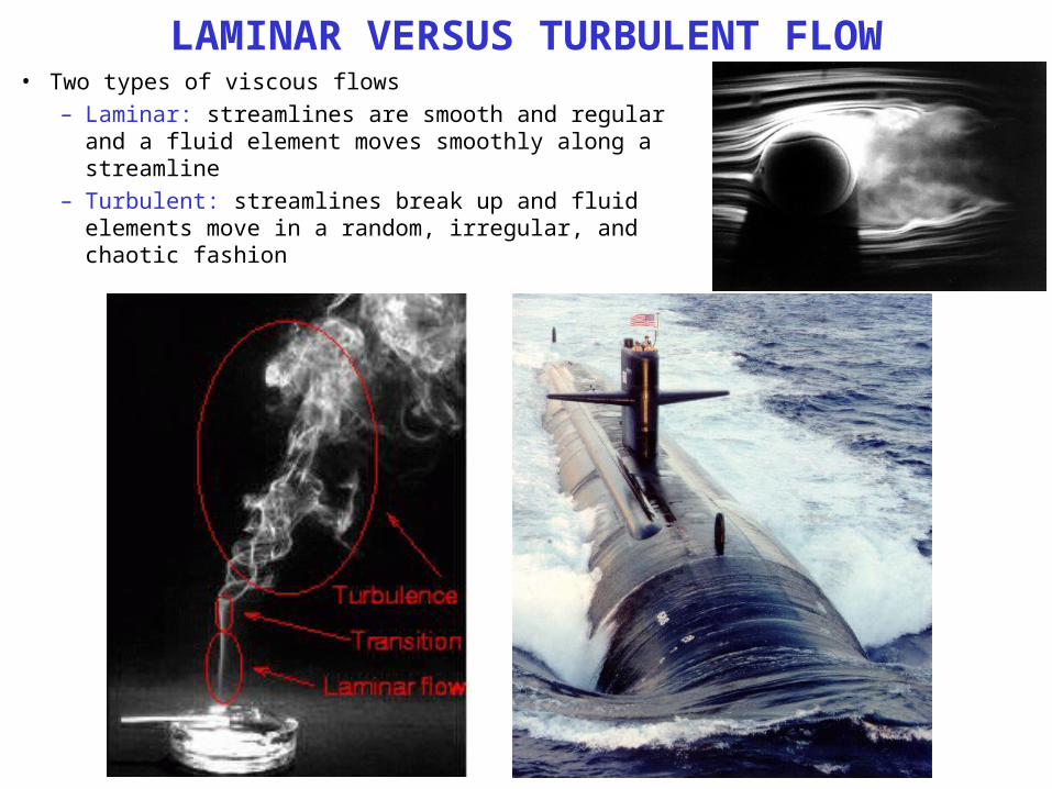
LAMINAR VERSUS TURBULENT FLOW• Two types of viscous flows
– Laminar: streamlines are smooth and regular and a fluid element moves smoothly along a streamline
– Turbulent: streamlines break up and fluid elements move in a random, irregular, and chaotic fashion
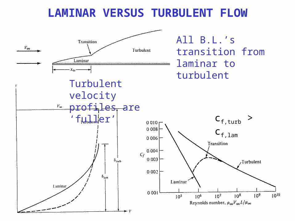
LAMINAR VERSUS TURBULENT FLOW
All B.L.’s transition from laminar to turbulent
cf,turb > cf,lam
Turbulent velocityprofiles are ‘fuller’
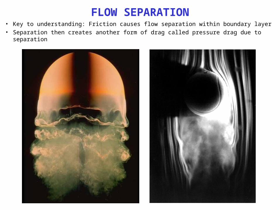
FLOW SEPARATION• Key to understanding: Friction causes flow separation within boundary layer• Separation then creates another form of drag called pressure drag due to separation
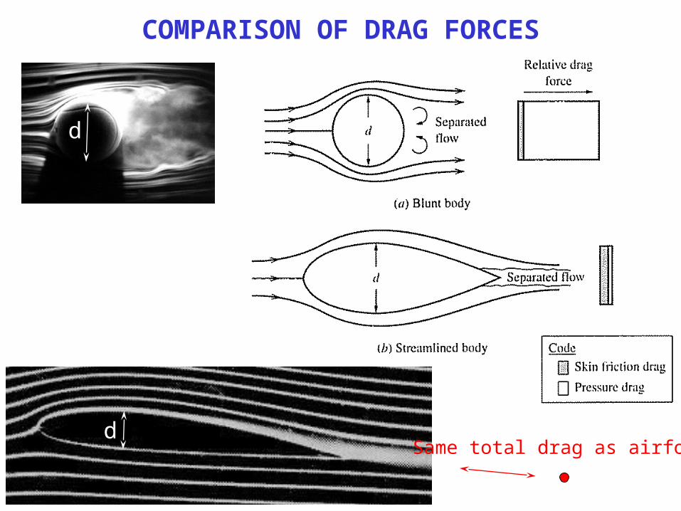
COMPARISON OF DRAG FORCES
d
d
Same total drag as airfoil
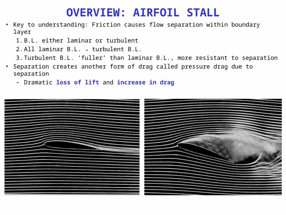
OVERVIEW: AIRFOIL STALL• Key to understanding: Friction causes flow separation within boundary layer
1. B.L. either laminar or turbulent2. All laminar B.L. → turbulent B.L.3. Turbulent B.L. ‘fuller’ than laminar B.L., more resistant to separation
• Separation creates another form of drag called pressure drag due to separation– Dramatic loss of lift and increase in drag
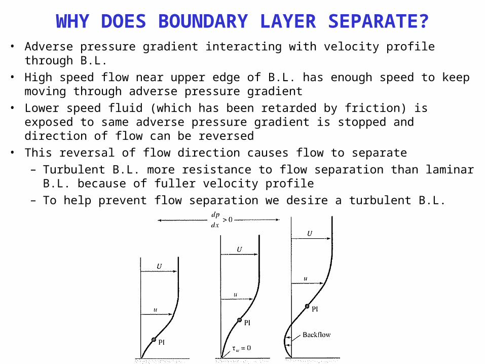
WHY DOES BOUNDARY LAYER SEPARATE?• Adverse pressure gradient interacting with velocity profile through B.L.• High speed flow near upper edge of B.L. has enough speed to keep moving
through adverse pressure gradient• Lower speed fluid (which has been retarded by friction) is exposed to same
adverse pressure gradient is stopped and direction of flow can be reversed• This reversal of flow direction causes flow to separate
– Turbulent B.L. more resistance to flow separation than laminar B.L. because of fuller velocity profile
– To help prevent flow separation we desire a turbulent B.L.
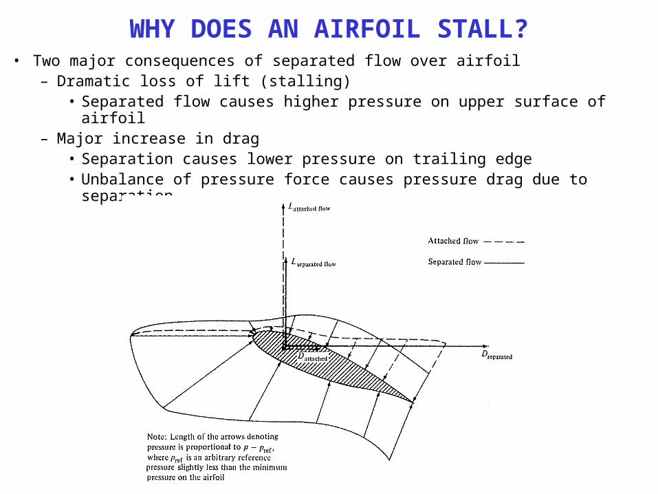
WHY DOES AN AIRFOIL STALL?• Two major consequences of separated flow over airfoil
– Dramatic loss of lift (stalling)• Separated flow causes higher pressure on upper surface of airfoil
– Major increase in drag• Separation causes lower pressure on trailing edge• Unbalance of pressure force causes pressure drag due to separation
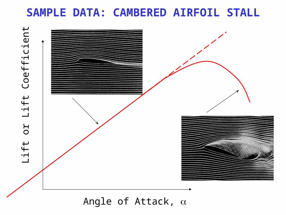
SAMPLE DATA: CAMBERED AIRFOIL STALLLi
ft or
Lift
Coe
ffic
ient
Angle of Attack,
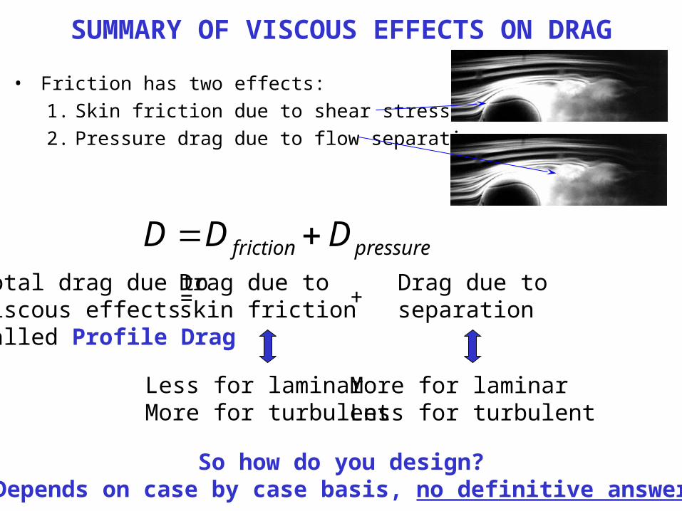
SUMMARY OF VISCOUS EFFECTS ON DRAG
• Friction has two effects:1. Skin friction due to shear stress at wall2. Pressure drag due to flow separation
pressurefriction DDD Total drag due toviscous effectsCalled Profile Drag
Drag due toskin friction
Drag due toseparation= +
Less for laminarMore for turbulent
More for laminarLess for turbulent
So how do you design?Depends on case by case basis, no definitive answer
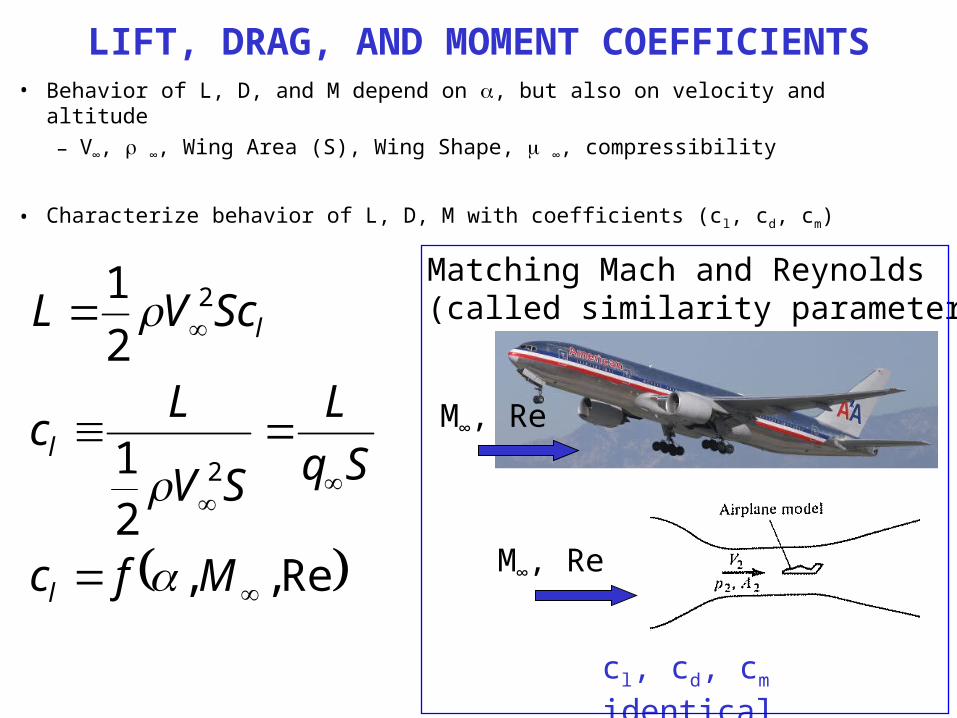
LIFT, DRAG, AND MOMENT COEFFICIENTS• Behavior of L, D, and M depend on , but also on velocity and altitude
– V∞, ∞, Wing Area (S), Wing Shape, ∞, compressibility
• Characterize behavior of L, D, M with coefficients (cl, cd, cm)
Re,,21
21
2
2
Mfc
SqL
SV
Lc
ScVL
l
l
l
Matching Mach and Reynolds(called similarity parameters)
M∞, Re
M∞, Re
cl, cd, cm identical
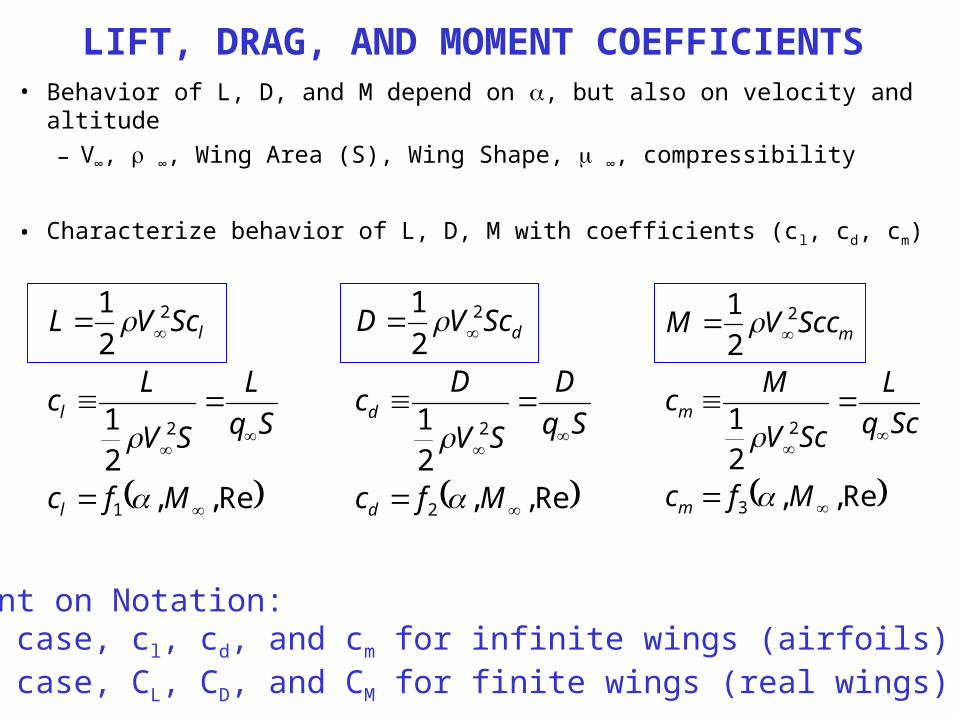
LIFT, DRAG, AND MOMENT COEFFICIENTS• Behavior of L, D, and M depend on , but also on velocity and altitude
– V∞, ∞, Wing Area (S), Wing Shape, ∞, compressibility
• Characterize behavior of L, D, M with coefficients (cl, cd, cm)
Re,,21
21
3
2
2
Mfc
ScqL
ScV
Mc
SccVM
m
m
m
Re,,21
21
2
2
2
Mfc
SqD
SV
Dc
ScVD
d
d
d
Re,,21
21
1
2
2
Mfc
SqL
SV
Lc
ScVL
l
l
l
Comment on Notation:Lower case, cl, cd, and cm for infinite wings (airfoils)Upper case, CL, CD, and CM for finite wings (real wings)
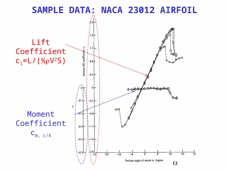
SAMPLE DATA: NACA 23012 AIRFOIL
Lift Coefficientcl=L/(½V2S)
Moment Coefficientcm, c/4
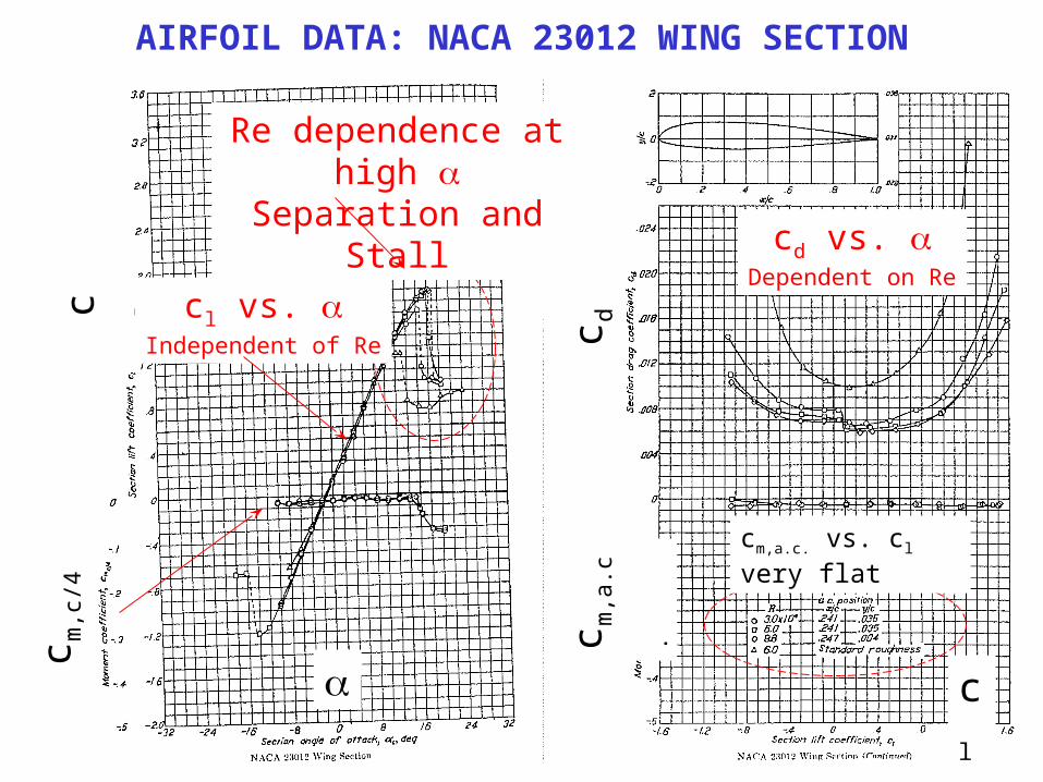
AIRFOIL DATA: NACA 23012 WING SECTIONc l
c m,c
/4
Re dependence at high Separation and Stall
cl
c dc m
,a.c
.
cl vs. Independent of Re
cd vs. Dependent on Re
cm,a.c. vs. cl very flat
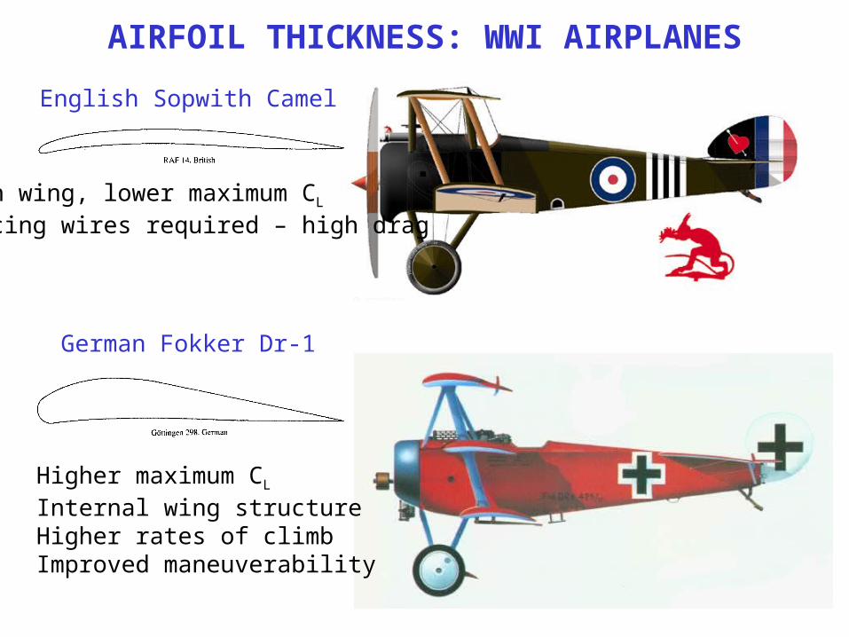
AIRFOIL THICKNESS: WWI AIRPLANES
English Sopwith Camel
German Fokker Dr-1
Higher maximum CL
Internal wing structureHigher rates of climbImproved maneuverability
Thin wing, lower maximum CL
Bracing wires required – high drag
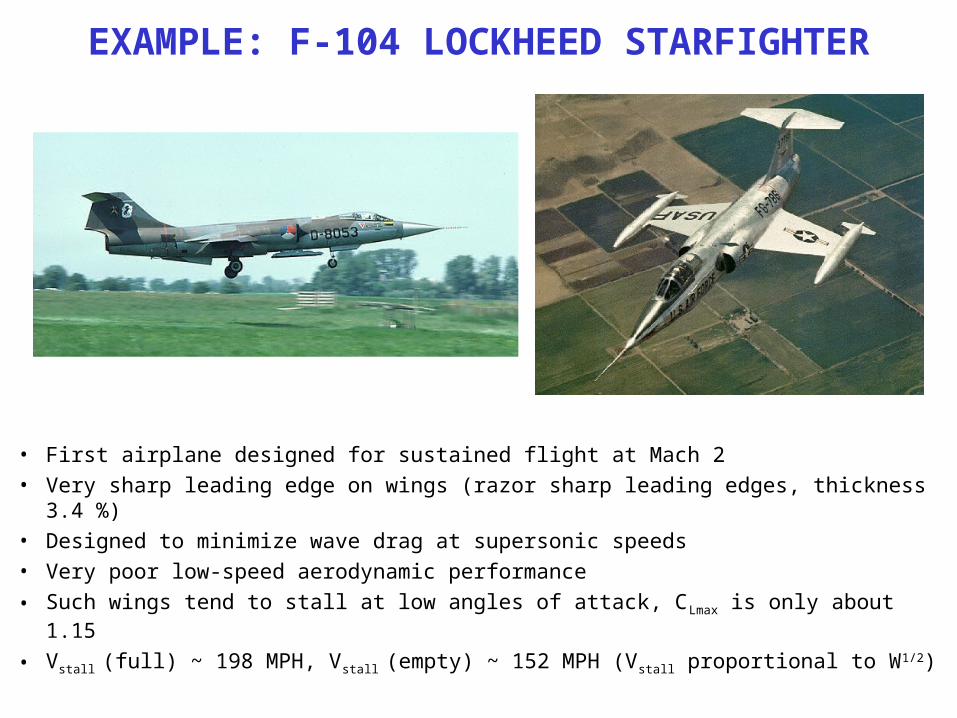
EXAMPLE: F-104 LOCKHEED STARFIGHTER
• First airplane designed for sustained flight at Mach 2• Very sharp leading edge on wings (razor sharp leading edges, thickness 3.4 %)• Designed to minimize wave drag at supersonic speeds• Very poor low-speed aerodynamic performance• Such wings tend to stall at low angles of attack, CLmax is only about 1.15
• Vstall (full) ~ 198 MPH, Vstall (empty) ~ 152 MPH (Vstall proportional to W1/2)
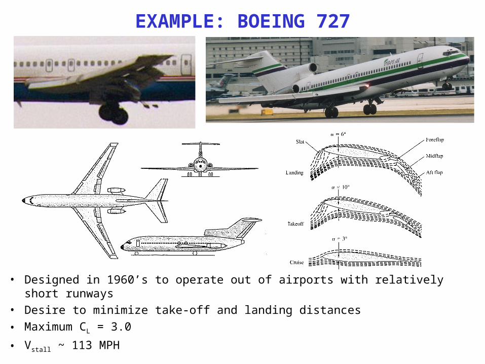
EXAMPLE: BOEING 727
• Designed in 1960’s to operate out of airports with relatively short runways• Desire to minimize take-off and landing distances• Maximum CL = 3.0
• Vstall ~ 113 MPH
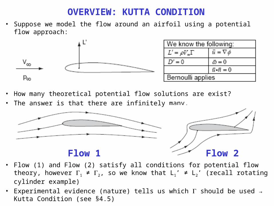
OVERVIEW: KUTTA CONDITION• Suppose we model the flow around an airfoil using a potential flow approach:
• How many theoretical potential flow solutions are exist?• The answer is that there are infinitely many.
• Flow (1) and Flow (2) satisfy all conditions for potential flow theory, however 1 ≠ 2, so we know that L1’ ≠ L2’ (recall rotating cylinder example)
• Experimental evidence (nature) tells us which should be used → Kutta Condition (see §4.5)
Flow 1 Flow 2
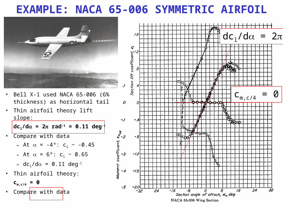
EXAMPLE: NACA 65-006 SYMMETRIC AIRFOIL
• Bell X-1 used NACA 65-006 (6% thickness) as horizontal tail
• Thin airfoil theory lift slope:dcl/d = 2 rad-1 = 0.11 deg-1
• Compare with data– At = -4º: cl ~ -0.45
– At = 6º: cl ~ 0.65
– dcl/d = 0.11 deg-1
• Thin airfoil theory:cm,c/4 = 0
• Compare with data
dcl/d = 2
cm,c/4 = 0
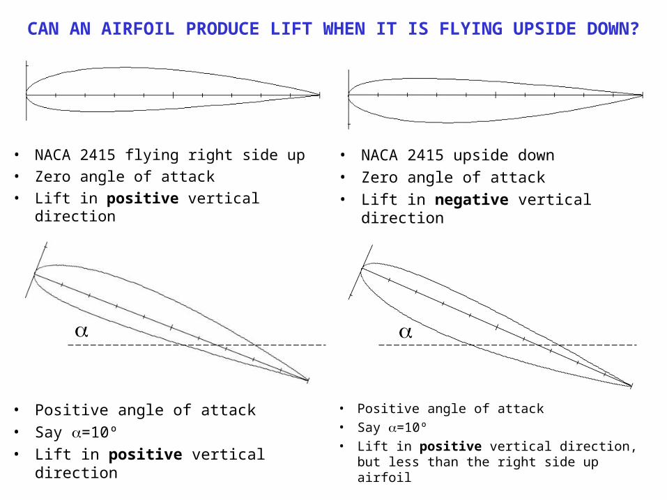
CAN AN AIRFOIL PRODUCE LIFT WHEN IT IS FLYING UPSIDE DOWN?
• NACA 2415 flying right side up• Zero angle of attack• Lift in positive vertical direction
• NACA 2415 upside down• Zero angle of attack• Lift in negative vertical direction
• Positive angle of attack• Say =10º• Lift in positive vertical direction
• Positive angle of attack• Say =10º• Lift in positive vertical direction, but less
than the right side up airfoil
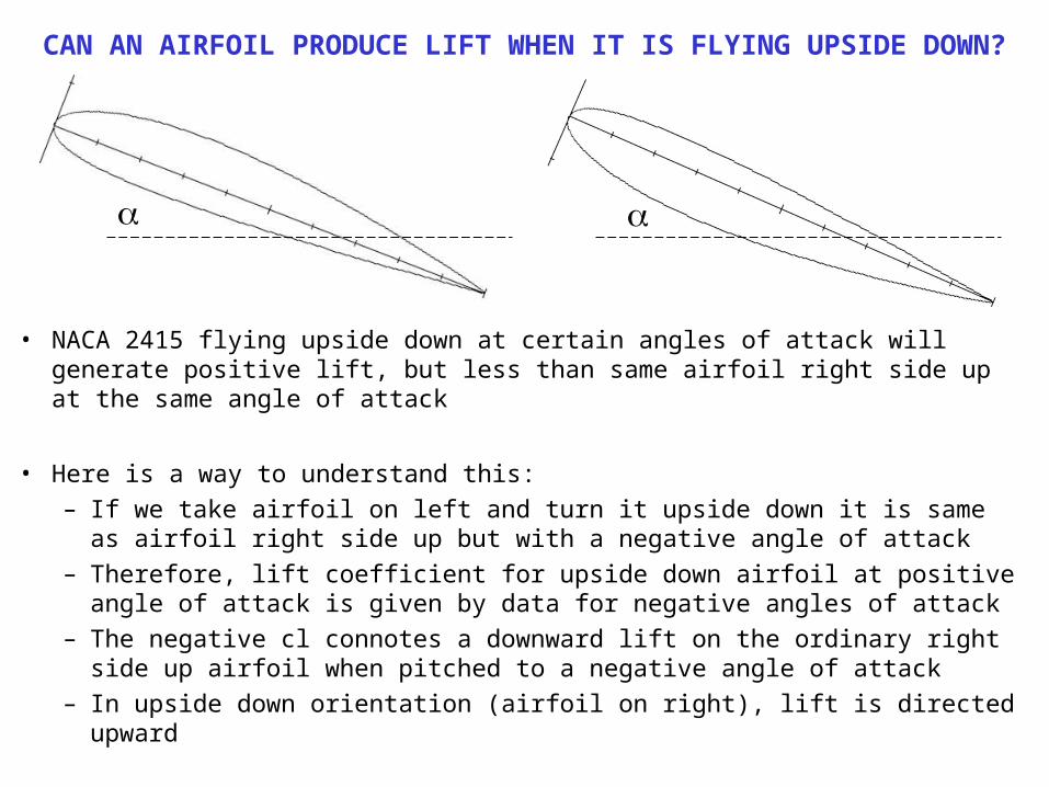
CAN AN AIRFOIL PRODUCE LIFT WHEN IT IS FLYING UPSIDE DOWN?
• NACA 2415 flying upside down at certain angles of attack will generate positive lift, but less than same airfoil right side up at the same angle of attack
• Here is a way to understand this:– If we take airfoil on left and turn it upside down it is same as airfoil right side
up but with a negative angle of attack– Therefore, lift coefficient for upside down airfoil at positive angle of attack is
given by data for negative angles of attack– The negative cl connotes a downward lift on the ordinary right side up airfoil
when pitched to a negative angle of attack– In upside down orientation (airfoil on right), lift is directed upward
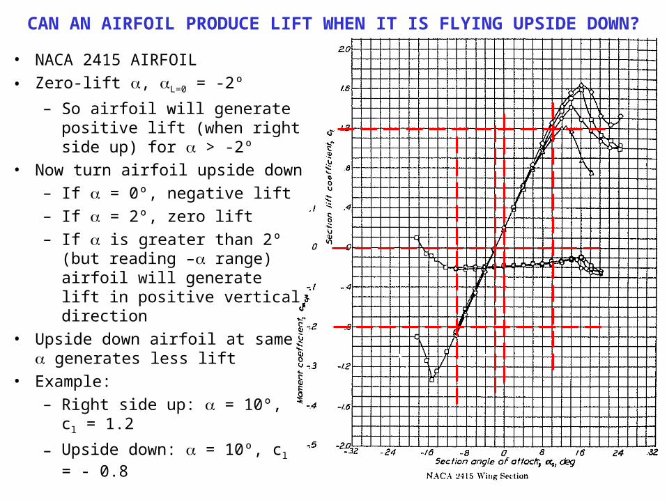
CAN AN AIRFOIL PRODUCE LIFT WHEN IT IS FLYING UPSIDE DOWN?
• NACA 2415 AIRFOIL• Zero-lift , L=0 = -2º
– So airfoil will generate positive lift (when right side up) for > -2º
• Now turn airfoil upside down– If = 0º, negative lift– If = 2º, zero lift– If is greater than 2º (but
reading – range) airfoil will generate lift in positive vertical direction
• Upside down airfoil at same generates less lift
• Example:– Right side up: = 10º, cl = 1.2
– Upside down: = 10º, cl = - 0.8
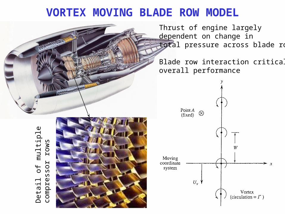
VORTEX MOVING BLADE ROW MODELThrust of engine largelydependent on change intotal pressure across blade rows
Blade row interaction critical tooverall performance
Det
ail o
f mul
tiple
com
pres
sor r
ows

FLIGHT MECHANICS EXAMPLE: GOSSAMER CONDOR
• August 26, 1977: Gossamer Condor, designed by Dr. Paul MacCready (Caltech graduate) in United States and piloted by racing cyclist Bryan Allen, wins £50,000 Kremer prize for first 1 mile figure-of-eight flight by a human-powered aircraft
• Wingspan, b ~ 29 m, average chord, c ~ 2.3 m, total mass ~ 95 kg, CD ~ 0.05• Pilot delivered ¼ HP to propel aircraft• For cruise at sea-level, estimate:
1. Cruise speed attained2. CL
3. HP required input by pilot to achieve a speed of 20 MPH