32.three dimensional analysis of piled-raft foundation in clay soils
TRANSCRIPT
8/11/2019 32.Three Dimensional Analysis of Piled-Raft Foundation in Clay Soils
http://slidepdf.com/reader/full/32three-dimensional-analysis-of-piled-raft-foundation-in-clay-soils 1/12
Three Dimensional Analysis of Piled Raft Foundation in Clay Soils
Sangseom Jeong1* ・ Jaeyeon Cho2
1 Professor, School of Civil and Environmental Engineering, Yonsei University, Seoul 120 749, Korea
2Graduate student, School of Civil and Environmental Engineering, Yonsei University, Seoul 120 749, Korea
❚ Abstract❚
The settlement behavior of a square piled raft in clay soil was investigated using numerical analysis. The emphasis
was on quantifying the reduction of the average and differential settlements in soft and stiff clay soils. To obtain the
detailed information on the piled raft, nonlinear three dimensional finite element analyses with pile-soil slip interface
model were performed for various pile positions, pile numbers, pile lengths under the raft and different loading types.
Based on the results obtained, design considerations concerning the settlement of piled rafts subjected to vertical loading
are discussed. It is found that the variation of reduction ratio of soft clay was relatively greater than that of stiff clay,
whereas the reduction ratio of soft clay was relatively smaller than that of stiff clays. It is also found that the required
pile group-raft area ratio for minimizing differential settlement in soft clay was slightly larger than that of stiff clay
in the same pile array.
Keywords : Piled raft, Average and differential settlement, Three dimensional finite element analysis, Pile-soil slip
interface
*Corresponding author to Sangseom Jeong, Professor, School
of Civil and Environmental Engineering, Yonsei University,
Seoul 120 749, KoreaTel : +82-2-2123-2807, Fax : +82-2-364-5300
E-mail : [email protected]
Received 25 January 2012; Accepted 12 March 2012
International Journal of Geo-Engineering 4(1) : 11-22 (2012)
1. INTRODUCTION
In South Korea, a number of large projects involving
land reclamation are being undertaken. An increasing
number of structures are constructed on soft ground, and
the application of piled rafts on soft ground is becoming
an important issue in foundation design. However, it is
known for an unfavorable foundation type in soft clay,
which may be associated with excessive settlement andinsufficient bearing capacity (Cooke, 1986; Lee et al. 2010;
Poulos, 2001, 2005). Despite these concerns, a few successful
applications of piled rafts on soft clay have been reported
(Kakurai et al. 1987; Poulos, 2005; Tan et al. 2006;
Yamashita et al. 1998).
A piled raft comprises three elements of pile, raft and
subsoil. And the behavior of a piled raft is affected by
the 3D interaction between the subsoil, piles and raft. In
addition, for soft clay conditions, the magnitude of settlement
is larger than for stiff clay conditions under the same vertical
applied load, so soil-structure (piles and raft) interaction
is much more complicated. In this case, a contribution
of the raft, which is contact with soil, is considered and
the loads are carried by the raft and the piles. However,
the piles are usually required to reduce the average and/ordifferential settlements of the foundation to an acceptable
level rather than to carry the major portion of the load.
Therefore, a major design concept is that the settlement
of foundation is permitted within serviceability criterion.
This has affected how piles are designed optimally to reduce
the settlements of the foundation. There are several design
approaches available for predicting the settlement behavior
of piled raft in clay soils subject to vertical loading, using
numerical methods (de Sanctis et al. 2002; Horikoshi and
Randolph, 1997; Katzenbach et al. 2005; Poulos, 1994;Prakoso and Kulhawy, 2001; Randoph, 2003; Reul and
Randolph, 2004). It is recognized, however, that the three
11

8/11/2019 32.Three Dimensional Analysis of Piled-Raft Foundation in Clay Soils
http://slidepdf.com/reader/full/32three-dimensional-analysis-of-piled-raft-foundation-in-clay-soils 2/12
12 Sangseom Jeong and Jaeyeon Cho
(a) (b)
Fig. 1. Representative finite element mesh used in the analysis (ex. 3x3 array, Lp=16 m): (a) Typical 3D FE mesh and boundary
condition; (b) Side view
Table 1. Summary of pile configurations of numerical analyses conducted
Pile array Pile spacing (s)* Pile length (Lp, m)** Remarks
33 3d, 6d, 9d 8f
, 12f
16f , 20
e1) *d (pile diameter): 0.5 m2) **f: floating; e: end bearing44 3d, 4d, 6d
■ Square raft: width (B) = 10 m, thickness (t) = 1 m
dimensional (3D) Finite Element (FE) analysis is the most
appropriate method (Poulos, 2001); additionally 3D FE
analysis which consider pile-soil slip interface offer a better
estimation of the behavior of piled raft in clay soils (Lee
et al. 2010).Therefore, the overall objective of this study focuses
on investigating the settlement behavior of a piled raft on
clay soils under vertical loading by using 3D FE analysis
considering the pile-soil slip interface model. Furthermore,
the comparison of behavior for relatively stiff soil properties
was also carried out for different pile configurations and
loading types then, the settlement behavior of piled rafts
was investigated.
2. THREE DIMENSIONAL FEM MODELING
2.1 Finite Element Mesh and Boundary Conditions
The behavior of a square piled raft (PR) was investigated
using 3D FE analyses. The FE package ABAQUS was
used. The 3D model included a rigorous treatment of the
soil and piled raft which were represented by 27 noded
2nd
order hexahedral elements. The mesh was assumed
to be resting on a rigid layer, and the vertical boundaries
at the left- and right- hand sides were assumed to be on
rollers to allow downward movement of soil layers. The
pile head was connected to the raft rigidly. Due to symmetry,
a quarter of a whole mesh was used in the 3D analyses.
Since modeling of the entire pile installation process israther complicated, the pile was assumed to be in a stress-
free state at the start of the analysis (Jeong et al. 2004).
The stress change in the soil during pile installation was
therefore not included. A summary of the analyses is
shown in Table 1. Fig. 1 shows a typical 3D FE mesh
used in this analysis. In addition, as a reference for the
behavior of a piled raft, an unpiled raft (UR) was also
analyzed.
2.2 Constitutive Modeling
Table 2 summarizes the material parameters used in
the analyses. The soft clay, stiff clay and bearing layer
were modeled with a Mohr-Coulomb model. Attention was
focused on the drained response of a piled raft resting
on a soft and stiff clay layer, so that the soil layer was
idealized using drained properties with the groundwater
table located on the top of the clay layer, assuming a
hydrostatic water pressure distribution. Thus, consolidation
8/11/2019 32.Three Dimensional Analysis of Piled-Raft Foundation in Clay Soils
http://slidepdf.com/reader/full/32three-dimensional-analysis-of-piled-raft-foundation-in-clay-soils 3/12
Three Dimensional Analysis of Piled Raft Foundation in Clay Soils 13
Table 2. Material parameters used in the analyses
Model E ' (MPa) c' (kPa) ' (°) ν' K 0 t (kN/m3)
PileElastic
12,500 - - 0.25 0.01 25
Raft 30,000 - - 0.2 0 25
Clay (soft)Mohr-
Coulomb
5 3 20 0.3 0.65 18
Clay (stiff) 45 20 20 0.3 0.65 19
Bearing 500 0.1 45 0.3 0.5 20
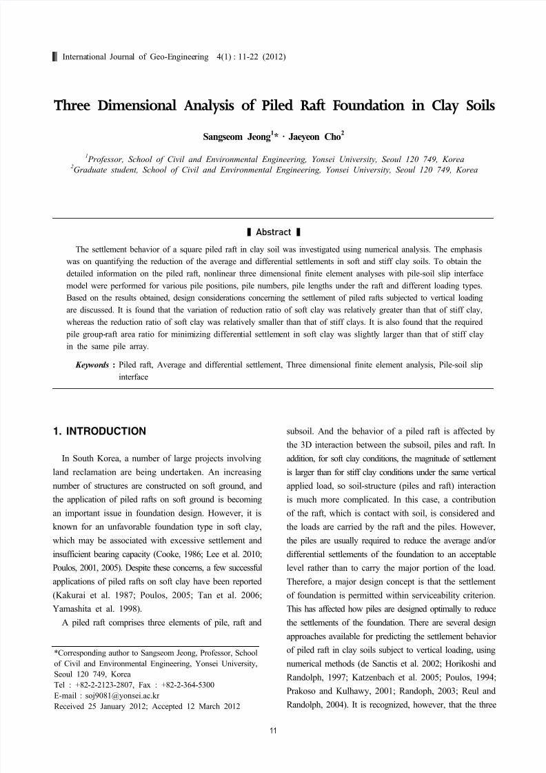
Fig. 2. Behavior at the interface
Fig. 3. Coulomb’s friction laweffects were neglected. Also, to simplify the analysis
process, constant material parameters were adopted for
the soil layer. The raft and piles were modeled with an
isotropic elastic element. The pile was selected as a typical
steel pipe pile which was modeled with a solid section.
The Young’s modulus of the solid pile section was chosen
so that the axial stiffness would be equivalent to that of
a steel pipe pile. The material properties were adopted
from reference values as reported by Lee et al. (2010).
A slip model was used to describe the pile-soil interface
behavior. This model was selected from the contact model
of ABAQUS and the interface modeling was carried out
by specifying a limiting shear displacement of 5 mm (Lee
et al. 2002) and an interface friction coefficient μ=0.3
(Jeong et al. 2004). The raft-soil interface was considered
smooth with contact only. The schematic diagram is shown
in Fig. 2. The interface elements were composed of 2D
quadratic 18-node elements, each element of two nine-node
surfaces compatible with the adjacent solid elements (the
two surfaces coincide initially). In case of “no sliding”
occurred, nodes at the interface have identical coordinates
and the distance between the two surfaces is zero, through
the surfaces, shear stress was transferred as well as normal
forces when two surfaces are attached each other. In the
case that pile element moves along the surface, shear
stress (τ) occurs in the interface. The frictional constitutive
model for interface used is a Coulomb’s frictional model
which is shown in Fig. 3. The shear behavior in the
interface is that elastic behavior occurs until critical shear
stress (τcrit ) in Eq. (1) reached and after that only shear
displacement increases without increase of shear stress.
pcrit ⋅= µ τ (1)
After initial equilibrium, the vertical uniformly distributed
loading (P) was applied on the top of the raft. In this
analysis, the pile installation effect and the settlement due
to the weight of the raft were not considered.
2.3 Post Analysis
The vertical settlements from the 3D FE analyses were
used directly, and the average settlement ( savg ) was calculated
by Eq. (2) (Reul and Randolph, 2004).
3/)2( corner center avg s s s += (2)
where scenter = settlement of raft center, scorner = settlement
of raft corner.
The center to corner differential settlement was calculated
based on Eq. (3).
corner center cc s s s −=∆ − (3)

8/11/2019 32.Three Dimensional Analysis of Piled-Raft Foundation in Clay Soils
http://slidepdf.com/reader/full/32three-dimensional-analysis-of-piled-raft-foundation-in-clay-soils 4/12
14 Sangseom Jeong and Jaeyeon Cho
(a) (b)
(c) (d)
Fig. 4. Typical Finite element mesh: (a) 3D FE mesh; (b) Plan view; (c) Profile view of Torhaus Der Messe; (d) Side view
The rectangular raft-soil stiffness ratio ( K rs) was calculated
at 31.7, using Eq. (4), which can be assumed to represent
a relatively rigid raft because Horikoshi and Randolph
(1997) reported K rs of 0.001 is fully flexible, while K rs
of 1000 is essentially rigid.
35.0
2
2
1
157.5 ⎟
⎠
⎞⎜⎝
⎛ ⎟ ⎠
⎞⎜⎝
⎛
−
−=
L
t
L
B
E
E K r
r
s
s
r rs
ν
ν
(4)
where E r and E s = Young’s modulus of the raft and the
soil, ν r and ν s = Poisson’s ratio of the raft and the soil
respectively, t r = thickness of the raft, B and L = breadth
and the length of the rectangular raft, respectively.
The piled raft coefficient described the ratio of the sum
of all pile load (R pile) to the total load of the foundation
(R tot) using Eq. (5).
tot
pile pr
R
RΣ=α
(5)
2.4 Validation
The validation of the 3D FE model was examined by a
comparison of the analyzed results with the field measure-
ment for vertically loaded piled rafts on the Frankfurt
clay, which was carried out by Sommer (1991). A total
number of 84 bored piles with a length of 20 m and
diameter of 0.9 m were located under two 17.5 m × 24.5
m large rafts with 2.5 m thickness. Fig. 4 (a) shows a
8/11/2019 32.Three Dimensional Analysis of Piled-Raft Foundation in Clay Soils
http://slidepdf.com/reader/full/32three-dimensional-analysis-of-piled-raft-foundation-in-clay-soils 5/12
Three Dimensional Analysis of Piled Raft Foundation in Clay Soils 15
Table 3. Material properties used for 3D FE analysis
Clay Sand Raft Piles
Young’s modulus, E’: MPa 47 75 34000 23500
Poisson’s ratio, ν’ 0.15 0.25 0.2 0.2
Total unit weight, : kN/m3 19 18 15 15
Angle of internal friction, ’ 20 32.5 - -
Cohesion, c’: kPa 20 0 - -
Table 4. Comparison of the results
Results scenter (mm) Piled raft coefficient (pr)
Measured (Sommer, 1991) 124 0.67
Reul & Randolph (2003) 96 0.76
Present study
(Frankfurt clay)
Slip analysis 114 0.65
No-slip analysis 92 0.81
Present study
(Soft clay)
Slip analysis 743* 0.96
No-slip analysis 640* 1.0
Scenter* =Max. Settlement
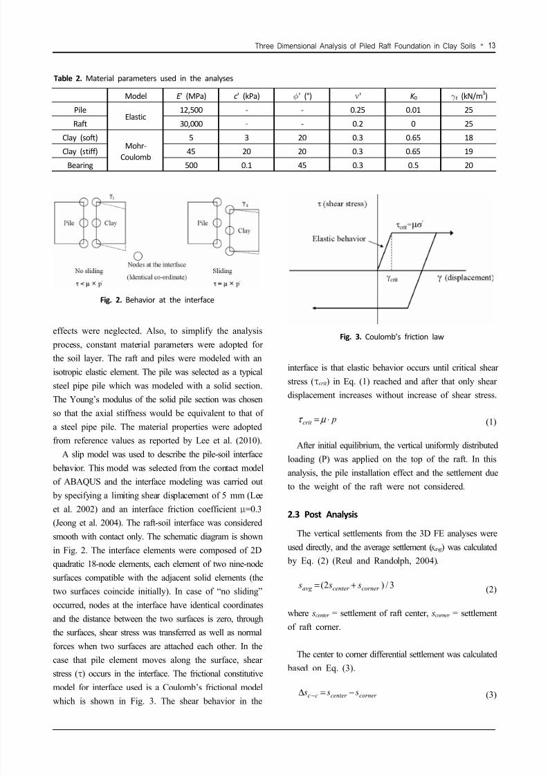
Fig. 5. Calculated load-settlement curve
3D FE mesh used in this analysis. The subsoil comprises
quaternary sand up to 2.5 m below the bottom of the raft,
followed by the Frankfurt clay. The material properties
of the soil and piled raft, which were adopted from the
values as reported by Reul & Randolph (2004), are shown
in Table 3. And the constant (average) values of the drainedYoung’s modulus and drained shear strength parameters
were adopted to simplify the analysis for the soil layer.
The interface friction coefficient was estimated from the
soil friction angle using Eq. (6) and (7). Therefore, the
interface friction coefficient of 0.3 was used. An applied
load of 200 MN for each raft (Sommer, 1991) was applied
as a uniform load over the whole raft area.
0
)tan(
K
β δ µ ==
(6)
where δ is interface angle and K 0 is an earth pressure
coefficient at rest.
))sin1(/cos(sintan 21 φ φ φ δ +×= −
(7)
where is soil friction angle.
For this case, the comparative results of 3D FE analysis
and field measurements are shown in Fig. 5. In addition,
the 3D FE analysis result reported by Reul and Randolph
(2004) and relatively soft soil properties were compared. The
calculated and measured center settlements were summarized
in Table 4. All values of 3D FE analyses are smaller than
the measured one. However, there was reasonably good
agreement between the result of 3D FE model with an
interface and that from the measured. In addition, the
trends of results of no-slip analysis were similar to those
obtained by the thin-layer interface analysis of Reul and
Randolph (2004). For a soft clay on the piled raft, the
settlement of the raft was larger than that of a Frankfurt
clay (=stiff clay), and the piled raft coefficient (α pr ) was
significantly affected by soil properties. The coefficient

8/11/2019 32.Three Dimensional Analysis of Piled-Raft Foundation in Clay Soils
http://slidepdf.com/reader/full/32three-dimensional-analysis-of-piled-raft-foundation-in-clay-soils 6/12
16 Sangseom Jeong and Jaeyeon Cho
(a) 3x3, s=3d (b) 3x3, s=9d
(c) 4x4, s=3d (d) 4x4, s=6d
Fig. 6. Effect of loading types on load-average settlement curves for soft clay
value was mostly higher for soft clay than for stiff clay.
And the non-slip analysis was also higher than the value
from the slip analysis. This difference in the piled raft
coefficient was caused by the contribution of the raft,
which was more efficient with stiff clay (Lee et al. 2010).
3. RESULTS AND DISCUSSION
3.1 Effect of Loading Types
Fig. 6 and Fig. 7 show general load-average settlement
curves of piled raft with various pile configurations and
different raft-soil stiffness ratio under uniform and point
loading. The raft on stiff clay (K rs = 3.5) was relatively
more flexible than that for soft clay (K rs = 31.7). The
pile lengths (L p) ranged from zero (UR) to 20 m (end
bearing). By comparing the load-settlement curves of the
uniform loading and point loading, the behaviors of load-
settlement were similar and the effects of the different
loading types on the average settlements were insignificant
in soft clay. For stiff clay, the average settlement for
point loading was larger than for uniform loading, but
the difference became very small and an effect of loading
type could be negligible. This was similar to results
reported by Poulos (2001).
Fig. 8 and Fig. 9 show a load-center to corner differential
settlement curves. In contrast with average settlements,the load-differential settlement behavior was affected by
not only pile configuration but also loading type. For point
loading, the settlement profiles appeared concave and the
settlement increased with increasing load level. For uniform
loading, according to pile configurations, the deformed shape
of the raft was changed according to pile configurations.
3.2 Average Settlements
Fig. 10 shows the typical load-normalized average settle-
ment curves of a piled raft and an unpiled raft. Additionally,
The ultimate bearing capacity of a square unpiled raft
(QUR_ult), which was used to normalize the applied load
level (P/QUR_ult), was estimated by the load of settlement
of 10% B (Cooke, 1986; de Sanctis and Mandolini, 2003,
2006) from the ABAQUS analysis of the unpiled raft
load-settlement relationships reported by Lee (2007). The

8/11/2019 32.Three Dimensional Analysis of Piled-Raft Foundation in Clay Soils
http://slidepdf.com/reader/full/32three-dimensional-analysis-of-piled-raft-foundation-in-clay-soils 7/12
Three Dimensional Analysis of Piled Raft Foundation in Clay Soils 17
(a) 3x3, s=3d (b) 3x3, s=9d
(c) 4x4, s=3d (d) 4x4, s=6d
Fig. 7. Effect of loading types on load-average settlement curves for stiff clay
(a) 3x3 3d (b) 3x3 9d
(c) 4x4 3d (d) 4x4 6d
Fig. 8. Effect of loading types on load-differential settlement curves for soft clay
8/11/2019 32.Three Dimensional Analysis of Piled-Raft Foundation in Clay Soils
http://slidepdf.com/reader/full/32three-dimensional-analysis-of-piled-raft-foundation-in-clay-soils 8/12
18 Sangseom Jeong and Jaeyeon Cho
(a) 3x3 3d (b) 3x3 9d
(c) 4x4 3d (d) 4x4 6d
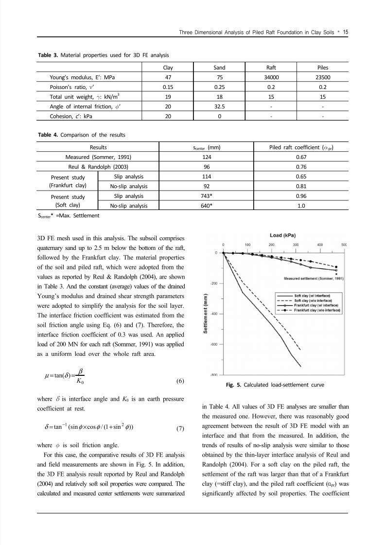
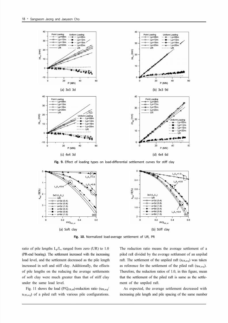
Fig. 9. Effect of loading types on load-differential settlement curves for stiff clay
(a) Soft clay (b) Stiff clay
Fig. 10. Normalized load-average settlement of UR, PR
ratio of pile lengths L p/Ls ranged from zero (UR) to 1.0
(PR-end bearing). The settlement increased with the increasing
load level, and the settlement decreased as the pile length
increased in soft and stiff clay. Additionally, the effects
of pile lengths on the reducing the average settlements
of soft clay were much greater than that of stiff clay
under the same load level.Fig. 11 shows the load (P/QUR,ult)-reduction ratio (sPR,avg/
sUR,avg) of a piled raft with various pile configurations.
The reduction ratio means the average settlement of a
piled raft divided by the average settlement of an unpiled
raft. The settlement of the unpiled raft (sUR,avg) was taken
as reference for the settlement of the piled raft (sPR,avg).
Therefore, the reduction ratios of 1.0, in this figure, mean
that the settlement of the piled raft is same as the settle-
ment of the unpiled raft.As expected, the average settlement decreased with
increasing pile length and pile spacing of the same number

8/11/2019 32.Three Dimensional Analysis of Piled-Raft Foundation in Clay Soils
http://slidepdf.com/reader/full/32three-dimensional-analysis-of-piled-raft-foundation-in-clay-soils 9/12
Three Dimensional Analysis of Piled Raft Foundation in Clay Soils 19
(a) 3×3 array (b) 4×4 array
Fig. 11. Normalized average settlements with load levels of soft clay
(a) 3×3 array (b) 4×4 array
Fig. 12. Normalized average settlements with load levels of stiff clay
of piles. This was due to the fact that, for closely spaced
piles, the bearing capacity of pile groups in a piled raft is
decreased by the group effect. The reduction ratio decreased
until certain inflection points and then increased with
increasing load level, though the actual average settlements
of a piled raft generally increased with the increasing load
levels. These inflection points were estimated bearing capacityof a Single Pile (SP) multiplied by the number of piles
from the ABAQUS analysis of single pile load-settlement
relationships (Lee, 2007). For wide pile spacing (ex. 3×3,
s=9d; 4×4, s=6d), the location of inflection points were
similar to the sum of the ultimate bearing capacity of single
piles. However, for narrow pile spacing, these points were
slightly larger than the sum of the ultimate bearing capacity
of single piles. It was estimated that the behavior of piles
in a piled raft with wide pile spacing was similar to the
behavior of single pile. Likewise, for narrow pile spacing,the yielding point of pile groups in a piled raft was slightly
smaller than that of wide pile spacing cases; this is due to
the effect of block mode of failure of pile groups, though the
bearing capacity of pile groups in piled raft was decreased
by the group effect of pile group. For the cases considered,
the efficiency for reducing average settlement was maximized
when the point was similar to the ultimate capacity of
pile groups in a piled raft.
For stiff clay, as shown in Fig. 12, as soft clay, thereduction ratio decreased with increasing pile length and
pile spacing of the same number of piles. Also, it was
shown that the variation of reduction ratio of soft clay
was relatively greater than that of stiff clay, and the
reduction ratio was relatively smaller than that of stiff
clay, although the real average settlement of soft clay
was larger than that of stiff clay.
The efficiency for reducing average settlement increased
when the point was similar to the ultimate capacity of pile
groups in piled raft and after then, efficiency decreased.The bearing capacity developed by piles within a piled
raft can be significantly greater than that for a pile in
8/11/2019 32.Three Dimensional Analysis of Piled-Raft Foundation in Clay Soils
http://slidepdf.com/reader/full/32three-dimensional-analysis-of-piled-raft-foundation-in-clay-soils 10/12
20 Sangseom Jeong and Jaeyeon Cho
(a) 3×3 array (b) 4×4 array
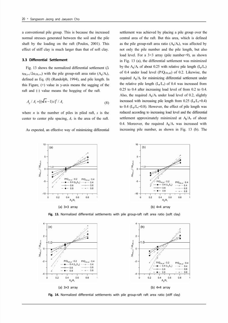
Fig. 13. Normalized differential settlements with pile group-raft raft area ratio (soft clay)
(a) 3×3 array (b) 4×4 array
Fig. 14. Normalized differential settlements with pile group-raft raft area ratio (stiff clay)
a conventional pile group. This is because the increased
normal stresses generated between the soil and the pile
shaft by the loading on the raft (Poulos, 2001). This
effect of stiff clay is much larger than that of soft clay.
3.3 Differential Settlement
Fig. 13 shows the normalized differential settlement (Δ
sPR,c-c/ΔsUR,c-c) with the pile group-raft area ratio (Ag/Ar ),
defined as Eq. (8) (Randolph, 1994), and pile length. In
this Figure, (+) value in y-axis means the sagging of the
raft and (-) value means the hogging of the raft.
r r g A sn A A /])1[(/ 2−= (8)
where n is the number of piles in piled raft, s is thecenter to center pile spacing, Ar is the area of the raft.
As expected, an effective way of minimizing differential
settlement was achieved by placing a pile group over the
central area of the raft. But this area, which is defined
as the pile group-raft area ratio (Ag/Ar ), was affected by
not only the pile number and the pile length, but also
load level. For a 3×3 array (pile number=9), as shownin Fig. 13 (a), the differential settlement was minimized
by the Ag/Ar of about 0.25 with relative pile length (L p/Ls)
of 0.4 under load level (P/QUR,ult) of 0.2. Likewise, the
required Ag/Ar for minimizing differential settlement under
the relative pile length (L p/Ls) of 0.4 was increased from
0.25 to 0.4 after increasing load level of from 0.2 to 0.4.
Also, the required Ag/Ar under load level of 0.2, slightly
increased with increasing pile length from 0.25 (L p/Ls=0.4)
to 0.4 (L p/Ls=0.8). However, the effect of pile length was
reduced according to increasing load level and the differentialsettlement approximately minimized at Ag/Ar of about
0.4. Moreover, the required Ag/Ar was increased with
increasing pile number, as shown in Fig. 13 (b). The

8/11/2019 32.Three Dimensional Analysis of Piled-Raft Foundation in Clay Soils
http://slidepdf.com/reader/full/32three-dimensional-analysis-of-piled-raft-foundation-in-clay-soils 11/12
Three Dimensional Analysis of Piled Raft Foundation in Clay Soils 21
required Ag/Ar of 4×4 arrays was about 0.45, with pile
length of 0.4 under load level of 0.2. In these cases, the
required Ag/Ar increased with increasing load levels from
0.45 to 0.5 (4×4), respectively, after increasing load level
of from 0.2 to 0.4, as well. By contrast with the 3×3 array,however, the pile length had less affected the required
Ag/Ar for minimizing differential settlement under low
load level of 0.2, according to increasing pile number.
The results showed that the required Ag/Ar for minimizing
differential settlement tends to be about 0.25~0.4 parti-
cularly in 3×3 pile groups in piled raft according to pile
length and load level. As pile numbers are increased, the
minimum required Ag/Ar increased to 0.45~0.5 of 4×4
pile group.
For the stiff clay, as shown in Figure 14, similar resultsdeveloped as with soft clay. However, the effect of pile
length was larger than that of soft clay for the required
Ag/Ar of minimizing differential settlement. The differential
settlement could be minimized effectively when the smallest
number of piles (3×3 array) is located below the Ag/Ar
of approximately 0.2 (load level=0.2), 0.35 (load level=0.4).
As same as soft clay, the required Ag/Ar was increased
with increasing pile number, as shown in Fig. 14 (b). The
required Ag/Ar of 4×4 arrays was about 0.3, with pile
length of 0.4 under load level of 0.2.The optimum Ag/Ar was similar in both soil conditions
but the optimum Ag/Ar of soft clay was slightly larger
than stiff clay for low load level and the optimum Ag/Ar
was changed according to load levels. Furthermore, the
optimum Ag/Ar was affected by pile length and piles
numbers. Consequently, an optimum Ag/Ar should accompany
a pile length, numbers and load levels. The required
Ag/Ar for minimizing differential settlement in soft clay
is larger than that of stiff clay and in both cases of soil
condition, the required Ag/Ar for inducing differentialsettlement of unpiled raft (ΔsPR,c-c/ΔsUR,c-c=1.0) was similar
in the same pile array.
Similar studies on required pile geometry in stiff clay
under uniform loading have been reported by Horikoshi
and Randolph (1998), Prakoso and Kulhawy (2001), de
Sanctis et al. (2002). They suggested that the piles of
length greater than about 70% of the width of the raft
are required and they conclude that the piles should be
situated over the central 16-25%, 16-36% and 25-45% of
raft area, respectively. For soft clay, Randolph (2003)
reported that the most significant factors were the short
pile installed extending through that layer over the full
raft area, or longer piles used in the central 25-40% of
the raft area. This is similar to the results of this study.
However, previous studies did not consider the effect of
pile numbers or load level in detail, which they generally
take to be about 0.3. However, as investigated, the requiredAg/Ar should be accompanied a pile length, pile numbers
and load level, in this study.
4. CONCLUSIONS
A series of numerical analysis were conducted to investi-
gate the behavior of a square piled raft subjected to vertical
loading. In this study, the 3D elasto-plastic FE analyses
with slip interface model of pile-soil contact were carried
out with drained shear parameters and no consolidationeffect for a clay layer. Pile positions, pile number, pile
length and load distribution on the raft were varied and
the effects of pile geometries, load levels and loading types
were examined. Based on the results, the validity of the
3D elasto-plastic FE analyses with slip interface model
at the pile-soil contact was evaluated and the settlement
behavior of piled raft was examined. From this study, the
following conclusions can be drawn;
(1) The average settlement could be reduced effectivelywith wider spaced pile groups with the same number
of piles. Furthermore, the efficiency of piles in a piled
raft was maximized when the magnitude of the applied
load of the piled raft was similar to the ultimate
capacity of pile groups in the piled raft. It was shown
that the reduction ratio was relatively smaller than
that of stiff clay, although the real average settlement
of soft clay was larger than that of stiff clay.
(2) The differential settlement of the piled rafts can be
minimized when the central area of the raft is supported by piles. The required (install) area The required install
area of pile group for minimizing differential settlement
was affected by not only the pile number and length,
but also the load level. The required Ag/Ar was generally
increased with increasing load level and pile number,
but the pile length had less influence compared with
the effect of pile number. And the required Ag/Ar for
minimizing differential settlement in soft clay is slightly
larger than that of stiff clay in the same pile array.
(3) The average and differential settlements of the raft
are dependent on the combination of pile geometries;
thus the design of pile geometries should be carefully

8/11/2019 32.Three Dimensional Analysis of Piled-Raft Foundation in Clay Soils
http://slidepdf.com/reader/full/32three-dimensional-analysis-of-piled-raft-foundation-in-clay-soils 12/12
22 Sangseom Jeong and Jaeyeon Cho
considered to satisfy the both settlement criterion. The
loading type (uniform or point load) greatly influences
the differential settlement rather than the average
settlement.
REFERENCES
ABAQUS. (2010). User’s manual. version 6.10. Hibbit, Karlsson &
Sorensen, Pawtucket R.I.
Cooke, R.W. (1986). Piled raft foundations on stiff clays: a
contribution to design philosophy. Geotechnique. 36(2), 169-203.
de Sanctis, L., Mandolini, A., Russo, G. & Viggiani, C. (2002).
Some remarks on the optimum design of piled rafts. Proc.
Deep Foundations 2002: An International Perspective on
Theory, Design, Construction and Performance ASCE. 405-425.
de Sanctis L, Mandolini A. (2003). On the ultimate vertical load
of piled rafts on the soft clay soils. Proc. 4th international geotechnical seminar on deep foundation on bored and auger
piles, Ghent: Millpress. 379-86.
de Sanctis L, Mandolini A. (2006). Bearing capacity of piled rafts
on soft clay soils. J. Geotech. Geoenviron. Eng ASCE. 132(12),
1600-10.
Horikoshi, K. & Randolph, M. F. (1997). On the definition of
raft-soil stiffness ratio. Géotechnique. 47(5), 1055-1061.
Horikoshi, K. & Randolph, M. F. (1998). A contribution to the
optimum design of piled rafts. Géotechnique. 48(2), 301-317.
Jeong, SS., Lee, J. H. & Lee, C. J. (2004). Slip effect at the
pile-soil interface on dragload. Comput. Geotech. 31, 115-126.
Katzenbach, R., Schmitt, A. & Turek, J. (2005). Assessing
settlement of high-rise structures by 3D simulations. Computer-
Aided Civil and Infrastructure Engineering. 20, 221-229.
Kakurai M, Yamashita K, Tomono M. (1987). Settlement behavior
of piled raft foundation on soft ground. In: Proceedings of 8th
ARCSMFE . p. 373-6.
Lee, C. J., Bolton, M. D. & Al-Tabbaa, A. (2002). Numerical
modelling of group effects on the distribution of dragloads in pile
foundations. Géotechnique. 52(5), 325-335.
Lee, J. H. (2007). Nonlinear Three Dimensional Analysis of
Settlement of Piled raft in Clay Soils. Ph.D Thesis, Yonsei
University, South Korea.
Lee, J. H., Kim, YH & Jeong, S.S. (2010). Three-dimensional
analysis of bearing behavior of piled raft on soft clay. Comput.
Geotech. 37, 103-114.
Poulos, H. G. (1994). Alternative design strategies for piled raft
foundations. Proc. 3rd Int. Conf. Deep Foundations, Singapore.
239-244.
Poulos, H. G. (2001). Piled raft foundations: design and applications.
Géotechnique. 51(2), 95-113.
Poulos HG. (2005). Piled raft and compensated piled raft
foundations for soft soil sites. Advances on designing and testing
deep foundations. Geotech Spec Publ (ASCE). 129:214-35.
Prakoso, W. A. & Kulhawy, F. H. (2001). Contribution to piled raft
optimum design. J. Geotech. Geoenviron. Engng ASCE. 127(1),
17-24.Randolph, M. F. (1994). Design Methods for pile groups and piled
rafts. Proc. 13th Int. Conf. Soil Mech. Found. Engng ., New
Delhi. 5, 61-82.
Randolph, M. F. (2003). Science and empiricism in pile foundations
design. The 43rd Rankine lecture, Géotechnique. 53(10), 847-875.
Reul, O. & Randolph, M. F. (2004). Design strategies for piled
rafts subjected to nonuniform vertical loading. J. Geotech.
Geoenviron. Engng ASCE. 130(1), 1-13.
Sommer, H. (1991). “Entwicklung der Hochhausgru¨ndungen in
Frankfurt/Main Festkolloquium 20 Jahre Grundbauinstitut,”
Prof. Dr.-Ing. H. Sommer und Partner, Germany, pp. 47-62
Tan YC, Cheah SW, Taha MR. (2006). Methodology for design
of piled raft for 5-story buildings on very soft clay. Foundation
analysis and design: innovative methods. Geotech Spec Publ
(ASCE). 153:226-33.
Yamashita K, Yamada T, Kakurai M. (1998). Simplified method for
analyzing piled raft foundations. In: 3rd international geotechnical
seminar on deep foundation on bored and auger piles. p.
457-64.