3/3 proportional directional valves - livingston & haven proportional directional valves 1/12...
TRANSCRIPT
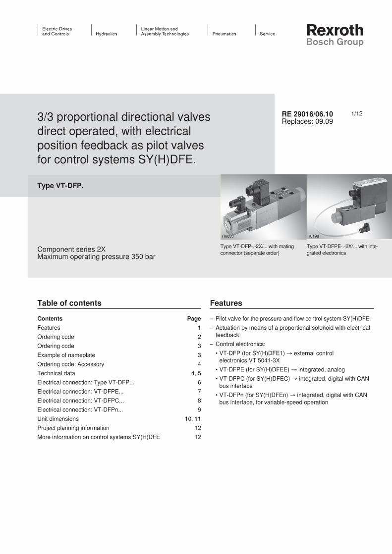
1/123/3 proportional directional valves direct operated, with electrical position feedback as pilot valves for control systems SY(H)DFE.
Type VT-DFP.
Component series 2XMaximum operating pressure 350 bar
RE 29016/06.10Replaces: 09.09
Type VT-DFPE-.-2X/... with inte-grated electronics
Type VT-DFP-.-2X/... with mating connector (separate order)
H6198H6633
Table of contents
Contents PageFeatures 1Ordering code 2Ordering code 3Example of nameplate 3Ordering code: Accessory 4Technical data 4, 5Electrical connection: Type VT-DFP... 6Electrical connection: VT-DFPE... 7Electrical connection: VT-DFPC... 8Electrical connection: VT-DFPn... 9Unit dimensions 10, 11Project planning information 12More information on control systems SY(H)DFE 12
Features
– Pilot valve for the pressure and flow control system SY(H)DFE.– Actuation by means of a proportional solenoid with electrical
feedback– Control electronics: •VT-DFP(forSY(H)DFE1)→ external control
electronics VT 5041-3X •VT-DFPE(forSY(H)DFEE)→ integrated, analog •VT-DFPC(forSY(H)DFEC)→ integrated, digital with CAN
bus interface •VT-DFPn(forSY(H)DFEn)→ integrated, digital with CAN
bus interface, for variable-speed operation
InhaltTable of contents 1Features 1Ordering code 2Ordering code 3Example of nameplate 3Ordering code: Accessories 4Technical data (For applications outside these parameters, please consult us!) 4Technical data (For applications outside these parameters, please consult us!) 5Electrical connection: Type VT-DFP... (for external analog electronics) 6Electrical connection: VT-DFPE... (with integrated analog electronics) 7Electrical connection: VT-DFPC... (with integrated digital elect-ronics) 8Electrical connection: VT-DFPn... (with integrated digital elect-ronics, variable-speed) 9Unit dimensions (dimensions in mm) 10Unit dimensions (dimensions in mm) 11Project planning information 12More information on control systems SY(H)DFE 12

2/12 Bosch Rexroth AG Hydraulics VT-DFP. RE 29016/06.10
Ordering code
VT-DFP - A - 2X / G24 K0 / 0 / V - *VT-DFPE - A - 2X / G24 K0 / 0 A 0 C / V - *VT-DFPC - A - 2X / G24 K0 / 0 A 0 C / V - *VT-DFPn - A - 2X / G24 K0 / 0 A 0 C / V - *
1 2 3 4 5 6 7 8 9 10 11
Series
1
Pilot valve for external electronics VT-DFPPilot valve with integrated analog electronics VT-DFPEPilot valve with integrated digital electronics VT-DFPCPilot valve with integrated digital electronics, variable-speed VT-DFPn
Spool design
2Standard (not for HFC fluids) A2-groove spool (not for new applications) B4-groove spool (e.g. for HFC fluids) C
3 Component series 2X
4 DC voltage 24V G24
5 Connector (without mating connector) 1) K0
Installation orientation plug-in connector (VT-DFP) and/or integrated electronics (also see page 3)
6Radially to the pump axis 0Folded 90° in the direction of the subplate with counterclockwise direction of rotation of the pump 1Folded 90° in the direction of the subplate with clockwise direction of rotation of the pump 2
Additional functions: Closed-loop control A B C D
7
VT-DFP (without)
VT-DFPE
Selectable pressure controller (high signal) ● APower limitation adjustable at the OBE valve ● BPower limitation adjustable via analog input ● CPressure controller that can be switched off (high signal) ● D
VT-DFPC Standard ● AVT-DFPn Standard ● A
Electronics assembly, option
8
VT-DFP (without)
VT-DFPE Standard electronics with leakage oil compensation ● - - ● 0Standard electronics without leakage oil compensation ● ● ● ● 1
VT-DFPC Standard ● 0VT-DFPn Standard ● 0
Actual pressure value input (description of the plug-in connectors on page 7, 8 and 9)
Plug-in con-nector
9
VT-DFP (without)
VT-DFPE VT-DFPC VT-DFPn
Current input 4...20 mA X1 CVoltage input 0...10 V (standard) X1 VVoltage input 1...10 V X1 EVoltage input 0.5...5 V (standard) 2) X2 F
10 FKM seals suitable for mineral oils (HL, HLP) according to DIN 51524 and HFC fluids 3) V
11 Further details in the plain text e.g. SO variant
●=Available -=Notavailable Standard program

Hydraulics Bosch Rexroth AGRE 29016/06.10 VT-DFP. 3/12
Ordering code
Note on feature 6: Installation orientation of the valve electronicsDirection of rotation clock-wise, installation orientation 0
Direction of rotation clockwise, installation orientation 2
Direction of rotation counter-clockwise, installation orienta-tion 0
Direction of rotation counter-clockwise, installation orien-tation 1
1) Connector dependent on the valve type (see technical data and electronic connection)2) With the SYDFEn control system with analog interfaces, the plug-in connector X2 cannot be used as actual pressure value
input. Thus, a separate pressure transducer has to be used and connected to plug-in connector X1 in this case.3) Only in connection with SYHDFE and spool design C (feature 2)
MNR: R900703575
V T - D F P E - A - 2 2 / G 2 4 K 0 / 0 A 0 E / V0 0 0 1 2 2 2 4 2 6 0 2
Made in Germany
FD: 09W26SN: 1
7087
1 2 3
45
Example of nameplate
1 Material number2 Serial number3 Date of manufacture4 Fabrication order number5 Type designation

4/12 Bosch Rexroth AG Hydraulics VT-DFP. RE 29016/06.10
Technical data (For applications outside these parameters, please consult us!)
generalType VT-DFP VT-DFPE VT-DFPC VT-DFPnStorage temperature range °C –20 … +70 0 … 70 0 … 70 0 … 70Ambient temperature range °C –20 … +60 0 … 60 0 … 50 0 … 50Weight kg 1.96 2.25 2.25 2.25
hydraulicHydraulic fluid Mineral oil (HL, HLP) according to DIN 51524; HFC fluid only in
connection with SYHDFE control system and C spool designHydraulic fluid temperature range °C –20 … +70Viscosity range mm2/s 20 … 380Maximum admissible degree of contamination of the hydraulic fluid according to ISO 4406 Class18/16/13(forparticlesize≤4/6/14μm)
Operating pressure Port A, P bar 350Port T bar 100
Ordering code: Accessories
Version 4/2009, enquire availability
Accessories for VT-DFP Material number Data sheetMating connector for solenoid plug R901017011Mating connector for position transducer of valve R900023126Compact power supply unit VT-NE32-1X R900080049 RE 29929
Accessories for VT-DFPE, VT-DFPC and VT-DFPn Material number Data sheetMating connector 12-pin for central connection X1 without cable (construction kit) R900884671Mating connector 12-pin for central connection X1 with cable set 2 x 5 m R900032356Mating connector 12-pin for central connection X1 with cable set 2 x 20 m R900860399Test device VT-PDFE-1-1X/V0/0 for SY(H)DFEE and SY(H)DFEC R900757051 RE 29689-BCompact power supply unit VT-NE32-1X R900080049 RE 29929
Accessories only for VT-DFPC and VT-DFPn (serial access) Material number Data sheetConverter USB serial for laptops without serial interface VT-ZKO-USB/S-1-1X/V0/0
R901066684
Cable for connecting a WIN-PED PC (RS232) to the X2 interface length 3 m
R901156928
T connector for the simultaneous connection of a WIN-PED PC (RS232) and use of the input at plug-in connector X2
R901117164

Hydraulics Bosch Rexroth AGRE 29016/06.10 VT-DFP. 5/12
electricalType VT-DFP VT-DFPE VT-DFPC VT-DFPn
Control
External control
electronics VT 5041-3X
Integrated, analog
Integrated, digital
Integrated, digital
Operating voltage UB
See data sheet
RE 30242
24 VDC+40 % –5 %
24 VDC+40 % –5 %
24 VDC+40 % –5 %
Operating range (short-time operation)Upper limit value UB(t)max 35 VLower limit value UB(t)min 21 V
Current consumption (in static control operation)Rated current INominal 0.6 AMaximum current Imax 1.25 A
Inputs
Actual pressure value input X1; pin 10 and 11
U or I Determi-nation by means of type code
Parameterizable:0...20 mA; 4...20 mA;
0...10 V;0…5 V; 0.5…5 V; 0.1...10 V;
1...10 VAnalog current inputs, load RB 100Ω 100Ω 100ΩAnalog voltage inputs RE ≥50kΩ ≥100kΩ ≥100kΩDigital inputs Logic 0 ≤0.6V ≤8V ≤8V
Logic 1 ≥21V ≥14V ≥14V
Outputs
pactual / UOUT1 1) UAImax
0…10 V1.5 mA
±10 V2 mA
±10 V2 mA
αactual / UOUT2 2) UAImax
±10 V1.5 mA
±10 V2 mA
±10 V2 mA
Digital outputs Logic 0 Ua < 1 VLogic 1 Ua≥UB – 5 V; 10 mA (short-circuit-proof)
Solenoid coil resistance Ω 2.1 ... 3.2Coil resistance position transducer at 20 °C
Between port 1 and 2 Ω Approx. 113Between port 3 and 4 Ω Approx. 101
Electrical connection See page 6 See page 7 See page 8 See page 9Protection class according to EN 60529 IP 65 with mounted and locked plug-in connectors
Technical data (For applications outside these parameters, please consult us!)
Note:Information on environment simulation testing for the areas EMC (electro-magnetic compatibility), climate and mechanical load, see RE 30030-U (declaration on environmental compatibility).
1, 2) With VT-DFPC and VT-DFPn, the outputs are parameterizable, condition as supplied see pages 8/9

30
27,5
30
36
5327,5
Ø19
M16 x 1,5
PE
1 2
PE
1 2
2
1
3
4
4 21 3
16 37
Ø 1
5
Pg7
23
7,8
6/12 Bosch Rexroth AG Hydraulics VT-DFP. RE 29016/06.10
Electrical connection: Type VT-DFP... (for external analog electronics)
SolenoidMating connector 3-pole Z4 M SW according to DIN EN 175301-803(separate order see page 4)
Connection at connector Connection at mating connector
To the amplifier
Inductive position transducerCoil connection Connector Connection at plug-in connector
(top view on connector)
Signal
Reference
Feed-in
ShieldAm
plifie
r
Mating connector 4-pole Pg7-G4W1F/Pg7 SW(separate order see page 4)
Details on the electrical connection to the VT 5041-3X amplifier are described in data sheet RE 30242.
1
2
345
6
7
8
9
10
11
90
33
5
3 4
12
Hydraulics Bosch Rexroth AGRE 29016/06.10 VT-DFP. 7/12
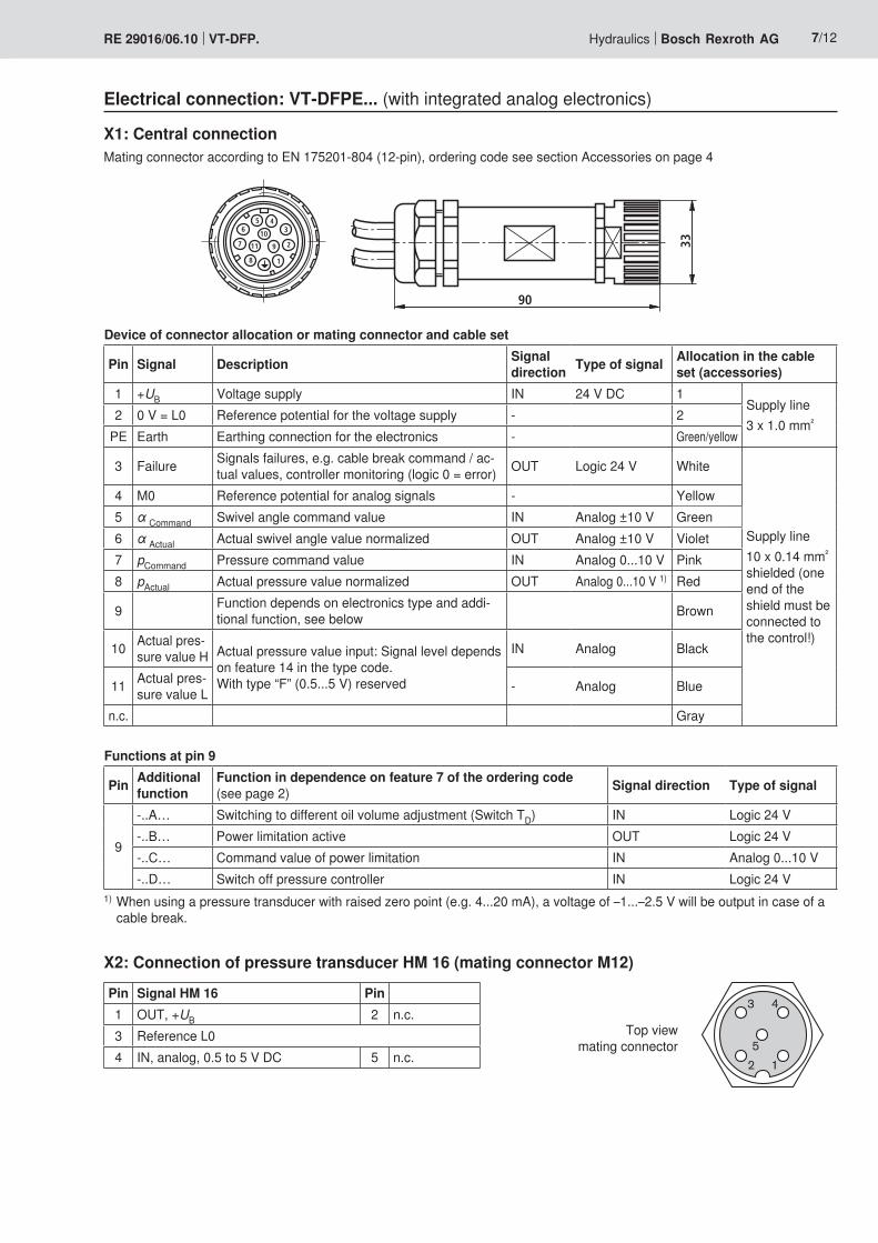
Electrical connection: VT-DFPE... (with integrated analog electronics)
X1: Central connectionMating connector according to EN 175201-804 (12-pin), ordering code see section Accessories on page 4
X2: Connection of pressure transducer HM 16 (mating connector M12)
Top view mating connector
Pin Signal HM 16 Pin1 OUT, +UB 2 n.c.3 Reference L04 IN, analog, 0.5 to 5 V DC 5 n.c.
Device of connector allocation or mating connector and cable set
Pin Signal Description Signal direction Type of signal Allocation in the cable
set (accessories)1 +UB Voltage supply IN 24 V DC 1
Supply line3 x 1.0 mm²2 0V=L0 Reference potential for the voltage supply - 2
PE Earth Earthing connection for the electronics - Green/yellow
3 Failure Signals failures, e.g. cable break command / ac-tualvalues,controllermonitoring(logic0=error) OUT Logic 24 V White
Supply line10 x 0.14 mm² shielded (one end of the shield must be connected to the control!)
4 M0 Reference potential for analog signals - Yellow5 α Command Swivel angle command value IN Analog ±10 V Green6 α Actual Actual swivel angle value normalized OUT Analog ±10 V Violet7 pCommand Pressure command value IN Analog 0...10 V Pink8 pActual Actual pressure value normalized OUT Analog 0...10 V 1) Red
9 Function depends on electronics type and addi-tional function, see below Brown
10 Actual pres-sure value H Actual pressure value input: Signal level depends
on feature 14 in the type code. With type “F” (0.5...5 V) reserved
IN Analog Black
11 Actual pres-sure value L - Analog Blue
n.c. Gray
Functions at pin 9
Pin Additional function
Function in dependence on feature 7 of the ordering code (see page 2) Signal direction Type of signal
9
-..A… Switching to different oil volume adjustment (Switch TD) IN Logic 24 V-..B… Power limitation active OUT Logic 24 V-..C… Command value of power limitation IN Analog 0...10 V-..D… Switch off pressure controller IN Logic 24 V
1) When using a pressure transducer with raised zero point (e.g. 4...20 mA), a voltage of –1...–2.5 V will be output in case of a cable break.
5
3 4
12
1
2
345
6
7
8
9
10
11
90
33
3
12
3
12
3
12
5
4 3
21
8/12 Bosch Rexroth AG Hydraulics VT-DFP. RE 29016/06.10
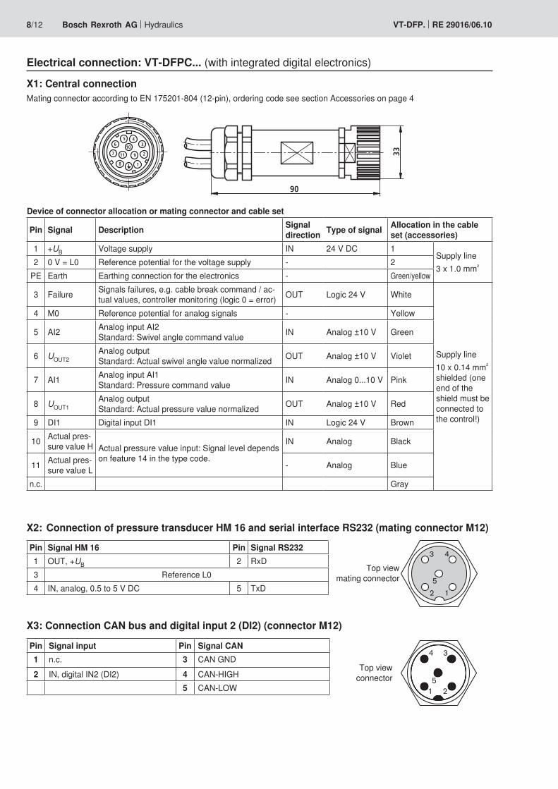
Electrical connection: VT-DFPC... (with integrated digital electronics)
X2: Connection of pressure transducer HM 16 and serial interface RS232 (mating connector M12)
Device of connector allocation or mating connector and cable set
Pin Signal Description Signal direction Type of signal Allocation in the cable
set (accessories)1 +UB Voltage supply IN 24 V DC 1
Supply line3 x 1.0 mm²2 0V=L0 Reference potential for the voltage supply - 2
PE Earth Earthing connection for the electronics - Green/yellow
3 Failure Signals failures, e.g. cable break command / ac-tualvalues,controllermonitoring(logic0=error) OUT Logic 24 V White
Supply line10 x 0.14 mm² shielded (one end of the shield must be connected to the control!)
4 M0 Reference potential for analog signals - Yellow
5 AI2 Analog input AI2 Standard: Swivel angle command value IN Analog ±10 V Green
6 UOUT2Analog output Standard: Actual swivel angle value normalized OUT Analog ±10 V Violet
7 AI1 Analog input AI1 Standard: Pressure command value IN Analog 0...10 V Pink
8 UOUT1Analog output Standard: Actual pressure value normalized OUT Analog ±10 V Red
9 DI1 Digital input DI1 IN Logic 24 V Brown
10 Actual pres-sure value H Actual pressure value input: Signal level depends
on feature 14 in the type code.
IN Analog Black
11 Actual pres-sure value L - Analog Blue
n.c. Gray
X1: Central connectionMating connector according to EN 175201-804 (12-pin), ordering code see section Accessories on page 4
X3: Connection CAN bus and digital input 2 (DI2) (connector M12)
Top view connector
Pin Signal HM 16 Pin Signal RS2321 OUT, +UB 2 RxD3 Reference L04 IN, analog, 0.5 to 5 V DC 5 TxD
Top view mating connector
Pin Signal input Pin Signal CAN1 n.c. 3 CAN GND2 IN, digital IN2 (DI2) 4 CAN-HIGH
5 CAN-LOW
1
2
345
6
7
8
9
10
11
90
33
3
12
3
12
3
12
5
4 3
21
5
3 4
12
Hydraulics Bosch Rexroth AGRE 29016/06.10 VT-DFP. 9/12
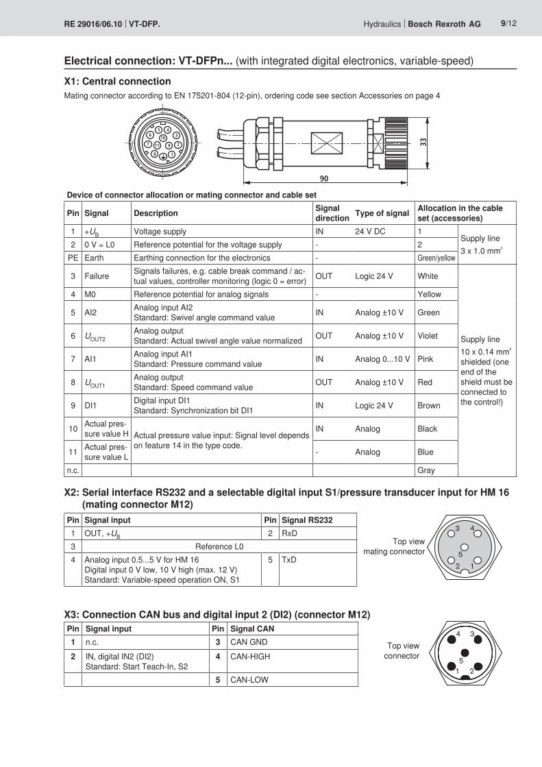
Electrical connection: VT-DFPn... (with integrated digital electronics, variable-speed)
Device of connector allocation or mating connector and cable set
Pin Signal Description Signal direction Type of signal Allocation in the cable
set (accessories)1 +UB Voltage supply IN 24 V DC 1
Supply line3 x 1.0 mm²2 0V=L0 Reference potential for the voltage supply - 2
PE Earth Earthing connection for the electronics - Green/yellow
3 Failure Signals failures, e.g. cable break command / ac-tualvalues,controllermonitoring(logic0=error) OUT Logic 24 V White
Supply line10 x 0.14 mm² shielded (one end of the shield must be connected to the control!)
4 M0 Reference potential for analog signals - Yellow
5 AI2 Analog input AI2 Standard: Swivel angle command value IN Analog ±10 V Green
6 UOUT2Analog output Standard: Actual swivel angle value normalized OUT Analog ±10 V Violet
7 AI1 Analog input AI1 Standard: Pressure command value IN Analog 0...10 V Pink
8 UOUT1Analog output Standard: Speed command value OUT Analog ±10 V Red
9 DI1 Digital input DI1 Standard: Synchronization bit DI1 IN Logic 24 V Brown
10 Actual pres-sure value H Actual pressure value input: Signal level depends
on feature 14 in the type code.
IN Analog Black
11 Actual pres-sure value L - Analog Blue
n.c. Gray
X1: Central connectionMating connector according to EN 175201-804 (12-pin), ordering code see section Accessories on page 4
Top view connector
X3: Connection CAN bus and digital input 2 (DI2) (connector M12)
X2: Serial interface RS232 and a selectable digital input S1/pressure transducer input for HM 16 (mating connector M12)
Pin Signal input Pin Signal RS2321 OUT, +UB 2 RxD3 Reference L04 Analog input 0.5...5 V for HM 16
Digital input 0 V low, 10 V high (max. 12 V) Standard: Variable-speed operation ON, S1
5 TxD
Pin Signal input Pin Signal CAN1 n.c. 3 CAN GND2 IN, digital IN2 (DI2)
Standard: Start Teach-In, S24 CAN-HIGH
5 CAN-LOW
Top view mating connector
35,7
4 2
1 3
85
80132
220
32 46,8
55,5
15
(45)10
AT P
AT P
80
3415
7130
7,5 2016
34
7347 30
15
4
1
3a
2 5 14
6
8
45
80
217,5
32 46,8
126,
5
(45)81
AT P
80
3415
71
307,
5
60121,5
9 3b 710
68 152
136,
5
13 12
45
0123456789
ABCDEF
0,01/100
Rzmax 4
10/12 Bosch Rexroth AG Hydraulics VT-DFP. RE 29016/06.10
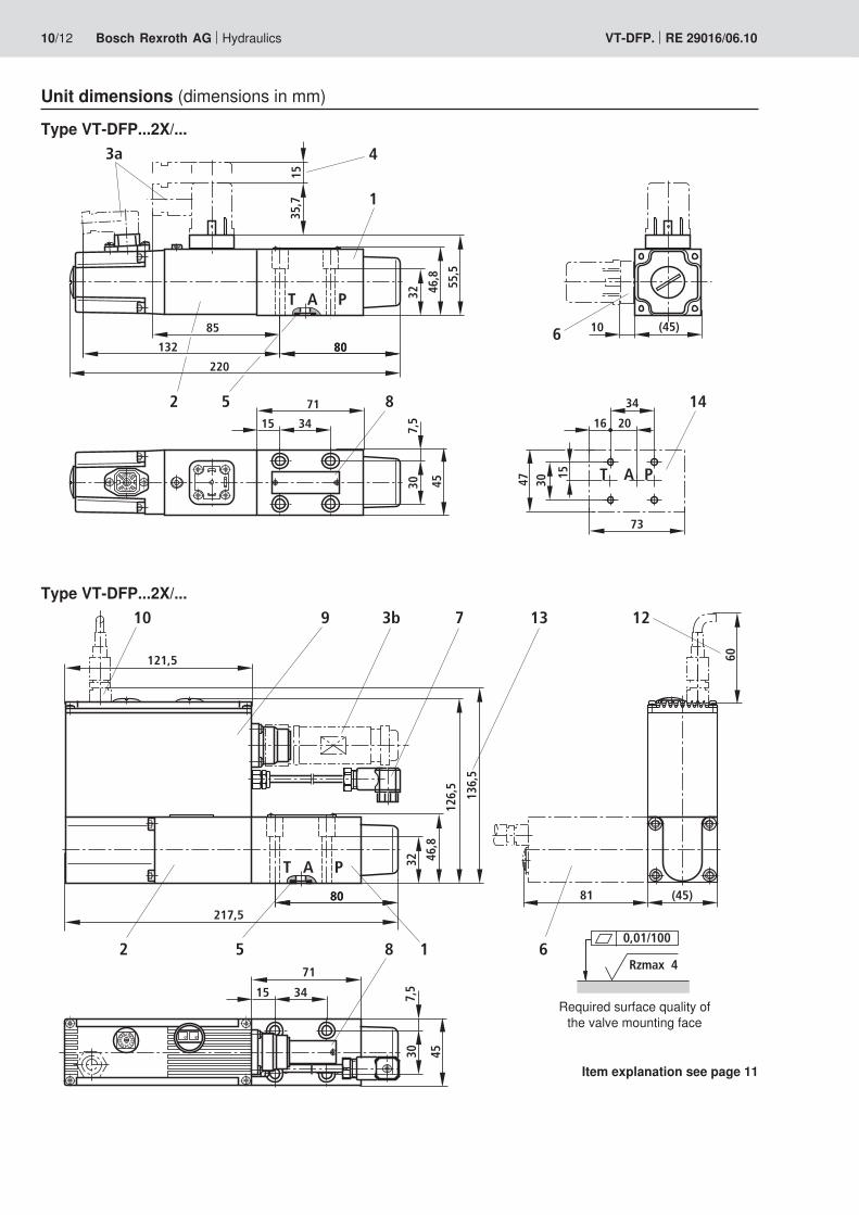
Unit dimensions (dimensions in mm)
Type VT-DFP...2X/...
Type VT-DFP...2X/...
Item explanation see page 11
Required surface quality of the valve mounting face
80
217,5
32 46,8
136,
5
(45)81
AT P
80
3415
71
307,
5
≥ 10
0
121,5
9 3b 710
6
8 152
11
AT P
2016
34
73
47 30
15
14
15
45
13
100
11 1012
0123456789
ABCDEF
Hydraulics Bosch Rexroth AGRE 29016/06.10 VT-DFP. 11/12
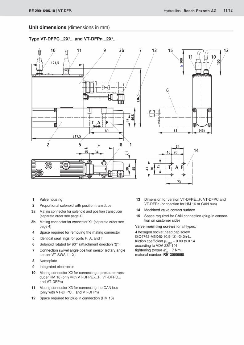
Unit dimensions (dimensions in mm)
Type VT-DFPC...2X/... and VT-DFPn...2X/...
1 Valve housing2 Proportional solenoid with position transducer3a Mating connector for solenoid and position transducer
(separate order see page 4)3b Mating connector for connector X1 (separate order see
page 4)4 Space required for removing the mating connector5 Identical seal rings for ports P, A, and T6 Solenoid rotated by 90° (attachment direction “2”)7 Connection swivel angle position sensor (rotary angle
sensor VT-SWA-1-1X)8 Nameplate9 Integrated electronics10 Mating connector X2 for connecting a pressure trans-
ducer HM 16 (only with VT-DFPE./...F, VT-DFPC... and VT-DFPn)
11 Mating connector X3 for connecting the CAN bus (only with VT-DFPC... and VT-DFPn)
12 Space required for plug-in connection (HM 16)
13 Dimension for version VT-DFPE...F, VT-DFPC and VT-DFPn (connection for HM 16 or CAN bus)
14 Machined valve contact surface15 Space required for CAN connection (plug-in connec-
tion on customer side)Valve mounting screws for all types:4 hexagon socket head cap screw ISO4762-M6X40-10.9-flZn-240h-L, frictioncoefficientμTotal=0.09to0.14 according to VDA 235-101, tightening torque MA=7Nm, material number: R913000058

Bosch Rexroth AG HydraulicsZum Eisengießer 197816 Lohr am Main, Germany Phone +49 (0) 93 52 / 18-0 Fax +49 (0) 93 52 / 18-23 [email protected] www.boschrexroth.de
© This document, as well as the data, specifications and other informa-tion set forth in it, are the exclusive property of Bosch Rexroth AG. It may not be reproduced or given to third parties without its consent.The data specified above only serve to describe the product. No state-ments concerning a certain condition or suitability for a certain applica-tion can be derived from our information. The information given does not release the user from the obligation of own judgment and verification. It must be remembered that our products are subject to a natural process of wear and aging.
12/12 Bosch Rexroth AG Hydraulics VT-DFP. RE 29016/06.10
Project planning information
Supplementary notes on the SY(H)DFE control systems can be found in the operating instructions (See section “Further infor-mation about this control system” on this page.).
More information on control systems SY(H)DFE
Operating instructions for SY(H)DFE1 RE 30011-BOperating instructions for SY(H)DFEE RE 30012-BOperating instructions for SY(H)DFEC RE 30027-BOperating instructions for SY(H)DFEn (in preparation) RE 30014-BData sheet for SYDFE.-2X RE 30030Data sheet for SYDFE.-3X RE 30630Data sheet for SYHDFE.-1X RE 30035Data sheet for external control electronics VT 5041-3X for SYDFE1 RE 30242Data sheet for swivel angle sensor VT-SWA-1-1X RE 30268Data sheet for pressure transducer HM 12-1X and HM 13-1X RE 29933Data sheet for pressure transducer HM 16-1X RE 30266Data sheet for pressure transducer HM 17-1X RE 30269Operating instructions for test device VT-PDFE RE 29689-BCurrent information is also available on the Internet under the address http://www.boschrexroth.com/sydfe (English) or http://www.boschrexroth.de/sydfe (German).