332 advanced computer architecture introduction … architecture/lecture1.pdfadvanced computer...
TRANSCRIPT
Advanced Computer Architecture Chapter 1. p1
January 2007Paul H J Kelly
These lecture notes are partly based on the course text, Hennessy and Patterson’s Computer Architecture, a
quantitative approach (4th ed), and on the lecture slides of David Patterson’s Berkeley course (CS252)
332Advanced Computer Architecture
Chapter 1
Introduction and review of Pipelines, Performance, Caches, and Virtual
Memory
Course materials online at http://www.doc.ic.ac.uk/~phjk/AdvancedCompArchitecture.html
Advanced Computer Architecture Chapter 1. p2
Pre-requisitesThis a third-level computer architecture course
The usual path would be to take this course after following a course based on a textbook like “Computer Organization and Design” (Patterson and Hennessy, Morgan Kaufmann)
This course is based on the more advanced book by the same authors (see next slide)
You can take this course provided you’re prepared to catch up if necessary
Read chapters 1 to 8 of “Computer Organization and Design” (COD) if this material is new to youIf you have studied computer architecture before, make sure COD Chapters 2, 6, 7 are familiarSee also “Appendix A Pipelining: Basic and Intermediate Concepts” of course textbook
FAST review today of Pipelining, Performance, Caches, and Virtual Memory
Advanced Computer Architecture Chapter 1. p3
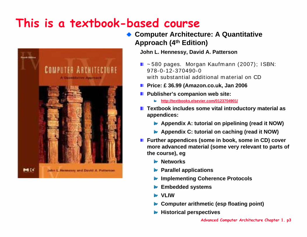
This is a textbook-based courseComputer Architecture: A Quantitative Approach (4th Edition)
John L. Hennessy, David A. Patterson
~580 pages. Morgan Kaufmann (2007); ISBN: 978-0-12-370490-0with substantial additional material on CD
Price: £ 36.99 (Amazon.co.uk, Jan 2006Publisher’s companion web site:
http://textbooks.elsevier.com/0123704901/
Textbook includes some vital introductory material as appendices:
Appendix A: tutorial on pipelining (read it NOW)Appendix C: tutorial on caching (read it NOW)
Further appendices (some in book, some in CD) cover more advanced material (some very relevant to parts of the course), eg
NetworksParallel applicationsImplementing Coherence ProtocolsEmbedded systemsVLIWComputer arithmetic (esp floating point)Historical perspectives
Advanced Computer Architecture Chapter 1. p4
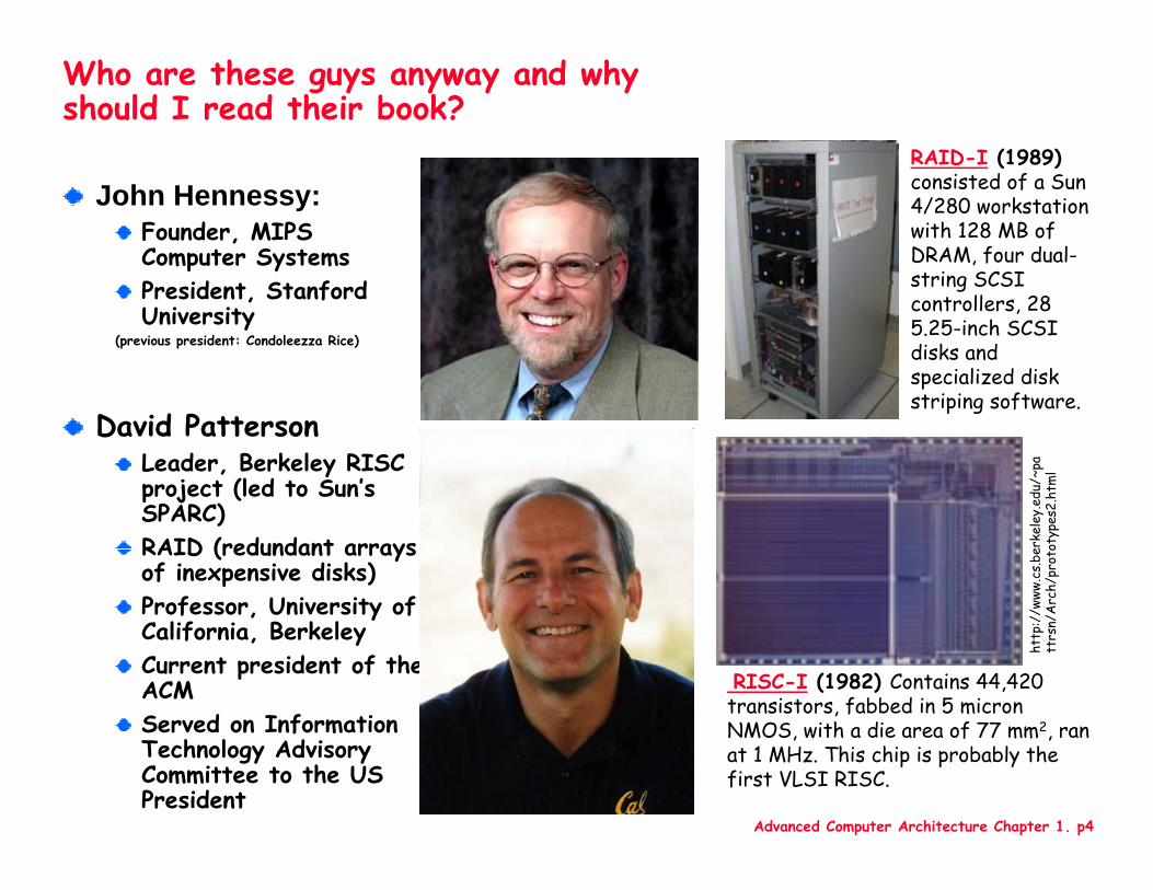
Who are these guys anyway and why should I read their book?
John Hennessy:Founder, MIPS Computer SystemsPresident, Stanford University
(previous president: Condoleezza Rice)
David PattersonLeader, Berkeley RISC project (led to Sun’s SPARC)RAID (redundant arrays of inexpensive disks)Professor, University of California, BerkeleyCurrent president of the ACMServed on Information Technology Advisory Committee to the US President
RAID-I (1989) consisted of a Sun 4/280 workstation with 128 MB of DRAM, four dual-string SCSI controllers, 28 5.25-inch SCSI disks and specialized disk striping software.
RISC-I (1982) Contains 44,420 transistors, fabbed in 5 micron NMOS, with a die area of 77 mm2, ran at 1 MHz. This chip is probably the first VLSI RISC.
http
://w
ww.c
s.be
rkel
ey.e
du/~
patt
rsn/
Arc
h/pr
otot
ypes
2.ht
ml
Advanced Computer Architecture Chapter 1. p5
Administration details
Course web site:http://www.doc.ic.ac.uk/~phjk/AdvancedCompArchitecture.html
Course mailing list (see web page for link):[email protected]
Mailing list archive:http://mailman.doc.ic.ac.uk/pipermail/332-advancedcomputerarchitecture-2006/
Course textbook: H&P 4th edRead Appendix A right away
Advanced Computer Architecture Chapter 1. p6
Course organisationLecturer: Paul Kelly
Tutorial helper:Ashley Brown – PhD student working on heterogenous multicore architectures and design-space exploration
3 hours per week Nominally two hours of lectures, one hour of classroom tutorialsWe will use the time more flexibly
Assessment:Exam
For CS M.Eng. Class, exam will take place in last week of termFor everyone else, exam will take place early in the summer termThe goal of the course is to teach you how to think about computer architectureThe exam usually includes some architectural ideas not presented in the lectures
CourseworkYou will be assigned a substantial, laboratory-based exerciseYou will learn about performance tuning for computationally-intensive kernelsYou will learn about using simulators, and experimentally evaluating hypotheses to understand system performanceYou are encouraged to bring laptops to class to get started and get help during tutorials
Please do not use the computers for anything else during classes
Advanced Computer Architecture Chapter 1. p7
Course overview (plan)
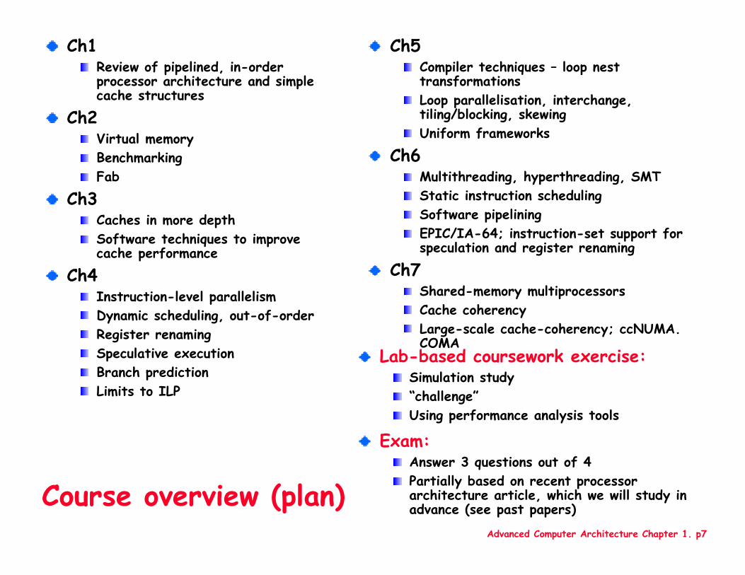
Ch1Review of pipelined, in-order processor architecture and simple cache structures
Ch2Virtual memoryBenchmarkingFab
Ch3Caches in more depthSoftware techniques to improve cache performance
Ch4Instruction-level parallelismDynamic scheduling, out-of-orderRegister renamingSpeculative executionBranch predictionLimits to ILP
Ch5Compiler techniques – loop nest transformationsLoop parallelisation, interchange, tiling/blocking, skewingUniform frameworks
Ch6Multithreading, hyperthreading, SMTStatic instruction schedulingSoftware pipeliningEPIC/IA-64; instruction-set support for speculation and register renaming
Ch7 Shared-memory multiprocessorsCache coherencyLarge-scale cache-coherency; ccNUMA. COMA
Lab-based coursework exercise: Simulation study“challenge”Using performance analysis tools
Exam:Answer 3 questions out of 4Partially based on recent processor architecture article, which we will study in advance (see past papers)
Advanced Computer Architecture Chapter 1. p8
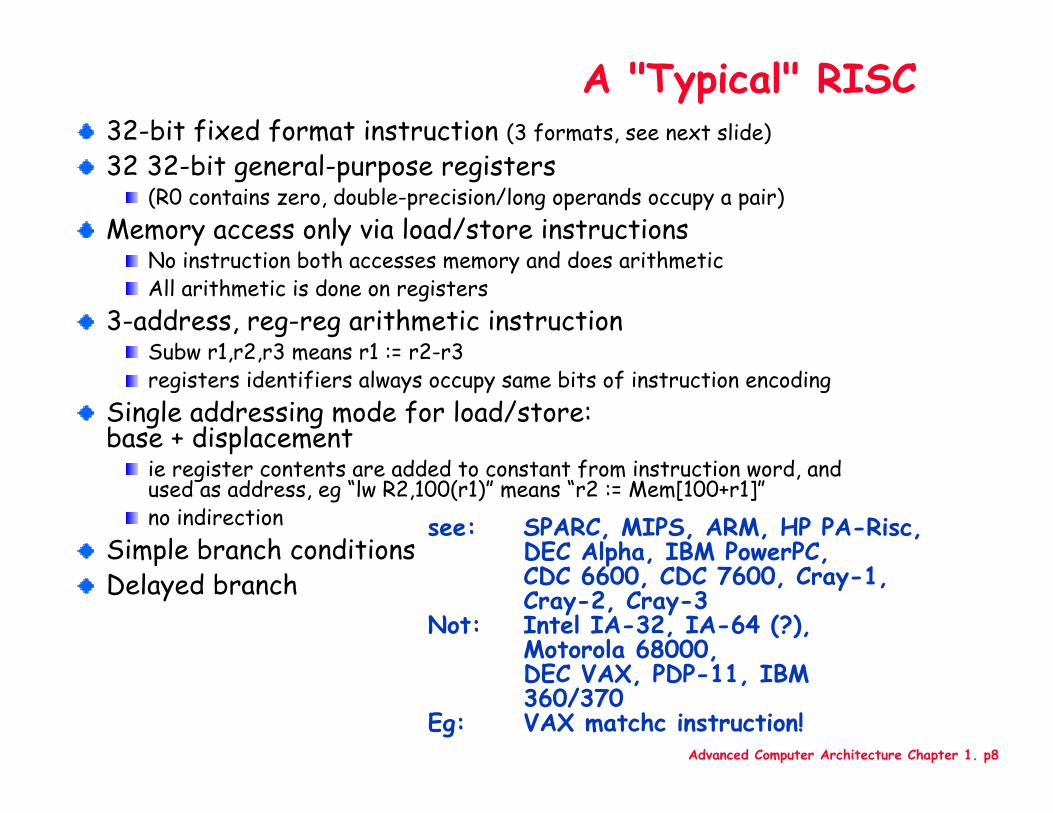
A "Typical" RISC32-bit fixed format instruction (3 formats, see next slide)32 32-bit general-purpose registers
(R0 contains zero, double-precision/long operands occupy a pair)Memory access only via load/store instructions
No instruction both accesses memory and does arithmeticAll arithmetic is done on registers
3-address, reg-reg arithmetic instructionSubw r1,r2,r3 means r1 := r2-r3registers identifiers always occupy same bits of instruction encoding
Single addressing mode for load/store: base + displacement
ie register contents are added to constant from instruction word, and used as address, eg “lw R2,100(r1)” means “r2 := Mem[100+r1]”no indirection
Simple branch conditionsDelayed branch
see: SPARC, MIPS, ARM, HP PA-Risc,DEC Alpha, IBM PowerPC, CDC 6600, CDC 7600, Cray-1, Cray-2, Cray-3
Not: Intel IA-32, IA-64 (?),Motorola 68000, DEC VAX, PDP-11, IBM 360/370
Eg: VAX matchc instruction!

Advanced Computer Architecture Chapter 1. p9
Example: MIPS (Note register location)
Op31 26 01516202125
Rs1 Rd immediate
Op31 26 025
Op31 26 01516202125
Rs1 Rs2
target
Rd Opx
Register-Register561011
Register-Immediate
Op31 26 01516202125
Rs1 Rs2/Opx immediate
Branch
Jump / Call
Q: What is the largest signed immediate operand for “subw r1,r2,X”?Q: What range of addresses can a conditional branch jump to?
Advanced Computer Architecture Chapter 1. p10
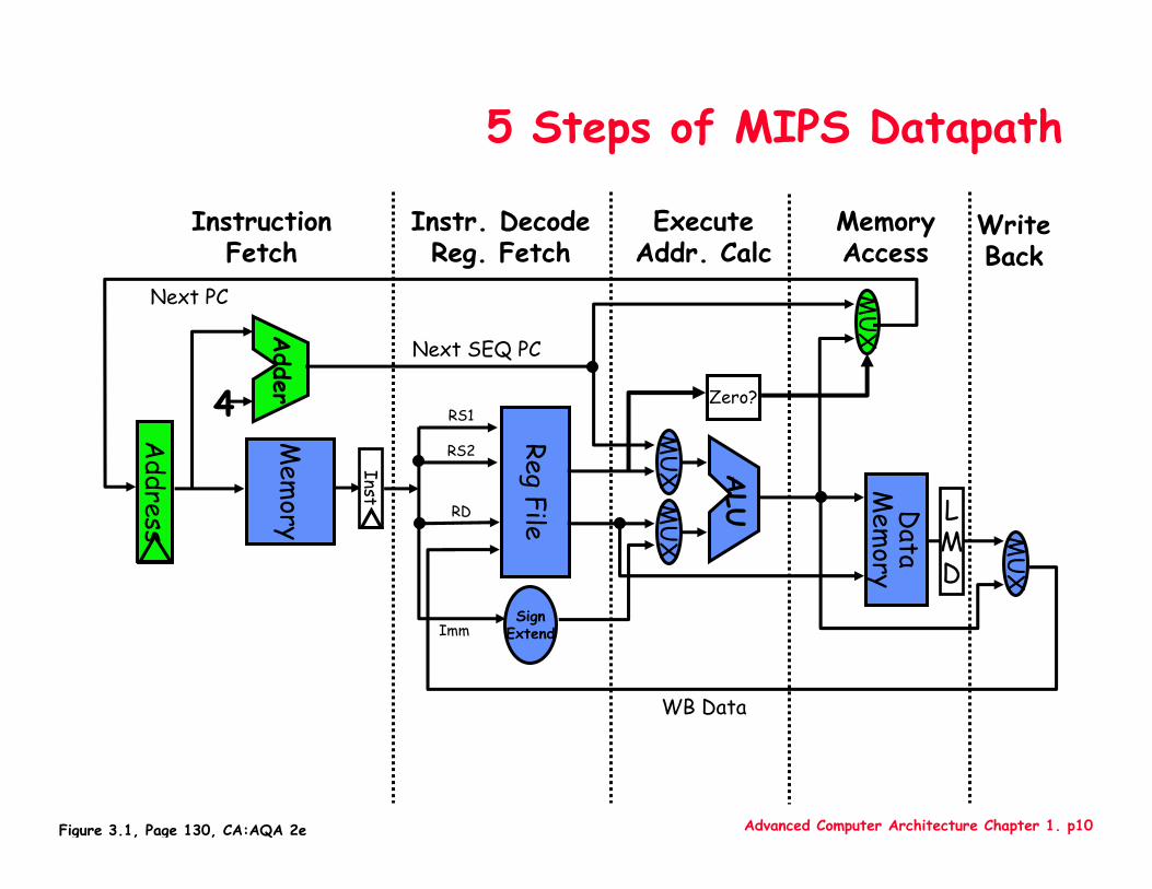
5 Steps of MIPS Datapath
MemoryAccess
WriteBack
InstructionFetch
Instr. DecodeReg. Fetch
ExecuteAddr. Calc
LMD
ALU
MU
X
Mem
ory
RegFile
MU
XM
UX
Data
Mem
ory
MU
X
SignExtend
4
Adder Zero?
Next SEQ PC
Address
Next PC
WB Data
Inst
RD
RS1
RS2
Imm
Figure 3.1, Page 130, CA:AQA 2e
Advanced Computer Architecture Chapter 1. p11
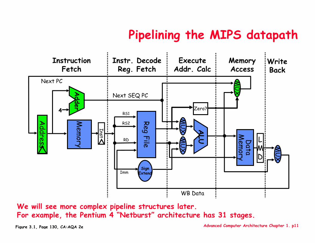
Pipelining the MIPS datapath
MemoryAccess
WriteBack
InstructionFetch
Instr. DecodeReg. Fetch
ExecuteAddr. Calc
LMD
ALU
MU
X
Mem
ory
RegFile
MU
XM
UX
Data
Mem
ory
MU
X
SignExtend
4
Adder Zero?
Next SEQ PC
Address
Next PC
WB Data
Inst
RD
RS1
RS2
Imm
Figure 3.1, Page 130, CA:AQA 2e
We will see more complex pipeline structures later.For example, the Pentium 4 “Netburst” architecture has 31 stages.
Advanced Computer Architecture Chapter 1. p12
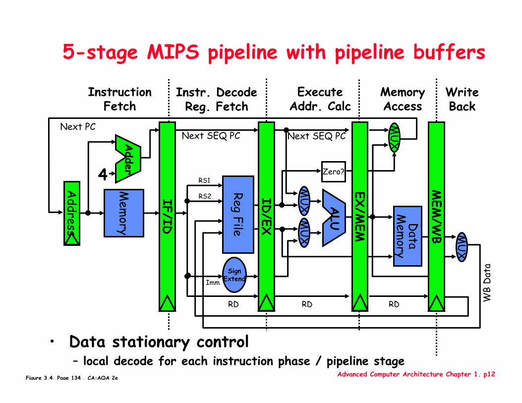
5-stage MIPS pipeline with pipeline buffers
MemoryAccess
WriteBack
InstructionFetch
Instr. DecodeReg. Fetch
ExecuteAddr. Calc
ALU
Mem
ory
RegFile
MU
XM
UX
Data
Mem
ory
MU
X
SignExtend
Zero?
IF/ID
ID/EX
MEM
/WB
EX/M
EM4
Adder
Next SEQ PC Next SEQ PC
RD RD RD WB
Dat
a
• Data stationary control– local decode for each instruction phase / pipeline stage
Next PC
Address
RS1
RS2
Imm
MU
X
Figure 3.4, Page 134 , CA:AQA 2e
Advanced Computer Architecture Chapter 1. p13
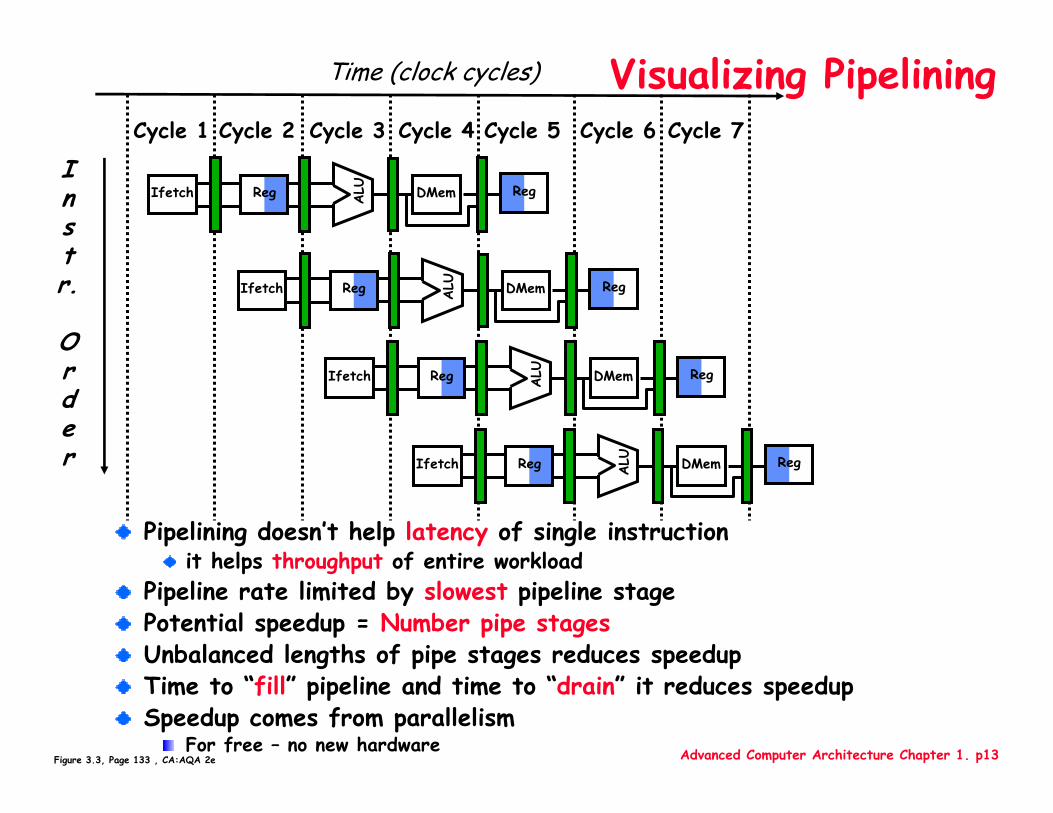
Visualizing Pipelining
Instr.
Order
Time (clock cycles)
Reg ALU DMemIfetch Reg
Reg ALU DMemIfetch Reg
Reg ALU DMemIfetch Reg
Reg ALU DMemIfetch Reg
Cycle 1 Cycle 2 Cycle 3 Cycle 4 Cycle 6 Cycle 7Cycle 5
Figure 3.3, Page 133 , CA:AQA 2e
Pipelining doesn’t help latency of single instructionit helps throughput of entire workload
Pipeline rate limited by slowest pipeline stagePotential speedup = Number pipe stagesUnbalanced lengths of pipe stages reduces speedupTime to “fill” pipeline and time to “drain” it reduces speedupSpeedup comes from parallelism
For free – no new hardware
Advanced Computer Architecture Chapter 1. p14
It’s Not That Easy for Computers
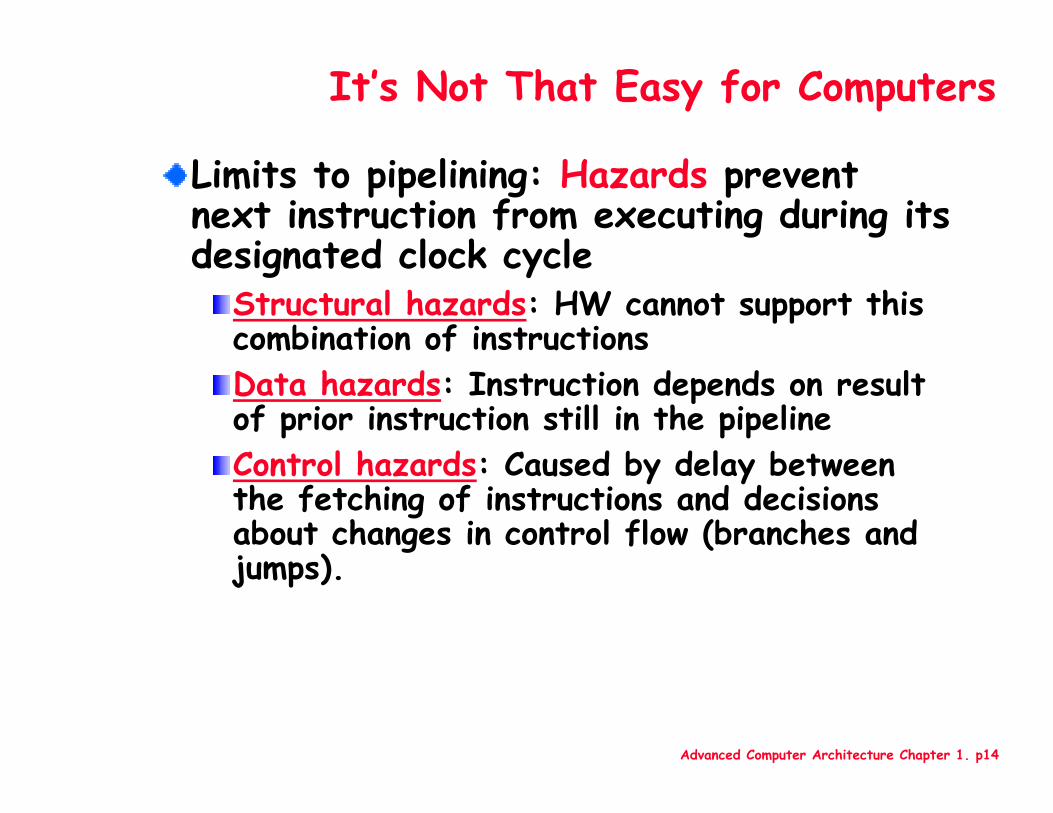
Limits to pipelining: Hazards prevent next instruction from executing during its designated clock cycle
Structural hazards: HW cannot support this combination of instructions Data hazards: Instruction depends on result of prior instruction still in the pipeline Control hazards: Caused by delay between the fetching of instructions and decisions about changes in control flow (branches and jumps).
Advanced Computer Architecture Chapter 1. p15
One Memory Port/Structural Hazards
Instr.
Order
Time (clock cycles)
Load
Instr 1
Instr 2
Instr 3
Instr 4
Reg ALU DMemIfetch Reg
Reg ALU DMemIfetch Reg
Reg ALU DMemIfetch Reg
Reg ALU DMemIfetch Reg
Cycle 1 Cycle 2 Cycle 3 Cycle 4 Cycle 6 Cycle 7Cycle 5
Reg ALU DMemIfetch Reg
Figure 3.6, Page 142 , CA:AQA 2e
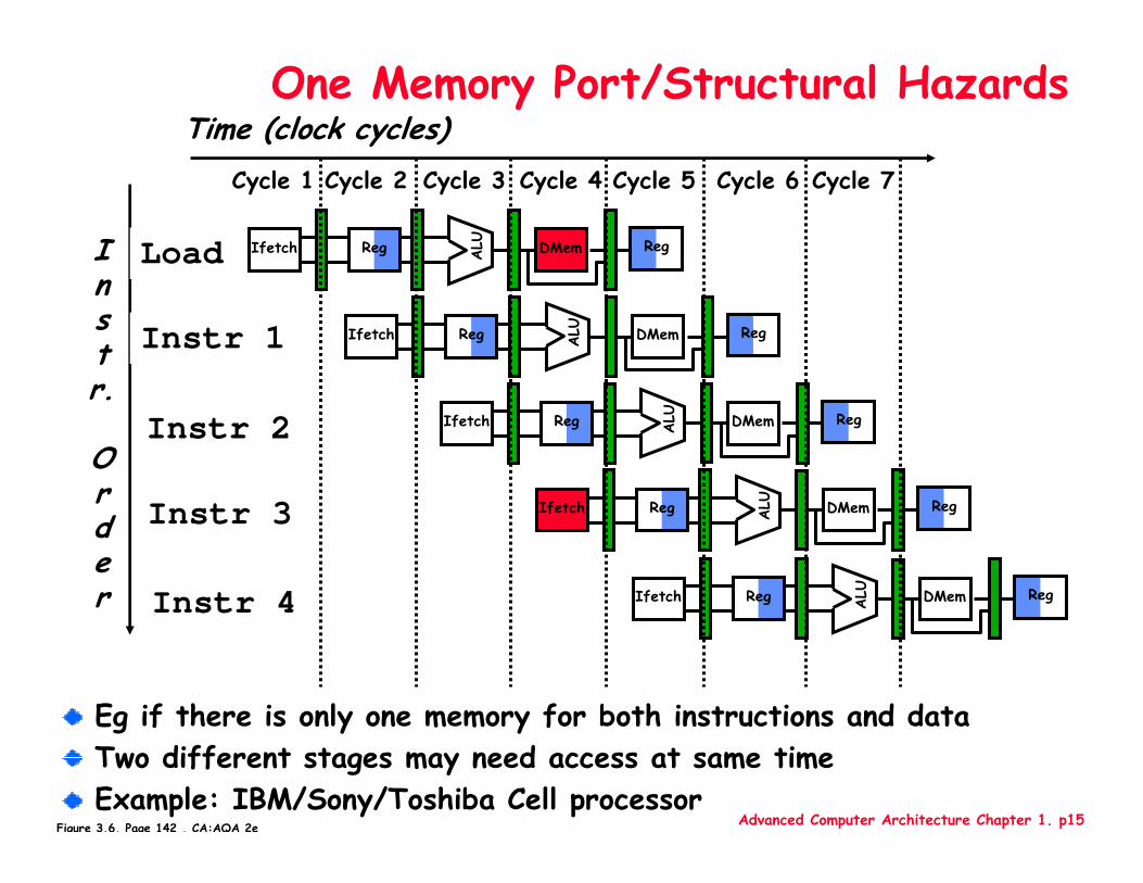
Eg if there is only one memory for both instructions and dataTwo different stages may need access at same timeExample: IBM/Sony/Toshiba Cell processor
Advanced Computer Architecture Chapter 1. p16
One Memory Port/Structural Hazards
Instr.
Order
Time (clock cycles)
Load
Instr 1
Instr 2
Stall
Instr 3
Reg ALU DMemIfetch Reg
Reg ALU DMemIfetch Reg
Reg ALU DMemIfetch Reg
Cycle 1 Cycle 2 Cycle 3 Cycle 4 Cycle 6 Cycle 7Cycle 5
Reg ALU DMemIfetch Reg
Bubble Bubble Bubble BubbleBubble
Figure 3.7, Page 143 , CA:AQA 2e
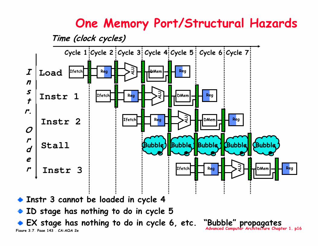
Instr 3 cannot be loaded in cycle 4ID stage has nothing to do in cycle 5EX stage has nothing to do in cycle 6, etc. “Bubble” propagates
Advanced Computer Architecture Chapter 1. p17
Instr.
Order
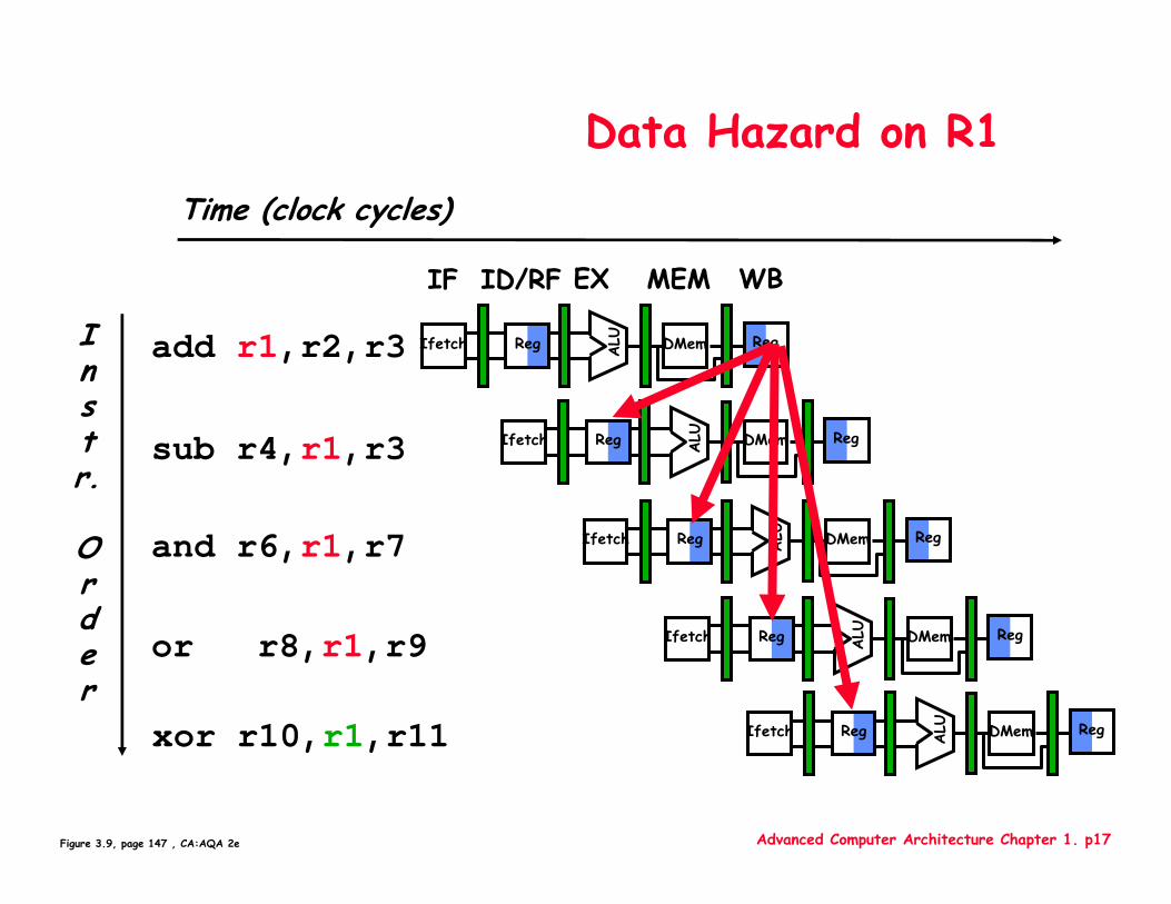
add r1,r2,r3
sub r4,r1,r3
and r6,r1,r7
or r8,r1,r9
xor r10,r1,r11
Reg ALU DMemIfetch Reg
Reg ALU DMemIfetch Reg
Reg ALU DMemIfetch Reg
Reg ALU DMemIfetch Reg
Reg ALU DMemIfetch Reg
Data Hazard on R1Time (clock cycles)
IF ID/RF EX MEM WB
Figure 3.9, page 147 , CA:AQA 2e
Advanced Computer Architecture Chapter 1. p18
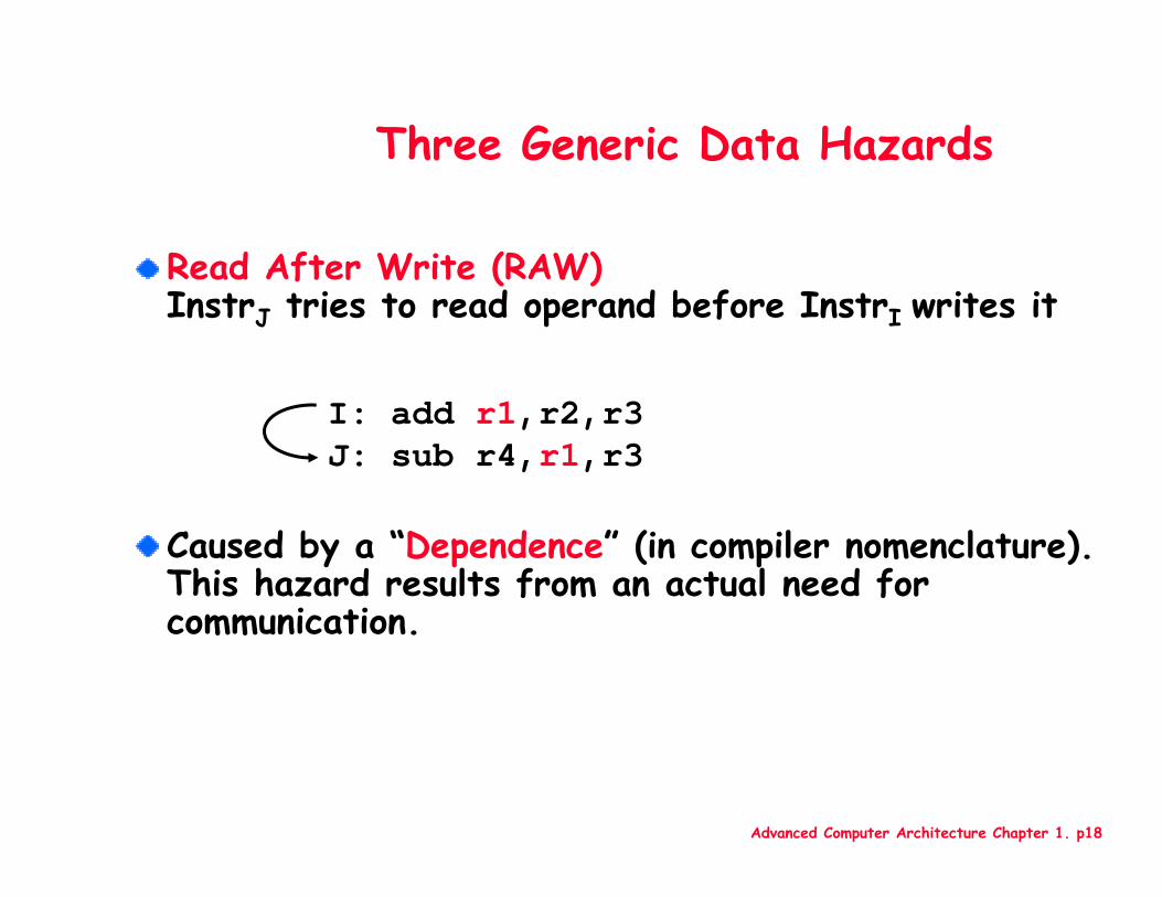
Read After Write (RAW)InstrJ tries to read operand before InstrI writes it
Caused by a “Dependence” (in compiler nomenclature). This hazard results from an actual need for communication.
Three Generic Data Hazards
I: add r1,r2,r3J: sub r4,r1,r3
Advanced Computer Architecture Chapter 1. p19
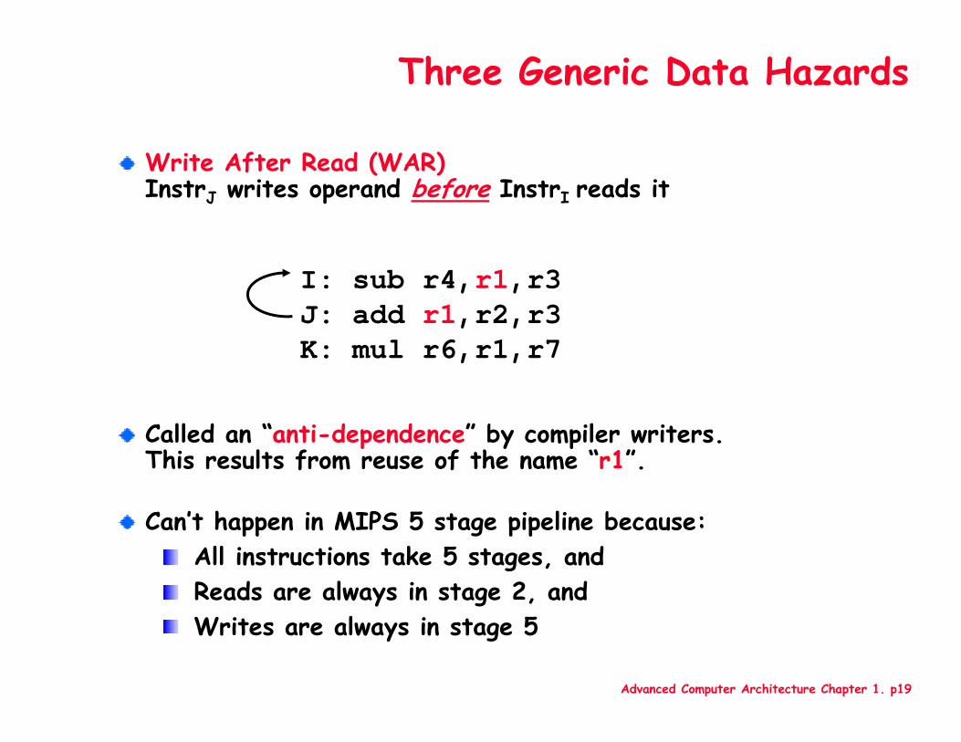
Write After Read (WAR)InstrJ writes operand before InstrI reads it
Called an “anti-dependence” by compiler writers.This results from reuse of the name “r1”.
Can’t happen in MIPS 5 stage pipeline because:All instructions take 5 stages, andReads are always in stage 2, and Writes are always in stage 5
I: sub r4,r1,r3 J: add r1,r2,r3K: mul r6,r1,r7
Three Generic Data Hazards
Advanced Computer Architecture Chapter 1. p20
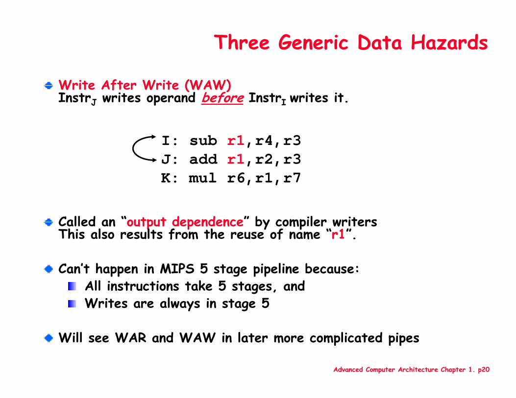
Three Generic Data Hazards
Write After Write (WAW)InstrJ writes operand before InstrI writes it.
Called an “output dependence” by compiler writersThis also results from the reuse of name “r1”.
Can’t happen in MIPS 5 stage pipeline because: All instructions take 5 stages, and Writes are always in stage 5
Will see WAR and WAW in later more complicated pipes
I: sub r1,r4,r3 J: add r1,r2,r3K: mul r6,r1,r7
Advanced Computer Architecture Chapter 1. p21
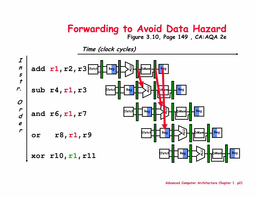
Time (clock cycles)
Forwarding to Avoid Data HazardFigure 3.10, Page 149 , CA:AQA 2e
Inst
r.
Order
add r1,r2,r3
sub r4,r1,r3
and r6,r1,r7
or r8,r1,r9
xor r10,r1,r11
Reg ALU DMemIfetch Reg
Reg ALU DMemIfetch Reg
Reg ALU DMemIfetch Reg
Reg ALU DMemIfetch Reg
Reg ALU DMemIfetch Reg
Advanced Computer Architecture Chapter 1. p22
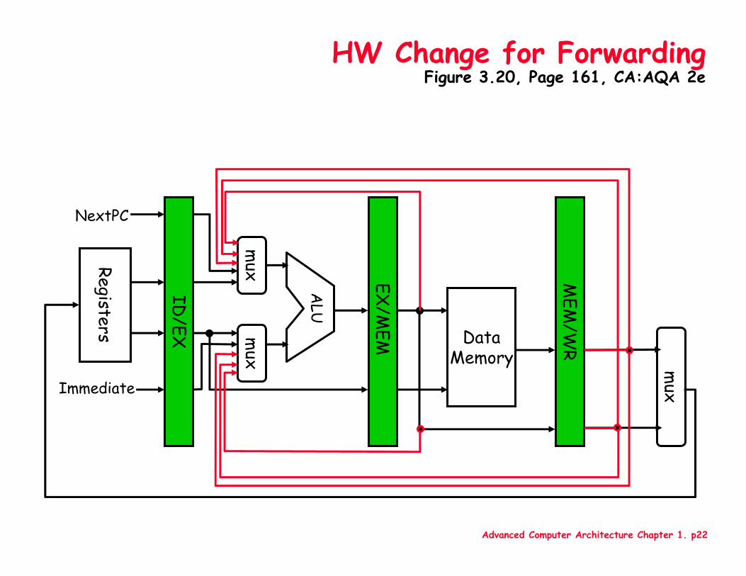
HW Change for ForwardingFigure 3.20, Page 161, CA:AQA 2e
MEM
/WR
ID/EX
EX/M
EM
DataMemory
ALU
mux
mux
Registers
NextPC
Immediate
mux
Advanced Computer Architecture Chapter 1. p23
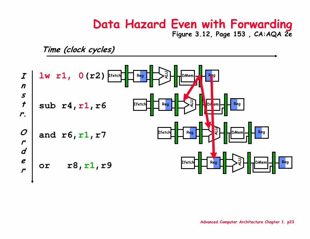
Time (clock cycles)
Instr.
Order
lw r1, 0(r2)
sub r4,r1,r6
and r6,r1,r7
or r8,r1,r9
Data Hazard Even with ForwardingFigure 3.12, Page 153 , CA:AQA 2e
Reg ALU DMemIfetch Reg
Reg ALU DMemIfetch Reg
Reg ALU DMemIfetch Reg
Reg ALU DMemIfetch Reg
Advanced Computer Architecture Chapter 1. p24
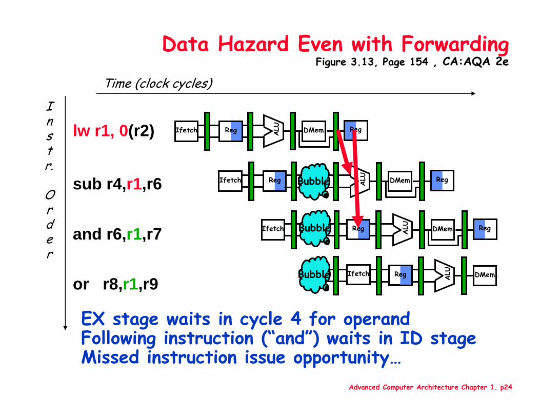
Data Hazard Even with ForwardingFigure 3.13, Page 154 , CA:AQA 2e
Time (clock cycles)
or r8,r1,r9
Instr.
Order
lw r1, 0(r2)
sub r4,r1,r6
and r6,r1,r7
Reg ALU DMemIfetch Reg
RegIfetch ALU DMem RegBubble
Ifetch ALU DMem RegBubble Reg
Ifetch ALU DMemBubble Reg
EX stage waits in cycle 4 for operandFollowing instruction (“and”) waits in ID stage Missed instruction issue opportunity…
Advanced Computer Architecture Chapter 1. p25
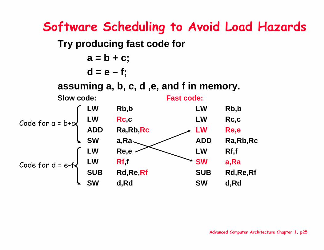
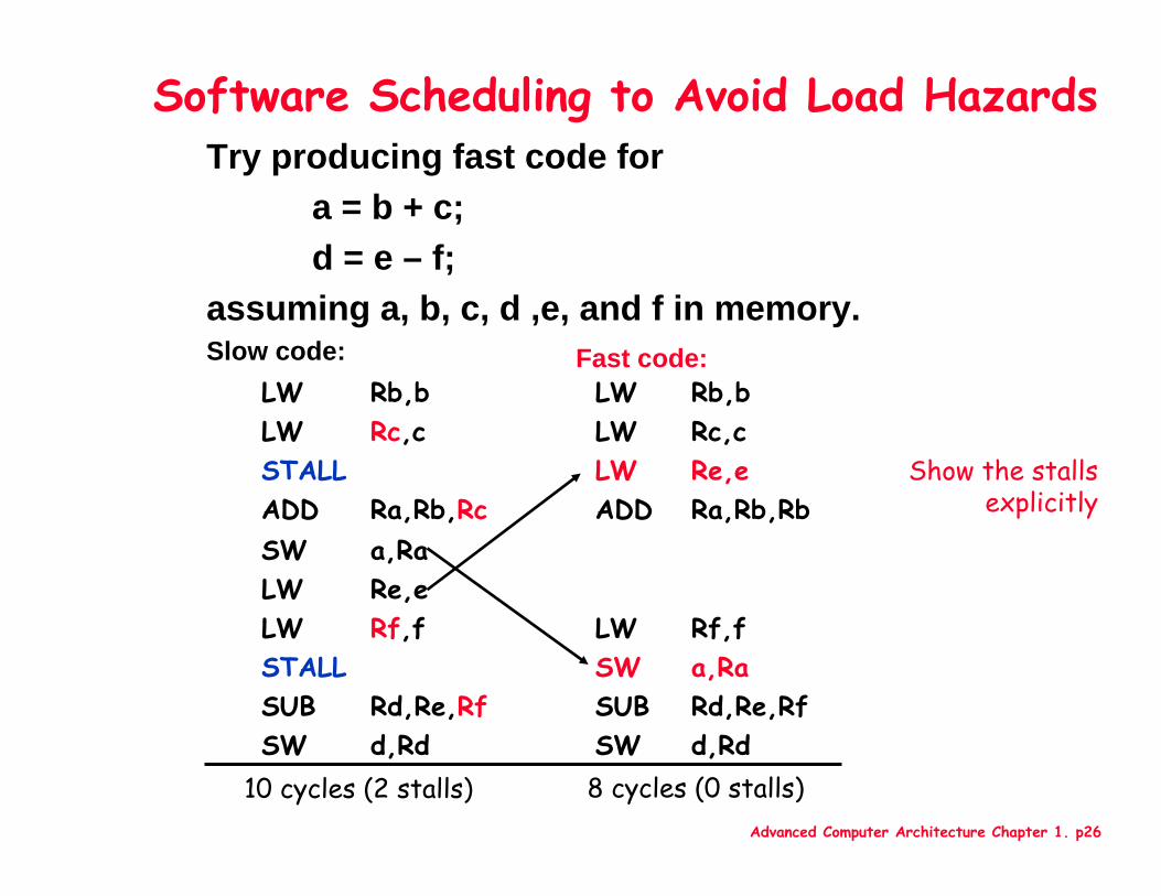
Try producing fast code fora = b + c;d = e – f;
assuming a, b, c, d ,e, and f in memory. Slow code:
LW Rb,bLW Rc,cADD Ra,Rb,RcSW a,Ra LW Re,e LW Rf,fSUB Rd,Re,RfSW d,Rd
Software Scheduling to Avoid Load Hazards
Fast code:LW Rb,bLW Rc,cLW Re,e ADD Ra,Rb,RcLW Rf,fSW a,Ra SUB Rd,Re,RfSW d,Rd
Code for d = e-f
Code for a = b+c
Advanced Computer Architecture Chapter 1. p26
Try producing fast code fora = b + c;d = e – f;
assuming a, b, c, d ,e, and f in memory. Slow code:
Software Scheduling to Avoid Load Hazards
Fast code:
d,RdSWd,RdSWRd,Re,RfSUBRd,Re,RfSUBa,RaSWSTALLRf,fLWRf,fLW
Re,eLWa,RaSW
Ra,Rb,RbADDRa,Rb,RcADDRe,eLWSTALLRc,cLWRc,cLWRb,bLWRb,bLW
10 cycles (2 stalls) 8 cycles (0 stalls)
Show the stalls explicitly
Advanced Computer Architecture Chapter 1. p27
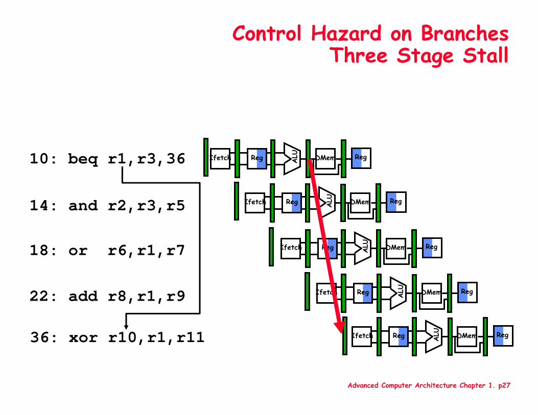
Control Hazard on BranchesThree Stage Stall
10: beq r1,r3,36
14: and r2,r3,r5
18: or r6,r1,r7
22: add r8,r1,r9
36: xor r10,r1,r11
Reg ALU DMemIfetch Reg
Reg ALU DMemIfetch Reg
Reg ALU DMemIfetch Reg
Reg ALU DMemIfetch Reg
Reg ALU DMemIfetch Reg
Advanced Computer Architecture Chapter 1. p28
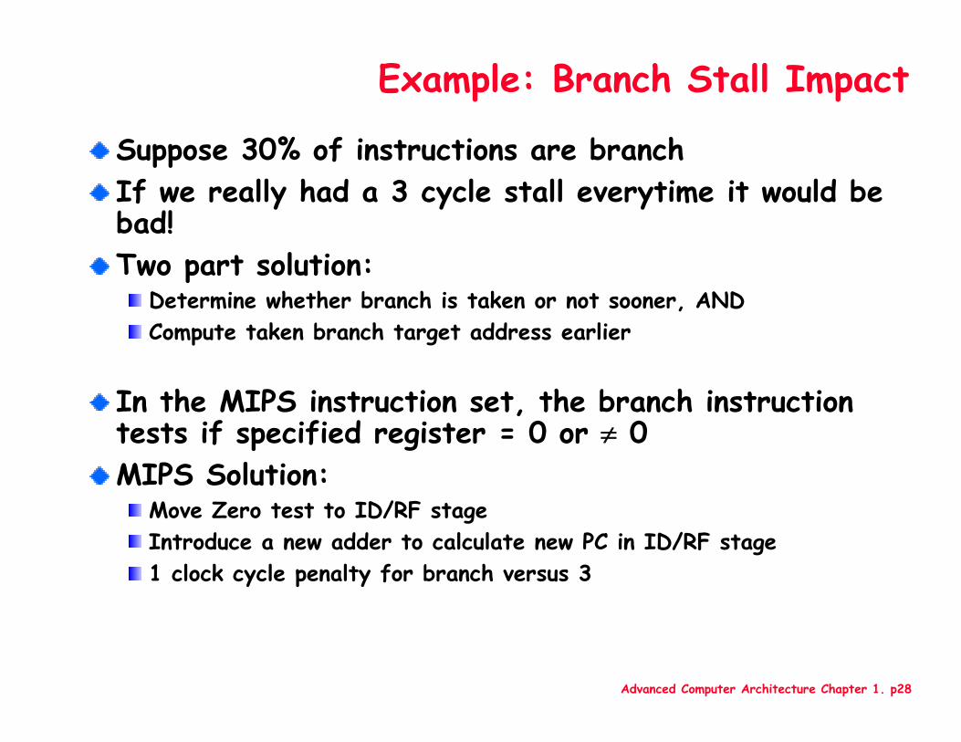
Example: Branch Stall Impact
Suppose 30% of instructions are branchIf we really had a 3 cycle stall everytime it would be bad!Two part solution:
Determine whether branch is taken or not sooner, ANDCompute taken branch target address earlier
In the MIPS instruction set, the branch instruction tests if specified register = 0 or ≠ 0MIPS Solution:
Move Zero test to ID/RF stageIntroduce a new adder to calculate new PC in ID/RF stage1 clock cycle penalty for branch versus 3
Advanced Computer Architecture Chapter 1. p29
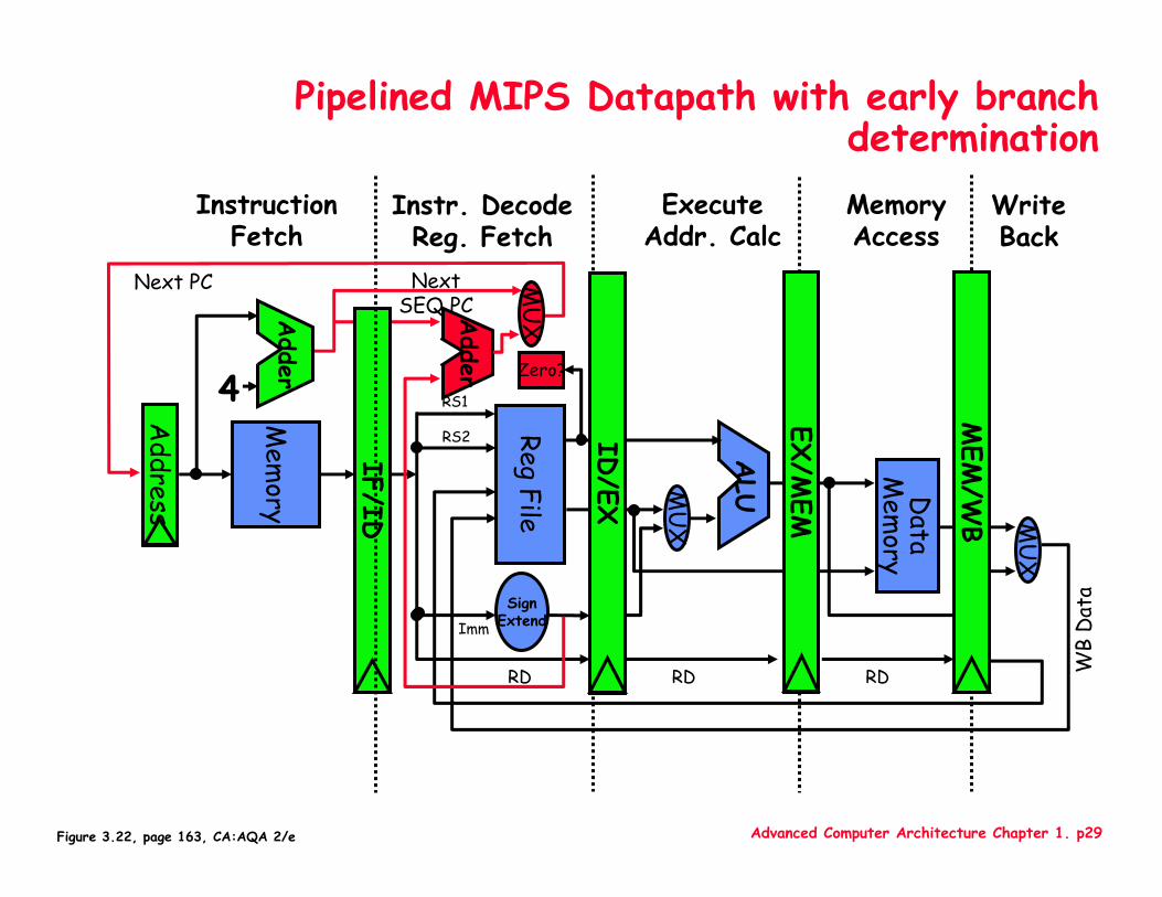
Adder
IF/ID
Pipelined MIPS Datapath with early branch determinationMemoryAccess
WriteBack
InstructionFetch
Instr. DecodeReg. Fetch
ExecuteAddr. Calc
ALU
Mem
ory
RegFile
MU
X
Data
Mem
ory
MU
X
SignExtend
Zero?
MEM
/WB
EX/M
EM4
Adder
Next SEQ PC
RD RD RD WB
Dat
a
Next PC
Address
RS1
RS2
ImmM
UX
ID/EX
Figure 3.22, page 163, CA:AQA 2/e
Advanced Computer Architecture Chapter 1. p30
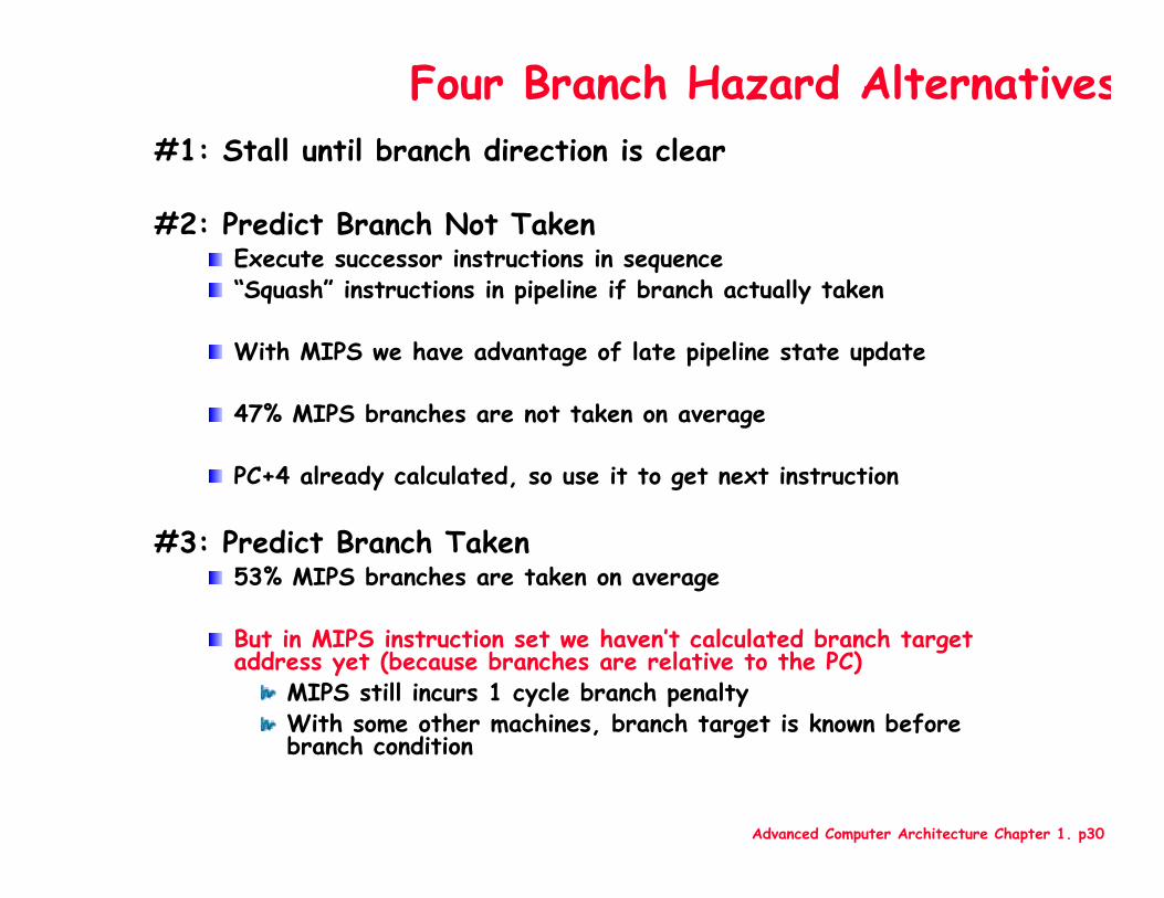
Four Branch Hazard Alternatives#1: Stall until branch direction is clear
#2: Predict Branch Not TakenExecute successor instructions in sequence“Squash” instructions in pipeline if branch actually taken
With MIPS we have advantage of late pipeline state update
47% MIPS branches are not taken on average
PC+4 already calculated, so use it to get next instruction
#3: Predict Branch Taken53% MIPS branches are taken on average
But in MIPS instruction set we haven’t calculated branch target address yet (because branches are relative to the PC)
MIPS still incurs 1 cycle branch penaltyWith some other machines, branch target is known before branch condition
Advanced Computer Architecture Chapter 1. p31
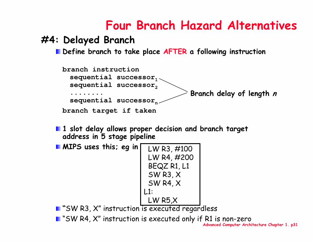
Four Branch Hazard Alternatives#4: Delayed Branch
Define branch to take place AFTER a following instruction
branch instructionsequential successor1sequential successor2........sequential successorn
branch target if taken
1 slot delay allows proper decision and branch target address in 5 stage pipelineMIPS uses this; eg in
“SW R3, X” instruction is executed regardless“SW R4, X” instruction is executed only if R1 is non-zero
Branch delay of length n
LW R3, #100LW R4, #200BEQZ R1, L1SW R3, XSW R4, X
L1:LW R5,X
Advanced Computer Architecture Chapter 1. p32
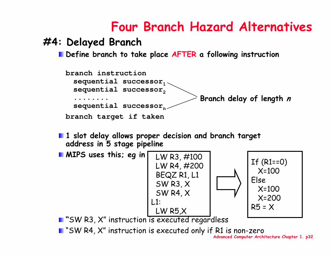
Four Branch Hazard Alternatives#4: Delayed Branch
Define branch to take place AFTER a following instruction
branch instructionsequential successor1sequential successor2........sequential successorn
branch target if taken
1 slot delay allows proper decision and branch target address in 5 stage pipelineMIPS uses this; eg in
“SW R3, X” instruction is executed regardless“SW R4, X” instruction is executed only if R1 is non-zero
Branch delay of length n
LW R3, #100LW R4, #200BEQZ R1, L1SW R3, XSW R4, X
L1:LW R5,X
If (R1==0) X=100
ElseX=100X=200
R5 = X
Advanced Computer Architecture Chapter 1. p33
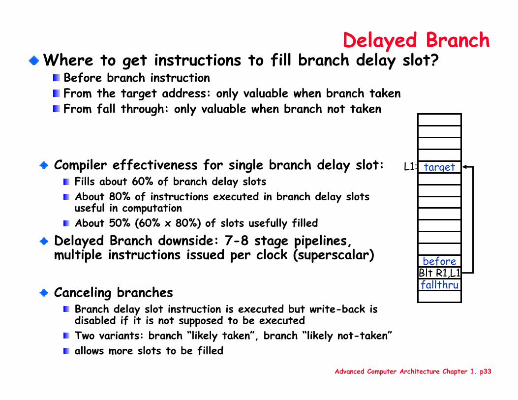
Delayed BranchWhere to get instructions to fill branch delay slot?
Before branch instructionFrom the target address: only valuable when branch takenFrom fall through: only valuable when branch not taken
target
beforeBlt R1,L1fallthru
L1:Compiler effectiveness for single branch delay slot:Fills about 60% of branch delay slotsAbout 80% of instructions executed in branch delay slots useful in computationAbout 50% (60% x 80%) of slots usefully filled
Delayed Branch downside: 7-8 stage pipelines, multiple instructions issued per clock (superscalar)
Canceling branchesBranch delay slot instruction is executed but write-back is disabled if it is not supposed to be executedTwo variants: branch “likely taken”, branch “likely not-taken”allows more slots to be filled
Advanced Computer Architecture Chapter 1. p34
Now, Review of Memory Hierarchy
Advanced Computer Architecture Chapter 1. p35
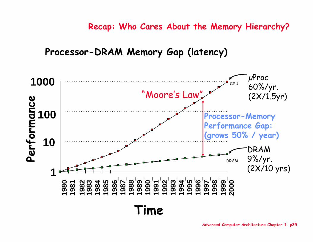
Recap: Who Cares About the Memory Hierarchy?
µProc60%/yr.(2X/1.5yr)
DRAM9%/yr.(2X/10 yrs)1
10
100
100019
8019
81
1983
1984
1985
1986
1987
1988
1989
1990
1991
1992
1993
1994
1995
1996
1997
1998
1999
2000
DRAM
CPU19
82
Processor-MemoryPerformance Gap:(grows 50% / year)
Perf
orman
ce
Time
“Moore’s Law”
Processor-DRAM Memory Gap (latency)
Advanced Computer Architecture Chapter 1. p36
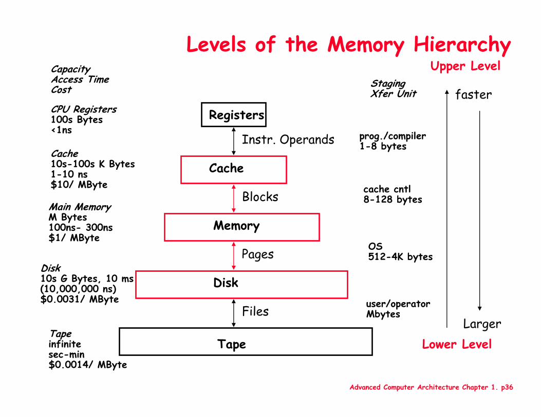
Levels of the Memory Hierarchy
CPU Registers100s Bytes<1ns
Cache10s-100s K Bytes1-10 ns$10/ MByte
Main MemoryM Bytes100ns- 300ns$1/ MByte
Disk10s G Bytes, 10 ms (10,000,000 ns)$0.0031/ MByte
CapacityAccess TimeCost
Tapeinfinitesec-min$0.0014/ MByte
Registers
Cache
Memory
Disk
Tape
Instr. Operands
Blocks
Pages
Files
StagingXfer Unit
prog./compiler1-8 bytes
cache cntl8-128 bytes
OS512-4K bytes
user/operatorMbytes
Upper Level
Lower Level
faster
Larger
Advanced Computer Architecture Chapter 1. p37
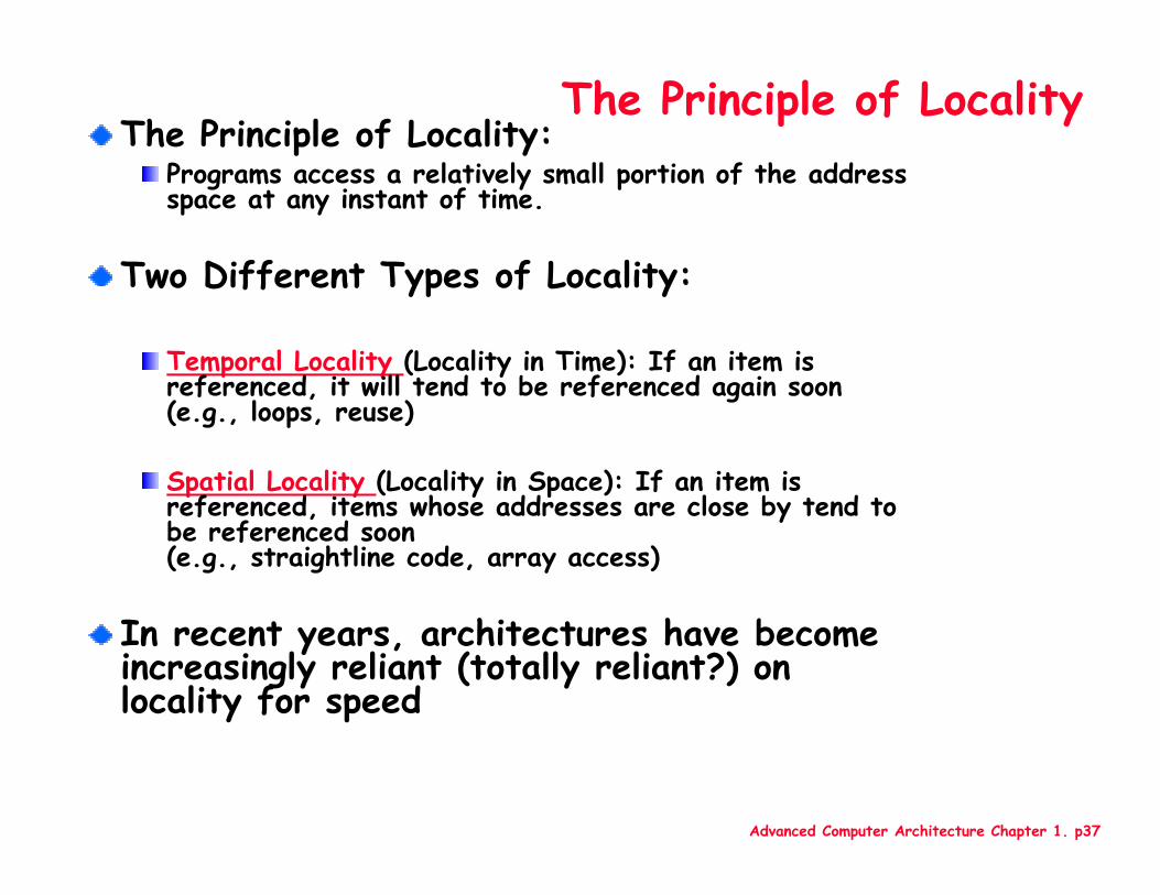
The Principle of LocalityThe Principle of Locality:
Programs access a relatively small portion of the address space at any instant of time.
Two Different Types of Locality:
Temporal Locality (Locality in Time): If an item is referenced, it will tend to be referenced again soon (e.g., loops, reuse)
Spatial Locality (Locality in Space): If an item is referenced, items whose addresses are close by tend to be referenced soon (e.g., straightline code, array access)
In recent years, architectures have become increasingly reliant (totally reliant?) on locality for speed
Advanced Computer Architecture Chapter 1. p38
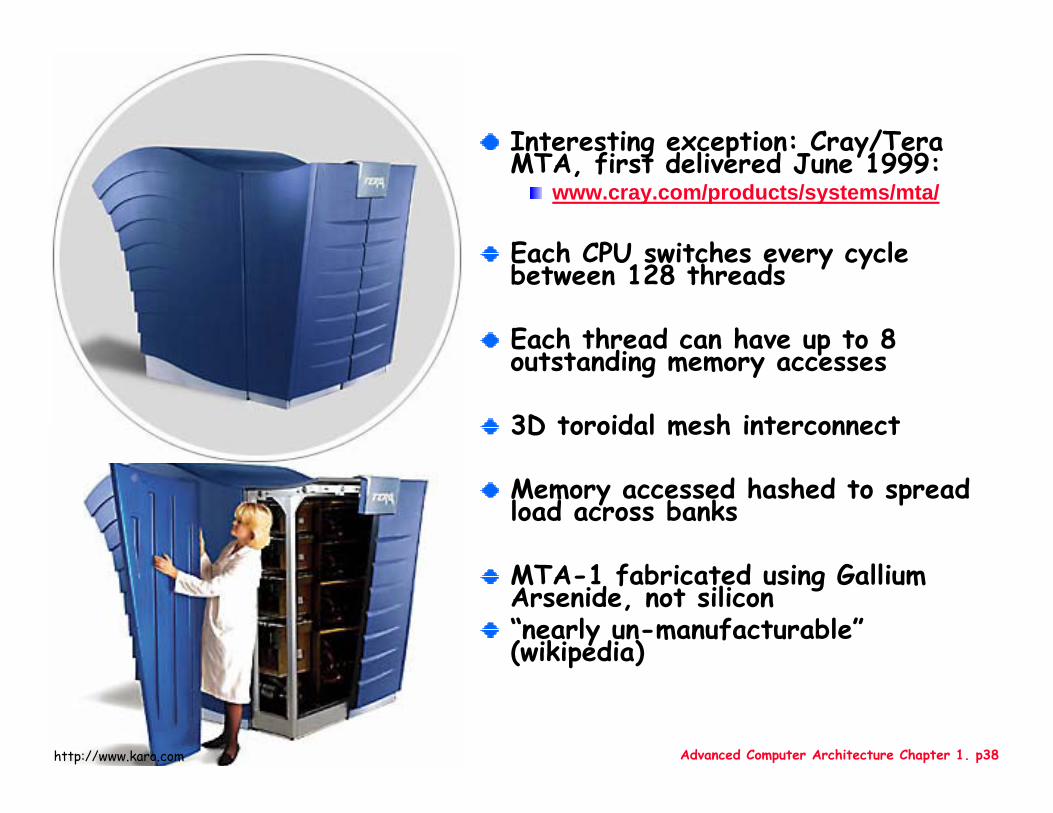
Interesting exception: Cray/TeraMTA, first delivered June 1999:
www.cray.com/products/systems/mta/
Each CPU switches every cycle between 128 threads
Each thread can have up to 8 outstanding memory accesses
3D toroidal mesh interconnect
Memory accessed hashed to spread load across banks
MTA-1 fabricated using Gallium Arsenide, not silicon“nearly un-manufacturable”(wikipedia)
http://www.karo.com
Advanced Computer Architecture Chapter 1. p39
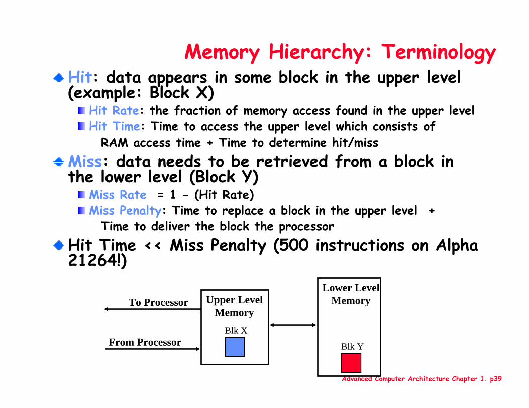
Memory Hierarchy: TerminologyHit: data appears in some block in the upper level (example: Block X)
Hit Rate: the fraction of memory access found in the upper levelHit Time: Time to access the upper level which consists of
RAM access time + Time to determine hit/missMiss: data needs to be retrieved from a block in the lower level (Block Y)
Miss Rate = 1 - (Hit Rate)Miss Penalty: Time to replace a block in the upper level +
Time to deliver the block the processorHit Time << Miss Penalty (500 instructions on Alpha 21264!)
Lower LevelMemoryUpper Level
MemoryTo Processor
From ProcessorBlk X
Blk Y
Advanced Computer Architecture Chapter 1. p40
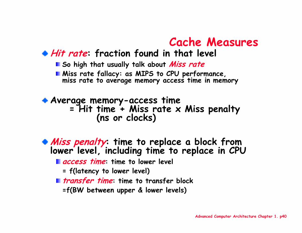
Cache MeasuresHit rate: fraction found in that level
So high that usually talk about Miss rateMiss rate fallacy: as MIPS to CPU performance, miss rate to average memory access time in memory
Average memory-access time = Hit time + Miss rate x Miss penalty
(ns or clocks)
Miss penalty: time to replace a block from lower level, including time to replace in CPU
access time: time to lower level = f(latency to lower level)transfer time: time to transfer block =f(BW between upper & lower levels)
Advanced Computer Architecture Chapter 1. p41
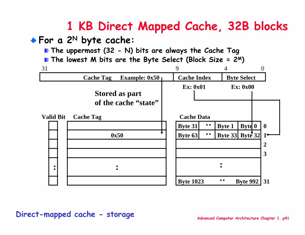
1 KB Direct Mapped Cache, 32B blocksFor a 2N byte cache:
The uppermost (32 - N) bits are always the Cache TagThe lowest M bits are the Byte Select (Block Size = 2M)
Cache Index
0123
:
Cache DataByte 0
0431
:
Cache Tag Example: 0x50Ex: 0x01
0x50
Stored as partof the cache “state”
Valid Bit
:31
Byte 1Byte 31 :
Byte 32Byte 33Byte 63 :
Byte 992Byte 1023 :
Cache Tag
Byte SelectEx: 0x00
9
Direct-mapped cache - storage
Advanced Computer Architecture Chapter 1. p42
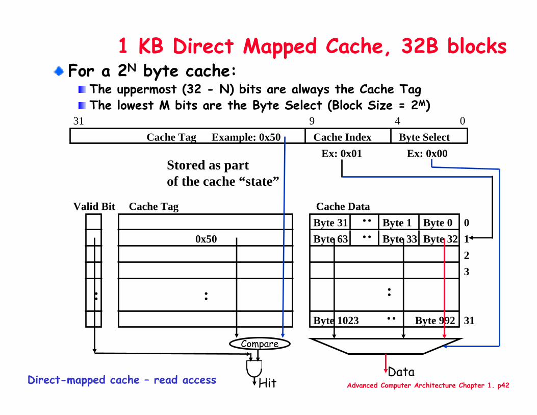
1 KB Direct Mapped Cache, 32B blocksFor a 2N byte cache:
The uppermost (32 - N) bits are always the Cache TagThe lowest M bits are the Byte Select (Block Size = 2M)
Cache Index
0123
:
Cache DataByte 0
0431
:
Cache Tag Example: 0x50Ex: 0x01
0x50
Stored as partof the cache “state”
Valid Bit
:31
Byte 1Byte 31 :
Byte 32Byte 33Byte 63 :
Byte 992Byte 1023 :
Cache Tag
Byte SelectEx: 0x00
9
Compare
HitDirect-mapped cache – read accessData
Advanced Computer Architecture Chapter 1. p43
1 KB Direct Mapped Cache, 32B blocks
0123
:
Cache DataByte 0
31
Byte 1Byte 31 :
Byte 32Byte 33Byte 63 :Byte 992Byte 1023 :
6
7
8
9
10
11
12
13
32
31
30
29
28
27
26
25
24
23
22
21
20
19
18
17
16
15
14
5
4
3
2
1
0
35
34
33
Main Memory
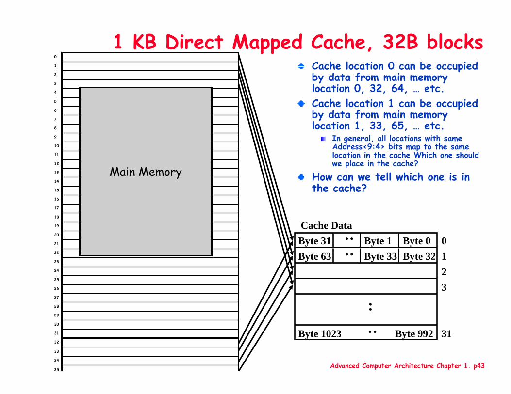
Cache location 0 can be occupied by data from main memory location 0, 32, 64, … etc.Cache location 1 can be occupied by data from main memory location 1, 33, 65, … etc.
In general, all locations with same Address<9:4> bits map to the same location in the cache Which one should we place in the cache?
How can we tell which one is in the cache?
Advanced Computer Architecture Chapter 1. p44
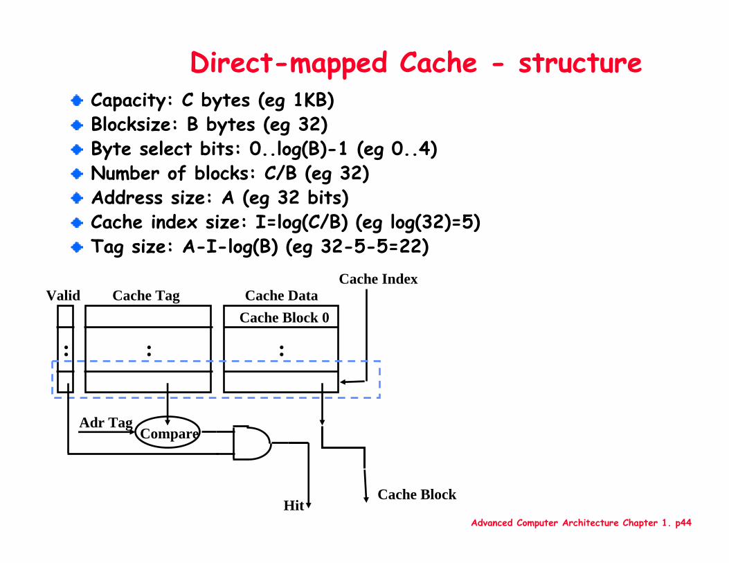
Direct-mapped Cache - structureCapacity: C bytes (eg 1KB)Blocksize: B bytes (eg 32)Byte select bits: 0..log(B)-1 (eg 0..4)Number of blocks: C/B (eg 32)Address size: A (eg 32 bits)Cache index size: I=log(C/B) (eg log(32)=5)Tag size: A-I-log(B) (eg 32-5-5=22)
Cache DataCache Block 0
Cache TagValid
:: :
Cache Index
Cache Block
CompareAdr Tag
Hit
Advanced Computer Architecture Chapter 1. p45
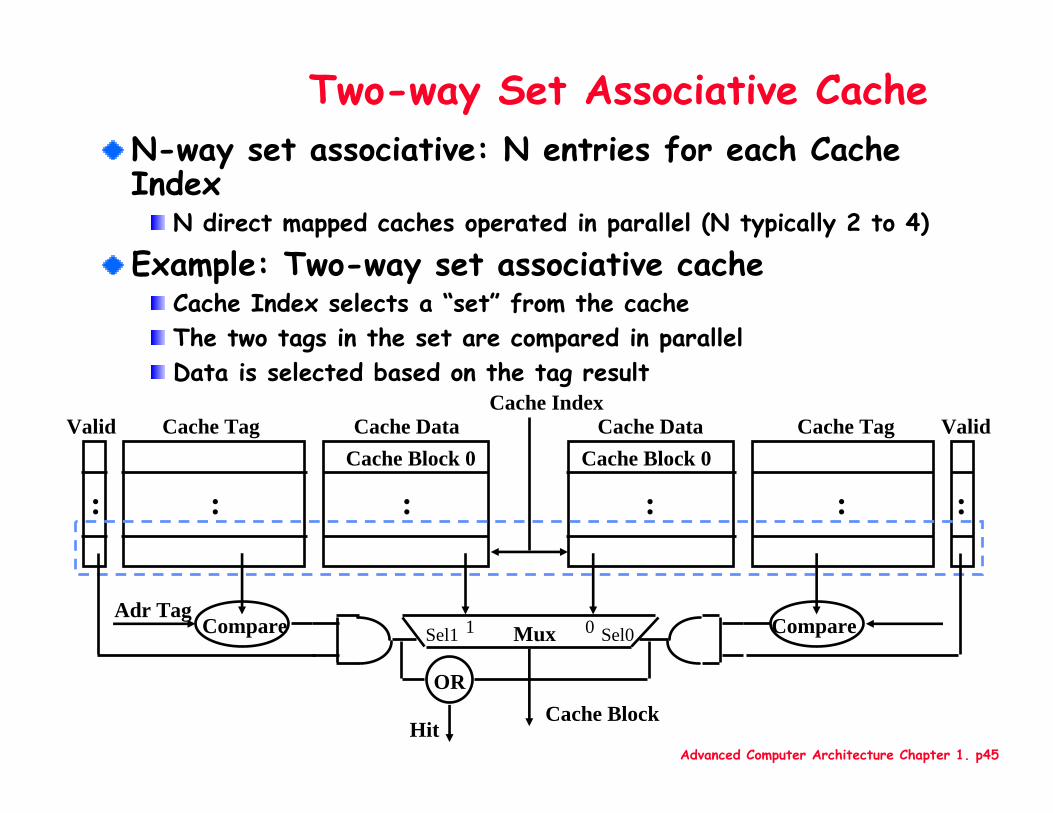
Two-way Set Associative CacheN-way set associative: N entries for each Cache Index
N direct mapped caches operated in parallel (N typically 2 to 4)
Example: Two-way set associative cacheCache Index selects a “set” from the cacheThe two tags in the set are compared in parallelData is selected based on the tag result
Cache DataCache Block 0
Cache TagValid
:: :
Cache DataCache Block 0
Cache Tag Valid
: ::
Cache Index
Mux 01Sel1 Sel0
Cache Block
CompareAdr Tag
Compare
OR
Hit
Advanced Computer Architecture Chapter 1. p46
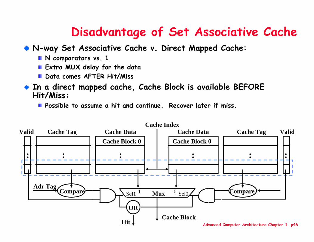
Disadvantage of Set Associative CacheN-way Set Associative Cache v. Direct Mapped Cache:
N comparators vs. 1Extra MUX delay for the dataData comes AFTER Hit/Miss
In a direct mapped cache, Cache Block is available BEFORE Hit/Miss:
Possible to assume a hit and continue. Recover later if miss.
Cache DataCache Block 0
Cache Tag Valid
: ::
Cache DataCache Block 0
Cache TagValid
:: :
Cache Index
Mux 01Sel1 Sel0
Cache Block
CompareAdr Tag
Compare
OR
Hit
Advanced Computer Architecture Chapter 1. p47
Basic cache terminology
Cache DataCache Block 0
Cache Tag Valid
: ::
Cache DataCache Block 0
Cache TagValid
:: :
Cache Index
Mux 01Sel1 Sel0
Cache Block
CompareAdr Tag
Compare
OR
Hit
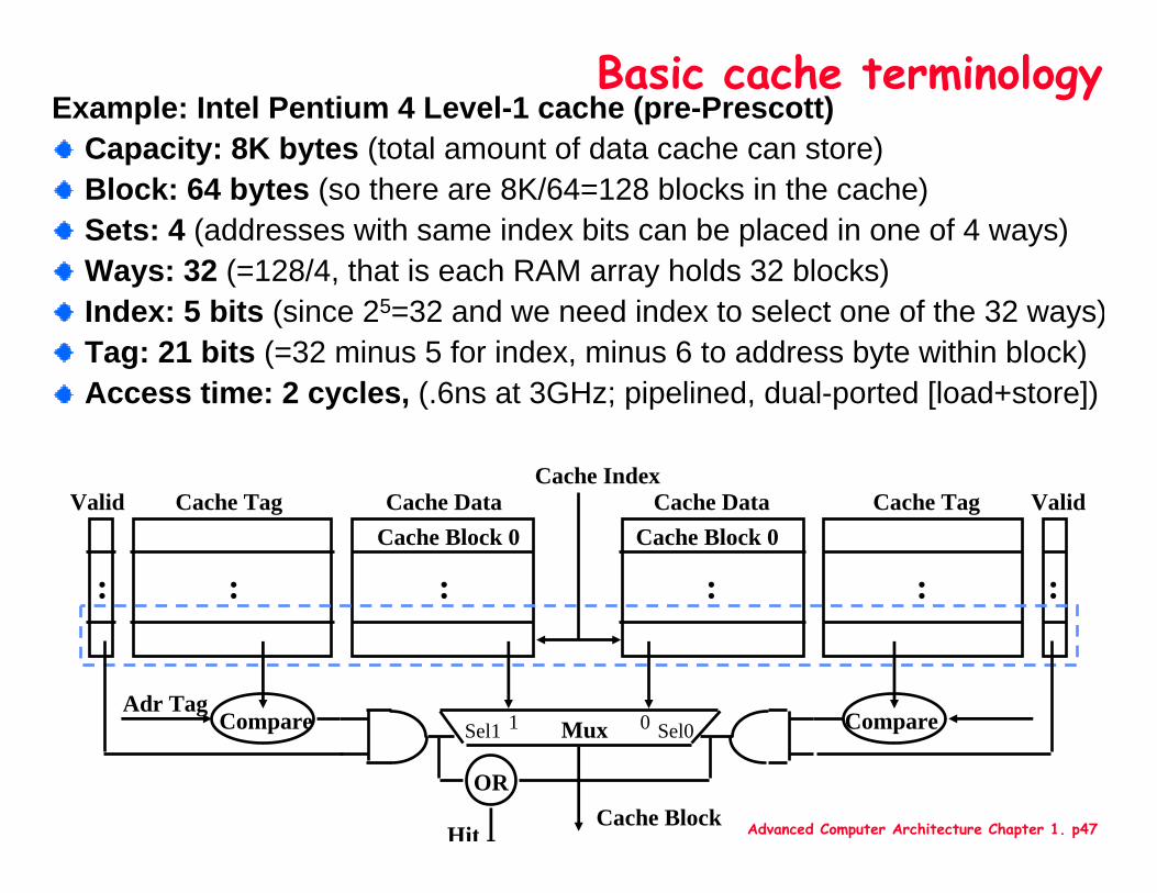
Example: Intel Pentium 4 Level-1 cache (pre-Prescott)Capacity: 8K bytes (total amount of data cache can store)Block: 64 bytes (so there are 8K/64=128 blocks in the cache)Sets: 4 (addresses with same index bits can be placed in one of 4 ways)Ways: 32 (=128/4, that is each RAM array holds 32 blocks)Index: 5 bits (since 25=32 and we need index to select one of the 32 ways)Tag: 21 bits (=32 minus 5 for index, minus 6 to address byte within block)Access time: 2 cycles, (.6ns at 3GHz; pipelined, dual-ported [load+store])
Advanced Computer Architecture Chapter 1. p48
4 Questions for Memory Hierarchy
Q1: Where can a block be placed in the upper level? (Block placement)
Q2: How is a block found if it is in the upper level?(Block identification)
Q3: Which block should be replaced on a miss? (Block replacement)
Q4: What happens on a write? (Write strategy)
Advanced Computer Architecture Chapter 1. p49
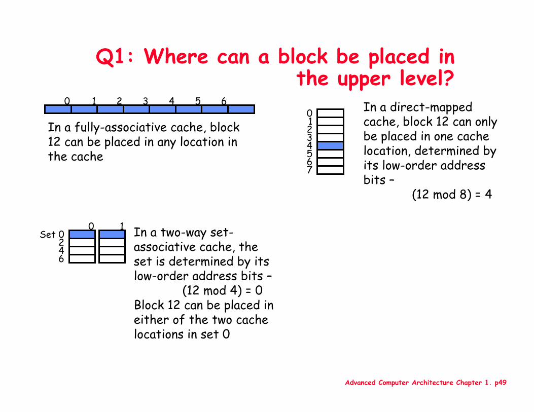
Q1: Where can a block be placed in the upper level?
0 1 2 3 4 5 601234567
Set 0246
0 1
In a fully-associative cache, block 12 can be placed in any location in the cache
In a direct-mapped cache, block 12 can only be placed in one cache location, determined by its low-order address bits –
(12 mod 8) = 4
In a two-way set-associative cache, the set is determined by its low-order address bits –
(12 mod 4) = 0Block 12 can be placed in either of the two cache locations in set 0
Advanced Computer Architecture Chapter 1. p50
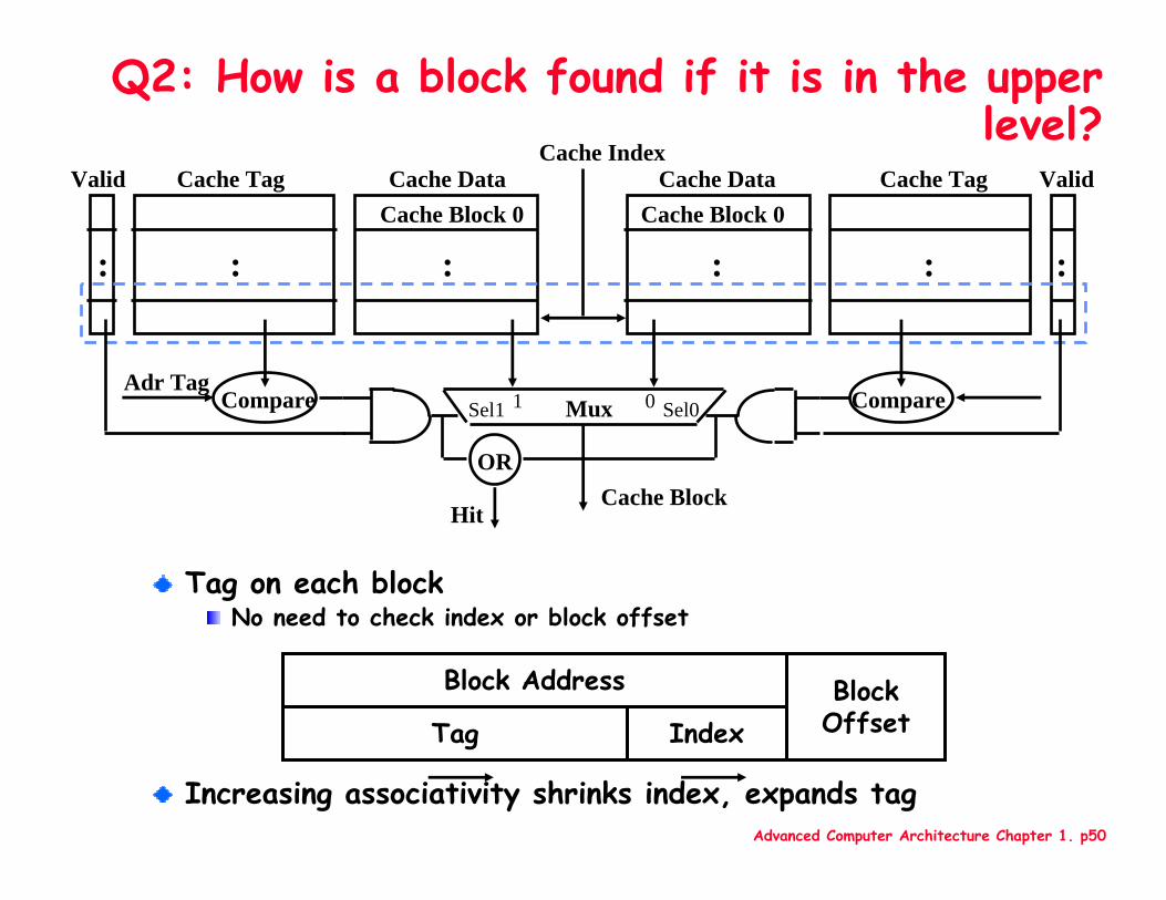
Q2: How is a block found if it is in the upper level?
Tag on each blockNo need to check index or block offset
Increasing associativity shrinks index, expands tag
BlockOffset
Block Address
IndexTag
Cache DataCache Block 0
Cache Tag Valid
: ::
Cache DataCache Block 0
Cache TagValid
:: :
Cache Index
Mux 01Sel1 Sel0
Cache Block
CompareAdr Tag
Compare
OR
Hit
Advanced Computer Architecture Chapter 1. p51
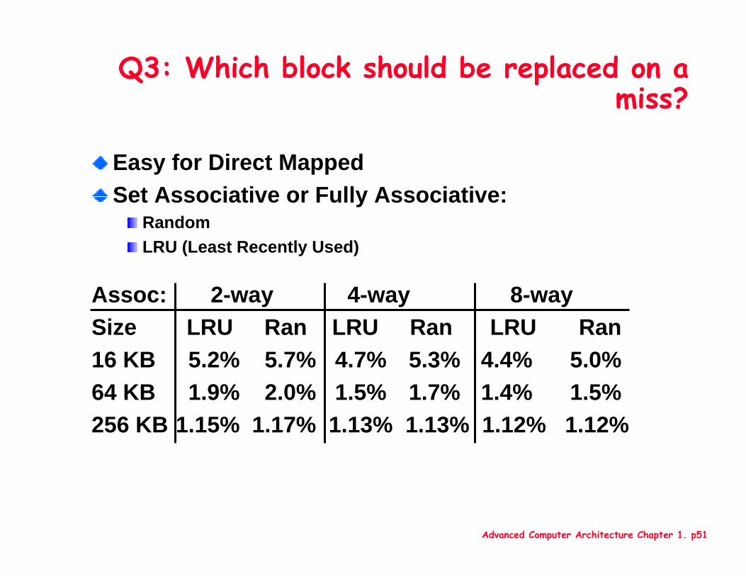
Q3: Which block should be replaced on a miss?
Easy for Direct MappedSet Associative or Fully Associative:
RandomLRU (Least Recently Used)
Assoc: 2-way 4-way 8-waySize LRU Ran LRU Ran LRU Ran16 KB 5.2% 5.7% 4.7% 5.3% 4.4% 5.0%64 KB 1.9% 2.0% 1.5% 1.7% 1.4% 1.5%256 KB 1.15% 1.17% 1.13% 1.13% 1.12% 1.12%
Advanced Computer Architecture Chapter 1. p52
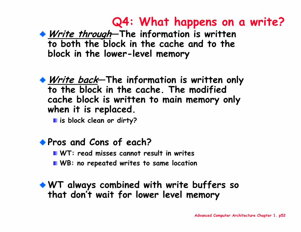
Q4: What happens on a write?Write through—The information is written to both the block in the cache and to the block in the lower-level memory
Write back—The information is written only to the block in the cache. The modified cache block is written to main memory only when it is replaced.
is block clean or dirty?
Pros and Cons of each?WT: read misses cannot result in writesWB: no repeated writes to same location
WT always combined with write buffers so that don’t wait for lower level memory
Advanced Computer Architecture Chapter 1. p53
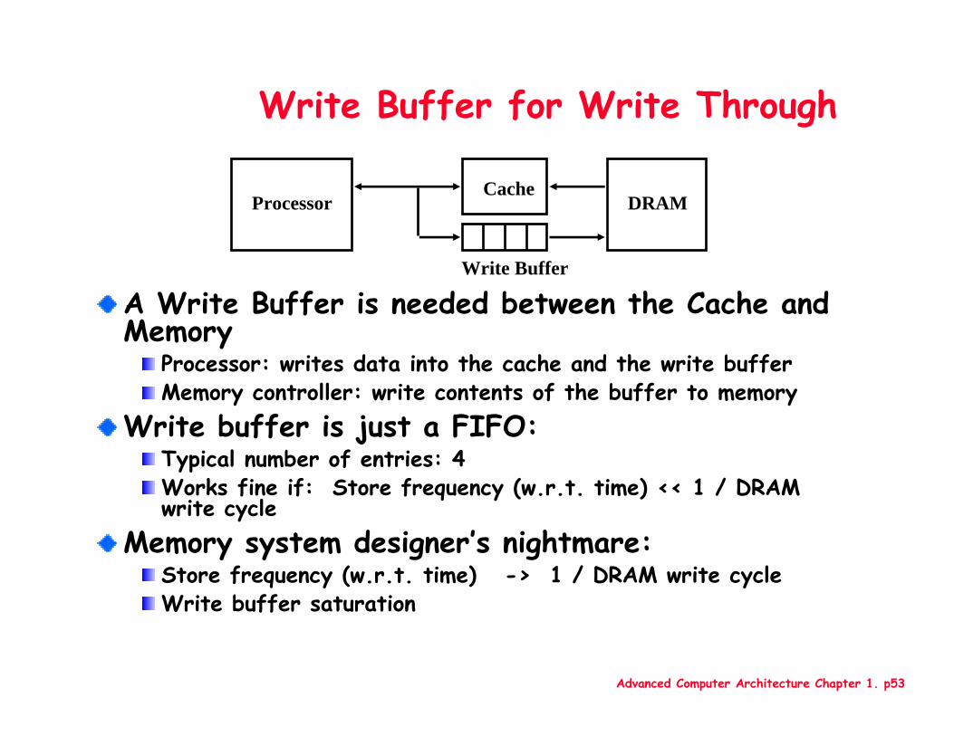
Write Buffer for Write Through
A Write Buffer is needed between the Cache and Memory
Processor: writes data into the cache and the write bufferMemory controller: write contents of the buffer to memory
Write buffer is just a FIFO:Typical number of entries: 4Works fine if: Store frequency (w.r.t. time) << 1 / DRAM write cycle
Memory system designer’s nightmare:Store frequency (w.r.t. time) -> 1 / DRAM write cycleWrite buffer saturation
ProcessorCache
Write Buffer
DRAM
Advanced Computer Architecture Chapter 1. p54
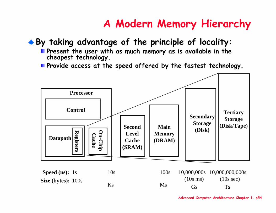
A Modern Memory HierarchyBy taking advantage of the principle of locality:
Present the user with as much memory as is available in the cheapest technology.Provide access at the speed offered by the fastest technology.
Control
Datapath
SecondaryStorage(Disk)
Processor
Registers
MainMemory(DRAM)
SecondLevelCache
(SRAM)
On-C
hipC
ache
1s 10,000,000s (10s ms)
Speed (ns): 10s 100s100s
GsSize (bytes):
Ks Ms
TertiaryStorage
(Disk/Tape)
10,000,000,000s (10s sec)
Ts
Advanced Computer Architecture Chapter 1. p55
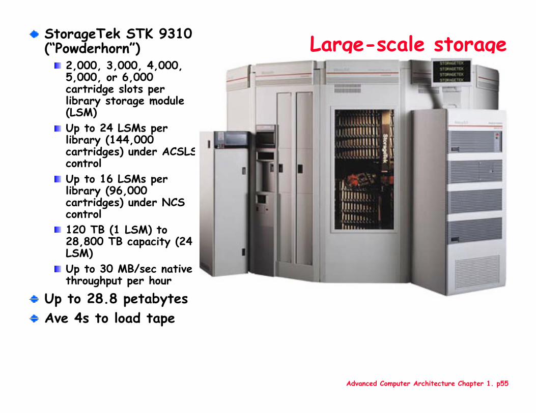
Large-scale storageStorageTek STK 9310 (“Powderhorn”)
2,000, 3,000, 4,000, 5,000, or 6,000 cartridge slots per library storage module (LSM)Up to 24 LSMs per library (144,000 cartridges) under ACSLS controlUp to 16 LSMs per library (96,000 cartridges) under NCS control120 TB (1 LSM) to 28,800 TB capacity (24 LSM)Up to 30 MB/sec native throughput per hour
Up to 28.8 petabytesAve 4s to load tape
Advanced Computer Architecture Chapter 1. p56
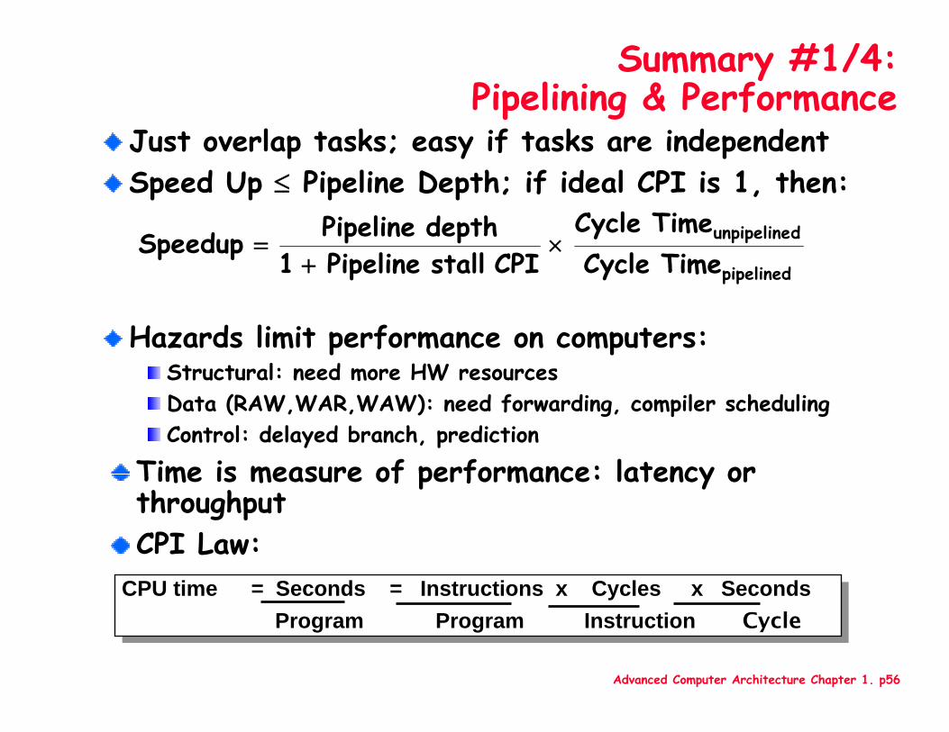
Summary #1/4: Pipelining & Performance
Just overlap tasks; easy if tasks are independentSpeed Up ≤ Pipeline Depth; if ideal CPI is 1, then:
Hazards limit performance on computers:Structural: need more HW resourcesData (RAW,WAR,WAW): need forwarding, compiler schedulingControl: delayed branch, prediction
pipelined
dunpipeline
TimeCycle TimeCycle
CPI stall Pipeline 1
depth Pipeline Speedup ×+
=
CPU time = Seconds = Instructions x Cycles x SecondsProgram Program Instruction Cycle
CPU time = Seconds = Instructions x Cycles x SecondsProgram Program Instruction Cycle
Time is measure of performance: latency or throughputCPI Law:
Advanced Computer Architecture Chapter 1. p57
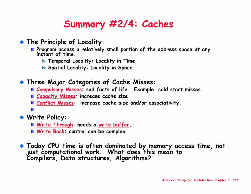
Summary #2/4: Caches
The Principle of Locality:Program access a relatively small portion of the address space at any instant of time.
Temporal Locality: Locality in TimeSpatial Locality: Locality in Space
Three Major Categories of Cache Misses:Compulsory Misses: sad facts of life. Example: cold start misses.Capacity Misses: increase cache sizeConflict Misses: increase cache size and/or associativity.
Write Policy:Write Through: needs a write buffer. Write Back: control can be complex
Today CPU time is often dominated by memory access time, not just computational work. What does this mean to Compilers, Data structures, Algorithms?

Advanced Computer Architecture Chapter 1. p58
Additional material
Advanced Computer Architecture Chapter 1. p59
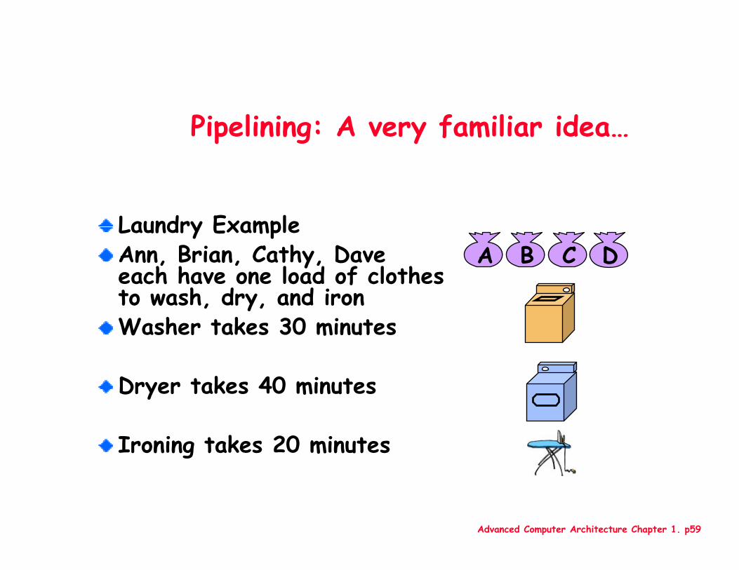
Pipelining: A very familiar idea…
Laundry ExampleAnn, Brian, Cathy, Dave each have one load of clothes to wash, dry, and ironWasher takes 30 minutes
Dryer takes 40 minutes
Ironing takes 20 minutes
A B C D
Advanced Computer Architecture Chapter 1. p60
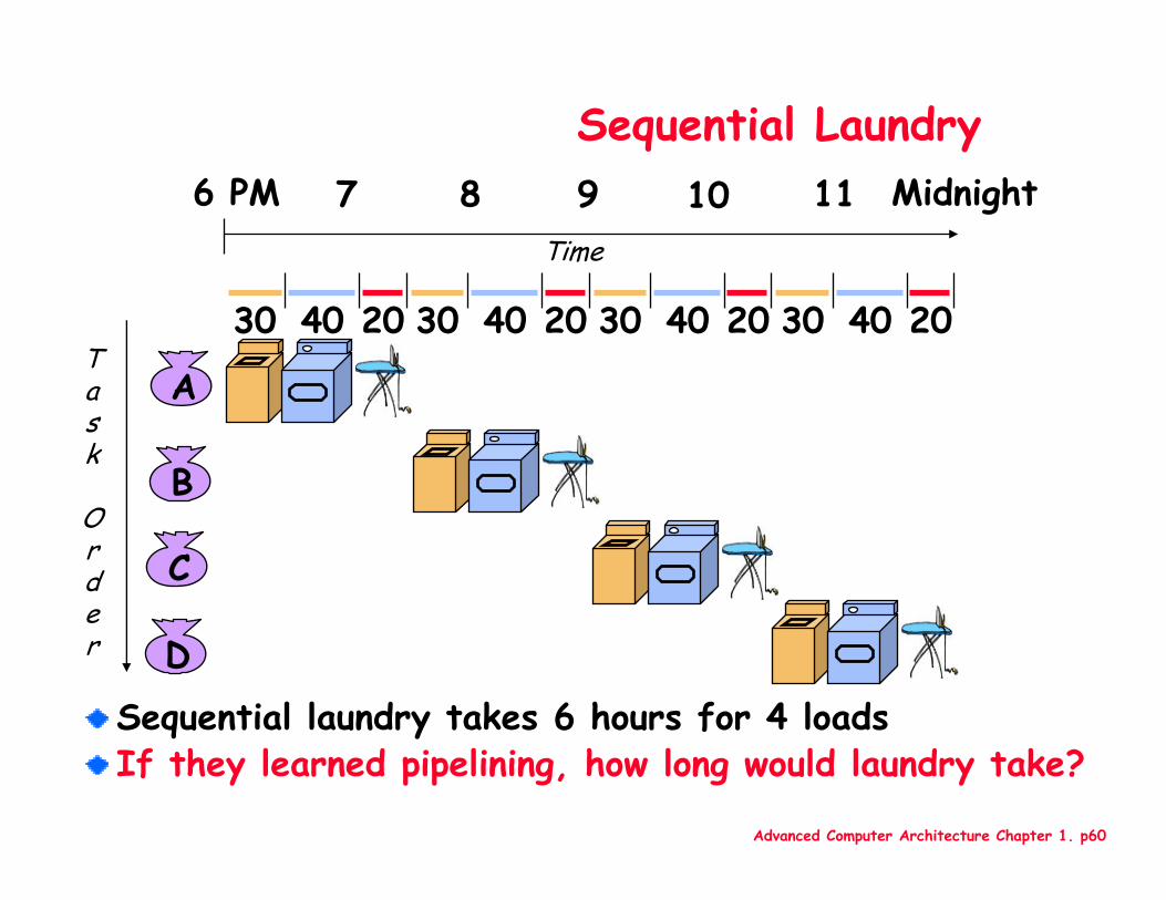
Sequential Laundry
Sequential laundry takes 6 hours for 4 loadsIf they learned pipelining, how long would laundry take?
A
B
C
D
30 40 20 30 40 20 30 40 20 30 40 20
6 PM 7 8 9 10 11 Midnight
Task
Order
Time
Advanced Computer Architecture Chapter 1. p61
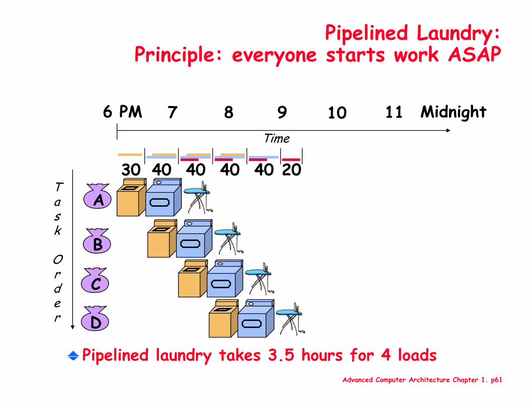
Pipelined Laundry:Principle: everyone starts work ASAP
Pipelined laundry takes 3.5 hours for 4 loads
A
B
C
D
6 PM 7 8 9 10 11 Midnight
Task
Order
Time
30 40 40 40 40 20
Advanced Computer Architecture Chapter 1. p62
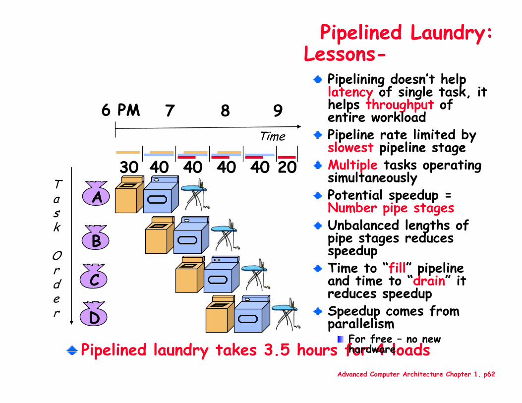
Pipelined Laundry:Lessons-
Pipelined laundry takes 3.5 hours for 4 loads
A
B
C
D
6 PM 7 8 9
Task
Order
Time
30 40 40 40 40 20
Pipelining doesn’t help latency of single task, it helps throughput of entire workloadPipeline rate limited by slowest pipeline stageMultiple tasks operating simultaneouslyPotential speedup = Number pipe stagesUnbalanced lengths of pipe stages reduces speedupTime to “fill” pipeline and time to “drain” it reduces speedupSpeedup comes from parallelism
For free – no new hardware
Advanced Computer Architecture Chapter 1. p63
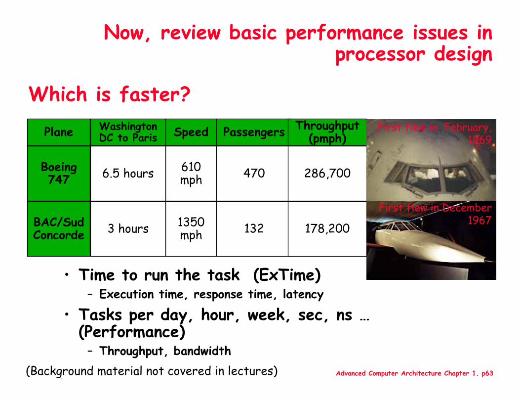
Which is faster?
• Time to run the task (ExTime)– Execution time, response time, latency
• Tasks per day, hour, week, sec, ns …(Performance)
– Throughput, bandwidth
Plane
Boeing 747
BAC/SudConcorde
Speed
610 mph
1350 mph
Washington DC to Paris
6.5 hours
3 hours
Passengers
470
132
Throughput (pmph)
286,700
178,200
First flew in December 1967
First flew in February, 1969
Now, review basic performance issues in processor design
(Background material not covered in lectures)
Advanced Computer Architecture Chapter 1. p64
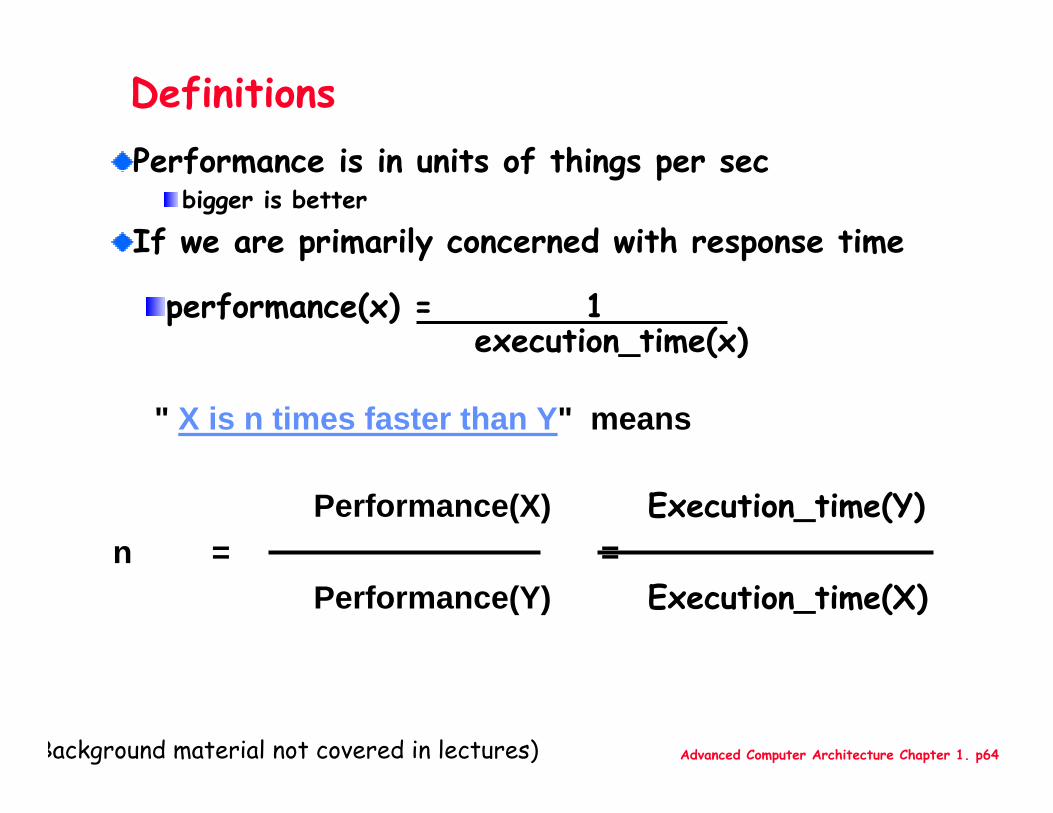
Performance(X) Execution_time(Y)n = =
Performance(Y) Execution_time(X)
DefinitionsPerformance is in units of things per sec
bigger is better
If we are primarily concerned with response time
performance(x) = 1 execution_time(x)
" X is n times faster than Y" means
Background material not covered in lectures)
Advanced Computer Architecture Chapter 1. p65
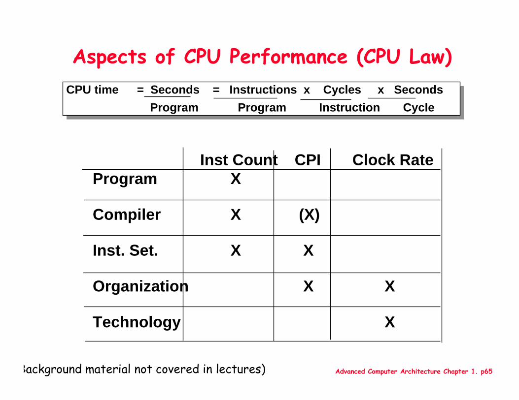
Aspects of CPU Performance (CPU Law)
CPU time = Seconds = Instructions x Cycles x SecondsProgram Program Instruction Cycle
CPU time = Seconds = Instructions x Cycles x SecondsProgram Program Instruction Cycle
Inst Count CPI Clock RateProgram X
Compiler X (X)
Inst. Set. X X
Organization X X
Technology X
Background material not covered in lectures)
Advanced Computer Architecture Chapter 1. p66
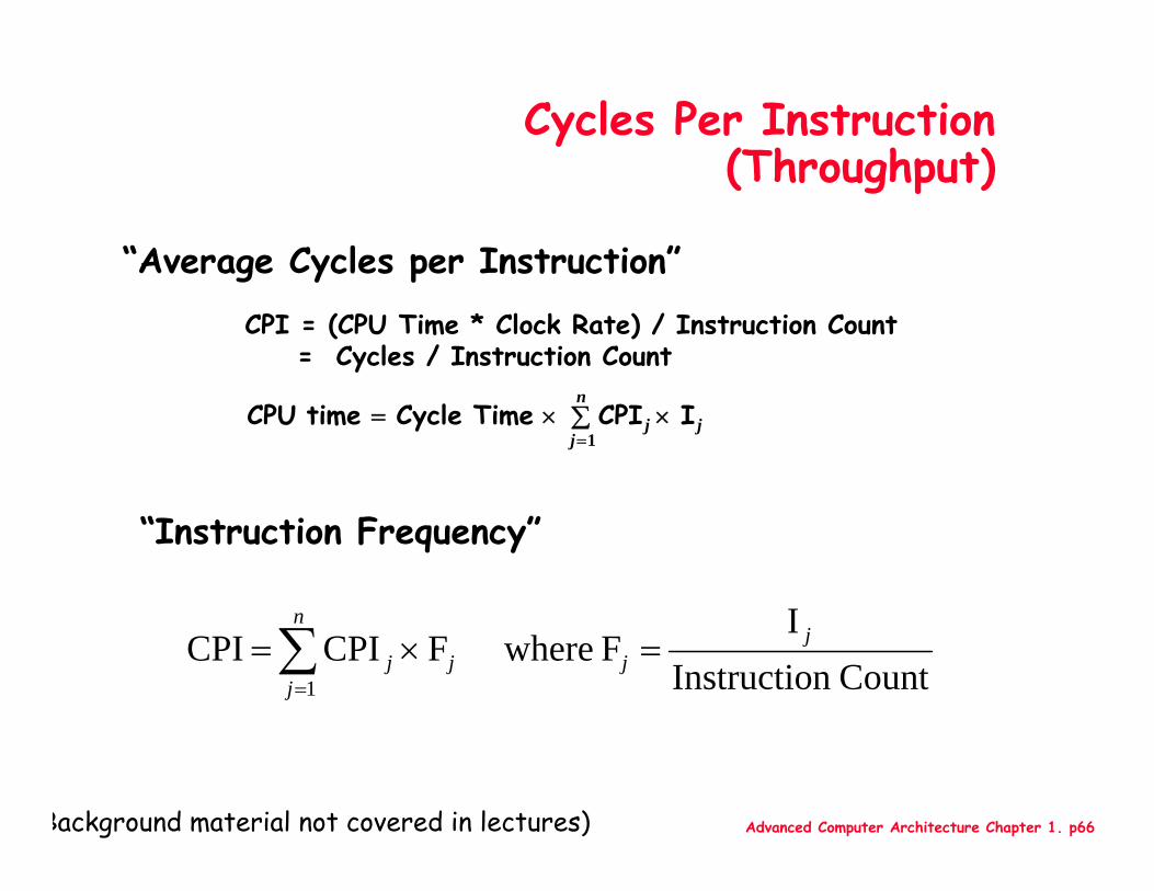
Cycles Per Instruction(Throughput)
“Instruction Frequency”
CPI = (CPU Time * Clock Rate) / Instruction Count = Cycles / Instruction Count
“Average Cycles per Instruction”
jn
jj I CPI TimeCycle time CPU ×∑×=
=1
Countn InstructioI
F whereF CPI CPI1
jj
n
jjj =×=∑
=
Background material not covered in lectures)
Advanced Computer Architecture Chapter 1. p67
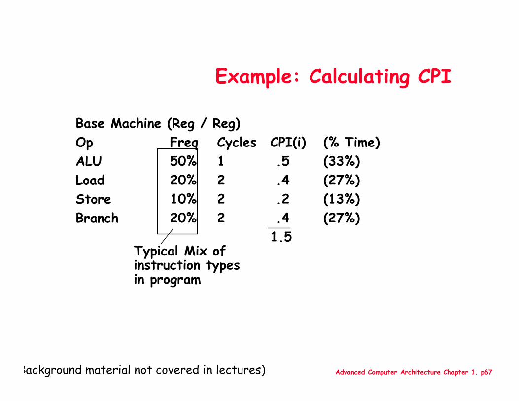
Example: Calculating CPI
Typical Mix of instruction typesin program
Base Machine (Reg / Reg)Op Freq Cycles CPI(i) (% Time)ALU 50% 1 .5 (33%)Load 20% 2 .4 (27%)Store 10% 2 .2 (13%)Branch 20% 2 .4 (27%)
1.5
Background material not covered in lectures)
Advanced Computer Architecture Chapter 1. p68
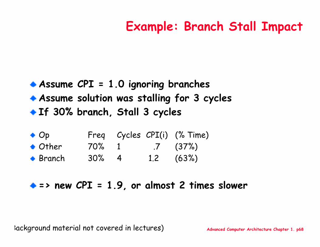
Example: Branch Stall Impact
Assume CPI = 1.0 ignoring branchesAssume solution was stalling for 3 cyclesIf 30% branch, Stall 3 cycles
Op Freq Cycles CPI(i) (% Time)Other 70% 1 .7 (37%)Branch 30% 4 1.2 (63%)
=> new CPI = 1.9, or almost 2 times slower
Background material not covered in lectures)
Advanced Computer Architecture Chapter 1. p69
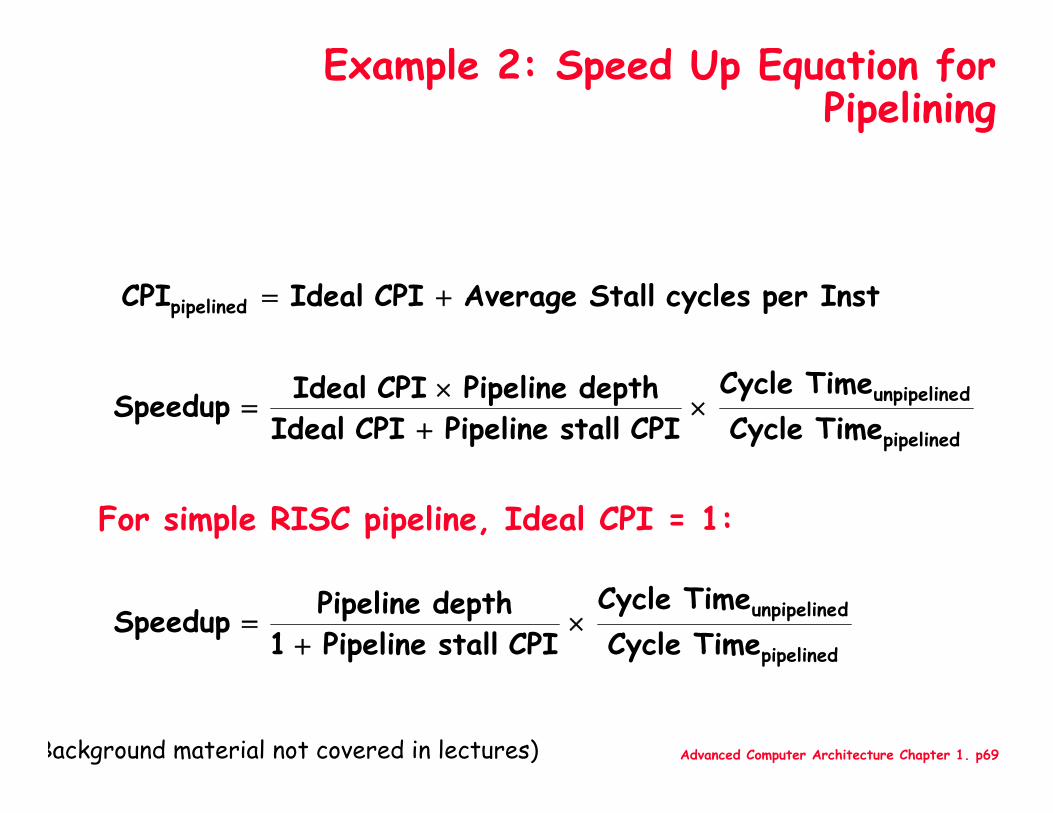
Example 2: Speed Up Equation for Pipelining
pipelined
dunpipeline
TimeCycle TimeCycle
CPI stall Pipeline CPI Ideal
depth Pipeline CPI Ideal Speedup ×+×
=
pipelined
dunpipeline
TimeCycle TimeCycle
CPI stall Pipeline 1
depth Pipeline Speedup ×+
=
Instper cycles Stall Average CPI Ideal CPIpipelined +=
For simple RISC pipeline, Ideal CPI = 1:
Background material not covered in lectures)
Advanced Computer Architecture Chapter 1. p70
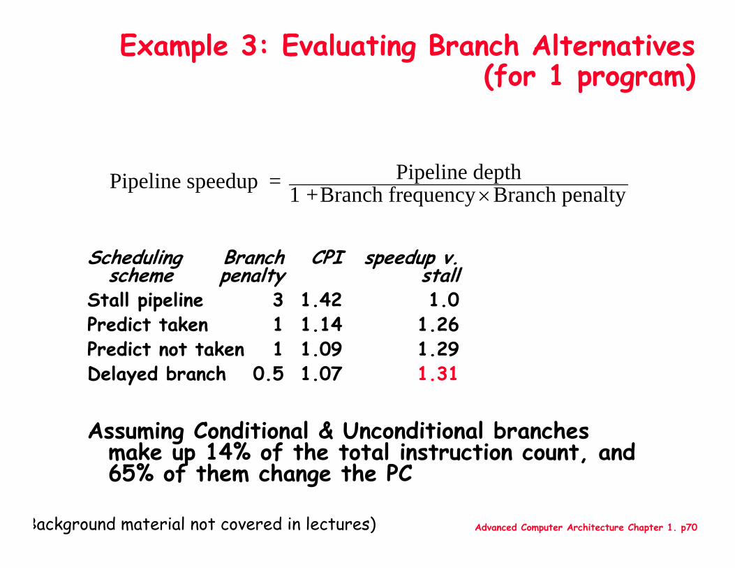
Example 3: Evaluating Branch Alternatives (for 1 program)
Scheduling Branch CPI speedup v.scheme penalty stall
Stall pipeline 3 1.42 1.0Predict taken 1 1.14 1.26Predict not taken 1 1.09 1.29Delayed branch 0.5 1.07 1.31
Assuming Conditional & Unconditional branches make up 14% of the total instruction count, and 65% of them change the PC
Pipeline speedup = Pipeline depth1 +Branch frequency ×Branch penalty
Background material not covered in lectures)

Advanced Computer Architecture Chapter 1. p71
Example 4: Dual-port vs. Single-port
Machine A: Dual ported memory (“Harvard Architecture”)Machine B: Single ported memory, but its pipelined implementation has a 1.05 times faster clock rateIdeal CPI = 1 for bothLoads are 40% of instructions executed
SpeedUpA = Pipeline Depth/(1 + 0) x (clockunpipe/clockpipe)= Pipeline Depth
SpeedUpB = Pipeline Depth/(1 + 0.4 x 1) x (clockunpipe/(clockunpipe / 1.05)= (Pipeline Depth/1.4) x 1.05= 0.75 x Pipeline Depth
SpeedUpA / SpeedUpB = Pipeline Depth/(0.75 x Pipeline Depth) = 1.33
Machine A is 1.33 times faster
(Background material not covered in lectures)