34 21 80 traction power system field acceptance testing 21 80.pdfetp emergency trip panel 9. ets...
TRANSCRIPT

SECTION 34 21 80
TRACTION POWER SYSTEM FIELD ACCEPTANCE TESTING
RELEASE – R3.1.2 SECTION 34 21 80 BART FACILITIES STANDARDS
ISSUED: APRIL 2018 PAGE 1 OF 38 STANDARD SPECIFICATIONS
PART 1 – GENERAL
1.01 OVERVIEW
A. Testing Program
1. The Contractor’s field acceptance testing program shall verify, validate, and document the Traction Power System has been designed, manufactured, constructed, assembled, installed, adjusted, calibrated, and electrically connected to meet the approved design, operational, functional, and performance requirements as specified in the Contract Documents and, approved design and construction submittals.
2. The testing program shall implement a methodical and structured approach that demonstrates all circuits function as intended.
3. The testing program shall comprise of the following testing categories:
a. Installation Verification (IV) tests.
b. Discrete Equipment Field Functional (DEFT) tests.
c. Traction power Facility Functional Tests (FFT).
d. System Integration Tests (SIT).
4. The field acceptance testing specified in this Section and elsewhere in the Contract represents the minimum requirements. Where additional inspection and/or testing requirements are recommended by the respective equipment manufacturers and/or industry standards, include these requirements in the test documentation and processes.
B. Project objectives and design basis shall be in accordance with the following:
1. The project objectives and design basis (inclusive of operational, functional, and performance requirements) shall be verified and validated by the Contractor’s testing program and shall be as embodied in the following documentation:
a. Contract documents.
b. Contractor’s approved design and construction submittals.
c. Requests for information.
d. Change notices.
e. Codes, standards, and local ordinances.
f. Third-Party design and construction requirements.

TRACTION POWER SYSTEM FIELD ACCEPTANCE TESTING
RELEASE – R3.1.2 SECTION 34 21 80 BART FACILITIES STANDARDS
ISSUED: APRIL 2018 PAGE 2 OF 38 STANDARD SPECIFICATIONS
C. Third-party utility services shall be inspected and tested in accordance with the requirements of the respective third-party utility service providers.
D. Definitions of Tests:
1. Installation Verification (IV) tests: Tests conducted following the installation of equipment, cables, and sub-systems, in their prescribed final placement. Tests are intended to demonstrate all equipment, cables, and subsystems are the correct model / configuration and installed and wired to the approved design; free from damage; and are suitable for operation.
2. Discrete Equipment Field Functional (DEFF) tests: A sequence of tests applied to a unit under test to establish whether it is functioning correctly.
3. Traction power Facility Functional Tests (FFT): A sequence of tests shall be applied to a traction power facility under test to establish whether it is functioning correctly.
4. System Integration Tests (SIT) – Testing shall be conducted on a complete, integrated system to evaluate the system’s compliance with its specified requirements.
5. Regression tests (Software) – Selective retesting of a system or component to verify that modifications have not caused unintended effects and that the system or component still complies with the specified requirements.
6. Retest (Equipment and Cables) – Retest of equipment and cables after corrective action undertaken to address a failed condition to verify compliance to the specified requirements.
1.02 SECTION INCLUDES
A. Grounding system tests.
B. Installation verification tests.
C. Separable insulated connector tests.
D. AC isolation disconnect switches tests.
E. AC load break/vacuum fault interrupter and/load break switches tests.
F. AC switchgear tests.
G. 34.5 kV AC busway tests.
H. 1,200V AC and DC bus duct tests.
I. Rectifier transformer tests.
J. Rectifier tests.

TRACTION POWER SYSTEM FIELD ACCEPTANCE TESTING
RELEASE – R3.1.2 SECTION 34 21 80 BART FACILITIES STANDARDS
ISSUED: APRIL 2018 PAGE 3 OF 38 STANDARD SPECIFICATIONS
K. DC switchgear tests.
L. High resistance flooring tests.
M. DC control power system tests.
N. Auxiliary power transformer tests.
O. Negative grounding device tests.
P. Emergency and transfer trip system tests.
Q. Telephone and CCTV equipment tests.
R. Substation functional tests.
S. Short circuit test.
T. Ground fault test.
U. Train start test.
V. Commissioning.
1.03 ABBREVIATIONS AND SYMBOLS
1. AC Alternating Current
2. ATO Automatic Train Operation
3. CFT Contact Fiber Transceiver
4. CPUC California Public Utilities Commission
5. DC Direct Current
6. DEFT Discrete Equipment Field Functional Tests
7. EBP Emergency Backup Panel
8. ETP Emergency Trip Panel
9. ETS Emergency Trip Switch
10. ETTC Emergency Transfer Trip Cabinet
11. ETTS Emergency Transfer Trip System
12. FFT Facility Functional Tests
13. FOT Fiber Optic Transceivers

TRACTION POWER SYSTEM FIELD ACCEPTANCE TESTING
RELEASE – R3.1.2 SECTION 34 21 80 BART FACILITIES STANDARDS
ISSUED: APRIL 2018 PAGE 4 OF 38 STANDARD SPECIFICATIONS
14. GBS Gap Breaker Station
15. HMI Human Machine Interface
16. HVAC Heating, Ventilation and Air Conditioning
17. ICS Integrated Control System
18. ID Identifier
19. I/O Input / Output
20. IOM Input Output Module
21. IPR Integrated Protection Relay
22. IVT Installation Verification Tests
23. kV Kilovolts
24. LV Low Voltage
25. MPR Multi-Function Protection Relay
26. MWS Maintenance Work Station
27. MR Mad Russian
28. NETA InterNational Electrical Testing Association
29. NGD Negative Grounding Device
30. MΩ Mega-ohm
31. OCC Operations Control Center
32. PLC Programmable Logic Controller
33. PTS Platform Trip Switch
34. ROW Right of Way
35. SBBS Sectionalizing Breaker Blocking System
36. SCADA Supervisory Control and Data Acquisition
37. SIT System Integration Tests
38. V Volts
39. VLAN Virtual Local Area Network

TRACTION POWER SYSTEM FIELD ACCEPTANCE TESTING
RELEASE – R3.1.2 SECTION 34 21 80 BART FACILITIES STANDARDS
ISSUED: APRIL 2018 PAGE 5 OF 38 STANDARD SPECIFICATIONS
1.04 RELATED SECTIONS
A. Refer to the following Sections for requirements relating to field acceptance testing activities:
1. Section 01 11 00, Summary of Work
2. Section 01 31 19, Project Meetings
3. Section 01 32 16, Construction Progress Schedules
4. Section 01 33 00 Submittal Procedures
5. Section 01 33 23 Shop Drawings, Product Data, and Samples
6. Section 01 35 14 Operating System Interface
7. Section 01 43 00 Quality Assurance
8. Section 01 45 00 Quality Control
9. Section 01 45 24 Testing Program Requirements
10. Section 01 77 00 Closeout Procedures
11. Section 01 78 39 Project Record Documents
12. Section 20 50 13 Raceways for Facility Services
13. Section 22 14 29 Sump Pumps
14. Section 23 81 00 Unitary HVAC Equipment
15. Section 26 05 17 Dry-Type Transformers
16. Section 26 05 24 Low Voltage Wires and Cables
17. Section 26 24 13 Switchboards
18. Section 26 24 24 Circuit Breakers and Panelboards
19. Section 27 13 01 Communication Cables and Related Equipment
20. Section 27 30 01 Telephone Systems
21. Section 28 10 01 Access Control System
22. Section 28 31 00 Fire Detection and Alarm System
23. Section 28 41 29 Closed Circuit Television System
24. Section 34 21 01 General Requirements for the Traction Power System

TRACTION POWER SYSTEM FIELD ACCEPTANCE TESTING
RELEASE – R3.1.2 SECTION 34 21 80 BART FACILITIES STANDARDS
ISSUED: APRIL 2018 PAGE 6 OF 38 STANDARD SPECIFICATIONS
25. Section 34 21 05 Prefabricated AC and DC Equipment Houses
26. Section 34 21 11 Multi-Function Protection Relay Equipment
27. Section 34 21 12 AC Integrated Protection Relay Equipment
28. Section 34 21 13 Contact Rail System
29. Section 34 21 19 Separable Insulated Connectors
30. Section 34 21 55 Manual DC Disconnect Switch
31. Section 34 21 56 35KV Isolation Disconnect Switch
32. Section 34 21 60 Grounding and Bonding for Traction Power
33. Section 34 22 23 Traction Power Cables
1.05 MEASUREMENT AND PAYMENT
A. Separate measurement and payment will not be made for work required under this Contract Specifications Section. All costs connected with the work specified herein will be included with the related item of work in the Bid Schedule of the Bid Form, or incidental to the Work.
1.06 REFERENCES
A. All inspections and tests shall be in accordance with the latest edition of the following codes, standards, and specifications except as provided otherwise herein. Where requirements conflict with requirements specified herein the more restrictive requirements shall apply.
B. American Society for Testing of Materials (ASTM):
1. ASTM D92 12 Standard Test Method for Flash and Fire Points by Cleveland Open Cup Tester
2. ASTM D445 Standard Test Method for Kinematic Viscosity of Transparent and Opaque Liquids (and Calculation of Dynamic Viscosity)
3. ASTM D877/D877M Standard Test Method for Dielectric Breakdown Voltage of Insulating Liquids Using Disk Electrodes
4. ASTM D923 Standard Practices for Sampling Electrical Insulating Liquids
5. ASTM D924 Standard Test Method for Dissipation Factor (or Power Factor) and Relative Permittivity (Dielectric Constant) of Electrical Insulating Liquids
TRACTION POWER SYSTEM FIELD ACCEPTANCE TESTING
RELEASE – R3.1.2 SECTION 34 21 80 BART FACILITIES STANDARDS
ISSUED: APRIL 2018 PAGE 7 OF 38 STANDARD SPECIFICATIONS
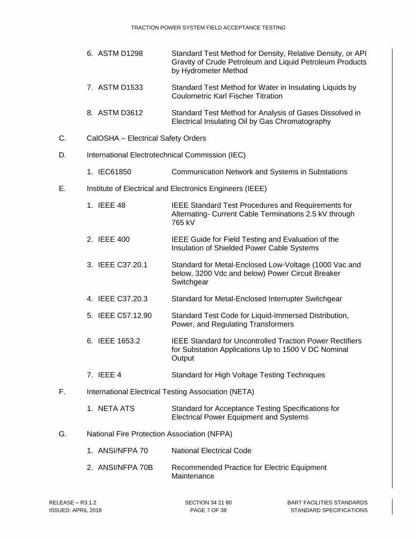
6. ASTM D1298 Standard Test Method for Density, Relative Density, or API Gravity of Crude Petroleum and Liquid Petroleum Products by Hydrometer Method
7. ASTM D1533 Standard Test Method for Water in Insulating Liquids by Coulometric Karl Fischer Titration
8. ASTM D3612 Standard Test Method for Analysis of Gases Dissolved in Electrical Insulating Oil by Gas Chromatography
C. CalOSHA – Electrical Safety Orders
D. International Electrotechnical Commission (IEC)
1. IEC61850 Communication Network and Systems in Substations
E. Institute of Electrical and Electronics Engineers (IEEE)
1. IEEE 48 IEEE Standard Test Procedures and Requirements for Alternating- Current Cable Terminations 2.5 kV through 765 kV
2. IEEE 400 IEEE Guide for Field Testing and Evaluation of the Insulation of Shielded Power Cable Systems
3. IEEE C37.20.1 Standard for Metal-Enclosed Low-Voltage (1000 Vac and below, 3200 Vdc and below) Power Circuit Breaker Switchgear
4. IEEE C37.20.3 Standard for Metal-Enclosed Interrupter Switchgear
5. IEEE C57.12.90 Standard Test Code for Liquid-Immersed Distribution, Power, and Regulating Transformers
6. IEEE 1653.2 IEEE Standard for Uncontrolled Traction Power Rectifiers for Substation Applications Up to 1500 V DC Nominal Output
7. IEEE 4 Standard for High Voltage Testing Techniques
F. International Electrical Testing Association (NETA)
1. NETA ATS Standard for Acceptance Testing Specifications for Electrical Power Equipment and Systems
G. National Fire Protection Association (NFPA)
1. ANSI/NFPA 70 National Electrical Code
2. ANSI/NFPA 70B Recommended Practice for Electric Equipment Maintenance

TRACTION POWER SYSTEM FIELD ACCEPTANCE TESTING
RELEASE – R3.1.2 SECTION 34 21 80 BART FACILITIES STANDARDS
ISSUED: APRIL 2018 PAGE 8 OF 38 STANDARD SPECIFICATIONS
3. ANSI/NFPA 70E Standard for Electrical Safety in the Workplace
4. ANSI/NFPA 101 Life Safety Code
5. ANSI/NFPA 110 Emergency and Standby Power Systems
6. ANSI/NFPA 130 Standard for Fixed Guideway Transit and Passenger Rail
7. ANSI/NFPA 780 Installation of Lightning Protection Systems
H. State and local codes and ordinances
I. Underwriters Laboratories, Inc. (UL)
1.07 TESTING RESPONSIBILITIES
A. Refer to Section 01 45 24 for:
1. Testing responsibilities
2. Requirements for testing organizations and test personnel
3. Test documentation
4. Test schedules
5. Traction power system studies
6. Rejection and retesting and regression testing
7. Test equipment calibration
8. Safety requirements
1.08 SUBMITTALS
A. Refer to the following Sections for additional requirements:
1. Section 01 33 00 Submittal Procedures.
2. Section 01 33 23 Shop Drawings, Product Data and Samples.
B. Submit the following documents for all equipment, cables and software provided under the Contract for the Traction Power System:
1. Qualifications and resumes of testing personnel: – NTP plus 30 days.
2. Test program plan: NTP plus 45 days.
3. Schedule (Overall): NTP plus 45 days with updates provided per Section 01 32 16, Construction Progress Schedules.

TRACTION POWER SYSTEM FIELD ACCEPTANCE TESTING
RELEASE – R3.1.2 SECTION 34 21 80 BART FACILITIES STANDARDS
ISSUED: APRIL 2018 PAGE 9 OF 38 STANDARD SPECIFICATIONS
4. Schedule (four (4) week look ahead): Weekly (part of progress report to Engineer).
5. Checklists: 90 days before the start of the respective test.
6. Independent transformer oil and battery testing organizations: 90 days before start of the respective test.
7. Independent surveyor qualifications: 90 days before surveys are conducted.
8. Test procedures: 90 days before the start of the respective test.
9. General test data sheets: 45 days before the start of the respective test.
10. Site specific test data sheets: 30 days before the start of the respective test.
11. Test records shall be submitted in accordance with the following:
a. Unofficial test results within twenty fours (24) hours of completing the test.
b. Official test results within 10 days of completing the test.
12. Issues Tracking Logs: Weekly (as part of progress report submitted to the Engineer).
13. Energization plan: 90 days before energization of the traction power system
14. Test documentation metrics – Weekly (as part of progress report to the Engineer).
15. Project Closeout Test Documents.
16. Incident Reports – Within 12 hours.
C. Prior to commencement of a test, the records for pre-requisite inspections and test(s) shall be submitted to and approved by the District and any outstanding discrepancies shall be completed.
D. Prior to substantial completion, the following shall apply:
1. All testing, retesting and regression testing activities have been completed.
2. All FAT and field inspection punch list and testing discrepancies have been corrected, closed out and disposition with the District approval.
3. Configuration control documentation is up to date for the completely tested as-built traction power facilities.
4. All test records have been submitted and approved by the District.
5. Safety certification documentation is complete, submitted to and approved by the District.

TRACTION POWER SYSTEM FIELD ACCEPTANCE TESTING
RELEASE – R3.1.2 SECTION 34 21 80 BART FACILITIES STANDARDS
ISSUED: APRIL 2018 PAGE 10 OF 38 STANDARD SPECIFICATIONS
6. Independent transformer oil testing laboratory and battery testing organization certifications, submitted to and approved by the District.
7. Independent surveyor qualifications, submitted to and approved by the District.
8. Follow test plans, procedures, and test reports for all tests specified in associated contract specifications section noted herein in Article 1.02, related contract specifications sections.
9. Include test plans and procedures for Installation Verification tests and for tests of all ac and dc equipment houses, rectifier transformers, and other ancillary equipment, either provided by the Contractor or by Others as part of the facility being tested.
E. Submit test reports for all equipment provided at each work location for:
1. Portable TPSS AC Vacuum Fault Interrupter (VFI), in accordance with Section 34 21 07, Prefabricated Portable Substations.
2. 35 kV AC Cable, in accordance with Section 34 22 23, Traction Power Cables.
3. DC Cable, in accordance with Section 34 21 23, Traction Power Cables.
4. AC Switchgear, in accordance with AC Switchgear Tests, in this section.
5. 1200A Bus Duct and DC Cable, in accordance with 1200A Bus Duct and DC Cable Tests, in this section.
6. Rectifier Transformers, in accordance with Rectifier Transformer Tests, in this section.
7. Rectifiers, in accordance with Rectifier Tests, in this section.
8. DC Switchgear, in accordance with DC Switchgear Tests in this section.
9. High Resistance Flooring, in accordance with House High Resistance Flooring Tests, in this section.
10. Auxiliary Power Transformers, in accordance with Auxiliary Power Transformer Tests, in this section.
11. Separable Insulated Connector in accordance with Separable Insulated Connector, in this section.
12. AC Isolation Disconnect Switches in accordance with AC Isolation Disconnect Switches, in this section.
13. 125V DC Control Power System, in accordance with DC Control Power System Tests, in this section.
14. Negative Grounding Devices, in accordance with Negative Grounding Device Tests, in this section.

TRACTION POWER SYSTEM FIELD ACCEPTANCE TESTING
RELEASE – R3.1.2 SECTION 34 21 80 BART FACILITIES STANDARDS
ISSUED: APRIL 2018 PAGE 11 OF 38 STANDARD SPECIFICATIONS
15. CO2 Panel in accordance with Article Panel Tests in this section.
16. Emergency Transfer Trip System, in accordance with Emergency Transfer Trip System (ETTS) Tests, in this section.
17. CCTV Equipment, in accordance with Section 28 41 29, CCTV Equipment.
18. Telephone Equipment, in accordance with Section 27 30 01, Telephone Equipment.
19. Access control equipment, in accordance with Section 28 10 01, Access Control System.
F. Submit TPSS Functional Test reports in accordance with Substation Functional Tests, in this section.
1.09 GUARANTY/WARRANTY
A. Tests shall not alter the Contractor's guaranty and warranty of the Traction Power System. Replace and retest work and materials found to be in noncompliance with the Contract Documents at no additional cost to the District.
PART 2 – PRODUCTS
A. Not Used
PART 3 – EXECUTION
3.01 GENERAL
A. All tests shall be carried out in accordance with detailed and pre-approved testing program plans, procedures and data sheets.
B. Testing specified in this Section shall only be performed following completion of equipment and cable installation and associated punch list items.
3.02 TEST INSTRUMENTS AND TOOLS
A. Contractor shall furnish, the following test tools and instruments for use in field testing:
1. Fiber optic cable test equipment.
2. Ground grid fall of potential type test equipment.
3. Torque wrenches.

TRACTION POWER SYSTEM FIELD ACCEPTANCE TESTING
RELEASE – R3.1.2 SECTION 34 21 80 BART FACILITIES STANDARDS
ISSUED: APRIL 2018 PAGE 12 OF 38 STANDARD SPECIFICATIONS
4. Di-electric withstand (hi-potential) tester capable of generating voltages up to 80 kV.
5. Insulation resistance (megger) tester capable of performing tests up to 5 kV.
6. Low resistance ohm-meter.
7. 1,500V dc power supply.
8. 480V ac power supply.
9. Voltage and current signal generators.
10. Meters as necessary to measure specified testing and commissioning electrical data.
11. Noise meters.
12. Thermal imaging equipment.
B. All test tools and instruments shall be certified in accordance with Contract Specifications Section 01 45 24, Testing Program Requirements.
C. Additional tests involving operation of the traction power facilities with other BART operating systems including BARTNet, SCADA, telephone system, and other end-to-end tests covered under Systems Integration Testing is specified elsewhere.
D. MV cable (35 kV, 2.4 kV, 1000 V), LV cable (LV power, Controls and Indications) and fiber optic cable test requirements are specified in Section 34 22 23, Traction Power Cables, Section 26 05 24, Low Voltage Wires and Cables, and Section 27 13 01, Communication Cables and Related Equipment, respectively.
E. LV power equipment test requirements are specified in the following Sections:
1. Section 26 05 17 Dry-Type Transformers
2. Section 26 24 13 Switchboards
3. Section 26 24 24 Circuit Breakers and Panelboards
F. Ground grid test requirements are specified in Section 34 21 60, Grounding and Bonding for Traction Power Substations.
G. Testing activities shall be coordinated and scheduled with the Engineer, and account for constraints imposed by any of the following:
1. Scheduled revenue services and special events.
2. Availability of District resources and personnel.
3. Track and/or traction power facility access.

TRACTION POWER SYSTEM FIELD ACCEPTANCE TESTING
RELEASE – R3.1.2 SECTION 34 21 80 BART FACILITIES STANDARDS
ISSUED: APRIL 2018 PAGE 13 OF 38 STANDARD SPECIFICATIONS
4. The District’s standard operating procedures.
5. Schedule maintenance and renewal activities by District personnel.
6. Scheduled activities of other contractors working on and adjacent to the area of the Work.
H. Where the test execution and associated test records deviates from the approved test procedures, the Contractor and its sub-contractors shall demonstrate equivalency and conduct all the tasks within the approved test procedures at no additional cost to the District.
I. Installation punch list and testing discrepancies shall be categorized under the following categories:
1. Safety Related
2. Code Violations
3. Contract and/or Design Non-Compliances
4. Critical Operational Requirements
5. Non-Safety Related
3.03 INSTALLATION VERIFICATION TESTS
A. Equipment Assembly Inspection shall be performed by verifying the following:
1. All equipment shipping bracing has been removed.
2. Enclosures and equipment are anchored correctly and are level, with all seismic anchors and supports correctly installed.
3. Assembled on-site houses and equipment, including components and accessories, are correctly installed and labeled in accordance with approved shop drawings, and are in operable condition.
4. Physical damage, cracked insulators, and tightness of connections, defective wiring, and general mechanical and electrical conditions are noted.
5. Record all part numbers and serial numbers, and equipment nameplate data and main coil identification numbers.
B. Verify presence of voltage shock hazard and arc-flash hazard warning safety labels (per NFPA 70E) and all other safety, warning labels, and signage required by the equipment manufacturer and CalOSHA are visibly installed on the front side, and at other access points, of the equipment enclosures.

TRACTION POWER SYSTEM FIELD ACCEPTANCE TESTING
RELEASE – R3.1.2 SECTION 34 21 80 BART FACILITIES STANDARDS
ISSUED: APRIL 2018 PAGE 14 OF 38 STANDARD SPECIFICATIONS
C. Grounding connections inspection shall be performed by verifying the following
1. Verify that all enclosure, equipment, and relay grounding connections inside and outside of the ac and dc equipment houses, and rectifier transformer ground connections are in place, and properly made.
2. Verify using approved drawings, which shall be marked as to completion.
D. Each portable TPSS and permanent TPSS rectifier transformer oil containment vessel or structure is watertight shall be verified by performing the following:
1. Fill containment vessel with water to a depth of two (2) inches for one (1) 24-hour period.
2. If test is done in rainy weather with damp ground structure around containment vessel, use a small amount of dye in the test water to verify that test water does not leak outside of the containment.
3. Following test, verify that opening of containment drain valve results in draining all test liquid from the containment structure or vessel.
E. Verify all control power connections, including alarms, trips, lights, heaters, and control power operations meet specified requirements. 34.5 kV incoming primary power connections and secondary bus connections shall not be made during Installation Verification Tests. Verify using approved drawings, which shall be marked as to completion.
F. Verify 480V ac auxiliary transformer wiring, neutral and tap jumpers are installed correctly and identified.
G. Verify that each battery system interconnection is torqued to manufacturer’s recommended torque value.
H. Verify all doors for correct gaskets, closing and latching, and padlock provisions. Temporary locks shall be provided for securing the enclosures.
I. Mechanical Integrity Tests:
1. Perform mechanical checks on the physical integrity of all equipment. These tests shall include, verifying the correct alignment of the racking mechanism of all circuit breakers by withdrawing and inserting the breaker module, verifying interlocks, contact gap spacing, correct bus connection torqueing and placing of torque marks, confirming correct switch blade alignment, good blade contact pressure when closed, adequate blade separation when open, and checking all doors and access panels.
2. Perform mechanical checks on the physical integrity of all 34.5 kV ac switchgear equipment. These tests shall be performed to demonstrate proper operation of the interlocking system between the vacuum circuit breakers and the associated three position disconnector and grounding switches.

TRACTION POWER SYSTEM FIELD ACCEPTANCE TESTING
RELEASE – R3.1.2 SECTION 34 21 80 BART FACILITIES STANDARDS
ISSUED: APRIL 2018 PAGE 15 OF 38 STANDARD SPECIFICATIONS
3. Interchangeability of like-rated dc feeder breakers shall be confirmed. A dc feeder breaker shall not be interchangeable with a switchgear cubicle designed for a circuit breaker with a different rating. Dc feeder circuit breakers shall not be interchangeable with dc cathode circuit breakers.
4. Verify correct mechanical and key interlocking. Transfer extra Kirk Keys to a secure location as directed by the District.
J. Tighten electrical connectors and terminals per manufacturer's published torque-tightening values. If manufacturer's torque values are not available, use those specified in UL 486A and UL 486B. The Engineer will check torque values of at least 10 percent of each type of bolted connection. If any torque value fails to meet torque criteria, then all bolted connections of that type shall be checked for correctness.
K. Settings and Calibration: Verify the proper settings of all relays, and other protective and control systems and devices. Settings, including software parameters and configuration, shall be per approved coordination study. Confirm correct ratings of medium voltage fuses.
L. Confirm by injection of signals that all equipment, potential transformers, and current transformer polarities are correct, for:
1. Vacuum fault interrupter
2. Rectifier transformers
3. 34.5 kV ac switchgear
M. Confirm by bench testing or by injection of signals into installed equipment that all protective relays function in accordance with manufacturer’s published data.
N. DC control power system checks shall verify and ensure the following:
1. Each inter cell connection is tight
2. All battery post seals are intact
3. All shipping caps are replaced with vent caps
O. Verify space heater operation
P. Verify correct voltages at all receptacles
Q. Weatherproofing tests: Following installation of each substation enclosure, complete with throat connection assemblies and dc cable bus enclosures shall be tested in accordance with IEEE C37.20.1. Contactor shall also test each AC bus duct and associated connections to the rectifier transformer and DC equipment house to the same standard.
R. Inter-cabinet field installed wiring: Verify each wire is correctly terminated and continuity based on Contractor prepared interconnection diagrams.

TRACTION POWER SYSTEM FIELD ACCEPTANCE TESTING
RELEASE – R3.1.2 SECTION 34 21 80 BART FACILITIES STANDARDS
ISSUED: APRIL 2018 PAGE 16 OF 38 STANDARD SPECIFICATIONS
S. Confirm correct AC switchgear SF6 gas pressure. If SF6 pressure is lower than manufacturer’s recommended value, then add gas to bring pressure to the recommended value.
T. All equipment shall be inspected in accordance with Article 3.03, Equipment Assembly Inspection.
3.04 DISCRETE EQUIPMENT FIELD FUNCTIONAL TESTS
A. General
1. Field engineering and quality control associated with field testing activities shall be performed in accordance with the requirements specified in the following Sections:
a. Section 01 43 00 Quality Assurance
b. Section 01 45 00 Quality Control
c. Section 01 71 23 Field Engineering
2. Furnish equipment for testing power, lighting and control circuits after installation, including service test kit.
3. Correct malfunctioning units on-site, where possible, and retest to demonstrate compliance; otherwise, replace with new units and retest at no additional cost to the District.
4. For all tests provide test instrument certification data and pass/fail criteria, and record date, time, temperature, humidity, voltage levels, and leakage current, meg-ohms, or resistance values, as applicable.
B. AC isolation disconnect switches tests
1. Equipment shall be completely assembled, equipped with devices, installed and field tested in accordance with NETA ATS requirements.
C. AC Vacuum Fault Interrupter Tests
1. Equipment shall be completely assembled, equipped with devices, installed, and field tested in accordance with NETA ATS requirements.
D. AC Switchgear Tests
1. General
a. Tests shall be performed on all 34.5 kV ac circuit breakers and ac switchgear bus assemblies and three position disconnector switches.
b. Tests shall be performed prior to connecting 35 kV cables and switchgear instrument transformers, and with AC bus duct disconnected from ac

TRACTION POWER SYSTEM FIELD ACCEPTANCE TESTING
RELEASE – R3.1.2 SECTION 34 21 80 BART FACILITIES STANDARDS
ISSUED: APRIL 2018 PAGE 17 OF 38 STANDARD SPECIFICATIONS
switchgear bus or from the line side of the disconnector switches and load side of the circuit breakers.
c. Tests shall be performed with potential transformer leads disconnected from the ac switchgear bus.
2. Circuit Continuity Tests – Perform continuity checks to verify current transformer connections, shunt leads, and all medium voltage fuses.
3. Resistance tests shall be performed in accordance with the following:
a. Using a low-resistance ohmmeter, check resistance of all bolted bus connections, including instrument transformer connections, and of closed circuit breaker contacts of each phase of each circuit breaker.
b. For each AC switchgear line-up tested, if the resistance of any phase differs by more than 50 percent from the lowest value among phases at that line-up, take remedial measures to bring high value to within 50 percent of the lowest value, and retest.
4. Insulation resistance tests shall be performed in accordance with the following:
a. Perform insulation resistance (megger) tests at 5,000 volts for one minute at each circuit breaker pole, phase-to-phase, and phase-to-ground with each circuit breaker closed, and across each open pole.
b. Perform insulation resistance tests at 5,000 volts for one minute at each current transformer connection, coil-to-ground.
c. Perform insulation resistance tests at 5,000 volts for one minute at each potential transformer pole, primary-to-ground with secondary winding grounded.
d. Measured insulation resistance shall be 20,000 M, minimum.
e. Repeat insulation resistance tests following completion of dielectric withstand tests.
5. Dielectric withstand tests shall be performed in accordance with the following:
a. With the switching device contacts closed, perform dielectric withstand (high potential) tests at 60 kV for five minutes between each phase with the circuit breaker or between each phase of the combined disconnector switch and circuit breaker with the frame and other phases grounded.
b. With the switching device contacts open, perform dielectric withstand (high potential) tests at 60 kV for five minutes between each phase with the circuit breaker or between each phase of the combined disconnector switch and circuit breaker with the frame and other phases grounded.
c. Measured leakage current across open contacts of each phase shall be less
than 10 A, maximum or manufacturers recommended value, whichever is less.
E. 1200V AC bus duct tests shall be performed in accordance with the following:

TRACTION POWER SYSTEM FIELD ACCEPTANCE TESTING
RELEASE – R3.1.2 SECTION 34 21 80 BART FACILITIES STANDARDS
ISSUED: APRIL 2018 PAGE 18 OF 38 STANDARD SPECIFICATIONS
1. General
a. Tests shall be performed on all 1,200V bus duct assemblies connecting traction power transformers and rectifiers.
b. Tests shall be performed with bus duct sections assembled, and bus duct disconnected from transformer and rectifier, and dc power cable connections disconnected from the rectifiers and dc switchgear.
c. Prior to testing, inspect and confirm that all bolted connections are torqued to values specified, and torque marks indicating correct torque are clearly marked. Record torque value for each connection in test report.
2. Resistance tests shall be performed in accordance with the following:
a. Using a low-resistance ohmmeter, check resistance of each bolted bus connection of each phase.
b. For each bus duct or cable connection tested, if the resistance of any phase differs by more than 50 percent from the lowest value among phases at that bus duct or cable connection, take remedial measures to bring high value to within 50 percent of the lowest value, and retested.
3. Insulation resistance tests shall be performed in accordance with the following:
a. Perform insulation resistance (megger) tests at 2,500 volts for one minute for each phase, phase-to-phase and phase-to-ground (per NETA 7.1.1).
b. Measured insulation resistance shall be 1,000 M, minimum (per NETA 7.1.1).
c. Repeat insulation resistance test following completion of dielectric testing.
F. Rectifier Transformer Tests
1. General
a. Tests shall be performed on all rectifier transformers, per IEEE C57.12.90.
b. Tests shall be performed prior to connecting line side 35 kV connectors and cables and load side 784V system cables.
c. Prior to energizing transformer, note oil pressure, temperature, and hot-spot indicator readings for comparison with readings following energization.
2. Turns Ratio Tests – Perform turns ratio tests at all tap positions, per IEEE C57.12.90.
3. Insulation resistance tests shall be performed in accordance with the following:
a. Perform insulation resistance (megger) tests at 5,000 volts for one minute from primary transformer windings to each group of secondary transformer windings. Conduct tests with secondary windings grounded. Note that the traction power transformers have three (3) sets of windings: primary delta, secondary delta, and secondary wye.

TRACTION POWER SYSTEM FIELD ACCEPTANCE TESTING
RELEASE – R3.1.2 SECTION 34 21 80 BART FACILITIES STANDARDS
ISSUED: APRIL 2018 PAGE 19 OF 38 STANDARD SPECIFICATIONS
b. Measured insulation resistance on the primary side shall be 1,000 M minimum.
c. Perform insulation resistance (megger) tests at 2,500 volts for one minute from each group of secondary transformer windings to primary side transformer windings. Conduct tests on each group of secondary windings with the other secondary winding group grounded and the primary windings grounded.
d. Measured insulation resistance on the secondary side shall be 1,000 M, minimum.
e. Repeat insulation resistance tests following completion of dielectric testing.
4. Dielectric withstand tests shall be performed in accordance with the following:
a. Perform dielectric withstand (high potential) tests at 60 kV AC for five minutes on each primary winding with the secondary windings grounded.
b. Perform dielectric withstand tests at 8.5 kV AC for five minutes on each secondary winding with the windings not under test grounded.
5. Insulating Oil Tests shall be performed in accordance with the following:
a. For each rectifier transformer, remove a sample of insulating liquid in accordance with ASTM D923, and test for the following:
1) Dielectric breakdown voltage: ASTM D877.
2) Dissolved-gas analysis: ASTM D3612.
3) Flash Point ASTM D924.
4) Fire Point ASTM D92.
5) Specific Gravity ASTM D1298.
6) Fire point test.
7) Check oxygen content and total combustible gas content of nitrogen gas cushion in sealed tank transformers. A total combustible gas test, where applicable, and a dissolved gas-in-oil test of the dielectric fluid should also be made soon after the transformer is in service at operating temperature to provide a suitable post-energization reference “bench mark”.
b. If oil does not completely fill containment tank, inject inert gas as required by manufacturer’s instructions.
G. Rectifier Tests
1. General
a. Tests shall be performed on all rectifiers per IEEE 1653.2.
b. Tests shall be performed prior to connecting line side ac system cables and 1000V main dc switchgear bus.

TRACTION POWER SYSTEM FIELD ACCEPTANCE TESTING
RELEASE – R3.1.2 SECTION 34 21 80 BART FACILITIES STANDARDS
ISSUED: APRIL 2018 PAGE 20 OF 38 STANDARD SPECIFICATIONS
c. Tests shall be performed with diode bridges shorted and 164 Device Relay and 180 Device Diode Monitoring Circuits disconnected from the rectifier.
2. Resistance tests shall be performed in accordance with the following:
a. Using a low-resistance ohmmeter, check resistance of each bolted connection of each rectifier phase to main dc bus.
b. For each rectifier tested, if the resistance of any phase differs by more than 50 percent from the lowest value among diode bridge connections, take remedial measures to bring high value to within 50 percent of the lowest value, and retest.
3. High resistance grounding isolation tests shall be performed in accordance with the following:
a. Prior to test, rectifier mounting connections for cracks or other deficiencies that would compromise high resistance grounding isolation.
b. Perform Isolation (megger) test at 2,500 volts for one minute between rectifier frame and ground to verify isolation from ground. DC switchgear shall be electrically disconnected from the rectifier at the dc switchgear isolation cabinet.
c. Measured isolation resistance shall be 1,000 M, minimum.
d. Repeat isolation tests following completion of dielectric testing.
4. Dielectric Withstand Tests
a. During dielectric withstand tests, all diodes and diode stacks shall be jumpered together to maintain all diode stacks at the same potential.
b. Perform dielectric withstand tests at 5 kV DC for one minute on rectifier diode assembly, as one complete unit.
c. Ground low voltage indication circuits for test.
H. DC Switchgear Tests
1. General
a. Tests shall be performed on all 1000V DC circuit breakers and dc switchgear bus assemblies.
b. Tests shall be performed prior to connecting 1000V DC system cables, and with rectifier bus disconnected from dc switchgear bus.
c. Test shall be performed with 164 Device Relays disconnected from the dc switchgear.
2. Circuit Continuity Tests – Perform continuity checks to verify shunt leads, and all 1000V dc system fuses
3. Resistance Tests

TRACTION POWER SYSTEM FIELD ACCEPTANCE TESTING
RELEASE – R3.1.2 SECTION 34 21 80 BART FACILITIES STANDARDS
ISSUED: APRIL 2018 PAGE 21 OF 38 STANDARD SPECIFICATIONS
a. Using a low-resistance ohmmeter, check resistance of all bolted bus connections and of closed circuit breaker contacts of each circuit breaker.
b. For each DC switchgear line-up tested, if the resistance of any connection differs by more than 50 percent from the lowest value among similar connections, take remedial measures to bring high value to within 50 percent of the lowest value, and retest.
4. Insulation resistance tests shall be performed in accordance with the following:
a. Perform insulation resistance (megger) tests at 2.5 kV for one minute at each circuit breaker pole with circuit breaker closed, and across open pole.
b. Measured insulation resistance shall be 1,000 M, minimum.
c. Repeat insulation resistance tests following completion of dielectric testing.
5. High resistance grounding isolation tests shall be performed in accordance with the following:
a. Prior to conducting high resistance grounding isolation test, inspect dc switchgear mounting connections for cracks or other deficiencies that would compromise high resistance grounding isolation.
b. Isolation tests shall be conducted with all circuit breakers inserted in their switchgear cubicles and closed.
c. Perform isolation (megger) test at 5 kV DC for one minute between each switchgear cubicle frame and ground, and from each switchgear cubicle frame to the adjacent cubicle or rectifier frames, to verify isolation from ground.
d. Isolate one cubicle frame from the switchgear lineup and ground the rest of the switchgear lineup frame. Perform isolation test at 5 kV DC kV for one minute between isolated cubicle frame and ground. Repeat test for each cubicle frame.
e. Perform isolation test at 5 kV DC for one minute between dc switchgear negative bus and ground.
f. Measured isolation resistance for all tests shall be 1,000 M, minimum.
I. High Resistance Flooring Tests
1. General
a. Perform tests on high resistance flooring installed in all District Furnished DC equipment houses.
b. Tests shall be done with following pre-requisites:
1) Insulated equipment not being tested to be grounded
2) DC house base properly grounded, with ground integrity previously verified by test

TRACTION POWER SYSTEM FIELD ACCEPTANCE TESTING
RELEASE – R3.1.2 SECTION 34 21 80 BART FACILITIES STANDARDS
ISSUED: APRIL 2018 PAGE 22 OF 38 STANDARD SPECIFICATIONS
2. High resistance floor isolation tests shall be performed in accordance with the following:
a. Test high resistance floors at 5 kV dc for 1 minute using a 6-inch square (minimum) weighted test plate with meter connected between the test plate and the DC house structure ground. Apply a high conductivity saline solution, 2/3 water, 1/3 salt, between test plate and floor surface to ensure good electrical contact. Test locations shall be 24 inches apart covering the entire floor surface. Perimeter locations shall be within six inches of the edge. Minimum isolation resistance shall be 1,000 megohms, minimum.
b. Measured isolation resistance for all tests shall be 1,000 M, minimum.
J. Liquid immersed type auxiliary power transformer tests shall be performed in accordance with the following:
1. Perform insulation-resistance tests per NETA recommendations (temperature corrected), winding-to-winding and windings-to-ground, utilizing a megohmmeter with test voltage output per manufacturer’s recommendation. Test duration shall be 10 minutes with resistances tabulated at 30 seconds, 1 minute, and 10 minutes. Dielectric absorption ratio and polarization index shall be calculated.
2. Test insulation resistance for each bus, component, connecting supply, feeder, and control circuit.
3. Perform tests and adjustments for control and alarm functions.
4. Perform winding resistance test and ensure deviation is less than 0.5 percent from either the adjacent coils or the calculated ratio.
5. Verify that the tap changer is set at specified ratio.
6. Test continuity of each circuit.
K. 125V DC control power system tests shall be performed in accordance with the following:
1. Battery System Tests
a. Verify all battery charger functions and alarms.
b. Perform resistance measurements using battery internal resistance tester Verify that cell internal resistance values do not vary by more than 25 percent between identical cells that are in a fully charged state.
c. Measure battery charger float and equalize voltages. Verify that values are in accordance with manufacturer’s published data.
d. Measure temperature of every sixth cell to determine average battery temperature. The test time or required current discharge shall be adjusted for the temperature of the battery.

TRACTION POWER SYSTEM FIELD ACCEPTANCE TESTING
RELEASE – R3.1.2 SECTION 34 21 80 BART FACILITIES STANDARDS
ISSUED: APRIL 2018 PAGE 23 OF 38 STANDARD SPECIFICATIONS
e. It shall be verified that all 34.5 kV ac and 1 kV dc circuit breakers are closed, then disconnect battery charger from batteries. Battery discharge shall supply following loads over 8 hours:
1) Normal continuous demand of station ancillary loads.
2) Open, close, and open again all 34.5 kV ac and 1 kV dc breakers after 8 hours.
f. Measure each cell voltage and the battery terminal voltage at the beginning of the test, at least once during the test, and near the end of the test. Verify measured values are in accordance with manufacturer’s published data.
L. Negative Grounding Device Tests shall be performed in accordance with the following:
1. General
a. Perform tests on Negative Grounding Device.
b. Prior to testing, verify that NGD parameters.
2. Negative bypass switch tests shall be performed in accordance with the following:
a. Demonstrate that switch opens and closes properly, and that C02 bypass switch indication LED correctly indicates.
b. Verify that switch operates in the absence of 125V dc control power.
c. Using voltage signal generator, show that switch blocking functions correctly:
1) A voltage of ≥ 20V dc between dc negative bus and ground bus shall
inhibit switch closing.
2) A current of ≥ 20A through switch shall inhibit switch opening
3. Demonstrate that NGD operates in the absence of 125V dc control power.
4. Functional Tests: Using voltage signal generator, demonstrate proper function for following conditions:
a. Positive high current
b. Negative high current
c. Positive timed current
d. Negative timed current
M. Manual DC Disconnect Switch Tests shall be performed in accordance with the following:
1. Perform dielectric (HiPot) tests on the equipment after installation in the field, in accordance with the manufacturer's recommended field testing.
a. Apply minimum 3kV AC phase to phase and each phase to ground for 1 minute. No breakdown or failure shall occur.

TRACTION POWER SYSTEM FIELD ACCEPTANCE TESTING
RELEASE – R3.1.2 SECTION 34 21 80 BART FACILITIES STANDARDS
ISSUED: APRIL 2018 PAGE 24 OF 38 STANDARD SPECIFICATIONS
2. Test contact resistance to confirm manufacturer’s recommended value is met.
3. Perform functional and operational tests to verify that equipment functions in accordance with requirements specified herein, including proper status indication at the associated traction power facility and the Operations Control Center (OCC).
N. C02 panel tests shall be performed in accordance with the following:
1. Test and verify the correct operation of all hard-wired and communication-based interfaces of the C02 panel with traction power equipment at the traction power facility, which is controlled and monitored by the C02 panel.
2. Verify correct function of monitoring and control functions for transformers, negative grounding device, disconnect switches, and traction power equipment in each AC and DC equipment houses at each traction power facility. Confirm data transfer performance between the CO2 PLC, operator and mimic panels, and field equipment. Test by operating equipment to generate contact closures at the IOMs, MPRs, IPRs and NGD. Current injection or application of test voltages to millivolt shunts may be used to confirm correct operation of protective devices.
3. Verify discrete inputs by observing the status change on the mimic panel and/or the C02 display panel as applicable. Discrete outputs to equipment shall be verified by observing equipment status change on the individual breaker display panels, the C02 mimic panel and C02 display panel as applicable.
4. Demonstrate correct performance of all C02 operator panel display functions, including current alarms screen, alarms history screen, current equipment status, and traction power facility and vicinity single line diagram (default screen).
5. Verify that hard-wired alarms for all equipment including the protective relays, CFCs and FOTs in the ETTC, AC and DC control power circuits, 125 V DC battery and charger system, HVAC equipment, fire alarm systems, intrusion detection systems, communication sub-systems, and access control system operate correctly and display correctly on the C02 panel display.
6. Verify correct function of real-time analog data generation (inputs from instrument transformers, transducers, IPRs, and MPRs. Confirm correct transmission over the Ethernet and the display on the C02 panel. Check and verify device calibration and analog outputs from the C02 PLC to the meters mounted on the C02 mimic panel. Confirm all data updates take less than or equal to 1 second between application of signal at field device and display on C02 panel meter.
O. Sectionalizing breaker blocking system (SBBS) tests shall be performed in accordance with the following:
1. Verify the proper operation of the communication links between the blocking master controller and blocking auxiliary controller, located in traction power facilities.

TRACTION POWER SYSTEM FIELD ACCEPTANCE TESTING
RELEASE – R3.1.2 SECTION 34 21 80 BART FACILITIES STANDARDS
ISSUED: APRIL 2018 PAGE 25 OF 38 STANDARD SPECIFICATIONS
2. Confirm that correct data required by the blocking logic is received by the master controller from the auxiliary controller, and that permissive or blocking signals are correctly transmitted from the master controller to the auxiliary controller.
3. Verify the proper operation of the communication links between the master controller and similar master controllers used in the blocking system on the existing System.
4. Verify that correct data is received for the status of the traction power facilities on the existing System as required for the operation of the blocking logic provided under the Contract. Conversely verify the master controller(s) provided under the Contract is/are transmitting correct data for the status of the traction power facilities to existing traction power facilities on the existing System, as required for the operation of a similar blocking scheme on the System.
5. Conduct test to confirm the proper operation of the blocking on closing logic for all 34.5 kV sectionalizing circuit breakers.
6. Confirm the proper operation of all alarm functions and status indications of the 34.5 kV blocking scheme, their recording in the C02 PLC of the same traction power facility, and transmittal to the ICS & EBP workstations.
P. VLAN and IP Address Verification
1. Confirm correct VLAN and IP Address configurations of all Ethernet enabled equipment.
2. Confirm ability to connect remotely and communicate with all Ethernet enabled equipment.
Q. Miscellaneous tests shall be performed in accordance with the following:
1. Third party Utility Services to Traction Power Facility Sites - Verify the required services have been inspected and tested in accordance with the requirements specified herein and/or elsewhere in the Contract.
2. DC Power Supply System Tests: Perform tests on the 125 and 24 VDC systems in accordance with Section 34 21 40, DC Control Power System.
3. Validate 480V AC automatic transfer switch operation, check functions of all L0X and D0X panels, check L0X and D0X undervoltage indications.
4. LV Lighting and Receptacles Tests – Verify the operability of all lighting and receptacle circuits. Verify the lighting levels at ground level meets the specified requirements.
5. HVAC System Tests: Perform tests in accordance with Section 23 81 00, Unitary HVAC Equipment.
6. Sump Pump Tests: Perform tests in accordance with Section 22 14 29, Sump Pumps.

TRACTION POWER SYSTEM FIELD ACCEPTANCE TESTING
RELEASE – R3.1.2 SECTION 34 21 80 BART FACILITIES STANDARDS
ISSUED: APRIL 2018 PAGE 26 OF 38 STANDARD SPECIFICATIONS
3.05 TRACTION POWER FACILITY FUNCTIONAL TESTS
A. General
1. All tested devices shall be clearly marked as to test date, test connections, and Tester ID.
2. Record all control, lighting, and HVAC circuit volts and amperes.
3. Prior to functional testing, the 35 kV and 1000V dc system cables connecting substation equipment shall be tested per requirements of Section 34 22 23, Traction Power Cables.
4. Fiber optic and LV control and indication cables shall be tested per the requirements specified in Section 27 13 01, Communication Cables, and Related Equipment, and Section 26 05 24, Low Voltage Wires and Cables, respectively.
5. Permanent electric utility service shall be available at each traction power facility being tested.
B. When testing of discrete equipment and cables is complete, only power circuits and bus connections internal to the traction power facility shall be connected. All bolted connections shall be torqued to manufacturer’s recommended torque, and torque marks applied to all bolted connections.
C. Perform resistance tests at each bolted equipment interface point joining bus connections or cable terminations. At each location tested, if the resistance of any connection differs by more than 50% from the lowest value among similar connections, take remedial measures to bring high value to within 50percent of the lowest value, and retest.
D. The insulation resistance tests and dielectric withstand field tests previously done on discrete equipment shall be repeated following connection of bus work and power circuits.
E. Following successful completion of insulation resistance tests and dielectric withstand tests, all control power, control, indication, and alarm circuits shall be connected.
F. Verify all relays are set per the approved coordination study and unless otherwise specified ensure the settings of relays (with identical functionality) are set the same.
G. The traction power facility 38 kV ac cables, but not the 2400V dc system cables connecting dc feeder cables to the contact rail or rectifier negative cables to track running rails, shall be connected. Ensure that cable shields are grounded, and that cable connections are taped per manufacturer’s recommendations. Energize traction power facility 34.5 kV circuits. Functional testing shall be performed to verify correct control and protection device settings and operation of all circuits per Contract requirements, approved design and construction submittals, and approved coordination study, and shall include the following:

TRACTION POWER SYSTEM FIELD ACCEPTANCE TESTING
RELEASE – R3.1.2 SECTION 34 21 80 BART FACILITIES STANDARDS
ISSUED: APRIL 2018 PAGE 27 OF 38 STANDARD SPECIFICATIONS
1. AC switchgear potential transformer output magnitude and polarity.
2. Rectifier-transformer unit phase sequence tests: Perform phase sequence tests, per IEEE C57.12.90. Record rectifier ac phase voltage magnitude and polarity, each phase, and rectifier dc voltage level and polarity, each diode leg.
3. Automatic reclosing circuits and equipment.
4. Connection of all sensing and protective devices, including potential and current transformers, per approved coordination study.
5. Operation of all protective devices to prove correct control interfacing.
6. All telephone, access control, and CCTV system local and remote functions.
7. Verification of HVAC equipment and lights. Record all HVAC and lighting circuits volts and amperes.
8. Verify the operation of the Maintenance Work Station (MWS) and associated functionality.
Ensure the test procedure clearly delineates which tests can be done safely post energization; simulated safely post energization; and need to be undertaken before energization for safety reasons.
H. Functional testing shall be performed to verify the following requirements:
1. Removal of control power source on one AC circuit breaker does not inadvertently trip another AC circuit breaker thereby interrupting 34.5 kV sub-transmission system and associated power supply to the tractive electrical load.
2. Removal and subsequent replacement of an IPR for an AC circuit breaker does not inadvertently trip another AC circuit breaker as its own IPR shall be protecting it.
3. Opening each rectifier door under energized condition will result in tripping and locking-out the associated Main and Tie AC circuit breakers and Main DC circuit breaker.
3.06 SYSTEM INTEGRATION TESTS
A. General Requirements
1. Permanent electric utility service shall be available at each traction power facility being tested.
2. Installation and associated punch list associated with the equipment under test shall be complete.
3. All train control system equipment shall be connected in its final operating configuration for the short circuit, ground fault, and train start tests.

TRACTION POWER SYSTEM FIELD ACCEPTANCE TESTING
RELEASE – R3.1.2 SECTION 34 21 80 BART FACILITIES STANDARDS
ISSUED: APRIL 2018 PAGE 28 OF 38 STANDARD SPECIFICATIONS
4. Communications equipment and cabling that interfaces with the traction power facilities and equipment shall be successfully field tested per approved test procedures.
5. Verify the contractor’s equipment design and software comply with the requirements as specified in IEC 61850 with regards to response times for the following events:
a. Issuance of a command from ICS and/or EBP workstation to a remote field device/piece of equipment.
b. Indication of a change in state of a remote field device / piece of equipment at an ICS and/or EBP workstation.
c. Annunciation of an alarm condition of a remote field device / piece of equipment at an ICS and/or EBP workstation.
d. Activation of an ETS and/or PTS and resulted tripping of remote field devices/equipment.
6. Unless otherwise approved by the District conduct short circuit, ground fault and/or train start tests once all other tests specified herein and elsewhere in the Contract have been successfully completed, outstanding action items closed and test records have been submitted and approved.
7. Contractor shall clearly delineate pass / fail criteria and the means of interpreting test results in the test procedures for the short circuit, ground fault, and train start tests.
8. In the case of short circuit test and ground fault tests the impedance bonds & rail connections shall stay connected and the train control equipment cable entrance racks shall be opened (i.e. cross connect links opened) so there is no feedback into the train control room and/or wayside cases.
9. In the case of short circuit and ground fault tests the new contact rail system and running rail shall be physically and electrically disconnected from the existing system.
10. In the case of the ground fault tests install a ground rod at least 6 feet clear of the contact rail system within the District’s ROW adjacent to the test traction power facility.
11. Train start test shall be conducted with two ten (10) car trainsets loaded to AW2 load conditions or two twelve (12) car trainsets, as approved by the Engineer. and operated under ATO mode of operation. The test shall follow completion of all pre-requisite train control testing has been successfully completed.
B. Remote monitoring and control test shall be performed in accordance with the following:
1. Verify that the C02 PLC communicates properly with the ICS and EBP workstations and/or the Operations Control Center (OCC), and all remote control commands from the ICS and EBP workstations and/or OCC to local equipment

TRACTION POWER SYSTEM FIELD ACCEPTANCE TESTING
RELEASE – R3.1.2 SECTION 34 21 80 BART FACILITIES STANDARDS
ISSUED: APRIL 2018 PAGE 29 OF 38 STANDARD SPECIFICATIONS
are carried out correctly, and that all equipment status indications and alarms generated in the traction power facility are transmitted to the ICS and EBP workstations and/or OCC, as required.
2. Verify the correct access and receipt of diagnostic data from each AC breaker integrated protection relay (IPR) and each DC breaker multifunction protection relay (MPR). The manufacturer’s MPR and IPR monitoring software shall be loaded on a maintenance remote workstation to perform this test.
3. Verify the proper operation of the C02 PLC with regards to logging of alarms and indications and their re-transmission to the ICS and EBP workstations.
4. Functional testing of each AC and DC circuit breaker in the test position to ensure a command instruction from the ICS and/or EBP workstations will not operate a circuit breaker under energized state.
5. The operation of each circuit breaker shall also be verified by the operation of the control switches on the mimic panel, C02’s Control and Annunciator Panel, ICS and EBP workstations and/or OCC.
6. Verify the output voltage at the rectifier, DC feeder circuit breakers, C02 display panel, C02 analog voltmeter, ICS and EBP workstations and/or OCC correlate and/or vary within acceptable tolerances – as defined by the equipment vendor(s).
7. Verify that equipment in the C02 panel communicates properly with the BART maintenance computer network, and that data intended for this network such as real-time AC and DC currents and voltages, fault data traces of MPRs and IPRs, and diagnostic information is transmitted properly, and all related functions are in service and operate correctly.
8. The Contractor-prepared detailed SCADA I/O schedules shall be used as the basis to document the results of each point test. The I/O schedule shall include also the internally generated (virtual) variables by the MPRs, IPRs, ETTCs, 34.5 kV blocking scheme equipment, and C02 PLC, such as transfer-tripping and emergency tripping events, software and hardware lockouts, breaker failure to close, 34.5 kV blocking system alarms and indications, communication link failure, etc. As each SCADA I/O point is tested, the Contractor shall verify the equipment status on the mimic annunciation panel (if applicable) and the point status on the C02’s display panel, ICS and EBP workstations, and OCC and initial the associated entry on the field acceptance test I/O checklist.
C. Emergency transfer trip system test shall be performed in accordance with the following:
1. Perform tests to prove system connectivity, performance and response time for all ETTS equipment, and confirm that it is properly installed and configured including redundant fiber-optic communications via loop connection of the serial ports of several ETTCs as shown on the Contract Drawings and approved design and construction submittals.

TRACTION POWER SYSTEM FIELD ACCEPTANCE TESTING
RELEASE – R3.1.2 SECTION 34 21 80 BART FACILITIES STANDARDS
ISSUED: APRIL 2018 PAGE 30 OF 38 STANDARD SPECIFICATIONS
2. Perform tests to prove that the ETTS equipment trouble alarms function properly. Test shall include instigating or simulating, as appropriate, potential problems with ETTS equipment, hard-wired supervised trip circuits, and communication links, and confirming that the correct alarms are raised at the ETTC and sent to the C02 panel. For MSMs in the train control rooms, confirm also that following emergency trips from a blue light station the remote reset of the MSM functions properly.
3. Verify the correct functioning of the ETTS equipment per approved ETTS breaker trip logic drawings in all its emergency and transfer tripping modes and the proper integration of the ETTS with the following:
a. The DC feeder breakers’ control circuits and MPRs.
b. The emergency trip panels (ETPs) associated with the platform trip stations (PTSs) at the train control room(s).
c. The emergency trip stations (ETSs) in the wayside blue light stations (BLSs).
4. Activate each PTS and ETS in their final configuration to verify that the correct a) contact rail section(s) is/are de-energized, b) PTS/ETS is identified and c) alarm data is annunciated correctly (i.e. at the contact rail system, C02 cabinet, circuit breaker, at the ICS and EBP workstations).
5. Verify the contact rail system indications have been driven directly from the MPRs.
6. Verify the trip signals arrive at the required ETTC via two alternate routes when originating from another ETTC.
7. Verify directional trip functionality (i.e. a circuit breaker’s trip function shall not be activated when the current flows towards the main bus).
8. Verify DC circuit breaker(s) (associated with the contact rail system within a passenger station) cannot be closed locally and/or remotely until the PTS is reset.
9. In the case of end of the line circuit breakers, simulate transfer trip function and validate intended functionality.
10. Simulate ETTS equipment failures to confirm that all alarms and status indications function correctly and simulate breaker fault conditions to confirm the correct operation of all transfer tripping functions.
D. Telephone and CCTV equipment tests shall be performed in accordance with the following:
1. Test telephone systems in accordance with Contract Specifications Section 27 30 01, Telephone Systems.
2. Test CCTV systems in accordance with Contract Specifications Section 28 41 29, Closed Circuit Television System.

TRACTION POWER SYSTEM FIELD ACCEPTANCE TESTING
RELEASE – R3.1.2 SECTION 34 21 80 BART FACILITIES STANDARDS
ISSUED: APRIL 2018 PAGE 31 OF 38 STANDARD SPECIFICATIONS
E. Short Circuit Test shall be performed in accordance with the following:
1. For the following system tests, the 1000V dc system feeder cables shall be connected to the 1000V positive feeder circuit breakers and contact rails and negative return system cables shall be connected to the rectifier negative buses, negative grounding device, and running rails as indicated on the Contract Drawings.
2. The short circuit test shall be performed on one traction power facility (cannot be Gap Breaker Station) to be determined by the District in coordination with the Contractor. All other traction power facilities shall be de-energized during this test, except for scenarios that require an adjacent traction power facility to be energized as defined below.
3. Do measurements specified below at facilities adjacent to the test that are supplying power for each test, up to a total of four (4) facilities. Facilities shall be chosen by the Engineer.
4. Contractor shall select and install appropriate recording instrumentation with adequate resolution, sensitivity, and recording speed to meet the following test objectives:
a. Obtain data to calculate the specific inductance of the dc distribution system necessary to determine the rate-of-rise settings of the DC MPR.
b. Verify the proper coordination and selectivity of the traction power facility protective relaying.
c. Verify the fault clearing capability of the dc feeder breaker on the actual system.
d. Check the proper operation of the transfer tripping, load measuring, and auto-reclosing functions of the DC MPR in conjunction with the ETTS. Demonstrate that the dc feeder breakers will not re-close on a sustained fault, but will restore power to the contact rail system in case of a temporary fault. For these tests, the traction power facilities on both sides of the short circuit fault shall be energized.
e. Include all relevant MPR current and voltage trace records in test report for comparison with test equipment data.
Contractor shall clarify how a temporary and momentary fault condition will be achieved as part of the test procedure.
5. Contractor shall make a series of bolted short circuit faults between the contact rail and running rails by means of a short-circuiting switch or portable circuit breaker, at the following locations:
a. Just outside the test traction power facility near dc cable to contact rail connection.
b. 1600 feet away from the test traction power facility.
c. 4000 feet away from the test traction power facility.

TRACTION POWER SYSTEM FIELD ACCEPTANCE TESTING
RELEASE – R3.1.2 SECTION 34 21 80 BART FACILITIES STANDARDS
ISSUED: APRIL 2018 PAGE 32 OF 38 STANDARD SPECIFICATIONS
d. 7500-8000 feet away from the test traction power facility.
e. Where a Gap Breaker Station is located within the testing area, all circuit breakers shall be closed.
f. Adjacent traction power facilities to the test traction power facility shall be off-line.
6. The following parameters shall be monitored and automatically recorded in graphics format in the test traction power facility:
a. DC bus voltage.
b. Voltage across the breaker contacts.
c. Traction power substation dc current.
d. Traction power substation primary ac voltage.
e. Traction power substation primary ac current.
7. The short circuit faults shall be cleared by the substation protective relays at their normal settings per the approved coordination study.
8. Following each short circuit test, all equipment including train control related hardware subjected to the short circuit currents, shall be inspected for possible damage. After the completion of the short-circuit tests, the Contractor shall perform the necessary maintenance on the circuit breakers, such as cleaning the contacts and arc chutes, to restore the equipment to its original condition.
9. Test data sheet shall clearly delineate whether the short circuit is maintained or temporary, and the condition after the short circuit (whether the faulted contact rail section(s) is/are isolated, or if there is successful re-energization in the cases of temporary fault).
F. Ground Fault Test
1. This test shall be performed to demonstrate the ability of the protective relay system to detect and isolate ground faults, as required. The test shall be performed with two adjacent traction power facilities on either side of the simulated ground fault under energized conditions.
2. Instrumentation and monitored parameters shall be as in the short circuit test, with the additional requirement of recording the positive and negative bus voltages to ground.
3. The following ground faults shall be made:
a. Positive bus to dc enclosure. This test may be done by connecting the load measuring resistor circuit to ground.
b. Negative bus to dc enclosure.
TRACTION POWER SYSTEM FIELD ACCEPTANCE TESTING
RELEASE – R3.1.2 SECTION 34 21 80 BART FACILITIES STANDARDS
ISSUED: APRIL 2018 PAGE 33 OF 38 STANDARD SPECIFICATIONS
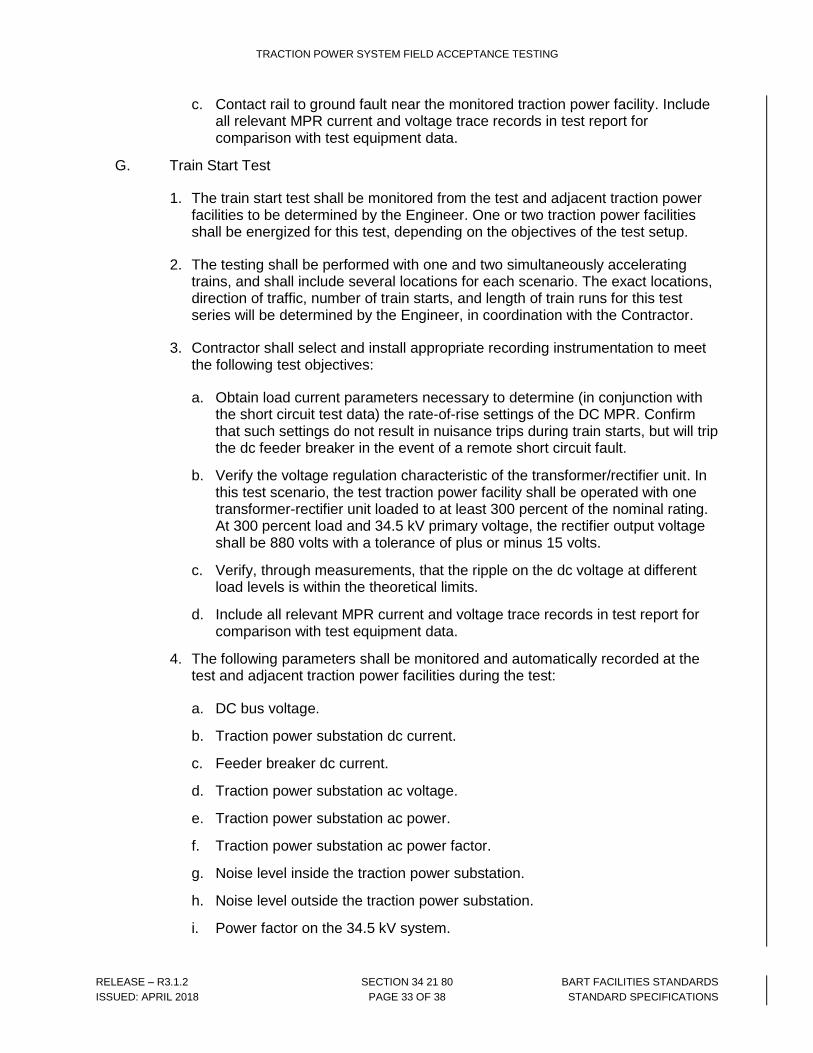
c. Contact rail to ground fault near the monitored traction power facility. Include all relevant MPR current and voltage trace records in test report for comparison with test equipment data.
G. Train Start Test
1. The train start test shall be monitored from the test and adjacent traction power facilities to be determined by the Engineer. One or two traction power facilities shall be energized for this test, depending on the objectives of the test setup.
2. The testing shall be performed with one and two simultaneously accelerating trains, and shall include several locations for each scenario. The exact locations, direction of traffic, number of train starts, and length of train runs for this test series will be determined by the Engineer, in coordination with the Contractor.
3. Contractor shall select and install appropriate recording instrumentation to meet the following test objectives:
a. Obtain load current parameters necessary to determine (in conjunction with the short circuit test data) the rate-of-rise settings of the DC MPR. Confirm that such settings do not result in nuisance trips during train starts, but will trip the dc feeder breaker in the event of a remote short circuit fault.
b. Verify the voltage regulation characteristic of the transformer/rectifier unit. In this test scenario, the test traction power facility shall be operated with one transformer-rectifier unit loaded to at least 300 percent of the nominal rating. At 300 percent load and 34.5 kV primary voltage, the rectifier output voltage shall be 880 volts with a tolerance of plus or minus 15 volts.
c. Verify, through measurements, that the ripple on the dc voltage at different load levels is within the theoretical limits.
d. Include all relevant MPR current and voltage trace records in test report for comparison with test equipment data.
4. The following parameters shall be monitored and automatically recorded at the test and adjacent traction power facilities during the test:
a. DC bus voltage.
b. Traction power substation dc current.
c. Feeder breaker dc current.
d. Traction power substation ac voltage.
e. Traction power substation ac power.
f. Traction power substation ac power factor.
g. Noise level inside the traction power substation.
h. Noise level outside the traction power substation.
i. Power factor on the 34.5 kV system.

TRACTION POWER SYSTEM FIELD ACCEPTANCE TESTING
RELEASE – R3.1.2 SECTION 34 21 80 BART FACILITIES STANDARDS
ISSUED: APRIL 2018 PAGE 34 OF 38 STANDARD SPECIFICATIONS
H. Audible sound level test shall be performed in accordance with the following:
1. Verify the ambient sound level at each traction power facility site without trainset movement (i.e. under no-load conditions).
2. Verify that the sound generated from each traction power facility site does not exceed contract requirements with a) the maximum number of fully loaded trainsets (for normal operation) simultaneously accelerated to attain maximum permitted civil line speed (in designated test area); b) all traction power facilities normally connected to the contact rail system and c) the contact rail system configured per the approved design.
3. Refer to Section 34 21 01, General Requirements for the Traction Power System, for noise level criteria.
I. Infrared thermographic inspection shall be performed in accordance with the following:
1. Perform thermographic inspection, at each traction power facility, to check for manufacturing/installation flaws.
2. Inspection / test shall be undertaken a) after energizing and loading the equipment for a sufficient time to raise the equipment temperature to operating limits, and b) the maximum number of fully loaded trainsets for normal operation shall be in operation.
3. Submit dated and site specific digital image and video files with the test report in electronic format on a flash drive for each traction power facility.
J. Miscellaneous tests shall be performed in accordance with the following:
1. Telephone System Tests
a. Perform telephone system tests in accordance with Section 27 30 01, Telephone System.
2. Fire Detection and Alarm System Tests
a. Perform tests on the fire detection and alarm system in accordance with Section 28 31 00, Fire Detection and Alarm System.
3. Radio System Tests
a. Perform tests on the radio system in accordance with Section 27 70 10, Radio Amplifier System for Wayside Facilities.
4. Security System Tests
a. Perform tests on the access control, intrusion detection and video surveillance system of the AC and DC houses, to confirm its proper operations in accordance with Section 28 10 01, Access Control System, and Section 28 41 29, Closed Circuit Television System.

TRACTION POWER SYSTEM FIELD ACCEPTANCE TESTING
RELEASE – R3.1.2 SECTION 34 21 80 BART FACILITIES STANDARDS
ISSUED: APRIL 2018 PAGE 35 OF 38 STANDARD SPECIFICATIONS
3.07 COMMISSIONING
A. General
1. The Contractor shall provide all necessary field support to assist District commissioning of new TPSS’s following successful completion of equipment functional testing described herein. Commissioning will be done during weekends, including system non-revenue periods as described in Contract Specifications Section 01 11 00, Summary of Work.
B. Emergency and Transfer Trip (ETTS) System function and indications.
1. The Contractor shall provide support to District staff as needed to terminate Platform Trip System connections at the train control room adjacent to the TPSS being commissioned.
2. Following connection of all Platform Trip circuits, the Contractor shall assist as needed in conducting live tests of the Platform Trip System to verify correct system operation.
3. The Contractor shall provide support to District staff as needed to terminate Transfer Trip connections at GBS’s adjacent to the TPSS being commissioned.
4. Following connection of all Transfer Trip circuits, the Contractor shall assist as needed in conducting live tests of the Transfer Trip system to verify correct system operation.
5. Connection and testing of the transfer trip system circuits may occur at a time later than connection and testing of the Platform Trip System and Emergency Trip System circuits.
END OF SECTION 34 21 80
ATTACHMENT FOLLOWS

TRACTION POWER SYSTEM FIELD ACCEPTANCE TESTING
RELEASE – R3.1.2 SECTION 34 21 80 BART FACILITIES STANDARDS
ISSUED: APRIL 2018 PAGE 36 OF 38 STANDARD SPECIFICATIONS
Attachment 34 21 80 – A
Date
Correspondence Number
Originator’s Name and Address
Recipient’s Name and Title
Subject: Test Record Certification
Dear
I hereby certify that:
• The tests included in this submittal were conducted in accordance with the approved test procedure(s).
• The attached test results are complete, accurately reflect the conditions and empirical data noted during the execution of the test, and have been back checked by the Test Director / Manager.
• The test results have been evaluated and the unit(s) under test met the acceptance criteria as set forth in the approved test procedure(s).
• There are no outstanding test discrepancies associated with the submitted test records.
Sincerely,
Name:
Title:
Contact Details:

TRACTION POWER SYSTEM FIELD ACCEPTANCE TESTING
RELEASE – R3.1.2 SECTION 34 21 80 BART FACILITIES STANDARDS
ISSUED: APRIL 2018 PAGE 37 OF 38 STANDARD SPECIFICATIONS
Attachment 34 21 80 – B
Test Issues Tracking Log
ITEM # DATE
REFERENCE DOCUMENTS
EQUIPMENT/ CABLE
IDENTIFIER ISSUE LOCATION RESPONSIBLE
PARTY RESPONSE
DISPOSITION AFTER
RETEST/ REGRESSION
TESTING STATUS DATE
VERIFIED

TRACTION POWER SYSTEM FIELD ACCEPTANCE TESTING
RELEASE – R3.1.2 SECTION 34 21 80 BART FACILITIES STANDARDS
ISSUED: APRIL 2018 PAGE 38 OF 38 STANDARD SPECIFICATIONS
Attachment 34 21 80 – C
Test Metrics Log
TEST DOCUMENTATION SUBMITTAL STATUS TEST STATUS ISSUES COMMENT
CATEGORY DOCUMENT REFERENCE SUBMITTED
IN REVIEW APPROVED REJECTED PASSED FAILED
RETEST/ REGRESSION OPEN CLOSED