3/4 lvl reinforced joining guide - andersen windows lvl reinforced joining guide use caution when...
TRANSCRIPT

3/4" LVL Reinforced Joining Guide
Use caution when working at elevated heights and around unit openings. Follow manufacturer’s instructions for safe use of ladder and/or scaffolding. Failure to do so may result in injury or death.
Follow manufacturer’s instructions for safe operation of hand/power tools. Always wear safety glasses. Failure to do so may result in injury and/or product damage.
Impact Resistant Glass used by Andersen is not hurricane proof or shatter proof, and may not offer a high level of security. Proper installation of window and door units with impact resistant glass is as important to product performance as the glass. Every assembly and installation is different (windloads, structural support, etc.), and Andersen strongly recommends consultation with an Andersen supplier or an experienced contractor, architect, or structural engineer prior to the assembly and installation of any Andersen product. Andersen has no responsibility in regard to the post-manufactured assembly and installation of Andersen products.
Congratulations! You have just purchased one of the many fine Andersen® products. Proper assembly, installation and maintenance are essential if the benefits of your Andersen product are to be fully attained. Therefore, please read and follow this Instruction Guide completely. If your abilities do not match this procedure’s requirements, contact an experienced contractor. You may direct any questions about this or other products to your local Andersen dealer, found in the Yellow Pages under “Windows” or call Andersen WindowCare® service center at 1-888-888-7020 Monday through Friday, 7 a.m. to 7 p.m. Central Time and Saturday, 8 a.m. to 4 p.m. Central Time. Thank you for choosing Andersen.
• Andersen® Installation Flanges DO NOT take the place of standard window and door flashing. Unit must be properly flashed and sealed with sealant, and full width drip cap for protection against water and air infiltration. Use non-reflective flashings. Highly reflective flashing tapes can raise the surface temperature of the vinyl to the point where vinyl deformation and product damage may occur.
• Donotapplyanytypeoffilmtoglass.Thermalstressconditionsresultinginglassdamagecouldoccur.
• Useofmovableinsulatingmaterialssuchaswindowcoverings,shutters,andothershadingdevicesmaydamageglass and/or vinyl. In addition, excessive condensation may result causing deterioration of windows and doors.
Unless specifically ordered, Andersen windows and doors are not equipped with safety glass, and if broken, could fragment causing injury. Many laws and building codes require safety glass in locations adjacent to or near doors. Andersen windows are available with safety glass that may reduce the likelihood of injury when broken. Information on safety glass is available from your local Andersen dealer.
0005383 BC Revised 12/17/07
3/4" LVL Reinforced Joining Guide (2-Way Horizontal and Vertical Joining)for Andersen® 400/200 Series Casement, Awning, Picture, and 400 Series Flexiframe® Windows
Windows and doors can be heavy. Use safe lifting techniques and a reasonable number of people with enough strength to lift, carry and install window and door products to avoid injury and/or product damage.
“Andersen” and al l other marks where denoted are trademarks of Andersen Corporation. ©2004-2007 Andersen Corporation. Al l r ights reser ved.
1

Component Identification
• Usethisguideforjoiningunitshorizontallyand vertically.• 2-Waycombinationsusing3/4"LVLJoiningStripmustbe
assembledunit-by-unitinroughopening.LVLReinforcedJoiningmustbeusedforalljoins.
2-Way Horizontal and Vertical Joining
Parts Included (More than one kit required for two way joining)(1) Instruction Guide(1) 3/4"LVLJoiningStrip(4-9/16"or6-9/16"wallconstruction)(2) LoadTransferBracket(4-9/16"or6-9/16")(1) Exterior Trim Strip(1) Screw Pack(2)IntersectionBracket
Tools and Supplies•SafetyGlasses•TapeMeasure•Pencil•Level•Hammer•DeepJawClamps•UtilityKnife•ElectricDrill•CaulkGun
Exterior Trim Strip
3/4"LVLJoiningStrip
LoadTransferBracket
• UnitsmustbeinstalledaccordingtoinstallationguidesusingJambClipsorproductwillnotmeetdesignatedperformance levels.
• Ventingunitsarepackagedwithtemporaryoperator/lockhandles.Permanentoperator/lockhardwareisavailable in various styles and finishes from your local Andersen dealer.
• DO NOTapplyExtensionJambspriortounitinstallation.
•Chisel•Sealant•Side-Cutters/Pliers•SmallPryBar•WoodShims•PowerSaw•IsopropylAlcohol•WoodBlock•3/32"DrillBit
Metal fasteners and components may corrode when exposed to preservative-treated and/or fire-retardant treated lumber. Obtain and use the appropriate metal fasteners and hardware as called out by the installation guide to fasten unit to any rough opening made from preservative-treated and fire-retardant treated lumber. Failure to use the appropriate materials for the installation may cause a failure resulting in injury, property or product damage.
(Required to complete reinforced joining installation)
IntersectionBracket
4-9/16"
6-9/16"
4-9/16" 6-9/16"Or
Or
Exterior View
Additional Parts Required•DripCap(fullwidth)
3/4" LVL Reinforced Joining Guide
2
PSF
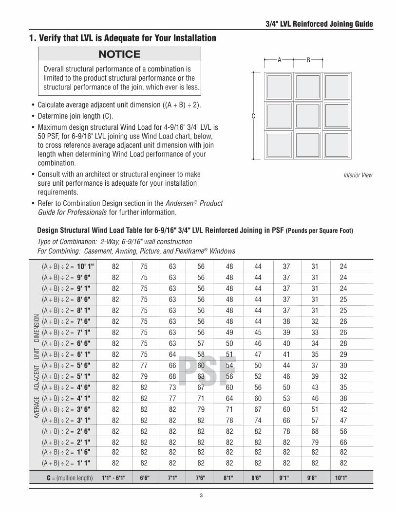
(A + B) ÷ 2 = 10' 1" 82 75 63 56 48 44 37 31 24(A + B) ÷ 2 = 9' 6" 82 75 63 56 48 44 37 31 24(A + B) ÷ 2 = 9' 1" 82 75 63 56 48 44 37 31 24(A + B) ÷ 2 = 8' 6" 82 75 63 56 48 44 37 31 25(A + B) ÷ 2 = 8' 1" 82 75 63 56 48 44 37 31 25(A + B) ÷ 2 = 7' 6" 82 75 63 56 48 44 38 32 26(A + B) ÷ 2 = 7' 1" 82 75 63 56 49 45 39 33 26(A + B) ÷ 2 = 6' 6" 82 75 63 57 50 46 40 34 28(A + B) ÷ 2 = 6' 1" 82 75 64 58 51 47 41 35 29(A + B) ÷ 2 = 5' 6" 82 77 66 60 54 50 44 37 30(A + B) ÷ 2 = 5' 1" 82 79 68 63 56 52 46 39 32(A + B) ÷ 2 = 4' 6" 82 82 73 67 60 56 50 43 35(A + B) ÷ 2 = 4' 1" 82 82 77 71 64 60 53 46 38(A + B) ÷ 2 = 3' 6" 82 82 82 79 71 67 60 51 42(A + B) ÷ 2 = 3' 1" 82 82 82 82 78 74 66 57 47(A + B) ÷ 2 = 2' 6" 82 82 82 82 82 82 78 68 56(A + B) ÷ 2 = 2' 1" 82 82 82 82 82 82 82 79 66 (A + B) ÷ 2 = 1' 6" 82 82 82 82 82 82 82 82 82(A + B) ÷ 2 = 1' 1" 82 82 82 82 82 82 82 82 82
1. Verify that LVL is Adequate for Your Installation
• Calculateaverageadjacentunitdimension((A+B)÷2).• Determinejoinlength(C).• MaximumdesignstructuralWindLoadfor4-9/16"3/4"LVLis
50PSF,for6-9/16"LVLjoininguseWindLoadchart,below,to cross reference average adjacent unit dimension with join lengthwhendeterminingWindLoadperformanceofyourcombination.
• Consultwithanarchitectorstructuralengineertomakesure unit performance is adequate for your installation requirements.
• RefertoCombinationDesignsectionintheAndersen ® Product Guide for Professionals for further information.
Design Structural Wind Load Table for 6-9/16" 3/4" LVL Reinforced Joining in PSF (Pounds per Square Foot)
Type of Combination: 2-Way, 6-9/16" wall constructionFor Combining: Casement, Awning, Picture, and Flexiframe® Windows
Aver
Age
Ad
jACe
nt
Uni
t
dim
enSi
on
C = (mullion length)
Overall structural performance of a combination is limited to the product structural performance or the structural performance of the join, which ever is less.
Interior View
BA
C
1'1" - 6'1" 6'6" 7'1" 7'6" 8'1" 8'6" 9'1" 9'6" 10'1"
3/4" LVL Reinforced Joining Guide
3
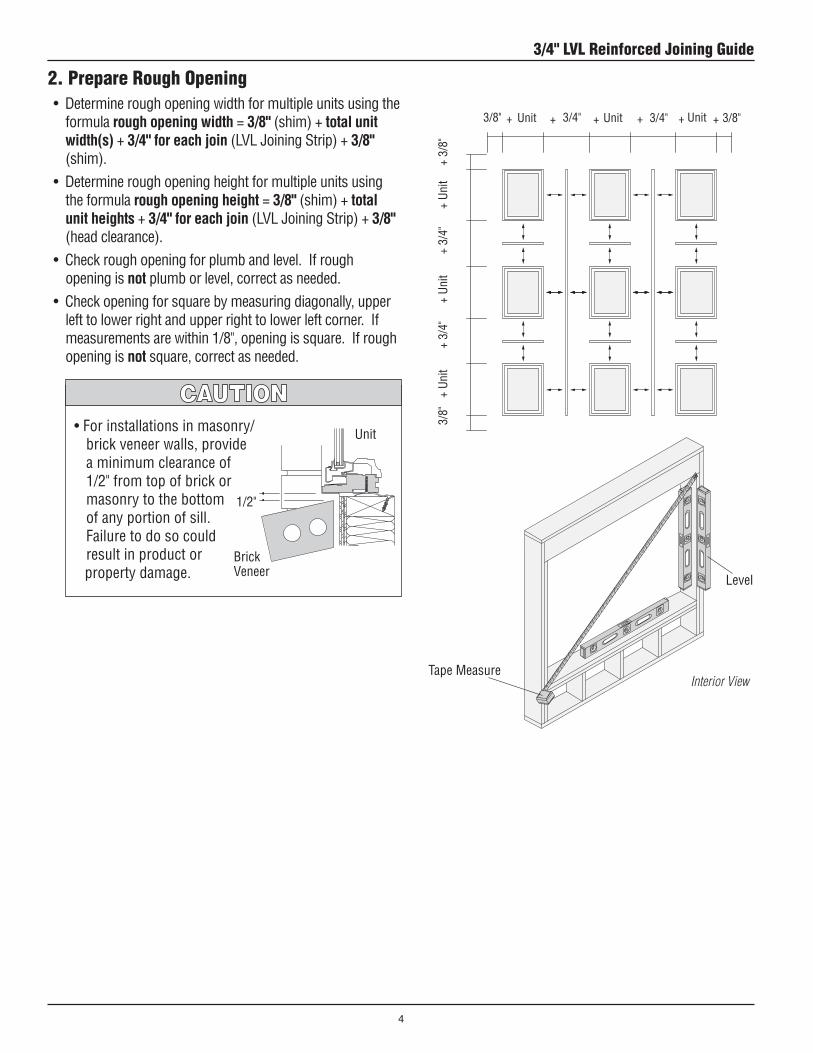
2. Prepare Rough Opening•Determineroughopeningwidthformultipleunitsusingthe
formula rough opening width = 3/8" (shim)+ total unit width(s) + 3/4" for each join(LVLJoiningStrip)+ 3/8" (shim).
•Determineroughopeningheightformultipleunitsusingthe formula rough opening height = 3/8" (shim)+total unit heights + 3/4" for each join(LVLJoiningStrip)+ 3/8" (head clearance).
•Checkroughopeningforplumbandlevel.Ifroughopening is not plumb or level, correct as needed.
•Checkopeningforsquarebymeasuringdiagonally,upperleft to lower right and upper right to lower left corner. If measurementsarewithin1/8",openingissquare.Ifroughopening is not square, correct as needed.
Interior View
•Forinstallationsinmasonry/brick veneer walls, provide a minimum clearance of 1/2"fromtopofbrickormasonry to the bottom of any portion of sill. Failure to do so could result in product or property damage.
1/2"
BrickVeneer
Unit
+ Unit 3/4" Unit 3/4"3/8" 3/8"Unit+ + + + +
3/8"
+
Unit
+3/
4"
+
Unit
+3/
4"
+
Unit
+
3/8
"
Tape Measure
Level
3/4" LVL Reinforced Joining Guide
4
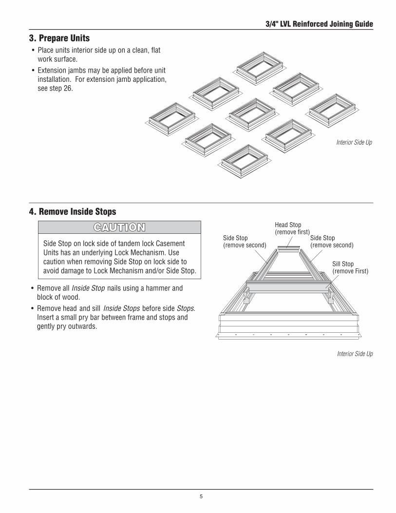
3. Prepare Units• Placeunitsinteriorsideuponaclean,flat
work surface.•Extensionjambsmaybeappliedbeforeunit
installation. For extension jamb application, see step 26.
• Removeall Inside Stop nails using a hammer and block of wood.
• Removeheadandsill Inside Stops before side Stops. Insert a small pry bar between frame and stops and gently pry outwards.
Side Stop on lock side of tandem lock Casement UnitshasanunderlyingLockMechanism.Usecaution when removing Side Stop on lock side to avoiddamagetoLockMechanismand/orSideStop.
Head Stop (remove first)
Side Stop (remove second)
Sill Stop (remove First)
Side Stop (remove second)
4. Remove Inside Stops
Interior Side Up
Interior Side Up
3/4" LVL Reinforced Joining Guide
5

• CutorremoveInstallation Flange(s) on head, sill, or sides being joined, as appropriate for joined combination. See diagram. Cut Installation Flange flush with jamb.
5. Prepare Flanges
UtilityKnife
Installation Flange
OverlapInterior Side Up
Exterior View
Overlap
Overlap
3/4" LVL Reinforced Joining Guide
6

6. Determine Installation Sequence
1
4
2
5
3
6
1
2
3
4
5
6
• Determinesequenceofinstallation.Combinationsmust be constructed unit-by-unit in the rough opening beginning with the lower left unit as viewed from the exterior.
1
2
4
3
5
6
7
8
9
Six Unit Vertical Assembly
Six Unit Horizontal Assembly
Nine Unit Vertical AssemblyExample assembly used throughout guide.
3/4"LVLJoiningStrip
3/4"LVLJoiningStrip
3/4"LVLJoiningStrip
LapInstallationFlange Over LowerUnit
LapInstallationFlange Over LowerUnit
LapInstallationFlange Over LowerUnit
Exterior View
Exterior View
Exterior View
LapInstallationFlange Over LowerUnit
LapInstallationFlange Over LowerUnit
LapInstallationFlange Over LowerUnit
3/4"LVLJoiningStrip
3/4" LVL Reinforced Joining Guide
7

• Squareendcut3/4" LVL Joining Strip1/2"shorterthan length of units being joined.
• ReplicatefactoryendonLVL Joining Strip by removing3-1/2"ofwoodstriptomakeroomforJoining Bracket, using a chisel.
7. Prepare 3/4" LVL Joining Strips for Horizontal Joins
8. Attach 3/4" LVL Horizontal Joining Strips • Position3/4" LVL Joining Strip in dado on jamb and
center on unit. 3/4" LVL Joining Strip must not extend into side jamb dados.
• Fastenusing(3)1-3/8"screwsspacedevenlyalong3/4" LVL Joining Strip.
Side JambDado 1-3/8"Screw
3/4"LVLJoiningStrip
3/4"LVLJoiningStrips
Remove3-1/2"WoodStrip
Interior Side Up
3-1/2"
Interior Side Up
Chiseled end facing away from unit.3/4"LVLJoiningStripmust not extend into side jamb dado.
Head of Assembly
Sill of Assembly
3/4"LVLJoiningStrip
Square end cut to length.
3/4" LVL Reinforced Joining Guide
8

9. Apply Jamb Clips to Unit Sides Adjacent to Rough Opening
• SeediagramsonPage 10 for Jamb Clip quantity based onunittypeandsize.Jamb Clips are attached to head, sill, and/or side jambs of units that are adjacent to rough opening.
• PositionJamb Clips in dado on back side of jambs, longlegtointerior,extending1-1/8"abovejambs,asshown.
• PositionaJamb Clip in center of unit at head and sill, as shown on Page 10. Equally space Jamb Clips , according to unit dimension height, and fasten to unit using two #8 x 1" Screws.
• ProceedtoStep 10.
NumberofJambClipsand/orScrewsisbasedonamaximumunitstructuralperformanceDesignPressure(DP)Rating.UsecorrectnumberofJambClipsand/orScrewslisted.FailuretodosomayresultinlowerDPrating.
A minimum of one clip at head and at sill is required for each glass light on single, double and triple units. Failure to properly anchor using clips will adversely affect design pressure rating, product performance and may result in injury, product and/or property damage.
Casement/Awning Units
• ForPicture/Transom Window Units, go to Page 11.• ForFlexiframe® Units, go to Page 13.
1-1/8"
Interior
Exterior
Dado
#8x1"Screw
JambClip(LongLeg)
Interior Side Up
Standard Jamb Clip
Optional Jamb Clip (Sold Separately)
3/4" LVL Reinforced Joining Guide
9

9. Apply Jamb Clips (continued)
12"
12" 12"
12"
12"
12"
Height24-1/8" Height28-3/8"to48" Height52-13/16"to71-7/8"
Casement Side Jamb Clip Locations
Casement Head and Sill Jamb Clip Locations
CR,CN,C,CW,CX,CXW Single Units
Width24-1/8" Width28-3/8"to48" Width52-13/16"to71-7/8"
Awning Head, Sill, and Side Jamb Clip Locations
Center
Center
Center
Exterior Views
Exterior Views
Exterior Views
12" 12" 12" 12" 12" Center 12"
3/4" LVL Reinforced Joining Guide
10

#8x1-1/4"Screw
JambClip
9. Apply Jamb Clips (continued)
• DetermineJamb Clip quantity based on unitsizefromtablesonPage 12.
• PositionJamb Clips in dado on back side of jambs, long leg to interior, extending 1-1/8"abovejambs,asshown.Equallyspace Jamb Clips , according to unit dimension height/width, and fasten to jamb using two #8 x 1-1/4" Screws.
• ProceedtoStep 10.
InteriorExterior
6"max.
1-1/8"
Equally Spaced24"max. on center
Side Jamb
1-1/8"
Equally Spaced20"max. on center
Head/Sill
6"max.
JambClip
JambClip
1-1/8"
Interior
Exterior
Dado
#8x1-1/4"Screw(included)
JambClip(LongLeg)
Interior Side Up
Picture/Transom Window Units
Picture/Transom Window Units
Interior
Exterior
3/4" LVL Reinforced Joining Guide
11

PictureWindowDimensions&JambClipChart TransomWindowDimensions&JambClipChart
9. Apply Jamb Clips (continued)
UNIT DIM. DIM. CLIPS PER CLIPS PER DES. WIDTH HEIGHT HEAD/SILL SIDE JAMB
P5060 597/8" 717/8" 4 4P4560 5213/16" 717/8" 4 4P4060 48" 717/8" 3 4P3560 4013/16" 717/8" 3 4P3060 3515/16" 717/8" 3 4P5055 597/8" 6413/16" 4 4P4555 5213/16" 6413/16" 4 4P4055 48" 6413/16" 3 4P3555 4013/16" 6413/16" 3 4P3055 3515/16" 6413/16" 3 4P6050 717/8" 597/8" 4 3P5550 6413/16" 597/8" 4 3P5050 597/8" 597/8" 4 3P4550 5213/16" 597/8" 4 3P4050 48" 597/8" 3 3P3550 4013/16" 597/8" 3 3P3050 3515/16" 597/8" 3 3P6045 717/8" 5213/16" 4 3P5545 6413/16" 5213/16" 4 3P5045 597/8" 5213/16" 4 3P4545 5213/16" 5213/16" 4 3P4045 48" 5213/16" 3 3P3545 4013/16" 5213/16" 3 3P3045 3515/16" 5213/16" 3 3P6040 717/8" 48" 4 3P5540 6413/16" 48" 4 3P5040 597/8" 48" 4 3P4540 5213/16" 48" 4 3P4040 48" 48" 3 3P3540 4013/16" 48" 3 3P3040 3515/16" 48" 3 3P6035 717/8" 4013/16" 4 3P5535 6413/16" 4013/16" 4 3P5035 597/8" 4013/16" 4 3P4535 5213/16" 4013/16" 4 3P4035 48" 4013/16" 3 3P3535 4013/16" 4013/16" 3 3P3035 3515/16" 4013/16" 3 3P6030 717/8" 3515/16" 4 2P5530 6413/16" 3515/16" 4 2P5030 597/8" 3515/16" 4 2P4530 5213/16" 3515/16" 4 2P4030 48" 3515/16" 3 2P3530 4013/16" 3515/16" 3 2P3030 3515/16" 3515/16" 3 2
UNIT DIM. DIM. CLIPS PER CLIPS PER DES. WIDTH HEIGHT HEAD/SILL SIDE JAMB
CTR1510 17" 12" 2 1CTR1810 201/2" 12" 2 1CTR2010 241/8" 12" 2 1CTR2410 283/8" 12" 2 1CTR2810 311/2" 12" 2 1CTR2910 333/4" 12" 3 1CTR/PTR3010 3515/16" 12" 3 1CTR3410 403/4" 12" 3 1CTR3510 4013/16" 12" 3 1CTR/PTR4010 48" 12" 3 1PTR4510 5213/16" 12" 4 1CTR4810 561/2" 12" 4 1PTR5010 597/8" 12" 4 1CTR5210 623/4" 12" 4 1PTR5510 6413/16" 12" 4 1CTR51110 715/8" 12" 4 1CTR/PTR6010 717/8" 12" 4 1
3/4" LVL Reinforced Joining Guide
12

Interior
Exterior
Dado
9. Apply Jamb Clips (continued)
• DetermineJamb Clip locations from diagrams.• PositionJamb Clips in dado on back side of jambs,
longlegtointeriorandextending1-1/8"abovejambs.Fasten using two #8 x 1-1/4" Screws.
Use one clip at head and at sill for each glass light on single, double, and triple units. Failure to do so will adversely affect design pressure rating, product performance and may result in injury, product and/or property damage.
#8x1-1/4"Screw
JambClip(LongLeg)
Arch UnitFlexiframe® Unit
12"max.
24"max.
1-1/8"
6"max.
24"max.sidejamb 20"max.headjamb/sill
InteriorExterior
1-1/8"
InteriorExterior
JambClip JambClip
Flexiframe® Units
3/4" LVL Reinforced Joining Guide
13

Metal fasteners and components may corrode when exposed to preservative-treated and/or fire-retardant treated lumber. Obtain and use the appropriate metal fasteners and hardware as called out by the installation guide to fasten unit to any rough opening made from preservative-treated and fire-retardant treated lumber. Failure to use the appropriate materials for the installation may cause a failure resulting in injury, property or product damage.
• Applya1/4"beadofsealanttobacksideofInstallation Flange.
10. Install First Window Unit
Windows and doors can be heavy. Use safe lifting techniques and a reasonable number of people with enough strength to lift, carry and install window and door products to avoid injury and/or product damage.
Interior View
JambClip
• PositionLoad Transfer Bracket against rough opening and3/4"LVL Joining Strip at head. Fasten Load Transfer Bracketto3/4"LVL Joining Strip using eight #8x3/4"screws.Useseven#8x1"screwstofastenLoad Transfer Bracket to rough opening .
• FastenJamb Clips to rough opening using 1" Screws.
LoadTransferBracket
• Liftunitintoleftsideofroughopeningfromtheexterior, supporting unit at all times until fully secured.
• Shimunit3/8"fromroughopeningatsideandsilltokeep unit level due to Load Transfer Bracket on adjacent units.
• Checkleftsidejambforplumb,level,andsquare.Correct as needed using shims.
Shims
#8x1"Screws(1"minimumintoroughopening)
#8x3/4"Screws(intoLVLjoiningstrip)
Unit assembly illustrated throughout this guide representsacontinuousvertical3/4"LVLJoiningStrip.
#8x1"Screws(minimum into rough opening)
3/4"LVLJoiningStrip
Chiseled side up
Continuous 3/4"LVLJoiningStrip
3/4" LVL Reinforced Joining Guide
14

11. Install Second Window Unit
• Apply1/4"beadofsealanttothebacksideofInstallation Flange.
• Positionsecondunitoverfirstunit,overlappingupper unit Installation Flange over lower unit Installation Flange to the exterior. Seat unit into aluminum legs on LVL Joining Strip.
• Clampunitstogether,fromtheinterior,usingsurfaceprotectors.
• Shimunit3/8"fromroughopeningatsidetomakesure unit remains level due to Load Transfer Bracket on adjacent units.
• Checkunitforplumblevelandsquare.Correctasneeded using shims.
• Locateone2-1/2"Screw3"fromeachcorneronsillofupperunit.Spaceadditionalscrewsevery12",alternating between head of lower unit and sill of upper unit.
• FastenJamb Clips toroughopeningusing#8x1"Screws minimum.
• PositionLoad Transfer Bracket against rough opening and3/4"LVL Joining Strip at head. Fasten Load Transfer Bracketto3/4"LVL Joining Strip using eight #8x3/4"screws.Useseven#8x1"screwstofastenLoad Transfer Bracket to rough opening.
• Exteriornoseofunitsandsidejambsmustbeflush full length. If not flush, units will not be properly sealed which may result in water infiltration.
• Excesstighteningofclampsmaymarsurface.• UpperunitInstallationFlangemustoverlaplower
unit Installation Flange to the exterior. Failure to do so may lead to water infiltration causing product or property damage.
2-1/2"Screws
Clamp
Interior View
LoadTransferBracket
Interior View
3"12"
12"
3/4"LVLJoiningStrip
AluminumLegs
UnitJamb
Exterior View(Circle)
First Unit Installation Flange
Second Unit Installation Flange
Overlap
3/4" LVL Reinforced Joining Guide
15

12. Install Third Window Unit
• Apply1/4"beadofsealanttothebacksideofInstallation Flange.
• Positionthirdunitoversecondunit,overlappingupper unit Installation Flange over lower unit Installation Flange to the exterior. Exterior nose of units and side jambs must be flush full length.
• Clampunitstogether,fromtheinterior,usingsurfaceprotectors.
• Shimunit3/8"fromroughopeningatsideandheadto keep level due to Load Transfer Bracket on adjacent units.
• Checkleftsidejambforplumb,level,andsquare.Correct as needed using shims.
• PresssideInstallation Flange tight to rough opening. • FastenJamb Clips toroughopeningusing1"Screws.• Locateone2-1/2"screw,3"fromeachcorner,onsill
ofupperunit.Spaceadditionalscrewsevery12",alternating between head of lower unit and sill of upper unit.
• Exteriornoseofunitsandsidejambsmustbeflush full length. If not flush, units will not be properly sealed which may result in water infiltration.
• Excesstighteningofclampsmaymarsurface.• UpperunitInstallationFlangemustoverlaplower
unit Installation Flange to the exterior. Failure to do so may lead to water infiltration causing product or property damage.
Interior View
2-1/2"Screw
JambClip
1"Screws
Interior View
Clamp
12"
3"
3/4" LVL Reinforced Joining Guide
16

14. Attach 3/4" LVL Vertical Joining Strip • Position3/4" LVL Joining Strip in dado of installed units
flush with end of unit frames.• Fasten3/4" LVL Joining Strip usingthree1-3/8"screws
located at center of installed units. Avoid locating screws near Tandem Lock Link Bar. Screws must be located to the interior side of Lock Link Bar, at 15° to avoid hitting extension jamb kerf.
1-3/8"Screws
3/4"LVLJoiningStrip
Interior Views
Chiseled end facing away from units.
Wheninstallingventingunits,install2-1/2"screwstotheinteriorsideofTandemLockLinkBar.Failureto do so may result in improper function of lock.
3/4"LVLJoiningStrip
TandemLockLinkBar 2-1/2"Screw
ExtensionJambKerf
13. Prepare 3/4" LVL Joining Strip for Vertical Joins• Squareendandcut3/4" LVL Joining
Strip equal to the height of unit combination.
• Replicatethefactorycutendof3/4" LVL Joining Stripbyremoving3-1/2"ofwood strip by chiseling to make room for Load Transfer Bracket.
3/4"LVLJoiningStrip
Remove3-1/2"Wood Strip
Square end cut to length.
3-1/2"
LoadTransferBracket
3/4" LVL Reinforced Joining Guide
17

Metal fasteners and components may corrode when exposed to preservative-treated and/or fire-retardant treated lumber. Obtain and use the appropriate metal fasteners and hardware as called out by the installation guide to fasten unit to any rough opening made from preservative-treated and fire-retardant treated lumber. Failure to use the appropriate materials for the installation may cause a failure resulting in injury, property or product damage.
15. Attach 3/4" Joining Bracket to Head and Sill
• PositionLoad Transfer Bracket against rough opening and 3/4" LVL Joining Strip at sill. Fasten Load Transfer Bracket to 3/4" LVL Joining Strip using eight #8x3/4"screws.Useseven#8x1"screwstofastenLoad Transfer Bracket to rough opening.
• Position3/4" Joining Bracket against rough opening and 3/4" LVL Joining Strip at head. Fasten 3/4" Joining Bracket to 3/4" LVL Joining Strip using eight #8x3/4"screws.Useseven#8x1"screwstofasten3/4" Joining Bracket to rough opening.
LoadTransferBracket(Sill)
3/4"LVLJoiningStrip
#8x3/4"Screws(IntoLVLJoiningStrip)
#8x1"Screws(1"MinimumIntoRoughOpening)
Interior View
Sill
3/4" LVL Reinforced Joining Guide
18

16. Install and Join Next Sequence of Units• Installandjointhenextsequenceofunitsfollowing
Steps 10-12, omitting the installation of Load Transfer Bracket.
• Fastenunitsidejambsto3/4" LVL Joining Strips using 2-1/2"screws.Locateonescrew3"fromeachcornerandadditionalscrewsevery12",alternatingbetweenadjacent units.
2-1/2"Screws
2-1/2"Screws
#8x1"Screws(1"minimumintorough opening)
2-1/2"Screws
Clamp
1st Unit and LVL Joining Strip Installation, Omitting Load Transfer Bracket (Step 10)
3rd Unit Installation (Step 12)
Wheninstallingventingunits,install2-1/2"screwstotheinteriorsideoftheTandemLockLinkBar.Failure to do so may result in improper function of lock.
3/4"LVLJoiningStrip
TandemLockLinkBar 2-1/2"Screw
ExtensionJambKerf
Interior View
Interior View
Interior View
15°
2nd Unit and LVL Joining Strip Installation, Omitting Load Transfer Bracket (Step 11)
12"3"
JambClip
3/4" LVL Reinforced Joining Guide
19

• Install3/4" LVL Vertical Joining Strip following Steps 13-15.
17. Attach 3/4" LVL Vertical Joining Strip
3/4"LVLJoiningStrip
Interior View
#8x3/4"Screws(intoLVLjoiningstrip)
#8x1"Screws(1"minimumintoroughopening)
Interior View
1-3/8"Screws
3/4" LVL Reinforced Joining Guide
20
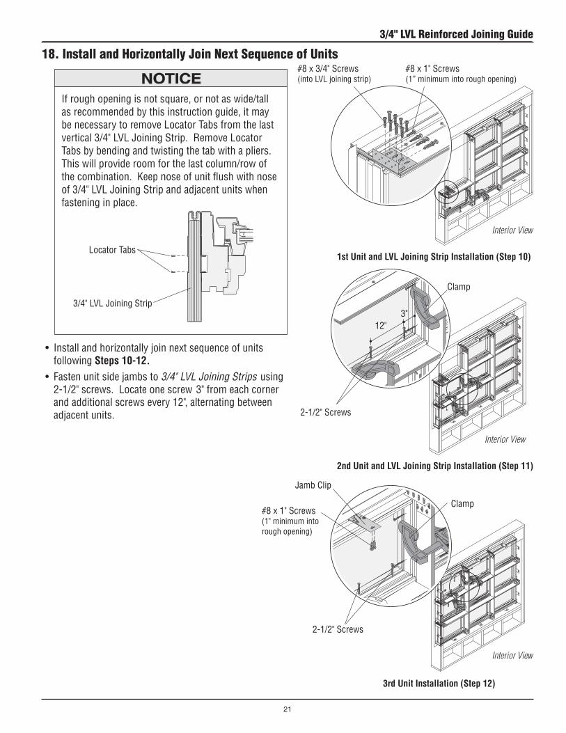
18. Install and Horizontally Join Next Sequence of Units
• Installandhorizontallyjoinnextsequenceofunitsfollowing Steps 10-12.
• Fastenunitsidejambsto3/4" LVL Joining Strips using 2-1/2"screws.Locateonescrew3"fromeachcornerandadditionalscrewsevery12",alternatingbetweenadjacent units.
Interior View
If rough opening is not square, or not as wide/tall as recommended by this instruction guide, it may benecessarytoremoveLocatorTabsfromthelastvertical3/4"LVLJoiningStrip.RemoveLocatorTabs by bending and twisting the tab with a pliers. This will provide room for the last column/row of thecombination.Keepnoseofunitflushwithnoseof3/4"LVLJoiningStripandadjacentunitswhenfastening in place.
#8x1"Screws(1” minimum into rough opening)
#8x3/4"Screws(intoLVLjoiningstrip)
2-1/2"Screws
2-1/2"Screws
#8x1"Screws(1"minimumintorough opening)
LocatorTabs
3/4"LVLJoiningStrip
Interior View
Interior View
Clamp
Clamp
12"3"
1st Unit and LVL Joining Strip Installation (Step 10)
3rd Unit Installation (Step 12)
2nd Unit and LVL Joining Strip Installation (Step 11)
JambClip
3/4" LVL Reinforced Joining Guide
21

• CleansurfaceofTrim Strip Receivers and vinyl surface of unit for proper adhesion using isopropyl alcohol.
• CutVertical Exterior Trim Strips equal to unit height.• Applyacontinuous,1/4"beadofsealant,fulllength,
along edges of Vertical Trim Strip Receiver where receiver and unit jambs meet.
• Applysealanttovoidsatintersectionof3/4" LVL Joining Strips.
Initial positioning of Exterior Trim Strip is important because it is very difficult to remove once inserted.
• PositionedgeofverticalExterior Trim Strip flush with top of unit and press into Trim Strip Receiver, by hand, from top to bottom. Pound in place using a hammer and wood block. Repeat for additional Vertical Exterior Trim Strip.
#8x3/4"Screws
20. Apply Trim Strips
• PositionIntersection Brackets at each 90° corner at four-way 3/4" LVL Joining Strip intersection.
• FastenIntersection Bracketsusing#8x3/4"screws.
19. Attach Intersection Brackets at Unit Intersections
Intersection Bracket
Interior View
Exterior Trim Strips running continuously should be applied first. Fill voids at intersections with sealant and butt sectioned Exterior Trim Strips tight against continuous Exterior Trim Strips. Failure to do so may lead to water infiltration causing product or property damage.
Sealant
VerticalTrimStripExterior View
LVLJoiningStrip
3/4"LVLJoiningStrip
Fill voids at intersections.
Caulk Gun
Exterior View
3/4" LVL Reinforced Joining Guide
22

20. Apply Trim Strips (continued)• CutHorizontal Exterior Trim Strips to fit tight in between
Vertical Exterior Trim Strips.• Applyacontinuous,1/4"beadofsealant,fulllength,
along edges of Horizontal Trim Strip Receiver where receiver and unit jambs meet.
• Applysealant,3"fromintersection,indadosonHorizontal Trim Strip Receivers.
Initial positioning of Exterior Trim Strip is important because it is very difficult to remove once inserted.
• PositionendofhorizontalExterior Trim Strip tight to vertical Exterior Trim Strip at intersection and press, by hand, into Trim Strip Receiver. Pound in place using a hammerandwoodblock.RepeatforotherhorizontalExterior Trim Strip.
HorizontalTrimStrip
Exterior View
Sealant
3"
Caulk Gun
3/4" LVL Reinforced Joining Guide
23

• ApplysealanttovoidsattheendsofallExterior Trim Strips next to rough opening.
21. Apply Sealant
Exterior View
Sealant
Caulk Gun
Caulk Gun
22. Apply Full Width Drip Cap• Applysealantattoponly.Quicklyplacefull
width drip cap in sealant, centering over unit(s).
Full Width DripCap
Sealant
Exterior View
3/4" LVL Reinforced Joining Guide
24

24. Apply Flashing Tape
• Thisinstructionstepdepictsoneofmanyoptionsforproperflashing.• Moistureinfiltrationproblemsinanytypeofbuildingcanbereducedbyproperlyflashingand/orsealingaround
all building openings, including windows and doors. Proper flashing under and around window and door openings can reduce moisture problems, but the performance of any building system depends upon the design and construction of the building system in its entirety, which should address local environment, climate, building codes and product and material limitations. The design and installation of flashing and sealing systems are the responsibility of the architect, contractor, installer, and/or the manufacturer of the building exterior specified for the project.
Exterior View
Flashing Tape
• ApplyflashingtapeoverInstallation Flange at sill.
• ApplyflashingtapeoverInstallation Flange at sides, overlapping flashing tape at sill.
• ApplyflashingtapeoverInstallation Flange at head, overlapping flashing tape at sides.
Sill(apply first)
Sides(apply second)
Head (apply third)
23. Reapply Inside Stops
• PositionsideInside Stops first, then head and sill Inside Stops in frame groove and reapply by tacking intoplaceusing1-1/2"(4d)finishnails.Leaveapproximately1/8"ofnailheadexposedtoassistinremoval of Inside Stops for finishing.
When reapplying Side Stop on lock side of tandem LockCasementUnits,nailthroughexistingholes.Failure to do so could result in damage to underlying lock mechanism.
Head Stop (apply second)
Side Stop (apply first)
Sill Stop (apply second)
Side Stop (apply first)
Interior Side Up
3/4" LVL Reinforced Joining Guide
25

25. Insulate and Seal Unit
• Insulatebetweenframeandroughopeningonallsides. DO NOT over pack batt insulation or overfill with insulation, bowed jambs may result.
•Cleanandprimearoundoutsideofunitwherebackerrod and sealant will be applied using isopropyl alcohol.
• Applybackerrodandsiliconesealantaroundexteriorperimeter of window after siding (or other finish) is applied.
• Wheninsulatingbetweentheunitframeandrough opening, DO NOT over pack batt insulation oroverfillwithexpandablefoam.Bowedjambsmay result causing product performance problems and/or incorrect operation of unit.
• Aminimumspaceof1/4"isrequiredaroundexterior perimeter of unit between the frame and exterior finish material to allow for material expansion.
• Masonry/BrickVeneerinstallationsrequireaminimum1/2"spacealongthesilland1/4"spacearound remaining perimeter to allow for settling and expansion.
Caulk Gun
Exterior View
Sealant
BackerRod
3/4" LVL Reinforced Joining Guide
26

26. Apply Extension Jambs
SillExtensionJamb
JambClip
Interior Trim Stop
RippingofExtensionJambsmayberequiredtofitnonstandard wall depths. Contact your Andersen® dealer for further information.
• Drill3/32"holes,12"-18"apart,througheachExtension Jamb on back side of kerf.
• Start#8x1-1/4"screwsinholes.• Positionhead, sillandsideExtension Jambs on frame.
Fasten center screw into each Extension Jamb using a power drill with Phillips extension.
• Squarehead, sillandsideExtension Jambs tounit.Drill3/32"holes1-1/4"deepthroughheadandsillExtension Jambs and into end of Side Extension Jamb at each corner.
• Fastencornersusing#8x1-1/2"screws.Omitcornerscrew and shim Extension Jambs tight, at corners, where 3/4" LVL Joining Strip is present.
• FastenremainingscrewsinExtension Jambs.• ShimbetweenExtension Jambs and rough opening.• FacenailExtension Jambs to rough opening at shims.
#8x1-1/4"Screw
SillExtensionJamb
SideExtensionJamb
#8x1-1/2"Screw
#8x1-1/4"Screw
HeadExtensionJamb
SideExtensionJamb
SillExtensionJamb
#8x1-1/2"Screw
Center Screw
RippingofExtensionJambsmayberequiredtofitnonstandard wall depths. Contact your Andersen® dealer for further information.
Exterior
Interior Views
Exterior
Drill3/32"Holes
Phillips Screwdriver
Phillips Screwdriver
3/4" LVL Reinforced Joining Guide
27

MAINTENANCEImmediately sand and refinish any interior wood thatbecomes stained or mildewed to prevent further discoloration and/or damage. For further information,contact your local Andersen dealer.Dealerscanbefound in the Yellow Pages under Windows.
Finishing, Cleaning, and Maintenance Instructions
INTERIOR FINISHING Read and follow finishing manufacturer’s instructions
and warnings on each container of finish material for priming, painting, staining, and varnishing.
CLEANING Clean exterior frame, sash members, and insect
screens using a mild detergent-and-water solution and a soft cloth or brush. DO NOT use abrasive cleaners or solutions containing corrosive solvents. For persistent dirt or grime, use a nonabrasive cleanser or a mixture of water and alcohol or ammonia.
• DO NOT expose unfinished wood to high moisture conditions, excessive heat or humidity. Finish interior wood surfaces immediately after installation. Unfinished wood surfaces will discolor, deteriorate, and/or may bow and split.
• DO NOT stain or paint weatherstrip, silicone beads, vinyl,glass,orhardware.Damagetoproductmayoccur and unit operation may be impaired.
• Acidsolutionsusedtowashmasonry/concretewilldamage glass, fasteners, hardware, and metal flashing. If these solutions are used, follow the acid solution manufacturer's instructions carefully. Protect and/or cover Andersen products during the cleaning process to prevent acid contact. If acid does come in contact with unit, immediately wash all surfaces with clean water.
3/4" LVL Reinforced Joining Guide
28