35 m large opening roof structural system made of … · for rectangular hollow section (rhs)...
TRANSCRIPT
BULETINUL INSTITUTULUI POLITEHNIC DIN IAŞI Publicat de
Universitatea Tehnică „Gheorghe Asachi” din Iaşi Volumul 64 (68), Numărul 2, 2018
Secţia CONSTRUCŢII. ARHITECTURĂ
35 m LARGE OPENING ROOF STRUCTURAL SYSTEM MADE
OF HOT ROLLED AND COLD FORMED STEEL PROFILES
BY
GEORGE TĂRANU* and MIHAI BUDESCU
”Gheorghe Asachi” Technical University of Iaşi, Faculty of Civil Engineering and Building Services
Received: April 26, 2018 Accepted for publication: May 29, 2018
Abstract. The paper presents some concept design stages of a roof steel
structure of a building with a 35m wide opening. The main objective of the structural design is the quantitative and qualitative optimization of the structural elements. This objective generated the approach of several solutions of structural elements and their combinations. The structural solution was find to be a combination between Rectangular Hollow Section hot rolled profiles and Cold Formed Steel profiles that both have an efficient weight - stiffness ratio.
Keywords: RHS steel profiles; CFS profiles; roof system.
1. Introduction Truss beams have varied a lot along the progress of building system.
They were developed in antiquity, but it is not known precisely when; the ancient Greeks did not use them, but the Romans did, although occasionally they used lattice beams with quadrilateral panels. Early Christian churches adopted the roof system at the Roman churches, including the truss beam system. 700 years later, a similar roof system is still used in medieval churches, with an important difference: at the medieval ones, the triangular contours were used. All these early-truss beams were made of wood and were very heavy with massive elements, which denotes empirical design without scientific bases without structural optimization. *Corresponding author: e-mail: [email protected]
34 George Tăranu and Mihai Budescu
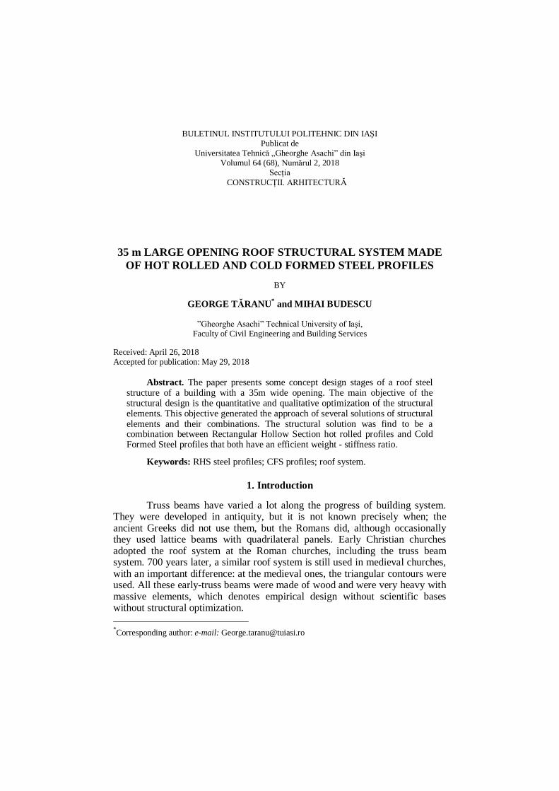
The second generation in the design of truss beams began with the industrial production of steel in the 19th century. Among the first roof structures with truss beams made of steel are Euston Railway Station in London, Fig. 1, built in 1838.
Fig. 1 – Euston Railway Station in London
(http://www.ssplprints.com/image/89253/euston-station-london-1837, 2017).
The shape of these beams was very similar to those of the medieval
buildings except that they were thinner. The unique properties of steel have led to important structural innovations.
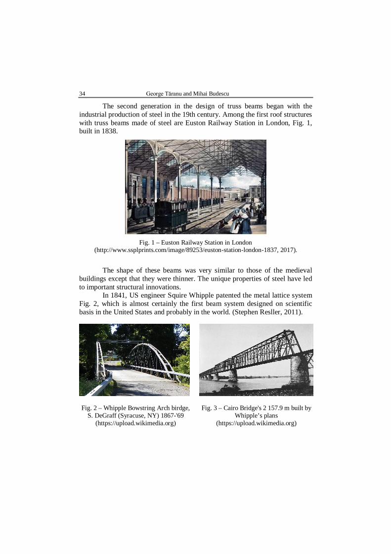
In 1841, US engineer Squire Whipple patented the metal lattice system Fig. 2, which is almost certainly the first beam system designed on scientific basis in the United States and probably in the world. (Stephen Resller, 2011).
Fig. 2 – Whipple Bowstring Arch birdge, S. DeGraff (Syracuse, NY) 1867-'69
(https://upload.wikimedia.org)
Fig. 3 – Cairo Bridge's 2 157.9 m built by Whipple’s plans
(https://upload.wikimedia.org)
Bul. Inst. Polit. Iaşi, Vol. 64 (68), Nr. 2, 2018 35
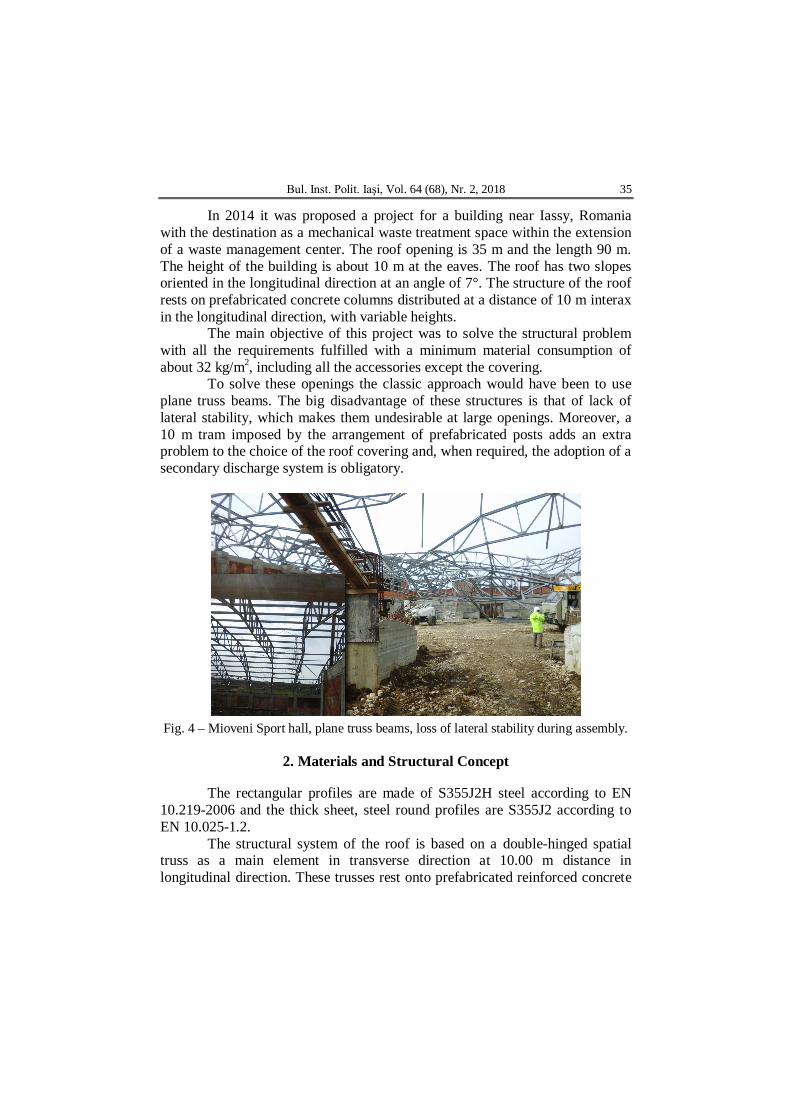
In 2014 it was proposed a project for a building near Iassy, Romania with the destination as a mechanical waste treatment space within the extension of a waste management center. The roof opening is 35 m and the length 90 m. The height of the building is about 10 m at the eaves. The roof has two slopes oriented in the longitudinal direction at an angle of 7°. The structure of the roof rests on prefabricated concrete columns distributed at a distance of 10 m interax in the longitudinal direction, with variable heights.
The main objective of this project was to solve the structural problem with all the requirements fulfilled with a minimum material consumption of about 32 kg/m2, including all the accessories except the covering.
To solve these openings the classic approach would have been to use plane truss beams. The big disadvantage of these structures is that of lack of lateral stability, which makes them undesirable at large openings. Moreover, a 10 m tram imposed by the arrangement of prefabricated posts adds an extra problem to the choice of the roof covering and, when required, the adoption of a secondary discharge system is obligatory.
Fig. 4 – Mioveni Sport hall, plane truss beams, loss of lateral stability during assembly.
2. Materials and Structural Concept The rectangular profiles are made of S355J2H steel according to EN
10.219-2006 and the thick sheet, steel round profiles are S355J2 according to EN 10.025-1.2.
The structural system of the roof is based on a double-hinged spatial truss as a main element in transverse direction at 10.00 m distance in longitudinal direction. These trusses rest onto prefabricated reinforced concrete
36 George Tăranu and Mihai Budescu
columns. In the longitudinal direction, there are plane trusses to stiffen and take over the loads from the secondary beams and transmit to the transverse main trusses. They are located at 8.75 m in the transverse direction. In Fig. 5 an isometric view of the construction is presented.
Fig. 5 – Isometric view of the structural system.
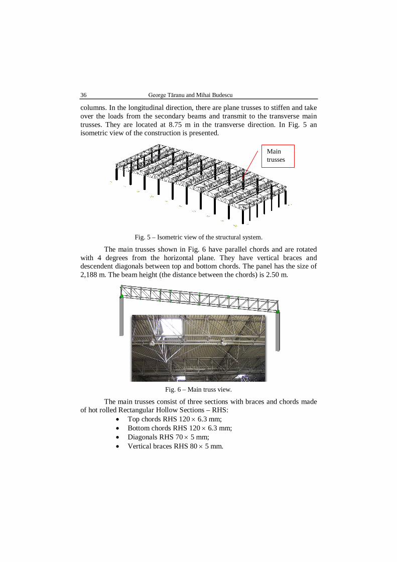
The main trusses shown in Fig. 6 have parallel chords and are rotated with 4 degrees from the horizontal plane. They have vertical braces and descendent diagonals between top and bottom chords. The panel has the size of 2,188 m. The beam height (the distance between the chords) is 2.50 m.
Fig. 6 – Main truss view.
The main trusses consist of three sections with braces and chords made of hot rolled Rectangular Hollow Sections – RHS:
Top chords RHS 120 6.3 mm; Bottom chords RHS 120 6.3 mm; Diagonals RHS 70 5 mm; Vertical braces RHS 80 5 mm.
Main trusses
Bul. Inst. Polit. Iaşi, Vol. 64 (68), Nr. 2, 2018 37
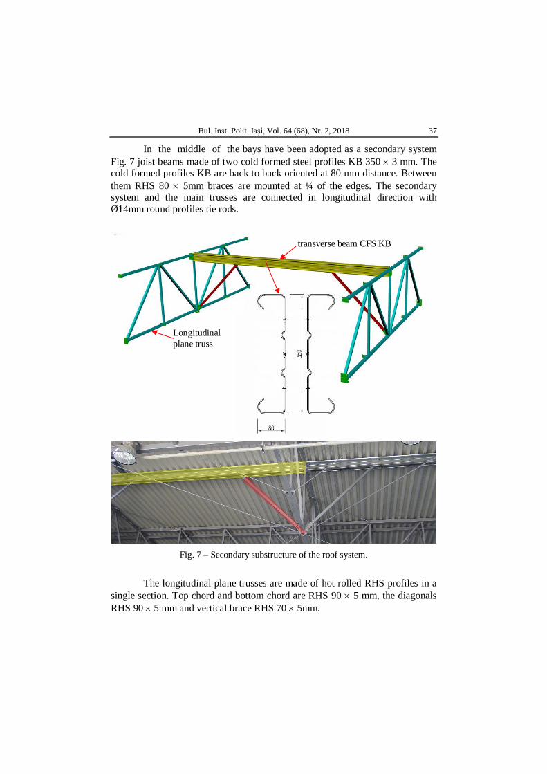
In the middle of the bays have been adopted as a secondary system Fig. 7 joist beams made of two cold formed steel profiles KB 350 3 mm. The cold formed profiles KB are back to back oriented at 80 mm distance. Between them RHS 80 5mm braces are mounted at ¼ of the edges. The secondary system and the main trusses are connected in longitudinal direction with Ø14mm round profiles tie rods.
Fig. 7 – Secondary substructure of the roof system.
The longitudinal plane trusses are made of hot rolled RHS profiles in a
single section. Top chord and bottom chord are RHS 90 5 mm, the diagonals RHS 90 5 mm and vertical brace RHS 70 5mm.
Longitudinal plane truss
transverse beam CFS KB
38 George Tăranu and Mihai Budescu
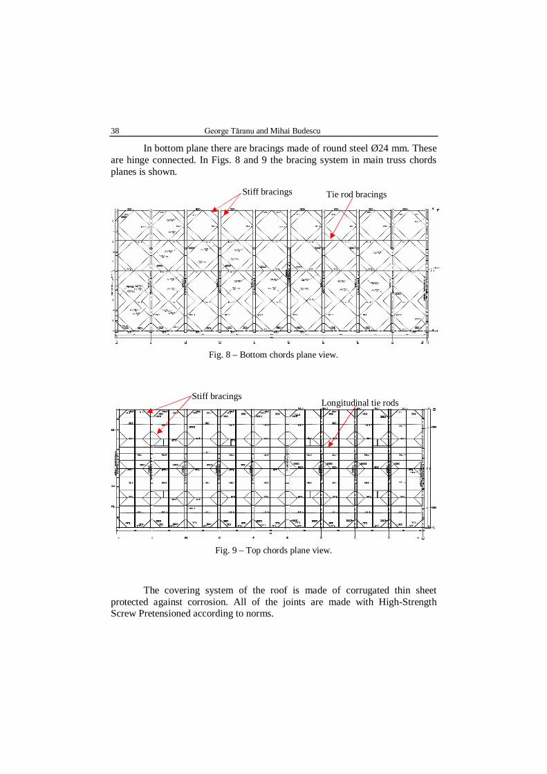
In bottom plane there are bracings made of round steel Ø24 mm. These are hinge connected. In Figs. 8 and 9 the bracing system in main truss chords planes is shown.
Fig. 8 – Bottom chords plane view.
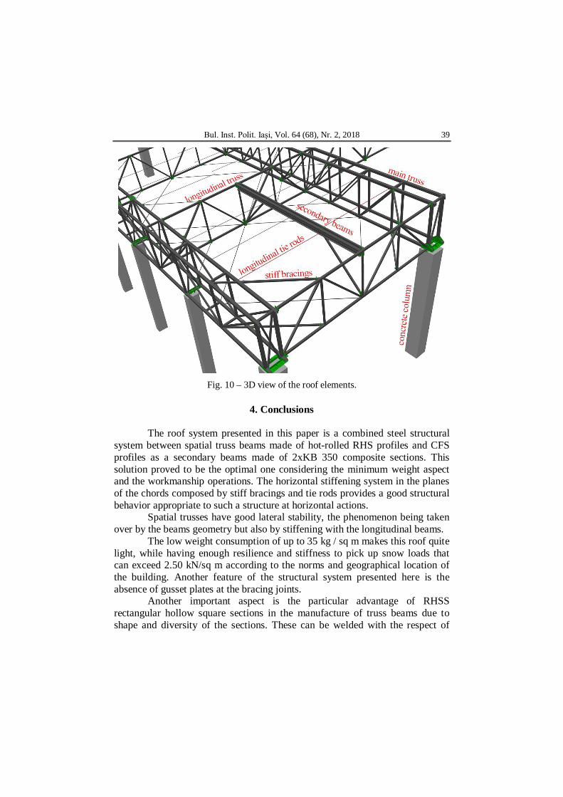
Fig. 9 – Top chords plane view.
The covering system of the roof is made of corrugated thin sheet
protected against corrosion. All of the joints are made with High-Strength Screw Pretensioned according to norms.
Stiff bracings Tie rod bracings
Longitudinal tie rods Stiff bracings
Bul. Inst. Polit. Iaşi, Vol. 64 (68), Nr. 2, 2018 39
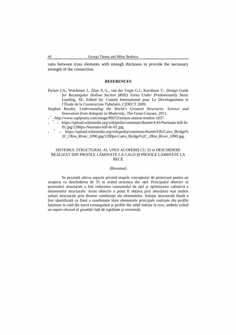
Fig. 10 – 3D view of the roof elements.
4. Conclusions
The roof system presented in this paper is a combined steel structural
system between spatial truss beams made of hot-rolled RHS profiles and CFS profiles as a secondary beams made of 2xKB 350 composite sections. This solution proved to be the optimal one considering the minimum weight aspect and the workmanship operations. The horizontal stiffening system in the planes of the chords composed by stiff bracings and tie rods provides a good structural behavior appropriate to such a structure at horizontal actions.
Spatial trusses have good lateral stability, the phenomenon being taken over by the beams geometry but also by stiffening with the longitudinal beams.
The low weight consumption of up to 35 kg / sq m makes this roof quite light, while having enough resilience and stiffness to pick up snow loads that can exceed 2.50 kN/sq m according to the norms and geographical location of the building. Another feature of the structural system presented here is the absence of gusset plates at the bracing joints.
Another important aspect is the particular advantage of RHSS rectangular hollow square sections in the manufacture of truss beams due to shape and diversity of the sections. These can be welded with the respect of
40 George Tăranu and Mihai Budescu
ratio between truss elements with enough thickness to provide the necessary strength of the connection.
REFERENCES
Packer J.A., Wardenier J., Zhao X.-L., van der Vegte G.J., Kurobane Y., Design Guide
for Rectangular Hollow Section (RHS) Joints Under Predominantly Static Loading, SE, Edited by: Comité International pour Le Développement et l’Étude de la Construction Tubulaire, CIDECT 2009.
Stephen Ressler, Understanding the World’s Greatest Structures: Science and Innovation from Antiquity to Modernity, The Great Courses, 2011.
* * * http://www.ssplprints.com/image/89253/euston-station-london-1837. * * * https://upload.wikimedia.org/wikipedia/commons/thumb/4/45/Normans-kill-br-
01.jpg/1280px-Normans-kill-br-01.jpg. * * * https://upload.wikimedia.org/wikipedia/commons/thumb/f/f6/Cairo_Bridge%
2C_Ohio_River_1890.jpg/1280px-Cairo_Bridge%2C_Ohio_River_1890.jpg.
SISTEMUL STRUCTURAL AL UNUI ACOPERIŞ CU 35 m DESCHIDERE REALIZAT DIN PROFILE LAMINATE LA CALD ŞI PROFILE LAMINATE LA
RECE
(Rezumat)
Se prezintă câteva aspecte privind etapele conceptului de proiectare pentru un acoperiş cu deschiderea de 35 m având structura din oţel. Principalul obiectiv al proiectării structurale a fost reducerea consumului de oţel şi optimizarea calitativă a elementelor structurale. Acest obiectiv a putut fi obţinut prin abordarea mai multor soluţii structurale prin diverse combinaţii ale elementelor. Soluţia structurală finală a fost identificată ca fiind o combinaţie între elementele principale realizate din profile laminate la cald din ţeavă rectangulară şi profile din tablă îndoite la rece, ambele având un raport eficient al greutăţii faţă de rigiditate şi rezistenţă.