3.6 drilling engineering - treccani formation invasion by drilling mud filtrate. • reports on...
TRANSCRIPT

VOLUME I / EXPLORATION, PRODUCTION AND TRANSPORT
3.6.1 General
The planning of a well is a crucial moment in theoil exploration and production process. It is, infact, the basis for making all the importanttechnical choices, for assessing the costs andorganizing the actual construction of the well in themost efficient way.
The well planning starts the moment when theinterpretation of the seismic data and thereconstruction of the geology of the area reveal thepresence of a structure favourable to the accumulationof hydrocarbons. These data also enable an estimate tobe made, both of the depth of the productive levels,and of the stratigraphic and lithological sequences thatwill be encountered during the execution of theborehole as well as of the problems that could emergein an operational phase.
It is at this point that the geologists come into thepicture and draw up a document containing estimatesand proposals for drilling the well on the basis of theinformation in their possession and obtained from: a)geological surface campaigns; b) regional geologicalstudies; c) studies conducted on seismic maps; d)profiles of wells already completed in the area.Obviously these estimates are more accurate whenline or development wells are concerned, and lessaccurate in the case of an exploration (or wildcat)well.
This document is just the prelude to the drawing upof the proper drilling programme which, to be reallyeffective, must take into consideration all of theavailable data. In fact, it has to give the data necessaryfor the well location, indicating the drilling objectiveor objectives, the foreseen final depth, forecasts as tothe litho-stratigraphic profile, the need to makeelectric logs and/or taking cores. It must alsoanticipate the most likely drilling problems that could
be encountered, and indicate any earlier boreholes tobe referred to so as to obtain further information andmore substantial data.
By consulting the final reports and thedocumentation regarding the reference wells, thedrilling expert, who supervises the planning of thewell, assisted by the geologist and the geophysicist, isable to obtain all the information enabling reliable welldesign to be achieved. The documents that are usuallyavailable are:• Geological profiles – called 1:1,000 profiles in oil
jargon – from which a vast amount of, above all,qualitative information may be gleaned, such as: thelithological well profile obtained by analysing thebit cuttings and the logs (in particular thoseregarding resistivity and spontaneous, or self,potential); hydrocarbon occurrences, the nature andamount thereof; casing depth, diameter of strings,quantity of cement used and data on cement risingin the hole-casing clearance; drilling fluid density;mud absorption by the formations with indicateddischarges and depths at which the phenomenon hasoccurred; verticality tests carried out and relativeresults; list of logs recorded with indication of typeand intervals concerned; number of cores taken,recovery percentage, their lithological description,formation dips and hydrocarbons occurrences;results of analyses conducted on samples taken;strata tests and results; data of any production tests;types of mineralization (oil, gas, water); final stateof well (productive, dry).
• Logs, the interpretation of which makes it possibleto obtain, besides some of the data alreadyindicated above (e.g. lithological), additionalinformation of basic importance such as: forecastsof the trend of the geostatic stress and of the poreand fracture pressure; permeability and porosityvalues of the formations to be drilled; values of
403
3.6
Drilling engineering
formation invasion by drilling mud filtrate.• Reports on strata tests enabling the trend of the
pressure gradients obtained through loginterpretation to be verified.
• Drilling reports, providing information on: bitperformance; hydraulic parameters; casing stringdesign; causes and remedies of any drillingaccidents that have occurred; absorption of drillingmud and methods applied to remedy this; analysisof drilling times; drilling costs.
• Reports on drilling fluid, showing: types of fluidused and their characteristics; any contaminationsencountered and measures adopted to counterthem; absorption losses and relevant measures;rheological data and hydraulic parameters; costs ofdrilling fluid and additives.
• Reports on cementing from which data areobtained on: type and quantity of cement used foreach single operation; additives used and reasonfor their use; casing equipment used; time ofrunnning in the casing; snags encountered inrunning-in of the casing; cementing logs used(e.g. thermometric, sonic) indicating the rise of thecement slurry and quality of cementing.
• Reports on cement plugs and on any secondarycementing carried out to meet well problems or forcomplete shut-off of well, with indication of:amount of absorptions; reason for the plugs anddata on execution and quantity of cement used;assessment of success of operations.The analysis and processing of all this large mass
of information provides the drilling technician with theessential elements for drawing up the drillingprogramme.
3.6.2 Drawing up of drillingprogramme
So far it has been seen what information has to beobtained and what documents have to be consultedby the technician to be able to arrive at a reliabledrilling programme. Before describing how such aprogramme must be prepared it should be recalledthat every well has its own peculiar features; in fact,its depth can vary from a few hundred metres to sixor seven thousand metres and even more, it may beexploratory, for field development or delimiting,onshore or offshore, vertical, directional orhorizontal (the various aspects regarding these lasttwo categories of wells are dealt with in detail inChapter 3.2, but the basic criteria are the same for allwell types).
Having outlined these premises, the first step tobe taken by the technician to work out the drilling
programme is to construct, alongside thestratigraphic and the lithological profiles indicatedby the geophysicists and the geologists, the trend ofthe pressure gradient curves according to depth, i.e.the geostatic, pore pressure and fracture gradients,which will enable him to design the well casingprofile, which is an essential condition for beingable to achieve the foreseen mining objective orobjectives.
Forecasting and calculation of pressure gradientsFor the correct design of a well, as already
observed, the initial phase of forecasting andcalculation of the pressure gradients is of basicimportance, because knowledge thereof is thestarting point of the whole process of well planning;the greater the precision and reliability of theforecasts of their trends, the easier the design willbe, the closer the real well will match theprogrammed one, and the fewer the modificationsand adjustments that will have to be made during theexecution of the project.
Knowledge of the pressure gradients, in fact, canprovide, in sequence, all the information necessary andindispensable for setting up the executive well drillingand production programmes in a logical manner, as thefollowing can be more correctly defined:• The optimal levels of well casing.• The number and diameter of the casings to be used.• The grade and thickness of the steel for the pipes
in order to withstand the stresses to which thestrings will be subjected both during actual drillingand during the productive life of the well.
• The optimal density and rheological characteristicsof the drilling mud and of the cement slurries.
• The drawing up and optimizing of the hydraulicprogramme (choice of pumps and surfaceequipment).
• Choice and optimizing of bits.• Definition of the mechanical characteristics of the
drill string and of its stabilization.• Choice of wellhead.• The capacity of the drilling rig, which is linked to
the geometry (length and diameter) and weight ofthe casing to be lowered.
• Choice of safety equipment, such as BOP(BlowOut Preventers), choke manifolds, surfaceequipment in general.
• Installation of the most suitable equipment andsensors for the continuous and real-timemonitoring of the parameters that serve to keep thevarious operational phases under control (mudlogging units).
• Well cost estimate with the relevant budgetallocation.
404 ENCYCLOPAEDIA OF HYDROCARBONS
DRILLING AND COMPLETION OF WELLS

Subsoil tensions, pore pressure, fracture pressureA rock consists of solid elements and of empty
spaces (pores), which may be filled with liquids and/orgases. Rock lying at a certain depth is acted upon bythe weight of the overlying sediments, which inducetensions defined as geostatic or lithostatic stresses,which in their turn produce on this rock a state oftension that influences its mechanical behaviour andwhich, therefore, have to be determined. Also thefluids contained in the rock pores exert pressures,called pore or formation pressures, which it isnecessary to know and to overcome in the drillingphase. Geostatic stresses and stratum pressures areclosely correlated with each other and determine thevalue assumed by the fracture pressure pfr, that is thepressure which, applied inside the hole, causes thefracturing of the rock, giving rise to severe wellproblems. These functions are analysed below,indicating what influence they may have on theconstruction of an oil well.
At a generic depth H, the total vertical load sov(usually known as overburden pressure, assumed to bepositive if in compression), which in the absence oftectonic forces is the maximum load, is given by therelation:
sov�rt gH
with rt as the average soil density, from the surface tothe depth H, which takes into account both the solidmatrix and the fluids contained in it (generallyrt�2.2-2.3 g�cm3) and g the acceleration of gravity;or, in terms of the density as a function of the depth,
H
sov��rt (z)gdz 0
where z is the vertical coordinate, or even, in the caseof n strata of different density and thickness,
n
sov�� ri gHii�0
to which corresponds the average geostatic gradient(overburden gradient)
n
� ri gHii�0
Gov� 111n
� Hii�0
while the effective vertical load, sov,eff, on whichdeformation and fracture depend, is
sov,eff�sov�pp
where pp is the pore pressure.When a stratum, at depth H, is in communication
with the surface, in the case of the subsoil being
completely saturated with water, this pressure is thatproduced by a water column of height H. In this case,the stratum pressure is called normal and is given by
pp�rw gH
and the corresponding gradient
Gp�rwg
where rw is the density of the water saturating the soil,varying between 1 and 1.07 g�cm3; normally it isassumed that rw�1.03 g� cm3. In the case of strataisolated from the surface, this pressure can assumedifferent values and is called anomalous pressure.
The effective horizontal load, soh,eff, determined byensuring that horizontal expansion is prevented, isinstead
soh,eff � [n/(1�n)]sov,eff
where n is the Poisson ratio with average values of 0.25for rocks which have an elastic behaviour (e.g. sands,sandstones, limestones) and of 0.50 for rocks whichhave a totally plastic behaviour (e.g. clays).
It follows that in borderline cases, the effectivehorizontal load is equal to one-third of the effectivevertical load for elastic rocks (limestone, dolomite),while it equals it in the case of plastic rocks (pure clay).
The presence of the well modifies the state of thestresses in the surrounding area and the mud, generallyexerting a hydraulic pressure greater than that of thefluids contained in the rock pores, can give rise totensile stresses in the subsoil and even createconditions that can cause the fracture of the rock in adirection normal to that of least resistance (usuallyhorizontal) with consequent mud absorption or evenloss of circulation. Because of this, fracturing is morelikely to occur in elastic soils than in plastic ones.Knowledge of the trend of the fracture pressure as afunction of depth is, therefore, of fundamentalimportance for programming drilling, as it providesthe technician with the information necessary forestablishing the depth to which the casing should belowered, the optimal density of the drilling fluid to beused and the maximum pressure values that must notbe exceeded at the wellhead in the event of treatmentand control of a kick.
Without going into detail, the fracture pressure andgradient can be calculated with very simple formulae,once the average geostatic gradient Gov and porepressure gradient Gp are known. If the mud does notpenetrate into the formation, in formations having anelastic behaviour, the fracture gradient, Gfr, whichexpresses the variation of fracture pressure with depth,is given by
Gfr � Gp�(2v/1�v)(Gov�Gp)
405VOLUME I / EXPLORATION, PRODUCTION AND TRANSPORT
DRILLING ENGINEERING

In formations having a plastic behaviour on theother hand, such as clays or marls, the case is thefollowing:
Gfr�Gov
Notions on the origins of overpressuresFormations with abnormal pressure are frequently
encountered all over the world both in recent soils,even Pleistocene, and in ancient soils, even Cambrian.Because of the consequences they have on operationsand on the safety of people and plant, overpressureshave certainly deserved, and still deserve, particularattention, which however is not reserved for situations– moreover less frequent in nature – characterized bypressures lower than the hydrostatic pressure.
A geological environment of normal pressure maybe depicted as a hydraulically ‘open’ system, such asmay be constituted by permeable formations that allowhydrostatic conditions to be established. On thecontrary, systems with abnormally high pressures maybe termed ‘closed’ systems, as they prevent – or atleast greatly reduce – the passage of fluids from one tothe other. Formations with normal and anomalouspressure coexist only if separated by a barrier ofpermeability, which also acts simultaneously as apressure barrier. In theory, such a barrier can beprovided by any rock or combination of rocks presentin the Earth’s crust, which reduces or prevents themovement and the passage of considerable volumes offluids. The lithology that most commonly acts as apermeability barrier is represented by clayeyformations. This type of material, in fact, due to amultiple series of factors of a geological, physical,chemical and mechanical nature, can in the course ofgeological ages undergo diagenetic variations makingit particularly impervious to the movement of thefluids contained in it.
Among the most common causes that can give riseto the formation of overpressures, are the following: a)phenomena linked with the velocity of sedimentation;b) diagenetic processes (diagenesis of clays, ofsulphates, secondary precipitation of cementingmaterials, organic decomposition); c) osmoticphenomena; d) tectonics; e) artesian pressures.
Of these various phenomena, certainly those linkedwith the rate at which sediments are deposited are themost frequent cause of the occurrence of overpressureconditions. During the sedimentation phase, in fact,the materials that accumulate in a sedimentary basinare subject to compaction processes through the effectof the materials successively deposited on them.Gradual compaction, with each subsequent increase inload, generates a hydraulic imbalance at the beginningdue to the low compressibility of the water contained
in the pores, so that in order to re-establish a balancedpressure, this is slowly expelled through the pores ofthe sediments. This means that under normalconditions the porosity of the sediments tends todiminish progressively with increased depth. If,however, the geological parameters that influencedeposition and, moreover, if the characteristics of therock are such as not to permit the normal discharge ofthe quantity of water in excess in the pores, as occursin the case of the deposition of clayey material (i.e. ifthe rate at which the sediments accumulate on eachother is greater than the rate at which the water isexpelled from the pores of the rock), the pressure ofthe fluid contained in the pores will be greater than thehydrostatic value and, therefore, the porosity of therock will be greater than the value that would beexpected for that given depth, as the sediments aresubjected to smaller effective tensions than those thatthey would have supported in the presence of normalpressures (that is, they are under-consolidated) andconsequently have different mechanical and physicalcharacteristics from those of the same soils normallyconsolidated. Furthermore, in the case of clays, thesetend to expand in the hole, if this phenomenon is notcounteracted by sufficient pressure of the mud.
Overpressures can also be due to diagenesis, that isby the post-depositional process of alteration ofsediments and of the minerals forming them.Diagenetic processes include the formation of newminerals, the redistribution and recrystallization ofsubstances present in the sediments, and lithification,and their final effect is an increase in the pressure ofthe fluids contained in the pores of the rock withrespect to the original deposition conditions.
Lastly, it should be observed that overpressuresmay be present in both permeable formations and inthose of extremely low permeability, such as clays.Although in this last case no appreciable entry of fluidinto the well occurs in practical working conditions,nevertheless identifying the overpressure levels is ofvery great importance as it signals, in good time, thepossible occurrence of overpressures in underlyingstrata of high permeability, which, if notcounterbalanced with adequate mud pressure, couldgive rise to serious well problems. Being able toestablish whether the clays drilled have an anomalouspressure makes it possible, in fact, to avoid the drillstring getting stuck, any forcing in the operationalphase, sloughing-in of hole wells and increases intorsional moment of the drill string (these are allphenomena caused by borehole restriction in clayeyformations), and kick contained in porous andpermeable formations underlying the clays inoverpressure, which could even lead to uncontrolledblowouts.
406 ENCYCLOPAEDIA OF HYDROCARBONS
DRILLING AND COMPLETION OF WELLS
Methods of calculating pressure gradientsAs already recalled, a correct, reliable estimate of
the pressure gradients that will be encountered indrilling a well represents a moment of fundamentalimportance for an effective planning of operations andfor their subsequent management in the executivephase.
Pore, sediment and fracture pressures can bedetermined using various techniques and methods,each of them applicable during the various phases ofthe operative process, i.e:• Before starting on well drilling, essentially for
design purposes, the techniques are based onanalysis of seismic data and on processing datarelating to reference wells already constructed inthe area or having similar characteristics, such asdrilling logs and parameters.
• During drilling, these techniques are based onmonitoring and processing of the drillingparameters with reference to the well in question.
• After drilling each section of the well, the methodsused based on log recording and processing.
Calculation of geostatic gradientThe method most commonly used is based on the
analysis of seismic data, after having transformed theinterval rates (i.e. the physical rates of propagation ofthe seismic signals within strata delimited by tworeflectors) derived from processing the seismic lines ininterval transit times. There exists, in fact, a well-defined relation, obtained from field experiments,between the density of the rock, rb (which includesboth the rock matrix and the fluids contained in it), theinterval transit times, i.e. the time taken by the elasticwave to traverse a given rocky medium, Dtint, theinterval rates, i.e. the rate of propagation of the elasticwave, Vint, which is, obviously, inversely proportionalto the times, and the depth of the formation underexamination.
The procedure consists in calculating the values ofrb with special relations, starting with the readings ofVint or Dtint, at all the intervals into which the well canbe subdivided and then integrating them as a functionof the depth and converting them into thecorresponding geostatic pressure and gradient values,pov and Gov. The values of Gov are then entered in adiagram as a function of the depth, obtaining a curvethat reflects the particular lithology of the well beingexamined and the conditions under which thesedimentation of the soils occurred (Fig. 1).
Other methods exist which enable the trend of thegeostatic gradient to be reconstructed, based onprocessing both the logs (in particular the sonic log)and the drilling parameters, by means of a far morecomplex procedure.
Calculation of the pore pressure gradientCalculation of the pore pressure gradient is the
most critical aspect of the process of reconstructingthe trend of the pressure gradients. For this reason, inthe course of time, various methods have beendeveloped which have made its determination moreand more reliable in the various operative phases, thatis in the drilling phase, before starting the well (usingseismic data) and after having drilled a section of thehole (by processing the logs).
Initially, around the Sixties and the Seventies,reference was made to basically qualitative techniques(which gave only indications on the nearness orotherwise of an anomalous situation, without enablingit to be quantified). Then, in the ensuing years, moresophisticated methods were developed, also enabling aquantitative determination to be made of the porepressure gradient. For this reason, towards the mid-Seventies, drilling rigs started to be equipped with even very complex instruments and monitoringand data processing systems, which made it possible,and still make it possible now, to record numerousparameters and to process them in real time, ensuringcontinuous control and optimization of operations. Ofthe information commonly recorded, measured andprocessed for pressure control purposes, the followingshould be mentioned: a) drilling bit parameters, suchas weight, rotations per minute (rpm), torsion, forcing,rate of penetration; b) mud circulation flow rate andhead losses; c) mud density entering and leaving well;
407VOLUME I / EXPLORATION, PRODUCTION AND TRANSPORT
DRILLING ENGINEERING
50 1.7
6,0006,000
5,000
4,000
3,000
2,000
1,000
0PC
5,000
4,000
3,000
2,000
1,000
02.0 2.5100 200
ns/ft
a c b
dept
h (m
)
bar/10 m g/cm3
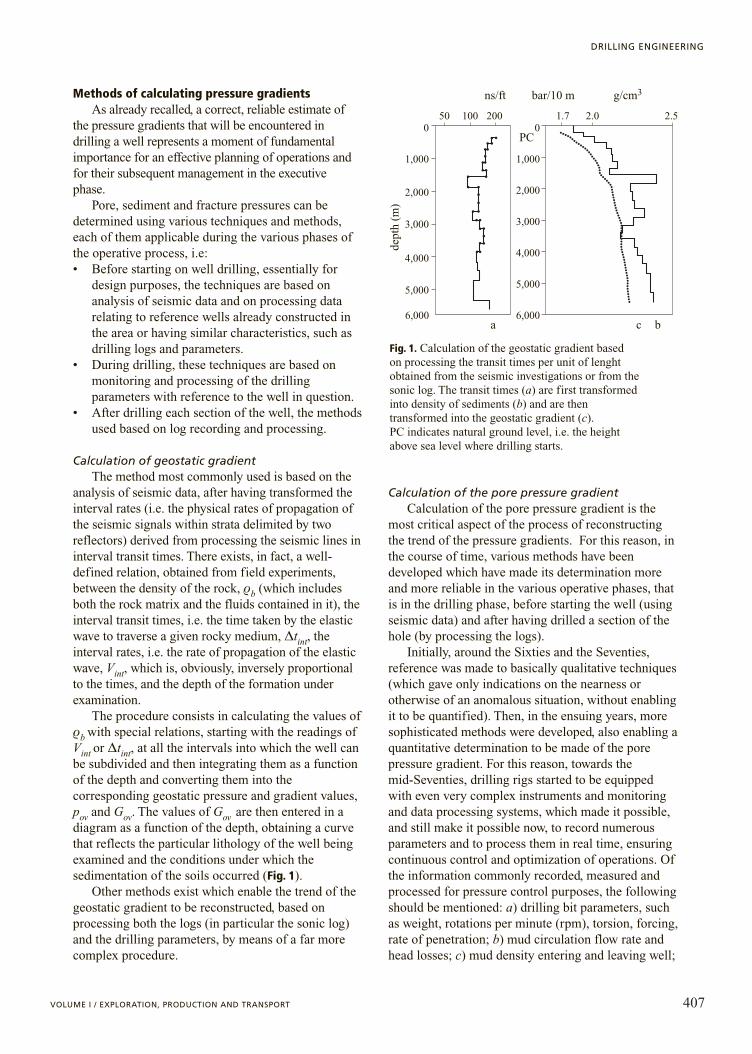
Fig. 1. Calculation of the geostatic gradient based on processing the transit times per unit of lenght obtained from the seismic investigations or from the sonic log. The transit times (a) are first transformed into density of sediments (b) and are then transformed into the geostatic gradient (c). PC indicates natural ground level, i.e. the height above sea level where drilling starts.
d) mud temperature entering and leaving well; e)concentration of chlorides and resistivity of drillingmud; f ) density and montmorillonite content of claysbrought to surface by circulating muds; g) presence ofgas in mud during drilling and trips; h) informationobtained by processing drilling parameters applyingdc-exp (corrected drilling exponent) and sigmalogmethods, described below.
As already observed, the majority of thesequantities provide a qualitative assessment of the porepressure gradient, while only the last two methodsmentioned (dc-exp and sigmalog) and analogousmethods enable a quantitative assessment to be made.
The reason why the majority of this information isconsidered capable of indicating the presence of ananomalous situation is that when, during drilling, aformation with overpressure is entered withoutchanging the density of the mud in the well, there areeven significant variations in some drillingparameters. For example, under normal conditions,that is, when the pore pressure gradient remains athydrostatic values, the rate of penetration of the bittends to diminish with depth, as the differentialpressure, i.e. the difference between the pressureexerted by the mud column in the well and thepressure of the fluids contained in the rock pores,increases in consequence. The progressive increase inthe differential pressure with depth causes the cuttingsremoved by the bit from the bottom of the hole toremain for a longer time at the bottom before beingbrought to the surface; moreover, the compactingprocess, to which the rocks have been subjected duringsedimentation, if this has taken place normally,determines an increase in the hardness of the rock and,for the same lithotype, makes drilling more difficult.When an area is entered in which the pore pressuregradient tends to increase and to differ from thenormal trend due to anomalous compaction, thedifferential pressure, if the mud density is keptconstant, diminishes and consequently there is anincrease in the penetration rate, for the same lithotype.As, however, the lithotype varies with considerablefrequency in a well, this explains why the penetrationrate alone is unable to provide reliable indications onthe pore pressure gradient.
To have an idea about how a certain parametervaries with depth due to the abnormal development ofthe pore pressure gradient, it is necessary to eliminatethe variables that in some way might mask thephenomenon. One of the first things to be done is thusto refer to a standard lithotype. This lithotype isrepresented, as seen, by the clay formations, for aseries of reasons. First and foremost, clays, beingimpermeable or having an extremely low permeability,are the main cause of the formation of areas of
overpressure, as they do not always enable a balance tobe reached between the rate at which they aredeposited and the rate at which they allow the watercontained in their pores to be eliminated. In the secondplace, again due to their low permeability, they can bedrilled even with muds having a lower density withrespect to the effective pore pressure gradient withoutcausing serious well problems, thereby leavingsufficient time for the appropriate countermeasures tobe taken. Lastly, clays are an effective permeabilitybarrier and act as cover for permeable strata, in theirturn in overpressure, which, if penetrated underunbalanced conditions, could even lead to a blowout.For these reasons, all the techniques enabling thedevelopment of formation pressures to be foreseen andquantified, have been developed and are applied inclay formations, which, therefore, must beappropriately identified.
As the penetration rate, other parameters, too, varyappreciably when in the presence of overpressurizedformations. For example, the density of clays, undernormal compaction conditions, increases with depthbecause their porosity and therefore their fluid contentdiminish. In areas of overpressurized pressure, whereporosity and fluid content are greater than expected, thedensity of the clay on the contrary diminishes. Byshowing in the diagram the density of the clay as afunction of depth, until it is observed that this quantitytends to increase with depth, it can be inferred that thepore pressure gradient is maintained under normalconditions, while when it diminishes it means thatoverpressurized formations are present. Likewise, thecontent of chlorides in the mud can increase and itsresistivity can diminish, as a certain quantity of saltwater enters the well from the formation; or theconcentration of dissolved gas in the mud couldincrease, for the same reasons as those mentioned above.
Also certain typical drilling problems (e.g.overpull, increases in torsional moment, etc.) increasetheir incidence on operations in the event ofoverlapping, because the borehole walls, notadequately supported by the pressure exerted by themud, tend to become more and more unstable and tonarrow progressively, even to the point of collapse,unless remedial action is taken promptly by restoringan adequate differential pressure.
The penetration rate generally tends to diminishwith depth if the formations have a normal gradient or,if there is overpressure, if the difference between themud density value in the hole and the pore pressuregradient is kept constant, that is to say if thedifferential pressure increases regularly with the depthof the hole. As, however, the penetration rate varies notonly according to the lithology being drilled, but alsoas a function of the drilling parameters adopted, it is
408 ENCYCLOPAEDIA OF HYDROCARBONS
DRILLING AND COMPLETION OF WELLS
clear that it is subject to variations that do not enablethe presence of formations having an anomalousbehaviour to be definitely identified. To allow for thisand to eliminate those factors that could mask themeeting of overpressure levels, rather complexdrillability equations have been developed, whichcorrect and normalize the penetration rate, as afunction of the lithostratigraphic and operativevariations that have occurred.
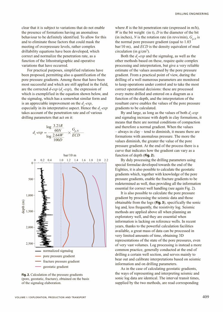
For practical purposes, simplified relations havebeen proposed, permitting also a quantification of thepore pressure gradients. Among those that have beenmost successful and which are still applied in the field,are the corrected d-exp (dc-exp), the expression ofwhich is exemplified in the equation shown below, andthe sigmalog, which has a somewhat similar form andis an appreciable improvement on the dc-exp,especially in its interpretative aspect. Hence the dc-exptakes account of the penetration rate and of variousdrilling parameters that act on it:
3.21Rlog121260N Gp,Ndc-exp �11111�1212
2.64W ECDlog1212100D
where R is the hit penetration rate (expressed in m/h),W is the bit weight (in t), D is the diameter of the bit(in inches), N is the rotation rate (in revs/min), Gp,N isthe normal pore pressure gradient (equal to 1.03bar/10 m), and ECD is the density equivalent of mudcirculation (in g/cm3).
Both the dc-exp and the sigmalog, as well as theother methods based on these, require quite complexprocessing and interpretation, but give a very reliableestimate of the values assumed by the pore pressuregradient. From a practical point of view, during thedrilling of a well numerous parameters are monitoredto keep operations under control and to take the mostcorrect operational decisions: these are processedevery metre drilled and entered on a diagram as afunction of the depth, and the interpretation of theresultant curve enables the values of the pore pressuregradients to be calculated.
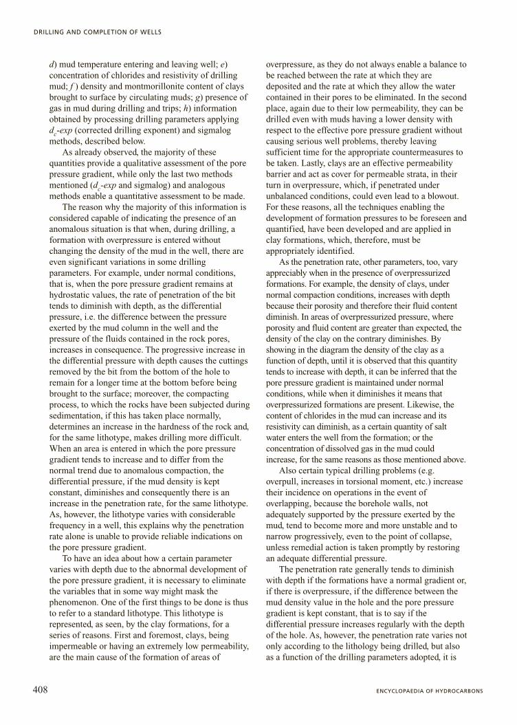
By and large, as long as the values of both dc-expand sigmalog increase with depth in clay formations, itmeans that there are normal conditions of compactionand therefore a normal gradient. When the values – always in clay – tend to diminish, it means there areformations with anomalous pressure. The more thevalues diminish, the greater the value of the porepressure gradient. At the end of the process there is acurve that indicates how the gradient can vary as afunction of depth (Fig. 2).
By duly processing the drilling parameters usingspecial formulae developed towards the end of theEighties, it is also possible to calculate the geostaticgradients which, together with knowledge of the porepressure gradients, enable the fracture gradients to beredetermined as well, thus providing all the informationessential for correct well handling (see again Fig. 2).
It is also possible to calculate the pore pressuregradient by processing the seismic data and thoseobtainable from the logs (Fig. 3), specifically the soniclog and, less frequently, the resistivity log. Seismicmethods are applied above all when planning anexploratory well, and they are essential wheninformation is lacking on reference wells. In recentyears, thanks to the powerful calculation facilitiesavailable, a great mass of data can be processed invery limited amounts of time, obtaining 3Drepresentations of the state of the pore pressures, evenof very vast volumes. Log processing is instead a morecommon practice, generally conducted at the end ofdrilling a certain well section, and serves mainly tobear out and calibrate interpretations based on seismicinformation and on drilling parameters.
As in the case of calculating geostatic gradients,the ways of representing and interpreting seismic andsonic log data are identical. The interval transit times,supplied by the two methods, are read corresponding
409VOLUME I / EXPLORATION, PRODUCTION AND TRANSPORT
DRILLING ENGINEERING
2,500
2,000
1,500
1,000
500
00 0.2 0.4 1.0 1.2
bar/10 m1.4 1.6 1.8 2.0 2.2
dept
h (m
)
normalized sigmalog
pore pressure gradient
fracture pressure gradient
geostatic gradient
Fig. 2. Calculation of the pressure gradients (pore, geostatic, fracture), obtained on the basis of the sigmalog elaboration.
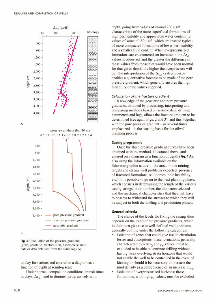
to clay formations and entered in a diagram as afunction of depth at semilog scale.
Under normal compaction conditions, transit timesin clays, Dtsh, tend to diminish progressively with
depth, going from values of around 200 ms/ft,characteristic of the more superficial formations ofhigh permeability and appreciable water content, tovalues of some 60-80 ms/ft, which are instead typicalof more compacted formations of lower permeabilityand a smaller fluid content. When overpressurizedformations are encountered, an increase in the Dtshvalues is observed, and the greater the difference ofthese values from those that would have been normalfor that given depth, the higher the overpressure willbe. The interpretation of the Dtsh vs depth curveenables a quantitative forecast to be made of the porepressure gradient, which generally ensures the highreliability of the values supplied.
Calculation of the fracture gradientKnowledge of the geostatic and pore pressure
gradients, obtained by processing, interpreting andcomparing methods based on seismic data, drillingparameters and logs, allows the fracture gradient to bedetermined (see again Figs. 2 and 3); and this, togetherwith the pore pressure gradient – as several timesemphasized – is the starting basis for the oilwellplanning process.
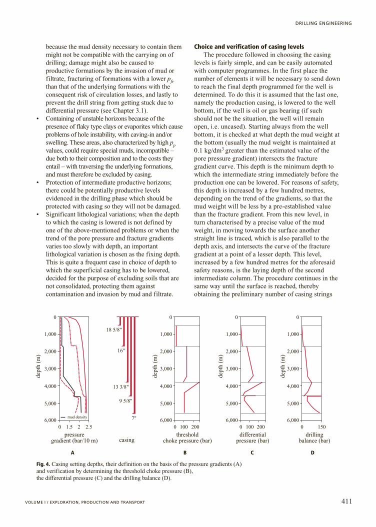
Casing programmeOnce the three pressure gradient curves have been
obtained with the methods illustrated above, andentered on a diagram as a function of depth (Fig. 4 A),also using the information available on thelithostratigraphic nature of the area, on the miningtargets and on any well problems expected (presenceof fractured formations, salt domes, hole instability,etc.), it is possible to go on to the next planning phase,which consists in determining the length of the variouscasing strings, their number, the diameters selectedand the mechanical characteristics that they will haveto possess to withstand the stresses to which they willbe subject in both the drilling and production phases.
General criteriaThe choice of the levels for fixing the casing shoe
depends on the trend of the pressure gradients, whichin their turn give rise to well-defined well problemsgenerally coming under the following categories:• Isolation of zones that could give rise to circulation
losses and absorptions; these formations, generallycharacterized by low pp and pfr values, must beexcluded to be able to continue drilling withouthaving weak overlying strata horizons that wouldnot enable the well to be controlled in the event ofkicking or should it be necessary to increase themud density as a consequence of an increase in pp.
• Isolation of overpressurized horizons; theseformations, with high pp values, must be excluded
410 ENCYCLOPAEDIA OF HYDROCARBONS
DRILLING AND COMPLETION OF WELLS
A
B
0.6
400
800
1,200
1,600
2,000
2,400
2,800
3,200
3,600
4,000
4,400
0.8 1.0 1.2 1.4 1.6 1.8 2.0 2.2 2.4
lithology
pressure gradient (bar/10 m)
400
0100 200
800
1,200
1,600
2,000
2,400
2,800
3,200
3,600
4,000
4,400
Dtsh (ms/ft)de
pth
(m)
dept
h (m
)
pore pressure gradient
fracture pressure gradient
geostatic gradient
60
Fig. 3. Calculation of the pressure gradients (pore, geostatic, fracture) (B), based on seismic data or data obtained from the sonic log (A).
B
A
because the mud density necessary to contain themmight not be compatible with the carrying on ofdrilling; damage might also be caused toproductive formations by the invasion of mud orfiltrate, fracturing of formations with a lower pfrthan that of the underlying formations with theconsequent risk of circulation losses, and lastly toprevent the drill string from getting stuck due todifferential pressure (see Chapter 3.1).
• Containing of unstable horizons because of thepresence of flaky type clays or evaporites which causeproblems of hole instability, with caving-in and/orswelling. These areas, also characterized by high ppvalues, could require special muds, incompatible –due both to their composition and to the costs theyentail – with traversing the underlying formations,and must therefore be excluded by casing.
• Protection of intermediate productive horizons;there could be potentially productive levelsevidenced in the drilling phase which should beprotected with casing so they will not be damaged.
• Significant lithological variations; when the depthto which the casing is lowered is not defined byone of the above-mentioned problems or when thetrend of the pore pressure and fracture gradientsvaries too slowly with depth, an importantlithological variation is chosen as the fixing depth.This is quite a frequent case in choice of depth towhich the superficial casing has to be lowered,decided for the purpose of excluding soils that arenot consolidated, protecting them againstcontamination and invasion by mud and filtrate.
Choice and verification of casing levelsThe procedure followed in choosing the casing
levels is fairly simple, and can be easily automatedwith computer programmes. In the first place thenumber of elements it will be necessary to send downto reach the final depth programmed for the well isdetermined. To do this it is assumed that the last one,namely the production casing, is lowered to the wellbottom, if the well is oil or gas bearing (if suchshould not be the situation, the well will remainopen, i.e. uncased). Starting always from the wellbottom, it is checked at what depth the mud weight atthe bottom (usually the mud weight is maintained at0.1 kg�dm3 greater than the estimated value of thepore pressure gradient) intersects the fracturegradient curve. This depth is the minimum depth towhich the intermediate string immediately before theproduction one can be lowered. For reasons of safety,this depth is increased by a few hundred metres,depending on the trend of the gradients, so that themud weight will be less by a pre-established valuethan the fracture gradient. From this new level, inturn characterised by a precise value of the mudweight, in moving towards the surface anotherstraight line is traced, which is also parallel to thedepth axis, and intersects the curve of the fracturegradient at a point of a lesser depth. This level,increased by a few hundred metres for the aforesaidsafety reasons, is the laying depth of the secondintermediate column. The procedure continues in thesame way until the surface is reached, therebyobtaining the preliminary number of casing strings
411VOLUME I / EXPLORATION, PRODUCTION AND TRANSPORT
DRILLING ENGINEERING
A B C D
mud density6,000
5,000
4,000
3,000
2,000
1,000
0
6,0000 2.521.5 0 200100
5,000
4,000
3,000
2,000
1,000
dept
h (m
)
dept
h (m
)
dept
h (m
)
dept
h (m
)
18 5/8"
16"
13 3/8"
9 5/8"
6,000
5,000
4,000
3,000
2,000
1,000
0
0 200100
pressuregradient (bar/10 m)
thresholdchoke pressure (bar)
differentialpressure (bar)
drillingbalance (bar)casing
6,000
5,000
4,000
3,000
2,000
1,000
0
0 150
7"
0
Fig. 4. Casing setting depths, their definition on the basis of the pressure gradients (A) and verification by determining the threshold choke pressure (B), the differential pressure (C) and the drilling balance (D).
A B C D
required in this well, to which a conductor casingelement and an anchor string will normally be added.
The number of strings usually required to constructa well can vary between 4 and 7, according to itsdepth, the trend of the pressure gradients and themining targets to be reached. The definition of thenumber of strings determines, in its turn, theirdiameter.
As already emphasized in Chapter 3.1, the stringscarry out very important and diversified functionsaccording to the depth to which they are lowered. Thefirst string to be used is the conductor pipe, in actualfact a string of large-diameter pipes (from 42'' to 30''),chamfered at their ends to allow them to be welded.After the conductor pipe comes the anchor string,which has to bear the weight of the successivecolumns (called intermediate columns), because at thetop of it is welded the base flange, to which afterwardsall the other columns will be anchored. Theintermediate columns are lowered between the surfacestring and the final production string, if the wellproves to be oil bearing. They are normally the mosthighly stressed columns, in which the wear and tearwill be more evident because of the long time in whichthe drill string will rotate in them. The final orproduction string is, lastly, the column on which theproductive life of the well depends. Therefore it has tobe planned and installed as accurately as possible, soas to eliminate all possible snags, paying particularattention to its equipment which has to be optimizedabove all at the oil-bearing levels. In place of entireintermediate and production strings, liners aresometimes used, these beings columns not reaching allthe way to the surface, but which are placed using drillpipes some tens of metres inside the shoe of thepreceding column. The use of liners is common indeep wells as they enable head losses to be reduced,thereby limiting problems of absorption andcirculation losses in both the drilling and thecementing phases, costs to be limited, and if the wellturns out to be a productive one, to have a full columnavailable because in this situation the liner can easilybe added to with new pipes reaching up to the surface.
A typical well 4,000-5,000 m deep is formed by asuccession of columns whose diameter diminisheswith depth according to the following standard profile:30'' drive pipe, surface casing of 20'' lowered in a holeof 26'', first intermediate column of 13 3�8'' in a holeof 17 1�2'', a second intermediate column of 9 5/8'' in ahole of 12 1�4'', a third intermediate column (which insome wells might even be the last or production string)of 7'' in a hole of 8 1�2'', and a production string of 5''in a hole of 6''. There exist, obviously, situations inwhich the number of columns and the diameters cantake on different configurations with respect to the one
above or, in certain circumstances, it is obligatory tohave recourse to both borehole and casing profiles,very different from standard ones, with considerablerepercussions on the costs, but without which theobjectives could not be reached.
After defining the levels, more or lessapproximately, to which the various columns should besent down, it is checked whether these levels areeffectively satisfactory for the mining objectives to beachieved. The choice of the casing levels is anextremely important phase for the success of the welland must take into due consideration both the correctengineering design practice and the well productionrequisites, as also, lastly, the aspects imposed by theregulations in force regarding safety and respect of theenvironment.
Verification of the correctness of the casing levelsis based on determining three factors:• Maximum pressure available on the choke line,
Dpch (Fig. 4 B), which represents the maximumpressure value admissible at the wellhead duringcontrol of a kick without causing the fracturing ofthe formations under the toe of the last casing letdown into the well. It is clear that as mud densityincreases due to the increase in the pore pressuregradient, the Dpch will likewise diminish. The min-imum acceptable value cannot be less than 20-30bar for surface casings and 40-50 bar for the oth-ers. But in some cases, especially when deep wellsare being constructed, the need to reach the pro-grammed depth with the number of columns pre-established or available means accepting to drillparts of the hole with extremely low or almost zeroDpch values. In these circumstances, it is obviousthat the procedures followed and the precautionstaken will be those that enable the risks to bereduced to a minimum.
• Maximum differential pressure, Dpd (Fig. 4 C),which is the difference, as a function of the depth,between the pressure exerted by the mud at the max-imum foreseen density in that given hole section andthe pore pressure. Dpd is a parameter of great impor-tance for foreseeing possible problems of jammingof drillstring, above all levels with highly porous andpermeable formations. Experience shows that thevalues that Dpd can assume without creating prob-lems vary, and even considerably (up to two ordersof magnitude), from area to area.
• The drilling balance, Dpdb (Fig. 4 D), namely thedifference, as a function of the depth, between thepressure due to the drilling mud and that of the for-mation. This parameter indicates by how much thepressure exerted by the mud at that given densityexceeds the pore pressure while drilling is inprogress. In the majority of circumstances Dpdb
412 ENCYCLOPAEDIA OF HYDROCARBONS
DRILLING AND COMPLETION OF WELLS
increases with depth, if the mud density and thepore pressure gradient remain constant. The trendof the drilling balance is important both for thepenetration rate (an increase of Dpdb determines areduction in the penetration rate) and for risks ofkick (overly low Dpdb values indicate that the layerpressure is too close to the hydrostatic pressure ofthe mud in the well).
Casing designAfter having defined the number, diameter and
levels of the various strings, they are designed in termsof mechanical strength, which depends on the stressesthey will be subjected to during their use.
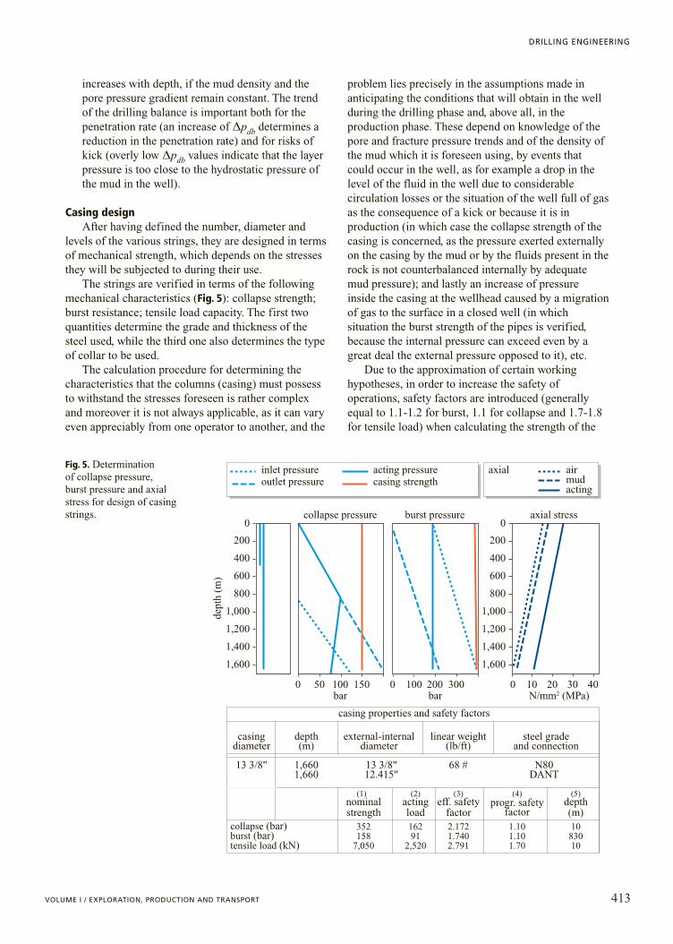
The strings are verified in terms of the followingmechanical characteristics (Fig. 5): collapse strength;burst resistance; tensile load capacity. The first twoquantities determine the grade and thickness of thesteel used, while the third one also determines the typeof collar to be used.
The calculation procedure for determining thecharacteristics that the columns (casing) must possessto withstand the stresses foreseen is rather complexand moreover it is not always applicable, as it can varyeven appreciably from one operator to another, and the
problem lies precisely in the assumptions made inanticipating the conditions that will obtain in the wellduring the drilling phase and, above all, in theproduction phase. These depend on knowledge of thepore and fracture pressure trends and of the density ofthe mud which it is foreseen using, by events thatcould occur in the well, as for example a drop in thelevel of the fluid in the well due to considerablecirculation losses or the situation of the well full of gasas the consequence of a kick or because it is inproduction (in which case the collapse strength of thecasing is concerned, as the pressure exerted externallyon the casing by the mud or by the fluids present in therock is not counterbalanced internally by adequatemud pressure); and lastly an increase of pressureinside the casing at the wellhead caused by a migrationof gas to the surface in a closed well (in whichsituation the burst strength of the pipes is verified,because the internal pressure can exceed even by agreat deal the external pressure opposed to it), etc.
Due to the approximation of certain workinghypotheses, in order to increase the safety ofoperations, safety factors are introduced (generallyequal to 1.1-1.2 for burst, 1.1 for collapse and 1.7-1.8for tensile load) when calculating the strength of the
413VOLUME I / EXPLORATION, PRODUCTION AND TRANSPORT
DRILLING ENGINEERING
bar bar N/mm2 (MPa)0 50 100 150 0 100 200 300 0 10 20 30 40
collapse pressure
inlet pressureoutlet pressure
acting pressurecasing strength
axial airmudacting
burst pressure
casing properties and safety factors
axial stress
casingdiameter
depth(m)
external-internaldiameter
linear weight(lb/ft)
steel gradeand connection
13 3/8" 1,6601,660
13 3/8"12.415"
68 # N80DANT
burst (bar)collapse (bar)
tensile load (kN)
(1) (2) (3) (4)progr. safety
factor
(5)
352158
7,050
16291
2,520
2.1721.7402.791
1.101.101.70
1083010
nominalstrength
actingload
depth(m)
eff. safetyfactor
200
400
600
800
1,000
1,200
1,400
1,600
0
200
0
400
600
800
1,000
1,200
1,400
1,600
dept
h (m
)
Fig. 5. Determination of collapse pressure, burst pressure and axial stress for design of casingstrings.

casing. These factors also depend on thecharacteristics of the material chosen, and it is soundpractice to use greater safety factors for pipes havinggreater strength, also in view of the higher stresses thatthese casings will have to withstand.
In addition to the method described above, othercasing design criteria can also be applied according toknowledge of the working situation, the reliability andaccuracy of the forecasts of the stresses to which thecasing will be subjected, the safety factors it is wished toadopt, the critical nature of the well to be designed (verydeep wells, with high pressure gradients, could require – if designed in the way most commonly followed – non-standard profiles in terms of diameter or thicknesswith a considerable increase in costs), and the presenceof acid gases (CO2, H2S) which could call for the use of special steels. But ultimately, whatever criteria isadopted, what in any circumstances has to be guaranteed,apart from the best practices in the planning and designphase, and respecting the internal procedures andregulations of each company or those required by theauthorities is, above all, the safety of the personnel andof the plants and the safeguarding of the environment.
The characteristics (diameter, grade, thickness andtype of collar) that the tubular material has to possessare codified by the American Petroleum Institute andcontained in Bulletins 5C2 (Performance Properties ofCasing, Tubing and Drill Pipe) and 5C3 (Formulasand Calculations for Casing, Tubing, Drill Pipe andLine Pipe Properties), to which all producers andusers make reference.
The various types of steel used for casings areindicated by codes consisting of a letter (H, J, K, N,C, P, Q, V) and a number (40, 55, 75, 80, 95, 110, 125,140, 150). The code N-80, for example, indicates thatthe steel has the characteristic composition ofmaterials of class N with a very specific hardness anda yield strength equal to 80,000 psi (circa 5.5 ⋅ 108 Pa).Going from class H steels to ones of class V and fromvalues of 40 to 150, the casings have increasinglyhigher mechanical characteristics, but also highercosts, so that it is important to foresee very accuratelythe stresses to which the casings will be subjected, soas to choose the most suitable materials from both theoperative and the economic standpoints.
Mud programmeThe mud most suitable for each phase of the hole is
formulated (defining its physical, chemical andrheological properties), and the surface equipmentmost suitable for its operation and maintenance isidentified on the basis of the trend of the pressuregradients, of the temperature, of the clearances in thediameter between hole-drill string and hole-casing, ofthe lithology of the formations to be traversed, of the
foreseen well problems (hole instability, circulationlosses, presence of formations having a plasticbehaviour, risk of string jamming due to differentialpressure, presence of corrosive acid gases), and of theparticular configuration that the well will have(vertical, deflected, horizontal). This also enables anestimate to be obtained of the costs to be borne, andthe most suitable of the various possible solutions tobe chosen, in terms of performance, cost andenvironmental impact.
Usually, in the first stretches of a well, that is, thoseto be drilled with large diameters (36'', 26''), water basemuds of quite simple composition are used, bothbecause the problems that can be met with in theshallower soils are limited, and because, in this way, inview of the considerable volumes concerned (300-400m3), the costs of the mud can be kept low. The materialsused in mud preparation, in these initial phases, arewater, bentonite and caustic soda. Then, as the drillingof the well goes ahead, in holes whose diameter isprogressively smaller (17 1�2'', 12 1�4'', 8 1�2'', 6''), andthe properties of the mud play an increasingly moreimportant role, polymers are added to reduce the filtrateand to increase the viscosity of the mud (starches,carboxymethylcellulose, cellulosic polyanionics), ordisperdants to make the system more fluid(lignosulphonates, polyacrylates), and, if necessary,weighting materials (baryte) according to the densitythat the mud should have in order to contain the layerfluids, lubricants, defoaming agents, inorganic salts(NaCl, KCl, CaCl2, K2CO3, silicates) and organic salts(formiates, acetates) to limit interactions of a chemicalnature between the water contained in the mud and anyformations of a clay nature that might be present. Asalready pointed out, according to the type of rocks to bedrilled, the configuration of the well and the expectedproblems, it may be decided (above all in the deeperphases) whether to use water base muds or oil basemuds. The latter are preferred when the formations tobe drilled are highly reactive, such as clays and salts, ordeviated and horizontal wells, in which there is greaterrisk of the drill string being jammed (generally causedby high differential pressures and large volumes offiltrates or by long stretches in which the string is incontact with the hole).
The density that the mud must have generallyincreases also with depth and consequently it isnecessary to optimize its rheological characteristics(plastic viscosity, yield point and thixotropicproperties) and solid content (to diminish head lossesin the drilling rods and in the annulus), transportcapacity (to remove the cuttings from the well and tokeep it clear), and filtration (to minimize interactionsbetween fluid and rock). Particular care must generallyalso be devoted to mud handling and maintenance, to
414 ENCYCLOPAEDIA OF HYDROCARBONS
DRILLING AND COMPLETION OF WELLS
ensure that excessive volumes of refluents are notproduced (in fact, a certain quantity of mud, whendiameters and volumes diminish, has to be eliminatedand disposed of). For this reason an accurate selectionmust be made of the surface equipment for treating themud, such as shakers (which make a first importantseparation of the cuttings from the mud), desilters anddesanders (used to remove the solid particles of verysmall size which the shakers are unable to intercept),centrifuges (to recover the barytes which otherwisecould be lost), the degasser (for removing any gaspresent in the mud) and the refluent treatment system(which recovers the water from the mud to be disposedof, thus reducing the volumes to be dumped).
Management of drilling fluid is a very criticalaspect for achieving the set objectives, and indeedthere are specialized operators in the plant dedicated toit, seeing to the continuous adaptation of the fluid tothe particular well situations.
A problem that the programmer has to face is thatof disposal of drilling wastes (cuttings, excessivevolumes of mud and those resulting from theirreplacement with cement mortar or with thecompletion fluid, and plant wash waters). This involveshundreds of tons of solids and several hundred if notsome thousands of cubic metres of muds and of washwaters. This huge mass of waste products is normallystored in a large pit dug parallel to the drill rig (shakerside) and duly waterproofed. The size of this pit isproportional to the volume of wastes produced, to theestimated duration of the drilling operations and to thechoice to be made between the continuous disposal ofwhat is produced or storage and disposal at the end ofoperations. Disposal of the waste products is entrustedto specialized firms which treat them and dispose ofthem in accordance with the regulations in force.
Lastly, with regard to costs, drilling muds canaccount for between 1/100 and 1/10 of the total costof a well, depending on their complexity, which meansthat they can cost between 100 and more than 1,000thousand euro per well, even if from a purelyoperative standpoint they can have a far greaterweight on the final result. The treatment and disposalof wastes can have a similar, or even higher, impact onthe costs and for this reason more and more attentionis being dedicated to them.
Hydraulic programmeThe definition of the hydraulic programme is closely
dependent on the density of the mud foreseen for eachphase, and therefore on the development of the porepressure gradient, on the rheological characteristics asindicated in the mud programme, on borehole diameterand relative depths, on the composition of the drillstrings, on the bits and the equipment available to the rig,
in particular the pumps, the drilling swivel and thesurface hydraulic circuit.
As stated, the mud is pumped into the well usingreciprocating piston pumps through surface piping,drilling strings, and the bit, after which it rises in theannulus taking with it the cuttings which it deposits onthe shaker. The capacity, the pumping pressure and therheological characteristics are the variables to be usedin carrying out the hydraulic programme.
A good hydraulic programme must foresee a rate atwhich the mud issues from the bit nozzles that willoptimize the drilling process, a return rate through theannulus that will promptly convey the cuttings to thesurface, and the use of a mud having characteristicsthat minimizes pressure drops in the annulus andtherefore the well bottom pressure.
The total pressure losses in the circuit (string, bit,annulus and surface pipes) should be distributed asfollows: between 70 and 80% in the lines, between 10and 15% in the bit nozzles, between 5 and 15% in theannulus and only a very small part (1-2%) in thesurface pipes. The discharge of the mud (such as toensure an ascending velocity of not less than 30-40m/min), usually varies between 4,000 l/min in shallowboreholes (17 1�2'') and 2,500-2,800 l�min inintermediate boreholes (12 1�4'') and 1,800-2,000l/min in the 8 1�2'' borehole, while pressure losses varybetween a few tens of bar in the bigger holes and 300bar in the smaller ones.
Special attention has to be taken in controlling theequivalent mud density, which increases in the annuluswith increased discharge of the pumps andconsequently with increased ascending velocity andpressure losses. It is also advisable to maintain theoptimal rheological characteristics of the mud becausethese values will influence the increase in equivalentdensity. For example, in drilling a 12 1�4'' hole at3,000 m and with a mud discharge of approximately2,800 l�min, there will be an ascending velocity ofabout 45 m/min and a bottomhole pressure increaseequal to that which would be obtained, with zerodischarge, by increasing the density by 0.1 kg�dm3; in some circumstances this increase could induceabsorption losses or fracturing. It is evident that as themud density increases and as the difference betweenlayer pressure and fracturing pressure is reduced(in deep wells with high pressure gradients this difference could be extremely small, in the order ofabout 10 bar), the hydraulic aspect must be treatedwith particular care, as any excessive pressure lossescould cause the equivalent circulating mud density toincrease too much with harmful effects on the integrityof the rock. This could in fact become fractured, givingrise to circulation losses which, in their turn, couldgive rise to kicks and, in extreme cases, of blowouts.
415VOLUME I / EXPLORATION, PRODUCTION AND TRANSPORT
DRILLING ENGINEERING
Cementing programmeAfter defining the casing profiles, depth of
lowering the strings, their dimension and diameterclearances, in keeping with the foreseen temperatures,pressure gradients and the times necessary to conductcementing operations in a safe manner, the next step isto plan these and to formulate the most suitablecement mortars for the purpose.
For the cement slurry to be used in each phase thepumpability times have to be determined (i.e. the timethe slurry has to remain fluid and pumpable before theprocesses of hydration, hardening and setting start) aswell as the required rheological and mechanicalcharacteristics; following which comes theformulation properly so termed. It is also necessary todefine how the strings are to be equipped (number andposition of centralizers and scrapers) so as toguarantee an acceptable centring of the string in thehole, so as to assist the rise of the cement slurry in theannulus in the most regular manner possible, and toincrease the chance that the operation will besuccessful.
The cement slurrys used for surface casings requireno particular measures, as the fairly moderatetemperatures encountered at shallow depths (30-70°C),and the large clearances in the diameter with limitedpressure losses do not pose any particular operativeproblems. In these cases, class G-HSR cement mixeswith water is normally used at a density of around 1.90g/cm3, with some accelerating agent (CaCl2, seawater)to reduce pumping times which could otherwise be toolong. At times, especially in highly porous andpermeable formations or ones that are littleconsolidated or even fractured, it might be necessaryto use low-density mortars (between 1.20 and 1.60g/cm3), according to circumstances. These areobtained by adding to the basic slurry somelightweight materials such as diatomite, bentonite,etc., in variable percentages (from 1 up to 10-20 ormore). We have said that the surface casing, preciselybecause it has to support all the subsequent casings,has to be cemented with the cement rising to thesurface. The formations concerned are howevernormally fairly weak and the fracture gradient quitelow, so that it is difficult for the mortar, even iflightened, to rise to the surface in just a single stagewithout creating some absorption. It is thereforeadvisable to carry out cementing in two stages, thefirst one through the shoe for a rise that will cover atleast 50% of the length of the hole. After the cementhas set, small-diameter tubing should be lowered intothe annulus and slurry should be pumped into thisuntil it reaches the wellhead. The tubing will then bequickly extracted from the slurry before it starts to set,for which reason it is advisable to check beforehand
that the setting times are sufficiently long to allow thisoperation to be performed.
As depth increases, and with it the temperature,cements (slurries) become more and more complexand require the use of additives having specificfunctions, such as filtrate reducers (to avoid thepremature dehydration of the cement), fluidizers (tooptimize the theology and reduce pressure losses and,therefore, the risks of fracturing the formations duringpumping and displacement of the cement), retardants(to extend times of pumpability according to theforeseen cementing duration, times which becomeprogressively more critical with increasingtemperature), weight materials such as barite,haematite or manganese oxide (to obtain a mortar at adensity adequate to balance the layer pressure), anddefoaming agents. The pumpability times required, canvary from just a few hours, to more than 10 hours,depending on the depth to which the casing has to belowered, the volumes to be pumped, and thedisplacement flows admissible for the availablesurface equipment (pumps, cementers), while thefiltrate may be between 500-1,000 cm3�30 min (in thecase of cement without filtrate reducers) and 20-30cm3�30 min (in the case of cement with filtratereducers). When gas migration risks are foreseen, thedensity may even be of higher values than 2.25 g/cm3,and the mechanical strength, lastly, should as soon aspossible after setting reach acceptable values so as tomake it possible to resume drilling within a short timeand under safe conditions (35 bar), and then to be ableto drill the column (70 bar) when the well is broughtinto production.
If particular well situations are foreseen, such asfor example the presence of fractured formations inwhich there might be considerable absorption andcirculation losses, or if mineralized levels have to becrossed which might give rise to gas migration,compromising the integrity of the hardened cementand its hydraulic seal, or, lastly, if it is foreseen to haveto cement zones of high temperature (>120°C),mortars are used which have an even more complexcomposition using specific products, such as speciallightweight materials, gas blocking additives of anorganic or inorganic nature (polymers, lampblack) orcements having high concentrations of siliceousmaterial. Very often, and in particular in cementing thedeepest casings (9 5�8'', 7''), cements withdifferentiated characteristics and multi-stagecementing are used.
Regarding the operative aspects of cementing, anumber of cubic metres of a buffer cushion formed bywater, viscosity agents and retardants, are usuallypumped in front of the cement, to separate it from themud in the well, and to prevent the properties of the
416 ENCYCLOPAEDIA OF HYDROCARBONS
DRILLING AND COMPLETION OF WELLS
cement (in particular its rheology and pumpabilitytimes) from contamination and consequentdeterioration. Following this buffer cushion, severalcubic metres of light cement with good rheologicalcharacteristics can be used, for the purpose of properlycleaning – as conditions of turbulent flow can easilybe reached – the mud from annulus and the cake fromthe walls of the hole, which could both, if notremoved, compromise the outcome of the cementing.Following this light cement the slurry proper is placed,which is of optimal density and composition toguarantee hydraulic seal and the programmedmechanical strength.
With regard to the column equipment, in verticalwells, and according to the depth, after a first centringin which a centralizer is positioned for each pipe about1,000-1,500 m from the bottomhole, in the followingcentring one centralizer is placed for every three pipesup to the surface. In deflected and horizontal wells, thecentring obviously increases, especially in the buildupor drop-off stretches, arriving even at 2-3 centralizersper pipe. As already recalled, there are computerprogrammes making it possible to define the mostappropriate centring according to the particularfeatures of the well.
For wells in which the temperature is higher than120-130°C, it is very important to formulate thecement on the basis of laboratory tests conducted undersimulated working conditions and using the sameproducts that will actually be made available on the site(from cement to mixing water and chemical additives).This practice is recommended because even minordifferences in characteristics and concentration of theadditives at the temperatures considered can havedramatic effects on pumpability times (reducing themfrom many hours to just a few hours) and therefore onthe success of the operation. Premature setting of thecement, which can occur when this is still inside thecolumn, can cause serious operational drawbacks,ranging from the non-cementation of the casing shoe tothe insufficient isolation of the mineralized levels, tothe inadequate anchorage of the casing and even toconsiderable increase in the time of bringing the wellback under control and hence of the costs.
Cementing of the casing may be total, i.e. the riseof the cement affects the whole annulus from the shoeup to the surface (with a rise of even more than 4,000-5,000 m), or partial (with a rise of 1,000-2,000 m),depending on the particular situation of the well. Thisdecision influences the composition of the cement, itscharacteristics, the volumes of cement and additives tobe used and, therefore, the costs, which can vary from100 up to 300-500 thousand euro.
It has been stated that the result of cementing isusually controlled by means of recording a specific
log, indicated by the code CBL-VDL (Cement BondLog-Variable Density Log). This log should berecorded when the cement has set firmly, i.e. somedays after cementing has been performed. At times itscontrol is postponed to when the logs included in thedrilling programme are recorded, that is, prior to thelowering of the next casing. CBL-VDL is a sonic logand measures the velocity at which the sound wavecrosses the metal-cement or cement-formation stretch.The stronger the bond between these materials, thequicker the crossing will be. The recording of the VDLcomponent gives more specific information on themetal-cement or the cement-formation bond. If insteadit is preferred to have a precise indication of thecement rising immediately after cementing, athermometric log can be recorded: it is known that thecement sets with the development of heat so that bysending a thermometer down into the well a few hoursafter the end of cementing, the temperature variationwill indicate the level to which the cement has risen.However the thermometric log does not provideindications on the quality of the bond created (metal-cement-formation) and thus is not much used.
Cementing is programmed so that the cementslurry will rise to cover the formations concerned. Thetechnician calculates the volume of cement necessary,also assessing any caving, and adds a quantity ofcement to be on the safe side, but even so the resultmight not be the desired one due to:• Channelling of the cement, which means that some
levels might not have an acceptable bond: thisoccurs when there is caving and the mortar has notbeen pumped in such a way as to ensure those con-ditions of motion that will guarantee the optimaldisplacement of the mud.
• Losses (absorption) during displacement so thatsome levels are not cemented.
• Uncertainty as to the separation of pressure levelsor different mineralization: this could cause trans-fer of fluid from one level to another.In these cases, remedial cementing might be
necessary, or cement squeezes. Recementing iscarried out by opening a number of holes in thecasing at the base and at the summit of the zone to berecemented. A bridge plug is then lowered and fixedin the casing just above the holes made at the bottom.Circulation is then verified between the two series ofholes and, if the result is positive, recementing isperformed. The rods are then extracted leaving thebridge plug in position (this will be subsequentlymilled prior to resuming drilling or other casingoperations) and circulating mud at the height of theupper holes so as to expel any excess cement from thecasing. The remedial cementing can then be checkedwith a CBL-VDL.
417VOLUME I / EXPLORATION, PRODUCTION AND TRANSPORT
DRILLING ENGINEERING
If communicating levels have to be isolatedinstead, one or more squeeze operations must becarried out, consisting basically in pumping smallvolumes of mortar under pressure. Holes should beopened in the casing only where injection will takeplace, after which a bridge plug is fixed above theholes as during recementing. A small quantity ofcement is injected through the bridge plug and theholes. A special block valve installed in the bridgeplug will stop the mortar from reentering the casing. Ifmore than one squeeze operation has to be performed,they should be carried out from below and rising,applying the same technique for each one. Whetherthere is one bridge plug or more, they have to bemilled when operations are resumed. The success ofthese cement squeezes can also be controlled bycarrying out a new CBL-VDL and comparing it withthe preceding one.
Choice of bitsThe choice of bits is generally made taking the
performance of those previously used in analogouswells and contexts as a reference or in lithotypesthat will foreseeably be encountered in the wellunder examination. Obviously the bits chosen willbe those that have performed best in terms ofpenetration rate and cost per metre drilled. Thisassessment also takes into consideration the timethat the bit remains at the bottom and its startingcost as well as the penetration rate. If thisinformation is not available, drillability tests can berun in the laboratory by means of measurement ofcores, drill cuttings or corresponding surfacecuttings; in this case, detailed forecasts cannot bemade, but at least there will be some indication as tothe family of bits most suitable for the variousformations expected.
418 ENCYCLOPAEDIA OF HYDROCARBONS
DRILLING AND COMPLETION OF WELLS
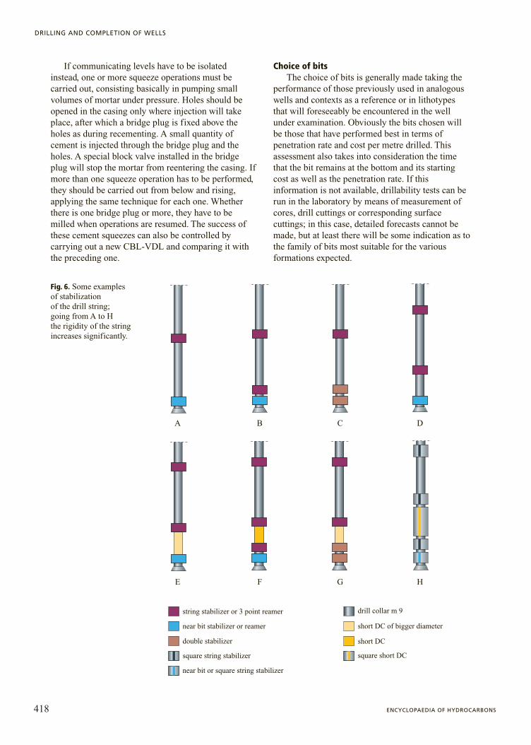
Fig. 6. Some examples of stabilization of the drill string; going from A to H the rigidity of the stringincreases significantly.
A B C D
E F G H
near bit stabilizer or reamer
double stabilizer
square string stabilizer
near bit or square string stabilizer
square short DC
drill collar m 9
short DC of bigger diameter
short DC
string stabilizer or 3 point reamer

The programming expert has a vast range of bitsavailable (roller cone bits with milled steel teeth, insertroller bits, PDC or Polycrystalline Diamond bits,diamond bits, etc.). The choice of which type to useobviously depends on the formations to be drilled, sothat the more information that is available on these, themore effective the choice will be. For surfaceformations which it is assumed are of low compaction,three-cone long-toothed bits (with metal teeth orinserts) are used, which permit high penetration rateswith little weight and a large number of rpm. As depthincreases and the formations become harder and morecompact, bits are used with shorter inserts which,though on the one hand have slower penetration rates,remain in the well for more hours before getting wornout; the drilling parameters foresee an increase in theweight of the bit and a reduction in the number of rpm.For drilling particularly hard formations (compactlimestones, dolomites, sandstones) of considerablethickness, it will be more convenient to use diamondcutters whose penetration rates are fairly slow with afairly high number of rpm and little weight on the bit,as they operate more by abrasion than by compressionand cutting of the rock. PDC bits are instead verysuitable for drilling through hard clays, marls andlimestones which, as a rule, require intermediatevalues of weight and velocity of rotation of the string.In this way, the penetration rate is slower but the bitremains at the bottomhole decidedly longer than three-cone bits do. Lastly, in deep drilling and in small holediameters, the use of roller bits is not very convenientas they are much weaker from a mechanical standpoint(no significant weights can be applied to the bit) andconsequently their performance is far inferior to thatof the bits which have no parts in motion.
This information is entered in the drillingprogramme and although sometimes veryapproximate, it serves to give some idea of the typesof bit and the drilling parameters to be applied. It willbe the drilling site technician’s job during the actualconstruction of the well to decide on the type to beused after having observed the real condition (wearand performance) of the bits lowered into the well, thephysical and mechanical characteristics of theformations and the effectiveness of the parametersused (weight, velocity of rotation) in terms ofpenetration rate, cost per metre drilled, as continuouslyprocessed by the mud logging unit (see below: Controlof drilling operations).
It should be borne in mind that, when the bit isworn, it has to be extracted and replaced. The operationof drilling bit change (tool) takes just a few hours at ashallow depth, but many hours at medium and greatdepths. These times are idle periods (which increase thedrilling cost) and so it is essential to use the bit which,
in the specific case, will guarantee the maximumpenetration with the most suitable parameters, and willremain at the bottomhole as long as possible.
Lastly, the mud circulation is of great importancefor the penetration of the bit into shallow and softformations. In these cases, the rate at which the nozzlevelocity must be kept as high as possible (more than100 m�s) so as to increase, with the jet velocity, thepenetration of the bit and to keep the teeth as clean aspossible (as the bits tend to balling up, especially whendrilling through clay). The choice of the nozzlediameter must therefore be made very carefully. In theharder formations, the effect of the drilling mud jet onthe penetration rate is clearly less, so that the choice ofnozzle diameter is no longer so important, althoughproper cleaning of the bit and of the bottomhole isessential for achieving the best performance.
StabilizationThe drill string is made up, as has been seen, of an
assembly of pipes and equipment which connect thebit to the wellhead, known as the Bottom HoleAssembly (BHA). In constructing it the technician hasavailable bits, Drill Collars (DC), Drill Pipes (DP),Heavy-Weight pipes (HW), stabilizers, roller reamers,shock absorbers, jars, a Positive Displacement Motor(PDM) and turbines, Measurements While Drilling(MWD) and various reducing units. All these items ofequipment have different diameters depending on thediameter of the hole that has to be drilled; thediameters of the drill pipes are of 5 1�2'', 5'' and 3 1�2'',those of the drill collars are from 12'' to 4 3/4'', andthose of all the other items of equipment must becompatible with the drill pipes and drill collars used.
The strings are formed on the basis of the diameterof the hole to be drilled, the hardness of the formation,the inclination of the borehole, and the type of bit tobe used (Fig. 6). Starting from the bit, a typical stringcan be made up as follows: bit � near-bit stabilizer �pony drill collar � stabilizer (or roller reamer) + shockabsorber � 1-3 drill collars � jar � 1-3 drill collars �5-10 HW pipes � normal pipes up to the surface. Theend part of the string has to be very stiff to guaranteethe regularity of the hole and to ensure that it willremain vertical. The number of drill collars musttherefore be such as to ensure the weight to be appliedto the bit, while the purpose of the jar is to provide thedownward or upward strokes in the event of the stringbeing jammed.
It is best, especially if permeable formations areencountered, to insert stabilizers every 2 or 3 drillcollars to reduce the possibility of the collarsbecoming jammed (the drill collars, being smooth andof large diameter can easily lean against the walls ofthe hole and stay stuck there during the intervals when
419VOLUME I / EXPLORATION, PRODUCTION AND TRANSPORT
DRILLING ENGINEERING
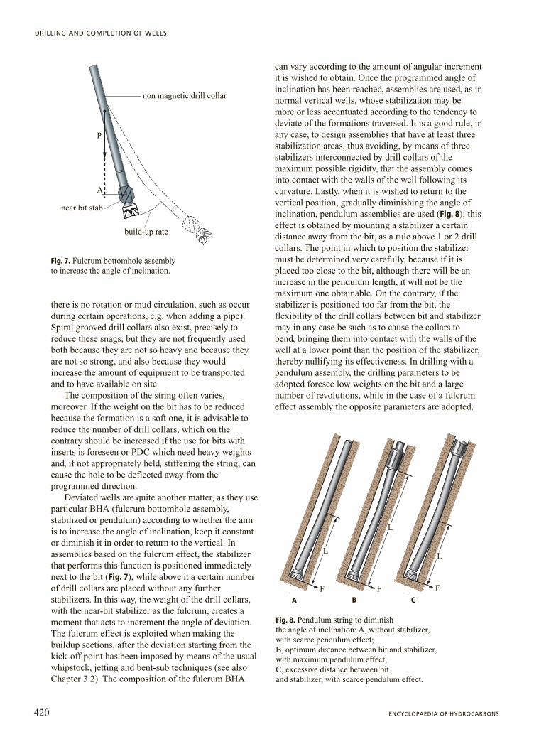
there is no rotation or mud circulation, such as occurduring certain operations, e.g. when adding a pipe).Spiral grooved drill collars also exist, precisely toreduce these snags, but they are not frequently usedboth because they are not so heavy and because theyare not so strong, and also because they wouldincrease the amount of equipment to be transportedand to have available on site.
The composition of the string often varies,moreover. If the weight on the bit has to be reducedbecause the formation is a soft one, it is advisable toreduce the number of drill collars, which on thecontrary should be increased if the use for bits withinserts is foreseen or PDC which need heavy weightsand, if not appropriately held, stiffening the string, cancause the hole to be deflected away from theprogrammed direction.
Deviated wells are quite another matter, as they useparticular BHA (fulcrum bottomhole assembly,stabilized or pendulum) according to whether the aimis to increase the angle of inclination, keep it constantor diminish it in order to return to the vertical. Inassemblies based on the fulcrum effect, the stabilizerthat performs this function is positioned immediatelynext to the bit (Fig. 7), while above it a certain numberof drill collars are placed without any furtherstabilizers. In this way, the weight of the drill collars,with the near-bit stabilizer as the fulcrum, creates amoment that acts to increment the angle of deviation.The fulcrum effect is exploited when making thebuildup sections, after the deviation starting from thekick-off point has been imposed by means of the usualwhipstock, jetting and bent-sub techniques (see alsoChapter 3.2). The composition of the fulcrum BHA
can vary according to the amount of angular incrementit is wished to obtain. Once the programmed angle ofinclination has been reached, assemblies are used, as innormal vertical wells, whose stabilization may bemore or less accentuated according to the tendency todeviate of the formations traversed. It is a good rule, inany case, to design assemblies that have at least threestabilization areas, thus avoiding, by means of threestabilizers interconnected by drill collars of themaximum possible rigidity, that the assembly comesinto contact with the walls of the well following itscurvature. Lastly, when it is wished to return to thevertical position, gradually diminishing the angle ofinclination, pendulum assemblies are used (Fig. 8); thiseffect is obtained by mounting a stabilizer a certaindistance away from the bit, as a rule above 1 or 2 drillcollars. The point in which to position the stabilizermust be determined very carefully, because if it isplaced too close to the bit, although there will be anincrease in the pendulum length, it will not be themaximum one obtainable. On the contrary, if thestabilizer is positioned too far from the bit, theflexibility of the drill collars between bit and stabilizermay in any case be such as to cause the collars tobend, bringing them into contact with the walls of thewell at a lower point than the position of the stabilizer,thereby nullifying its effectiveness. In drilling with apendulum assembly, the drilling parameters to beadopted foresee low weights on the bit and a largenumber of revolutions, while in the case of a fulcrumeffect assembly the opposite parameters are adopted.
420 ENCYCLOPAEDIA OF HYDROCARBONS
DRILLING AND COMPLETION OF WELLS
A
P
near bit stab
build-up rate
non magnetic drill collar
Fig. 7. Fulcrum bottomhole assembly to increase the angle of inclination.
A CF F F
L
L
L
Fig. 8. Pendulum string to diminish the angle of inclination: A, without stabilizer, with scarce pendulum effect; B, optimum distance between bit and stabilizer, with maximum pendulum effect; C, excessive distance between bit and stabilizer, with scarce pendulum effect.
A B C
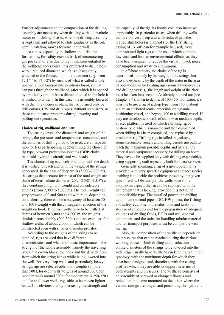
Further adjustments to the composition of the drillingassembly are necessary when drilling with a downholemotor or in sliding, that is, when the drilling assemblyis kept firm and allowed to slide gradually as the bit,kept in rotation, moves forward in the well.
At times, especially in shallow and offshoreformations, for safety reasons (risk of encounteringgas pockets) or else due to the limitations entailed bythe wellhead accessories, it is preferred to drill a holewith a reduced diameter, which is subsequentlywidened to the foreseen nominal diameter (e.g. from12 1�4'' to 17 1�2'') by means of what is called a holeopener (a tool lowered into position closed, so that itcan pass through the wellhead, after which it is openedhydraulically until it has a diameter equal to the hole itis wished to widen). In this case, the assembly loweredwith the hole opener is plain, that is, formed only bydrill collars, HW and drill pipes, without stabilizers, asthese could cause problems during lowering andpulling-out operations.
Choice of rig, wellhead and BOPThe casing levels, the diameters and weight of the
strings, the pressures and temperatures concerned, andthe volumes of drilling mud to be used, are all aspectsmore or less participating in determining the choice ofrig type, blowout prevention systems (BOP, chokemanifold, hydraulic circuit) and wellheads.
The choice of rig is closely bound up with the depthit is wished to reach and with the weight of the stringsconcerned. In the case of deep wells (5,000-7,000 m),the strings that account for most of the total weight arethose of intermediate diameter (20'', 13 3�8'', 9 5�8'') asthey combine a high unit weight and considerablelengths (from 2,000 to 5,000 m). The total weight canvary between 400 and 500 t and with mud, dependingon its density, there can be a buoyancy of between 50and 100 t-weight with the consequent reduction of theweight on hook. If normal wells have to be drilled, atdepths of between 3,000 and 4,000 m, the weightsdiminish considerably (200-300 t) and are even less forshallow wells, of about 2,000 m, which can beconstructed even with smaller diameter profiles.
According to the weights of the strings to behandled, rigs are used that have differentcharacteristics, and what is of basic importance is thestrength of the whole assembly, namely the travellingblock, the crown block, the hook and the derrick floorfrom which the string hangs while being lowered intothe well. For very deep wells and particularly heavystrings, rigs are selected able to lift weights of more than 500 t, for deep wells weights of around 300 t, formedium wells around 300 t, for medium wells 250-270 tand for shallower wells, rigs able to bear even lighterloads. It is obvious that by increasing the strength and
the capacity of the rig, its hourly cost also increasesappreciably. In particular cases, when drilling wellsthat are not very deep and with reduced profiles(called slim holes) is planned (for the first string,casing of 13 3/8'' can for example be used), verycompact and light rigs can be used, which combinelow costs and limited environmental effects, as theyhave been designed to reduce the visual impact, noise,consumption and waste to a minimum.
In offshore activity, the choice of the rig isdetermined, not only by the weight of the strings, butalso and especially by the depth of the water in the areaof operations, as for floating rigs (semisubmersible rigsand drilling vessels), the length and weight of the risermust be taken into account. As already pointed out (seeChapter 3.4), down to depths of 100-150 m of water, it ispossible to use a rig of jackup type, from 150 to about400 m an anchored semisubmersible or dynamicpositioning vessel, and beyond 400 m a drilling vessel. Ifthey are development wells of shallow or medium depth,a fixed platform is used on which a drilling rig ofonshore type which is mounted and then dismantledwhen drilling has been completed, and replaced by aproduction rig. Drilling rigs installed on jackups,semisubmersible vessels and drilling vessels are built toreach the maximum possible depths and have all thematerial and equipment necessary for drilling on board.They have to be supplied only with drilling expendables,using supporting craft especially built for these services.
Generally speaking, a rig of a given potential isprovided with very specific equipment and accessoriesenabling it to tackle the problems posed by that giventype of wells. Obviously if the wells have someanomalous aspect, the rig can be supplied with theequipment that is lacking, provided it is not of anunmodifiable type. The installed power, the drillingequipment (normal pipes, DC, HW pipes), the fishingand safety equipment, the silos, bins and tanks forstorage of products and for the preparation of adequatevolumes of drilling fluids, BOPs and well-controlequipment, and the units for handling tubular materialand for transport purposes, must be compatible withthe rig.
Also, the composition of the wellhead depends onthe pressures that can be reached during the variousworking phases – both drilling and production – andon the diameters of the strings to be lowered into thewell. Rigs usually have wellheads in keeping with theirtypology, with the maximum depth for which theyhave been designed and, therefore, with the casingprofiles which they are able to support in terms ofboth weights and pressures. The wellhead consists ofan assembly of screwed or clamped flanges andreduction units, one mounted on the other, where thevarious strings are lodged and permitting the hydraulic
421VOLUME I / EXPLORATION, PRODUCTION AND TRANSPORT
DRILLING ENGINEERING
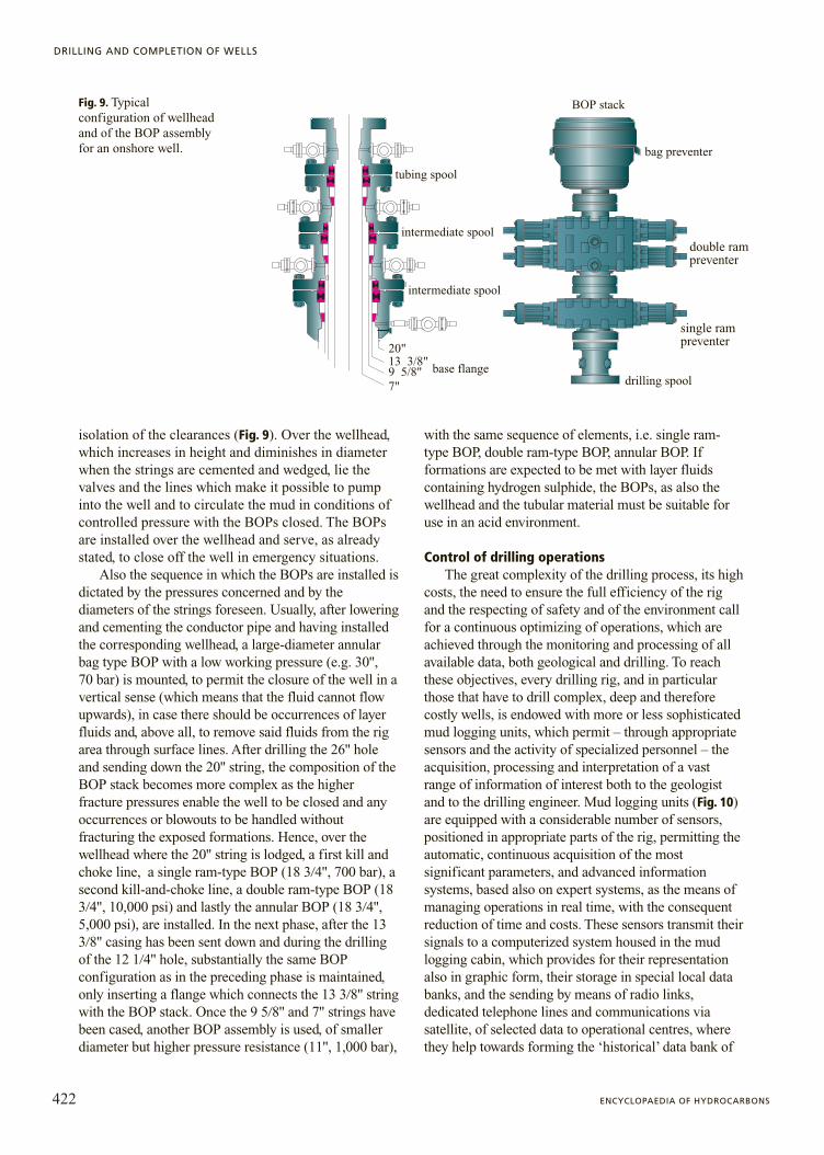
isolation of the clearances (Fig. 9). Over the wellhead,which increases in height and diminishes in diameterwhen the strings are cemented and wedged, lie thevalves and the lines which make it possible to pumpinto the well and to circulate the mud in conditions ofcontrolled pressure with the BOPs closed. The BOPsare installed over the wellhead and serve, as alreadystated, to close off the well in emergency situations.
Also the sequence in which the BOPs are installed isdictated by the pressures concerned and by thediameters of the strings foreseen. Usually, after loweringand cementing the conductor pipe and having installedthe corresponding wellhead, a large-diameter annularbag type BOP with a low working pressure (e.g. 30'', 70 bar) is mounted, to permit the closure of the well in avertical sense (which means that the fluid cannot flowupwards), in case there should be occurrences of layerfluids and, above all, to remove said fluids from the rigarea through surface lines. After drilling the 26'' holeand sending down the 20'' string, the composition of theBOP stack becomes more complex as the higherfracture pressures enable the well to be closed and anyoccurrences or blowouts to be handled withoutfracturing the exposed formations. Hence, over thewellhead where the 20'' string is lodged, a first kill andchoke line, a single ram-type BOP (18 3�4'', 700 bar), asecond kill-and-choke line, a double ram-type BOP (183�4'', 10,000 psi) and lastly the annular BOP (18 3�4'',5,000 psi), are installed. In the next phase, after the 133�8'' casing has been sent down and during the drillingof the 12 1�4'' hole, substantially the same BOPconfiguration as in the preceding phase is maintained,only inserting a flange which connects the 13 3�8'' stringwith the BOP stack. Once the 9 5�8'' and 7'' strings havebeen cased, another BOP assembly is used, of smallerdiameter but higher pressure resistance (11'', 1,000 bar),
with the same sequence of elements, i.e. single ram-type BOP, double ram-type BOP, annular BOP. Ifformations are expected to be met with layer fluidscontaining hydrogen sulphide, the BOPs, as also thewellhead and the tubular material must be suitable foruse in an acid environment.
Control of drilling operationsThe great complexity of the drilling process, its high
costs, the need to ensure the full efficiency of the rigand the respecting of safety and of the environment callfor a continuous optimizing of operations, which areachieved through the monitoring and processing of allavailable data, both geological and drilling. To reachthese objectives, every drilling rig, and in particularthose that have to drill complex, deep and thereforecostly wells, is endowed with more or less sophisticatedmud logging units, which permit – through appropriatesensors and the activity of specialized personnel – theacquisition, processing and interpretation of a vastrange of information of interest both to the geologistand to the drilling engineer. Mud logging units (Fig. 10)are equipped with a considerable number of sensors,positioned in appropriate parts of the rig, permitting theautomatic, continuous acquisition of the mostsignificant parameters, and advanced informationsystems, based also on expert systems, as the means ofmanaging operations in real time, with the consequentreduction of time and costs. These sensors transmit theirsignals to a computerized system housed in the mudlogging cabin, which provides for their representationalso in graphic form, their storage in special local databanks, and the sending by means of radio links,dedicated telephone lines and communications viasatellite, of selected data to operational centres, wherethey help towards forming the ‘historical’ data bank of
422 ENCYCLOPAEDIA OF HYDROCARBONS
DRILLING AND COMPLETION OF WELLS
20"
7"
13 3/8"9 5/8" base flange
intermediate spool
intermediate spool
tubing spool
BOP stack
bag preventer
double rampreventer
single rampreventer
drilling spool
Fig. 9. Typical configuration of wellhead and of the BOP assembly for an onshore well.
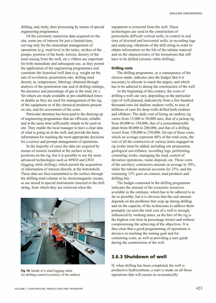
drilling, and, lastly, their processing by means of specialengineering programmes.
Of the extremely numerous data acquired on thesite, some are of interest for just a limited time,serving only for the immediate management ofoperations (e.g. mud level in the tanks, strokes of thepumps, position of the hook, torsion, density of themud issuing from the well, etc.). Others are importantfor both immediate and subsequent use, as they permitthe application of the engineering programmes andconstitute the historical well data (e.g. weight on bit,rate of revolution, penetration rate, drilling muddensity in, temperature, lithology obtained throughanalysis of the penetration rate and of drilling cuttings,the presence and percentage of gas in the mud, etc.).Yet others are made available at pre-established timesor depths as they are used for management of the rig,of the equipment or of the chemical products presenton site, and for assessment of the costs.
Particular attention has been paid to the drawing upof engineering programmes that are efficient, reliableand at the same time sufficiently simple to be used onsite. They enable the local manager to have a clear ideaof what is going on in the well, and provide the basicinformation for reaching the most appropriate decisionsfor a correct and prompt management of operations.
In the majority of cases the data are acquired bymeans of sensors installed at the surface in keypositions on the rig, but it is possible to use far moreadvanced technologies such as MWD and LWD(logging while drilling), which permit the acquisitionof information of interest directly at the bottomhole.These data are then transmitted to the surface throughthe drilling mud column or by electromagnetic means,or are stored in special instruments inserted in the drillstring, from which they are retrieved when the
equipment is extracted from the well. Thesetechnologies are used in the construction ofparticularly difficult vertical wells, in control in realtime of diverted and horizontal wells, in recording logsand analysing vibrations of the drill string in order toobtain information on the life of the tubular materialand on the characteristics of the formations that stillhave to be drilled (seismic while drilling).
Drilling costsThe drilling programme, as a consequence of the
choices made, indicates also the budget that it isnecessary to allocate to reach the targets, and whichhas to be adhered to during the construction of the well.
At the beginning of this century, the costs ofdrilling a well can vary, depending on the particulartype of well planned, indicatively from a few hundredthousand euro for shallow onshore wells, to tens ofmillions of euro for deep wells drilled both onshoreand offshore. The daily cost of hiring an onshore rigvaries from 15,000 to 50,000 euro, that of a jackup rigfrom 60,000 to 150,000, that of a semisubmersibleplant from 80,000 to 200,000, and that of a drillingvessel from 150,000 to 250,000. On top of these costs,which on average represent 40% of the total costs, thecost of all the contractors at various times engaged onrig works must be added, including site preparation,geological surveillance, recording logs, performingcementing works, managing the mud, control ofdeviation operations, waste disposal, etc. These costsof the auxiliary contractors amount on average to 20%,while the tubular material accounts for 25%, and theremaining 15% goes on cement, mud products anddrilling bits.
The budget contained in the drilling programmeindicates the amount of the economic resourcesavailable in the estimate, which has to be adhered to asfar as possible; but it is obvious that the real amountdepends on the problems that crop up during drillingand on the capacity of the technicians to address thempromptly (as seen the total cost of a well is stronglyinfluenced by working times, as the hire of the rig isthe highest cost item in percentage terms) and withoutcompromising the achieving of the objectives. It isthus clear that a good programming of operations isdecisive in reaching the mining goal and forcontaining costs, as well as providing a sure guideduring the construction of the well.
3.6.3 Shutdown of well
If, when drilling has been completed, the well isproductive hydrocarbons, a start is made on all thoseoperations that will ensure its economically
423VOLUME I / EXPLORATION, PRODUCTION AND TRANSPORT
DRILLING ENGINEERING
Fig. 10. Inside of a mud logging cabin for drilling control (courtesy of the author).

advantageous working, whereas if, on the contrary, itshould prove to be barren or in any case noteconomically exploitable, it will be shut down. Wellshutdown entails the restoring of the initial conditionsof the section of the well not lined and possibly alsothe lined part, if separation of the permeable levels ofdifferent pressure is not assured.
The purpose of these measures is to prevent thetransfer of fluids from one level to the other. This isachieved, in the free hole, by isolating the various levelswith cement plugs to be positioned at the impermeableseparation levels. The cement plug is made by loweringpipes without a bit down to the lower level of the hole tobe filled in and, after fixing a bridge plug there,pumping a quantity of slurry such as to guarantee thehydraulic separation of the levels concerned. Once thepipes have been pulled out, and after waiting for thecement to set, they are lowered again this time with thebit to verify that the plug is hard and at the right depth.Regarding the isolation of the cased well levels, notaffected by the cementing of the column, the squeezetechnique described above is carried out. A final plug ispositioned in the upper part of the last column, afterwhich the surface equipment is recovered and a plate iswelded over the wellhead. It is then possible to restorethe site to its state prior to the drilling of the well. Someexamples of well shutdown are shown in Fig. 11.
It is clear that the final shutdown of a well mustsatisfy not only the requirements set out in theengineering best practices fixed by the operator, butmust also respond to all the requisites of law aimed atsafeguarding the environment and the safety of thepeople living in the vicinity of abandoned wells.
Bibliography
Aadnøy B.S. (1996) Modern well design, Rotterdam, Balkema.Agip (1996) Manuale operativo dei fanghi di perforazione, San
Donato Milanese, Milano, Agip.API (American Petroleum Institute) (1997) Recommended
practice for testing well cements, Washington (D.C.), API.Chilingarian G.V., Nelson E.B. (1990) Developments in
petroleum science. Well cementing, Amsterdam, Elsevier.Economides M.J. et al. (edited by) (1998) Petroleum well
construction, Chichester-New York, John Wiley.Gallino G. et al. (1999) Innovative approach to select and
optimize low damaging drill-in fluids, in: Proceedings ofthe Offshore Mediterranean conference, Ravenna (Italy),24-26 March.
Santarelli F.J. et al. (1996) Wellbore stability analysis madeeasy and practical, in: Proceedings of the Society ofPetroleum Engineers/International Association of DrillingContractors drilling conference, New Orleans (LA), 12-15 March, SPE 35105.
Saperdi E., Zausa F. (1999) Real-time data management toimprove wellbore instabilities detection, in: Proceedingsof the Offshore Mediterranean conference, Ravenna (Italy),24-26 March.
Uboldi V. et al. (1999) Rock strength measurements on cuttingsas input data for optimizing drill bit selection, in:Proceedings of the Society of Petroleum Engineers annualtechnical conference and exhibition, Houston (TX), 3-6October, SPE 56441.
Zausa F. et al. (1997) Real-time wellbore stability analysisat the rig-site, in: Proceedings of the Society of PetroleumEngineers/International Association of DrillingContractors drilling conference, Amsterdam, 4-6 March,SPE 37670.
Adriano PirocchiScientific Consultant
424 ENCYCLOPAEDIA OF HYDROCARBONS
DRILLING AND COMPLETION OF WELLS
A B C D E F
cementplug
bridgeplug
permeablezone
perforatedzone
open hole cased hole
Fig. 11. Examples of well shutdown due to abandonment of well: A, B and C, in open hole; D, E and F, in cased hole.