3.6 extended detention basin - rcflood.orgrcflood.org/.../3.6_extended_detention_basin.pdf · 3.6...
TRANSCRIPT
Riverside County - Low Impact Development BMP Design Handbook rev. 9/2011
Page 1
3.6 Extended Detention Basin Type of BMP LID - Biotreatment
Treatment Mechanisms Sedimentation, Infiltration, Biofiltration, Evapotranspiration, and Evaporation
Minimum Tributary Drainage Area 5 acres
Other Names Enhanced Water Quality Basin
Overview
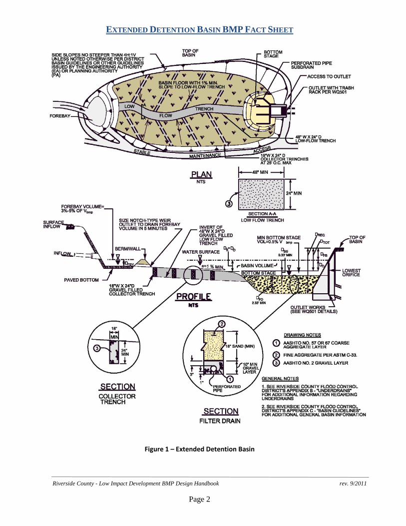
The Extended Detention Basin (EDB) is designed to detain the design volume of stormwater, VBMP, and maximize opportunities for volume losses through infiltration, evaporation, evapotranspiration and surface wetting. Additional pollutant removal is provided through sedimentation, in which pollutants can attach to sediment accumulated in the basin through the process of settling. Stormwater enters the EDB through a forebay where any trash, debris, and sediment accumulate for easy removal. Flows from the forebay enter the basin which is vegetated with native grasses that enhance infiltration and evapotranspiration, and which is interspersed with gravel-filled trenches that help further enhance infiltration. Water that does not get infiltrated or evapotranspired is conveyed to the bottom stage of the basin. At the bottom stage of the basin, low or incidental dry weather flows will be treated through a sand filter and collected in a subdrain structure. Any additional flows will be detained in the basin for an extended period by incorporating an outlet structure that is more restrictive than a traditional detention basin outlet. The restrictive outlet structure extends the drawdown time of the basin which further allows particles and associated pollutants to settle out before exiting the basin, while maximizing opportunities for additional incidental volume losses.
EXTENDED DETENTION BASIN BMP FACT SHEET
Riverside County - Low Impact Development BMP Design Handbook rev. 9/2011
Page 2
Figure 1 – Extended Detention Basin
EXTENDED DETENTION BASIN BMP FACT SHEET
Riverside County - Low Impact Development BMP Design Handbook rev. 9/2011
Page 3
Siting Considerations
Soils: EDBs can be used with almost all soils and geology. However, pollutant removal effectiveness is greatly improved when the underlying soil permits at least some infiltration.
Tributary Area: EDBs should only be used where the tributary drainage area is at least 5 acres, since meeting the draw-down requirements (discussed below) for smaller areas would result in very small outlet orifice diameters which would be prone to clogging.
Proximity to Receiving Waters: All site runoff must be treated to the MEP with appropriate BMPs before being discharged into Receiving Waters; as such the EDB cannot be constructed in-line within Receiving Waters.
Setbacks: Due to the infiltration characteristics incorporated into the EDB design, the lowest pervious point (beneath the filter drain) of the extended detention facility should be a minimum of 10' above the seasonal high groundwater table. All other setbacks shall be in accordance with applicable standards of the “Basin Guidelines” (Appendix C) or other guidelines issued by the Engineering Authority (EA).
Basin Guidelines: See Section 1 of the “Basin Guidelines” (Appendix C) for additional requirements (i.e., fencing, maintenance access, etc.) that may be required by the Engineering Authority (EA).
Landscaping Requirements
Basin vegetation provides erosion protection, enhances evapotranspiration and infiltration, and improves pollutant removal. The upper stage basin surface, berms and side slopes shall be planted with native grasses. Proper landscape management is also required to ensure that the vegetation does not contribute to water pollution through the use of pesticides, herbicides, or fertilizers. Landscaping shall be in accordance with applicable standards of the “Basin Guidelines” (Appendix C) or other guidelines issued by the EA.
EXTENDED DETENTION BASIN BMP FACT SHEET
Riverside County - Low Impact Development BMP Design Handbook rev. 9/2011
Page 4
Maintenance Guidelines Schedule Inspection and Maintenance Activity
During every scheduled maintenance check (per below), and as needed at other times
• Maintain vegetation as needed. Use of fertilizers, pesticides and herbicides should be strongly avoided to ensure they don’t contribute to water pollution. If appropriate native plant selections and other IPM methods are used, such products shouldn’t be needed. If such projects are used:
o Care should be taken to avoid contact with the low-flow or other trenches, and the media filter in the bottom stage.
o Products shall be applied in accordance with their labeling, especially in relation to application to water, and in areas subjected to flooding.
o Fertilizers should not be applied within 15 days before, after, or during the rainy season.
• No ponded water should be present for more than 72 hours to avoid nuisance or vector problems. No algae formation should be visible. Correct problems as needed.
Annually. If possible, schedule these inspections before the beginning of the rain season to allow for any repairs to occur before rains occur.
• Remove debris and litter from the entire basin • Inspect hydraulic and structural facilities. Examine the outlet for
clogging, the embankment and spillway integrity, as well as damage to any structural element.
• Check for erosion, slumping and overgrowth. Repair as needed. • Inspect sand media at the filter drain to verify it is allowing acceptable
infiltration. Scarify top 3 inches by raking the filter drain’s sand surface annually.
• Check the media filter underdrains (via the cleanout) for damage or clogging. Repair as needed.
• Remove accumulated sediment and debris from the forebay, and ensure that the notch weir is clear and will allow proper drainage.
• Check gravel filled low flow and collector trenches for sediment buildup and repair as needed.
Every 5 years or sooner (depending on whether observed drain times to empty the basin are less than 72 hours).
• Remove the top 3 inches of sand from the filter drain and backfill with 3 inches of new sand to return the sand layer to its original depth. When scarification or removal of the top 3 inches of sand is no longer effective, remove and replace sand filter layer.
Whenever substantial sediment accumulation has occurred.
• Remove accumulated sediment from the bottom of the basin. Removal should extend to original basin depth.
EXTENDED DETENTION BASIN BMP FACT SHEET
Riverside County - Low Impact Development BMP Design Handbook rev. 9/2011
Page 5
Design Summary
Note: The information contained in this BMP Factsheet is intended to be a summary of design considerations and requirements. Additional information which applies to all detention basins may be found in the “Basin Guidelines” (Appendix C). In addition, information herein may be superseded by other guidelines issued by the Engineering Authority.
Design Procedure These steps correspond to and provide a description of the information required in the EDB Design Worksheet.
1. Find the Design Volume, VBMP. a) Enter the tributary area, AT to the BMP. The minimum tributary area is 5 acres.
b) Enter the Design Volume, VBMP, determined from Section 2.1 of this Handbook.
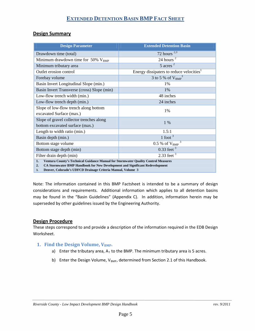
Design Parameter Extended Detention Basin
Drawdown time (total) 72 hours 2,3 Minimum drawdown time for 50% VBMP 24 hours 2 Minimum tributary area 5 acres 2
Outlet erosion control Energy dissipaters to reduce velocities1
Forebay volume 3 to 5 % of VBMP3
Basin Invert Longitudinal Slope (min.) 1% Basin Invert Transverse (cross) Slope (min) 1% Low-flow trench width (min.) 48 inches Low-flow trench depth (min.) 24 inches Slope of low-flow trench along bottom excavated Surface (max.)
1%
Slope of gravel collector trenches along bottom excavated surface (max.)
1 %
Length to width ratio (min.) 1.5:1 Basin depth (min.) 1 foot 3 Bottom stage volume 0.5 % of VBMP 3 Bottom stage depth (min) 0.33 feet 3 Filter drain depth (min) 2.33 feet 3 1. Ventura County’s Technical Guidance Manual for Stormwater Quality Control Measures 2. CA Stormwater BMP Handbook for New Development and Significant Redevelopment 3. Denver, Colorado’s UDFCD Drainage Criteria Manual, Volume 3
EXTENDED DETENTION BASIN BMP FACT SHEET
Riverside County - Low Impact Development BMP Design Handbook rev. 9/2011
Page 6
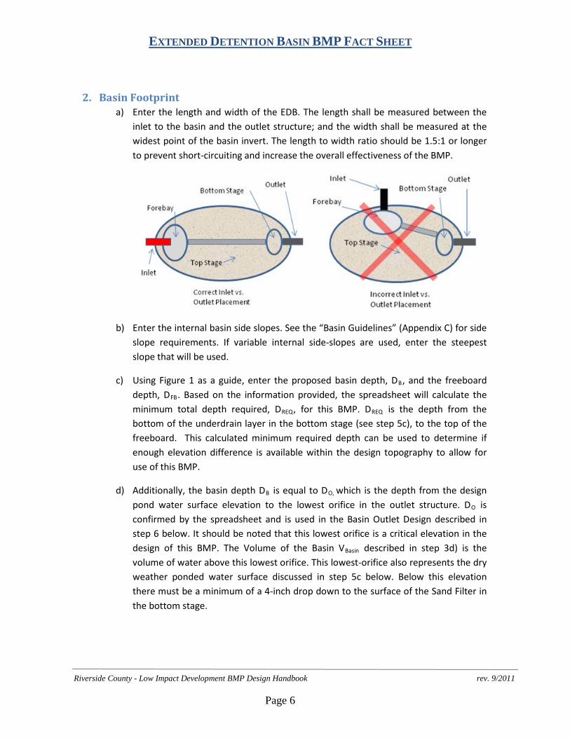
2. Basin Footprint a) Enter the length and width of the EDB. The length shall be measured between the
inlet to the basin and the outlet structure; and the width shall be measured at the widest point of the basin invert. The length to width ratio should be 1.5:1 or longer to prevent short-circuiting and increase the overall effectiveness of the BMP.
b) Enter the internal basin side slopes. See the “Basin Guidelines” (Appendix C) for side slope requirements. If variable internal side-slopes are used, enter the steepest slope that will be used.
c) Using Figure 1 as a guide, enter the proposed basin depth, DB, and the freeboard depth, DFB. Based on the information provided, the spreadsheet will calculate the minimum total depth required, DREQ, for this BMP. DREQ is the depth from the bottom of the underdrain layer in the bottom stage (see step 5c), to the top of the freeboard. This calculated minimum required depth can be used to determine if enough elevation difference is available within the design topography to allow for use of this BMP.
d) Additionally, the basin depth DB is equal to DO, which is the depth from the design pond water surface elevation to the lowest orifice in the outlet structure. DO is confirmed by the spreadsheet and is used in the Basin Outlet Design described in step 6 below. It should be noted that this lowest orifice is a critical elevation in the design of this BMP. The Volume of the Basin VBasin described in step 3d) is the volume of water above this lowest orifice. This lowest-orifice also represents the dry weather ponded water surface discussed in step 5c below. Below this elevation there must be a minimum of a 4-inch drop down to the surface of the Sand Filter in the bottom stage.
EXTENDED DETENTION BASIN BMP FACT SHEET
Riverside County - Low Impact Development BMP Design Handbook rev. 9/2011
Page 7
3. Basin Design a) The Total Basin Depth, DTOT, is calculated automatically, and is the sum of the basin
depth DB plus the freeboard depth DFB.
b) Enter the longitudinal slope of the basin invert. This slope must be at least 1% and is measured along the low flow trench between the forebay and the bottom stage. Note that the surface of the sand layer in the bottom stage must be level (see Figure 1).
c) Enter the transverse slope of the basin invert. This transverse (cross sectional) slope must be at least 1% sloped toward the low flow trench.
d) Enter the Volume of the Basin, VBasin. This volume must be the actual volume of water held within the basin as substantiated by modeling or appropriate volumetric calculations, and must be equal to or greater than VBMP. This volume must be held above the lowest orifice in the Basin Outlet Design described in step 6 below.
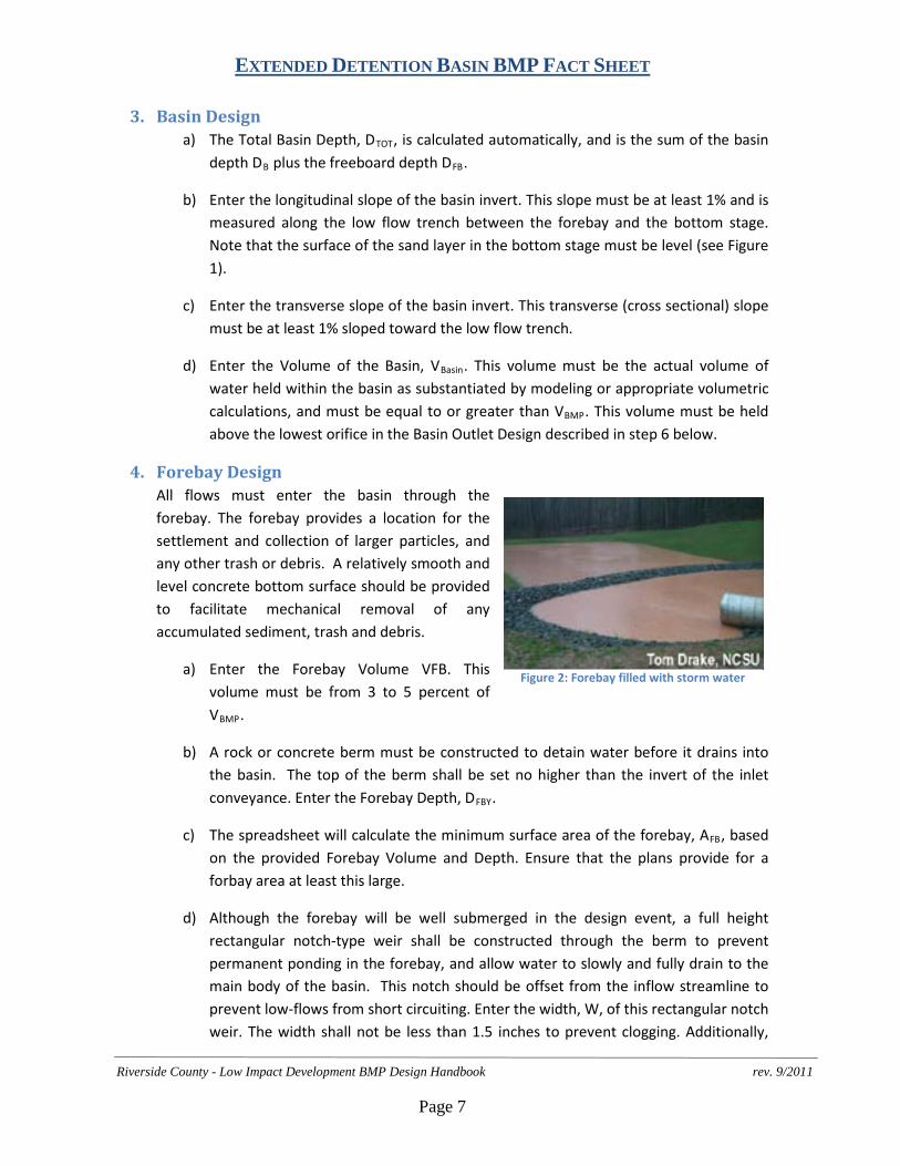
4. Forebay Design All flows must enter the basin through the forebay. The forebay provides a location for the settlement and collection of larger particles, and any other trash or debris. A relatively smooth and level concrete bottom surface should be provided to facilitate mechanical removal of any accumulated sediment, trash and debris.
a) Enter the Forebay Volume VFB. This volume must be from 3 to 5 percent of VBMP.
b) A rock or concrete berm must be constructed to detain water before it drains into the basin. The top of the berm shall be set no higher than the invert of the inlet conveyance. Enter the Forebay Depth, DFBY.
c) The spreadsheet will calculate the minimum surface area of the forebay, AFB, based on the provided Forebay Volume and Depth. Ensure that the plans provide for a forbay area at least this large.
d) Although the forebay will be well submerged in the design event, a full height rectangular notch-type weir shall be constructed through the berm to prevent permanent ponding in the forebay, and allow water to slowly and fully drain to the main body of the basin. This notch should be offset from the inflow streamline to prevent low-flows from short circuiting. Enter the width, W, of this rectangular notch weir. The width shall not be less than 1.5 inches to prevent clogging. Additionally,
Figure 2: Forebay filled with storm water
EXTENDED DETENTION BASIN BMP FACT SHEET
Riverside County - Low Impact Development BMP Design Handbook rev. 9/2011
Page 8
immediately outside the notch construct a minimum 1-foot by 1-foot gravel pad to prevent vegetative growth within the basin invert from blocking the notch.
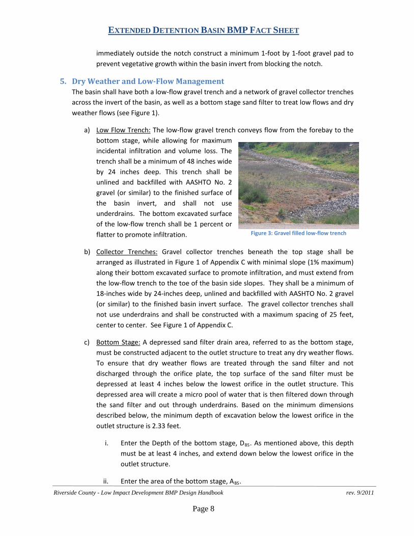
5. Dry Weather and Low-Flow Management The basin shall have both a low-flow gravel trench and a network of gravel collector trenches across the invert of the basin, as well as a bottom stage sand filter to treat low flows and dry weather flows (see Figure 1).
a) Low Flow Trench: The low-flow gravel trench conveys flow from the forebay to the bottom stage, while allowing for maximum incidental infiltration and volume loss. The trench shall be a minimum of 48 inches wide by 24 inches deep. This trench shall be unlined and backfilled with AASHTO No. 2 gravel (or similar) to the finished surface of the basin invert, and shall not use underdrains. The bottom excavated surface of the low-flow trench shall be 1 percent or flatter to promote infiltration.
b) Collector Trenches: Gravel collector trenches beneath the top stage shall be arranged as illustrated in Figure 1 of Appendix C with minimal slope (1% maximum) along their bottom excavated surface to promote infiltration, and must extend from the low-flow trench to the toe of the basin side slopes. They shall be a minimum of 18-inches wide by 24-inches deep, unlined and backfilled with AASHTO No. 2 gravel (or similar) to the finished basin invert surface. The gravel collector trenches shall not use underdrains and shall be constructed with a maximum spacing of 25 feet, center to center. See Figure 1 of Appendix C.
c) Bottom Stage: A depressed sand filter drain area, referred to as the bottom stage, must be constructed adjacent to the outlet structure to treat any dry weather flows. To ensure that dry weather flows are treated through the sand filter and not discharged through the orifice plate, the top surface of the sand filter must be depressed at least 4 inches below the lowest orifice in the outlet structure. This depressed area will create a micro pool of water that is then filtered down through the sand filter and out through underdrains. Based on the minimum dimensions described below, the minimum depth of excavation below the lowest orifice in the outlet structure is 2.33 feet.
i. Enter the Depth of the bottom stage, DBS. As mentioned above, this depth must be at least 4 inches, and extend down below the lowest orifice in the outlet structure.
ii. Enter the area of the bottom stage, ABS.
Figure 3: Gravel filled low-flow trench
EXTENDED DETENTION BASIN BMP FACT SHEET
Riverside County - Low Impact Development BMP Design Handbook rev. 9/2011
Page 9
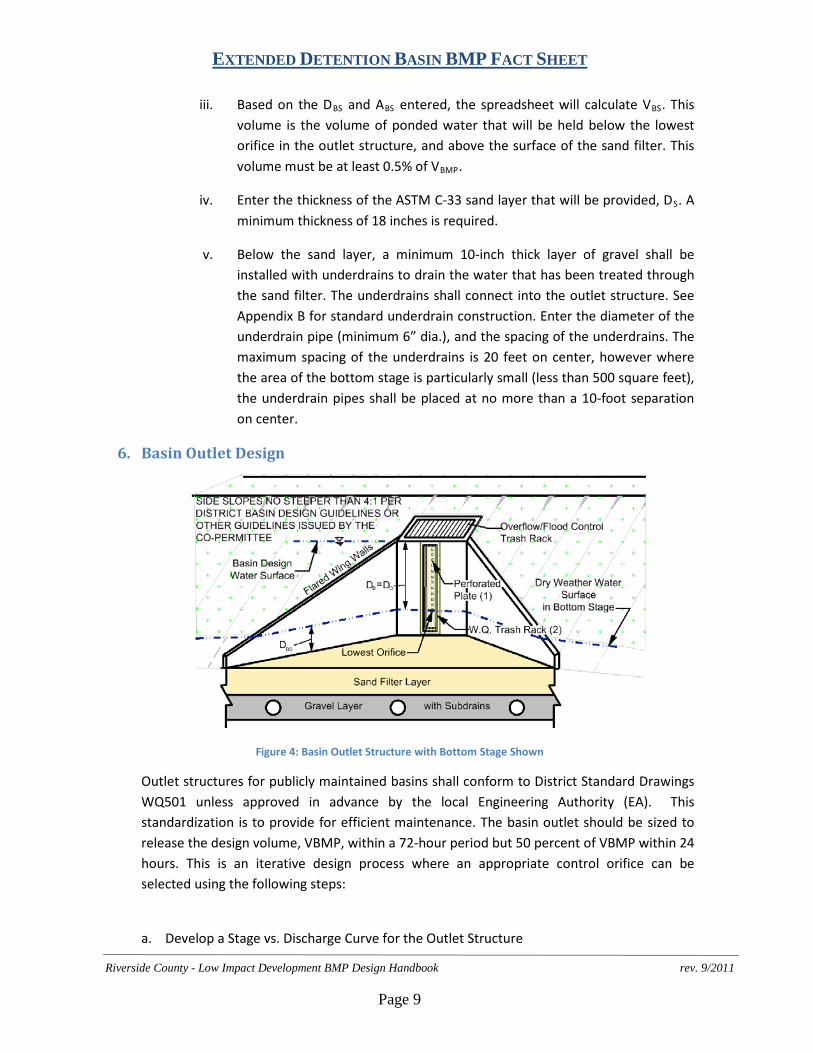
iii. Based on the DBS and ABS entered, the spreadsheet will calculate VBS. This volume is the volume of ponded water that will be held below the lowest orifice in the outlet structure, and above the surface of the sand filter. This volume must be at least 0.5% of VBMP.
iv. Enter the thickness of the ASTM C-33 sand layer that will be provided, DS. A minimum thickness of 18 inches is required.
v. Below the sand layer, a minimum 10-inch thick layer of gravel shall be installed with underdrains to drain the water that has been treated through the sand filter. The underdrains shall connect into the outlet structure. See Appendix B for standard underdrain construction. Enter the diameter of the underdrain pipe (minimum 6” dia.), and the spacing of the underdrains. The maximum spacing of the underdrains is 20 feet on center, however where the area of the bottom stage is particularly small (less than 500 square feet), the underdrain pipes shall be placed at no more than a 10-foot separation on center.
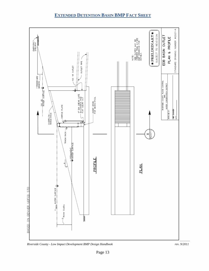
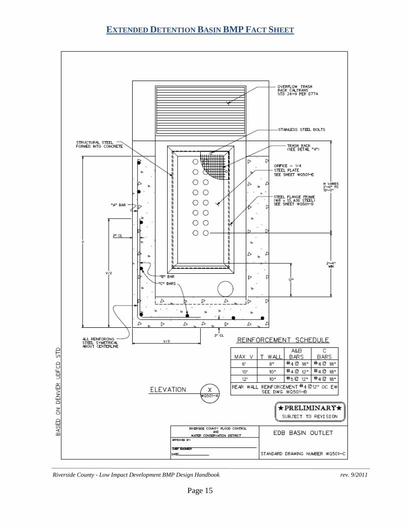
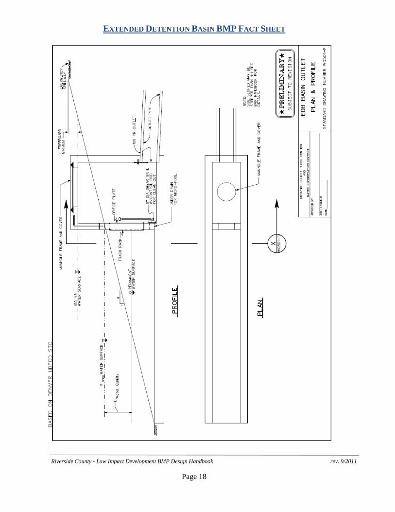
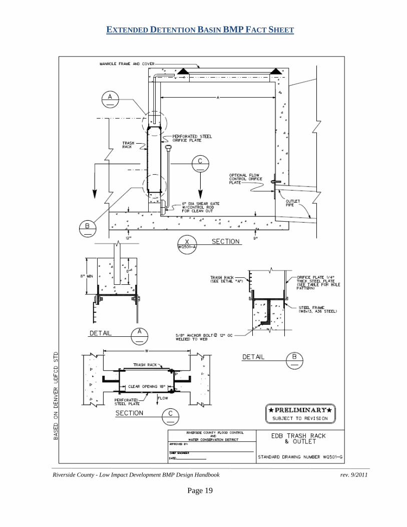
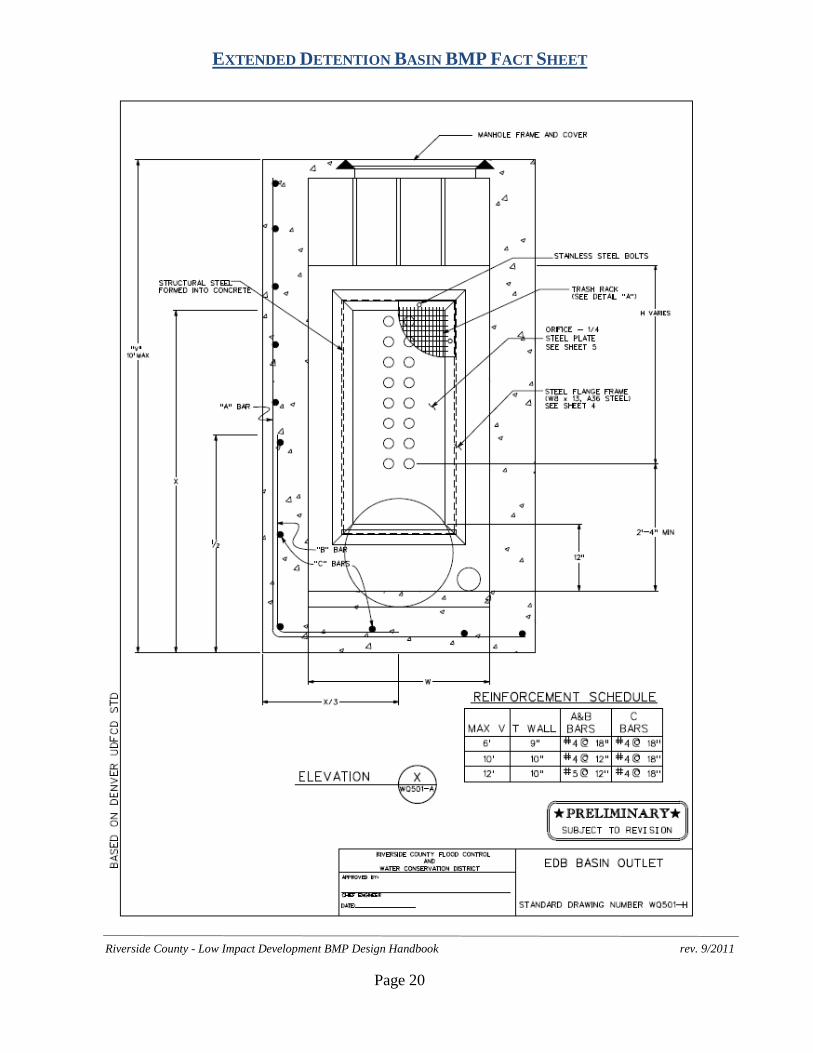
6. Basin Outlet Design
Figure 4: Basin Outlet Structure with Bottom Stage Shown
Outlet structures for publicly maintained basins shall conform to District Standard Drawings WQ501 unless approved in advance by the local Engineering Authority (EA). This standardization is to provide for efficient maintenance. The basin outlet should be sized to release the design volume, VBMP, within a 72-hour period but 50 percent of VBMP within 24 hours. This is an iterative design process where an appropriate control orifice can be selected using the following steps:
a. Develop a Stage vs. Discharge Curve for the Outlet Structure
EXTENDED DETENTION BASIN BMP FACT SHEET
Riverside County - Low Impact Development BMP Design Handbook rev. 9/2011
Page 10
Estimate the orifice size and outlet plate configuration (number per row, etc.). Based on DO provided in the Basin Footprint section, the spreadsheet will automatically generate the stage vs. discharge relationship for this outlet:
Q = C*A*[2*g*(H-Ho)]0.5
Where:
Q = discharge (ft3/s)
C = orifice coefficient
A = area of the orifice (ft)
g = gravitational constant (32.2 ft2/s)
H = water surface elevation (ft)
Ho = orifice elevation (ft)
The lowest orifice shall be located with its centerline at the top of the bottom stage; at least 4 inches above the surface of the sand filter drain. To help avoid clogging, the minimum orifice diameter is limited to 3/8 inch. Since the 1/4 inch thickness of the orifice plate will be less than the orifice diameter, a value for C of 0.66 may be used. If another value for C is used, justification may be required.
b. Develop a Discharge/Volume vs. Stage Table for the Basin
Based on the shape and size of the basin, develop a relationship between the stage and the volume of water in the basin. Since the orifice spacing is 4 inches on center for the standard orifice plate, the stage intervals must also be 4 inches. Enter the basin volume at each interval starting at the centerline of the lowest orifice.
c. Route the Design Volume through the Basin
The spreadsheet assumes that the Design Volume, VBMP, enters the basin instantaneously and as such, no inflow/outflow hydrograph is necessary. The drawdown time for each stage becomes:
∆t = Vi/Q
Where:
∆t = drawdown time for each stage
Vi = the volume at each stage
Q = the flow rate corresponding to the headwater elevation at each stage.
The spreadsheet automatically determines the drawdown time from the sum of the ∆t values for each stage. If the orifice size and plate configuration estimate meets the
EXTENDED DETENTION BASIN BMP FACT SHEET
Riverside County - Low Impact Development BMP Design Handbook rev. 9/2011
Page 11
hydraulic retention time requirements (50% of the volume empties in not less than 24 hours, 100% of the volume empties in no more than 72 hours), the outlet is correctly sized. If these requirements are not met, select a new orifice size or configuration and repeat the process starting at Step 6a.
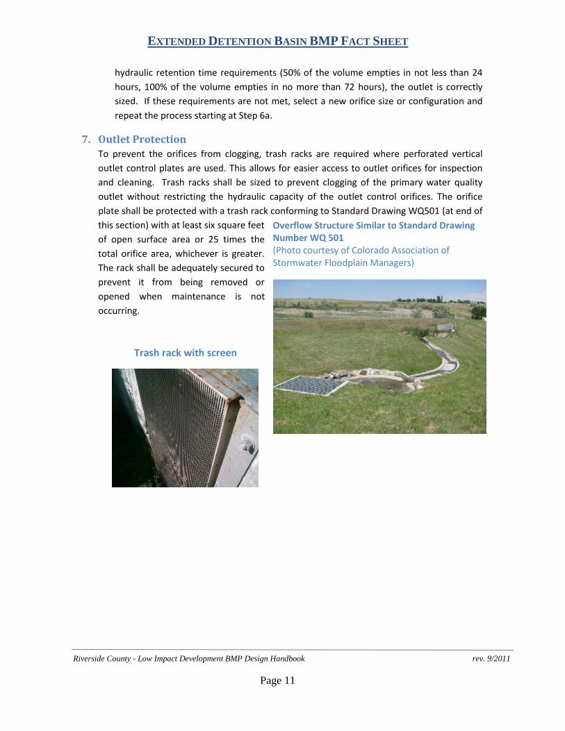
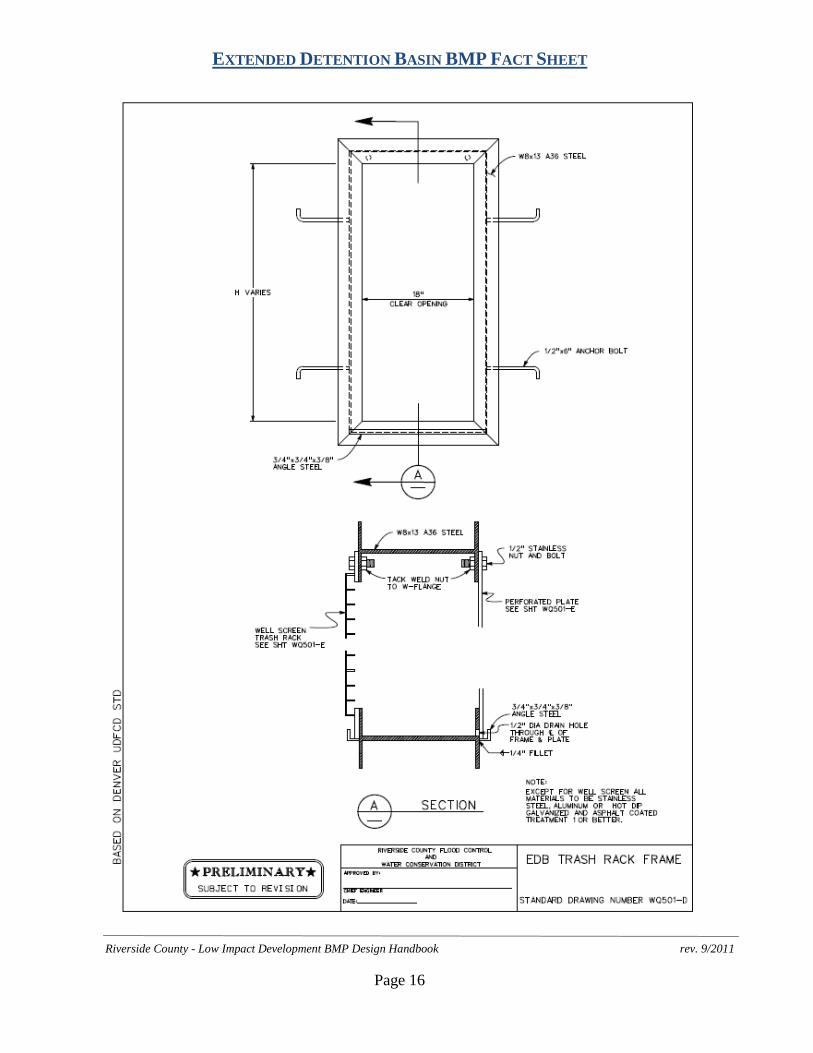
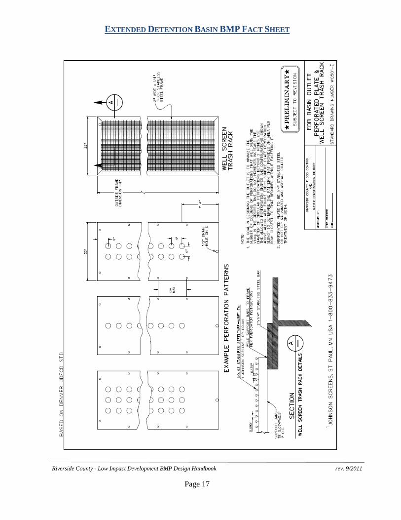
7. Outlet Protection To prevent the orifices from clogging, trash racks are required where perforated vertical
outlet control plates are used. This allows for easier access to outlet orifices for inspection and cleaning. Trash racks shall be sized to prevent clogging of the primary water quality outlet without restricting the hydraulic capacity of the outlet control orifices. The orifice plate shall be protected with a trash rack conforming to Standard Drawing WQ501 (at end of this section) with at least six square feet of open surface area or 25 times the total orifice area, whichever is greater. The rack shall be adequately secured to prevent it from being removed or opened when maintenance is not occurring.
Overflow Structure Similar to Standard Drawing Number WQ 501 (Photo courtesy of Colorado Association of Stormwater Floodplain Managers)
Trash rack with screen
EXTENDED DETENTION BASIN BMP FACT SHEET
Riverside County - Low Impact Development BMP Design Handbook rev. 9/2011
Page 12
8. Overflow Outlet Overflow outlets for publicly maintained basins shall conform to Standard Drawing WQ501 (at end of this section) unless approved in advance by the Engineering Authority (EA).
9. Embankment Embankments shall be designed in accordance with applicable standards of Riverside County Flood Control District’s “Basin Guidelines” (Appendix C) or other guidelines issued by the Engineering Authority (EA). Where applicable, embankment designs must additionally conform to the requirements of the State of California Division of Safety of Dams.
10. Spillway and Overflow Structures Spillway and overflow structures should be designed in accordance with applicable standards of the “Basin Guidelines” (Appendix C) or other guidelines issued by the Engineering Authority (EA).
EXTENDED DETENTION BASIN BMP FACT SHEET
Riverside County - Low Impact Development BMP Design Handbook rev. 9/2011
Page 13

EXTENDED DETENTION BASIN BMP FACT SHEET
Riverside County - Low Impact Development BMP Design Handbook rev. 9/2011
Page 14
EXTENDED DETENTION BASIN BMP FACT SHEET
Riverside County - Low Impact Development BMP Design Handbook rev. 9/2011
Page 15
EXTENDED DETENTION BASIN BMP FACT SHEET
Riverside County - Low Impact Development BMP Design Handbook rev. 9/2011
Page 16
EXTENDED DETENTION BASIN BMP FACT SHEET
Riverside County - Low Impact Development BMP Design Handbook rev. 9/2011
Page 17
EXTENDED DETENTION BASIN BMP FACT SHEET
Riverside County - Low Impact Development BMP Design Handbook rev. 9/2011
Page 18
EXTENDED DETENTION BASIN BMP FACT SHEET
Riverside County - Low Impact Development BMP Design Handbook rev. 9/2011
Page 19
EXTENDED DETENTION BASIN BMP FACT SHEET
Riverside County - Low Impact Development BMP Design Handbook rev. 9/2011
Page 20