3.7 groundwater - klamath restoration: home
TRANSCRIPT

Chapter 3 – Affected Environment/Environmental Consequences 3.7 Groundwater
3.7-1 – September 2011
3.7 Groundwater
This section of the Klamath Facilities Removal Environmental Impact Statement/
Environmental Impact Report (EIS/EIR) describes the changes in groundwater levels and
availability that would be caused by the Proposed Action and alternatives.
3.7.1 Area of Analysis
This EIS/EIR’s area of analysis, or “project area,” for groundwater as related to the
Klamath Hydroelectric Settlement Agreement (KHSA) includes the area within 2.5 miles
upstream of J.C. Boyle, Copco 1, Copco 2, and Iron Gate Reservoirs. The project area
lies within Klamath County, Oregon, and Siskiyou County, California. The project area
for the Klamath Basin Restoration Agreement (KBRA) with respect to groundwater is the
Klamath basin upstream of Copco 1 Dam. This is the area covered by a United States
Geological Survey (USGS)-Oregon Water Resources Department (WRD) groundwater
model designed to determine effects on groundwater from pumping water for irrigation
purposes. No model exists for areas below Copco 1 Dam. Groundwater issues, such as
changes in groundwater levels or recharge, are described in this section, 3.7
Groundwater. Issues related to geology are described in Section 3.11, Geology, Soils,
and Geologic Hazards.
3.7.2 Regulatory Framework
Groundwater resources within the area of analysis are regulated by the state and local
laws listed below.
3.7.2.1 State Authorities and Regulations
California Water Code (CWC §10750, §10753.7, §1702, §1706, §1727, §1736,
and §1810) (California, State of)
California Assembly Bill 3030 (CWC §10750 et seq.)
California Senate Bill 1938 (Sections 10753.4 and 10795.4 of, to amend and
renumber Sections 10753.7, 10753.8, and 10753.9 of, and to add Sections
10753.1 and 10753.7)
Oregon Revised Statutes (Chapters 536 through 541) (Oregon, State of)
California Department of Water Resources (DWR) Bulletin 118 (DWR 2003)
3.7.2.2 Local Authorities and Regulations
Siskiyou County Code (Title 3, Chapter 19) (Siskiyou County)
3.7.3 Existing Conditions/Affected Environment
3.7.3.1 Groundwater Basin Hydrology Description
Regional Groundwater Conditions
The project area has few wells that completely characterize groundwater conditions.
Gannett et al. 2010 completed the most recent and comprehensive attempt to estimate the

Klamath Facilities Removal EIS/EIR Public Draft
3.7-2 – September 2011
water level gradients and flow patterns within the project area upstream and downstream
of the four dam sites. Figures 3.7-1 and 3.7-2 show a generalized groundwater flow map
for the Upper Klamath Basin and portions of the Lower Klamath Basin. Figure 3.7-2
suggests that the regional groundwater flow patterns along the Klamath River
downstream of Keno Dam are generally from the higher elevations (upland areas,
mountain ranges, hills, etc.) toward the Klamath River, and from Keno Dam toward Iron
Gate Dam (United States Department of the Interior [DOI] 2011a). Figure 3.7-2 suggests
a groundwater divide exists under Keno Dam. The groundwater level contours suggest
that the groundwater system above Keno Dam is isolated from the groundwater system
below Keno Dam.
The Lead Agencies reviewed the area around the reservoirs on USGS topographic
7½-minute quadrangle maps (Iron Gate and Copco Quadrangles in California; Spencer
Creek and Chicken Hills Quadrangles in Oregon) (DOI 2011a). Numerous springs,
where groundwater discharges to the surface, are shown surrounding Iron Gate Reservoir.
These springs occur at elevations from less than 50 to more than 300 feet (ft) above the
reservoir level (DOI 2011a). The maps also show springs around Copco Reservoir.
These springs are similarly less than 50 to more than 800 feet above the reservoir level
(DOI 2011a).
The USGS mapping shows a number of the small drainages that empty into Copco
Reservoir have a spring at the headwater of the drainage. The maps show very few
springs in the vicinity of J.C. Boyle Reservoir, and those that are shown are only a few
tens of feet above the reservoir level (DOI 2011a). However, many of the small
drainages that empty into J.C. Boyle Reservoir have a spring at the headwater of the
drainage (e.g., Spencer Creek (Gannett et al. 2010)). The presence of springs in the area
suggests local groundwater systems, and possibly a regional groundwater system, that are
not receiving water directly from the reservoirs (DOI 2011a). That is, the water
discharging from the springs is not thought to be reservoir water (DOI 2011a).
The flows from the springs and the location of the springs could be influenced indirectly
by the presence of a reservoir because the reservoir could create higher groundwater
levels adjacent to the reservoir. These higher groundwater levels could cause
groundwater levels to be increased as compared to the condition where the reservoir was
not in place. These increased groundwater levels could rise to the ground surface and
affect the location of a spring and the volume of water discharging from the spring. The
level of hydraulic connection between the reservoirs and the spring systems is not known
(DOI 2011a).
A spring complex about one mile below J.C. Boyle Dam contributes substantial flow to
the river (Gannett et al. 2010). The water discharging at this site may be originating from
the local groundwater system. The flows could also be influenced by seepage from the
reservoir that is flowing around or under the dam and coming to the surface at the spring
site. It is likely that the flows from this spring complex are influenced by both the local
groundwater system as well as leakage from the reservoir (DOI 2011a).

Chapter 3 – Affected Environment/Environmental Consequences 3.7 Groundwater
3.7-3 – September 2011
Figure 3.7-1. Generalized Groundwater Potentiometric Surface Contour Map and Groundwater Flow Directions in the Upper
Klamath Basin [after Gannett et al. 2010]

Klamath Facilities Removal EIS/EIR Public Draft
3.7-4 – September 2011
Figure 3.7-2. Enlarged Portion of the Generalized Groundwater Potentiometric Surface Contour Map and Flow Directions for the Areas Around J.C. Boyle, Copco, and Iron Gate Reservoirs [after
Gannett et al. 2010]

Chapter 3 – Affected Environment/Environmental Consequences 3.7 Groundwater
3.7-5 – September 2011
Sources of Groundwater in Project Area
Groundwater in the project area is likely fed by the infiltration and subsequent
percolation of precipitation through the surface materials to the bedrock units. As
Figures 3.7-1 and 3.7-2 show, at a regional scale, groundwater appears to flow into the
project area near the four dams from upland areas toward the Klamath River and the
reservoirs. The figures show an apparent groundwater divide in the area just upstream of
J.C. Boyle/Keno Impoundment. These figures also show the regional trends in
groundwater elevations and flow paths. Where groundwater levels are above the river
and reservoir elevations, it is generally assumed that groundwater levels in the vicinity of
the reservoirs are supported by the regional groundwater system more so than by
reservoir leakage. However wells immediately adjacent (potentially extending up to a
mile from the reservoirs under certain conditions) to the reservoirs are more likely
influenced by reservoir leakage where such leakage exists.
Local groundwater in the project area is also fed by groundwater underflow from these
upgradient areas. In the absence of barriers to vertical flow, surface water infiltration is a
common source of recharge to groundwater systems. Rivers, lakes and other surface
water bodies are common sources of site specific infiltration recharge. Aerial
precipitation is more of a dispersed, wide extent source of infiltration recharge. Given a
regional groundwater flow direction toward the river and reservoirs in the project area,
reaches are more likely receiving water from the groundwater systems than they are
losing water to the groundwater systems, while reservoirs are more likely to lose water to
the groundwater (DOI 2011a). However, there are conditions where the reservoirs could
be gaining water from the groundwater system(s) (DOI 2011a). The lack of data from
groundwater wells in the area makes a more specific characterization of groundwater
sources in the project area difficult.
Groundwater Sinks in Project Area
In areas where surface water levels are lower than the adjacent groundwater level,
groundwater can discharge to the surface water (e.g., rivers, streams, and reservoirs). This
would be called a groundwater “sink” because groundwater flows towards it and is lost
from the groundwater system. Gannett et al. (2010) estimates that groundwater adjacent
to the Klamath River discharges to the river in the project area. An average discharge of
190 cfs of groundwater for the reach from Keno Dam to downstream of the J.C. Boyle
Powerhouse and 92 cfs for the reach from there downstream to Iron Gate Dam is
estimated (Gannett et al. 2010). These estimates are calculated for the length of each of
these reaches based on gage data and changes in reservoir storage. These estimates may
include some ungaged tributary inflows.
Groundwater pumping is also a typical process in the project area where water is
removed from the groundwater system. In the project area, groundwater is pumped to the
surface for domestic use and irrigation. Most domestic wells around the reservoirs are
likely seasonal residences (i.e., owner’s official address is different than the well location
address) and are not expected to be a major groundwater sink in the project area (DOI
2011a). Average well yields in Siskiyou County, California are just over 19 gpm while
in Klamath County, Oregon the average yield is just over 22 gpm (DOI 2011a). Based on

Klamath Facilities Removal EIS/EIR Public Draft
3.7-6 – September 2011
completion dates on well logs for Siskiyou County, an average of five new wells per year
have been installed in the project area since 1963. In Klamath County the average is
about three new wells per year since 1976, including the area around Keno and Keno
Dam, Oregon (DOI 2011a).
A large groundwater flow system exists in the Upper Klamath Basin (Gannett et al.
2010). Groundwater is recharged in areas in the Cascade Range and upland areas
surrounding the basin. Groundwater flows from these areas toward the interior of the
basin and subbasins (Figure 3.7-1). Many of the streams in the interior of the basin are at
least partially fed by groundwater discharge (Gannett et al. 2010). Some streams are fed
predominately by groundwater (i.e., baseflow) at a consistent rate throughout the year.
Groundwater is used in the Upper Basin to irrigate agricultural land as well as for
domestic, industrial, and municipal purposes. Groundwater is used as a primary source of
irrigation water where surface water is not available and also as a supplemental source
when surface supplies are limited (Gannett et al. 2010).
Groundwater levels vary in response to both climatic and pumping conditions. Climatic
variations can vary the groundwater level by five feet within the basin. The typical
drawdown and recovery cycles caused by groundwater pumping can be from one to ten
feet. Groundwater use in the Upper Basin has increased by 50 percent since 2001
primarily in the area surrounding Reclamation’s Klamath Project. The increase in
pumping has resulted in groundwater levels dropping 10 to 15 feet in portions of this area
between 2001 and 2004 (Gannett et al. 2010).
Local Groundwater Conditions
The California DWR Bulletin 118 – Update 2003, California’s Groundwater, delineates
515 groundwater basins and subbasins throughout the state. The area of analysis for the
Proposed Action and alternatives does not fall within one of these delineated basins. The
area is defined as a “groundwater source area” by the California DWR. A “groundwater
source area” is “rocks that are significant in terms of being a local groundwater sources,
but do not fit the [typical] category of basin or subbasin” (DWR 2003). The Klamath
River from the Oregon-California Stateline to downstream from Iron Gate Dam is a
predominantly non-alluvial river flowing through mountainous terrain. Downstream
from the Iron Gate Dam, and for most of the river’s length to the Pacific Ocean, the river
maintains a relatively steep, high-energy, coarse-grained channel frequently confined by
bedrock. Section 3.11, Geology, Soils, and Geologic Hazards, of this document describes
project area geology in more detail.
Well information was obtained and reviewed from the databases of both the Oregon
WRD and the California DWR to identify well logs for known domestic and irrigation
wells within several miles upstream and downstream of the Four Facilities. Roughly
83 percent of the logs (300 out of 360 logs) had sufficient information to be able to
identify with a reasonable amount of certainty the locations of these wells in relation to
the reservoirs. Of the 300 logs for which reasonable coordinate data could be

Chapter 3 – Affected Environment/Environmental Consequences 3.7 Groundwater
3.7-7 – September 2011
determined, only 63 wells were within 2.5 miles of one or more of the three reservoirs,
25 near Iron Gate, 22 near Copco 1 and 2, and 16 near J.C. Boyle (DOI 2011a).
Using the local topography, reservoir bathymetry, and lithologic descriptions on the well
logs, representative cross-sections across various spans of the reservoirs were generated
such that each cross-section intersected at least one known well location. The cross-
section for J.C. Boyle is presented below, and cross sections for Copco 1 and 2 and Iron
Gate are presented in Appendix K. Each cross-section displays the topography, water
surface elevation of the reservoir, well log ID, abbreviated well log lithology, and the
static water level in the well. The water-bearing units in each well are presented in
summary tables for each reservoir.
The discussions of potential or possible impacts to the local wells from the Proposed
Action are predicated on the concept that in order to be impacted, the water-bearing unit
that each well is tapping must be hydraulically connected to the reservoir – either by
having the water-bearing unit exposed to the surface (i.e., daylight) within the reservoir
walls or being hydraulically connected to the reservoir through a series of permeable
layers between the reservoir and the water-bearing unit.
The potential for impacts to the wells is further predicated on the relative elevation
differences between the static water level in the well(s) and the water surface elevation of
the reservoir. Specifically, if the water-bearing unit being tapped by any given well is in
hydraulic connection with a reservoir, then the static water level in the well should be
similar or close to the water surface elevation in the reservoir. If the static water level is
higher or lower than the reservoir level, and the water-bearing unit is not exposed along
the reservoir walls, then it is likely that the water-bearing unit is reflecting a regional or
local aquifer system influence in addition to, or in place of, the reservoir. If the water-
bearing unit itself is entirely above the reservoir water levels, or is substantially deeper
(more than three or four intervening impermeable units) than the lowest portion of the
reservoir, then it would be unlikely that the water-bearing unit would be in hydraulic
connection with the reservoir. It should be noted that the static water level in a well can
vary from year to year based on preceding hydrologic conditions (i.e., climatic cycles,
wet years vs. dry years).
J.C. Boyle Reservoir
The bedrock surrounding and underlying the J.C. Boyle Reservoir is principally
composed of moderately well bedded to massive, moderately well-consolidated volcanic
rocks of the High Cascade Geomorphic Province. Lava flows dominate the landscape
and geologic strata and form many of the ridges above the reservoir. In the downstream
portion of the reservoir (downstream from the Highway 66 bridge) young lava flows line
the sides of the reservoir (DOI 2011a). Section 3.11, Geology, Soils, and Geologic
Hazards, provides additional geologic information.
The Oregon WRD well database identifies 50 wells within 2.5 miles of the J.C. Boyle
Reservoir (Oregon WRD 2011). Sixteen of these 50 wells were able to be located
geographically based on well addresses recorded on the drill logs or by comparing the
Klamath Facilities Removal EIS/EIR Public Draft
3.7-8 – September 2011
well log information to ownership parcel data supplied by Klamath County. Ten of those
16 wells were shallow Oregon Department of Transportation borings near bridge
footings. Figure 3.7-3 shows the locations of the wells that could be located. The
construction details for these wells are outlined in Appendix K.
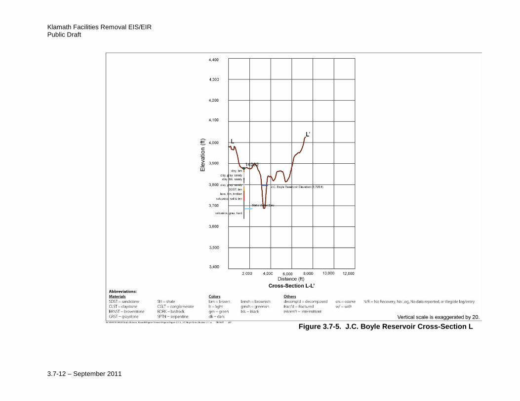
Three cross-sections that intersected at least one of the six wells were developed. Figure
3.7-3 shows the locations of these cross-sections. Figures 3.7-4 and 3.7-5 show the cross-
sections. The well parameters used to develop the cross-sections are summarized in
Table 3.7-1.
The data in Table 3.7-1 suggests that the water-bearing volcanic units of the High
Cascade are deeper than the bottom elevation of the reservoir (i.e., the pre-reservoir river
bed) in wells 10059 and 51633. The static water level for each well is 50 to 100 ft below
the bottom of the reservoir. The top of the water bearing layer and the static water level in
well 14002 are similar to the elevation of the river bed (DOI 2011a). Therefore, the
reservoir level is unlikely to affect these wells.
The lateral extent, homogeneity/inhomogeneity, and degree of fracturing, of the volcanic
deposits in the region are variable. Some degree of hydraulic connectivity exists between
the reservoir and water bearing strata near the reservoir which allows downward
migration of reservoir water. There may also be a zone of similar horizontal hydraulic
connectivity around the reservoir. The extent and degree of connectivity is uncertain
based on the limited well data. Both wells 10059 and 14002 have significant amounts of
clay recorded on the logs at depths between the top of their water bearing units and the
equivalent depth of the old river bed that probably inhibits or significantly reduces the
vertical migration of infiltration water from the reservoir. The extents of these clay units
are uncertain (DOI 2011a).
Comparison of the elevations of the static water levels in the six wells near J.C. Boyle
reservoir shows that two wells downstream of the dam (13628, 14002) have static water
levels 20 to 40 feet below the pre-dam river bed elevation (at the dam site); the two wells
(10514, 10059) furthest away from the reservoir (4,721 feet and 5,518 feet from the
reservoir) have static water level elevations nearly 100 feet below the pre-dam upstream
river bed elevation; and the two wells near the shore of the reservoir have static water
level elevations 20 to 30 feet below the pre-dam river bed elevation at the dam site. The
static water level elevations in the wells furthest from the reservoir are near or below the
static water level elevations for the wells closer to the reservoir. No clear determination
of any trends in vertical head gradients can be drawn from the data of these six wells
(DOI 2011a).

Chapter 3 – Affected Environment/Environmental Consequences 3.7 Groundwater
3.7-9 – September 2011
Figure 3.7-3. Locatable Wells within 2.5 Miles of J.C. Boyle Reservoir and Cross-Section Locations

Klamath Facilities Removal EIS/EIR Public Draft
3.7-10 – September 2011
Table 3.7-1. Well Construction Information for Wells1 within 2.5 Miles of J.C. Boyle Reservoir2
Well ID3 Drill Date
Well Diameter
(in)
Depth to top of perforated
zone or bottom of surface
casing in an open well (ft)
Depth to bottom of perforated zone (ft)
Depth of
Well (ft)
Depth to 1st Water
(ft)
Pumping Rate
(gpm)
Depth to
Static Water
(ft)
Located on
Cross-Section
Static Water
Elevation (ft)
Water-Bearing Unit and Top Elevation
(ft)
10059 6/29/1990 6 159 4 Open 281 77 12 222 J 3,686
Brown lava and clay from 203 to 223 ft bgs interspersed with black rock from 212 to 215 ft bgs, and gray rock and
clay, and gray rock from 223 to 281 ft bgs with bubbly brown lava from 257 to 280 ft bgs;
Elevation 3,705 ft
14002 8/10/1988 6 99 4 Open 238 181 25 178 L 3,698
Hard gray volcanic rock from 181 to 238 ft bgs; Elevation 3,695 ft
51633 10/19/2006 6 280 4 Open 315 126 55 126 K 3,701
Gray and brown basalt from 126 to 315 ft bgs interspersed with hard
gray baslalt, broken and fractured zones, and two ash layers; Elevation 3,700 ft
Source: DOI 2011a, DOI 2010. Notes: 1Well list does not include Oregon Department of Transportation boreholes used for bridge footings.
2Reservoir stage is 3,787 ft AMSL; river bed elevation at the dam is 3,720 ft AMSL.
3All wells listed as domestic supply wells.
4Depth to the bottom of the surface casing or sanitary seal in holes/wells that are openKey:
Key: AMSL: above mean sea level bgs: below ground surface in: inches ft: feet gpm: gallons per minute

Chapter 3 – Affected Environment/Environmental Consequences 3.7 Groundwater
3.7-11 – September 2011
Figure 3.7-4. J.C. Boyle Reservoir Cross-Sections J and K
Klamath Facilities Removal EIS/EIR Public Draft
3.7-12 – September 2011
Figure 3.7-5. J.C. Boyle Reservoir Cross-Section L

Chapter 3 – Affected Environment/Environmental Consequences 3.7 Groundwater
3.7-13 – September 2011
Copco 1 and Copco 2 Reservoirs
As described in Section 3.11, Geology, Soils, and Geologic Hazards, Copco Lake
including the smaller impoundment at Copco 2 Dam, sits at the divide between the
Western Cascade and the High Cascade geomorphic provinces. The Western Cascade is
faulted and intruded by basaltic dikes and its composition of lower and higher permeable
stratified rocks results in discrete aquifer units. The relationship between groundwater
flow in and between the High Cascade and Western Cascade is complicated and not well
understood but the groundwater utilized in the vicinity of Copco Lake is likely contained
in the permeable units of the High Cascade or upper water bearing units of the eastern
dipping Western Cascade based upon the generally shallow depth of known groundwater
wells. The Western Cascade strata have the potential to contain geothermal reservoirs
where capped by the High Cascade lava flows (Hammond 1983).
The identification of wells in the vicinity of the Copco Reservoirs followed the same
method as for the J.C. Boyle Reservoir. The California DWR well database identifies 22
wells within 2.5 miles of the Copco Reservoirs. Figures and tables showing the locations
and construction details of the 22 identified wells and the five cross-sections that were
developed are provided in Appendix K.
The data for the wells in the cross-sections indicate that the water-bearing units and static
water levels are above the bottom of the reservoir. All the wells near the Copco
Reservoirs, with the exception of one well, have static water levels that are below the
reservoir stage but above the river bed elevation at the dam site. Similarly, all the wells
except one have elevations for the top of the water bearing unit below the reservoir stage
and above the river bed elevation at the dam site. The two exceptions are two different
wells. The top of the water bearing formation was not identified on the log for some
wells. In this case, the elevation at which water was first encountered in the drilling is
used as a substitute for the top of the water bearing unit.
The average static water level for all wells less than 300 feet from the reservoir is 2,591
feet while the average static water level for all wells greater than 400 feet from the
reservoir is 2,680 feet (DOI 2011a). These levels suggest that there is downward
groundwater flow near the reservoir (i.e., groundwater is flowing down toward the
reservoir). Because groundwater is flowing toward the reservoir, this information
suggests that the water level in the reservoir does not have a significant lateral influence
on groundwater levels in the area around J.C. Boyle reservoir (DOI 2011a).
Iron Gate Reservoir
Iron Gate Reservoir overlies the volcanic units of the Western Cascade which like Copco
1 Reservoir have been faulted and intruded by basaltic dikes (Hammond 1983). The
relationship between groundwater flow in the units of the Western Cascade is
complicated and not well understood. Specific groundwater well data provides the best
understanding of the occurrence of groundwater in the vicinity of Iron Gate Reservoir.

Klamath Facilities Removal EIS/EIR Public Draft
3.7-14 – September 2011
The identification of wells in the vicinity of Iron Gate Reservoir followed the same
method as for the J.C. Boyle, Copco 1, and Copco 2 Reservoirs. The California DWR
well database identifies 25 wells within 2.5 miles of the Iron Gate Reservoir. Figures and
tables showing the locations and construction details of the 25 identified wells and the
five cross-sections that were developed are provided in Appendix K.
The well data shows that the static water level (when recorded) is above the reservoir
stage with only two exceptions (wells 781723, 99834). The static water level for all the
wells is also above the elevation of the river bed at the dam site with only one exception
(781723). The data in Appendix K shows that the estimated elevation of the top of the
water bearing unit (recorded on 13 of the 25 logs) is above the reservoir stage in 10 of the
13 wells. The top of the water bearing unit is between the reservoir stage and the
reservoir bottom in two wells. The top of the water bearing unit is below the reservoir
bottom in only one well (781723).
Wells further away from Iron Gate Reservoir have higher static water levels and
generally higher top of water bearing unit elevations than wells closer to the reservoir.
These elevations indicate groundwater flow direction is towards the reservoir in
agreement with the regional groundwater gradients (Gannett et al, 2010). Wells within
2,000 feet of the reservoir have static water levels very close or above to the reservoir
stage (one exception, well 334387) indicating a potential flow direction toward the
reservoir. The current well dataset cannot determine conclusively whether Iron Gate
Reservoir has any vertically downward or horizontal seepage (DOI 2011a).
3.7.4 Environmental Consequences
The section analyzes the environmental consequences on groundwater from
implementation of the Proposed Action or its alternatives. Effects to groundwater quality
are not expected because groundwater discharges to surface water in the majority of the
area. Impacts to water quality are discussed in detail in Section 3.2, Water Quality.
3.7.4.1 Environmental Effects Determination Methodology
The method for this analysis was to compare the effects of the Proposed Action and
alternatives to the existing conditions. This analysis used the groundwater information
presented in Section 3.7.3 to evaluate potential effects on existing wells and on
groundwater’s influence on surface water resources in the project area.
3.7.4.2 Significance Criteria
For the purposes of this EIS/EIR, impacts would be significant if they would result in the
following:
Lowering of the local groundwater table level so the production rate of pre-
existing nearby wells would drop to a level that would not support existing land
uses or planned uses for which permits have been granted.
Chapter 3 – Affected Environment/Environmental Consequences 3.7 Groundwater
3.7-15 – September 2011
Substantially interfering with groundwater levels or groundwater recharge so
there would be changes to the groundwater/surface water interaction that would
adversely affect surface water conditions or related resources.
Land subsidence caused by aquifer collapse can be caused by many processes such as the
dewatering of fine grained materials (i.e., clays) or collapse of the structure of an aquifer
(i.e., through dissolution or piping). Although land subsidence as a result of changes in
groundwater levels is a common significance criterion, it is not considered in this
EIS/EIR given that land subsidence would not be an effect of the Proposed Action or
alternatives because water levels would not be lowered in areas of substantial clay
deposits and the rock types of the aquifer are not susceptible to collapse in the area of
analysis.
3.7.4.3 Effects Determinations
Alternative 1: No Action/No Project
Under the No Action/No Project Alternative, there would be no change in project dam
and associated facility operations and no impacts on groundwater resources. Under the
No Action/No Project Alternative, J. C. Boyle, Copco 1, Copco 2, and Iron Gate Dams
and their associated facilities would remain in place and be operated similarly as they
have been during historical operations. Therefore, the No Action/No Project Alternative
would not change the elevation of surface water in the reservoirs outside of historical
ranges. Groundwater levels would be expected to remain consistent with historic values.
Therefore, no changes from existing conditions relative to the elevation of the
groundwater table in the vicinity of the reservoirs would be expected.
Under the No Action/No Project Alternative, there could be increased groundwater
storage. Activities associated with the No Action/No Project Alternative include certain
resource management actions that are currently approved and ongoing, and which would
continue to be implemented. Actions that could affect groundwater resources include
Agency Lake and Barnes Ranches. These actions would provide new storage to store
additional surface water supplies. In some years, when water is available, groundwater
use could decrease. Stored surface water would also increase seepage into underlying
groundwater basins. This would be a beneficial effect to groundwater resources.
Alternative 2: Full Facilities Removal of Four Dams (the Proposed Action)
Under the Proposed Action, groundwater levels in existing wells adjacent to the
reservoirs could decline in response to the drop in surface water elevation when the
reservoirs are removed. The water-bearing units from which most of the existing
domestic or irrigation wells pumps are either below the elevation of the original river
channel, are exposed along reservoir walls, or are above the reservoir stage. There is
limited data to fully characterize the degree of hydraulic connection between these water
bearing units and the reservoirs.
Some of the water-bearing units that are tapped by existing domestic or irrigation wells
are above the reservoir elevation and are at elevations similar to those of mapped springs.
These springs are likely fed by the same water-bearing units supplying the wells and

Klamath Facilities Removal EIS/EIR Public Draft
3.7-16 – September 2011
neither would likely be significantly impacted by the removal of the reservoirs. The
primary impact that would be expected could be a drop in the groundwater levels in these
higher elevation water bearing units as the reservoirs drain and new local groundwater
levels are established relative to the river elevation.
A number of existing domestic or irrigation wells lie close to the reservoir shorelines
(well within the 2.5 miles.) These wells may be influenced by the dropping reservoir
water levels when directly or indirectly connected to the reservoir. However, all but three
of the shoreline wells tap water-bearing units with elevations below the bottom of the
reservoir. The degree of impact will be controlled by the degree of hydraulic connectivity
between the reservoirs and the water bearing units below and adjacent to the reservoirs.
The degree of connectivity between the reservoirs and water bearing units below and
adjacent to the reservoirs is uncertain.
As noted previously, there are existing (and locatable) domestic or irrigation wells that
pump from water-bearing units that may be directly connected to the reservoirs.
Therefore, changes in reservoirs water levels might directly affect the groundwater level
in the wells. Other wells in the vicinity of these three wells access deeper water-bearing
units.
In general, domestic or irrigation wells with static water levels that are close to the
elevation of the pre-dam river channel will, most likely, not be impacted by the removal
of the reservoirs as the river already is a base line for these wells. Similarly, wells with
static groundwater levels above the pre-dam river bed elevation, but below current
reservoir stages, could experience groundwater level declines down to pre-dam river bed
elevations as the river is re-established. The potential impacts at specific wells will
depend upon local hydrogeologic conditions at the well site as well as the well
construction characteristics. Hydrogeology between well locations conditions can vary
widely between sites.
Fish hatchery operations will continue at the Iron Gate Hatchery for eight years following
removal of the Iron Gate Dam. After eight years, hatchery production will continue, but
may be at an alternate site. Under the KHSA, PacifiCorp is responsible for evaluating
hatchery production options that do not rely on the current Iron Gate Hatchery water
supply. Such options could include use of groundwater, surface water, or water reuse
technologies. PacifiCorp is also responsible for proposing and implementing a post-Iron
Gate Dam Hatchery Mitigation Plan (Hatchery Plan) to provide continued hatchery
production for eight years after the removal of Iron Gate Dam; and this Hatchery Plan
would be developed with information from PacifiCorp’s evaluation. However,
PacifiCorp is not required to propose a Hatchery Plan until six months following an
affirmative Secretarial Determination. The Lead Agencies do not currently know what
PacifiCorp will propose in the Hatchery Plan and are unlikely to know unless there is an
affirmative Secretarial Determination. An impact analysis of a hatchery production
option that does not rely on the current Iron Gate water supply would be purely
speculative at this point. Therefore, the potential environmental effects of implementing

Chapter 3 – Affected Environment/Environmental Consequences 3.7 Groundwater
3.7-17 – September 2011
a hatchery production option that does not rely on the current Iron Gate water supply are
not analyzed in this EIS/EIR.
There are existing domestic and irrigation groundwater wells that could not be located
reliably based on the information in the Oregon WRD or California DWR databases. In
addition to the non-locatable wells in the databases, there are likely other existing wells
in the vicinity of the reservoirs. The real estate information presented in the Dam
Removal Real Estate Evaluation Report prepared by the DOI in 2011 lists 1,467
potentially impacted parcels near the Copco and Iron Gate reservoirs. Of those 1,467
parcels, 12% (176 parcels) are listed as improved and 88% (1,291 parcels) are shown as
vacant (DOI 2011b). The extent of improvements on the 12% of parcels is not known.
However, it is possible that improvements may have included installation of a
groundwater well for domestic supplies. The number of improved parcels near the
J.C. Boyle reservoir is not known. Therefore, there could be additional domestic or
irrigation wells in water-bearing units that intercept the reservoirs. A decline in
groundwater levels at nearby wells would be a significant impact, but
implementation of mitigation measure GW-1 would reduce this impact to less than
significant.
The Proposed Action could cause a reduction in groundwater discharge to the Klamath
River. Removing the dam and eliminating the reservoir could result in less percolation of
surface water to the underlying groundwater aquifer due to removal of the water body.
However, as discussed in Section 3.7.3 Affected Environment, the reservoirs generally lie
within rock valleys where this recharge is expected to be low. Gannett et. al. 2010
concluded that the Klamath River reaches in the project area are gaining reaches (i.e.,
groundwater discharges to the stream). This assessment, and characteristics of the rock
surrounding the reservoirs, suggest that any surface water that may have infiltrated to
groundwater systems under the reservoir would likely discharge back to the river just
downstream of the impoundment.
The Proposed Action would result in the same relative volume of water flowing through
the project area in the Klamath River. The timing of river’s hydrograph would be
modified to improve fish habitat. Under current conditions, water is retained in the
reservoirs to maximize hydropower production by filling and keeping the reservoirs as
full as possible; however, the stored volume in the reservoirs does not vary substantially
from one time period to another to act as a buffer to flows going down the river. Under
the Proposed Action, the water in the river would remain in the river through the project
area. The Proposed Action’s impacts on groundwater recharge and the resulting
groundwater/surface water interaction would be less than significant.
The Proposed Action will require the relocation of the City of Yreka water supply
pipeline. The existing water supply pipeline for the City of Yreka passes under the Iron
Gate Reservoir and will have to be relocated prior to the decommissioning of the dam to
prevent damage from deconstruction activities or increased water velocities once the
reservoir has been drawn down. The pipeline wouldbe suspended from a pipe bridge
across the river near its current location. The water supply utilized by the City will not

Klamath Facilities Removal EIS/EIR Public Draft
3.7-18 – September 2011
change, and none of the construction activities are anticipated to interact with or impact
existing groundwater supplies or require groundwater supplies to complete the
construction. The relocation of the Yreka water supply pipeline would result in no
change in existing conditions of groundwater supplies.
Under the Proposed Action, recreational facilities currently located on the banks of the
existing reservoirs will be removed following drawdown. The existing recreational
facilities provide camping and boating access for recreational users of the reservoirs.
Once the reservoirs are drawn down, these facilities will be removed. The removal of the
recreational facilities would not impact groundwater or groundwater recharge. The
removal of the recreational facilities would result in no change in existing conditions
of groundwater resources.
Keno Transfer
Implementation of the Keno Transfer could cause adverse effects to local groundwater.
The Keno Transfer is a transfer of title for the Keno Facility from PacifiCorp to the DOI.
The will be no changes in facility operations. This transfer would not result in the
generation of impacts to groundwater compared with existing facility operations.
Following transfer of title, DOI would operate Keno in compliance with applicable law
and would provide water levels upstream of Keno Dam for diversion and canal
maintenance consistent with agreements and historic practice (KHSA Section
7.5.4). Therefore, the implementation of the Keno Transfer would result in no
change from existing conditions.
East and West Side Facilities
Decommissioning the East and West Side Facilities could have adverse effects to
groundwater resources. Decommissioning of the East and West Side canals and
hydropower facilities of the Link River Dam by PacifiCorp as a part of the KHSA will
redirect water flows currently diverted at Link River Dam into the two canals, back in to
Link River. Following decommissioning of the facilities there will be no change in
outflow from Upper Klamath Lake or inflow into Lake Ewauna. Groundwater recharge in
the area is not expected to change. The decommissioning of the East and West Side
facilities would result in no change in existing conditions of groundwater resources.
KBRA
The KBRA, which is a component of the Proposed Action, encompasses several
programs that could affect groundwater, including:
Water Diversion Limitations On-Project Plan
Water Use Retirement Program
Interim Flow and Lake Level Program
Emergency Response Plan

Chapter 3 – Affected Environment/Environmental Consequences 3.7 Groundwater
3.7-19 – September 2011
Water Diversion Limitations and the On-Project Plan
The Water Diversion Limitations program could reduce irrigation water in the driest
years. The Water Diversion Limitations program (KBRA Section 15.1) would reduce the
availability of surface water for irrigation on Reclamation’s Klamath Project to 100,000
acre feet less than the demand in the driest years to protect mainstem flows. These
limitations are intended to increase water availability for fisheries purposes. Reducing
surface water diversions to Reclamation’s Klamath Project irrigators could result in
increased reliance on groundwater substitution during the driest years. Groundwater
pumping could occur with emergency wells located on Reclamation’s Klamath Project.
These wells can only be pumped under a drought declaration. Irrigators typically utilize
gravity delivered surface water when available. An increased reliance on groundwater
could affect groundwater levels in the pumped aquifer and reduce groundwater inflow
into the Klamath River and its tributaries. Groundwater substitution could also affect
wells that tap into the same water-bearing units (Gannett et. al. 2010). Therefore, the
KBRA includes provisions that would require monitoring of pumping at existing wells,
the monitoring of groundwater levels in the pumped aquifer, and the monitoring of
springs affected by drops in groundwater levels. Additionally the KBRA prohibits
groundwater use within Reclamation’s Klamath Project boundaries that results in a
reduction in flow of a spring by more than six percent to avoid impacts on groundwater
discharge into the Klamath River and its tributaries that would reduce the availability of
thermal refugia for fish in these water bodies. The KBRA identifies springs to be
monitored and protected as those along Upper Klamath Lake, the Wood River subbasin,
Spring Creek on the Williamson River, the Klamath River downstream to Copco 1 Dam,
Shovel Creek, and Spencer Creek. Appendix E-2 of the KBRA includes a work plan for
investigation and monitoring of the groundwater resources of the Upper Klamath Basin.
With implementation of the KBRA, groundwater investigation and monitoring would
occur and the results would be incorporated into the On-Project Plan (KBRA Section
15.2). In support of this groundwater investigation and monitoring effort, the USGS is
developing a groundwater model planned for completion in 2011 that will be utilized to
assess the effects of groundwater use in the basin and identify any adverse changes in
groundwater levels (Gannett 2011). The On-Project Plan would include a plan for the use
of groundwater, actions by managers to remedy any adverse impacts identified by
groundwater investigations or monitoring, and includes a prohibition on adverse impacts
on groundwater sources. A fund for remedying adverse impacts due to groundwater use
is identified in KBRA Appendix C-2. Implementation of the On-Project Plan and Water
Diversion Limitations program has the potential to generate localized short-term adverse
effects on groundwater through the increased use of groundwater to replace surface water
deliveries. These effects would be reduced through the implementation of groundwater
monitoring and pumping restrictions triggered by any observed adverse effects on
groundwater levels. The geographic separation between actions proposed under this
program and the hydroelectric facility removal actions analyzed above reduce any
potential for groundwater improvements generated by this program to contribute to
groundwater effects generated by facility removal. In the long-term implementation of
the On-Project Plan (KBRA Section 15.2) and the Water Diversion Plan (KBRA

Klamath Facilities Removal EIS/EIR Public Draft
3.7-20 – September 2011
Section 15.2.4) would be expected to benefit groundwater resources by protecting
them from overuse (through provisions prohibiting adverse impacts to
groundwater, where none currently exist). Implementation of the On-Project Plan
and Water Diversion Plan will require future environmental compliance as
appropriate
Water Use Retirement Program (WURP)
Upland vegetation management under the WURP would increase inflow to Upper
Klamath Lake. The WURP is intended to permanently increase the flow of water into
Upper Klamath Lake by 30,000 acre-feet per year to support restoration of fish
populations (KBRA Section 16.2.2). Actions to increase inflow would include upland
vegetation management of high water-use plants (i.e., juniper removal) to increase
groundwater recharge. The geographic separation between actions proposed under this
program and the hydroelectric facility removal actions analyzed above reduce any
potential for groundwater improvements generated by this program to contribute to
groundwater effects generated by facility removal. Implementation of the WURP
would benefit groundwater resources by increasing groundwater recharge through
upland vegetation management. Implementation of the WURP will require future
environmental compliance as appropriate.
Interim Flow and Lake Level Program
The purchase and lease of water under the Interim Flow and Lake Level Program would
increase water for fisheries. The Interim Flow and Lake Level Program (KBRA Section
20.4) would be an interim program of water purchase and lease to reduce surface water
diversions and further the goals of the fisheries programs during the interim period prior
to full implementation of the On-Project Allocation and WURP. Water purchase and
lease agreements with a term greater than the interim period defined in KBRA Section
20.4.2 would be subject to a consistency requirement with the On-Project Plan. Reduced
surface water diversions would not be expected to directly result in increased
groundwater use given provisions developed to prevent adverse impacts to groundwater
in the KBRA (Section 15.2.4). The geographic separation between actions proposed
under this program and the hydroelectric facility removal actions analyzed above
eliminate any potential for negative groundwater effects generated by this program
contributing to groundwater effects generated by facility removal. Implementation of
the Interim Flow and Lake Level Program would result in less than significant
impacts on groundwater resources in the short term, and would be expected to
benefit groundwater resources in the long-term. Implementation of the Interim
Flow and Lake Level program will require future environmental compliance as
appropriate.
Emergency Response Plan
Implementation of an Emergency Response Plan could result in changes to groundwater following the failure of a Klamath Reclamation Project facility or dike on Upper Klamath Lake or Lake Ewauna. The purpose of the plan is to prepare water managers for an emergency affecting the storage and delivery of water needed for KBRA implementation. The components of the Emergency Response Plan are described in Section 2.4.3.9 and

Chapter 3 – Affected Environment/Environmental Consequences 3.7 Groundwater
3.7-21 – September 2011
include potential emergency response measures and processes to implement emergency responses. Implementation of an Emergency Response Plan could potentially reduce emergency groundwater use following a facility or dike failure that limited surface water deliveries by shortening the duration of any surface water delivery interruption. The intent of this plan is to allow for continued storage and delivery of water according to KBRA commitments and would not affect the probability of facility or dike failure. Additionally, given the geographic separation between actions proposed under this program and the hydroelectric facility removal actions analyzed above, the Emergency Response Plan would not be expected to contribute to any changes in groundwater generated by the hydroelectric facility removal action. Therefore, it is anticipated that
implementation of the Emergency Response Plan would result in no change to
existing conditions in groundwater resources. However, implementation of the
Emergency Response Plan would likely help to reduce groundwater use due to a
facility or dike failure which would be a beneficial effect to groundwater resources.
Implementing the Emergency Response Plan will likely require the analysis of
changes to flood risks in future environmental compliance investigations as
appropriate.
Alternative 3: Partial Facilities Removal of Four Dams Alternative
The groundwater impacts of the Partial Facilities Removal of Four Dams Alternative
would be the same as for the Proposed Action.
Keno Transfer
The groundwater impacts of the Keno Facility Transfer under the Partial Facilities
Removal of Four Dams Alternative would be the same as for the Proposed Action.
East and West Side Facility Decommissioning
The groundwater impacts of the East and West Side Facility Decommissioning under the
Partial Facilities Removal of Four Dams Alternative would be the same as for the
Proposed Action.
KBRA
The groundwater impacts of the KBRA under the Partial Facilities Removal of Four
Dams Alternative would be the same as for the Proposed Action.
Alternative 4: Fish Passage at Four Dams
Under the Fish Passage at Four Dams Alternative, surface water elevations in the
reservoirs would not change and there would be no changes to the relative elevation of
the groundwater table. Under the Fish Passage at Four Dams Alternative, the J. C. Boyle,
Copco 1, Copco 2, and Iron Gate Dams and Reservoirs would remain in place and water
levels in the reservoirs would be similar to historical levels. Therefore, the Fish Passage
at Four Dams Alternative would not change the elevation of surface water in the
reservoirs outside of historical ranges. Therefore, no changes to the relative elevation of
the groundwater table in the vicinity of the reservoirs would be expected. There would
be no groundwater impacts under the Fish Passage at Four Dams Alternative.

Klamath Facilities Removal EIS/EIR Public Draft
3.7-22 – September 2011
Alternative 5: Fish Passage at J.C. Boyle and Copco 2, Remove Copco 1 and Iron Gate
Groundwater impacts associated with the removal of Copco 1 and Iron Gate would be the
same as under the Proposed Action. Groundwater impacts at Copco 2 and J.C. Boyle
would be the same as those described for the No Action/No Project Alternative.
3.7.4.4 Mitigation Measures
Mitigation Measure by Consequences Summary
Mitigation Measure GW-1 – This mitigation measure provides for the deepening (or
replacement) of an existing affected domestic or irrigation groundwater well so the
groundwater production rate from the well is returned to conditions prior to
implementation of the Proposed Action or its alternatives. This mitigation measure is
intended to mitigate for potential impacts from the Proposed Project or its alternatives.
Therefore, a preconstruction well survey will be conducted prior to implementation of the
Proposed Project or its alternatives. This survey will measure water levels and pumping
rates in existing domestic and irrigation wells. This information will form the basis of
review for potential claimed damages following construction activities. Well owners not
participating in this preconstruction survey will be required to provide adequate
documentation showing a decrease in production from the well before and after
construction conditions. The review of pre-construction data will be considered with
respect to preceding hydrologic conditions (i.e., climatic cycles, wet year vs. dry year).
This mitigation measure would also provide an interim supply of potable water for health
and safety prior to the completion of the modifications to the affected well.
Effectiveness of Mitigation in Reducing Consequences
Implementation of mitigation measure GW-1 would ensure that affected groundwater
wells are able to provide water supply benefits similar to those prior to implementation of
the Proposed Action or its alternatives.
Agency Responsible for Mitigation Implementation
The Dam Removal Entity would be responsible for implementing mitigation measure
GW-1.
Remaining Significant Impacts
Following implementation of mitigation measure GW-1, no significant adverse impacts
associated with groundwater would be anticipated. If the amount of groundwater
discharging to the Klamath River was reduced so adverse impacts on fish habitat or
habitat for other aquatic species resulted, such impacts would be considered significant.
The potential for such impacts and mitigation for them have been addressed in other
relevant chapters of this EIS/EIR.
Mitigation Measures Associated with Other Resource Areas
Mitigation measure REC-1 would develop new recreational facilities and access point
along the newly formed river channel between J.C. Boyle Reservoir and Iron Gate Dam.
Recreation facilities, such as campgrounds and boat ramps, currently located on the edge
of the reservoir would need to be replaced in appropriate areas near the new river channel

Chapter 3 – Affected Environment/Environmental Consequences 3.7 Groundwater
3.7-23 – September 2011
once the reservoir is removed. Water supplies for these facilities would most likely be
supplied through wells located on the new recreational sites. These wells would be
replacing existing wells and water consumption is unlikely to increase as a result of
replacing recreational facilities. Therefore, impacts to groundwater as a result of
implementing mitigation measure REC-1 would be less than significant.
No other mitigation measures associated with other resource areas as described in this
EIS/EIR would affect groundwater resources.
3.7.5 References
California Department of Water Resources. 2003. California’s Groundwater: Bulletin 118
– Update 2003. Available at:
http://www.water.ca.gov/groundwater/bulletin118/update2003.cfm
California, State of. California Water Code. Available at: http://www.leginfo.ca.gov/cgi-
bin/calawquery?codesection=wat&codebody=&hits=20
Department of the Interior (DOI), Bureau of Reclamation (Reclamation). 2010. E-mail
communication with California Department of Water Resources re: well log information
for Siskiyou County. April-May 2010.
DOI, Reclamation. 2011a. “Hydrology, Hydraulics and Sediment Transport Studies for
the Secretary’s Determination on Klamath River Dam Removal and Basin Restoration”
Prepared for Mid-Pacific Region, U.S. DOI, Bureau of Reclamation, Technical Service
Center, Denver, CO.
DOI, Reclamation. 2011b. Dam Removal Real Estate Evaluation Report.
Gannett, M.W., K.E. Lite, Jr., J.L. La Marche, B.J. Fisher, and D.J. Polette. 2010.
Ground-Water Hydrology of the Upper Klamath Basin, Oregon and California. U.S.
Geological Survey Scientific Investigations Report 2007-5050. Version 1.1. Available at
http://pubs.usgs.gov/sir/2007/5050/ April 2010.
Gannett, Marshall. 2011. Personal communication between Marshall Gannett, USGS and
Elizabeth Vasquez, USBR. September 2, 2011.
Hammond, P. 1983. Volcanic Formations along the Klamath River near Copco Lake.
California Geology Publication, California Division of Mines and Geology. ISSN 0026
4555.
Oregon Department of Human Services, Drinking Water Program. 2010. Review of
groundwater wells database. Available at: http://170.104.63.9/countyinventory.php
Oregon, State of. Oregon Revised Statues -2009 Edition. Available at:
http://www.leg.state.or.us/ors/home.html.

Klamath Facilities Removal EIS/EIR Public Draft
3.7-24 – September 2011
Oregon Water Resources Department. 2011. Oregon Water Resources Department Tools
and Data website. Available at:
http://www.wrd.state.or.us/OWRD/PUBS/ToolsData.shtml#Ground_Water
Siskiyou County, California. Code of Ordinances. Available at:
http://library.municode.com/index.aspx?clientId=16630&stateId=5&stateName=Californ
ia