3771201 iom usc 6 - utica boilers
TRANSCRIPT

INS
TIN
ST
INS
TIN
ST
INS
T ALL
AA
LLA
ALL
AA
LLA
ALL
AT
ION
MA
NU
TIO
N M
AN
UT
ION
MA
NU
TIO
N M
AN
UT
ION
MA
NU
AL
AL
AL
AL
AL
AN
D O
PE
RA
AN
D O
PE
RA
AN
D O
PE
RA
AN
D O
PE
RA
AN
D O
PE
RA
TIN
G I
NS
TR
TIN
G I
NS
TR
TIN
G I
NS
TR
TIN
G I
NS
TR
TIN
G I
NS
TR
UC
TIO
NS
UC
TIO
NS
UC
TIO
NS
UC
TIO
NS
UC
TIO
NSUSCUSCUSCUSCUSC
DIRECT VENT GAS FIRED BOILERSFOR FORCED HOT WATER
Utica Boilers, Inc. • P.O. Box 4729 • Utica, NY 13504
SSSSSEALEDCCCCCOMBUSTION

TTTTTABLE OF CONTENTSABLE OF CONTENTSABLE OF CONTENTSABLE OF CONTENTSABLE OF CONTENTS
Safety Symbols & Warnings ................................................................................. Page 1
Installation Procedure .......................................................................................... Page 2
Connecting Supply and Return Piping .......................................................... Pages 3 - 5
General Information: Gas Vents and Appliances .................................................. Page 5
Vent Pipe Modification ......................................................................................... Page 6
Connect Gas Service ........................................................................................... Page 7
Electrical Wiring............................................................................................. Pages 8 - 9
Thermostat Installation ....................................................................................... Page 10
Lighting Instructions ................................................................................. Pages 10 - 11
Sequence of Operation ...................................................................................... Page 12
General Instructions .................................................................................. Pages 13 - 15
Check Venter Static Pressure ............................................................................ Page 16
Checking Gas Input Rate to Boiler ..................................................................... Page 17
Replacement Parts List ............................................................................. Pages 17 - 25
Ratings, Data and Dimensions ...................................................................... Back Cover
KEEP THIS MANUAL NEAR BOILERRETAIN FOR FUTURE REFERENCE
SERIES USCCAST IRONGAS FIRED BOILERS
INSTALLATION MANUAL ANDOPERATING INSTRUCTIONS
Published September 2004Printed in USAMade in USA

PAGE 1
Safety SymbolsSafety SymbolsSafety SymbolsSafety SymbolsSafety Symbols
The following defined symbols are used throughout this manual to notify thereader of potential hazards of varying risk levels.
DANGERDANGERDANGERDANGERDANGERDANGER - Indicates an imminently hazardous situation which, if not avoided, WILLresult in death or serious injury.
WWWWWARNINGARNINGARNINGARNINGARNINGWARNING - Indicates a potentially hazardous situation which, if not avoided, COULDresult in death or serious injury
CAUTIONCAUTIONCAUTIONCAUTIONCAUTIONCAUTION - Indicates a potentially hazardous situation which, if not avoided, MAYresult in minor or moderate injury. It may also be used to alert against unsafe practices.
IMPORIMPORIMPORIMPORIMPORTTTTTANT!ANT!ANT!ANT!ANT! READ ALL INSTRUCTIONS BEFORE INSTALLING.
WARNING:WARNING:WARNING:WARNING:WARNING:1. Keep boiler area clear and free from combustible materials, gasoline and other flammable
vapors and liquids.2. DO NOT obstruct air openings to the boiler room.3. Modification, substitution or elimination of factory equipped, supplied or specified compo
nents may result in property damage, personal injury or the loss of life.4. To the owner: Installation and service of this boiler must be performed by a qualified
installer.5. To the installer: Leave all instructions with the boiler for future reference.6. When this product is installed in the Commonwealth of Massachusetts, the installation must
be performed by a licensed Plumber or Licensed Gas Fitter.
WARNING:WARNING:WARNING:WARNING:WARNING: ALL INSTALLATIONS OF BOILERS ANDALL INSTALLATIONS OF BOILERS ANDALL INSTALLATIONS OF BOILERS ANDALL INSTALLATIONS OF BOILERS ANDALL INSTALLATIONS OF BOILERS ANDVENTING SHOULD BE DONE ONLY BY A QUALIFIED EXPERT ANDVENTING SHOULD BE DONE ONLY BY A QUALIFIED EXPERT ANDVENTING SHOULD BE DONE ONLY BY A QUALIFIED EXPERT ANDVENTING SHOULD BE DONE ONLY BY A QUALIFIED EXPERT ANDVENTING SHOULD BE DONE ONLY BY A QUALIFIED EXPERT ANDIN ACCORDANCE WITH THE APPROPRIATE UTICA BOILERS, INC.IN ACCORDANCE WITH THE APPROPRIATE UTICA BOILERS, INC.IN ACCORDANCE WITH THE APPROPRIATE UTICA BOILERS, INC.IN ACCORDANCE WITH THE APPROPRIATE UTICA BOILERS, INC.IN ACCORDANCE WITH THE APPROPRIATE UTICA BOILERS, INC.MANUAL. INSTALLING OR VENTING A BOILER OR ANY OTHERMANUAL. INSTALLING OR VENTING A BOILER OR ANY OTHERMANUAL. INSTALLING OR VENTING A BOILER OR ANY OTHERMANUAL. INSTALLING OR VENTING A BOILER OR ANY OTHERMANUAL. INSTALLING OR VENTING A BOILER OR ANY OTHERGAS APPLIANCE WITH IMPROPER METHODS OR MATERIALS MAYGAS APPLIANCE WITH IMPROPER METHODS OR MATERIALS MAYGAS APPLIANCE WITH IMPROPER METHODS OR MATERIALS MAYGAS APPLIANCE WITH IMPROPER METHODS OR MATERIALS MAYGAS APPLIANCE WITH IMPROPER METHODS OR MATERIALS MAYRESULT IN SERIOUS INJURY OR DEATH DUE TO FIRE OR TORESULT IN SERIOUS INJURY OR DEATH DUE TO FIRE OR TORESULT IN SERIOUS INJURY OR DEATH DUE TO FIRE OR TORESULT IN SERIOUS INJURY OR DEATH DUE TO FIRE OR TORESULT IN SERIOUS INJURY OR DEATH DUE TO FIRE OR TOASPHYXIATION FROM POISONOUS GASES SUCH AS CARBONASPHYXIATION FROM POISONOUS GASES SUCH AS CARBONASPHYXIATION FROM POISONOUS GASES SUCH AS CARBONASPHYXIATION FROM POISONOUS GASES SUCH AS CARBONASPHYXIATION FROM POISONOUS GASES SUCH AS CARBONMONOXIDE WHICH IS ODORLESS AND INVISIBLE.MONOXIDE WHICH IS ODORLESS AND INVISIBLE.MONOXIDE WHICH IS ODORLESS AND INVISIBLE.MONOXIDE WHICH IS ODORLESS AND INVISIBLE.MONOXIDE WHICH IS ODORLESS AND INVISIBLE.

INSTINSTINSTINSTINSTALLAALLAALLAALLAALLATION PRTION PRTION PRTION PRTION PROCEDUREOCEDUREOCEDUREOCEDUREOCEDURE
WARNING: Improper installation, adjustment, alteration, service ormaintenance can cause injury or property damage.
1. The installation must conform to the requirements of the authority having jurisdiction or,in absence of such requirements to one of the following:
When installed in the United States: The latest revision of the National Fuel GasCode, ANSI Z223.1. (Available from the American Gas Association, Pleasant ValleyRoad, Cleveland, Ohio 44134.) Reference should also be made to local gas utilityregulations and other codes in effect in the area in which the installation is to be made.
When installed in Canada: The latest revision of the CAN1-B149.1 and/or B149.2Installation Codes for Gas-Burning Equipment and/or local codes.
2. Where required by the authority having jurisdiction, the installation must conform toAmerican Society of Mechanical Engineers Safety Code for Controls and SafetyDevices for Automatically Fired Boilers, ANSI/ASME No. CSD-1.
3. This boiler is classified as a Direct Vent and vent installation shall be in accordance withPart 7 of the latest revision of the National Fuel Gas Code, ANSI Z223.1 when installedin the United States. In Canada refer to the CAN1-B149.1 and/or B149.2 InstallationCodes for Gas-Burning Equipment. Also refer to applicable provisions of the localbuilding codes.
4. LOCATE BOILER on level, solid base as near the outside wall as possible and centrallylocated with respect to the heat distribution system as practicable.
5. 24 inches (61 cm) of clearance is recommended at the front and right side for servicingand cleaning.
6. When installed in utility room, the door should be wide enough to allow the largest boilerpart to enter, or to permit replacement of another appliance such as a water heater.
7. The boiler shall be installed such that the gas ignition system components are protectedfrom water (dripping, spraying, rain, etc.)during appliance operation and service,(circulator replacement, condensate trap,control replacement, etc.).
8. THIS BOILER IS DESIGN CERTIFIEDFOR INSTALLATION ON NON-COMBUSTIBLE FLOORS ONLY. FORINSTALLATION ON COMBUSTIBLEFLOORING SPECIAL BASE PARTNUMBER 325-2-8.00 MUST BE USED.The boiler must NEVER be installed oncarpeting. Minimum clearances tocombustible constructions are:
TOP .................................... 18 IN. (46 cm)FLUE CONNECTOR .............. 2 IN. (5 cm)FRONT ................................. 6 IN. (15 cm)REAR ................................... 4 IN. (10 cm)RIGHT SIDE......................... 9 IN. (23 cm)LEFT SIDE ............................. 3 IN. (8 cm)
(SEE FIGURE 1 AT RIGHT)NOTE : GREATER CLEARANCES FOR
ACCESS SHOULD SUPERSEDE FIREPROTECTION CLEARANCE.
PAGE 2
FIGURE 1
CLEARANCE TO COMBUSTIBLE MATERIAL

PAGE 3
FIGURE 2 FIGURE 3
BYPASS PIPING
CONNECTING SUPPLCONNECTING SUPPLCONNECTING SUPPLCONNECTING SUPPLCONNECTING SUPPLY Y Y Y Y AND RETURN PIPINGAND RETURN PIPINGAND RETURN PIPINGAND RETURN PIPINGAND RETURN PIPING
IMPORTANT: Circulators in the following illustrations are mounted on the system supplyside, but mounting on the system return side is also acceptable practice.
B. Use appropriate valves to prevent the chilled medium from entering the heating boiler.1. During heating cycle open valves A and B. Close valves C and D.2. During cooling cycle open valves C and D, close valves A and B.
C. Maintain a minimum clearance of 1 inch (2.54 cm) to hot water pipes. In air handling unitswhere they may be exposed to refrigerated air circulation, the boiler piping systemMUST be supplied with flow control valves or other automatic means to prevent gravitycirculation of the boiler water during the cooling cycle.
2. Hot water boilers installed above radiation level must be provided with a low water cut-offdevice at the time of boiler installation.
3. When a boiler is connected to a heating system that utilizes multiple zoned circulators, eachcirculator must be supplied with a flow control valve to prevent gravity circulation.* Reduced pressure back flow preventer must be used under provisions required by theEnvironmental Protection Agency, (EPA).
4. Bypass piping is an option which gives the ability to adjust the supply boiler watertemperature to fit the system or condition of the installation. This method of piping is nottypically required for baseboard heating systems.A. This method is used to protect boilers from condensate forming due to low temperature
return water. Generally noticed in large converted gravity systems or other large watervolume systems. See figure 3 above.
B. These methods are used to protect systems using radiant panels and the materialthey are encased in from high temperature supply water from the boiler and protectthe boiler from condensation. See figures 4 & 5 below.
5. Note: When using bypass piping, adjust valves A and B, in figures 3 and 5, until desiredsystem temperature is obtained.
1. Connect supply and return piping as suggested in figure 2 below when the boiler is used inconnection with refrigerated systems:A. The chilled medium MUST BE IN PARALLEL with the boiler.

PAGE 4
FIGURE 4 FIGURE 5
FIGURE 6
MIXING-VALVE PIPING PRIMARY SECONDARY PIPINGWITH BYPASS
6. Note: When using a 4-way mixing valve, set control knob until desired temperatures aremet. See instruction supplied with valve.
7. Bypass loop piping must be the same size piping as the supply and the return.8. Typical installation using circulators is shown in figure 6 on page 4.9. Typical installation using zone valves is shown in figure 7, below.10. For further piping information refer to the I=B=R installation and piping guide.

FIGURE 7
GENERAL INFORMAGENERAL INFORMAGENERAL INFORMAGENERAL INFORMAGENERAL INFORMATIONTIONTIONTIONTIONGAS VENTS AND APPLIANCESGAS VENTS AND APPLIANCESGAS VENTS AND APPLIANCESGAS VENTS AND APPLIANCESGAS VENTS AND APPLIANCES
By Federal Codes, gas appliances are categorized by the pressure and temperature ofthe flue gas vented from the appliance. Category I and II appliances are natural draft (drafthood) vented, with high flue gas temperatures (Category I), or low flue gas temperatures(Category II). Category III and IV appliances are fan forced vents with high temperature(Category III) or low temperature (Category IV) flue gasses. Appliance efficiency is directlyrelated to flue gas temperature. Higher efficiency appliances remove more heat from thegas, so they will have lower temperature flue products. When flue gas temperatures arelowered, corrosive condensates may form in the gas vent or in the appliance. Condensatesmay form in Category II, III, IV appliance vents, so special corrosive resistant ventingsystems are required for higher efficiency appliances.
WWWWWARNING:ARNING:ARNING:ARNING:ARNING: Vents for Category I appliances may not be suitable for use withCategory II, III, or IV appliances because condensate may corrode the vent.
WWWWWARNING:ARNING:ARNING:ARNING:ARNING: Vents for Category III appliances may not be suitable for usewith Category I appliances because flue gas temperatures may be too high.
Proper operation of the vent system and appliance is dependent upon the use of all partsspecified by the manufacturer for use in the particular installation. Appliance and ventsystem performance may be affected by improper assembly.
PAGE 5

PAGE 6
VENT PIPE MODIFICAVENT PIPE MODIFICAVENT PIPE MODIFICAVENT PIPE MODIFICAVENT PIPE MODIFICATIONTIONTIONTIONTIONWhen an existing boiler is removed from a common venting system, the common
venting system is likely to be too large for the proper venting of the appliances remainingconnected to it. If this situation occurs, the following test procedure must be followed:
REMOVAL OF BOILER FROM VENTING SYSTEMREMOVAL OF BOILER FROM VENTING SYSTEMREMOVAL OF BOILER FROM VENTING SYSTEMREMOVAL OF BOILER FROM VENTING SYSTEMREMOVAL OF BOILER FROM VENTING SYSTEM
At the time of removal of an existing boiler, the following steps shall be followed with eachappliance remaining connected to the common venting system placed in operation, whilethe other appliances remaining connected to the common venting system are not inoperation.
1. Seal any unused openings in the common venting system.
2. Visually inspect the venting system for proper size and horizontal pitch and determinethere is no blockage or restriction, leakage, corrosion and other deficiencies which couldcause an unsafe condition.
3. Insofar as is practical, close all building doors and windows and all doors between thespace in which the appliances remaining connected to the common venting system arelocated and other spaces of the building. Turn on clothes dryers and any appliance notconnected to the common venting system. Turn on any exhaust fans, such as rangehoods and bathroom exhausts, so they will operate at maximum speed. Do not operatea summer exhaust fan. Close fireplace dampers.
4. Place in operation the appliance being inspected. Follow the lighting instructions. Adjustthermostat so appliance will operate continuously.
5. Test for spillage at the draft hood relief opening after 5 minutes of main burner operation.Use the flame of a match or candle, or smoke from a cigarette, cigar or pipe.
6. After it has been determined that each appliance remaining connected to a commonventing system properly vents when tested as outlined above, return doors, windows,exhaust fans, fireplace dampers and any other gas burning appliance to their previousconditions of use.
7. Any improper operation of the common venting system should be corrected so theinstallation conforms with either the latest revision of the National Fuel Gas Code, ANSIZ223.1, (when installed in the United States) or the CAN1-B149.1 and/or B149.2Installation Codes for Gas-Burning Equipment, (when installed in Canada). Whenresizing any portion of the common venting system, the common venting system shouldbe resized to approach the minimum size as determined using the appropriate tablesin appendix G in the latest revision of the National Fuel Gas Code, ANSI Z223.1 or theCAN1-B149.1 and/or B149.2 Installation Codes for Gas-Burning Equipment.

CONNECT GAS SERCONNECT GAS SERCONNECT GAS SERCONNECT GAS SERCONNECT GAS SERVICEVICEVICEVICEVICEConnect gas service meter to control
assembly in accordance with the latestrevision of ANSI Z223.1 and local codes orutility. A ground joint union should be installedfor easy removal of gas control for servicing.A drip or trap must be installed at the bottomof a vertical section of piping at the inlet to theboiler. A pipe compound resistant to theaction of liquefied petroleum gases must beused on all threaded pipe connections. Checkwith the local utility for location of manualshutoff valve if required. (See figure 8 atright.)
PAGE 7
FIGURE 8
1. The gas line should be of adequate size to prevent undue pressure drop and neversmaller than the pipe size of the main gas control valve. See chart below.
Maximum Capacity of Pipe in Cubic Feet of Gas Per Hour (Cubic Meters per Hour)(Gas pressure = 0.5 psig (3.45 kPa) or less pressure drop = .5 in.w/c(1.27 cm w/c))
Nominal Length of PipeIron Pipe
Size 10' 20' 30' 40' 60' 80' 100'(3.05m) (6.10m) (9.14m) (12.19m) (18.29m) (24.38m) (30.48m)
1/2" 175 120 97 82 66 57 50(1.27 cm) (4.96) (3.40) (2.75) (2.32) (1.87) (1.61) (1.42)
3/4" 360 250 200 170 138 118 103(1.91 cm) (10.20) (7.08) (5.66) (4.81) (3.91) (3.34) (2.92)
1" 680 465 375 320 260 220 195(2.54 cm) (19.26) (13.17) (10.62) (9.06) (7.36) (6.23) (5.52)1.1/4" 1400 950 770 660 530 460 400
(3.18 cm) (39.65) (26.90) (21.81) (18.69) (15.01) (13.03) (11.33)For additional information refer to Part 10, table 10-2 of the National Fuel Gas CodeHandbook, or in Canada, the CAN1-B149.1 and/or B149.2 Installation Codes for Gas-Burning Equipment.
2. To check for leaks in gas piping, use a soap and water solution or other approved method.
WWWWWARNING:ARNING:ARNING:ARNING:ARNING: DO NOT USE AN OPEN FLAME.3. The boiler and its individual shutoff valve must be disconnected from the gas supply
piping system during any pressure testing of that system at test pressures in excess of1/2 psig (3.5 kPa).
4. The boiler must be isolated from the gas supply piping system by closing its individualmanual shutoff valve during any pressure testing of the gas supply piping system at testpressures equal to or less than 1/2 psig (3.5 kPa).

NOT ALL COMPONENTS LISTED ARE USED IN ALL CONTROL SYSTEMS.
4. Honeywell hot water control and hot surface ignition wiring for USC series boilers.See figure 9 on page 9.
NOTES:• Switches are shown in position during the heating cycle.• If any of the original wiring supplied with the boiler is replaced it must be
replaced with like wire size and type of insulation or equivalent.
5. WIRING CODE
LINE VOLTAGE BY FACTORY
LOW VOLTAGE BY FACTORY
LINE VOLTAGE BY INSTALLER
LOW VOLTAGE BY INSTALLER
1K2 Relay ContactsLS Limit SwitchMS Manual SwitchCIR CirculatorECO Energy Cut-OffPSC Pilot Safety Coil
Wire ConnectionLWCO Low Water Cut OffEWF Electric Water FeederPG Power GeneratorRSW Roll-Out Switch
TH-1 Thermostat (millivolt)TH-2 Thermostat (24 Volt)TH-3 Thermostat (Line Voltage)TR-1 Transformer (120V/24V 40VA)TR-2 Transformer (120V/24V 50VA)LGV 24 Volt Gas ValveLGV-1 24 Volt Gas ValvePS Pressure SwitchMR-PS Manual Reset Pressure Sw.
Control Terminal1K Relay Coil
1K1 Relay Contacts
ELECTRICAL WIRINGELECTRICAL WIRINGELECTRICAL WIRINGELECTRICAL WIRINGELECTRICAL WIRING
Electrical wiring must conform with National Electrical Code, ANSI/NFPA No. 70 wheninstalled in the United States, the CSA C22.1 Canadian Electrical Code, Part 1, wheninstalled in Canada, and/or the local authority having jurisdiction.
1. When an external electrical source is utilized, the boiler, when installed, MUST BEelectrically grounded in accordance with these requirements.
2. Install a fused disconnect switch between boiler and meter at a convenient location.
PAGE 8
3. COMPONENT CODING (SEE WIRING DIAGRAM ON PAGE 9)

FIGURE 9
PAGE 9
TH-1
THE
RM
OS
TAT
(MIL
LIV
OLT
)TH
-2TH
ER
MO
STA
T (2
4 V
OLT
)TH
-3TH
ER
MO
STA
T (L
INE
VO
LTA
GE
)TR
-1TR
AN
SFO
RM
ER
(120
V/2
4V 4
0VA
)TR
-2TR
AN
SFO
RM
ER
(120
V/2
4V 5
0VA
)M
GV
MIL
LIV
OLT
GA
S V
ALV
ELG
V24
VO
LT G
AS
VA
LVE
LGV
-124
VO
LT G
AS
VA
LVE
MS
MA
NU
AL
SW
ITC
HC
IRC
IRC
ULA
TOR
ECO
ENER
GY
CU
T-O
FFLW
CO
LOW
WA
TER
CU
T-O
FFE
WF
ELE
CTR
IC W
ATE
R F
EE
DE
RPG
PO
WE
R G
EN
ER
ATO
RPS
CPI
LOT
SAFE
TY C
OIL
WIR
E C
ON
NE
CTI
ON
PSP
RE
SS
UR
E S
WIT
CH
MR
-PS
MA
NU
AL
RE
SE
T P
RE
SS
UR
E S
W.
SDS
TAC
K D
AM
PE
RC
ON
TRO
L TE
RM
INA
L1
KR
ELAY
CO
IL1
K1
RE
LAY
CO
NTA
CTS
1 K
2R
ELA
Y C
ON
TAC
TSLS
LIM
IT S
WIT
CH
NO
TES
:1)
SW
ITC
HE
S A
RE
SH
OW
N IN
PO
SIT
ION
TA
KE
N D
UR
ING
TH
E H
EA
TIN
G C
YC
LE.
2) IF
AN
Y O
F TH
E O
RIG
INA
L W
IRIN
G S
UP
PLI
ED
WIT
H T
HE
BO
ILE
R IS
RE
PLA
CE
D, I
T M
US
T B
E R
EP
LAC
ED
WIT
H L
IKE
WIR
E,
SIZ
E, A
ND
TY
PE
OF
INS
ULA
TIO
N O
R E
QU
IVA
LEN
T
NO
T A
LL C
OM
PO
NE
NTS
LIS
TED
AR
E U
SE
D I
N A
LL C
ON
TRO
LS
YS
TEM
S
WIR
ING
LIN
E VO
LTAG
E BY
FAC
TOR
Y
LOW
VO
LTAG
E BY
FAC
TOR
Y
LIN
E VO
LTAG
E BY
IN
STAL
LER
LOW
VO
LTA
GE
BY
IN
STA
LLE
R
CO
MPO
NEN
T C
OD
E
HO
HO
HO
HO
HO
T
T
T
T
T WWWW W
AAAA AT
ER
CO
NT
RT
ER
CO
NT
RT
ER
CO
NT
RT
ER
CO
NT
RT
ER
CO
NT
RO
L O
L O
L O
L O
L A
ND
HO
AN
D H
OA
ND
HO
AN
D H
OA
ND
HO
T S
UR
FT
SU
RF
T S
UR
FT
SU
RF
T S
UR
F AAAA AC
E P
ILC
E P
ILC
E P
ILC
E P
ILC
E P
ILOOOO O
T
T T
T
T W
IRIN
G F
OR
US
C S
ER
IES
WIR
ING
FO
R U
SC
SE
RIE
SW
IRIN
G F
OR
US
C S
ER
IES
WIR
ING
FO
R U
SC
SE
RIE
SW
IRIN
G F
OR
US
C S
ER
IES

PAGE 10
THERMOSTTHERMOSTTHERMOSTTHERMOSTTHERMOSTAAAAAT INSTT INSTT INSTT INSTT INSTALLAALLAALLAALLAALLATIONTIONTIONTIONTION1. Thermostat should be installed on an inside wall about 4 ft (122 cm) above the floor.2. NEVER install a thermostat on an outside wall.3. Do not install a thermostat where it will be affected by:
A. DraftsB. Hot or cold pipesC. Sun lightD. Lighting fixturesE. TelevisionF. Near a fireplace or chimney
4. Check thermostat operation by raising and lowering thermostat as required to startand stop the burners.
5. Instructions for the final adjustment of the thermostat are packaged with the thermo-stat (adjusting heating anticipator, calibration, etc.).
LIGHTING INSTRUCTIONSLIGHTING INSTRUCTIONSLIGHTING INSTRUCTIONSLIGHTING INSTRUCTIONSLIGHTING INSTRUCTIONS
WWWWWARNING:ARNING:ARNING:ARNING:ARNING: IF YOU DO NOT FOLLOW THESE INSTRUCTIONSEXACTLY, A FIRE OR EXPLOSION MAY RESULT CAUSING PROPERTYDAMAGE, PERSONAL INJURY OR LOSS OF LIFE.
CAUTION:CAUTION:CAUTION:CAUTION:CAUTION: Before operating, make certain the boiler and system are full ofwater to minimum pressure (this is usually 12 lbs. per square inch (82.7 kPa) on mostsystems) and system is vented of air. See the operating and lighting instructions.
LIGHTING PROCEDURE FOR BOILER WITHLIGHTING PROCEDURE FOR BOILER WITHLIGHTING PROCEDURE FOR BOILER WITHLIGHTING PROCEDURE FOR BOILER WITHLIGHTING PROCEDURE FOR BOILER WITHA HOA HOA HOA HOA HOT SURFT SURFT SURFT SURFT SURFAAAAACE PILCE PILCE PILCE PILCE PILOOOOOT SYT SYT SYT SYT SYSTEMSTEMSTEMSTEMSTEM
FOR YOUR SAFETY READ BEFORE OPERATINGFOR YOUR SAFETY READ BEFORE OPERATINGFOR YOUR SAFETY READ BEFORE OPERATINGFOR YOUR SAFETY READ BEFORE OPERATINGFOR YOUR SAFETY READ BEFORE OPERATING
1. This appliance is equipped with an ignition device which automatically lights the pilot. Donot try to light the pilot by hand.
2. Before operating, smell all around the appliance for gas. Be sure to smell next to thefloor because some gas is heavier than air and will settle on the floor.
CAUTION:CAUTION:CAUTION:CAUTION:CAUTION: WHAT TO DO IF YOU SMELL GASWHAT TO DO IF YOU SMELL GASWHAT TO DO IF YOU SMELL GASWHAT TO DO IF YOU SMELL GASWHAT TO DO IF YOU SMELL GAS
• Do not try to light any appliance.
• Do not touch any electric switch.
• Do not use any phone in your building.
• Immediately call your gas supplier from a neighbor’s phone.
• Follow the gas supplier’s instructions.
• If you cannot reach your gas supplier, call the fire department.

3. Use only your hand to move the ignitionsystem control switch. Never use tools.If the switch will not move by hand, don’ttry to repair it, call a qualified servicetechnician.
WWWWWARNING:ARNING:ARNING:ARNING:ARNING: FORCE ORATTEMPTED REPAIR MAY RESULTIN A FIRE OR EXPLOSION.
4. Do not use this appliance if any part hasbeen under water. Immediately call aqualified service technician to inspectthe appliance and to replace any part ofthe control system and gas control whichhas been under water.
“OPERATING INSTRUCTIONS”“OPERATING INSTRUCTIONS”“OPERATING INSTRUCTIONS”“OPERATING INSTRUCTIONS”“OPERATING INSTRUCTIONS”1. STOP! Read the safety information in the user’s information manual.2. Set thermostat to lowest setting.3. Turn off all electric power to the appliance.4. This appliance is equipped with an ignition device which automatically lights the pilot. DO
NOT try to light the pilot by hand.5. Move the ignition system control switch to the "OFF" position. See figure 10 above.6. Wait five (5) minutes to clear out any gas. If you then smell gas, STOP. Follow step 2
in the lighting procedure on page 10, "What To Do If You Smell Gas." If you don't smellgas, go to the next step.
7. Move the ignition system control switch to the "ON" position. See figure 10 above.8. Turn on all electric power to the appliance.9. Set thermostat to desired setting.10.If the appliance will not operate, follow the instructions "TO TURN OFF GAS TO
APPLIANCE" (Below) and call a qualified service technician or your gas supplier.
TO TURN OFF GAS TO APPLIANCETO TURN OFF GAS TO APPLIANCETO TURN OFF GAS TO APPLIANCETO TURN OFF GAS TO APPLIANCETO TURN OFF GAS TO APPLIANCE1. Set thermostat to lowest setting.2. Turn off all electric power to the appliance if service is to be performed.3. Move the ignition system control switch to the "OFF" position. DO NOT FORCE
PAGE 11
FIGURE 10

PAGE 12
SEQSEQSEQSEQSEQUENCE OF OPERAUENCE OF OPERAUENCE OF OPERAUENCE OF OPERAUENCE OF OPERATIONTIONTIONTIONTIONOn a call for heat:1.) The thermostat will actuate, completing the circuit between terminals T and T.
2.) The R8222C relay coil will energize thus pulling in the relay contacts.
3.) The circulator starts and power is switched to the limit. If limit circuit is closed the ventermotor and TR-2 transformer are energized.
4.) The venter motor starts and develops static pressure.
5.) When the static pressure is reached the pressure switch pulls in completing the circuitbetween TR-2 and the SV9501H gas valve system.
6.) The SV9501H opens the pilot valve and ignites pilot. After pilot is proven the mainburner will ignite.
7.) In the event the boiler water temperature exceeds the high limit setting the power willbe interrupted to the venter motor, and TR-2, thus interrupting power to the ignitionsystem. Power will remain off until the water temperature drops below the high limitsetting. The circulator will continue to operate under this condition until the thermostatis satisfied.
8.) Should the air flow (static pressure) be interrupted (ie. blocked flue), the pressureswitch will sense a drop in pressure, opening the circuit between the ignition systemand TR-2. The venter motor will continue to operate until static pressure is reached orthermostat is satisfied.
9.) In the event the flow of combustion products through the boiler flueways becomesreduced or blocked, the Q34505 pilot will lose flame rectification and shut off the mainburners. The boiler will try for ignition but will not light. If this condition occurs, turn offthe main power and do not put the unit into operation.
10.) When the thermostat is satisfied power is interrupted to the relay coil and the relaydrops out cutting power to the circulator, venter motor, and TR-2.

PAGE 13
GENERAL INSTRUCTION FOR SEASONALGENERAL INSTRUCTION FOR SEASONALGENERAL INSTRUCTION FOR SEASONALGENERAL INSTRUCTION FOR SEASONALGENERAL INSTRUCTION FOR SEASONALSTSTSTSTSTARARARARART UP T UP T UP T UP T UP AND MAINTENAND MAINTENAND MAINTENAND MAINTENAND MAINTENANCEANCEANCEANCEANCE
It is suggested that a qualified service agency be employed to make an annualinspection of the boiler and the heating system. They are experienced in making theinspection outlined below. In the event repairs or corrections are necessary they canmake the proper changes for safe operation of the boiler.
CAUTION:CAUTION:CAUTION:CAUTION:CAUTION: Label all wires prior to disconnection when servicingcontrols. Wiring errors can cause improper and dangerous operation. Verify properoperation after service.
1. 1. BEGINNING OF EACH HEATING SEASONA. Before seasonal start up it is advisable to have a competent service agency
check the boiler for soot and scale in the flues, clean the burners and check thegas input rate to maintain high operating efficiency and safe operation.
B. The service agency should make certain the system is filled with water tominimum pressure and open air vents - if used - to expel any air that may haveaccumulated in the system.
C. Check automatic air vents for leakage.D. Inspect the venting system at the start of each heating season. Check the pipe from
the boiler for signs of deterioration and sagging joints. Repair if necessary. Removethe vent pipe from the boiler and check for obstructions.
E. Clean condensate tee & trap.Periodically check the condensate trap for water/condensate. The trap should
always have water in it. Refill the trap if it runs dry. If the trap runs dry then fluegasses can escape.
Periodic cleaning of the condensatecollection system is required. When acondensate collection system isinstalled in a venting system, it isrecommended that the cleaningbecome a part of the annual servicing.The procedure for cleaning thissystem is as follows:1. Remove tubing from condensate
tee.2. Empty all liquid from tubing.3. Rinse tubing inside & out in a sink
with water.4. If the inside of the tubing cannot be
cleaned, the tubing should be replaced with the same type and size of tubing.5. Add water to trap before replacing.6. Replace tubing as described in figure 11 above.7. Visually inspect entire piping system and if any leaks appear, have them repaired
as soon as possible. DO NOT use petroleum based stop leak compounds.
FIGURE 11

PAGE 14
2. THE FOLLOWING PROCEDURE SHOULD BE FOLLOWED TO CLEAN AND CHECKTHE FLUE GAS PASSAGEWAYS:A. Turn off gas to the boiler at the manual gas valve.B. Remove the jacket front panel. (See figure 12 above.)C. Disconnect the vent pipe from the vent pipe adapter.D. Disconnect the air inlet pipe from the coupling. (See figure 13 above for coupling
location.)E. Remove the air box covers. (See figure 13 above.)F. Remove the burners from the combustion chamber by raising the burners up from
the manifold orifices and pulling toward the front of the boiler. (See figure 14 below.)G. Remove the top panel. (See figure 12 above.)H. Remove the flue collector and venter assembly from the boiler castings by removing
the hold-down screws located on each side of the flue collector. (See figure 15 below.)I. Remove the baffles from the heat exchanger. (See figure 13 above.)
FIGURE 14 FIGURE 15
FIGURE 13FIGURE 12

J. Visually inspect the baffles for any unusual wear or soot build up. Clean if necessary.K. Visually inspect the venter assembly for any unusual wear or dirt build up. Vacuum
if necessary.L. Place a sheet of heavy paper or similar material in the bottom of the combustion
chamber and brush down the flue passageways. The soot and scale will collect onthe paper and is easily removed with the paper.
M. Replace the Flue Collector using the hold down screws and silicone in place with GEIS 808 silicone or similar. (See figure 15 on page 14.)
N. Repeat steps A-E in reverse order to reassemble the boiler.O. Start boiler to insure proper operating condition.
1. KEEP the area around the boiler clean and free of combustible materials such asgasoline, paints, paint thinner and other such flammable vapors and liquids.
2. The free flow of combustion and ventilating air to the boiler and boiler room mustnot be restricted or blocked.
3. Some circulators require periodic servicing. These circulators usually have oilcups or openings at each end of the motor and one for the shaft bearing. Put aboutone teaspoon of SAE 20 or 30 non-detergent motor oil in each opening twice peryear. DO NOT OVER OIL. Follow the manufacturer's instructions attached to thecirculator. When oil cups or holes are not provided, bearings are either permanentlylubricated or water lubricated.
3. VISUALLY CHECK THE MAIN BURNERS AND PILOT FLAME AT THE START OFEACH HEATING SEASON AND AGAIN MIDWAY THROUGH THE SEASON.A. Check the burner throats and burner orifices for lint and dust obstructions. See
figure 15 on page 14.B. The main burner flame should have a well defined inner blue mantel with a lighter
blue outer mantel. (See figure 16 above.)C. The pilot flame should envelop 3/8" (.95 cm) to 1/2" (1.27 cm) of the tip of the
pilot sensing device. (See figure 17 above.)4. ADJUSTING THE PILOT FLAME:
A. Remove the pilot adjustment cover screw.B. Turn inner screw (adjustment screw) clockwise to decrease and
counterclockwise to increase the pilot flame, see figure 10 on page 11.C. After adjustment, be sure to replace cover screw to prevent possible gas leakage.D. The main burners and the pilot burner should be checked for signs of corrosion or
scale build up.E. Clean main burners and pilot burner with a steel bristle brush.
PAGE 15
FIGURE 16 FIGURE 17

CHECK CHECK CHECK CHECK CHECK VENTER STVENTER STVENTER STVENTER STVENTER STAAAAATIC PRESSURE TIC PRESSURE TIC PRESSURE TIC PRESSURE TIC PRESSURE AS FOLLAS FOLLAS FOLLAS FOLLAS FOLLOOOOOWS:WS:WS:WS:WS:(Refer to figure 18 below for the following instructions.)
1. With the boiler off, disconnect the orange and white tubings from the pressure switchon the air box and venter motor.
2. Install a 3/16" (.48 cm) plastic barbed tee between a slope manometer and the
pressure switch. ( CAUTIONCAUTIONCAUTIONCAUTIONCAUTION::::: Do not cut original tubing.Additional tubing is required.) If the tubing is cut, replace it only with O.E.M. high
temperature silicone tubing. CAUTIONCAUTIONCAUTIONCAUTIONCAUTION::::: Do not replace with vinylor plastic tubing because it will melt.
3. The other part of the tee goes to the air box and venter pressure taps.A. Orange being the high negative.B. White being the low negative.
4. Turn the boiler back on and read the static pressure. The reading should be -.55±.05 inches water column or higher for the USC series boilers.
5. If the static pressures are not at the minimum allowable level, check the intake andexhaust pipes for obstructions or damage.
6. To reassemble, remove the tees and additional tubing and replace the orange tubeto the venter tap, and the white tube to the air box tap.
PAGE 16
FIGURE 18

CHECK GAS INPUT RACHECK GAS INPUT RACHECK GAS INPUT RACHECK GAS INPUT RACHECK GAS INPUT RATE TE TE TE TE TTTTTO BOILERO BOILERO BOILERO BOILERO BOILER1. Maximum permissible gas supply pressure must not be higher and minimum supply
pressure must not be lower than what is specified on the rating plate.2. To check for proper flow of natural gas to boiler using the gas meter, proceed as follows:
A. Turn off the gas supply to all other appliances, except the boiler.B. With the boiler operating, determine the flow of gas through the meter for two minutes
and multiply by 30 to get the hourly rate.C. Divide the input rate shown on the rating plate by the heating value of the gas as
obtained from the local gas company. This will determine the number of cubic feetof gas required per hour.
D. If minor adjustment is necessary, install a manometer on the outlet side of the gasvalve. Adjust the pressure regulator on the combination gas control. Increase ordecrease manifold pressure to obtain gas input required as described on the ratingplate. To increase, turn the regulator adjusting screw clockwise orcounterclockwise to decrease pressure, see figure 10 on page 11.After adjustment has been completed, turn the boiler off and remove the manometerand the shut-off cock.
E. Relight all the other appliances turned off in step A above. Be sure all pilot burnersare operating.
PAGE 17
ITEM NO P/N DESCRIPTION QTY.1 PBO1401 PILOT Q3450B 1039 HW NAT 1
(FOR NATURAL GAS ONLY)PB01402 PILOT Q3450B 1112 LP USC
(FOR PROPANE GAS ONLY)2 32711102 BASE - PILOT BRACKET 13 HW-024.01 SCREW #10 32X3/16 14 MS-003.05 PILOT TUBE 1/4"X24-1/4" ALUMINUM 1
FIGURE 19
USC SERIES REPLAUSC SERIES REPLAUSC SERIES REPLAUSC SERIES REPLAUSC SERIES REPLACEMENT PCEMENT PCEMENT PCEMENT PCEMENT PARARARARARTS - PILTS - PILTS - PILTS - PILTS - PILOOOOOTTTTT

USC SERIES REPLAUSC SERIES REPLAUSC SERIES REPLAUSC SERIES REPLAUSC SERIES REPLACEMENT PCEMENT PCEMENT PCEMENT PCEMENT PARARARARARTS - JTS - JTS - JTS - JTS - JAAAAACKETSCKETSCKETSCKETSCKETS
PAGE 18
FIGURE 20
ITEM # PART # DESCRIPTION QTY.
1 31721102 PANEL - LEFT HAND SIDE 12 3172801 PANEL - FRONT USC3 1
3172802 PANEL - FRONT USC43172803 PANEL - FRONT USC5
3 3172401 PANEL - SEPARATOR PLATE USC3 13172402 PANEL - SEPARATOR PLATE USC43172403 PANEL - SEPARATOR PLATE USC5
4 31721101 PANEL - RIGHT HAND SIDE 15 31721401 PANEL - REAR USC3 1
31721402 PANEL - REAR USC431721403 PANEL - REAR USC5
6 3172201 PANEL - TOP USC3 13172202 PANEL - TOP USC43172203 PANEL - TOP USC5

USC SERIES REPLAUSC SERIES REPLAUSC SERIES REPLAUSC SERIES REPLAUSC SERIES REPLACEMENT PCEMENT PCEMENT PCEMENT PCEMENT PARARARARARTSTSTSTSTSHEAHEAHEAHEAHEAT EXT EXT EXT EXT EXCHANGERCHANGERCHANGERCHANGERCHANGER
PAGE 19
FIGURE 21
ITEM NO. P/N DESCRIPTION QTY.
1 100-2-2.01 B-LEFT HAND SECTION 12 100-2-1.01 B-CENTER SECTION
USC3 (1) USC4 (2) USC5(3)3 100-2-3.01 B-RIGHT SECTION 14 HW-011.01 TIE ROD 1/4X11.1/2 USC3 2
HW-011.03 TIE ROD 1/4X15.1/2 USC4HW-011.05 TIE ROD 1/4X19.1/2 USC5
5 HW06901 NUT 5/16-18 WISLOCK 46 PF-004.13 PIP FIT - BUSHING 3/4" X 1/4" 17 43300976 NIPPLE 2" MACH.
USC3 (4) USC4 (6) USC5(8)8 3472301 FLUE COLLECTOR BAFFLE
USC3 (4) USC4 (6) USC5(8)9 HW-008.01 WASH-5/16 FLAT STL ZP 410 HW-003.02 NUT-1/4-20 HEX-STL ZP 2
FULLY ASSEMBLED HEAT EXCHANGERS100-2-7.01 HEAT EXCHANGER 3 SECTION USC3100-2-7.02 HEAT EXCHANGER 4 SECTION USC4100-2-7.03 HEAT EXCHANGER 5 SECTION USC5

USC SERIES REPLAUSC SERIES REPLAUSC SERIES REPLAUSC SERIES REPLAUSC SERIES REPLACEMENT PCEMENT PCEMENT PCEMENT PCEMENT PARARARARARTS - BTS - BTS - BTS - BTS - BASEASEASEASEASE
PAGE 20
FIGURE 22
1a 3352401 BURNER TUBES 1.3/4" NAT(FOR NATURAL GAS ONLY)
1b 3352801 BURNER TUBES 1.3/4" LP(FOR PROPANE GAS ONLY)
USC3 (2) USC4 (3) USC 5 (4)2 5611602 KIT - BASE WITH INSUL USC3 1
5611603 KIT - BASE WITH INSUL USC45611604 KIT - BASE WITH INSUL USC5
3 355-1-5.09 ORIFICE #36 USC5 4355-1-5.10 ORIFICE #37 USC4 3355-1-5.11 ORIFICE #43 USC3 2355-1-5.12 ORIFICE #52 USC4LP 3355-1-5.12 ORIFICE #52 USC5LP 4355-1-5.13 ORIFICE #54 USC3LP 2
4 3572201 MANIFOLD USC3 13572202 MANIFOLD USC43572203 MANIFOLD USC5
5 3272101 AIR BOX WRAPPER USC3 13272102 AIR BOX WRAPPER USC43272103 AIR BOX WRAPPER USC5
6 HW10101 PILOT GROMMET 17 HW10201 MANIFOLD GROMMET 18 3271901 AIR BOX WRAPPER GSKT-BOT USC3 2
3271902 AIR BOX WRAPPER GSKT-BOT USC43271903 AIR BOX WRAPPER GSKT-BOT USC5
9 3271801 AIR BOX WRAPPER GASKET 210 VG01701 GAS VALVE USC (SV9501H2417)1
(FOR NATURAL GAS ONLY)VG01702 GAS VALVE USC (SV9501H2425)
(FOR PROPANE GAS ONLY)11 3271501 BRN TUBE COVER INS. USC3 1
3271502 BRN TUBE COVER INS. USC43271503 BRN TUBE COVER INS. USC5
12 32721001 BRN TUBE COVER USC3 132721002 BRN TUBE COVER USC432721003 BRN TUBE COVER USC5
ITEM# PART # DESCRIPTIONS QTY. ITEM# PART # DESCRIPTION QTY.

USC SERIES REPLAUSC SERIES REPLAUSC SERIES REPLAUSC SERIES REPLAUSC SERIES REPLACEMENT PCEMENT PCEMENT PCEMENT PCEMENT PARARARARARTSTSTSTSTSAIR BOAIR BOAIR BOAIR BOAIR BOX COX COX COX COX COVERSVERSVERSVERSVERS
PAGE 21
FIGURE 23
1 HW10301 HOSE CLAMP SST USC 12 3271601 AIR INTAKE ADAPTER 13 3271203 AIR INTAKE SLEEVE 14 3271701 AIR INTAKE ADAPTER INSUL 15 3271301 AIR DEFLECTOR USC3 1
32721501 INTAKE BOX ASSY USC432721502 INTAKE BOX ASSY USC5
6 3571201 BASE OBS. WINDOW 17 3272701 AIR BOX FRT PNL ASSY USC31
3272702 AIR BOX FRT PNL ASSY USC43272703 AIR BOX FRT PNL ASSY USC5
(INCLUDES OBS. WINDOW, #9, & INSUL #11)
ITEM# PART # DESCRIPTIONS QTY. ITEM# PART # DESCRIPTION QTY.
8 3572401 INSUL FRT COV. USC3 13572402 INSUL FRT COV. USC43572403 INSUL FRT COV. USC5
9 HW10001 AIR BOX TAP 2230 RL 110 3572304 INSUL AIR BOX COVER 211 3272401 AIR BOX COVER ASSY USC3 1
3272402 AIR BOX COVER ASSY USC43272403 AIR BOX COVER ASSY USC5
(INCLUDES INSULATION #12 & # 13,AND AIR BOX TAP #6 & WASHER #7)
12 3572301 INSUL AIR BOX COV. USC3 13572302 INSUL AIR BOX COV. USC43572303 INSUL AIR BOX COV. USC5
13 HW09901 LOCK WASHER 1
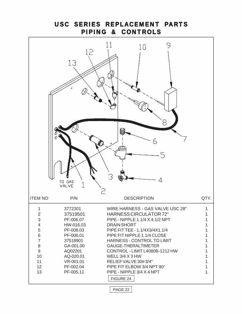
USC SERIES REPLAUSC SERIES REPLAUSC SERIES REPLAUSC SERIES REPLAUSC SERIES REPLACEMENT PCEMENT PCEMENT PCEMENT PCEMENT PARARARARARTSTSTSTSTSPIPING & CONTROLSPIPING & CONTROLSPIPING & CONTROLSPIPING & CONTROLSPIPING & CONTROLS
PAGE 22
FIGURE 24
ITEM NO P/N DESCRIPTION QTY.
1 3772301 WIRE HARNESS - GAS VALVE USC 28" 12 37519501 HARNESS CIRCULATOR 72" 13 PF-006.07 PIPE - NIPPLE 1.1/4 X 4.1/2 NPT 14 HW-016.03 DRAIN SHORT 15 PF-008.03 PIPE FIT TEE - 1.1/4X3/4X1.1/4 16 PF-006.01 PIPE FIT NIPPLE 1.1/4 CLOSE 17 37518901 HARNESS - CONTROL TO LIMIT 18 GA-001.00 GAUGE-THERALTIMETER 19 AQ02201 CONTROL - LIMIT L4080B-1212 HW 110 AQ-020.01 WELL 3/4 X 3 HW 111 VR-001.01 RELIEF VALVE 30# 3/4" 112 PF-002.04 PIPE FIT ELBOW 3/4 NPT 90° 113 PF-005.11 PIPE - NIPPLE 3/4 X 4 NPT 1

USC REPLAUSC REPLAUSC REPLAUSC REPLAUSC REPLACEMENT PCEMENT PCEMENT PCEMENT PCEMENT PARARARARARTS - ELECTRICALTS - ELECTRICALTS - ELECTRICALTS - ELECTRICALTS - ELECTRICAL
PAGE 23
FIGURE 25
ITEM NO P/N DESCRIPTION QTY.
1 SS00801 PRESSURE SWITCH (FS6205A) 12 3171101 TERMINAL STRIP COVER 13 EF03801 TRANSFORMERS - 40VA 24 RY-002.01 CONTROL R8222C-1008 15 HW09601 TUBING - SILICON - CLEAR 12"6 EF04001 9 TERM STRIP 17 HW09701 TUBING - SILICON - ORANGE 17"8 HW09001 SCREW 10-32X5/16 GREEN GROUND 19 3172701 PANEL CONTROL SUPPORT BRACKET 1
3772201 COMPLETE CONTROL BRACKET ASSEMBLY 1(THIS INCLUDES PART # 1,2,3,5,7,8, & ALL WIRING)

USC SERIES REPLAUSC SERIES REPLAUSC SERIES REPLAUSC SERIES REPLAUSC SERIES REPLACEMENT PCEMENT PCEMENT PCEMENT PCEMENT PARARARARARTSTSTSTSTSFLFLFLFLFLUE COLLECTUE COLLECTUE COLLECTUE COLLECTUE COLLECTOR & OR & OR & OR & OR & VENTER COMPONENTSVENTER COMPONENTSVENTER COMPONENTSVENTER COMPONENTSVENTER COMPONENTS
PAGE 24
FIGURE 26
ITEM # PART # DESCRIPTIONS QTY.
1 3472501 FLUE COLLECTOR ASSY USC3 13472502 FLUE COLLECTOR ASSY USC43472503 FLUE COLLECTOR ASSY USC5
2 345-2-7.01 VENT ADAPTER 13 HW-005.01 SCREW 1/4-20X1/2 SELF TAP 54 DC00402 VENTER USC - MAGNETEK 15 3571501 GASKET - VENTER USC 16 HW09501 BOLT 5/16"-18X1.1/2" TYPE F 2

USC SERIES REPLAUSC SERIES REPLAUSC SERIES REPLAUSC SERIES REPLAUSC SERIES REPLACEMENT PCEMENT PCEMENT PCEMENT PCEMENT PARARARARARTSTSTSTSTSTERMINTERMINTERMINTERMINTERMINAAAAATION KITTION KITTION KITTION KITTION KIT
ITEM # PART # DESCRIPTION QTY.
1 34721501 VENT TERMINATION THIMBLE PLATE ASSY 12 34721002 TERMINATION ASSEMBLY 13 34721401 VENT TERMINATION DEFLECTOR 14 HW-003.06 NUT #10-24 HEX 15 30A004312 SCREW #10-24 X 1.1/2" ROUND HEAD 16 3471701 DRAW COLLAR - USC 17 HW-009.01 SCR #8-18X1/2" SLT HX WASH 88 3471901 VENT TEMPLATE 1
5612601 TERMINATION KIT (INCLUDES ALL OF THE ABOVE)FIGURE 27
PAGE 25

FRO
NT
VIE
WR
IGH
T S
IDE
VIE
W
SE
ALE
D C
OM
BU
STI
ON
, DIR
EC
T V
EN
T S
ER
IES
BO
ILE
R
STA
ND
AR
D E
QU
IPM
EN
T B
oile
r Jac
ket,
Cas
t Iro
n B
oile
r Bat
tery
, Lim
it C
ontro
l, R
emov
able
Tra
nsfo
rmer
s, P
lug
in R
elay
, The
ralti
met
er G
auge
, Circ
ulat
or (f
ield
mou
nted
), M
ain
Gas
Bur
ners
, Hot
Sur
face
Pilo
t; A
.S.M
.E R
elie
f Val
ve, D
rain
Coc
k, In
duce
d D
raft
Fan,
Saf
ety
Pre
ssur
e S
witc
h, a
nd C
ombi
natio
n In
take
/Exh
aust
Ter
min
atio
n K
it.
All
boile
rs a
re d
esig
n ce
rtifie
d fo
r in
stal
latio
n on
non
-com
bust
ible
flo
ors.
For
inst
alla
tion
on c
ombu
stib
le f
loor
s, u
se c
ombu
stib
le f
loor
kit.
This
boi
ler
is a
Dire
ct V
ent D
esig
ned
Cer
tifie
d ap
plia
nce
whi
ch r
equi
res
asp
ecia
l hor
izon
tal t
hrou
gh t
he w
all v
entin
g sy
stem
. O
nly
HE
AT-
FAB
® S
AF-
T-VE
NT™
,FLE
X-L
® S
TAR
-34™
, P
roTe
ch™
Fas
NS
eal®
, an
d Z-
FLE
X®
Z-V
EN
T™ve
ntin
g m
ater
ial p
rodu
cts
shal
l be
used
.C
onsu
lt ven
ting
adde
ndum
for m
axim
um ve
nt le
ngth
s and
pro
per c
onfig
urat
ions
.E
lect
rical
ser
vice
to b
e 12
0 V
olts
, 15
Am
ps, 6
0 H
z.
Test
ed fo
r 100
lbs.
(689
.5 k
Pa)
AS
ME
Wor
king
Pre
ssur
e
3771201 REV: 6.3, September 2004
C. S
. A. C
ertif
ied
for
Nat
ural
gas
or P
ropa
ne
US
C S
ER
IES
Cas
t Ir
Cas
t Ir
Cas
t Ir
Cas
t Ir
Cas
t Ir
on,
on,
on,
on,
on,
Dir
Dir
Dir
Dir
Dir
ect
ect
ect
ect
ect
VVVV Ven
t S
eale
d C
omb
ent
Sea
led
Com
ben
t S
eale
d C
omb
ent
Sea
led
Com
ben
t S
eale
d C
omb u
stio
n,us
tion
,us
tion
,us
tion
,us
tion
, G
as-F
ir G
as-F
ir G
as-F
ir G
as-F
ir G
as-F
ired
,ed
,ed
,ed
,ed
, H
ot
Hot
H
ot
Hot
H
ot WWWW W
aaaa a ter
Boi
ler
ter
Boi
ler
ter
Boi
ler
ter
Boi
ler
ter
Boi
ler
RA
TIN
GS
AN
D D
IME
NS
ION
Boi
ler
A.G
.AH
eatin
gI=
B=R
Nat
ural
Dim
ensi
ons
Sup
ply
&N
o.W
ater
AFU
EIn
put
Cap
acity
Net
Out
put
Gas
Ret
urn
Of
No.
Btu
/Hr.
Btu
/Hr.
Btu
/Hr.
Inle
tA
BC
DTa
ppin
gsB
urne
rsC
onte
ntR
atin
gs
US
C3
50,0
0044
,000
38,0
001/
2"15
.1/8
"3.
1/2"
3.1/
2"5"
1.1/
4"2
4.0
gals
87%
(14.
7 K
W)
(12.
9 K
W)
(11.
1 K
W)
(1.2
7 cm
)(3
8 cm
)(9
cm
)(9
cm
)(1
2.7
cm)
(3.2
cm
)15
.14
liter
s
US
C4
100,
000
87,0
0076
,000
1/2"
19"
3.1/
2"3.
1/2"
6.1/
2"1.
1/4"
35.
6 ga
ls87
%(2
9.3
KW
)(2
5.5
KW)
(22.
3 KW
)(1
.27
cm)
(48
cm)
(9 c
m)
(9 c
m)
(16.
5 cm
)(3
.2 c
m)
21.2
0 lit
ers
US
C5
140,
000
122,
000
107,
000
1/2"
22.7
/8"
4.1/
4"4.
1/8"
8.3/
8"1.
1/4"
47.
2 ga
ls87
%(4
1.0
KW)
(35.
7 KW
)(3
1.3
KW)
(1.2
7 cm
)(5
8 cm
)(1
1 cm
)(1
1 cm
)(2
1.3
cm)
(3.2
cm
)27
.25
liter
sN
OTE
:Fo
r alti
tude
s ab
ove
2,00
0 ft.
ratin
gs s
houl
d be
redu
ced
at th
e ra
te o
f 4%
for e
ach
1,00
0 ft.
abo
ve s
ea le
vel.