3/8” frameless bypass sliding shower …€ frameless bypass sliding shower enclosure qci-5017...
TRANSCRIPT
3/8” FRAMELESS BYPASS SLIDINGSHOWER ENCLOSUREQCI-5017
INSTALLATIONINSTRUCTIONS
QCI5017 Rev. 2 Page 1 of 9 Certified 12/15/16
INSTALLATION NOTES: Unpack your unit carefully and inspect for freight damage. Lay out and identify all parts using the instruction sheet as a reference. Before discarding the carton, check to see that no small hardware parts have fallen to the bottom of the box. If any parts are damaged or missing, refer to the descriptions noted in the instructions when contacting your dealer for replacements.
Handle the glass panel(s) carefully and protect the edges.
Please wear safety glasses whenever drilling or cutting. When drilling holes in ceramic tile or marble, use a center punch and hammer to carefully break the surface glaze so the drill bit can start without skidding.
To install your New Shower Door you will need the following: tape measure, level(s), #2 Phillips screwdriver, drill, 1/8” & 3/16” High Speed Steel drill bits, hacksaw, pencil, sharp knife or razor blade and caulking (clear, mildew resistant silicone recommended). Optional tools include a miter box for cutting metal parts, file, center punch and masking tape. An additional 3/16” Masonry drill bit is recommended for tiled applications.
The doors are best installed with two people.
NOTE: Tempered glass cannot be cut.Although safety tempered glass is very resistant to breakage, the glass can still break if unequal pressure is placed on it during installation. Use caution! In addition, the sharp corners of the panel can damage tile and floor surfaces, so its best to handle the glass panels carefully and protect the edges.
MAINTENANCE: Two primary materials are used to manufacture your new Shower Enclosure: tempered glass and anodized aluminum. To assure a long lasting finish on the enclosure, wipe it down with a towel after each use. Never use a scouring pad/agent to clean the aluminum.
For occasional, more concentrated cleaning efforts, we recommend using LYSOL™ Non-Abrasive Bathroom Cleaner works extremely well. Be sure that any over spray falling on the aluminum frameis rinsed thoroughly and dried. Many over-the-counter cleaners, if applied to aluminum and left on, will harm the finish and cause permanent damage, even though their directions indicate safe use on shower doors.
For glass treated with AquaGlide™, read the following instructions:
After each use of your shower, use a small plastic bowl, pitcher or a hand held shower head to spray the shower doors with clean cold water. Pour or spray the cold water along the top edge of the glass. The majority of the shower’s soapy residual water will drain off. Use a small hand towel to pat dry the remaining droplets or use a squeegee to clear the droplets.
Once a month, use a nylon sponge to go over the wet glass, rubbing in a circular motion. You should feel “sticky” places going back to slick again. Then pour water along the top edge of the glass, as you do after each shower use.
QCI5017 Rev. 2 Page 2 of 9 Certified 12/15/16
QCI5017 Rev. 2 3 of 9
A
B
C
D
V
H
K
G F
E
W
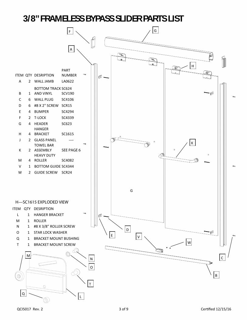
3/8” FRAMELESS BYPASS SLIDER PARTS LIST
ITEM QTY DESRIPTION PART NUMBER
A 2 WALL JAMB LA0622
B 1 BOTTOM TRACK AND VINYL
SC624 SCV190
C 6 WALL PLUG SC4106 D 6 #8 X 2" SCREW SCR15 E 4 BUMPER SC4294 F 2 T-LOCK SC4339 G 4 HEADER SC623
H 4 HANGER BRACKET SC1615
J 2 GLASS PANEL —-
K 2 TOWEL BAR ASSEMBLY SEE PAGE 6
M 4 HEAVY DUTY ROLLER SC4082
V 1 BOTTOM GUIDE SC4344 W 2 GUIDE SCREW SCR24
G
H—SC1615 EXPLODED VIEW
M
ITEM QTY DESRIPTION L 1 HANGER BRACKET M 1 ROLLER N 1 #8 X 3/8” ROLLER SCREW O 1 STAR LOCK WASHER Q 1 BRACKET MOUNT BUSHING T 1 BRACKET MOUNT SCREW
L
N
O
Q
T
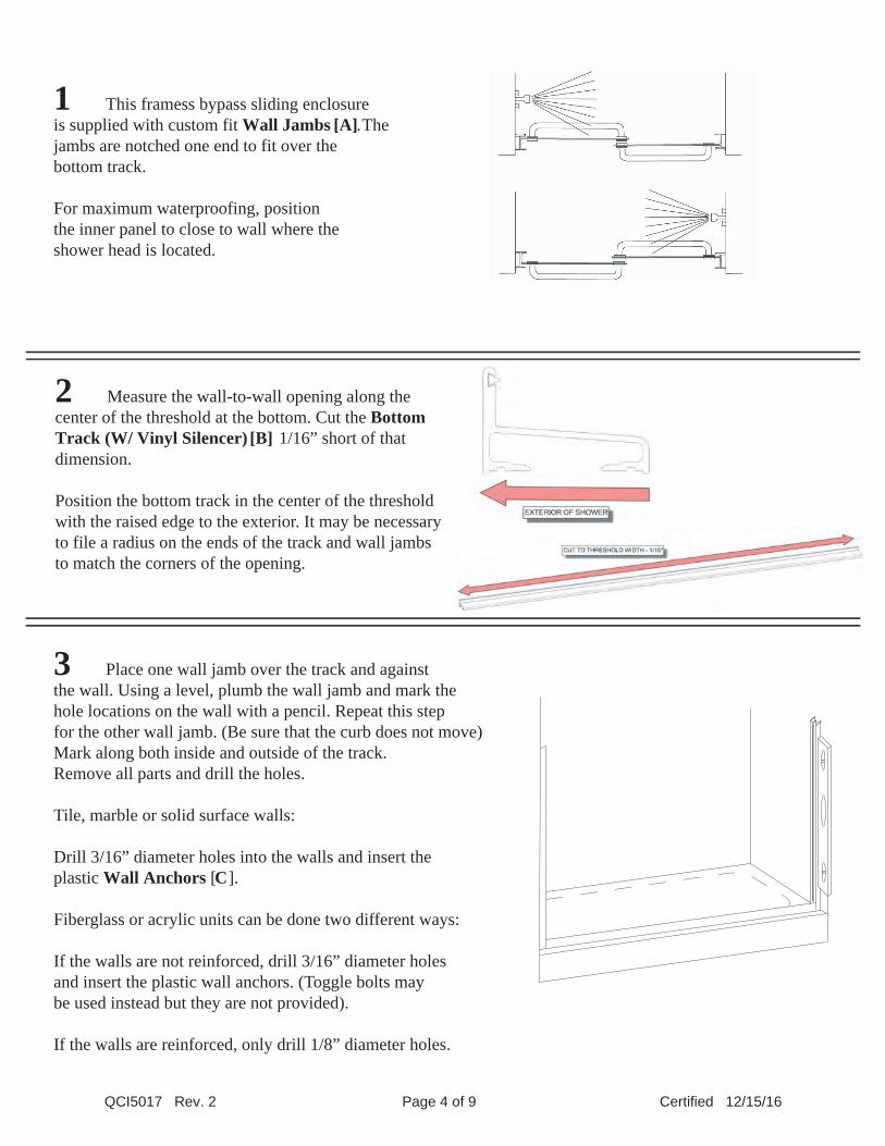
1 This framess bypass sliding enclosureis supplied with custom fit Wall Jambs [A] . The jambs are notched one end to fit over the bottom track.
For maximum waterproofing, position the inner panel to close to wall where the shower head is located.
2 Measure the wall-to-wall opening along thecenter of the threshold at the bottom. Cut the BottomTrack (W/ Vinyl Silencer) [B] 1/16” short of thatdimension.
Position the bottom track in the center of the thresholdwith the raised edge to the exterior. It may be necessaryto file a radius on the ends of the track and wall jambsto match the corners of the opening.
3 Place one wall jamb over the track and against the wall. Using a level, plumb the wall jamb and mark the hole locations on the wall with a pencil. Repeat this step for the other wall jamb. (Be sure that the curb does not move)Mark along both inside and outside of the track. Remove all parts and drill the holes.
Tile, marble or solid surface walls:
Drill 3/16” diameter holes into the walls and insert the plastic Wall Anchors [C].
Fiberglass or acrylic units can be done two different ways:
If the walls are not reinforced, drill 3/16” diameter holes and insert the plastic wall anchors. (Toggle bolts may be used instead but they are not provided).
If the walls are reinforced, only drill 1/8” diameter holes.
QCI5017 Rev. 2 Page 4 of 9 Certified 12/15/16
SILICONE
QCI5017 Rev. 2 Page 5 of 9 Certified 12/15/16
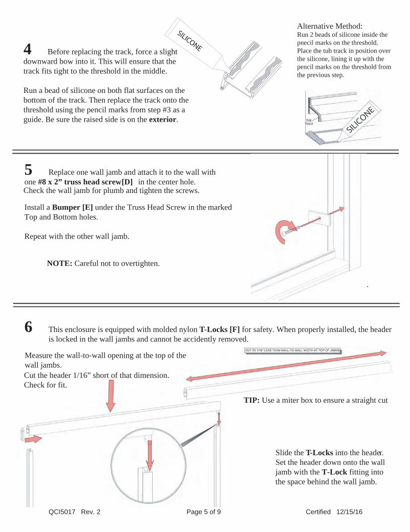
4 Before replacing the track, force a slight downward bow into it. This will ensure that thetrack fits tight to the threshold in the middle.
Run a bead of silicone on both flat surfaces on thebottom of the track. Then replace the track onto thethreshold using the pencil marks from step #3 as a guide. Be sure the raised side is on the exterior.
5 Replace one wall jamb and attach it to the wall withone #8 x 2” truss head screw [D] in the center hole. Check the wall jamb for plumb and tighten the screws.
Repeat for the other wall jamb.
NOTE: Careful not to overtighten.
Install a Bumper [E] under the Truss Head Screw in the markedTop and Bottom holes.
Repeat with the other wall jamb.
6 This enclosure is equipped with molded nylon T-Locks [F] for safety. When properly installed, the headeris locked in the wall jambs and cannot be accidently removed.
Slide the T-Locks into the header.Set the header down onto the walljamb with the T-Lock fitting into the space behind the wall jamb.
Measure the wall-to-wall opening at the top of the wall jambs.Cut the header 1/16” short of that dimension. Check for fit.
TIP: Use a miter box to ensure a straight cut
Alternative Method:Run 2 beads of silicone inside the pnecil marks on the threshold.Place the tub track in position over the silicone, lining it up with the pencil marks on the threshold from the previous step.
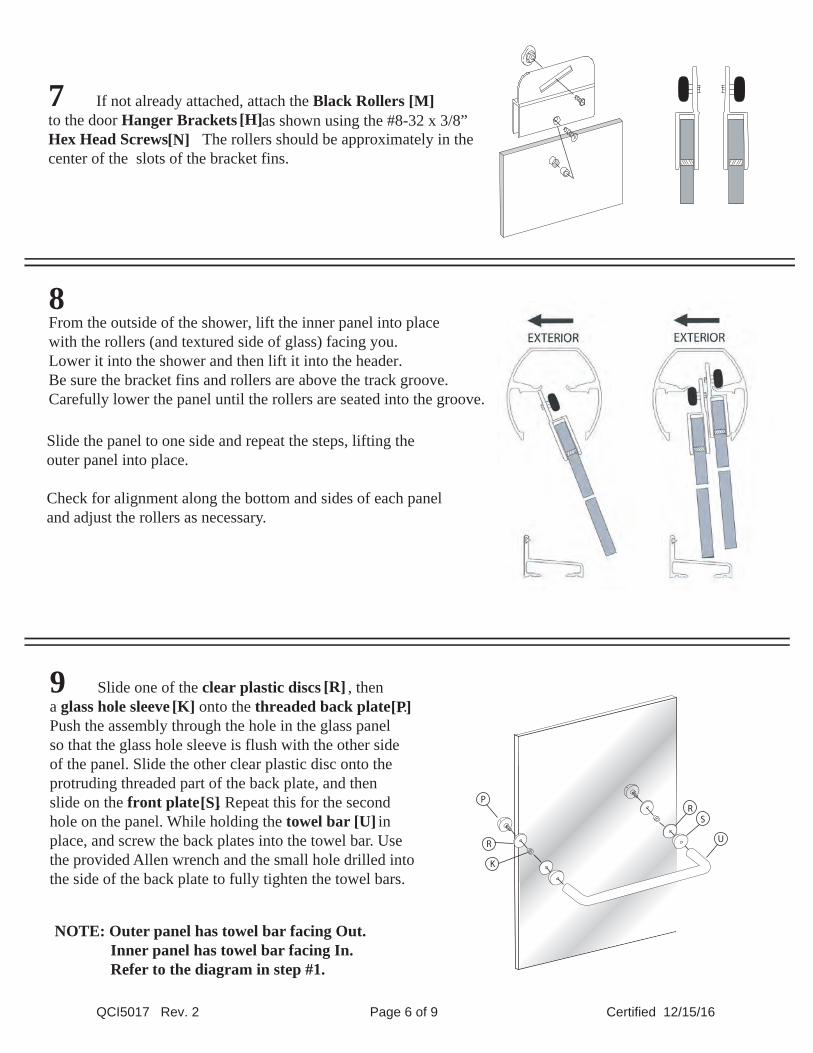
7 If not already attached, attach the Black Rollers [M] to the door Hanger Brackets [H] as shown using the #8-32 x 3/8”Hex Head Screws [N]. The rollers should be approximately in thecenter of the slots of the bracket fins.
8 From the outside of the shower, lift the inner panel into place with the rollers (and textured side of glass) facing you. Lower it into the shower and then lift it into the header.Be sure the bracket fins and rollers are above the track groove. Carefully lower the panel until the rollers are seated into the groove.
Slide the panel to one side and repeat the steps, lifting theouter panel into place.
Check for alignment along the bottom and sides of each paneland adjust the rollers as necessary.
9 Slide one of the clear plastic discs [R] , then a glass hole sleeve [K] onto the threaded back plate [P]. Push the assembly through the hole in the glass panel so that the glass hole sleeve is flush with the other side of the panel. Slide the other clear plastic disc onto the protruding threaded part of the back plate, and thenslide on the front plate [S]. Repeat this for the secondhole on the panel. While holding the towel bar [U] in place, and screw the back plates into the towel bar. Usethe provided Allen wrench and the small hole drilled into the side of the back plate to fully tighten the towel bars.
NOTE: Outer panel has towel bar facing Out. Inner panel has towel bar facing In. Refer to the diagram in step #1.
U
SR
P
R
K
QCI5017 Rev. 2 Page 6 of 9 Certified 12/15/16
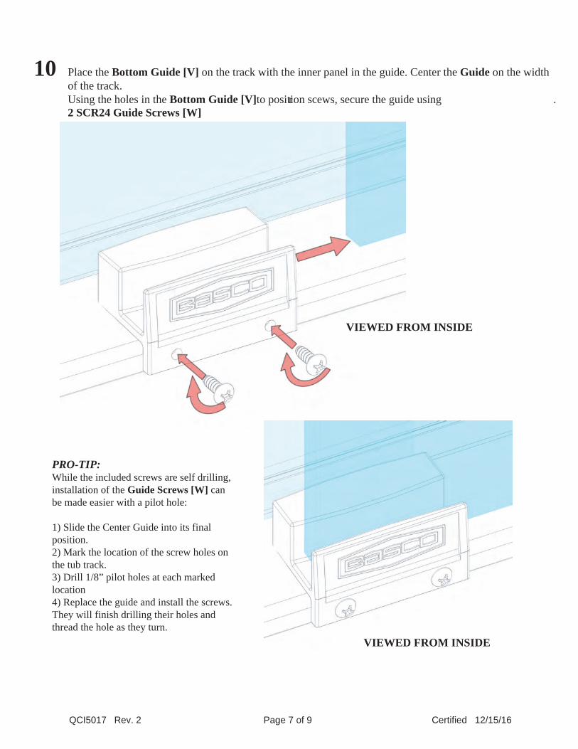
10 Place the Bottom Guide [V] on the track with the inner panel in the guide. Center the Guide on the widthof the track.Using the holes in the Bottom Guide [V]to position scr ews, secure the guide using 2 SCR24 Guide Screws [W]
.
QCI5017 Rev. 2 Page 7 of 9 Certified 12/15/16
VIEWED FROM INSIDE
VIEWED FROM INSIDE
PRO-TIP:While the included screws are self drilling, installation of the Guide Screws [W] can be made easier with a pilot hole:
1) Slide the Center Guide into its final position. 2) Mark the location of the screw holes on the tub track. 3) Drill 1/8” pilot holes at each marked location4) Replace the guide and install the screws. They will finish drilling their holes and thread the hole as they turn.
QCI5017 Rev. 2 Page 8 of 9 Certified 12/15/16
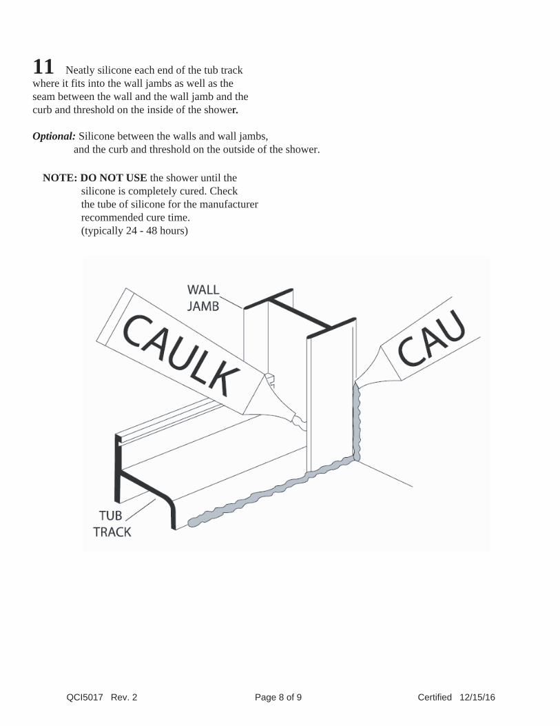
11 Neatly silicone each end of the tub track where it fits into the wall jambs as well as the seam between the wall and the wall jamb and the curb and threshold on the inside of the shower.
Optional: Silicone between the walls and wall jambs, and the curb and threshold on the outside of the shower.
r.
NOTE: DO NOT USE the shower until the silicone is completely cured. Check the tube of silicone for the manufacturer recommended cure time. (typically 24 - 48 hours)
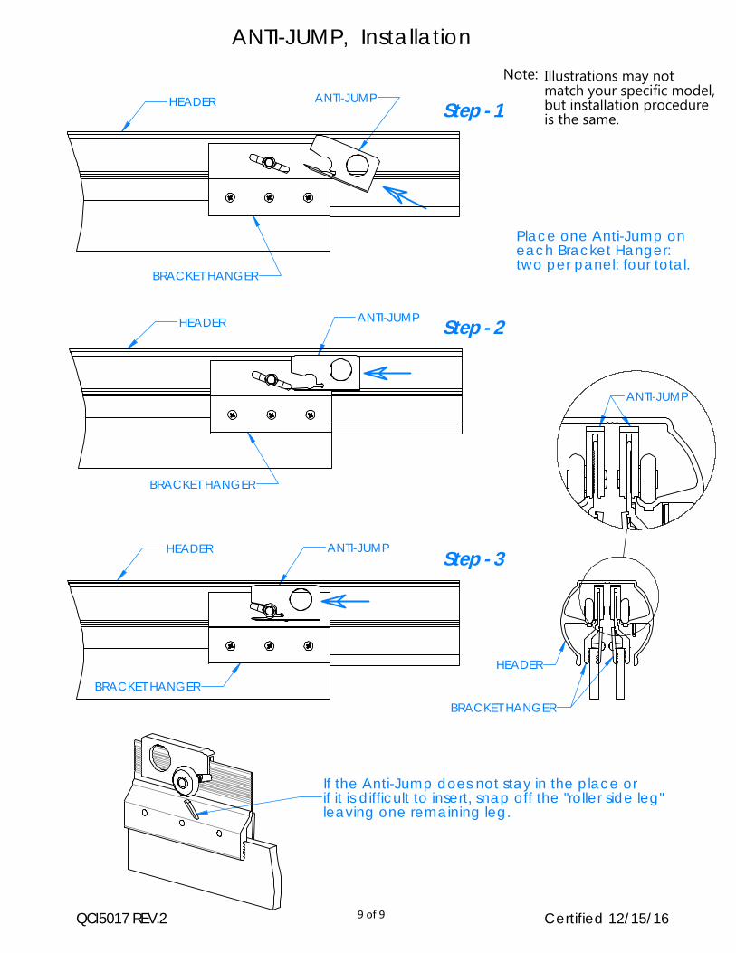
ANTI-JUMPHEADER
BRACKET HANGER
Place one Anti-Jump on each Bracket Hanger: two per panel: four total.
QCI5017 REV.2
Note:
Certified 12/15/16
HEADER
BRACKET HANGER
ANTI-JUMP
BRACKET HANGER
HEADER ANTI-JUMP
HEADER
BRACKET HANGER
ANTI-JUMP
If the Anti-Jump does not stay in the place or if it is difficult to insert, snap off the "roller side leg"leaving one remaining leg.
ANTI-JUMP, Installation
Step - 1
Step - 2
Step - 3
Illustrations may notmatch your specific model,but installation procedureis the same.
9 of 9