389 04 00 00 hand - delta light€¦ · 2x 1x din 911/2 1x din 911/1,5 1x 2x 1x din911 1x /2 ......
TRANSCRIPT

Installation Instruction
1Ref: 389 04 00 00
STREAMLINER
TRIMLESS PROFILEA
A
B
B
A+
SRL TR - PROFILE
SRL TR - PROFILE
389 04 00 00
96
70
85
Cutout type Square
Cutout size 90 x (L+5)mm
Recessed depth 125mm
Min. Thickness ceiling Min. 6mm
Max. Thickness ceiling Max. 25mm
Max lenght pro!le 6m
Max power per feed at 120V 400W
Max power per feed at 240V 800W
Last Update ALLU 17/02/2017
90 x ( L + 5 ) x 125 mm
90
1
2
3
L + 5
100
100
600
600
600
X
X > 700 ==> + 1
18,590
18,5
4
1X1X
SRL TR - CLIP
SRL TR - CLIP
389 04 14 01
FIXATION
90 x ( L + 5 ) x 125 mm
ACCESSORY SET
POSITION FOR INSTALLATION
X > 700 ==> + 1
3 3
2Ref: 389 04 00 00
Installation Instruction
5
6
7
8
5b
plaster plaster
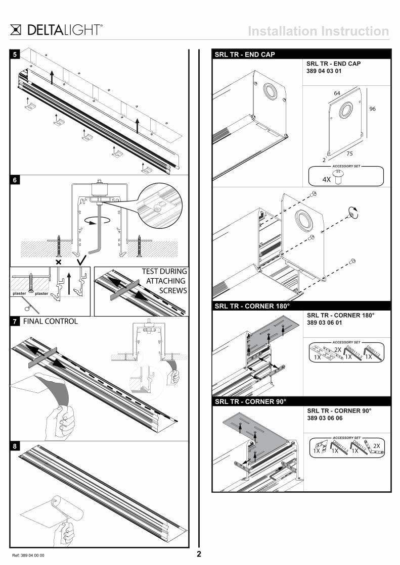
SRL TR - END CAP
SRL TR - CORNER 180°
SRL TR - END CAP
389 04 03 01
ACCESSORY SET
ACCESSORY SET
4X
64
752
96
SRL TR - CORNER 180°
389 03 06 01
SRL TR - CORNER 90°
ACCESSORY SET
SRL TR - CORNER 90°
389 03 06 06
1X2X
1X
DIN911/21X
DIN911/1,5
1X2X
1X
DIN911/21X
DIN911/1,5
TEST DURING
ATTACHING
SCREWS
FINAL CONTROL
3Ref: 389 03 00 00
Installation Instruction
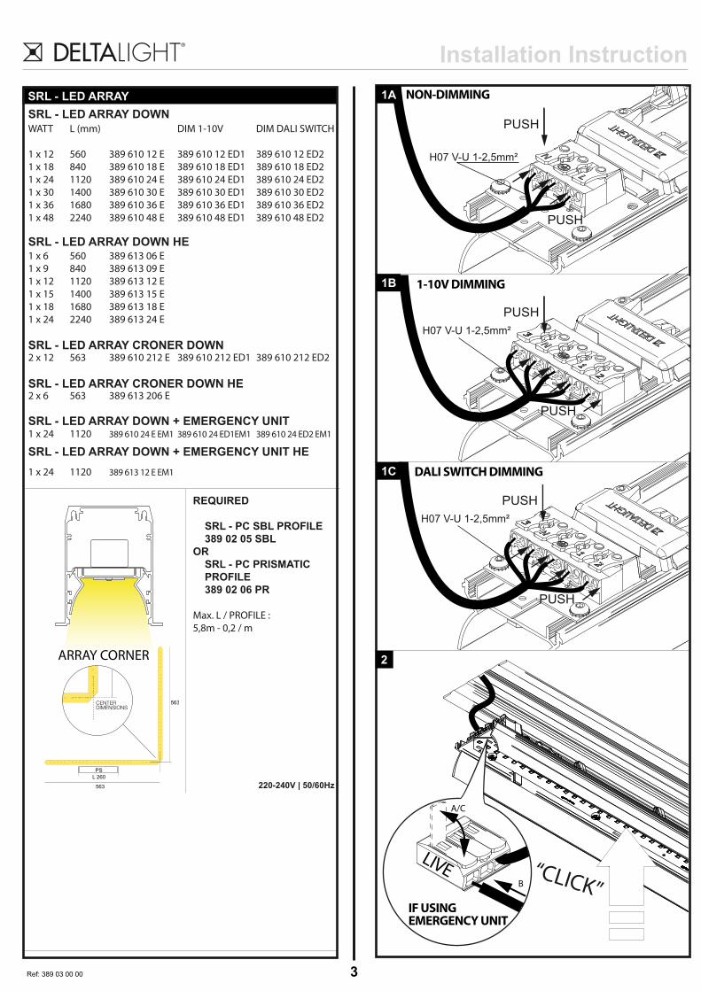
SRL - LED ARRAY
WATT
1 x 12
1 x 18
1 x 24
1 x 30
1 x 36
1 x 48
1 x 6
1 x 9
1 x 12
1 x 15
1 x 18
1 x 24
2 x 12
2 x 6
1 x 24
1 x 24
L (mm)
560
840
1120
1400
1680
2240
560
840
1120
1400
1680
2240
563
563
1120
1120
389 610 12 E
389 610 18 E
389 610 24 E
389 610 30 E
389 610 36 E
389 610 48 E
389 613 06 E
389 613 09 E
389 613 12 E
389 613 15 E
389 613 18 E
389 613 24 E
389 610 212 E
389 613 206 E
389 610 24 E EM1
389 613 12 E EM1
DIM 1-10V
389 610 12 ED1
389 610 18 ED1
389 610 24 ED1
389 610 30 ED1
389 610 36 ED1
389 610 48 ED1
389 610 212 ED1
389 610 24 ED1EM1
DIM DALI SWITCH
389 610 12 ED2
389 610 18 ED2
389 610 24 ED2
389 610 30 ED2
389 610 36 ED2
389 610 48 ED2
389 610 212 ED2
389 610 24 ED2 EM1
220-240V | 50/60Hz
2
PUSH
PUSH
10
10
10
REQUIRED
SRL - PC SBL PROFILE
389 02 05 SBL
OR
SRL - PC PRISMATIC
PROFILE
389 02 06 PR
Max. L / PROFILE :
5,8m - 0,2 / m
H07 V-U 1-2,5mm²
1A
PUSH
H07 V-U 1-2,5mm²
1B
L 260
563
563
PS
CENTERDIMENSIONS
SRL - LED ARRAY DOWN
SRL - LED ARRAY DOWN + EMERGENCY UNIT
SRL - LED ARRAY DOWN + EMERGENCY UNIT HE
SRL - LED ARRAY CRONER DOWN
SRL - LED ARRAY CRONER DOWN HE
SRL - LED ARRAY DOWN HE
ARRAY CORNER
NON-DIMMING
1-10V DIMMING
1C DALI SWITCH DIMMING
“CLICK”
A/C
B
IF USING EMERGENCY UNIT
LIVE
PUSH
10
10
10
10
10
PUSH
H07 V-U 1-2,5mm²
PUSH
10
10
10
10
10

Installation Instruction
4Ref: 389 03 00 00
Installation Instruction
REMOVAL OF A SRL - LED ARRAY
REMOVAL OF A SRL - LED ARRAY
BPULL
APUSH
2X / Module
MIDISPY M10
ACCESSORY SET
MIDISPY M10
M10 241 933
M10 241 923
Beschermd tegen vaste voorwerpen die groter zijn dan 12 mm
Protégé contre les objets solides de plus de 12 mm
Geschützt gegen Festkörper größer als 12 mm
Protected against solid objects greater than 12 mm
Protegido contra objetos sólidos superiores a 12 mm
Protetto contro oggetti solidi più grandi di 12 mm
Enkel geschikt voor toestellen op zeer lage spanning (minder dan 50 V-AC / 120 V-DC)
Convient uniquement pour les produits à très basse tension (moins de 50 V-AC / 120 V-DC)
Geeignet für Güter mit sehr niedriger Spannung (unter 50 V-AC / 120 V-DC)
Only suited for goods at very low voltage (below 50 V-AC / 120 V-DC)
Se recomieda únicamente para aquellos productos de tensión muy baja (menos de 50 V-AC / 120 V-DC)
Vale unicamente per i prodotti a tensione molto bassa (inferiore a 50 V-AC / 120 V-DC)
x1x1
DIN911/1,5
REQUIRED
MIDISPY TUBE
414 03 00
74 ø45
90°
355°
1
CLICK!
REQUIREMENTS
MIDISPY TUBE
414 03 00
3
2
2X / Module
REQUIRED / EXAMPLESRL - M10 MIDISPY / SPY1
389 90 01
Start position
demounting
Installation Instruction
5Ref: 389 03 00 00
Installation Instruction
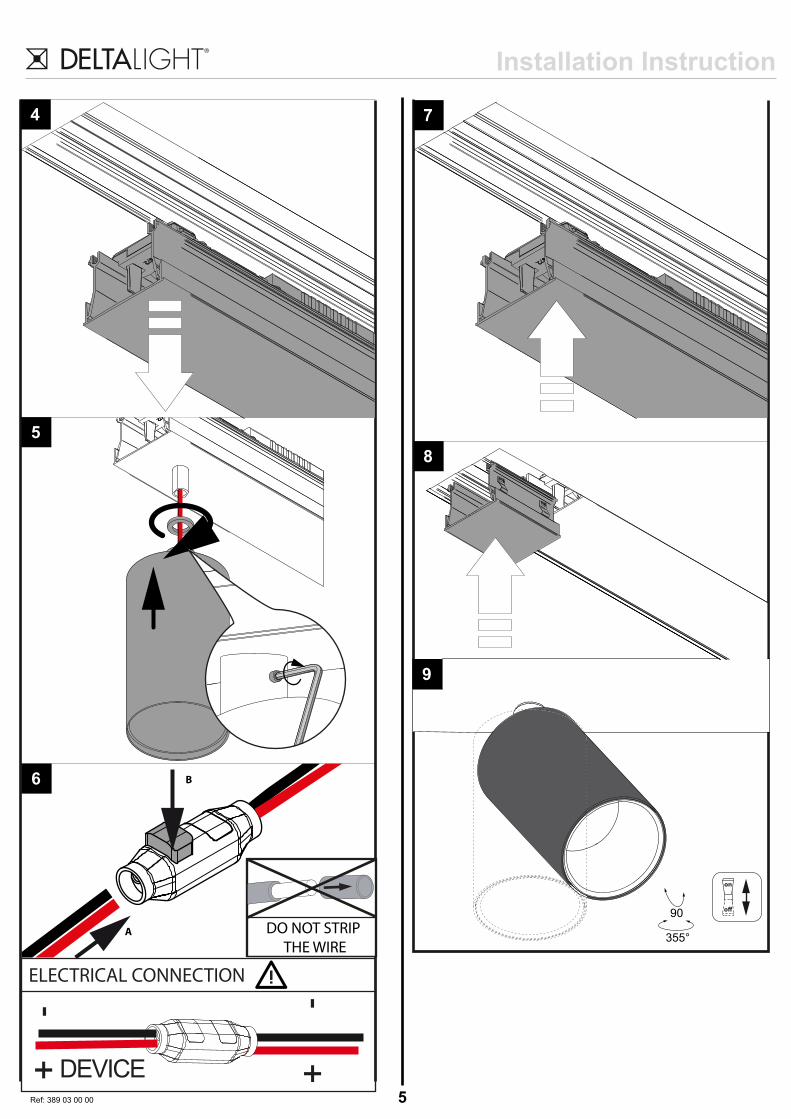
4
5
6
DEVICE
ELECTRICAL CONNECTION
-+
-+
B
A DO NOT STRIP
THE WIRE
9
on
o
355°
90
7
8

Installation Instruction
6Ref: 389 03 00 00
Installation Instruction
SPY M10
ACCESSORY SET
SPY M10
M10 341 81931
M10 341 81932
M10 341 81921
M10 341 81922
Beschermd tegen vaste voorwerpen die groter zijn dan 12 mm
Protégé contre les objets solides de plus de 12 mm
Geschützt gegen Festkörper größer als 12 mm
Protected against solid objects greater than 12 mm
Protegido contra objetos sólidos superiores a 12 mm
Protetto contro oggetti solidi più grandi di 12 mm
Enkel geschikt voor toestellen op zeer lage spanning (minder dan 50 V-AC / 120 V-DC)
Convient uniquement pour les produits à très basse tension (moins de 50 V-AC / 120 V-DC)
Geeignet für Güter mit sehr niedriger Spannung (unter 50 V-AC / 120 V-DC)
Only suited for goods at very low voltage (below 50 V-AC / 120 V-DC)
Se recomieda únicamente para aquellos productos de tensión muy baja (menos de 50 V-AC / 120 V-DC)
Vale unicamente per i prodotti a tensione molto bassa (inferiore a 50 V-AC / 120 V-DC)
x1x1
DIN911/1,5
111 ø62
90°
355°
REQUIRED
SPY TUBE 414 01 00
ACCESSORIES
HONEYCOMB 50 413 03 01
LINEAR SPREAD
LENS 50 413 03 02
SPREAD LENS 50 413 03 03
SOFTENING LENS 50 413 03 04
GLASS SBL 50 413 03 05
SPY TUBE
414 01 00
Click!!
1
2
3
4
5
2X / Module
REQUIRED / EXAMPLESRL - M10 MIDISPY / SPY1
389 90 01
6
Start position
demounting

Installation Instruction
7Ref: 389 03 00 00
Installation Instruction
8
DEVICE
ELECTRICAL CONNECTION
-+
-+
B
A DO NOT STRIP
THE WIRE
7
11
on
o
355°
90
9
10

8Ref: 389 03 00 00
Installation InstructionACCESSORIES
2
3
Used as replacement
lens1
HONEYCOMB 50
413 03 01
LINEAR SPREAD LENS 50
413 03 02
SPREAD LENS 50
413 03 03
SOFTENING LENS 50
413 03 04
GLASS SBL 50
413 03 05
Click!!
ROUGH SIDEFLAT SIDE
ROUGH SIDE
SPY TUBE
414 01 00
SPY HP M10
ACCESSORY SET
SPY HP M10
M10 341 21 931
M10 341 21 921
Beschermd tegen vaste voorwerpen die groter zijn dan 12 mm
Protégé contre les objets solides de plus de 12 mm
Geschützt gegen Festkörper größer als 12 mm
Protected against solid objects greater than 12 mm
Protegido contra objetos sólidos superiores a 12 mm
Protetto contro oggetti solidi più grandi di 12 mm
Enkel geschikt voor toestellen op zeer lage spanning (minder dan 50 V-AC / 120 V-DC)
Convient uniquement pour les produits à très basse tension (moins de 50 V-AC / 120 V-DC)
Geeignet für Güter mit sehr niedriger Spannung (unter 50 V-AC / 120 V-DC)
Only suited for goods at very low voltage (below 50 V-AC / 120 V-DC)
Se recomieda únicamente para aquellos productos de tensión muy baja (menos de 50 V-AC / 120 V-DC)
Vale unicamente per i prodotti a tensione molto bassa (inferiore a 50 V-AC / 120 V-DC)
x1x1
DIN911/1,5
111 ø62
90°
355°
REQUIRED SPY TUBE 414 01 00
ACCESSORIES HONEYCOMB 50 413 03 01
LINEAR SPREAD
LENS 50 413 03 02
SPREAD LENS 50 413 03 03
SOFTENING LENS 50 413 03 04
GLASS SBL 50 413 03 05
SPY TUBE
414 01 00
Click!!
1
2
3
REQUIRED / EXAMPLESRL - M10 SPY HP 1
389 91 01
4
5
2X / Module
Start position
demounting

9Ref: 389 03 00 00
Installation InstructionInstallation Instruction
7
6
1
8
DEVICE
ELECTRICAL CONNECTION
-+
-+
B
A DO NOT STRIP
THE WIRE
9
10

10Ref: 389 03 00 00
Installation Instruction
1ACCESSORIES
2
3
Used as replacement
lens
1
HONEYCOMB 50
413 03 01
LINEAR SPREAD LENS 50
413 03 02
SPREAD LENS 50
413 03 03
SOFTENING LENS 50
413 03 04
GLASS SBL 50
413 03 05
Click!!
ROUGH SIDEFLAT SIDE
ROUGH SIDE
SPY TUBE
414 01 00
SRL 1 LED
SRL 1 LED
389 611 933
389 611 923
Beschermd tegen vaste voorwerpen die groter zijn dan 12 mm
Protégé contre les objets solides de plus de 12 mm
Geschützt gegen Festkörper größer als 12 mm
Protected against solid objects greater than 12 mm
Protegido contra objetos sólidos superiores a 12 mm
Protetto contro oggetti solidi più grandi di 12 mm
Voorzien van aardingsaansluiting
Avec mise à la terre
Ausgerüs tet mit Erdungsanschluss
Provided with grounding
Con la toma de tierra
Con presa a terra
H07-VU1-2,5mm²10
PUSH
B
PU
SH
A
2
“CLICK”
on
o#
355°
90
11
Minimum length: 250mm
Maximum length : 6m
Di!erent modules can be combined.
Opgepast warm oppervlak - niet aanraken - buiten bereik installeren
Attention surface de contact chaude - ne pas toucher - installer hors d'atteinte
Achtung heisse Oberfläche - Nicht Berühren - Nur unerreichbar installeren
Caution hot surface - do not touch - install out of reach
Precaucion alta temperatura de la superficie - no tocar - instalar fuera de alcance
Attenzione superficie calda - non toccare - installare in luogo non accessibile

11Ref: 389 03 00 00
Installation Instruction
SRL 2 LED
SRL 2 LED
389 612 933
389 612 923
Beschermd tegen vaste voorwerpen die groter zijn dan 12 mm
Protégé contre les objets solides de plus de 12 mm
Geschützt gegen Festkörper größer als 12 mm
Protected against solid objects greater than 12 mm
Protegido contra objetos sólidos superiores a 12 mm
Protetto contro oggetti solidi più grandi di 12 mm
Voorzien van aardingsaansluiting
Avec mise à la terre
Ausgerüs tet mit Erdungsanschluss
Provided with grounding
Con la toma de tierra
Con presa a terra
1
2
“CLICK”
H07-VU1-2,5mm²10
PUSH
B
PUSH
A
REMOVAL OF A SRL MODULE.
1
2
2X / Module
REQUIRED / EXAMPLESRL - M10 MIDISPY / SPY1
389 90 01
3
Start position
demounting
Minimum length: 450mm
Maximum length : 6m
Di!erent modules can be combined.
Installation Instruction
Ref: ceiling finishing
Ceiling finishing for trimless kits and trimless ProfilesA good result after installing a trimless Kit/ trimless profile is achieved by finishing the gap between the Kit/ Profile and ceiling with a
two-component filler. A normal filler hardens because the water or turpentine evaporates out of it. The result is a final layer which is
flatter than the layer that was put originally. A two-component filler hardens by a chemical reaction between 2 different components and
remains at the same level as applied. A two-component filler is composed of an asbestos free polyester resin, that, when mixed with a
hardener, turns into a filler which then sets and hardens. They typically remain elastic, are easy to sand and they have a high filling
capacity. This is the type of filler we recommend when installing our mounting/trimless Kits and the profiles Splitline, Borderline, Endless
Trimless, Uniline TR and Uniline TRT. Corresponding sequence :
1) Install the kit or profile – see corresponding manual
2) Apply the 2 component filler
3) Sand if necessary to the proper shape
4) Prime and paint like the ceiling or wall
5) Install the luminary in the Kit – see corresponding manual
Remark on trimless profiles : For a perfect finish between endcap and ceiling : leave a gap of 3mm between endcap and ceiling and fill
this gap with a elastic filler such as silicone which can be painted over.
Plafondafwerking bij toepassing van Trimless kits en trimless profielenOm een goed resultaat te bekomen na installatie van een trimless kit of trimless profiel dient de opening tussen kit/profiel en plafond
afgewerkt te worden met een 2-componenten vulpasta. Een gewone vulpasta hardt uit doordat het water of de terpentijn eruit verdampt.
Het resultaat is een finale laag die dunner is dan de oorspronkelijk aangebrachte laag. Een 2-componenten vulpasta hardt uit door een
chemische reactie tussen twee verschillende componenten en blijft z’n dikte behouden zoals aangebrach Et.en 2-componenten vulpasta
bestaat uit een asbest vrije polyester die, na menging met een verharder, een pasta vormt die dan uithard.
De typische kenmerken zijn : behouden van een zekere elasticiteit, gemakkelijk te wrijven en een hoog vullendvermogen. Dit is het type
van vulpasta die wij aanbevelen voor het afwerken van onze mounting/trimless kits en de profielen: Splitline, Borderline, Endless
Trimless, Uniline TR en Uniline TRT. Te volgen stappen :
1) Installeer de kit of profiel – Zie corresponderende handleiding
2) Pas de 2-componenten vulpasta toe
3) Zo nodig bijwerken met glaspapier
4) Aanbrengen van de grondlaag en afwerkingslaag
5) Installeer het toestel in de Kit – Zie corresponderende handleiding
Opmerking bij trimless profielen : Om een perfecte afwerking te bekomen tussen eindplaat en plafond: voorzie een speling van 3mm
tussen eindplaat en plafond en vul die met een elastische kit zoals een overschilderbare silicone.
Finition plafond pour les kits trimless ou profilés trimless (sans rebord)Afin d’avoir un résultat impeccable en installant un kit trimless ou profilé trimless est d’utiliser un joint 2 composants pour remplir le
trou. Un joint normal devient dur puisque l’eau ou thérébenthine s’évapore trop vite et donne ainsi une fine couche de finition plutôt
qu’un joint bien rempli. Un joint de 2 composants se durcit plus vite car c’est une réaction chimique de 2 composants différents mais
qui se maintient dès l’application. Le joint des 2 composants est scindé par de la résine en polyester libre d’amiante que lorsqu’il est
mélangé avec un durcisseur, celui-ci se définit et se durcit. Il reste élastique, facile à polir et a une capacité de remplissage élevé.
C’est pourquoi on conseille d’utiliser ce mélange pour l’installation des kits ou profilés trimless comme notre Splitline, Borderline,
Endless trimless, Uniline TR ou Uniline TRT. A utiliser comme les étapes suivantes :
1) installer le kit ou profilé : voir le manuel correspondant
2) appliquer le joint 2 composants
3) si nécessaire utiliser du papier de verre
4) mettez une couche primer puis mettez en peinture
5) installez le luminaire dans le kit – voir manuel correspondant
Remarque pour le montage d’un profilé trimless : pour obtenir une finition impeccable entre les embouts et le plafond, laisser une
distance de 3 mm et recouvrir le trou par un mastique élastique ou silicone qui peut être mis en peinture.
Decken Fertigstellung für Trimless (randlose) Kits und Trimless ProfileEin gutes Ergebnis nach der Installation eines Trimless Kits / Trimless Profils wird erreicht, wenn die Lücke zwischen dem Kit / Profil
und der Decke mit einem Zweikomponenten-Füller verschlossen wird. Ein normaler Füller härtet, weil das Wasser oder Terpentin aus
ihm heraus verdunstet. Das Ergebnis ist eine Füllschicht, die flacher ist als die ursprüngliche aufgetragene Schicht.
Ein Zweikomponenten-Füller härtet mittels einer chemischen Reaktion von 2 verschiedenen Komponenten aus und bleibt auf der
gleichen Ebene wie aufgebracht. Ein Zweikomponenten-Füller ist aus einem asbestfreien Polyesterharz zusammengesetzt, das beim
Vermischen mit einem Härter zu einem Füllstoff wird der sich setzt und aushärtet. Er bleibt in der Regel elastisch, ist leicht zu
verarbeiten/streichen und hat eine hohe Füllkraft. Das ist der Typ von Füllstoff den wir zur Installation unsere Montage/Randlos Kits und
den Profilen Splitline, Borderline, Endless Trimless, Uniline TR und Uniline TRT empfehlen. Entsprechende Reihenfolge:
1) Installation des Kits oder Profiles – siehe entsprechende Anleitung
2) Anwenden des Zweikomponenten-Füllers
3) Wenn nötig in die richtige Form bringen, z.B. durch Schleifen
4) In der Farbe der Decke oder Wand streichen
5) Installieren Sie die Leuchte in das Kit – siehe entsprechende Anleitung
Bemerkung zu trimless Profilen : Für eine perfekte Verarbeitung zwischen Endkappe und Decke : lassen Sie einen Abstand von 3 mm
zwischen Endkappe und Decke und füllen Sie diesen Spalt mit einem elastischen Füllstoff wie z.B. Silikon aus, den Sie noch mit Farbe
streichen können