39 implementing an application specific instruction-set ... · 39 implementing an application...
TRANSCRIPT

39
Implementing an Application Specific Instruction-set Processor forSystem Level Dynamic Program Analysis Engines
Ingoo Heo, Seoul National UniversityMinsu Kim, Korea Advanced Institute of Science and TechnologyYongje Lee, Samsung Electronics Co., Ltd and Seoul National UniversityChangho Choi, Korea Advanced Institute of Science and TechnologyJinyong Lee, Seoul National UniversityBrent Byunghoon Kang, Korea Advanced Institute of Science and TechnologyYunheung Paek, Seoul National University
In recent years, dynamic program analysis (DPA) has been widely used in various fields such as profil-ing, finding bugs and security. However, existing solutions have their own weaknesses. Software solutionsprovide flexibility in DPA but they suffer from tremendous performance overhead. In contrast, core-levelhardware engines rely on specialized integrated logics and attain extremely fast computation, but they havea limited functional extensibility because the logics are tightly coupled with the host processor. To mendthis, a prior system level approach utilizes an existing channel to integrate their hardware without necessi-tating the host architecture modification and introduced great potential in performance. Nevertheless, theprior work did not address the detailed design and implementation of the engine, which is quite essentialto leverage the deployment on real systems. To address this, in this paper, we propose an implementationof programmable DPA hardware engine, called program analysis unit (PAU). PAU is an application specificinstruction-set processor (ASIP) whose instruction-set is customized to reflect common features of variousDPA methods. With the specialized architecture and programmability of software, our PAU aims at fastcomputation and sufficient flexibility. In our case studies on several DPA techniques, we show that our ASIPapproach can be successfully applicable to complex DPA schemes while providing hardware-backed powerin performance and software-based flexibility in analysis. Recent experiments on our FPGA prototype re-vealed that the performance of PAU is 4.7-13.6 times faster than pure software DPA, and the power/areaconsumption is also acceptably small compared to today’s mobile processors.
Categories and Subject Descriptors: C.3 [Computer Systems Organiztion]: Special-Purpose andApplication-Based Systems
General Terms: Design, Performance, Algorithm
This work was partly supported by the IT R&D program of MSIP/KEIT [K10047212, Development of ho-momorphic encryption supporting arithmetics on ciphertexts of size less than 1kB and its applications], theBrain Korea 21 Plus Project in 2015, IDEC and the National Research Foun- dation of Korea(NRF) grantfunded by the Korea government(MSIP) (No. 2014R1A2A1A10051792). Also, this research was supportedby the MSIP(Ministry of Science, ICT & Future Planning), Korea, under the BrainScoutingProgram(H7106-14-1011) supervised by the IITP(Institute for Information & Communication Promotion), and Agency forDefense Development (ADD) under Grant No. UD140002ED.Author’s addresses : I.Heo, Y.Lee, J.Lee and Y.Paek, Department of Electrical and Computer En-gineering and Inter-University Semiconductor Research Center (ISRC), Seoul National University, 1Gwanak-ro, Gwanak-gu, Seoul, 151-742, South Korea; email:[email protected], [email protected],[email protected],[email protected]; M.Kim(co-primary author), C.Choi and B.B.Kang, Graduate School ofInformation Security, Korea Advanced Institute of Science and Technology, 291 Daehak-ro, Yuseong-gu,Daejeon, 305-701, South Korea; email:[email protected], [email protected], [email protected] authors : Y.Paek and B.B.KangPermission to make digital or hard copies of part or all of this work for personal or classroom use is grantedwithout fee provided that copies are not made or distributed for profit or commercial advantage and thatcopies show this notice on the first page or initial screen of a display along with the full citation. Copyrightsfor components of this work owned by others than ACM must be honored. Abstracting with credit is per-mitted. To copy otherwise, to republish, to post on servers, to redistribute to lists, or to use any componentof this work in other works requires prior specific permission and/or a fee. Permissions may be requestedfrom Publications Dept., ACM, Inc., 2 Penn Plaza, Suite 701, New York, NY 10121-0701 USA, fax +1 (212)869-0481, or [email protected].© 2015 ACM 1084-4309/2015/03-ART39 $$15.00DOI:http://dx.doi.org/10.1145/http://dx.doi.org/10.1145/2746238
ACM Transactions on Design Automation of Electronic Systems, Vol. 9, No. 4, Article 39, Pub. date: March 2015.

39:2 I.Heo et al.
Additional Key Words and Phrases: Dynamic Program Analysis (DPA), System level analysis hardware,Application Specific Instruction-Set Processor (ASIP), Dynamic Information Flow Tracking (DIFT)
ACM Reference Format:Ingoo Heo, Minsu Kim, Yongje Lee, Changho Choi, Jinyong Lee, Brent Byunghoon Kang and YunheungPaek, 2015. Implementing an Application Specific Instruction-set Processor for System Level Dynamic Pro-gram Analysis Engines ACM Trans. Des. Autom. Electron. Syst. 9, 4, Article 39 (March 2015), 33 pages.DOI:http://dx.doi.org/10.1145/http://dx.doi.org/10.1145/2746238
1. INTRODUCTIONDynamic program analysis (DPA) is to analyze software code as it executes on a proces-sor. In recent years, it has been widely used in profiling system performance, findingsoftware bugs for reliability and runtime monitoring for system security. As an ex-ample, Memcheck [Seward and Nethercote 2005] is a DPA tool implemented in theValgrind binary instrumentation framework [Nethercote and Seward 2007] and usesdataflow tracking to observe the memory usage behaviors of the target applicationsto detect unintended misuses of memory. Dynamic information flow tracking (DIFT)is also a representative DPA technique which tracks and restricts the use of desig-nated data by managing metadata called tag. In many studies, DIFT has been usedto effectively resolve their various problems such as runtime monitoring [Newsomeand Song 2005; Dalton et al. 2007] or malware analysis [Bayer et al. 2009]. Likewise,DPA has been applied to enable many other types of techniques [Deng and Suh 2012]such as memory protection [Witchel et al. 2002], array bound checking [Devietti et al.2008], software debugging support [Nethercote and Seward 2007] and garbage collec-tion [Joao et al. 2009]. Consequently, with the ever-increasing importance, the use ofDPA is being expanded to a wide range of security and reliability problems.
To achieve their goals of DPA, many researchers rely on dynamic binary instrumen-tation (DBI) frameworks such as Valgrind [Nethercote and Seward 2007], Pin [Luket al. 2005], and DynamicRIO [Bruening 2004]. While dynamic analysis through soft-ware DBI provides complete analysis environment with the extreme flexibility, theamount of analysis at either test-time or runtime is bounded by the performance im-pact that can be tolerated [Tiwari et al. 2009]. The performance overhead is especiallycrucial in complex DPA techniques which require amount of computation as the targetprogram executes. For example, LIFT [Qin et al. 2006], a DIFT solution with DBI tool,slows down the program execution by around 4 times at runtime even with aggressiveoptimizations. Although several approaches have been proposed to utilize multiproces-sors [Chen et al. 2008; Nagarajan et al. 2008; Nightingale et al. 2008] that are readilyavailable in modern multicore architectures where each core is a general-purpose pro-cessor (GPP), they could also not achieve sufficient performance improvement mainlybecause the original architectures were not optimized for DPA in the first place [Tiwariet al. 2009].
To address the shortcoming of software-based analysis, several core-level hardwaresupports for DPA have been proposed [Dalton et al. 2007; Venkataramani et al. 2008;Suh et al. 2004; Deng et al. 2010; Chen et al. 2008; Deng and Suh 2012], where ex-tra hardware logic customized for DPA operations is integrated into a processor core.Even though they could bring the overhead down to a few percents, they require in-vasive modifications to the core internal (e.g., registers and pipeline data paths). Infact, microprocessor development may take several years and hundreds of engineersfrom an initial design to production [Kannan et al. 2009]. Therefore, the substantialcosts of development to integrate the logic would hamper processor vendors to adoptnew hardware unless its generality and versatility are clearly proven. For this reason,some proposed a flexible core-level accelerator integrated in a processor that can sup-port a set of diverse DPA functions by reconfiguring the accelerator [Deng and Suh
ACM Transactions on Design Automation of Electronic Systems, Vol. 9, No. 4, Article 39, Pub. date: March 2015.

Implementing an Application Specific Instruction-set Processor for System Level Dynamic Program Analysis Engines39:3
2012]. However, they still have a limited functional extensibility in that a new DPAfunction cannot be supported by hardware unless it was considered in the initial hard-ware design.
As an alternative direction to avoid invasive core-level modification, a system-levelDPA acceleration engine was proposed, which is integrated into a system by beingconnected to the processor through existing channels such as peripheral interfaces.In [Tiwari et al. 2009], they built a working prototype, called Hardgrind, where theengine is implemented as an external device and connected to the host system via aPCI bus. In the experiment, they demonstrated that even without internal changes toan existing CPU, heavy-weight DPA tools [Seward and Nethercote 2005] benefit fromthe acceleration strategy, and the speedup can be great, being up to 4.4 times fasterthan pure software techniques stated above. These results reveal a potential advan-tage of a system-level DPA engine that it may offer a more affordable solution to extendthe engine for new DPA functions than the core-level ones because the extension couldbe made separately from the host system without necessitating the overall host ar-chitecture modification. Such an advantage would be particularly beneficial to recentmobile SoC platforms where the system-level integration provides a better extendibil-ity by enabling the platform-based design which is a de facto standard methodologyto develop complex SoCs including commercial products like smartphone applicationprocessors (APs). Because the platform-based design tends to foster systematic reuseof already-implemented modules [Bailey et al. 2005], it is important to preserve theother components intact when a functionality like DPA is additionally supported. Inthe system-level approach, all special logics customized for DPA are fully integratedinto an independent module so that the other modules can be reused thereby loweringdevelopment risks, costs and time to market. Although the existing system-level ap-proach [Tiwari et al. 2009] has evinced not only a great potential in performance butalso the extendibility to support a variety of DPA methods, they have not describedthe detailed architecture of their hardware engine or its implementation. Instead, byassuming it as simple core logics for analysis methods [Tiwari et al. 2008; Zhou et al.2007], they have just tried to quantify the potential of their approach. Therefore, inorder to leverage the deployment of the system-level engine in real machines, it ismandatory to consider the realistic design issues as the engine being implemented forthe component in an existing SoC.
For this purpose, in this paper, we propose a DPA hardware engine, called the pro-gram analysis unit (PAU), which has been fully implemented and integrated as asystem level component in an existing computing platform. The novelty of our en-gine is that it is software programmable in order to attain not only the high perfor-mance but also the great expandability of our DPA solutions. For this, we have im-plemented PAU in the form of an application specific instruction-set processor (ASIP)whose instruction-set is customized to reflect common features of various DPA meth-ods. First, by enabling the user to decouple DPA operations from the host code andaccelerate them on PAU, we have substantially reduced the performance overhead ofDPA. Furthermore, in practice, PAU can execute any designated DPA as software codesrunning on the processor, offering a great deal of flexibility and extensibility for a widerange of DPA functions.
To examine the effectiveness of our approach, we chose three exemplary DPA tech-niques for case studies: DIFT, Uninitialized Memory Checking (UMC) and BoundChecking (BC). We implemented the DPA schemes with the software code for PAU andenabled it to carry out the DPA computations off-loaded from the host CPU. Also, webuilt an in-house instrument tool to insert data gathering code segments for the CPUand generate actual analysis codes for PAU automatically. By mapping those codes toboth processors, we have parallelized DPA computations between the CPU and PAU
ACM Transactions on Design Automation of Electronic Systems, Vol. 9, No. 4, Article 39, Pub. date: March 2015.

39:4 I.Heo et al.
thereby improving the analysis performance. In addition, our DPA engine was able toadopt the optimization techniques suggested in the software-based approaches [Zhuet al. 2009; Qin et al. 2006; Venkataramani et al. 2007; Clause et al. 2007] simply byprogramming them on PAU. The case studies show that our approach can be appliedto various time-consuming DPA techniques by providing hardware-backed power inperformance as well as software-based flexibility in analysis.
In order to show our experimental results on a working prototype SoC, we imple-mented our proposed design in RTL and the full system is prototyped on a XilinxVirtex-5 FPGA board. Recent experiments have demonstrated that our proposed de-sign can enhance the performance for the three implementation examples substan-tially as compared when the DPA schemes are conducted by pure software-based ap-proaches. Furthermore, our PAU is far more energy/area efficient than general purposecommodity cores.
In this paper, we make the following contributions:
— We proposed PAU, which is a system-level hardware DPA engine that does notrequire the modification of the host core. We designed PAU as an ASIP to achieveboth the programmability and the acceleration of hardware.
— We implemented our PAU with Verilog HDL and integrated it into a SoC proto-type to build a full-system. We, then, measured the overheads of PAU in terms ofperformance, area and power by running mibench [Guthaus et al. 2001] bench-mark to empirically show the efficacy of our approach.
— To show the programmability of PAU, we chose three well-known DPA techniques(i.e., DIFT, UMC and BC) and implemented them on our PAU.
The paper is organized as follows. Section 2 explains the background of tag-basedDPA techniques and how a system-level hardware helps this DPA execution. Section3 gives an architectural/functional overview of our ASIP, and Section 4 describes theprogrammable processing core of the hardware engine. After our case studies are in-troduced in Section 5, Section 6 will discuss how software optimizations for DIFT canbe adopted into our PAU with the help of its flexibility. Then, Section 7 reports theexperimental results and Section 8 relates our work with others. Finally, in Section 9,we will conclude this paper.
2. BACKGROUNDSTo enable our PAU to cover the broad class of DPA, we should look into several widely-used DPA techniques and figure out the characteristics that are commonly inherentin those. For this reason, in this section, we will first introduce the generalized DPAmodel which has been proposed in previous literature [Deng and Suh 2012; Chen et al.2008], in order to understand the commonalities of DPA. Then, we will explain theexecution flow of DPA with a system-level hardware engine.
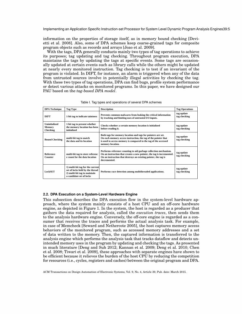
2.1. Understanding Tag-based DPA TechniquesTo understand the core features of various DPA techniques, it is noteworthy that pre-vious studies [Deng and Suh 2012; Chen et al. 2006; Chen et al. 2008] have alreadyanalyzed a number of the techniques whose characteristics [Devietti et al. 2008; New-some and Song 2005; Venkataramani et al. 2007; Clause et al. 2007; Zhou et al. 2007]are summarized in Table I. Note in the table that many techniques commonly main-tain and check the meta-data information, called tag, to describe the status of the hostprogram [Deng and Suh 2012] despite the differences in their types or granularities.For example, DIFT maintains a 1-bit tag to indicate whether a word/byte is from a po-tentially malicious sources [Newsome and Song 2005]. On the other hand, a tag maybe associated with a location such as a memory address instead of a value to keep
ACM Transactions on Design Automation of Electronic Systems, Vol. 9, No. 4, Article 39, Pub. date: March 2015.
Implementing an Application Specific Instruction-set Processor for System Level Dynamic Program Analysis Engines39:5
information on the properties of storage itself, as in memory bound checking [Devi-etti et al. 2008]. Also, some of DPA schemes keep coarse-grained tags for compositeprogram objects such as records and arrays [Joao et al. 2009].
With the tags, DPA generally conducts mainly two types of tag operations to achieveits purposes; tag updating and tag checking. Throughout program execution, DPAmaintains the tags by updating the tags at specific events. Some tags are occasion-ally updated at certain events such as library calls while the others might be updatedat nearly every monitored instruction. Tag checking is to test if an invariant of theprogram is violated. In DIFT, for instance, an alarm is triggered when any of the datafrom untrusted sources involve in potentially illegal activities by checking the tag.With these two types of tag operations, DPA can find bugs, profile system performanceor detect various attacks on monitored programs. In this paper, we have designed ourPAU based on the tag-based DPA model.
Table I. Tag types and operations of several DPA schemes
DPA Technique Tag Type Description Tag Operations
DIFT 1-bit tag to indicate taintness Prevents common malwares from leaking the critical informationby tracking and limiting uses of untrusted I/O inputs.
tag updatetag checking
Uninitialized Memory Checking
1-bit tag to present whether the memory location has been initialized
Checks whether a certain memory location is initialized before reading it.
tag updatetag checking
Bound Checking multi-bit tag to match the data and its location
Both tags for memory location and tags for pointers are set. On each memory access instruction, the tag of the pointer that is used to access memory is compared to the tag of the accessedmemory location.
tag updatetag checking
ReferenceCounter
multi-bit tag to store reference count for the data location
Performs reference counting to aid garbage collection mechanism. On an instruction that creates a new pointer, the tag is incremented. On an instruction that destroys an existing pointer, the tag is decremented.
tag updatetag checking
LockSET
1) multi-bit tag for the current set of locks held by the thread2) multi-bit tag to maintain a candidate set of locks
Performs race detection among multithreaded applications.tag updatetag checking
2.2. DPA Execution on a System-Level Hardware EngineThis subsection describes the DPA execution flow in the system-level hardware ap-proach, where the system mainly consists of a host CPU and an off-core hardwareengine, as depicted in Figure 1. In the system, the host is regarded as a producer thatgathers the data required for analysis, called the execution traces, then sends themto the analysis hardware engine. Conversely, the off-core engine is regarded as a con-sumer that receives the traces and performs the actual analysis task. For example,in case of Memcheck [Seward and Nethercote 2005], the host captures memory accessbehaviors of the monitored program, such as accessed memory addresses and a setof data written to the memory. Then, the captured information is transferred to theanalysis engine which performs the analysis task that tracks dataflow and detects un-intended memory uses in the program by updating and checking the tags. As presentedin much literature [Deng and Suh 2012; Kannan et al. 2009; Deng et al. 2010; Chenet al. 2008; Tiwari et al. 2009], these approaches with separate engines have shown tobe efficient because it relieves the burden of the host CPU by reducing the competitionfor resources (i.e., cycles, registers and caches) between the original program and DPA.
ACM Transactions on Design Automation of Electronic Systems, Vol. 9, No. 4, Article 39, Pub. date: March 2015.

39:6 I.Heo et al.
Instrumented Host Program Analysis TaskTrace Generation
Host CPU Hardware EngineExecution Trace
System Bus
Fig. 1. Execution model of system level hardware engine
As explained, in this execution model, the execution traces should be created andthen transferred to the analysis hardware. In the core-level approaches [Kannan et al.2009; Chen et al. 2006; Chen et al. 2008; Deng and Suh 2012], the traces are transpar-ently gathered with a dedicated hardware that observes the instructions executed bythe monitored program and creates the corresponding execution trace. On the otherhand, in the system-level approach [Tiwari et al. 2009], the host program is aug-mented with the code for trace generation so that a stream of traces is created bythe code on the host. Meanwhile, the analysis task on the hardware engine can beimplemented in the form of either hardware or software. In Hardgrind, the analysistasks of MemCheck [Seward and Nethercote 2005] and Helgrind [Savage et al. 1997]are implemented with specialized hardware modules like Range Cache [Tiwari et al.2008]. With the help of ASIC-style design, Hardgrind could achieve the speedups from29% to 440% in the two DPA techniques.
3. SYSTEM-LEVEL PROGRAMMABLE DPA ENGINE FOR EXTENDIBILITYIn this section, we will give an architectural overview including our hardware engineand discuss how DPA is performed on the proposed system. Also, we will discuss theefficient communication strategy between the host and our engine.
3.1. Overall System Design with PAUBased on the execution model of the system-level approach introduced in the previoussection, we designed our overall system which mainly consists of a host CPU and PAUas depicted in Figure 2 where PAU is connected via a general system bus to the hostCPU along with other modules including special purpose processors.In this work, ourSoC employs an AMBA-compliant system bus [Limited 1999] which is a shared busarchitecture conforming to the AMBA protocol, a de-facto standard for master-slavecommunication in modern SoC design. Hence, as long as our design obeys the AMBAprotocol, it can be used in every SoC based on AMBA protocol without any hardwarechange.
The key components of PAU are the tag processing core (TPC) and the main con-troller. TPC is a processor core of PAU which executes software codes. Its main task isto perform tag operations along the program execution flow running on the host andanalyze the monitored program. We will postpone the discussion of this task to Section4. The main controller manages all transactions related to the DPA computation. Itcontains configuration registers whose values can be changed to specify various typesof transactions. Thus, the host can control the action of PAU directly by setting theseregisters to certain values. To facilitate this control from the host, the configurationregisters are memory mapped.
The central role of PAU is the management of all the tags used for DPA. DuringDPA computation, all the tags being accessed are located in either PAU or the mainmemory. For every host processor register, TPC has a corresponding 32-bit tag, all of
ACM Transactions on Design Automation of Electronic Systems, Vol. 9, No. 4, Article 39, Pub. date: March 2015.

Implementing an Application Specific Instruction-set Processor for System Level Dynamic Program Analysis Engines39:7
InterruptOS KernelHost CPU
Configuration Commands
Memory Controller
GPU DSP
System Bus Interconnect
Slave IF Master IF
Tag Processing CoreTag Register File
Memory Access
HostProgram
Tag SpaceMain Memory
Main Ctrl.
Trace BufferTag Cache
PAU Inst. Cache
PAU
Fig. 2. The overall system design with PAU
which together form a single register file in TPC, called the tag register file (TRF).Since our host processor has 32 general registers, the TRF also consists of 32 entries.Since many DPA schemes augment tags to the registers, it is efficient to employ theTRF to support the tag-based DPA. Likewise, we allocate a space in the main memory,called tag space [Venkataramani et al. 2008], to manage various types of tags in thememory. This space is maintained by TPC throughout program execution to supportvarious types of tags which cannot be allocated in the TRF. Although such structureof memory tags might be a good way to support diverse tag types using the existingmemory architecture, it should be too slow if tags are frequently accessed from thetag space in the main memory. Therefore, to reduce the access latency, our PAU hasan internal SRAM, called tag cache [Kannan et al. 2009; Deng and Suh 2012], forcaching frequently referenced tags from the memory. In consequence, we would liketo emphasize that our design for tag management with TRF and tag cache intends toempower PAU supporting fast tag lookups.
Since our system is implemented as a SoC, we have integrated our PAU to the multi-processor SoC platform, strictly following a platform-based design methodology. Thereare two design criteria that we have endeavored to satisfy when following the method-ology for the development of our SoC hardware. First, we have tried to reuse as manyexisting modules as possible. They include various commodity IP cores, DDR mem-ory and shared interconnects through which every module in the system is attached.Second, we have forced newly added hardware modules to comply with all the speci-fications required by our target SoC platform. For instance, ARM regulates that anyIP module added to their platform obey the AMBA protocol. Therefore, in our imple-mentation based on the AMBA platform, the interface to our PAU conforms completelyto the AMBA protocol so that it can be connected to the host processor via the AMBAbus. In this sense, our solution differs from previous core-level approaches where theiracceleration modules are added and connected to processors via custom lines or inter-connects [Suh et al. 2004; Dalton et al. 2007; Kannan et al. 2009; Nagarajan et al. 2008;Chen et al. 2008]. Also, all special logics customized for DPA are fully integrated intoour PAU. This confirms our assertion that most hardware modules except the newlyadded PAU have been reused for our SoC implementation.
ACM Transactions on Design Automation of Electronic Systems, Vol. 9, No. 4, Article 39, Pub. date: March 2015.

39:8 I.Heo et al.
3.2. Execution Trace CommunicationNow, we will discuss how the execution traces are transferred from the host to PAUthrough the system bus. To buffer the difference between the times for handling theassigned tasks on the two processors, we have implemented a dedicated queue, calledthe trace buffer, in PAU. In fact, other solutions based on separate processing unitsusually also need queues [Chen et al. 2008; Nagarajan et al. 2008; Kannan et al. 2009;Deng and Suh 2012] for similar purposes. However, others are rather core-level ap-proaches thus demanding a change to the structure of their host CPU core or internalcaches to some degree. On the contrary, by placing the buffer outside the host CPU andconnecting it via a system bus, we preserve the original processor core architecture in-tact.
Figure 3 presents an example of the instrumented host code for a DPA method whichanalyzes the accessed memory addresses. It also displays the overall flow of tracetransactions via the trace buffer between the host code and TPC in PAU. In the ex-ample, note that two additional instructions, being marked with boldface, have beeninserted to the original code after instrumentation. They are added to generate twoexecution traces for memory addresses used by load/store instructions (traces #1 and#2). Suppose that the code is running on the host and reaches the code segment. Sinceld instruction (1) is executed, the corresponding memory address stored in register %i0should be gathered for DPA. As can be seen in the example, register %g4 is memory-mapped to the physical address of the trace buffer so that it provides a direct way tostore the trace in %i0 using st instruction (2). In a similar manner, a trace for memoryaddress used by instruction (6) is also pushed into the trace buffer with the instruction(7). Finally, the stored traces are consumed by TPC for actual analysis task.
….(1) ld [%i0], %g1(2) st %i0, [%g4] // Trace #1 : Load address is pushed.(3) add %g1, 3, %g1(4) sll %g1, 2, %o1(5) add %o1, %g1, %o1(6) st %o1, [%l1](7) st %l1, [%g4] // Trace #2 : Store address is pushed.…
TPC
Trace Buffer
NOTE : Register g4 is preset to the physical address of trace buffer.
Fig. 3. Execution trace communication
3.3. Synchronization and Multi-threading SupportIn general, the approaches with separate hardware engine for DPA including oursshould be able to handle the synchronization between the host CPU and the hardwareengine. In our approach, the trace buffer is used to minimize the overhead of synchro-nizing the data transactions among these processing units by buffering the traces gen-erated from the host, which helps the host continue its execution without being haltedfor the synchronization with PAU. However, such a basic synchronization mechanismbased on the trace buffer may create a potential loophole in security for some DPAtechniques that are to detect malicious attacks. For instance in DIFT, even if the hosthas just generated an important trace that is linked to a malicious activity, PAU maynot recognize the activity until the trace is extracted from the buffer for the analysisin PAU. If the buffer is already filled with many preceding traces, the adversary maysucceed in the attack long before PAU reaches the trace. To eradicate this loophole,
ACM Transactions on Design Automation of Electronic Systems, Vol. 9, No. 4, Article 39, Pub. date: March 2015.

Implementing an Application Specific Instruction-set Processor for System Level Dynamic Program Analysis Engines39:9
it would be necessarily required that the host CPU and PAU should be synchronizedat every instruction [Venkataramani et al. 2008]. However, as discussed in [Kannanet al. 2009; Garfinkel et al. 2004; Rajagopalan et al. 2006], such fine-grained synchro-nization may cause tremendous performance degradation in most cases. Thus in ourimplementation, the two computing units are synchronized at a more coarser granular-ity (i.e., at every system call), following the strategies of previous approaches [Kannanet al. 2009]. The rationale for this decision is due to the fact that many compromisedapplications usually exploit system calls. For example, when an attacker wants to leaksome sensitive data outside, the system call to open the network should be invoked. Inthis case, the data leak can be prohibited by checking the tag of data before sendingthe information through the network when DIFT keeps track of data flow during theruntime. Thus, we also utilize the system calls as an optimal granularity for synchro-nization in our architecture, to detect most malicious behaviors [Kannan et al. 2009],and yet to substantially lower the performance overhead.
In our prototype implementation, every time a system call is invoked on the host,the OS kernel informs PAU of the event by sending a configuration command to PAU,and stops the execution of the monitored program. For synchronization on each systemcall, the host sets the sync syscall register in the main controller. Once it is set, PAUconsumes all traces left in the trace buffer and then reports its status to the hostby sending an interrupt signal. Then, the host resumes its task after clearing thesync syscall register.
Another important synchronization point we should consider is the context switchbetween applications. On the host CPU, many applications with different contexts areconcurrently loaded. Thus, PAU should be notified of which process or thread is cur-rently executed on the host CPU. In our work, these critical events are also announcedto PAU by the OS kernel. Every time the OS scheduler is activated and a contextswitch occurs, the host notifies PAU this event by writing the current process ID andthe thread ID to the current PID and the current TID registers in the main controller,respectively. By doing so, PAU can identify the current process and thread ID on thehost.
4. TAG PROCESSING COREIn this section, we will explain the detailed design of TPU, the key component of ourPAU, which is a processor core that enables us to write the software code for the DPAtask in our approach. We will first describe the ISA of TPC whose mission is to supporta wide range of tag-based DPA techniques. Then, the microarchitecture of TPC will bediscussed.
4.1. TPC Instruction-Set ArchitectureBasically, the TPC ISA is extended from a simple RISC ISA so that the general struc-ture of software can be constructed with the ISA. Then, several types of instructionsare added to the ISA, which perform the specialized analysis operations that are com-monly inherent in the tag-based DPAs listed earlier. We will explain the data typeshandled by TPC and the types of instructions.
4.1.1. Data Types. In the TPC ISA, three types of data are supported to construct anal-ysis task software; (1) tag, (2) general and (3) execution trace. Many DPA techniquestypically associate a tag (that is meta-data) with each piece of state in the monitoredprogram [Deng and Suh 2012]. Thus, it is very natural to support the tag data typein our TPC design. Many details for the tag type were, in fact, discussed in Section 2.With the TRF and tag space in memory, TPC carries out a variety of tag operations toupdate and check the tags.
ACM Transactions on Design Automation of Electronic Systems, Vol. 9, No. 4, Article 39, Pub. date: March 2015.

39:10 I.Heo et al.
The general data type is necessary to construct a program structure for supportingtag operations. For example, to organize a loop structure that iterates the executionof a code segment for processing tags in an analysis code, there needs a set of data tocontrol loop iterations such as loop indices and temporary variables. To express thistype of supportive operations (e.g., loop iteration control) in the DPA algorithms, weprovide the general data type for our TCU ISA. In the analysis code, the operands ofthe general type are distinct from those of the other two types in a sense that they donot contain any analysis specific information like tags or execution traces. Therefore,they are stored in a separate register file, called the general register file (GRF). Duringcode execution, they must be loaded from memory to the GRF before being processed.
Lastly, the execution trace type is for the traces delivered from the host program. Asstated earlier, the execution traces which contain the runtime information of the hostare delivered to the analysis hardware engines such as our PAU. During the execution,TPC in PAU consumes the traces in order to follow the program execution flow andreceive runtime traces which are not determined at instrumentation time. We assignthe traces a different data type in order to distinguish the operations on them in thecode from those on the other types of data (i.e., general and tag). For this reason, atrace in the trace buffer in PAU is regarded as a data of the execution trace type,which is accessed by a specific set of instructions. For example, in DIFT, the results ofbranches and the memory addresses accessed by load/store instructions are deliveredto the trace buffer as the execution traces. In TPC, the traces are regarded as thedata of execution trace type and processed by the special instructions to recognize thebehaviors of the host. The further details will be given in the next subsection.
4.1.2. Instruction Types. To support the analysis tasks for DPA, we have designed fourtypes of instructions in our TPC ISA; (1) general, (2) tag ALU, (3) tag load/store and(4) trace handling. The first set of instructions corresponds to those in a RISC-styleinstruction set to organize general program structure. In fact, it is directly matchedto the general data type and gives our PAU the general programmability to constructanalysis task software. The general group includes general ALU operations, load/store,data movement and branches, as shown in Table II. They usually make use of GRF asthe operands for computation and access memory space to load/store data. In additionto them, there are several instructions newly added for data movement between GRFand TRF. For example, mov.tg instruction moves the data in TRF to GRF. Then, thetag value can be manipulated by general instructions for the purpose of analysis andwritten back to TRF with mov.gt instruction. These move instructions widen the wayto deal with the tags so that the degree of programmability in TPC ISA can also beimproved.
Many DPA schemes need to operate on the tags associated with processor regis-ters. Thus, for these types of operations, TPC ISA includes tag ALU instructions thatperform the operations among the register tags, as shown in Table II. These instruc-tions are functionally similar to the ALU instructions for the ordinary data except thattheir operands come from TRF. This type of instructions might be most frequently usedin analysis software because tag updating and checking are the kernel parts of mostDPAs.
On the other hand, in case of the tags located in tag space, they should be loaded tothe registers for computation. To access the tag space, two types of tag load/store in-structions are supported in TPC ISA. As given in Table II, the GRF and TRF load/storeinstructions take operands from GRF and TRF, respectively. In most cases, analysissoftware performs TRF loads/stores to propagate tags between registers and memorylocations. However, as in reference counting, DPA should update their tags located inthe tag space without interacting with TRF. In these cases, a GRF load or store is
ACM Transactions on Design Automation of Electronic Systems, Vol. 9, No. 4, Article 39, Pub. date: March 2015.

Implementing an Application Specific Instruction-set Processor for System Level Dynamic Program Analysis Engines39:11
Table II. Overview of TPC instruction-set
Instruction Type Sub-Type Instructions Example ActionALU/Data Movement add,sub,mov, … add R2,R3,R1 R1 = R2 + R3
load load [R2],#4,R1 R1 = Mem[R2+4]store store R2,[R1],#4 Mem[R1+4] = R2
Branch beq,bneq,jump, … beq #imm PC = PC+#immData Movement to TRF mov.gt mov.gt R1,T1 T1 = R1Data Movement to GRF mov.tg mov.tg T2, R2 R2 = T2Register-Register add.t,sub.t,and.t,xor.t, … xor T2,T3,T1 T1 = T2 xor T3Register-Immediate addi.t,subi.t,andi.t,xori.t, ... addi.t T1,#1,T1 T1 = T1 + 1
cmp.g cmp.g T1,R1 compare T1 with R1cmp.t cmp.t T1,T2 compare T1 with T2
GRF Load/Store load.g, store.g load.g [R2],R1 Mem[TLB(R2)] = R1TRF Load/Store load.t, store.t load.t [T2],T1 Mem[TLB(T2)] = T1
mov.bg mov.bg trace,R1 R1 = tracemov.bt mov.bt trace,T1 T1 = trace
Trace Compound ALU add.tc, sub.tc, or.tc, … add.tc trace,T2, T1 T1 = T2 + traceTrace Compound ALU/Load add.tcl, sub.tcl, or.tcl, .. or.tcl T2, [trace],T1 T1 = T2 | Mem[trace]Trace Compound ALU/Store add.tcs, sub.tcs, or.tcs, … or.tcs T1,T2,[trace] Mem[trace] = T1 | T2
GeneralLoad/Store
Tag ALU
Tag Load/Store
Trace Movement
Trace Handling
Tag Check
useful because it does not pollute the status of TRF which contains the meta-data forprocessor registers. It is noteworthy that the tag load/store instructions are differentfrom the ordinary load/store ones in that they use the tag TLB. In order to efficientlymanage tags in memory, PAU employs the tag TLB proposed in Harmoni [Deng andSuh 2012] that translates a data address to a tag address. By utilizing the specializedlogic, the tag load/store instructions can be performed with the low address translationoverhead.
Lastly, the execution traces from the host should be handled in PAU to follow theprogram execution flow. For this purpose, the trace handling instructions are provided.Recall that the traces are located in the trace buffer and accessed sequentially in order.In the trace handling instructions, the buffer is regarded as a register. To move a tracefrom the buffer to GRF/TRF, PAU supports two types of move instructions; mov.bgand mov.bt. The move instructions can be used when the trace should be further ma-nipulated or interpreted to extract the required information. Also, there are a set ofinstructions, called the compound instructions, which take a trace as an operand. Theysubstantially reduce the number of instructions to be executed when a trace from thebuffer is used as an operand in tag updating. For example, in DIFT, memory addressesof store instructions are transferred to PAU as execution traces. In this case, the tracewould be used as a destination operand in tag computations. If we would not havethe compound instructions, the computations should require five TPC instructions asfollows.
— instruction executed by the host : st [%g1], %g2— execution trace : address value in register %g1— tag propagation rule : Tag[Mem addr[%g1]] = Tag[%g1] | Tag[%g2]— DIFT analysis code in PAU :
(1) mov.bg R7 : trace movement to GRF (address in %g1)(2) mov.tg T1, R1 : tag movement from the TRF to GRF(3) mov.tg T2, R2 : tag movement from the TRF to GRF(4) or R3, R1, R2 : tag propagation to a temporary register(5) store.g [R7], R3 : update memory tags
A compound instruction, or.tcs, can substitute for the set of instructions. When it isexecuted, the address in the trace is used as a store address for tag space, and the tagsin the two registers (T1 and T2) are propagated to the memory tag, while it increases
ACM Transactions on Design Automation of Electronic Systems, Vol. 9, No. 4, Article 39, Pub. date: March 2015.

39:12 I.Heo et al.
the analysis performance. Because many analysis schemes tend to directly associatethe traces to their tags during execution, the instruction set is a good way to supportthem.
4.2. TPC MicroarchitectureIn this subsection, we will show the microarchitecture of TPC for the ISA design de-scribed in the previous subsection. Figure 4 represents the internal block diagram ofTPC. In order for TPC to launch tag computation, two preliminary conditions must bemet. First, the analysis code associated with the instrumented host code has been cre-ated and located in the main memory. Second, the host CPU has begun the host codeexecution and deposited execution traces into the trace buffer, as demonstrated in Fig-ure 3. As soon as a trace arrives, a notification signal is sent to TPC. Upon receivingthe signal, TPC reads trace entries one-by-one from the trace buffer.
Trace Buffer
DecodeBlock
Tag TLB
I‐cache
Tag
ALU
TRF
Memory TagWriteback
Tag Processing Core
MainController
T‐cache
GRF
MTF
Main Memory
AHB Slave IF
Fig. 4. TPC microarchitecture
In order to function as a programmable processor, TPC has many general compo-nents of RISC architecture with a three-stage pipeline: (1) fetch-decode, (2) execution,and (3) write-back. At the first stage, TPC code is loaded from the memory and de-coded by the decode block. Since main memory is normally implemented with externalDRAM devices, off-chip memory access latency can be a serious performance bottle-neck. To alleviate this problem, we have implemented the instruction cache betweenTPC and main memory.
At the next stage, TPC fetches operands from the two register files, and accesses thetag space with the tag TLB and the tag cache. At the same time, TPC schedules thememory tag fetcher (MTF) unit to fetch the tags in memory according to the memoryaddresses in the trace buffer, in order to support the trace compound instructions. Anoperand of the general type is also loaded from the main memory at this stage. Inour current prototype, there is no dedicated cache for the data of general type mainly
ACM Transactions on Design Automation of Electronic Systems, Vol. 9, No. 4, Article 39, Pub. date: March 2015.

Implementing an Application Specific Instruction-set Processor for System Level Dynamic Program Analysis Engines39:13
because the operations on general data are relatively few as being compared to theother types of operations. However, if a developer wants to cache a set of general data,it is also possible to map them to the tag space so that they can be cached in the tagcache. After all operands are ready, they are then forwarded to the tag ALU that takesthese tags as the operands to conduct tag computations or other general ones.
At the last stage, TPC updates the result back to either the register files or thememory space, depending on the executed TPC instruction. Just in case the tag cacheis updated with new data, we have implemented a write-through cache scheme in orderto keep the consistency of data stored both in this tag cache and the tag space insidemain memory. Once TPC has completed the execution of all instructions fetched andthere is no trace from the host, it will be idle waiting for new traces filled into thebuffer by the host. If not, it reiterates the normal execution procedure as described sofar.
5. CASE STUDIESThe programmability of the TPC ISA offers developers a good capability of imple-menting a variety of their DPA schemes with flexibility in software on our PAU. Inthis section, as case studies, we will discuss how several well-known DPA techniquescan be realized on our prototype as software codes that are composed of the TPC in-structions. As examples, we picked three techniques; DIFT [Newsome and Song 2005],uninitialized memory checking (UMC) [Venkataramani et al. 2007] and bound check-ing (BC) [Clause et al. 2007]. After briefly introducing the idea of each DPA scheme,we will discuss our DPA implementation on PAU.
5.1. Case Study 1 : DIFT for Data Leak Prevention5.1.1. Background of DIFT. To protect the confidential data inside computing devices,
an approach called data leak prevention (DLP) has been proposed. In the approach,security policies defining critical information and the corresponding actions (that is,deny/permit) on the specific output channels are forced to prevent any critical infor-mation from flowing into the outside of devices. A common way to realize DLP hasbeen to use DIFT [Yin et al. 2007; Enck et al. 2010], one of the widely used DPA tech-niques. This analysis scheme sets up rules to tag (or taint) internal data of interest andkeeps track of the taintness of their tags throughout the system [Kannan et al. 2009].At run time, every data derived from the one with tainted tag has its tag tainted. Analarm will be triggered as soon as any of the tainted data involves in potentially illegalactivities, such as pointing inside the code or being included in a data stream on theoutput channels [Enck et al. 2010].
When DIFT is employed for DLP, the first step is to tag or taint as sensitive the inputdata from sensitive sources like confidential files. Then, through code execution, thedata tags are then also propagated by tagging as sensitive the data derived from thosewith tainted tags, following the tag propagation rule of DIFT. If the code makes anunauthorized attempt to leak any of tainted data [Qin et al. 2006], a security exceptionwill be raised to announce the existence of data leak.
5.1.2. Tag Initialization and Check Procedures. As introduced, DIFT uses the tags to indi-cate the taintness of the data. To support the tag-based analysis in this case study, weassign a 1-bit tag for every host processor register and store it into our TRF in TPC.Each 1-bit assigned to a register in TRF represents whether or not the correspondingprocessor register currently holds sensitive data. Likewise, one bit is assigned for eachword in memory, and these bits are all arranged in the tag space, in a similar way tothat suggested in [Venkataramani et al. 2008].
ACM Transactions on Design Automation of Electronic Systems, Vol. 9, No. 4, Article 39, Pub. date: March 2015.

39:14 I.Heo et al.
In general, we can divide the tasks of DIFT for DLP into the three stages: tag initial-ization, propagation and check. In this study, the tag initialization and check stagesare executed by the OS kernel in the host processor. Depending on whether data orig-inates from a sensitive source, the kernel initializes its tag by setting the bit on or off.Just before data is transferred to an output channel, the kernel checks its tag to decideif the data transfer is safe. We will discuss the tag propagation stage later in order tofirst focus our discussion on these two stages which require a close interaction betweenthe kernel and PAU.
On a computing device, sensitive sources include GPS, files with confidential con-tents and SIM cards with private information. In specific, in this study, we focus onthe confidential files on the system as our sensitive sources and the kernel maintainthe list of them. To monitor every access of an application to any file in the system, wemodified open system calls in our Linux prototype system. When one of applicationsopens a file by invoking the system call, the kernel determines if the file is in the list.If so, the file pointer will be tainted by setting its bit on. For this tag initialization,the kernel function tag init is invoked. In our system on the host processor, the func-tion is implemented as a device driver interacting with our PAU. Its task is reportingto PAU the location (i.e., register number or memory address) of the data that mustbe tainted. Depending on its type, the location is written to either source taint reg orsource taint addr, both of which can be configured via changing the values of memory-mapped configuration registers in the main controller of PAU. Then PAU responds thereport from the kernel by tainting the tag for the location.
For the tag check stage, we also have embedded a new function tag checking into thesystem calls involved in network packet generation. When data is about to be trans-ferred outside as a network packet through an output channel, this kernel functionchecks the data tag with the assistance of PAU. As the first step of this check, thefunction writes the data location into either sink taint reg or sink taint address in theconfiguration registers, similarly to the tag initialization stage. Then it sends to PAUthe inquiry of the current tag value at this location. Upon receiving the inquiry, PAUretrieves the value from either TRF or tag cache, and interrupts the host to notify theresult back to the kernel. Now the kernel knows whether or not the data of interest isfrom sensitive sources.
5.1.3. Tag Propagation. As explained in Section 2, in our approach, the time-consumingpart of DPA is delegated to PAU to relieve the burden of the host processor and it cor-responds to the tag propagation computations in DIFT for DLP. To carry out the propa-gation task on our PAU, TPC code includes propagations rules and operands extractedfrom the original program run on the host processor. When our in-house instrumenttool generates the code, most required information like register operands can be stat-ically extracted and embedded in the generated code. But some dynamic informationthat can only be resolved during code execution is still missing in the generated code.In our DIFT implementation, such information includes (1) an execution path of theoriginal program and (2) memory addresses of load/store instruction. Currently, thismissing information is supplemented and sent as execution traces at run time by thehost processor to PAU, hence helping PAU have the enough information to track tagpropagation at any circumstance.
Figure 5 shows a segment of the original program in (a), its associated pseudo prop-agation code in (b) and the realized TPC code in (c). As can be seen from (b), a pseudoinstruction is comprised of a propagation rule and operands. They are to specify the se-mantics of tag propagation by the matching instruction in (a). For instance, the thirdDIFT instruction in (b), which is parallel to the sll instruction in (a), has ”%o1 and%g1” as operands and “copy from the right tag to the left” as a rule. When the original
ACM Transactions on Design Automation of Electronic Systems, Vol. 9, No. 4, Article 39, Pub. date: March 2015.

Implementing an Application Specific Instruction-set Processor for System Level Dynamic Program Analysis Engines39:15
instruction is executed, so does the pseudo instruction and thus if the tag of %g1 istainted, %o1’s tag will also be tainted because of the ‘copy’ tag propagation rule.
Original Codeld [%i0], %g1add %g1, 3, %g1sll %g1, 2, %o1add %o1, %g1, %o1st %o1, [%l1]
Pseudo Propagation Codetag[%g1] = tag[%i0] or tag[mem_addr[%i0]]tag[%g1] = tag[%g1]tag[%o1] = tag[%g1]tag[%o1] = tag[%g1] or tag[%o1]tag[mem_addr[%l1]] = tag[%o1] or tag[%l1]
(a) (b)
TPC Codeor.tcl T1,[trace],T24(unnecessary)mov.t T1,T9or.t T9,T1,T9or.tcs T9,T1,[trace]
(c)
Fig. 5. A TPC code example for DIFT computation
In the analysis task of PAU, the propagation rules are expressed by the TPC in-structions as given in Figure 5 (c). For two load/store instructions in the host code,the propagations are processed by the compound instructions since they make use ofthe trace in the trace buffer to figure out the location of tags. As seen in this exam-ple, our compound instruction can reduce the number of instructions required for thetrace handling. For the other ALU operations in the host, the tag ALU instructions areused to propagate the tags between the tag registers. However, for the second instruc-tion add, the corresponding TPC instruction is omitted because it does not change thetag status of PAU. In our software implementation, we have made efforts to removethese unnecessary propagation operations, being empowered by the programmabilityof TPC. The TPC codes are generated by our in-house instrument tool and allocated toTPC code memory region before the execution.
During the host program execution, PAU expects execution traces from the hostprocessor to compensate for the missing dynamic information that is indispensable forcorrect operation. The load/store addresses can be easily gathered into a trace sincethey are readily computable from the host program at run time. As for the executionpath, we may express it with a set of basic blocks and edges that connect them. Thus inour implementation, we assign every basic block a unique identification (ID) number,and during code execution, let the host processor deliver the ID of a block to PAU so asto pinpoint the exact block that the host execution path currently comes to.
As seen in Figure 1, the original program installed on the host has to be instru-mented to enable communication with PAU for orchestrating analysis operations inour solution. Figure 6 presents an example of the instrumented host code generatedfrom the original one in Figure 5. It also displays the overall flow of trace transactionsfor DIFT via the trace buffer between the host code and TPC. In the example, notethat four additional instructions, being marked with boldface, have been inserted tothe original code after instrumentation. They are added to generate three traces, onefor the current basic block information (trace #0), and two for memory addresses usedby load/store instructions in the same block (traces #1 and #2). Suppose that the codeis running on the host and the execution path comes to this block LL5. Then, movinstruction (1) is first executed to initialize register %g3 with the basic block ID. Ascan be seen in the example, register %g4 is memory-mapped to the physical addressof the trace buffer, thereby providing a direct way to store the trace in %g3 using stinstruction (2). In a similar manner, traces for memory addresses in the basic block arealso pushed into the trace buffer with the instructions (4) and (9). The stored tracesare consumed by TPC for tag propagation.
In order to conduct the analysis task for DIFT with the basic block ID, we decom-posed the TPC code into multiple regions, each containing a single basic block of TPCinstructions, as Figure 7 depicts. Each region includes a header for its basic block.
ACM Transactions on Design Automation of Electronic Systems, Vol. 9, No. 4, Article 39, Pub. date: March 2015.

39:16 I.Heo et al.
.LL5:(1) mov 0x5, %g3 // Basic Block ID : 5(2) st %g3, [%g4] // Trace #0 : Basic Block ID (3) ld [%i0], %g1(4) st %i0, [%g4] // Trace #1 : Load address is pushed.(5) add %g1, 3, %g1(6) sll %g1, 2, %o1(7) add %o1, %g1, %o1(8) st %o1, [%l1](9) st %l1, [%g4] // Trace #2 : Store address is pushed.
TPC
Trace Buffer
NOTE : Register g4 is preset to the physical address of trace buffer.
Fig. 6. Execution trace communication for DIFT
The basic block header holds the useful information for PAU (e.g., the number of TPCinstructions and the number of load/store). At the beginning of the TPC code region,there is a lookup table, called the basic block jump table, which is used to access everybasic block in the TPC code. During execution, when TPC receives a trace indicatinga basic block ID, it accesses the basic block jump table. Then, it jumps to the addressand finds the TPC instructions within this basic block. After finishing the block, TPCwill find another trace in the buffer and continues the analysis if the buffer has one.
...
Basic Block n JUMP ADDR.
Basic Block n+1 JUMP ADDR.
...
Basic Block n Header
TPC Instruction 0
TPC Instruction 1
...
TPC Instructions for Basic Block n Region
TPC Code Layout
@Basic Block n JUMP ADDRThe number of TPC instructions,Architecture-dependent information...
Tag propagation rule and operandsex) tag[r0] ← tag[r1] | tag[r2], ...
Basic Block Jump Table
Fig. 7. TPC code layout
5.2. Case Study 2 : Uninitialized Memory Checking5.2.1. Background. As the second implementation example of our case study, we chose
UMC which was firstly proposed in [Venkataramani et al. 2007]. The objective of thisDPA technique is to detect a read access to the memory region where initialization isnot performed yet. Since the read event to an uninitialized location causes a memoryerror which is often exploited by attackers as a security hole, it is vital to detect andremove such cases in program execution for security purposes [Venkataramani et al.2007].
In Figure 8, we depict the state transition diagram of the UMC scheme to explainthe principle of the DPA. As explained in Table I, UMC augments an 1-bit tag forevery word in memory to indicate whether the corresponding location is initialized ornot. When the system is reset, every memory location is assumed to be uninitialized.If a value is stored to a certain memory location, the state of the location is transitedfrom Uninitialized to Initialized as shown in Figure 8. Once a memory location entersthe Initialized state, both load and store operations from/to the location are permitted. However, any load access to a location with Uninitialized will be called an error. Now
ACM Transactions on Design Automation of Electronic Systems, Vol. 9, No. 4, Article 39, Pub. date: March 2015.

Implementing an Application Specific Instruction-set Processor for System Level Dynamic Program Analysis Engines39:17
let us explain how this memory checking model can be mapped to the tag-based DPAusing PAU.
Uninitialized Initialized
Load or StoreRead from
Uninitialized Memory
Load
Store
Fig. 8. State transition diagram for UMC
5.2.2. UMC Implementation. To carry out UMC on PAU, we assign a 1-bit tag for everyword in the application memory region and store the set of tags into the tag space inthe main memory. As explained above, the tasks of UMC are mainly divided into twoparts; tag initialization and check. In our UMC implementation, both the operationsare composed of TPC instructions with the execution traces delivered from the host asinput. For every memory write on the host, the write address is transferred to TPCfrom the host. Then, the tag corresponding to the address is set to ‘1’ in order to in-dicate that the location is initialized. This is the tag initialization process. Likewise,when the host reads a memory location, the address is also delivered to TPC. At thismoment, TPC checks the value of the corresponding tag and if it is not ‘1’ (i.e., Unini-tialized), an exception is raised to inform the host of an unallowable memory access.
Figure 9 illustrates a segment of the original example program in (a), its associatedpseudo UMC code in (b) and the implemented TPC code in (c). When the original codeis executed on the host, TPC code also runs in parallel to check whether the memoryaccess rule enforced by UMC is violated or not.
For each load instruction in the host code, the tag check is performed by three TPCinstructions. At first, a compound instruction, “mov.tcl” is used to read a trace in thetrace buffer which contains the accessed address and load the memory tag correspond-ing to it. Then, a comparison between the memory tag and the register R1 is performedby the “cmp.g” instruction. To mark the Initialized state, the register R1 is set to ‘1’.Thus, if the comparison between the tag and R1 produces the “not equal (ne)” con-dition, it implies that the load instruction attempts to read an uninitialized memorylocation. For these cases, according to the rule of UMC, TPC jumps to an exception rou-tine to trigger an alarm by sending an interrupt to the host. In this example, the labelfor the routine is named as “trigger alarm”. On the other hand, for each store instruc-tion in the host code, the tag initialization is performed by the mov.tcs instruction. Inour example, the register T2 is also preset to ‘1’ to indicate the Initialized state. Bywriting the value (i.e., 1) to the memory tag of the delivered address, TPC carries outthe tag initialization process.
5.3. Case Study 3 : Bound Checking5.3.1. Background. As the last implementation example, we chose BC, which is a DPA
technique proposed in [Clause et al. 2007]. The objective of this scheme is to checkwhether or not each memory operation with a pointer accesses the location within the
ACM Transactions on Design Automation of Electronic Systems, Vol. 9, No. 4, Article 39, Pub. date: March 2015.

39:18 I.Heo et al.
Original Codemov #0x74, %i0ld [%i0], %g1mov #0xffff, %o1st %o1, [%i0]
Pseudo Tag Initialization and Check Code(unnecessary)if (tag[mem_addr[%i0]]!=1) trigger_alarm(unnecessary) tag[mem_addr[%i0] = 1
(a) (b)
TPC Codemov.tcl [trace],T1cmp.g T1,R1bne trigger_alarmmov.tcs T2,[trace]
(c)
NOTE : Register R1 in (c) contains the value ‘1’.NOTE : Register T2 in (c) contains the value ‘1’.
Fig. 9. A TPC code example for UMC computation
legitimate range allocated by the program for the pointer. If it ever makes an out-of-bound access, BC reports the access as a memory error since it can be exploited as asecurity vulnerability.
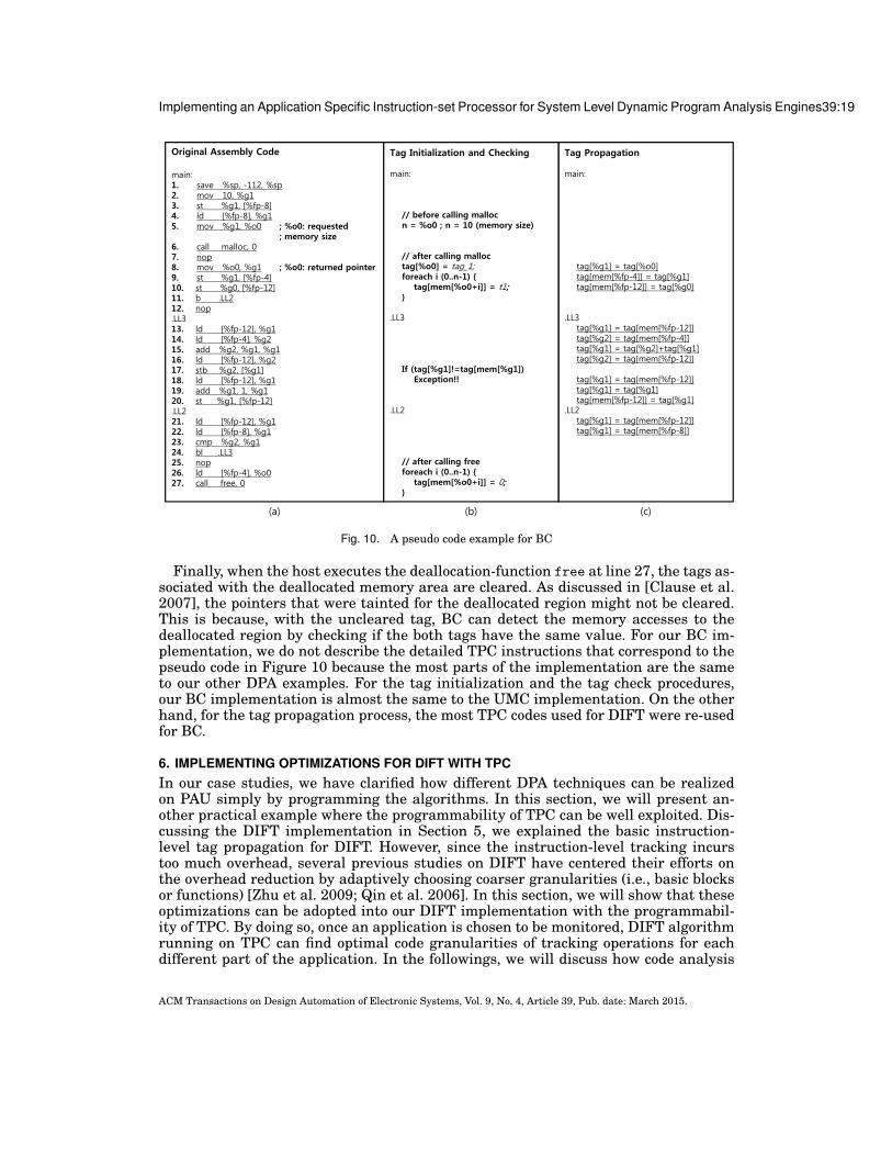
The tasks of BC can be divided into three stages; tag initialization, propagationand check. To perform the procedure, BC augments the tags for both pointers andcorresponding memory locations [Deng and Suh 2012]. Whenever a memory region isallocated at runtime, BC initializes the tags for both the memory locations and thepointer to the starting address. In a high-level language like C/C++, special functionsare provided for memory allocation, such as malloc. They usually take the size of therequested memory as input and return the starting address of the allocated region.Every time the functions perform their task, BC identifies the range of the allocatedmemory in the form of “[p, p+size)”, where p is the starting address returned and sizeis the size of the allocated region [Clause et al. 2007]. Then, BC assigns the same tagvalue to both the tags of the allocated memory locations and the tag of the registerwhich contains the returned pointer.
During the execution, the pointer tag is propagated to the other storage locationin accordance with the propagation rule of BC [Clause et al. 2007]. On each memoryinstruction such as load or store, the register tag for the pointer is compared with thetag of the accessed memory region. Obviously, the two tags must be identical for in-bound accesses but different for out-of-bound accesses [Clause et al. 2007]. Therefore,only when the tags are identical, the memory access will be granted. Otherwise, BCreports the memory error.
5.3.2. BC Implementation. To implement BC in this study, we assign 4-bit tags for mem-ory locations and pointers as in [Deng and Suh 2012]. In Figure 10, we depict the hostcode in assembly level in (a), the pseudo tag initialization/check code in (b), and thepseudo tag propagation code in (c). In (a), a memory-allocation function, malloc, isinvoked at line 6. The parameter of the function is the size of the requested memoryand set at line 5 (in register %o0). After the malloc allocates the memory region, thestarting address for the region is written to the register %o0 according to the callingconvention. At this time, the host transfers two traces to the TPC; the size of the regionand the value of the pointer. Then, TPC performs the tag initialization which assignsthe same tag values to the tags for the allocated memory region and the tag for thecorresponding register %o0 as shown in (b).
After that, during execution, the pointer tag is propagated to other registers or mem-ory locations as shown in (c). The tag propagation rule of BC is almost the same to thatof DIFT. Then, when the host attempts to access the allocated memory at line 17, withthe delivered trace which contains the accessed address, TPC checks whether or notthe tag of the pointer (the tag for %g1) is matched to the tag of the accessed memorylocation. If the both tags do not match, an exception is raised and the interrupt to thehost is triggered.
ACM Transactions on Design Automation of Electronic Systems, Vol. 9, No. 4, Article 39, Pub. date: March 2015.
Implementing an Application Specific Instruction-set Processor for System Level Dynamic Program Analysis Engines39:19
Original Assembly Code
main:1. save %sp, -112, %sp2. mov 10, %g13. st %g1, [%fp-8]4. ld [%fp-8], %g15. mov %g1, %o0 ; %o0: requested
; memory size 6. call malloc, 07. nop8. mov %o0, %g1 ; %o0: returned pointer9. st %g1, [%fp-4]10. st %g0, [%fp-12]11. b .LL212. nop.LL313. ld [%fp-12], %g114. ld [%fp-4], %g215. add %g2, %g1, %g116. ld [%fp-12], %g217. stb %g2, [%g1]18. ld [%fp-12], %g119. add %g1, 1, %g120. st %g1, [%fp-12].LL2 21. ld [%fp-12], %g122. ld [%fp-8], %g123. cmp %g2, %g124. bl .LL325. nop26. ld [%fp-4], %o027. call free, 0
(a)
Tag Propagation
main:
tag[%g1] = tag[%o0]tag[mem[%fp-4]] = tag[%g1]tag[mem[%fp-12]] = tag[%g0]
.LL3tag[%g1] = tag[mem[%fp-12]]tag[%g2] = tag[mem[%fp-4]]tag[%g1] = tag[%g2]+tag[%g1]tag[%g2] = tag[mem[%fp-12]]
tag[%g1] = tag[mem[%fp-12]]tag[%g1] = tag[%g1]tag[mem[%fp-12]] = tag[%g1]
.LL2tag[%g1] = tag[mem[%fp-12]]tag[%g1] = tag[mem[%fp-8]]
(b)
Tag Initialization and Checking
main:
// before calling mallocn = %o0 ; n = 10 (memory size)
// after calling malloctag[%o0] = tag_1;foreach i (0..n-1) {
tag[mem[%o0+i]] = t1;}
.LL3
If (tag[%g1]!=tag[mem[%g1])Exception!!
.LL2
// after calling freeforeach i (0..n-1) {
tag[mem[%o0+i]] = 0;}
(c)
Fig. 10. A pseudo code example for BC
Finally, when the host executes the deallocation-function free at line 27, the tags as-sociated with the deallocated memory area are cleared. As discussed in [Clause et al.2007], the pointers that were tainted for the deallocated region might not be cleared.This is because, with the uncleared tag, BC can detect the memory accesses to thedeallocated region by checking if the both tags have the same value. For our BC im-plementation, we do not describe the detailed TPC instructions that correspond to thepseudo code in Figure 10 because the most parts of the implementation are the sameto our other DPA examples. For the tag initialization and the tag check procedures,our BC implementation is almost the same to the UMC implementation. On the otherhand, for the tag propagation process, the most TPC codes used for DIFT were re-usedfor BC.
6. IMPLEMENTING OPTIMIZATIONS FOR DIFT WITH TPCIn our case studies, we have clarified how different DPA techniques can be realizedon PAU simply by programming the algorithms. In this section, we will present an-other practical example where the programmability of TPC can be well exploited. Dis-cussing the DIFT implementation in Section 5, we explained the basic instruction-level tag propagation for DIFT. However, since the instruction-level tracking incurstoo much overhead, several previous studies on DIFT have centered their efforts onthe overhead reduction by adaptively choosing coarser granularities (i.e., basic blocksor functions) [Zhu et al. 2009; Qin et al. 2006]. In this section, we will show that theseoptimizations can be adopted into our DIFT implementation with the programmabil-ity of TPC. By doing so, once an application is chosen to be monitored, DIFT algorithmrunning on TPC can find optimal code granularities of tracking operations for eachdifferent part of the application. In the followings, we will discuss how code analysis
ACM Transactions on Design Automation of Electronic Systems, Vol. 9, No. 4, Article 39, Pub. date: March 2015.

39:20 I.Heo et al.
information is applied to help our DIFT implementation to adaptively choose optimalgranularities for tag propagation within individual basic blocks or functions such thatdata leaks can be prevented while computation overheads are minimized. We will alsodescribe how our PAU supports multi-level tag propagation efficiently in hardware.
In an attempt to choose optimal granularities for tag propagation within an appli-cation, we first divide application code into functions of three categories as follows,referring to the prior researches on DIFT [Qin et al. 2006; Zhu et al. 2009]:
1. Their output tags are independent of input tags.2. Their tag propagation behaviors are known a priori and so summarized in a
well-defined form.3. None of the above.
For categories 1 and 2, tag propagation can be optimized by either skipping the com-putation completely or doing efficient function-level computation with only a few TPCinstructions and execution traces, thus relieving the computation loads from PAU. Forthe last category, exhaustive finer-grained computations are inevitable since intensivemonitoring is mandatory due to the nature of these functions. Fortunately in our DIFTimplementation, we can still hinge the optimization of these heavy computations onour PAU which helps us not only to accelerate instruction-level computation but alsoto enjoy faster block-level computation for some parts of the functions in this cate-gory. In the followings, we will discuss our optimization strategies according to thesecategories.
6.1. Function Level Tag Propagation OptimizationGiven a function of category 1 or 2, the whole tag propagation can be virtually turnedoff even though a small number of TPC instructions along with traces still need to beexecuted to fulfill complete tag propagation for those in category 2. Since huge perfor-mance gain can be obtained via function-level tag propagation, we try to maximize itby classifying as many functions as possible into categories 1 and 2 during our offlinebinary translation. This classification can be done by adopting traditional static anal-ysis [Zhu et al. 2009; Saxena et al. 2008]. Another way to achieve it might be collectinga list of highly utilized functions encountered in applications such as library functionswhose semantics are also well known and defined. For this purpose, we profiled a set ofreal programs in order to choose such functions that consume most time in them. Whena function is found to be of category 1 or 2, we construct a function summary whichis composed of the function name, TPC instructions and the code for execution tracesthat will be added to the original binary for the function. These summaries are createdinto the function summary table (FST). During binary translation with the originalapplication, every function name in the code is brought to see if any function summaryin FST has the name. If so, our instrument tool uses the information in the summaryto produce the optimized TPC code as well as the host code that is instrumented togenerate execution traces.
We present a code example in Figure 11 to explain in more detail how our adaptivemulti-level DIFT is applied. Figure 11 (a) shows the original application code, wherethe invocation to the malloc function at line (3) takes the size as an input and returns apointer to the allocated memory space as the output. A simple analysis on this functionmay easily reveal that the output tags cannot be derived from the input one becausethe resulting pointer and memory locations are not data dependent on the input size.As a consequence, the function should belong to category 1 by definition, and so itsname has to be found in FST. As shown in the example, we see that our instrumenttool produces neither code for traces nor for DIFT to save our computing resources,according to our optimization policy.
ACM Transactions on Design Automation of Electronic Systems, Vol. 9, No. 4, Article 39, Pub. date: March 2015.

Implementing an Application Specific Instruction-set Processor for System Level Dynamic Program Analysis Engines39:21
Fig. 11. An example for adaptive multi-level tracking
We assume that the function foo at line (7) is of category 2. Then, we can applyfunction-level DIFT to the function, as we explained. Therefore, small numbers of ex-ecution traces and TPC instructions are enough for complete tag propagation withinfoo. The figure shows that our instrument tool generates only two traces and four TPCinstructions referring to FST. Figure 11 (b) and (c) respectively depict execution tracesand TPC instructions generated after the multi-level tracking optimizations. Now no-tice that, in (b) for foo, the function ID is assigned in the first entry of the trace buffer.Similarly to basic block IDs in Section 5, a function ID is used to point PAU at theposition where its TPC code starts to execute.
The shaded regions in Figure 11 represent the function-level tag propagation forthe functions of categories 1 and 2. This clearly assures our argument that function-level optimizations improve the performance of both the host processor and PAU bydrastically reducing or eliminating the computation loads due to execution traces andTPC instructions.
6.2. Block Level Tag Propagation OptimizationAlthough function-level tag propagation has a great affirmative impact on perfor-mance, all functions cannot take such benefits. Not surprisingly in real applications,a majority of functions fall into category 3. In principle, these functions necessitateinstruction-level propagation, which will slow down the processing speed. To miti-gate the overhead and further improve the DIFT performance, we exercise a coarser-grained tag propagation on some basic blocks dynamically during code execution. Theoptimization technique on block level was proposed in LIFT [Qin et al. 2006]. The basicidea is that the whole tag propagation in a basic block can be safely precluded if all thelive-in/out rags of registers and memory locations into/from the block are untainted(i.e., the tag bits are all set off) at the boundary of the basic block. In LIFT, the decisionis made just before the host CPU enters the entry of each block at run time.
In our work, we also implement and apply the same optimization scheme on ourDIFT. The main difference between ours and LIFT is that the decision for every basicblock is performed by PAU in our work. Consequently, this makes the host CPU to beliberated from the decision task, which otherwise slow down the host performance dueto the computation overhead required for the task (e.g., instructions for managing and
ACM Transactions on Design Automation of Electronic Systems, Vol. 9, No. 4, Article 39, Pub. date: March 2015.

39:22 I.Heo et al.
checking the relevant tags, context switches for preserving the host program’s states).That is, whether or not a basic block satisfies the above conditions, the host proceedswith its normal execution of the instrumented binary for this block, as described inSection 5. At the same time, TPC would extract from the trace buffer the executiontraces that were issued from the host at the beginning of the current block. Recall thatwhenever TPC enters a new basic block, it reads the block ID from the first trace toexecute the TPC instructions in the block. At this moment, it will examine all live datatags crossing the block boundary. If none is tainted, TPC just skips the execution ofthis block and be ready to extract new execution traces for the next block as directedby the host.
To enable this block-level optimization, we need to collect a summary about livetags around each block. For this, we have augmented our instrument tool to supportlive range analysis that identifies the live register tags coming into/out of every basicblock, and puts them into the live list attached to each block. Assuming that nr isthe total number of registers, the live list is a bitmask of the size nr bits. If a bit isset to 1, this represents that the corresponding register tag is alive at the entry ofthe basic block. By simply reading this list, TPC can determine the liveness of allregister tags with ease. Contrary to the case of register tags, we do not apply staticanalysis to identify the live tags of memory locations obviously because exact memoryaddresses referenced in the code cannot be statically known in most cases. Thereforein our system, TPC collaborates with the host to dynamically figure out the liveness ofmemory tags at run time. To attain this objective, it accepts from the host all memoryreferences in a basic block through the trace buffer.
Figure 12 displays a small decision logic that is vital to TPC’s taint check of eachlive register or memory tag, which in turn collectively leads to the final decision onthe applicability of block-level optimization to the current block. This logic determineswhether live register tags are tainted or not by performing bitwise AND operationbetween the live list from the TPC code and the contents of TRF which is also an nr-bitbitstream of tags of registers. If the result of this operation is zero, all the live registertags are untainted. Live memory tags should also be considered by accessing the tagcache with the addresses stored in the trace buffer. As shown in Figure 11, the numberof memory addresses to be handled in the block is delivered as the execution trace(basic block ID and the number of memory addresses are encoded to a word). Thus,TPC can know how many memory tags should be considered for the decision. Since thetag cache has a single read port, it may take multiple cycles to load all memory tagsdepending on the number of memory addresses in the trace buffer. Finally, if all the livetags are declared untainted, TPC bypasses time-consuming instruction-by-instructiontag propagation inside the block, just waiting for the next direction from the host.
In Figure 11, we can see an example of block-level tag propagation within the func-tion bar. Let us assume that bar is of category 3. Then, this function would not befound in FST as defined earlier. Instead, the instrument tool generates the TPC codein which the live list for each basic block in bar is attached to its entry. The tool alsoproduces an instrumented code that will run on the host. Suppose that the host isabout to execute the basic block BB3 at line (11). At that time, TPC is ordered to ex-ecute the TPC code at the same line. As the first step, TPC has to extract the live listfrom the code, which is a bitmask 11010010 in this example. Then, it will compare itwith the contents of TRF shown in Figure 11 (d). Simultaneously, the memory tag ataddress 0x20000000 is also retrieved from the tag cache shown in Figure 11 (e). Wecan successfully verify that all the tags are untainted in this example. This means thatthe entire tag propagation in the basic block can be safely omitted. Figure 11 exhibitsthat all TPC instructions for the block BB3 are crossed out to indicate that the entirecode execution on TPC is bypassed. This example shows that our block-level optimiza-
ACM Transactions on Design Automation of Electronic Systems, Vol. 9, No. 4, Article 39, Pub. date: March 2015.

Implementing an Application Specific Instruction-set Processor for System Level Dynamic Program Analysis Engines39:23
tion can enhance the DIFT performance with the cooperation of software analysis andhardware support.
BB Header
Live list
DIFT Instruction #0
DIFT Instruction #1
DIFT Code
AND
Tag RegFile
32
32
Value!= 0 ?
32 1OR
BB Number
Memory Address #0
Memory Address #1
…
Memory Address #(N-1)
Trace Buffer
32
Tag Cache
Loading memory tags takes N cycles.
…
1OR
Cumulative Reg
1
1
1
Flag for Decision0, exit1, continue
Fig. 12. The decision logic for block-level optimization
7. EXPERIMENT7.1. Prototype SystemTo evaluate our approach, we have developed a full-system FPGA prototype, wherethe host processor is the SPARC V8 processor, a 32-bit synthesizable core [Manual2004] which uses a single-issue, in-order, 7-stage pipeline. It has separate 16K-byte2-way set associative instruction and data caches. The trace buffer has been imple-mented to accommodate at most 64 execution traces (i.e., 64x32bit) passed from thehost. The architecture of our PAU follows the description in Section 3 and 4. It hasthe tag cache which is a 512-byte, 2-way set-associative cache with 8-byte cache lines,and the instruction cache which is a 4K-byte, 2-way set-associative cache with 32-bytecache lines. The bus compliant with AMBA2 AHB protocol [Limited 1999] is used tointerconnect the all modules in our prototype system. Linux 2.6.21.1 is used as our OSkernel and a small portion of it has been modified to provide supports for our hardwareengine as described before. Based on the parameters for the prototype as describedabove, we synthesized our DPA engine and verified it on a FPGA prototyping boardwith a Xilinx XC5VLX330 FPGA and 64MB external SDRAM.
7.2. Synthesis ResultsWhen our hardware engine is employed in the systems that have severe resource con-straints such as mobile devices, the area and power budgets of PAU are also strictlylimited. Thus, in the systems, the area/power efficiency of the hardware engine is theforemost priority. In order to assess the area efficiency of our PAU, we quantified the re-sources necessary for PAU including the tag cache, instruction cache and trace buffer,in terms of gate counts using Synopsys Design Compiler [Guide 2009] with a com-mercial 45 nm process library. In Table III, the number of gates required for eachcomponent of PAU is described and compared to those of the baseline system includingthe host processor. The total area overhead for PAU is about 14.47%, as compared tothe baseline system. Considering that our host processor is a very small SPARC RISCprocessor, we assure that the area overhead for PAU is not critical to be deployed inthe commercial platforms.
ACM Transactions on Design Automation of Electronic Systems, Vol. 9, No. 4, Article 39, Pub. date: March 2015.

39:24 I.Heo et al.
As shown in the table, PAU can be divided into four parts; the components for tagcomputation which might correspond to the DPA engines in the hardware only ap-proach [Deng and Suh 2012], the components added for the programmability, the tracebuffer and the remaining parts such as AHB interface and interrupt generator. To sup-port a wide range of DPA schemes with the programmability, PAU requires additionalresources as described in the table (especially for the I-Cache). Although the amountof resources seems to be substantial, the total area overhead of PAU is not so huge asstated above.
To estimate the power consumption of PAU, we simulated our framework on Mod-elsim [Graphics 2007] and run the power estimation tools in Synopsys Design Com-piler [Guide 2009] using the simulation result as an input vector. As a result of ex-periment using a commercial 45 nm process library, the power consumption of PAU isestimated to be 224.2 mW at 1 GHz operating clock frequency. Since it is acceptablysmall when compared to the power consumption of SPARC host processor (940 mWat 1 GHz), our PAU can be deployed in the commercial SoC platforms which have thelimited power budget.
Table III. Synthesis result
Category Component Gate CountsSPARC V8 Core (Host Processor) 1761079.777Bus components (AHB Buses + AHB/APB bridges) 2137.61Memory Controller 3812.52Peripherals (TIMER, UART, and etc.) 3304.15Total Baseline System 1770334.057Tag Register File (TRF) 957.4992Decoder 2305.6902Tag Cache 13253.2245Tag ALU 4932.274Tag TLB 10266.833Total Resources for Tag Compuation 31715.5209General Register File (GRF) 950.1425Main Controller 1339.0524Memory Tag Fetcher (MTF) 13253.2245I-Cache 203811.3338Total Resources for Programmability 219353.7532Trace Buffer (16 x 32-bit) 3425.1589ETC (including AHB Slave Interface) 1683.0324Total Resources for PAU 256177.4654% PAU over Baseline System 14.47%
BaselineSystem
PAU
7.3. Performance EvaluationWe have measured the performance improvement of our hardware engine overthe previous approaches by choosing applications from the mibench benchmarksuite [Guthaus et al. 2001] and comparing in performance with the four configura-tions. In this experiment, the configuration NC stands for native code which executesthe original codes on the host CPU with DPA disabled. This is used as baseline, andall the other configurations are set with DPA enabled. For SWD, not only the code oforiginal program but also the code for DPA are executed on the host core. Thus, when-ever the DPA procedure is needed at a certain point of the program, the host invokes
ACM Transactions on Design Automation of Electronic Systems, Vol. 9, No. 4, Article 39, Pub. date: March 2015.

Implementing an Application Specific Instruction-set Processor for System Level Dynamic Program Analysis Engines39:25
the function which performs the tag computations. For MPD, to improve the perfor-mance, the tag computations for DPA are offloaded to another general purpose corewhich is dedicated for the analysis, called analysis core. However, the handling codesfor sending the execution traces still needs to be invoked on the host since we assumethat the multiprocessor approach in our experiment does not have the dedicated hard-ware queue such as the trace buffer. The register file of the analysis core acts as theshadow register file to store the tags of the host registers, as proposed in [Nagarajanet al. 2008]. For this reason, the analysis core should preserve and restore the states ofthe registers when the DPA needs to use the registers for other general computations,such as trace handling. Lastly, for the configuration PAUD, the tag computations areoffloaded onto our PAU. With the help of the dual register file architecture (that is,GRF and TRF), PAU can remove the overhead of the context switches which is paid inMPD, because it uses the registers of the GRF for general computations. Also, the hostcan reduce the overhead for transferring execution traces since the trace buffer canbe accessed by simply storing the traces to the predefined memory address, instead ofexecuting the codes for trace communication.
In Figure 13, we depict the performance comparison among the four configurations.We have measured the average of host execution time for eight applications in mibench(i.e., dijkstra, bitcnt, rijndael, sha, blowfish, strsearch, patricia and qsort) and theyare normalized to that of NC. SWD runs on average 7.3-24.1 times slower than NCbecause the additionally instrumented codes for DPA are performed by the host. InMPD, an additional general purpose core is dedicated to perform DPA computationsbut the slowdown of the multiprocessor approach reaches up to 4.9-5.9 times of NC dueto the inefficient structure of general cores. To the contrary, PAUD substantially cutsthe overhead down to 52.0-82.8% of NC for the three DPAs through the accelerationwith PAU. It is 4.7-13.6 times faster than SWD. Even from MPD, PAUD enhances theanalysis performance up to 2.7-3.8 times. The results clearly shows that our approachcan be effective in leveraging DPA performance.
NC SWD MPD PAUD NC SWD MPD PAUD NC SWD MPD PAUDDIFT UMC BC
Host Instrument 0.00 22.48 3.97 0.73 0.00 6.29 4.90 0.52 0.00 23.12 3.96 0.83Original Program 1.00 1.00 1.00 1.00 1.00 1.00 1.00 1.00 1.00 1.00 1.00 1.00
0
5
10
15
20
25
Original Program Host Instrument
Nor
mal
ized
Exec
utio
n Ti
me
Fig. 13. Comparison of execution time (normalized to native)
ACM Transactions on Design Automation of Electronic Systems, Vol. 9, No. 4, Article 39, Pub. date: March 2015.

39:26 I.Heo et al.
So far we have assumed that PAU and the host processor operates at the same clockspeed, but this assumption might not apply to recent systems in which the host oper-ates far faster than other modules [Samsung Electronics co. 2012; ARM co. 2012]. Inthis environment, our host would swiftly produce execution traces at a rate more thanPAU could consume. This may cause the host to stall frequently, thereby slowing downthe overall program execution. To remedy this problem, PAU should either operate at ahigher frequency or have a bigger trace buffer that may accumulate more traces. How-ever, these remedies might be unacceptable since they raise hardware costs. Therefore,our PAU should be able to tolerate the performance gap between the two processingcores.
To certify that our PAU can circumvent this very problem, we conducted an experi-ment with the configuration PAUD, under the condition that the host processor runs2 to 8 times faster than PAU as done in [Kannan et al. 2009]. Figure 14 depicts theexecution times of PAUD normalized to NC when the performance gap is increased. Asshown in the figure, the execution time of PAUD is affected by the three component;the execution time of original program, the overhead incurred by the instrumenta-tion on the host code and the synchronization overhead due to the performance gapbetween the host and PAU. For the three DPA techniques, when PAU and the host op-erate at the same frequency (see 1X in Figure 14), the performance of PAUD is affectedonly by the host instrument. That is, PAU can keep up with the processing speed ofthe host at this condition. However, as the performance gap increases, the synchroniza-tion overhead is also increased since the relative computation power of PAU decreases.Nevertheless, the amounts of increased overhead are less than 30% for the three DPAseven when the performance gap reaches up to eight times. The results imply that ourPAU is applicable to a broad range of platforms even when the performance ratio be-tween the host processor and PAU becomes increased, with the help of the specializedarchitecture of PAU.
0
0.5
1
1.5
2
2.5
1X 2X 3X 4X 8X 1X 2X 3X 4X 8X 1X 2X 3X 4X 8X
DIFT UMC BC
Original Program Host Instrument Synchronization
Nor
mal
ized
Exec
utio
n Ti
me
Fig. 14. Execution time of PAUD when PAU is paired with higher frequency host processor(normalized tonative)
ACM Transactions on Design Automation of Electronic Systems, Vol. 9, No. 4, Article 39, Pub. date: March 2015.

Implementing an Application Specific Instruction-set Processor for System Level Dynamic Program Analysis Engines39:27
In Section 6, as a practical example where the programmability of TPC can be uti-lized, we introduced the multi-level tracking optimizations for DIFT. In Figure 15, theperformance improvement achieved by the optimizations is shown, for the eight appli-cations of mibench. The configuration PAUD multi is the optimized DIFT implementa-tion explained in Section 6. For the fair comparison, we also apply the optimizations toother approaches. In the two configurations, SWD multi and MPD multi, the same op-timizations are added to SWD and MPD respectively. The performance improvementof the block-level optimization is affected by the taintness of the input [Qin et al. 2006].To maximize the performance improvement, we assume that the input files accessedby the applications are not the confidential ones so that the tag for the input is not set.Thus, virtually all basic blocks are skipped by the block-level optimization althoughthe computations for the decision are still required.
47.19 47.15
0
5
10
15
20
25
dijkstra bitcnt rinjndael sha blowfish stringsearch patricia qsort average
NC SWD SWD_multi MPD MPD_multi PAUD PAUD_multi
Nor
mal
ized
Exec
utio
n Ti
me
Fig. 15. Comparison of execution time for DIFT implementations (normalized to native)
As depicted in Figure 15, the adoption of the optimizations improves the perfor-mance in all the approaches compared in our experiment. SWD multi is about 4 timesfaster than SWD, and MPD multi improves the performance of MPD by 31.9%. In ourapproach with PAU, the performance of PAUD is also enhanced by 18.8% with the opti-mizations and it consequently reduces the DIFT overhead to only 45.7% in comparisonwith NC. In Figure 16 shows the execution time of PAUD multi for various perfor-mance gap ratio between the host and PAU. As shown in the figure, the optimizationsapplied to our DIFT implementation can reduce the DIFT overhead substantially. Evenwhen the performance ratio is 8x, the increased execution time is about 33.1%. The re-sults show that the programmability of PAU can help our DIFT implementation toimprove the performance by taking the advantage of software’s flexibility and to bemore tolerable to the performance ratio.
8. RELATED WORKSMost software DPA approaches [Devietti et al. 2008; Savage et al. 1997; Seward andNethercote 2005; Newsome and Song 2005; Cheng et al. 2006; Yin et al. 2007; Qin
ACM Transactions on Design Automation of Electronic Systems, Vol. 9, No. 4, Article 39, Pub. date: March 2015.

39:28 I.Heo et al.
0
0.2
0.4
0.6
0.8
1
1.2
1.4
1.6
1.8
1X 2X 3X 4X 8X
Nor
mal
ized
Exe
cuti
on T
ime
Fig. 16. Performance overhead of PAUD multi when PAU is paired with higher frequency host proces-sor(normalized to native)
et al. 2006; Zhu et al. 2009] have relied on binary-code instrumentation to augmentthe codes for DPA to carry out their analysis schemes. However, even in simple anal-ysis such as array bound checking, it requires substantial analysis computations [Ti-wari et al. 2009]. For example, Memcheck [Seward and Nethercote 2005] uses dataflowtracking to detect a wide range of memory errors in programs as they run. Under theanalysis, the monitored program typically run 20-30 times slower than normal. Al-though it is paid at test-time, the performance overhead sometimes limits the amountof analysis due to restricted time for the software development, thereby making it dif-ficult to remove all errors in the program. In case of DIFT, the performance overhead ofsoftware-based solutions [Newsome and Song 2005; Cheng et al. 2006; Yin et al. 2007]reaches up to 37 times the original code execution [Newsome and Song 2005]. Sev-eral efforts were made to curtail the overhead with optimization techniques [Qin et al.2006; Zhu et al. 2009], but it yet remains one or two orders of magnitude higher thanthe execution time of the original program. Considering that DIFT is usually used forruntime monitoring, the analysis performance is not acceptable level to be deployed inreal applications.
In order to improve the analysis performance, there are several software-based ap-proaches to utilize multiprocessors [Chen et al. 2008; Nagarajan et al. 2008; Nightin-gale et al. 2008] that are readily available in modern multicore architecture, such asIntel i7, where each core is a GPP. The key idea here is to devote GPP cores to runhelper threads whose missions are actual analysis for the host program running con-currently on another GPP core. For example, Speck [Nightingale et al. 2008] offers upto 7.5X speedup with 8 cores for light-weight analyses like scanning the address spacefor sensitive data. However, although they can lessen the performance overhead withexisting architectures, the achieved performance is not sufficient for more powerfulanalyses, mainly because the original GPP architecture is not optimized for programanalysis in the first place [Deng and Suh 2012]. For instance, in [Chen et al. 2006;Chen et al. 2008; Nagarajan et al. 2008], the program execution times get 3-7 timesslower when the analyses being enabled so that it is too slow to be used for runtimemonitoring. Moreover, even in test-time analyses, there is also a demand for more com-plex analysis tools that incur overheads from 100 to 300 X [Tiwari et al. 2009; Seward2014; Vogt et al. 2007; Mysore et al. 2008].
To mitigate the performance overhead, in several multiprocessor approaches [Chenet al. 2008; Nagarajan et al. 2008], they modified the host CPU’s internal architec-ture and integrated the specialized hardware modules like our trace buffer. By doing
ACM Transactions on Design Automation of Electronic Systems, Vol. 9, No. 4, Article 39, Pub. date: March 2015.

Implementing an Application Specific Instruction-set Processor for System Level Dynamic Program Analysis Engines39:29
so, they were able to reduce the overhead to acceptable levels, which is around 50%or less [Nagarajan et al. 2008] in DIFT problem. Nevertheless, such modifications inthese approaches also impose the same problem of the core-level approach that man-dates the alteration of existing commodity processors.
To address the shortcoming of software-based analysis, several core-level hardwareengines have been proposed [Dalton et al. 2007; Venkataramani et al. 2008; Deng et al.2010; Chen et al. 2008; Deng and Suh 2012; Witchel et al. 2002; Devietti et al. 2008;Clause et al. 2007; Joao et al. 2009; Zhou et al. 2004; Meixner et al. 2007]. In those ap-proaches, extra hardware logics customized for analysis operations are integrated intoa processor. A number of DPA schemes are supported in the core-level engine [Dengand Suh 2012] such as fine-grained memory protection [Witchel et al. 2002], arraybound checking [Devietti et al. 2008], software debugging support [Zhou et al. 2004],managed language support like garbage collection [Joao et al. 2009]. The main advan-tage of the core-level approaches is that they do not need to instrument the host codesince they can extract the necessary information from the processor’s pipeline trans-parently. Thus, they could bring the overhead down to under 5%. However, they havea disadvantage in that invasive modifications to the processor internal (e.g., registersand pipeline data paths) are required. In fact, modern microprocessor developmentmay take several years and hundreds of engineers from an initial design to produc-tion [Deng and Suh 2012; Kannan et al. 2009]. Therefore, the substantial costs of de-velopment to integrate the customized logic would hamper processor vendors to adoptthem, unless the necessity is clearly established.
Several previous works [Deng et al. 2010; Deng and Suh 2012; Dhawan et al. 2015]have been proposed to leverage the flexibility to support various DPA schemes, gener-alizing from the core-level engines. FlexCore [Deng et al. 2010] is a hybrid architec-ture that combines a general core with a decoupled on-chip FPGA fabric. Although theFPGA logic can be reconfigured to conduct a set of DPA schemes in hardware, the lowthroughput of FPGA can cause high performance overheads [Deng and Suh 2012]. Tomend this problem, in Harmoni [Deng and Suh 2012], they proposed a high perfor-mance and reconfigurable co-processor for a wide range of DPAs. With the considera-tions on the tag-based DPA model, Harmoni has the specialized pipeline architecturewhich can achieve very high performance, while it also has sufficient flexibility thanksto the configurable tables in the engine. Nevertheless, as discussed in Section 1, it stillhas the extendibility issues when a new analysis method is suggested.
In recent years, for DPA techniques or malware detection, the system-level hardwareengines like our PAU have been proposed, which do not require any modification onthe host core [Petroni Jr et al. 2004; Tiwari et al. 2009; Moon et al. 2012; Lee et al.2013]. Among them, Hardgrind [Tiwari et al. 2009] is the previous work closest to ourswhere the computation of an instrumented program is paralleled between the host andthe accelerator. However, since they only quantified the potential of this approach byconsidering how the execution traces are delivered to the engine, the detailed structureof the accelerator was not sufficiently addressed. On the contrary, in this paper, wedesigned the detailed architecture of our PAU that supports various DPA schemesas well as enhances the analysis performance, in order to leverage the system-levelapproach.
Another difference between Hardgrind and ours is the method for the trace commu-nication. In Hardgrind [Tiwari et al. 2009], they allocate a buffer space in the hostmemory and store the traces into the region. Once the buffer is full, DMA transfer istriggered so that the traces are delivered to the analysis engine in a bulk. As com-pared to our approach with the trace buffer, when this transfer method is used, thebuffer access latency can be reduced because the buffer that can be cached by the hostCPU’s cache is much faster than the trace buffer located in the off-core module. On the
ACM Transactions on Design Automation of Electronic Systems, Vol. 9, No. 4, Article 39, Pub. date: March 2015.

39:30 I.Heo et al.
contrary, the DMA-based transfer mode increases the number of the added instruc-tions to manage the buffer in the memory. That is, there exists a trade-off betweenthe two overhead sources; the number of instructions and the access latency to thebuffer. In our work, we chose to use the trace buffer because the access latency of thetrace buffer located on the system bus is relatively short and it is more efficient thanthe DMA-based transfer mode in our prototype. However, in desktop platforms wherePAU is implemented as a PCI card, the DMA transfer mode might be more efficientway to communicate, as presented in Hardgrind [Tiwari et al. 2009].
As one of complementary works for our PAU, it is noteworthy that Log-Based Archi-tectures (LBA) [Chen et al. 2006; Chen et al. 2008] proposed a decoupling executionstrategy in the context of the multiprocessor approaches while it also have core-levellogics to compress, deliver and decompress the traces of host programs. By employingthe LBA architecture, the host can deliver the traces to our engine without instrument-ing the host code thereby improving the analysis performance. Although this architec-ture is not yet available in the commodity market, we hope that it will be implementedand sold as a commercial product in the near future.
In several hardware engines [Shankar and Lysecky 2009; Kannan et al. 2009; Majzik1996], they have proposed to utilize special channels for acquiring runtime informa-tion, without the modification on the host CPU’s internal pipeline. Although they hadto slightly modify the hardware design of host CPU to provide such channels in theirworks, it is noteworthy that this problem can be resolved by incorporating the traceinterfaces available in recent commodity cores. For example, the recent ARM proces-sors, such as Cortex-A9 or A15, include the CoreSight architecture [ARM co. 2013]to support efficient and convenient tracing. It can provide the analysis engines withvarious runtime information such as branch results, context switches and exceptions,without incurring performance overhead for trace communication. If the interface canbe combined with the hardware engines, they can achieve high performance in DPAcomputations while the system-level integration is still viable. In this context, it isnoteworthy that in Extrax [Lee et al. 2015] proposed by J.Lee et. al, the core debug in-terface available in many CPU architectures is employed for efficient kernel integritymonitoring. Since the interface can provide many informative signals to retrieve thecontext of runtime execution without performance loss, Extrax can detect any mali-cious attempt to compromise the kernel with negligible overhead. Although they onlyfocused on the kernel integrity, we believe that the use of the core debug interface canbe exploited in DPA. Motivated from this, we also have a plan to incorporate the in-terfaces to PAU in our future work, in order to achieve both the programmability andperformance improvement.
9. CONCLUSIONThis paper presented a system-level hardware engine, called PAU, which is anapplication-specific programmable processor to support a wide range of DPA tech-niques with the enhanced analysis performance. PAU can speed up the analysis perfor-mance with the help of specialized architecture based on the tag-based model, whichotherwise would be substantially slow as in computations on GPP cores. In addition,with its programmability, it can support a wide range of DPA techniques and en-able flexible computations for evolutionary analysis strategies. In our case studies, wedemonstrated the effectiveness of our approach by realizing several DPA techniqueson our PAU and successfully adopting the software-assisted optimizations for DIFT.Moreover, following the system-level approach in Hardgrind, our PAU has been de-signed as a system-level component without any modifications in the host processorinternal and it is integrated with an existing platform. Therefore, our approach can beeasily implanted to a commercial mobile platforms or desktop ones.
ACM Transactions on Design Automation of Electronic Systems, Vol. 9, No. 4, Article 39, Pub. date: March 2015.

Implementing an Application Specific Instruction-set Processor for System Level Dynamic Program Analysis Engines39:31
Our experiments on FPGA prototype revealed that our solution can reduce the DPAperformance overhead substantially compared to the previous solutions. While mul-tiprocessor approaches slow down the execution of a program by more than a factorof 4, our PAU incurs overwhelmingly low overhead, that is only 45.7% for a groupof mibench applications in our DIFT implementation. Even when our PAU is severaltimes slower than the host processor, the DIFT overhead increases only slightly about33.1% for the same applications. The experiments also revealed that the power con-sumption and area overhead of PAU are acceptably small compared to today’s mobileprocessors. All in all, we hope that our proposed ASIP approach would become an at-tractive DPA solution to production-quality commodity platforms.
REFERENCESLTD ARM co. 2012. Mali-400 MP. (2012). http://www.arm.com/LTD ARM co. 2013. ARM CoreSight Architecture Specification v2.0. (2013). http://infocenter.arm.com/help/
topic/com.arm.doc.ihi0029d/IHI0029D coresight architecture spec v2 0.pdfBriant Bailey, Grant Martin, Martin Grant, and Thomas Anderson. 2005. Taxonomies for the Development
and Verification of digital systems. Springer.Ulrich Bayer, Paolo Milani Comparetti, Clemens Hlauschek, Christopher Kruegel, and Engin Kirda. 2009.
Scalable, Behavior-Based Malware Clustering.. In NDSS, Vol. 9. Citeseer, 8–11.Derek Lane Bruening. 2004. Efficient, transparent, and comprehensive runtime code manipulation. Ph.D.
Dissertation. Massachusetts Institute of Technology.Shimin Chen, Babak Falsafi, Phillip B Gibbons, Michael Kozuch, Todd C Mowry, Radu Teodorescu, Anas-
tassia Ailamaki, Limor Fix, Gregory R Ganger, Bin Lin, and others. 2006. Log-based architectures forgeneral-purpose monitoring of deployed code. In Proceedings of the 1st workshop on Architectural andsystem support for improving software dependability. ACM, 63–65.
Shimin Chen, Michael Kozuch, Theodoros Strigkos, Babak Falsafi, Phillip B Gibbons, Todd C Mowry, VijayaRamachandran, Olatunji Ruwase, Michael Ryan, and Evangelos Vlachos. 2008. Flexible hardware ac-celeration for instruction-grain program monitoring. In ACM SIGARCH Computer Architecture News,Vol. 36. IEEE Computer Society, 377–388.
W. Cheng, Qin Zhao, Bei Yu, and S. Hiroshige. 2006. TaintTrace: Efficient Flow Tracing with DynamicBinary Rewriting. In Computers and Communications, 2006. ISCC ’06. Proceedings. 11th IEEE Sympo-sium on. 749–754. DOI:http://dx.doi.org/10.1109/ISCC.2006.158
James Clause, Ioannis Doudalis, Alessandro Orso, and Milos Prvulovic. 2007. Effective memory protectionusing dynamic tainting. In Proceedings of the twenty-second IEEE/ACM international conference onAutomated software engineering. ACM, 284–292.
Michael Dalton, Hari Kannan, and Christos Kozyrakis. 2007. Raksha: a flexible information flow architec-ture for software security. In ACM SIGARCH Computer Architecture News, Vol. 35. ACM, 482–493.
D.Y. Deng and G.E. Suh. 2012. High-performance parallel accelerator for flexible and efficient run-timemonitoring. In Dependable Systems and Networks (DSN), 2012 42nd Annual IEEE/IFIP InternationalConference on. 1–12. DOI:http://dx.doi.org/10.1109/DSN.2012.6263925
Daniel Y. Deng, Daniel Lo, Greg Malysa, Skyler Schneider, and G. Edward Suh. 2010. Flexible and Effi-cient Instruction-Grained Run-Time Monitoring Using On-Chip Reconfigurable Fabric. In Proceedingsof the 2010 43rd Annual IEEE/ACM International Symposium on Microarchitecture (MICRO ’43). IEEEComputer Society, Washington, DC, USA, 137–148. DOI:http://dx.doi.org/10.1109/MICRO.2010.17
Joe Devietti, Colin Blundell, Milo M. K. Martin, and Steve Zdancewic. 2008. Hardbound: ArchitecturalSupport for Spatial Safety of the C Programming Language. In Proceedings of the 13th InternationalConference on Architectural Support for Programming Languages and Operating Systems (ASPLOSXIII). ACM, New York, NY, USA, 103–114. DOI:http://dx.doi.org/10.1145/1346281.1346295
Udit Dhawan, Catalin Hritcu, Raphael Rubin, Nikos Vasilakis, Silviu Chricescu, Jonathan M Smith,Thomas F Knight Jr, Benjamin C Pierce, and Andre DeHon. 2015. Architectural Support for Software-Defined Metadata Processing. (2015).
William Enck, Peter Gilbert, Byung-Gon Chun, Landon P. Cox, Jaeyeon Jung, Patrick McDaniel, and An-mol N. Sheth. 2010. TaintDroid: an information-flow tracking system for realtime privacy monitoringon smartphones. In Proceedings of the 9th USENIX conference on Operating systems design and imple-mentation (OSDI’10). USENIX Association, Berkeley, CA, USA, 1–6. http://dl.acm.org/citation.cfm?id=1924943.1924971
ACM Transactions on Design Automation of Electronic Systems, Vol. 9, No. 4, Article 39, Pub. date: March 2015.

39:32 I.Heo et al.
Tal Garfinkel, Ben Pfaff, and Mendel Rosenblum. 2004. Ostia: A Delegating Architecture for Secure SystemCall Interposition.. In NDSS.
Mentor Graphics. 2007. ModelSim. (2007).Design Compiler User Guide. 2009. Version C-2009.06. Synopsys.(a)(b)(c) (2009).Matthew R Guthaus, Jeffrey S Ringenberg, Dan Ernst, Todd M Austin, Trevor Mudge, and Richard B Brown.
2001. MiBench: A free, commercially representative embedded benchmark suite. In Workload Charac-terization, 2001. WWC-4. 2001 IEEE International Workshop on. IEEE, 3–14.
Jose A Joao, Onur Mutlu, and Yale N Patt. 2009. Flexible reference-counting-based hardware accelerationfor garbage collection. In ACM SIGARCH Computer Architecture News, Vol. 37. ACM, 418–428.
H. Kannan, M. Dalton, and C. Kozyrakis. 2009. Decoupling Dynamic Information Flow Tracking with adedicated coprocessor. In Dependable Systems Networks, 2009. DSN ’09. IEEE/IFIP International Con-ference on. 105–114. DOI:http://dx.doi.org/10.1109/DSN.2009.5270347
Hojoon Lee, HyunGon Moon, DaeHee Jang, Kihwan Kim, Jihoon Lee, Yunheung Paek, andBrent ByungHoon Kang. 2013. KI-Mon: A Hardware-assisted Event-triggered Monitoring Platform forMutable Kernel Object. In Presented as part of the 22nd USENIX Security Symposium. USENIX, Wash-ington, D.C., 511–526. https://www.usenix.org/conference/usenixsecurity13/technical-sessions/paper/lee
Jinyong Lee, Yongje Lee, Hyungon Moon, Ingoo Heo, and Yunheung Paek. 2015. EXTRAX: Security Exten-tion To Extract Cache Resident Information For Snoop-based External Monitors. In Design Automationand Test in Europe Conference and Exhibition (DATE).
ARM Limited. 1999. AMBA Specication. (1999).Chi-Keung Luk, Robert Cohn, Robert Muth, Harish Patil, Artur Klauser, Geoff Lowney, Steven Wal-
lace, Vijay Janapa Reddi, and Kim Hazelwood. 2005. Pin: Building Customized Program AnalysisTools with Dynamic Instrumentation. In Proceedings of the 2005 ACM SIGPLAN Conference on Pro-gramming Language Design and Implementation (PLDI ’05). ACM, New York, NY, USA, 190–200.DOI:http://dx.doi.org/10.1145/1065010.1065034
Istvan Majzik. 1996. Concurrent error detection using watchdog processors. In Fault tolerant computingsystems, Vol. 283. Kluwer Academic.
LEON3 Processor User’s Manual. 2004. Gaisler Research. (2004).Albert Meixner, Michael E Bauer, and Daniel J Sorin. 2007. Argus: Low-cost, comprehensive error detec-
tion in simple cores. In Microarchitecture, 2007. MICRO 2007. 40th Annual IEEE/ACM InternationalSymposium on. IEEE, 210–222.
Hyungon Moon, Hojoon Lee, Jihoon Lee, Kihwan Kim, Yunheung Paek, and Brent Byunghoon Kang.2012. Vigilare: Toward Snoop-based Kernel Integrity Monitor. In Proceedings of the 2012 ACM Con-ference on Computer and Communications Security (CCS ’12). ACM, New York, NY, USA, 28–37.DOI:http://dx.doi.org/10.1145/2382196.2382202
Shashidhar Mysore, Bita Mazloom, Banit Agrawal, and Timothy Sherwood. 2008. Understanding and Visu-alizing Full Systems with Data Flow Tomography. In Proceedings of the 13th International Conferenceon Architectural Support for Programming Languages and Operating Systems (ASPLOS XIII). ACM,New York, NY, USA, 211–221. DOI:http://dx.doi.org/10.1145/1346281.1346308
Vijay Nagarajan, Ho-Seop Kim, Youfeng Wu, and Rajiv Gupta. 2008. Dynamic information flow tracking onmulticores. In Proceedings of the Workshop on Interaction between Compilers and Computer Architec-tures.
Nicholas Nethercote and Julian Seward. 2007. Valgrind: a framework for heavyweight dynamic binary in-strumentation. ACM Sigplan Notices 42, 6 (2007), 89–100.
James Newsome and Dawn Song. 2005. Dynamic taint analysis for automatic detection, analysis, and sig-nature generation of exploits on commodity software. (2005).
Edmund B. Nightingale, Daniel Peek, Peter M. Chen, and Jason Flinn. 2008. Parallelizing Security Checkson Commodity Hardware. In Proceedings of the 13th International Conference on Architectural Supportfor Programming Languages and Operating Systems (ASPLOS XIII). ACM, New York, NY, USA, 308–318. DOI:http://dx.doi.org/10.1145/1346281.1346321
Nick L Petroni Jr, Timothy Fraser, Jesus Molina, and William A Arbaugh. 2004. Copilot-a Coprocessor-basedKernel Runtime Integrity Monitor.. In USENIX Security Symposium. San Diego, USA, 179–194.
Feng Qin, Cheng Wang, Zhenmin Li, Ho-seop Kim, Yuanyuan Zhou, and Youfeng Wu. 2006. Lift: A low-overhead practical information flow tracking system for detecting security attacks. In Microarchitecture,2006. MICRO-39. 39th Annual IEEE/ACM International Symposium on. IEEE, 135–148.
Mohan Rajagopalan, Matti A Hiltunen, Trevor Jim, and Richard D Schlichting. 2006. System call monitoringusing authenticated system calls. Dependable and Secure Computing, IEEE Transactions on 3, 3 (2006),216–229.
ACM Transactions on Design Automation of Electronic Systems, Vol. 9, No. 4, Article 39, Pub. date: March 2015.

Implementing an Application Specific Instruction-set Processor for System Level Dynamic Program Analysis Engines39:33
LTD Samsung Electronics co. 2012. Exynos 5 Dual. (2012). http://www.samsung.com/global/business/semiconductor/
Stefan Savage, Michael Burrows, Greg Nelson, Patrick Sobalvarro, and Thomas Anderson. 1997. Eraser:A dynamic data race detector for multithreaded programs. ACM Transactions on Computer Systems(TOCS) 15, 4 (1997), 391–411.
Prateek Saxena, R Sekar, and Varun Puranik. 2008. Efficient fine-grained binary instrumentationwith ap-plications to taint-tracking. In Proceedings of the 6th annual IEEE/ACM international symposium onCode generation and optimization. ACM, 74–83.
J Seward. 2014. Origin tracking tool, valgrind release-3.4. 0. Pre-release at svn co svn. (2014). svn://svn.valgrind.org/valgrind/trunk
Julian Seward and Nicholas Nethercote. 2005. Using Valgrind to Detect Undefined Value Errors with Bit-Precision.. In USENIX Annual Technical Conference, General Track. 17–30.
Karthik Shankar and Roman Lysecky. 2009. Non-intrusive dynamic application profiling for multitaskedapplications. In Proceedings of the 46th Annual Design Automation Conference. ACM, 130–135.
G Edward Suh, Jae W Lee, David Zhang, and Srinivas Devadas. 2004. Secure program execution via dy-namic information flow tracking. In ACM SIGOPS Operating Systems Review, Vol. 38. ACM, 85–96.
Mohit Tiwari, Banit Agrawal, Shashidhar Mysore, Jonathan Valamehr, and Timothy Sherwood. 2008.A Small Cache of Large Ranges: Hardware Methods for Efficiently Searching, Storing, and Up-dating Big Dataflow Tags. In Proceedings of the 41st Annual IEEE/ACM International Sympo-sium on Microarchitecture (MICRO 41). IEEE Computer Society, Washington, DC, USA, 94–105.DOI:http://dx.doi.org/10.1109/MICRO.2008.4771782
Mohit Tiwari, Shashidhar Mysore, and Timothy Sherwood. 2009. Quantifying the potential of program anal-ysis peripherals. In Parallel Architectures and Compilation Techniques, 2009. PACT’09. 18th Interna-tional Conference on. IEEE, 53–63.
Guru Venkataramani, Ioannis Doudalis, Yan Solihin, and Milos Prvulovic. 2008. Flexitaint: A programmableaccelerator for dynamic taint propagation. In High Performance Computer Architecture, 2008. HPCA2008. IEEE 14th International Symposium on. IEEE, 173–184.
Guru Venkataramani, Brandyn Roemer, Yan Solihin, and Milos Prvulovic. 2007. Memtracker: Efficient andprogrammable support for memory access monitoring and debugging. In High Performance ComputerArchitecture, 2007. HPCA 2007. IEEE 13th International Symposium on. IEEE, 273–284.
Philipp Vogt, Florian Nentwich, Nenad Jovanovic, Engin Kirda, Christopher Kruegel, and Giovanni Vigna.2007. Cross Site Scripting Prevention with Dynamic Data Tainting and Static Analysis.. In NDSS.
Emmett Witchel, Josh Cates, and Krste Asanovic. 2002. Mondrian Memory Protection. In Pro-ceedings of the 10th International Conference on Architectural Support for ProgrammingLanguages and Operating Systems (ASPLOS X). ACM, New York, NY, USA, 304–316.DOI:http://dx.doi.org/10.1145/605397.605429
Heng Yin, Dawn Song, Manuel Egele, Christopher Kruegel, and Engin Kirda. 2007. Panorama: capturingsystem-wide information flow for malware detection and analysis. In Proceedings of the 14th ACM con-ference on Computer and communications security. ACM, 116–127.
Pin Zhou, Feng Qin, Wei Liu, Yuanyuan Zhou, and Josep Torrellas. 2004. iWatcher: Efficient architecturalsupport for software debugging. In Computer Architecture, 2004. Proceedings. 31st Annual InternationalSymposium on. IEEE, 224–235.
Pin Zhou, Radu Teodorescu, and Yuanyuan Zhou. 2007. HARD: Hardware-assisted lockset-based race de-tection. In High Performance Computer Architecture, 2007. HPCA 2007. IEEE 13th International Sym-posium on. IEEE, 121–132.
Yu Zhu, Jaeyeon Jung, Dawn Song, Tadayoshi Kohno, and David Wetherall. 2009. Privacy Scope: A pre-cise information flow tracking system for finding application leaks. Ph.D. Dissertation. University ofCalifornia, Berkeley.
Received February 2014; revised ; accepted
ACM Transactions on Design Automation of Electronic Systems, Vol. 9, No. 4, Article 39, Pub. date: March 2015.