395427 s20a s23a 2006 - ogiri woman - hydmech · 1 s-20/23 a 395427 january 2006 revision a thank...
TRANSCRIPT

1
S-20/23 A395427
January 2006 Revision ATHANK YOU,
On behalf of everyone at HYD.MECH, I would like to thank and congratulate you on your decision to purchase a HYD.MECH band saw.
-ting costs while boosting quality and productivity.
To ensure you are maximizing the power and versatility of your new HYD.MECH band saw, please take the time to famil-iarize yourself and your employees with the correct operation and maintenance procedures as outlined in this manual.
Thank-you.
HYD.MECH GROUP LIMITEDP.O. BOX 1030, 1079 Parkinson RoadWoodstock, Ontario Canada, N4S 8A4Phone: (519) 539-6341Service 1-877-237-0914Sales 1-877-276-SAWS(7297)Fax (519) 539-5126e-mail: [email protected]


i
TABLE OF CONTENTS
SECTION 0 - SAFETY INSTRUCTIONSSUMMARY .......................................................................................................................................0.1BASIC RULES .................................................................................................................................0.4RESPONSIBILITIES OF THE OWNER ...........................................................................................0.5RESPONSIBILITIES OF THE OPERATOR AND MAINTENANCE PERSONNEL .........................0.6
SECTION 1 - INSTALLATIONINSTALLATION................................................................................................................................1.1SAFETY PRECAUTIONS ................................................................................................................1.1LIFTING THE S-20/23A WITH A FORK LIFT..................................................................................1.2WRAPPED FOR SHIPPING ............................................................................................................1.2REMOVING THE SAW FROM THE SKID .......................................................................................1.2LEVELLING THE SAW....................................................................................................................1.3HYDRAULIC OIL .............................................................................................................................1.3CUTTING FLUID..............................................................................................................................1.3POWER WIRING CONNECTIONS..................................................................................................1.3
SECTION 2 – OPERATING INSTRUCTIONSBLADE BASICS...............................................................................................................................2.1SEQUENCER CONTROL................................................................................................................2.1HMI KEYS ........................................................................................................................................2.3DISPLAY ..........................................................................................................................................2.4PLC 100 CONTROL SYSTEM.........................................................................................................2.8MECHANICAL CONTROLS ..........................................................................................................2.14
SECTION 3 – MAINTENANCE AND TROUBLESHOOTINGSAFETY DURING MAINTENANCE AND TROUBLESHOOTING ..................................................3.1LOCK OUT PROCEDURE...............................................................................................................3.1RESTORING MACHINE TO USE ....................................................................................................3.1BLADE CHANGING PROCEDURE.................................................................................................3.2BLADE GUIDE ADJUSTMENT .......................................................................................................3.3BLADE BRUSH ADJUSTMENT......................................................................................................3.4ANGLE BRAKE ADJUSTMENT......................................................................................................3.4HEAD DOWN LIMIT SWITCH .........................................................................................................3.4LUBRICATION.................................................................................................................................3.5GEARBOX LUBRICATION S-20A ..................................................................................................3.6GEARBOX LUBRICATION S-23A...................................................................................................3.6HYDRAULIC MAINTENANCE.........................................................................................................3.7PLC 100 TROUBLESHOOTING......................................................................................................3.9FUSES.............................................................................................................................................3.12MITSUBISHI 100 INPUTS AND OUTPUTS....................................................................................3.13CALIBRATION PROCEDURE........................................................................................................3.14

ii
SECTION 4 - ELECTRICALMAIN PANEL: COMPONENT LAYOUT ..........................................................................................4.1PCB BOARD: FUSE LOCATION ....................................................................................................4.2MAIN PANEL: COMPONENT LAYOUT ..........................................................................................4.3MAIN PANEL: COMPONENT LAYOUT ..........................................................................................4.4MAIN PANEL: COMPONENT LAYOUT ..........................................................................................4.5ELECTRICAL SCHEMATIC DRAWING NUMBERS .......................................................................4.6FOR ELECTRICAL SCHEMATICS AND COMPONENTS PARTS LIST SEE PDF ON ATTACHED CD. ...................................................................................................................................................4.6
SECTION 5 - HYDRAULICHYDRAULIC COMPONENT LIST ...................................................................................................5.1FILLER CAP AND FILTER ELEMENT LOCATION.........................................................................5.2OIL LEVEL GAUGE AND DRAIN PLUG.........................................................................................5.2FOR HYDRAULIC SCHEMATICS AND PLUMBING DIAGRAMS SEE PDF ON ATTACHED CD.5.3
SECTION 6 - MECHANICAL ASSEMBLIESFOR MECHANICAL ASSEMBLY DRAWINGS SEE PDF ON ATTACHED CD ..............................6.1
SECTION 7 - OPTIONAL EQUIPMENTOUT OF STOCK SWITCH ...............................................................................................................7.1MIST COOLANT SYSTEM ..............................................................................................................7.1VARIABLE VISE PRESSURE OPTION...........................................................................................7.2OVERHEAD BUNDLING .................................................................................................................7.2WORK STOP ASSEMBLY...............................................................................................................7.3WORK LAMP ASSEMBLY...............................................................................................................7.3FOR OPTIONAL ASSEMBLIES SEE PDF ON ATTACHED CD.....................................................7.3
SECTION 8 - SPECIFICATIONSS-20A BANDSAW SPECIFICATION LIST.......................................................................................8.1S-23A BANDSAW SPECIFICATION LIST.......................................................................................8.5
SECTION 9 - WARRANTYWARRANTY.....................................................................................................................................9.1

0.1
SECTION 0 - SAFETY INSTRUCTIONSSUMMARY
All persons operating this machine must have read and understood all of the following sections of this Manual:Section 0 SAFETYSection 2 OPERATING INSTRUCTIONS
However, as a memory aid, the following is a summary of the Safety Section.
Put Safety First
Mandatory Information – What operators and maintenance people must have read and understood.
Signatures -mation.
Basic Rules – only use this machine when
it is in good working order
all safety equipment is in place and functional
operations are in compliance with this manual
Owner is responsible to
keep Manual accessible at the machine
ensure only reliable, fully trained personnel work with the machine
keep the machine in good working order
Operator and Maintenance Personnel are responsible to:
keep all safety equipment in order, check its function at the beginning of each shift, and report any shortcomings
shut-down machine and report any faults or malfunctions which could impair safety
understand and obey safety hazard labels
not to wear un-restrained long hair, loose clothing or jewellery
wear all required personal protective equipment
not to wear gloves within 24 inches of moving blade
maintain a clean working area and machine
always use Lock-out when performing maintenance or repairs.

0.2
FOREWORDPut Safety First!
This Safety Section contains important information to help you work safely with your machine and describes the dangers inherent in our machines. Some of these dangers are obvious, while others are less evident.
It really is important to PUT SAFETY FIRST. Make it a habit to consider the hazards associated with any action BEFORE
from your supervisor.
The SAFETY FIRST approach is particularly necessary when you do something new, or different, and most people in-stinctively recognize this, although impatience may still cause them to take unnecessary risks.
Danger also lurks in the routine task that we have done over and over. Here, familiarity, boredom, or tiredness may lull us into unthinking, automatic repetition. Be alert for this, and when you feel it happening, stop and take stock of your situa-tion. Review the safety hazards associated with what you are doing. That should get your brain working again.
you get hurt.
You owe it to yourself, your family, and your co-workers to PUT SAFETY FIRST.
Mandatory Information
All persons operating this machine must have read and understood all of the following sections of this Manual:
Section 0 SAFETY
Section 2 OPERATING INSTRUCTIONS
Personnel involved in installation and maintenance of the machine must have read and understood all sections of the manual
instruction.

0.3
Signatures
I have read and understood all parts of Section 0 – Safety, and Section 2 – Operating Instructions.
Name Date Signature
I have read and understood all parts of this Operation and Maintenance Manual.
Name Date Signature

0.4
BASIC RULESIntended Use
American National Standards Institute Standard B11.10 Safety Requirements for Metal Sawing Machines.However, all machines may endanger the safety of their users and/or third parties, and be damaged,
Exclusion of Misuse
Misuse includes, for example:
Sawing hazardous materials such as magnesium or lead
Operating the machine without all original safety equipment and guards
Liability
The machine may only be operated:
when it is in good working order, and
when the operator has read and understood the Safety and Operating Instructions Sections of the Manu-al, and
when all operations and procedures are in compliance with this Manual.
Hyd-Mech Group cannot accept any liability for personal injury or property damage due to operator errors or non-compliance with the Safety and Operating Instructions contained in this Manual.

0.5
Responsibilities of the owner
Organization of work
This Operation and Maintenance Manual must always be kept near the machine so that it is accessible to all concerned.
The general, statutory and other legal regulations on accident prevention and environmental protection must also be observed, in addition to the Manual material. The operators and maintenance personnel must be instructed accordingly. This obligation also includes the handling of dangerous substances and the provision and use of personal protective equipment.
Ensure that work on the machine is only carried out by reliable persons who have been appropriately trained for such work.
Training
Everyone working on or with the machine must be duly trained with regard to the correct use of the ma-chine, the correct use of safety equipment, the foreseeable dangers that may arise during operation of the machine, and the safety precautions to be taken.
In addition, the personnel must be instructed to check all safety devices at regular intervals.
Persons being trained on the machine may only work on or with the machine under the constant supervi-sion of an experienced operator. Observe the minimum age limits required by law.
Condition of Machine and Workplace
Ensure that the machine and its safety equipment is kept in good working order.
Ensure that the work area is well lit, and protected from the elements, such as rain, snow, abrasive dust, and extremes of temperature.
of work pieces.

0.6
Responsibilities of the operator and maintenance personnel
Safety equipment
All machines are delivered with safety equipment that must not be removed or bypassed during operation.
The correct functioning of safety equipment on the machine must be checked:
at the start of every shift.
after maintenance and repair work
Emergency Stop Button ( E-Stops)
Always be aware of the location of the Emergency Stop Button(s). Do not allow material or objects to block your access to an Emergency Stop.
Damage
If any changes capable of impairing safety are observed in the machine or its operation, such as damage, malfunctions, or irregularities, then appropriate steps must be taken immediately, the machine switched off, locked-out, and the fault reported to the responsible person.
Safe operation
The machine may only be operated when in good working order and when all protective equipment is in place and operational.
Keep a safe distance from all moving parts – especially the blade and vises
Stock should not be loaded onto the saw if the blade is running
Long and heavy stock should always be properly supported in front of and behind the saw.
Faults
The machine must be switched off and locked-out before starting to remedy any faults.
Safety hazard labels
Safety hazard labels, and other instructional labels on the machine must be observed. They must be clearly visible and legible at all times. If they become damaged they must be replaced.
Clothing, jewellery, protective equipment
Personnel operating or working on the machine must not wear un-restrained long hair, loose-
-tective equipment such as safety glasses and safety boots and any other equipment required by plant regulations.

0.7
Gloves
Experience has shown that careless use of gloves around machinery is a major factor in serious hand injuries.
Gloves should not be worn when operating or adjusting the machine, except:
Wear protective gloves when handling bandsaw blades at blade changes.
Gloves may be worn when handling work pieces, only if the machine is in Manual Mode and the bandsaw blade is not running.
If the machine is running in Auto Mode, and only if the cut parts are greater than 24 inches long, it may be possible to safely wear gloves for handling the cut parts, but the wearer of the gloves must never put his hands near the blade for any reason. If the cut
parts bucket or other suitable arrangement to avoid the necessity to pick them off the machine by hand.
Hearing protection
Ear protection must be worn whenever necessary.
The level and duration of noise emission requiring hearing protection depends upon the national regulations in the country in which the machine is being used.
The actual level of noise emission by band sawing machines depends upon work piece size, shape and material, blade type, blade speed and feed rate.
The only practical course of action is to measure the actual noise emission levels for the type of work that is typically done. With reference to national standards, decide upon the necessary hearing protection required.
In the absence of such measurements, it is advisable for anyone exposed to long periods of moderate to loud noise to wear hearing protection. It is important to understand that hearing loss is gradual and easily goes un-noticed until it is serious and irreversible.
Workplace
must be level and clean, without any build-up of chips, off-cuts, coolant, or hydraulic oil.
The workplace must be well lit, and protected from the elements, such as rain, snow, abrasive dust, and extremes of temperature
Nothing may ever be placed on, or leaned against the machine, with the obvious exception of the work piece on the table and conveyor of the machine.

0.8
Master Disconnect
off the master electrical disconnect switch, and locking it out so that it cannot be switched on again without authorization.
On Hyd-Mech machines the Master Disconnect Switch will be of one of three types:
Rotary switch mounted in electrical control cabinet door and inter-locked with door
Lever switch mounted in separate box mounted on the machine
Supply disconnect switch supplied by user at installation and usually wall-mounted within sight of the machine, depending upon local regulations.
In almost all jurisdictions, it is required that owners of industrial equipment establish and post lock-out pro-cedures. Know and use the lock-out procedures of your company or organization.
Residual Risks
The machine is still not completely de-energized if an electrical cabinet door type switch is locked-out.
The line side of the disconnect switch itself remains energized.
Variable speed blade drives store dangerous voltage in their capacitors, and this requires time to dissipate. After locking out power, wait 3 minutes before beginning to work on machine electrical circuits.
If compressed air is supplied to the machine to power a mist lubrication system or other devices, it should be disconnected, and any stored air pressure released before working on the machine.
The weight of individual machine components represents stored potential energy that can be released if they fall when disconnected. Secure these components with adequate hoisting gear before disassembly.

1.1
INSTALLATION
Upon delivery of your new S-20/23A saw, it is imperative that a thorough inspection be undertaken to check for any damage that could have been sustained during shipping. Special attention should be paid to the electrical and hydraulic
SAFETY PRECAUTIONS
The S-20/23A has been designed to give years of reliable service. It is essential that operators be alerted to the safe operation of this saw, and the practices to avoid that could lead to injury. The following safety rules are at the minimum necessary for the safe installation, operation, and maintenance of the saw. Take every precaution for the protection of operators and maintenance personnel.
POWER HOOK-UPS AND REPAIRS SHOULD BE ATTEMPTED ONLY BY QUALIFIED TRADESMEN.
THE SAW SHOULD BE LOCATED IN AN AREA WITH SUFFICIENT ROOM TO SAFELY LOAD STOCK INTO THE SAW. SECURE THE SAW TO THE FLOOR.
THE AREA AROUND THE SAW SHOULD BE MAINTAINED IN A CLEAN AND TIDY CONDITION TO AVOID OBSTACLES OPERATORS COULD TRIP OVER.
THE S-20/23A SHOULD ONLY BE OPERATED ACCORDING TO THE SPECIFICATIONS OF THE SAW. AVOID UNSAFE USAGE PRACTICES.
IF AT ANY TIME THE SAW DOES NOT APPEAR TO BE OPERATING PROPERLY IT SHOULD BE STOPPED IMMEDIATELY AND REPAIRED.
OPERATOR:
THE SAW SHOULD NEVER BE OPERATED UNLESS ALL GUARDS AND DOORS ARE IN PLACE AND CLOSED.
KEEP A SAFE DISTANCE FROM ALL MOVING PARTS - ESPECIALLY THE BLADE AND VISES.
LOOSE CLOTHING AND GLOVES SHOULD NEVER BE WORN WHILE OPERATING THE SAW. COVER LONG HAIR.
STOCK SHOULD NOT BE LOADED ONTO THE SAW IF THE BLADE IS RUNNING.
LONG AND HEAVY STOCK SHOULD ALWAYS BE PROPERLY SUPPORTED IN FRONT OF AND BEHIND THE SAW.
NEVER ATTEMPT TO DISLODGE OR MOVE STOCK WHILE THE BLADE IS MOVING. TAKE THE TIME TO STOP THE SAW BLADE, REMOVE OBSTRUCTIONS, AND RESTART BLADE.
MUST WEAR EYE PROTECTION
MAINTAIN PROPER ADJUSTMENT OF BLADE TENSION, BLADE GUIDES, AND THRUST BEARINGS
HOLD WORK PIECE FIRMLY AGAINST TABLE
DO NOT REMOVE JAMMED CUTOFF PIECES UNTIL BLADE HAS STOPPED
NO MODIFICATIONS TO THE MACHINE ARE PERMITTED WITHOUT PRIOR APPROVAL FROM HYD-MECH. ANY AP-PROVED MODIFICATIONS SHOULD ONLY BE UNDERTAKEN BY TRAINED PERSONNEL.
SECTION 1 - INSTALLATION

1.2
LIFTING THE S-20/23A WITH A FORK LIFT
The S-20/23A is shipped with a shipping pallet attached to the saw. When lifting the pallet with a forklift truck make sure
pallet length dimension is 84" (2132 mm). Minimum fork length of 72" (1827 mm) is recommended to safely lift the pallet.
WRAPPED FOR SHIPPING
The S-20/23A is shrink-wrapped for shipping from our plant. Remove the wrapping from around the saw. Complete the inspection for signs of damage. Undo the bolts that hold the saw to the pallet. Retain these
-ing plates located at the corners of the saw. The larger diameter hole
-chors. The smaller diameter, threaded holes at each corner are used for leveling the saw properly.
REMOVING THE SAW FROM THE SKID
Lift the right side of the saw as shown with the lift truck and place two blocks under the saw as shown. With the lift truck (fork length 72” (1830mm) min, rated for 1800 lbs (850 kg) min), lift the saw from this skid at the front of the machine as shown and place it where required.

1.3
LEVELLING THE SAW
Use a machinist's level across the vise table to level the saw. Adjust the level with the leveling bolts supplied. Consider-
give a small incline towards this area helps to ensure the coolant supply returns to the container.
HYDRAULIC OIL
The S-20/23A option is supplied with ISO VG22 hydraulic oil. Substitutes should be of the same viscosity hydraulic oil.
The cylinder contains oil in a reservoir that should be topped up to the level -
tion. The head cylinder is a self air bleeding cylinder with a small port in the top plate. If excess oil is displaced from this port, the cylinder is working normally.
CUTTING FLUID
The S-20/23A uses a pump and reservoir to circulate the necessary cutting
needs.
- Oil based; dilute 1:10 ratio (one part concentrated coolant to 10 parts water)- Synthetic; dilute as recommended by manufacturer.
POWER WIRING CONNECTIONS
When the machine has been anchored and leveled the power hook-up is the last installation step. In order to prevent po-
register an immediate pressure rise,SHUT THE HYDRAULIS OFF and change the phase order. As supplied, your new S-20/23 A is set to run on three phase voltage. The supply voltage of the macine is shown on the serial plate attached to the front of the machine. Connection from the main supply is made to L1,L2, L3 and ground terminals in the electrical box as shown below.
Check for: Signs of damage to the electrical cables from shipping and/or installation. Correct phase order. The blade should be running counter clockwise. If incorrect, two lines should be
reversed.
The power cable should be routed through the hole found at the bottom right of the control box. A suitable strain relief
should be used.
Gnd L1 L2 L3
Main power connections foundinside the control box

1.4

2.1
SECTION 2 – OPERATING INSTRUCTIONSThis section has been prepared to give the operator the ability to set up the saw for most cutting situations. Before starting the bandsaw, or cutting any material, the operator should be familiar with all operations and controls as well as the basic cutting theory described below. The saw is equipped with a variable blade speed control and hydraulic feed control, as well as an extensive door chart to guide the operator to the correct setting of these controls.
BLADE BASICS
Technology is rapidly changing all aspects of production machining. Metal cutoff is no exception. The advances
price of high-technology blades. Variable pitch, bi-metal blades (like the 4/6 or ¾ bi-metal blade supplied with the machine) last much longer, cut faster and more accurately than conventional carbon steel blades. In order to take advantage of the superiority of bi-metal blades, it is critical to properly “break-in” a new blade. This is
extremelyslow feed rate. It is also advisable to utilize a slow blade speed.
life.
After “break-in”, the following six points must be closely monitored to ensure long blade life:
1. Proper blade tension should be maintained (see Section 3 – Maintenance and Trouble Shooting)2. Generous coolant application is essential with most materials. A high quality and well-mixed coolant will
extend blade life, and also increase cutting rate and quality. On those materials where coolant is unde-
from being scored by the carbide guides.3. The stock being cut must be securely clamped in the vises.4. The proper feed force must be chosen. (See Saw Cutting Parameters: Step 2)5. The proper blade speed must be selected. (See Saw Cutting Parameters: Step 4)6. The proper feed rate must be applied. (See Saw Cutting Parameters: Step 5)
SEQUENCER CONTROL
Console controls are divided into three groups:1. Panel Mounted Pushbuttons and Selector Switches2. PLC Operator Interface Display and Pushbuttons3. Hydraulic Feed Controls
S-20/23A SEQUENCER CONTROL CONSOLE

2.2
Front Vise – This selector switch has three positions, OPEN, NEUTRAL, and CLOSEThis switch must be in NEUTRAL before the hydraulic system can be started.In OPEN, the front (saw) vise will open all the way, or until the switch is released.In HOLD, the vise will stay where it is, and will not move freely, although it
-ters enough resistance to stop it.
Head – This selector switch has three positions, UP, HOLD, and DOWN.This switch must be in NEUTRAL before the hydraulic system can be started.In UP, the head will rise until it reaches the head up limit, set by means of the PLC Interface.In HOLD, the head will stay still, although it may creep down, but at a rate less than 0.005 inch per minute.In DOWN, the head will descend until it reaches the head down position. The speed of descent is controlled by the Head Feed Rate and Head Force controls.
Cycle Start / PauseCYCLE IS ON is displayed on the operator interface panel. In Auto Mode or Single Cut Mode, pushing this button starts the cycle.After a cycle has been started, it may be put into Pause by press-ing the Cycle Start / Pause button and message JOB IS PAUSED – TO RESUME PRESS CYCLE is displayed on the operator inter-face panel. Pressing the button again causes the cycle to resume. In Pause, all machine motions will stop, except blade will continue to run.
Emergency Stop – This red mushroom head pushbutton stops the blade and hydraulic pump motors. All machine motions will stop.Both vises will hold their positions, but clamping force will begin to fall off. Consequently, long workpieces should always be supported so that they will not fall if vise clamping force is removed.The PLC Interface will also be turned off, and any cycle in process will end. The Emergency Stop is a latching pushbutton and must be pulled out to permit restarting the machine.
Shuttle Vise - This selector switch has three positions, OPEN, NEUTRAL, and CLOSE.This switch must be in NEUTRAL before the hydraulic system can be started.In OPEN, the auxiliary (shuttle) vise will open all the way, or until the switch is released.In HOLD, the vise will stay where it is, and will not move freely, although it
PANEL MOUNTED PUSHBUTTONS AND SELECTOR SWITCHES

2.3
-counters enough resistance to stop it.
Blade Start – A green pushbutton, illuminated whenever the blade motor is runningTo start the blade motor, the Hydraulics must be running, and the head must not be on the Head Down Limit Switch.In Single Cut Cycle and Auto Cycle, the PLC Interface Display prompts Blade Start to enable the cycle to continue.When restarting after the Emergency Stop Button is pressed, there will be a 30 second delay from the starting of hydraulics before the blade motor can be started.
Blade Stop - A black pushbutton.Pushing this button at any time will stop the blade motor. In any auto cycle, the blade will stop and head descent will be prevented. Other cycle motions will continue until the head descent portion of the cycle, at which point the cycle will wait until the blade is restarted.
HMI KEYS
Function Keys - Provide functions that depend upon the Mode in which the saw is running, as described in the table on the following page
Numeric Keys
Number Key
Navigation Keyswithin a screen.Some screens, such as the Queue Screen or the Parameter Screen, are bigger than the two lines which the display can show, and the up and down navigation keys can scroll the up and down.
Back Key
Enter Key

2.4
DISPLAYThe display communicates with the operator through the 8 different screens shown in the Screen Map on pageIn addition there are the following special screensStart-up screens – actually a group of screens that display in rapid sequence at start-up.PLC Parameter Screen – entered only by password to permit fundamental changes to the way in which the machine operates.
Index Cycle Types
Depending on the part length, the Sequencer selects between two different types of indexing. Single Indexing is used if part length is less than one, maximum shuttle length.
1. The shuttle retracts to the length of one part, plus kerf allowance.2. Shuttle Vise closes.3. Front Vise opens.4. Shuttle advances to Home position.5. Front Vise closes.6. Simultaneously:
a. Head descends to down position, cutting part.b. Shuttle Vise opens and Shuttle retracts to the length of one part, plus kerf allowance, and
Shuttle Vise closes.7. Head rises to up limit.8. Steps 3 – 7 repeat until required parts are cut, except Shuttle stays at Home position during last cut.
Multi Indexing is used if part length is greater than maximum shuttle length, but less than 220”.
1. The shuttle retracts fully.2. Shuttle Vise closes.3. Front Vise opens.4. Shuttle advances to Home position.5. Front Vise closes.6. Shuttle Vise opens.7. Shuttle retracts.8. Steps 2-7 will repeat until part length plus kerf is reached, after when the front vise will close for the cut.9. Simultaneously:
a. Head descends to down position, cutting part.b. Shuttle Vise opens and Shuttle retracts fully, and Shuttle Vise closes.
10. Head rises to up limit.11. Steps 3 – 7 repeat until required parts are cut, except Shuttle stays at Home position during last cut.
With two Index Cycle types, when required number of parts is cut: the cycle stopsHydraulic pump and blade motors shut down the PLC remains powered, but returns to Manual Mode
The sequencer controller provides the operator with the ability to operate in three modes:
Manual Mode – Permits the operator to control all machine functions using the panel mounted selector switch-es and pushbuttons, as well as Operator Interface Function Keys.
Single Cut Mode – Permits the operator to enter a part length, and then advance and cut a single part auto-matically.
Automatic Job Mode

2.5
Manual Mode
intermediate screens to Machine Start screen (only active with Front Vise, Shuttle Vise, and Head switches all in neutral).- Press F1 function key labeled START. Hydraulics start and display change to Manual Mode.- WASH will start the coolant pump motor.- STOP will stop the hydraulic pump motor.
MACHINESTART WASH STOP
Front Vise, Shuttle Vise, and Head switches all become active and functional and cause corresponding machine movements.- FWD Pressing this key will move the shuttle towards the front of the saw and will stop and hold its position if the key is released.- REV Pressing this key will move the shuttle towards the back of the saw and will stop and hold its position if the key is released.- SLW/FST Pressing this key will toggle between SLOW and FAST cause the shuttle to move either fast or slow. - STOP will stop the hydraulic pump motor.
workpiece.- Load workpiece onto saw conveyor, being sure that it is within the rollers or vise jaws before releasing it.
- Use SLW/FST Key to toggle between fast and slow shuttle speed.- Use FWD or REV Key to position the shuttle vise on the workpiece.
- Use FWD or REV Key to position the workpiece with front edge about ¼ inch forward of the saw blade.
Single Cut Start Screen
LTH xxxxxx”FWD REV SLW STOP
· Press Blade Start Pushbutton. Display switches to Single Cut in Progress Screen.ENTER LENGTH xxxxxx”FWD REV SLW STOP
· Use function key (F2) labeled COOL to start coolant pump. Adjust blade speed - Use function keys assign to + (F3) and - (F4) to set desired blade speed. Pressing F3 key will cause the blade speed to increase until the key is released or the speed is at the maxi-mum (350 SFM). Pressing F4 key will cause the blade speed to decrease until the key is released or the speed is at the minimum (70 SFM). The blade must be running to use this key and the blade speed is shown on the display screen.
- Adjust Feed Rate (appears as FR in display) - Head descends through work piece.- Head reaches head down position and blade stops- Remove cut piece
L xxxx” CYCLESTOP COOLoff + S--- -
If function key F2 labeled COOL is depressed for three seconds, then the display will change to Coolant Select screen. If machine is equipped with optional mist coolant system
will select MIST coolant system and F2 will select FLOOD coolant system. Depressing F4 function key labeled EXIT will return to previous screen.
SELECTED FLOOD
MIST FLOOD EXIT

2.6
Single Cut Mode
intermediate screens to Machine Start screen (only active with Front Vise, Shuttle Vise, and Head switches all in neutral).- Press F1 function key labeled START. Hydraulics start and display change Manual Mode.- WASH will start the coolant pump.- STOP will stop the hydraulic pump motor.
MACHINESTART WASH STOP
Front Vise, Shuttle Vise, and Head switches all become active and functional and cause corresponding machine movements. Generally, at this point, use Manual Mode to position material and make a trim cut Use HEAD switch to position head at desired head up limit.- FWD Pressing this key will move the shuttle towards the front of the saw and will stop and hold its position if the key is released.- REV Pressing this key will move the shuttle towards the back of the saw and will stop and hold its position if the key is released.- SLW/FST Pressing this key will toggle SLOW /FAST cause the shuttle to move either fast or slow. - STOP will stop the hydraulic pump motor.
LTH xxxxxx”FWD REV SLW STOP
If Front Vise is switched to close, and HEAD is in neutral, then display switches to Single
-
point key.
ENTER LENGTH xxxxxx”FWD REV SLW AUTO
Blade motor starts.BLADE START xxxxxx”FWD REV SLW AUTO
CYCLE START xxxxxx”FWD REV SLW AUTO
Press CYCLE pushbutton - display change to Single Cut in Progress. CYCLE IS ON -
ing F3 key will cause the blade speed to increase until the key is released or the speed is at the maximum (350 SFM). Pressing F4 key will cause the blade speed to decrease until the key is released or the speed is at the minimum (70 SFM). The blade must be running to use this key and the blade speed is shown on the display screen.Use function key (F2) labeled COOL to start coolant pump.
L xxxx” CYCLESTOP COOLoff + S--- -
If function key F2 labeled COOL is depressed for three seconds, then the display will change to Coolant Select screen. If machine is equipped with optional mist coolant system
will select MIST coolant system and F2 will select FLOOD coolant system. Depressing F4 function key labeled EXIT will return to previous screen.
SELECTED FLOODMIST FLOOD EXIT
After a cycle has been started, it may be put into Pause by pressing the Cycle Start / Pause button. Pressing the button again causes the cycle to resume. In Pause, all ma-chine motions will stop, except blade will continue to run.
JOB IS PAUSED - TORESUME PRESS CYCLE

2.7
Shuttle vise opensShuttle moves towards Home (full forward position)Shuttle retracts to preset length positionShuttle Vise closesFront Vise opensShuttle advances to HomeFront Vise closesHead descends, making cut and when cut is complete, Head rises to Head Up PositionBlade stops and display returns to Single Cut Start Screen
Auto Mode
intermediate screens to Machine Start screen (only active with Front Vise, Shuttle Vise, and Head switches all in neutral).
MACHINESTART WASH STOP
Press F1 function key labeled START. Hydraulics start and display change Manual Mode. Front Vise, Shuttle Vise, and Head switches all become active and functional and cause corresponding machine movements. Generally, at this point, use Manual Mode to position material. Use HEAD switch to position head at desired head up limit about 3/8 inch above top of material.
LTH xxxxxx”FWD REV SLW STOP
If Front Vise is switched to close, and HEAD is in neutral, then display switches to Single Cut Start Screen.
ENTER LENGTH xxxxxx”FWD REV SLW AUTO
Press F4 function key labeled AUTO. Display change to Automatic Mode. To edit job information use navigation keys to move cursor to desired position and enter part length adjacent to L , quantity required adjacent to R and quantity already cut adjacent to C. To
Lxxxxxx” Rxxx CxxxCYCLEMAN COOLon KERF STOP
When correct part length, parts required, and quantity already cut (usually 0), have all been entered, proceed to run Auto Cycle as follows:
Lxxxxxx” Rxxx CxxxCYCLEMAN COOLon + Sxxx -
Display prompts for start of the blade motor. START THE BLADEFOR TRIM CUT
Press Blade Start Pushbutton. Display then changes to Auto In Progress screen. Use function keys assign to + (F3) and - (F4) to set desired blade speed. Pressing F3 key will cause the blade speed to increase until the key is released or the speed is at the maxi-mum (350 SFM). Pressing F4 key will cause the blade speed to decrease until the key is released or the speed is at the minimum (70 SFM). The blade must be running to use this keys and the blade speed is shown on the display screen. Use function key (F2) labeled COOL to start coolant pump.
Lxxxxxx” Rxxx CxxxCYCLEMAN COOLon + Sxxx -
If function key F2 labeled COOL is depressed for three seconds, then the display will change to Coolant Select screen. If machine is equipped with optional mist coolant system
will select MIST coolant system and F2 will select FLOOD coolant system. Depressing F4 function key labeled EXIT will return to previous screen.
SELECTED FLOODMIST FLOOD EXIT
After a cycle has been started, it may be put into Pause by pressing the Cycle Start / Pause button. Pressing the button again causes the cycle to resume. In Pause, all ma-chine motions will stop, except blade will continue to run.
JOB IS PAUSED - TO RESUME PRESS CYCLE

2.8
- Shuttle vise opens - Shuttle moves towards Home (full forward position) - Shuttle retracts to preset length position - Shuttle Vise closes - Front Vise opens - Shuttle advances to Home - Front Vise closes - Head descends, making cut - When cut is complete - The blade motors shut down - Display returns to Single Cut Start Screen and hydraulic pump motor will run for a pre-set time of Power Down Timer. If it is set to 0 then hydraulic pump will shoot off.
PLC 100 CONTROL SYSTEMOPERATION OVERVIEW
The PLC is a programmable logic controler that allows the operator to run the machine in both manual and automatic modes
The control panel is divided into four parts: NANUAL ONLY on the left; MANUAL & AUTO in the center; MACHINE on the right; and NUMERIC and CURSOR keys at the top right. All of these as well as theEMERGENCY STOP button detailed descriptions follow.To power up the control panel, the EMERGENCY STOP button must be pulled out. The display screen will
any key will bring the control panel to full ON and the display backlight will come ON.
Once the control panel has power, the MACHINE START key must be pressed to activate the interface, which will also start the hydraulic system. Now all of the control keys have been activated and each key has an LED to indicate which functions are active.
In MANUAL MODE, the operator has the ability to execute a single cut utilizing a pre-programmed SINGLE CUT MODE.
In AUTOMATIC MODE, the PLC has the capacity to program and store 999 jobs. Designated job numbers can be programmed for the quantity required (maximum 999 pieces). Piece lengths range from 0” to 500” (12700mm). Jobs can be run individually or in QUEUE, which allows a maximum of 10 jobs to runconsecutively.
NOTE If an emergency situation arises during any operation, use the large red mushroom EMERGENCY STOP button located on the control panel to shut down the machine

2.9
MANUAL MODE ONLY CONTROLSHEAD CONTROLSHEAD UP Pressing this key will raise the head but it will stop and hold its position if the key is
released.HEAD DOWN Pressing this key will lower the head to its bottom limit and will stop and hold its
position when pressed again, or if the HEAD UP key is pressed.FIXED VISE CONTROLSFIXED VISE OPEN
the key is released.FIXED VISE CLOSE
press again or press the FIXED VISE OPEN key.SHUTTLE VISE CONTROLSSHUTTLE VISE OPEN Pressing this key will open the shuttle (rear) vise and will stop and hold its position
if the key is released.SHUTTLE VISE CLOSED Pressing this key will close the shuttle (rear) vise. To stop and hold its position,
press again or press the SHUTTLE VISE OPEN key.SHUTTLE CONTROLSSHUTTLE FORWARD Pressing this key will move the shuttle towards the front of the saw and will stop
and hold its position if the key is released.SHUTTLE REVERSE Pressing this key will move the shuttle towards the back of the saw and will stop
and hold its position if the key is released.SHUTTLE SLOW / FAST Pressing this key will cause the shuttle to move either fast or slow. The red LED
indicates that the shuttle will move FAST. Pressing the key will switch this function back to SLOW.
MANUAL & AUTO MODE CONTROLSBLADE CONTROLSBLADE START Pressing this key will start the blade. The blade will not start if the head is fully
down.BLADE STOP Pressing this key will stop the blade.BLADE SPEED (+) Pressing this key will cause the blade speed to increase until the key is released
or the speed is at the maximum (350 SFM). The blade must be running to use this key and the blade speed is shown on the display screen.
BLADE SPEED (-) Pressing this key will cause the blade speed to decrease until the key is released or the speed is at the minimum (70 SFM). The blade must be running to use this key and the blade speed is shown on the display screen.
COOLANT CONTROLSCOOLANT ON COOLANT OFF COOLANT AUTO
when the blade is running and the head is descending. This is selectable via the PLC parameters in the SERVICE MODE.
MODE CONTROLSSERVICE MODE The SERVICE MODE allows the user to adjust the various PLC parameters. The
user will be prompted for a password. Contact Hyd-Mech Group Limited to access this mode.
MANUAL MODE Pressing this key will enable all of the “MANUAL MODE ONLY CONTROLS.”

2.10
AUTO MODE Pressing this key will disable all of the “MANUAL MODE ONLY CONTROLS.” To enter AUTO MODE, the FIXED VISE must be activated.
MACHINE & CYCLE CONTROLSMACHINE START Pressing this key will activate the control panel, display, and start the hydraulic
system. The EMERGENCY STOP button must be pulled out. This key must be activated to use the machine functions.
MACHINE STOP Pressing this key will shut down all machine functions including the control display and hydraulic system. The display will not have a back light on. All jobs will remain in memory as will the QUEUE.
CYCLE START The user will be prompted by the display to press this key as it is used to initiate an AUTO or SINGLE CUT MODE cycle. Pressing this button will also initiate the QUEUE if pressed when in the QUEUE screen.
CYCLE PAUSE Pressing this key will pause the cycle in progress. To resume the cycle, press the CYCLE START key.
MANUAL MODE
BLADE SPEED 0 SFMLENGTH 0”
SINGLE CUT MODE
BLADE SPEED 0 SFMENTER LENGTH 0”LENGTH 0”
MANUAL MODE
MANUAL MODE is the default mode. All functions are enabled when in MANUAL MODE. The screen will look as follows:
SINGLE CUT MODE OPERATION
In MANUAL mode, the PLC allows the operator to initiate a SINGLE CUT MODE to cut one piece at a desired length. To accomplish this, follow the procedure below.
1. A trim cut should be made before initiating the SINGLE CUT MODE operation2. Make sure the front vise switch is in the closed position and set the head up limit switch. 3. Make sure the head is set so that the blade is above the material.
keypad and press enter.
window. Start the blade and adjust the blade speed as required.-
ing on the display window. Press CYCLE START and the cycle will begin.

2.11
SINGLE CUT MODE
BLADE SPEED 0 SFMLENGTH 0”
JOB # - IS PAUSED
TO RESUME PRESS CYCLE START
7. When the cut is completed, the head will rise to the head up limit switch, the blade will stop and the display window will reset for the next cut.
8. To cut another piece, repeat steps 2 through 6.
NOTES:1. To pause the SINGLE CUT CYCLE, press the CYCLE PAUSE button. The CYCLE START button will
except blade will continue to run. To continue the cycle, press CYCLE START.
2. To cut multiple pieces, switch to AUTO MODE and follow the automatic procedures.3. Whenever a new job or new material is being loaded for production, the head up limit switch should be
properly set to clear the material positioned for a trim cut and the front vise should be closed (in MANU-AL MODE).
AUTOMATIC OPERATION
To enter AUTO MODE, the FIXED VISE must be in the closed position and the LED on. When the AUTO MODE key is pressed, the red indicator will come on. The screen will change to the JOB display window as shown below and will be ready for editing or starting a new job. All manual functions will be disabled.
PROCEDURE FOR EDITING OR STARTING A NEW JOB IN AUTO MODE
1. In AUTO mode, key in a job number from 0 to 999, the number of pieces to be cut, the number of pieces already cut, and the length, pressing enter after each value. If the number of pieces cut equals or exceeds the number required, the cycle will not start. If the job number has previously been pro-grammed, the number of pieces, length, and number cut will be displayed. To navigate through the values, use the cursor keys. The values displayed may be edited by using the numeric keypad and pressing enter. The job will then be stored in memory with the new values.
The job is now ready to start to run or other jobs can be programmed at this time. To run a certain job, press the QUEUE key and then CLEAR to clear the QUEUE. Move the cursor to the 1st job and key in the desired JOB #.

2.12
AUTOMATIC MODE
JOB # 0PIECES REQUIRED 0PIECES CUT 0LENGTH 0
START THE BLADE
FOR TRIM CUT
AUTOMATIC MODE
JOB # X IN PROGRESSBLADE SPEED 0 SFMPIECES REQUIRED 0PIECES CUT 0LENGTH 0
2. After the values are entered, press the CYCLE START button. The switch will illuminate, the display window will prompt you to start the blade for a trim cut (if the “Trim Cut” parameter has been selected). CAUTION: If the head is in its full down position it will rise to the head up limit so that no damage to the blade will occur.
When the AUTO CYCLE commences, the screen will change to the “Auto Mode Status” screen and the follow-ing events will take place:
1. A trim cut will be performed.2. After the trim cut, the shuttle will advance the material to the LENGTH value.3. The saw will now cut the material to the LENGTH value compensating for the thickness of the blade.4. Steps 2 and 3 will be repeated for the given number of pieces to be cut.5. At the completion of the job, the machine will shut off.
NOTES: 1. The CYCLE PAUSE key is used to pause a job in progress. To resume the job, press the CYCLE START key and the AUTO CYCLE will resume.2. If PIECES CUT equals or exceeds NUMBER OF PIECES, AUTO CYCLE will not start.

2.13
JOB A # xxxREQ xxxPcs LENGTH xxxxxJOB B # xxxREQ xxxPcs LENGTH xxxxxJOB C # xxxREQ xxxPcs LENGTH xxxxxJOB D # xxxREQ xxxPcs LENGTH xxxxxJOB E # xxxREQ xxxPcs LENGTH xxxxxJOB F # xxxREQ xxxPcs LENGTH xxxxxJOB G # xxxREQ xxxPcs LENGTH xxxxxJOB H # xxxREQ xxxPcs LENGTH xxxxx
WORKING WITH A QUEUE
The purpose of a QUEUE is to allow the operator to run several jobs (maximum of 10) in series if they are of the same material and shape.
To run a QUEUE, it is necessary to program in all job values as is done with programming a single job. After
in the desired sequence.
START key and then CYCLE START. The JOB PROGRESS screen will appear and display each individual JOB as it is being run.
At the completion of the last job in the QUEUE, the machine will shut off if “0” has been entered in the POWER
will automatically advance the stock between jobs for trim cuts as needed.
WORKING WITH A REPEATING QUEUE
The QUEUE mode can also be set to repeat the sequence of jobs up to 99 times. To do this the QUEUE parameter in SERVICE mode must be set at REPEAT.
To run a repeating queue, two additional rows are added to the QUEUE display screen after JOB J: QUEUE CUT (the number of times that the QUEUE has been completed) and QUEUE REQUIRED (the number of times that the QUEUE is required to be repeated.
When entering job data for jobs to be used in a repeating QUEUE be aware that:
# of parts cut = # of JOBS x QUEUE REQUIREDFor example:JOB A is set to cut 1 pieceJOB B is set to cut 2 piecesQUEUE REQUIRED is set to 5
When the cycle is initiated, 1 JOB A piece will be cut followed by 2 JOB B pieces with this pattern repeating 5 times.
This will give you a total of 5 JOB A pieces and 10 JOB B pieces.
The QUEUE may be exited to the previous screen at any time by pressing the JOB key.
NOTE: For angled cuts, see “Kerf Correction” as follows.

2.14
ENTER BLADE’S
KERF # ---- INCH
STD KERF @ 90° 75° 60° 55° 50° 45° 40° 35° 30°
1” BLADE 0.059 0.061 0.068 0.072 0.077 0.083 0.092 0.103 0.118
1 ¼” BLADE 0.066 0.068 0.076 0.081 0.086 0.093 0.103 0.115 0.132
KERF CORRECTION FOR ANGLE CUTTING
When making mitered cuts, the part length must be set longer than the desired length by an amount called the KERF CORRECTION or the kerf value must be adjusted. This is due to the fact that the PLC will not account for a difference in the kerf value at various angles.
If the kerf value is to be adjusted, its value can be accessed while in Manual or Automatic mode. Press and hold the key below the word KERF on the display until the display changes to show the kerf value currently in use. From the chart below, enter the kerf value on an angle closest to that of the part being cut. It is a good practice to change the kerf value back to standard kerf value after completing the job. This will prevent accidental inaccuracy in part length on a next job, which might call of different part angles.
If the kerf correction value is to be added to the length dimension of the desired part one must subtract the standard kerf at 90° from a kerf value which is closest to the angle of the part being cut. The resulting difference is added to the part length. If this method is chosen it is a good practice to check that the current kerf value is set to the standard kerf value at 90°
The Standard kerf and corrected values are as follows:
MECHANICAL CONTROLS
HEAD SWING AND BRAKE
An integral function of the S-20/23A Series II is the ability to make mitered cuts at angles between 90 and 45 . The Head swing of the S-20/23A Series II is easily changed to set a
Angle Brake lever, and then manually moving the Head to the cutting angle desired. An angle scale with a pointer in clear view of the saw operator allows for accurate setting of the cutting angle.
The Angle Brake lever is then locked in position by pushing it into the down position. Note that the angle brake should be locked into position whenever cutting with the saw. To set the saw to the 90 position, set the

2.15
Head in the fully down position and move the Head until the frame meets the 90 stop bolt which is located on the vise post.
HEAD UP LIMIT SETTING
The Head Up limit setting allows the operator to set the height that the Head will ascend to after a cut is completed. By adjusting this limit the operator can reduce cycle time, as the Head does not need to fully ascend between cuts. The Head Up adjustment lever is located on the rear side of the head below the gearbox as shown on the photograph. Raising the lever will shorten the distance the head will move. Lowering the lever all the way down will allow the head to travel to its full height.
COOLANT CONTROLS
The main coolant control is found on the control panel. If the optional Mist Coolant System is supplied the Flood / Mist push button determines which system is active.
is under power, permitting wash down with spray nozzle without running machine
running OR when the blade is running and the head is descend-ing. This is selectable via the PLC parameters.
The S-20/23A Series II band saw is equipped with two independently controlled coolant spouts that are capable of
into the material to be cut. The guide arm outlets should be adjusted to apply an even covering of coolant to the blade.
-ible hose that can be pointed directly where necessary. This
opening in the material where the blade is cutting.NOTE: When cutting materials that do not need constant
blade lubrication to prevent blade scoring by the carbide pads as the blade moves through them.
used to direct extra coolant into the saw kerf at about mid span of the cut.
MIST COOLANT SYSTEM (optional)
Mist Coolant – the air powered pump delivers a regulated number of pulses of lubricant to a single applicator nozzle.The unit has two control screws.Pulse / Minute – adjusts rate of lubricant use. About 8 to 12
PULSE/MINUTE AIR SCREW

2.16
pulse per minute is optimum – more is not better.Air Screw – regulates the jet of air that projects the lubricant from the nozzle onto the blade. Adjustment should be such that lubricant covers the blade without blowing the mist beyond the back edge of the blade.
GUIDE ARM POSITIONING
The S-20/23A Series II guide arms are adjustable to accommodate varying material widths. The guide arms should be adjusted as close to the material width as possible while still allowing the material to pass between them. This process of matching the guide arm width to the material size is important to optimize blade life.
To adjust the guide arms the locking handles are loosened and then the guide arms will slide on the main guide bar that holds them. To loosen the handle it should be turned counter clockwise and to tighten the handle, turn it clockwise.
SHUTTLE LENGTH CONTROLS
An encoder in its housing is shown in the photo. The PLC uses signals from the encoder to maintain cut lengths.
CUTTING PARAMETERS CHART
A full size CUTTING PARAMETERS CHART is mounted on the drive door of
for the operator to follow in order to achieve optimum performance of the saw. Examples of the correct use of this chart are on the following pages.
Locking Handles
Encoder Cover

2.17
Saw Cutting Parameters Chart
Feed Force KnobUsed to set Feed Force Limit (counterclockwise rotation to increase and clockwise rotation to decrease).
Fast Approach LeverDepress for fast head descent.
Feed Rate KnobUsed to set Feed Rate (counterclockwise rotation to increase and clockwise rotation to decrease).
Hydraulic Feed Control
HYDRAULIC FEED CONTROL

2.18
CHART EXAMPLE #1We will use the parameters chart to set up the saw for cutting 8” (200mm) diameter #1045 Carbon Steel.
STEP 1 – DETERMINE EFFECTIVE MATERIAL WIDTH (w) (INCHES) OR (mm)
Effective material width W (in.) for most common shapes of materials is the widest solid part of the material to be in contact with blade during cutting. For simple shapes, as illustrated on the chart, this can be directly mea-sured. For bundles of tubes and structurals, measuring the effective width
NOTES:1. Both effective material width and guide arm width are used in setting the saw.2. Guide arm width is the distance between the
guide arms and is used in STEP 2.3. Effective material width, as determined here
in STEP 1, can be considered as the average width of material “seen” by each tooth, and it is used in STEPS 3 and 4. In Example #1, for an 8” (200mm) diameter solid, Effective Material Width is 8” (200mm).
STEP 2 – SET FEED FORCE LIMIT
The Feed Force Limit is the maximum amount of force with which the head is allowed to push the blade into the work piece. Feed Force Limit should be set with the head in the down mode, according to the label.
CUTTING SOLIDSFor cutting solids, the wider the section, the less FF should be set, to avoid blade overloading. See the graph:EXAMPLE: When cutting a solid that is ½ of machine
line and travel upwards to the plotted line and then travel directly across to the vertical FF Setting line. The point
CUTTING STRUCTURALSA reduced Feed Force Setting is used when cutting structurals.
STEP 3 – DETERMINE OPTIMUM BLADE PITCH – TEETH PER INCH (T.P.I.)
Selecting a blade with proper tooth pitch is important in order to achieve optimal cutting rates and good blade life.
-ed. For wide materials a blade with a coarse pitch should be used. The sketch can be referenced for the blade
Material Width Chart

2.19
pitch changes for differing effective material widths.
It is impractical to change the blade to the proper pitch every time a different width of material is cut and it is not necessary, but remember
be fed slower on wide material because the small gullets between the teeth will get packed with chips before they get across and out of the cut. Too coarse a blade must be fed slower because it has fewer teeth cutting and there is a limit to the depth of a cut taken by each tooth. Al-lowance for the use of a non-optimum blade is made in STEP 5.
In our Example #1: Effective material width of 8” (200mm) and opti-mum blade has 2/3 teeth per inch.
STEP 4 – DETERMINE OPTIMUM BLADE SPEED, V (ft./min/) (m/min.)
The relationship between optimum blade speed and effective material width for various materials is represent-ed on the graph shown.
The graph shows that as effective material width gets wider or as material gets harder, lower blade speeds are recommended. If material is narrow or soft, higher blade speeds should be selected.
In Example #18” (200mm) diameter #1045 Medium Carbon Steel solid bar is to be cut
for 1045 Carbon Steel
width of an 8” (200mm) diameter solidFind the point where a vertical line from 8” (200mm) intersects the Medium Carbon Steel Curve.
the point marked “200”For an 8” (200mm) diameter, 1045 Carbon Steel solid bar, 200 ft./min. (60m/min.) is the optimum blade
speed
NOTE:1. Higher than optimum blade speed will cause rapid blade dulling. Lower than optimum blade
-
Optimum Blade Pitch ( T.P.I.
Optimum Blade Speed Curves

2.20
cept where there is a vibration problem. If the blade vibrates appreciable at optimum speed as most often occurs with structurals and bundles, a lower blade speed may reduce vibration and prevent premature blade failure.
2. Material Hardness – The graph above illustrates blade speed curves for materials of hardness 20 RC (225 Bhn) or lower. If the material is hardened then the multipliers need to be used.
These multipliers are given in the NOTE at the bottom right of the graph. As the hardness increases the optimum blade speed decreases.
The following table gives examples of the optimum blade speeds for different materials.
STEP 5 – DETERMINE FEED RATE SETTING (FR) (in./min.) (mm/min.)
FEED RATE is the vertical speed at which the blade descends through the work piece
The FEED RATE knob controls FEED RATE of the blade descent in the range of 0 to 15in. per minute (380mm/min.) The FEED RATE should be adjusted only in one direction (from “0” to required value). If you turn too far, the knob should be turned back to “0” and back to the required value. To set FEED RATE for particular cutting situations, use the graph below, which represents the relationship between FEED RATE, blade speed and blade pitch.
For Example #1, it is known from STEP 3 that optimum blade pitch is 2/3, and from STEP 4 that blade speed is 200 ft./min. (60m/min.). From the graph on the left, the FEED RATE is determined in the following way:
ft./min. (60m/min)Find the point where a vertical line from 200 ft/min (60m/min) would intersect the 2/3 blade pitch curveFrom this intersection point run horizontally left to the vertical (FEED RATE) axis, to arrive at 1.8in/min (45mm/min) FEED RATE. Thus, 1.8 in/min (45mm/min) is the FEED RATE for cutting 8” (200mm) diameter 1045 Carbon Steel when the optimum 2/3 pitch blade is used
Feed Rate Knob
Feed Rate Calculation
Materials and Blade Speed
NO. MATERIALS OPTIMUM BLADE SPEEDft/min m/min
1 5” (125mm) Dia Solid Carbon Steel 225 702 12” (300mm) I-Beam 290 903 4” x 4”(100 x 100mm) Rec Tube, 1/4” (6mm) Wall 350 1104 4”(100) 400 Stainless Steel 140 455 2” x 2” (50 x 50mm) Rec Tube 1/4” (6mm) Wall
Bundle 5 x 5 pcs 10” x 10” (500 x 500mm) 325 1006 3” x 3” (75 x 75mm) Inconel 60 20

2.21
-mum blade (e.g. ¾ TPI) we use the graph for the optimum blade as before, and then use a multiplier given by the table below.NOTE: Use the following chart when cutting solids. For structurals, see CUTTING STRUCTURALS in STEP 2.
ADDITIONAL CUTTING SETUP EXAMPLES
EXAMPLE #2
Material – Round Steel Tube SAE 4320 hardened to 35 RC (325 Bhn)Dimensions – 6” O.D. x 4” I.D. (150 mm O.D. x 100mm I.D.)
Step 1 – Effective Material Width 4 ½ “ (.75 x 6) or 114mm (19 x 6)
Step 2 – Feed Force limit setting for 6” diameter material – refer to feed force limit setting in Step 2
Step 3 – Optimum blade pitch (TPI): ¾ TPI- Actual blade pitch on the saw: 4/6 TPI
Step 4 – Optimum blade speed for 4 1/2 “ effective 225 ft/min (70m/min) material width- Blade speed reduced by hardness factor: 225 ft/min x .60 = 135 ft/min or - 70m/min x .60 = 42m/min
Step 5 – Feed Rate for ¾ TPI blade is 1.8 in/min (45mm/min)
pitch factor) or 45mm/min x .70 = 31.5mm/min
EXAMPLE #3
Material – Bundle – Low carbon steel 2” x 2” tube with ¼” wall, 12 piece bundle (50 mm x 50mm with 6mm wall)Dimensions – 6” x 8” (150mm x 200mm)
Optimum
Pitch
10/14 1.0
8/12 .83
6/10 0.67 .80
5/8 0.54 .65 .81
4/6 0.42 .50 .63 .77
3/4 0.29 .35 .44 .54 .70
2/3 0.21 .25 .31 .38 .50 .71
1.4/2.5 0.17 .20 .25 .31 .40 .57 .80.85/1.5 0.1 .12 .15 .18 .24 .34 .48 .60 1.0
10/14 8/12 6/10 5/8 4/6 3/4 2/3 1.4/2.5 .85/1.5
Optimum versus Actual Blade Pitch
Shading indicates opti-mum and actual pitch and required multiplier at point of intersection, for the given example.
feed rate, fr, by above factors

2.22
Step 1 – Effective material width: 5” (.6 x 8”) or 120mm (.6 x 200)
Step 2 – Feed force limit setting for 8” diameter material. Refer to Feed Force Limit setting in Step 2
Step 3 – Optimum blade pitch (TPI): ¾ TPI
Step 4 – Optimum blade speed for 5” effective material width: 320 ft./min. (100m/min)
Step 5 – Feed Rate for ¾ TPI blade: 4.0 in/min or 100mm/min

3.1
SECTION 3 – MAINTENANCE AND TROUBLESHOOTINGSAFETY DURING MAINTENANCE AND TROUBLESHOOTING
“Lock-out”, or “Lock-out Tag-out” are terms that refer to procedures taken to prevent the unexpected start-up, or other re-lease of energy, by a machine, whenever anyone is required to remove or bypass safety guards or devices, or whenever anyone is required to place part of his body in a hazard area.In almost all jurisdictions, it is required that owners of industrial equipment establish and post lock-out procedures. Know and use the lock-out procedures of your company or organization. In the absence, of such posted procedures, use the following procedure.
LOCK OUT PROCEDURE
Whenever work is to be performed on a machine, which requires removal or bypassing of safety guards or devices, or the
1. Operator shuts down the machine. The head must be lowered fully, or onto suitable supports, before any hydraulic service is performed, to prevent the head from moving unexpectedly.
2. The supervisor in charge of the machine must be informed of the intention to Lock-out the machine.3. The Main Power Disconnect Switch must be turned off, and locked in the off position by means of a padlock.
The key for this padlock must be kept by the person performing the work on the machine. If more than one person is performing work on the machine, then a multiple lock hasp shall be used, and each person shall ap-ply his or her own lock to the hasp.
4. Prior to starting any work on the locked-out machine, the supervisor shall attempt to start the machine to ensure that the lock-out device provides adequate protection. Operating controls must be reset to the “off” position after this test.
5. Work on the locked-out machine may now proceed.
The main power disconnect switch used for safety lockout purposes.
RESTORING MACHINE TO USE
After completion of all repairs or maintenance to the locked-out machine, it shall be restored to use as follows:
The person(s) who performed the work shall verify that all areas around the machine are safe, before the machine is re-energized. No-one shall be permitted in un-safe areas around the machine. All guards and covers shall be properly installed.Each lock-out padlock shall be removed by the person who applied it.After the lock-out padlocks are removed, and before the machine is started, the supervisor and all other employees who
re-started.

3.2
BLADE CHANGING PROCEDURE
NOTE: Wear gloves for protection from the sharp blade.
1. Open the idler wheel and drive wheel doors and swing the head to 45 as this will make it easier to grip the blade closer to both wheels
2. Loosen the Blade Tensioner by turning counter clockwise.3. Loosen the carbide tension handles by turning counter clock-
wise ¼ turn.4. At the top of the head, the saw blade runs in a protective
channel. Grip the blade at each end of this channel and twist the blade teeth down past the channel and slide the blade forward. Let the blade rest on the out-feed table, and then slide the blade down and out of the carbide guides.
5. Your new blade will be in a coil. While wearing gloves, hold the blade away from yourself, and twist the blade to uncoil
this may cause some damage.6. Place the new blade in the carbide guides and then slide the
blade over the wheels. The teeth should be pointing towards the drive side as they pass through the carbide guides.
7. With the blade in place, turn the tensioner handle clockwise until the large black washer contacts the stop bolt as shown on the previous page. This will set the blade tension correctly.
8. With the blade tension set, turn the two carbide-locking handles clock-wise to the locked position. Jog the blade a few rotations to check that the blade is not moving in or out on the blade wheels. NOTE: As the blade tracking will stay fairly constant, it should be checked occasion-ally as shown on the drive wheel-tracking photo below. The blade teeth should protrude from .185” to .200” (4.7 - 5.1mm) from the face of the blade wheels. If the tracking requires adjustment, follow the instruction below.
9. BLADE TRACKING ADJUSTMENT – First, inspect the blade wheels for wear or damage and repair as required. Blade tracking adjustment
below, adjust the worst wheel, jog the blade and recheck both wheels. Repeat this process until both wheels
a. IDLER WHEEL ADJUSTMENT S-20 Line On the blade tensioner slide assembly, there are three 9/16” hex head bolts. Loosen the two bolts at the left end by ¼ turn. Loosen the single bolt at the right side of the slide assembly by ½ turn. In the two holes above and below this bolt are two 3/16” Allen key set screws. Turn both set screws ¼ turn and tighten the hex bolt at the right, and then the two bolts at the left. Turning the setscrews clockwise will pull the blade onto the wheel, and turning counter clockwise will push the blade off the wheel. Each ¼ turn will move the blade approximately .02” (5.1mm). There is also a single setscrew at the left end of the slider. Turning it clockwise will push the blade off the wheel.
b. IDLER WHEEL ADJUSTMENT S-23 Line The tracking is adjusted by regulating the “push” set screws and the “pull” hex bolts. Before making any adjustments, bolts A & B should be loosened but remain snug. This will allow easy movement for the slide assembly. . Loosening bolt A and turning in set screws C by equal amounts will move the blade off the wheel. Loosening bolt B and turning in set screws D by equal amounts will move the blade on to the wheel. After each C or D adjustment, tighten bolts A & B, run the blade and then check the tracking.
c. DRIVE WHEEL ADJUSTMENT – On the wall behind the drive wheel are two adjusting bolt assemblies and two hex bolts. Loosen all four of them with a ¾” socket and turn the larger hex head bolts ¼ turn with a 1 1/8” socket and extension and then tighten the two bolts in the assemblies. Then tighten the two hex bolts at the left. Turning the 1 1/8” bolts clockwise will pull the blade onto the wheel and turning counter clockwise will push the blade off. Each ¼ turn will move the blade approximately .02”.
10. Check the blade brush adjustment to be sure the blade is being cleaned properly.
Blade Tensioner

3.3
BLADE GUIDE ADJUSTMENT
At the bottom of the guide arms are the carbide blade guide assemblies, the photo shows the carbide-locking handle. These assemblies will need to be adjusted occasionally as the carbide pads become worn. To adjust properly, follow this simple procedure. Loosen the hex nut on the locking handle with a 9/16 wrench and turn the handle clockwise until it rests against the coolant tap on the idler guide arm or the roll pin on the drive guide arm. Turn the setscrew clockwise with a 3/16 Allen key until tight and then loosen 1/8 turn and tighten the hex nut. This should put just enough pressure on the blade to permit you to push the blade down approximately 1/8” (3.2mm).
CC A BD D
S-23 BLADE TENSION ASSEMBLY
S-20 BLADE TENSION ASSEMBLY

3.4
BLADE BRUSH ADJUSTMENT
The machine leaves the factory with the blade brush adjusted for maximum life of the brush. This setting places the ends of the blade brush wires so as to contact the blade at the bot-tom of the blade gullets. The plastic drive wheel that is driven by the drive wheel face should be held against the blade face with the minimum force that is necessary. As the blade brush wears it is necessary to periodically adjust it closer to the blade or if a new brush is in-stalled, further away from the blade.
As shown, there are two springs on socket head screws holding the brush assembly against the blade. There is also an adjusting socket set screw with a hex nut on it. Loosen the hex nut with a 9/16” wrench and turn the setscrew counter clockwise with a 3/16” Allen key. This will move the brush closer to the blade. Adjust the setscrew so that the brush cleans to the bottom of the blade gullets and tighten the hex nut.
ANGLE BRAKE ADJUSTMENT
The clamping force on the swivel brake can be adjusted to ensure that the Head is held securely and does not move during cutting. The brake handle should be adjusted so that it does not “bottom out” or hit its movement limit, yet hold the head securely.
ANGLE BRAKE ADJUSTMENT PROCEDURE:
Step 1 – Loosen locking cap screws “B” with a ¼ Allen keyStep 2 – Tighten all 4 setscrews “A” until snug with a 5/32 Allen keyStep 3 – Back out the “A” screws ¼ turnStep 4 – Tighten the locking cap screws “B”Step 5 – Swing the head to 45 and back to ensure that the head moves freely and does not bind on the pivot surfaces. Continue to step 6 if necessary.Step 6 – Adjust the clamping force bolt “C” with a ¾” wrench. If not tightened enough, the locking handle will “bottom out”
HEAD DOWN LIMIT SWITCH
The head down limit switch operates to cut power to the blade motor and the coolant pump motor when the Head has descended to the bottom of its travel in the Manual mode. The Head is adjusted so that the blade will descend slightly past the level of the vise wear strips. This setting is critical to ensure that the blade has cut fully through the stock.
The Head Down Limit switch is made with the Head fully down and when the spring post contacts the limit switch at the top of its travel. The Head Down Limit switch is located on the head frame near the pivot point as shown in the photo.
Adjustment of the limit switch is made by changing the position of the set bolt, which is located on the end of the spring post. Lengthening the set bolt will cause the limit switch to activate sooner as the spring post meets the limit switch roller. Shortening the setting bolt by turning it into the spring post will lengthen the time before the Head Limit Switch is activated.
A
B
C

3.5
PIVOT
SWIVEL/SPRING ROD END
VISE/BUNDLING FRONTSHUTTLE
VISE/BUNDLING SHUTTLESLIDER
LUBRICATION
The S-20/23A Series II was designed to minimize the maintenance requirements, however moving assemblies and contact faces need lubrication on a regular schedule. The lubrication requirements are primarily the saw pivot points and
wear and seizure.
It is recommended to use LPS ThermaPex Hi-Load bearing Grease manufactured by LPS Laboratories or equivalent, for
The lubricant should be applied as frequently as required. Main lubrication points are indicated on the following pictures.

3.6
GEARBOX LUBRICATION S-20A
S320 synthetic oil. This oil has an ISO Viscosity Grade of 320 that is optimum for ambient temperatures from 20-70 Deg C (70-140 Deg F). The W86 was designed to be a sealed unit, so no oil change should be neces-
approved Shell type be used, this be equivelent viscosity wise and of the synthetic type. The lubricant must also have the necessary EP and anti-foaming additives.
GEARBOX LUBRICATION S-23A
S320 synthetic oil. This oil has an ISO Viscosity Grade of 320 that is optimum for ambient temperatures from
type be used, this be equivelent viscosity wise and of the synthetic type. The lubricant must also have the nec-essary EP and anti-foaming additives.Subsequent oil changes should be made every 600 to 12000 hours of operation depending on load conditions. The intervals, however, should not exceed 4 years.

3.7
HYDRAULIC MAINTENANCE
-
indicator is on red zone. Indicator should be checked with hydraulic pump running and after oil has reached operating temperaturee.
-
replacement oils:Texaco Rando HD 46CHEVRON ECO Hydraulic oil AW ISO 46MOBIL DTE 25ESSO NUTO H46SHELL TELLUS OIL 46
3. HYDRAULIC OIL LEVEL - Oil level should be maintained in the upper half of the level gauge. Normally
changes if at all. The usable volume of oil reservoir is 4 US Gallons.
signs of degradation:Milky or hazy oil colorBurnt smellVarnish or sludge formationIncreased viscosity
If one of the above is observed then oil should be changed. It is recommended to change oil after every 3000 hours of operation or once a year.
5. OIL TEMPERATURE - Oil temperature is indicated by a thermometer contained in the level gauge. Oil tem-perature during steady operation should stabilize at about 55-60F (30-33C) above room temperature. Thus in a 70F (21C) shop one might expect an oil temperature of about 130F (54C). Oil temperature should never exceed 155F (68C).
6. HYDRAULIC PRESSURE - Hydraulic pressure is factory set and should not require any further attention.
CLEANLINESS
-mance. To extend good performance some care is required especially where cleanliness is concerned.The following areas should be kept clean:
Control console free of dirt and greaseDoor charts free of dirt and greaseWheel boxes free of chipsBlade guides free of chipsOut-feed tables free of chipsA large chip build-up should be avoided in the base of the saw
NOTE: All parts must be cleaned before any repair service may be performed on them
PROGRAMMABLE LOGIC CONTROLLER, PLC 100, 2100 SOFTWARE
NOTE: The PLC is equipped with a lithium battery to keep the program stored while the power is shut down. The battery will need to be replaced every 3 to 5 years, depending on usage. A visual warning will be displayed on the interface when the battery drains to a certain level. Batteries can be purchased through your Hyd·Mech Group Limited Distributor.
The programmable logic controller (PLC) uses signals from limit switches, control panel switches, an encoder (rotary shaft or linear) and information that is programmed into it, to supply accurate automatic length control and sawing functions.The inputs used include:
A head up limit switch, and head down limit switchOut of stock limit switch (optional on automatic machines only)The machine function keys and push-buttons located on the front console Proximity switch Optical encoder (on automatic machines only)

3.8
PARAMETER DEFINITIONSPEED CONSTANT Blade Speed Display adjustment number. If actual blade speed is different than displayed
blade speed, a new SPEED CONSTANT will need to be calculated. SPEED CONSTANT = old SPEED CONSTANT x actual speed / displayed speed.
ACTUAL LENGTH Actual Length Value of shuttle stroke.
LENGTH CONSTANT
ACCELERATION DIS-TANCE
Shuttle acceleration distance. Distance, in inches, the shuttle will travel slowly before reach-ing fast speed while starting to move in either direction (i.e. 1.000).
DECELERATION DIS-TANCE
Shuttle Deceleration distance. Distance, in inches, the shuttle will travel slowly before reach-ing fast speed while starting to move in either direction (i.e. 1.000).
MINIMUM FAST DIS-TANCE
Minimum fast speed distance. If programmed length is smaller than this parameter, override to slow speed (shuttle)
TARGET WINDOW Allowable +/- tolerance from programmed length.
FRONT VISE OPEN DWELL
Delay time for the opening of the FIXED VISE in seconds.
SHUTTLE VISE OPEN DWELL
Delay time for the opening of the FIXED VISE in seconds.
CLOSE TIME Delay time for the closing of the SHUTTLE or FIXED VISE in seconds.
SEQUENCER Activates S22A Sequencer and S23A Sequencer features. Active only on S22A Sequencer and S23A Sequencer.
FEED RATE Activates feed rate display. Not active on S20A and S23A machines.
ACTUAL POSITION DISPLAY
If this value is set to YES, displays SHUTTLE VISE actual position
HOLD SHUTTLE HOME Hold SHUTTLE VISE home and closed during cut.
An encoder is attached to the shuttle assembly and travels with the shuttle to provide length information to the PLC. A proximity switch is mounted behind the idler wheel, provides blade speed input to the PLC.
The programmed information includes logic put into the PLC by its manufacturer, as well as information programmed in, through the keypad, by the assembly plant. Information from the assembly plant is referred to as the parameters. The pa-rameters are important for the PLC to provide accurate sawing lengths and blade speed display. Following is a description of each parameter and the procedure to access them.
To access PLC parameters screen on automatic machines S22A and S23A PLC: In manual mode, with front vise switch in the CLOSED position, press the SERVICE MODE key.
To access PLC parameters screen on S22A and S23A Sequencer:In manual mode, with front vise switch in “CLOSE” position, press FWD and REV keys simultaneously (not more than 0.5 seconds apart).
The PLC will prompt for a password that is obtainable from Hyd·Mech Group Limited. If the password is correct, a screen of parameters will appear. To move through the parameters use the cursor keys to scroll up or down or the keys under-neath UP and DOWN on the display. To change a parameter, move the cursor to that parameter line, and using the num-ber keys, type in the new value and press enter. To change a parameter that is not numerical, press the enter key at that parameter. To leave the parameter screen press the key underneath RETURN on the display. The following page lists the

3.9
PLC 100 TROUBLESHOOTING
PROBLEM #1 – For automatic models with a shuttle
PLC is not measuring lengths
POSSIBLE CAUSES:1. Encoder
pinion gear loose on encoder shaftbad encoder
2. Encoder Cablebad connection at encoder or PLCopen or shorted wire
3. PLC Unitdamaged hardware
ACTUAL LENGTH PARAMETERperform calibration procedure and enter valueparameter value is set to 00.000
DIAGNOSIS:1. With the machine in MANUAL mode, bring the shuttle forward to the home position and clear the length dis-
play to read “0.000”. Run the shuttle, in slow speed, to the rear then back to home, moving full shuttle strokes. Length should accumulate on the display as a positive number when the shuttle moves away from the blade, and should count as negative coming towards the blade. Then the green channel wire and the white channel wire should be reversed. If the display alters between 0.000 and 0.001 or 0.000 and –0.001, then one of the encoder channels is not being recorded correctly.
BROKEN PROX Allows user to override signal from proximity switch in case it is broken. (When set to NO machine will not run with broken proximity sensor. Set to YES allows machine to run – but with out blade speed display and blade breakage or stall protection).
SPD PROX DELAY Delay in monitoring of the blade speed proximity switch during acceleration of the blade from start to desired speed set by the manufacturer
POWER DOWN TIMER If “0” selected, then the machine will shut down after the job is completed. This will allow the
(in Auto Mode) has been completed. Range from “0” to “180” minutes.
BLADE CLEAR If set to YES, when the AUTO CYCLE reaches the function of head up, the shuttle will retract the material from the blade by 1/8” before the head will move up. When the head reaches the up position, the next length of material is shuttled into position.
TRIM CUT If set to YES is selected, the machine will perform a facing cut of the material at the begin-ning of an automatic cycle.
OUT OF STOCK Selecting YES activates the out of stock option, which prevents the shuttle vise from clos-
automatic cycle after completing the last cut.
COOLANT -
QUEUE The Queue allows the operator to run several jobs (max 10) in series. If REPEAT is selected the above series will be executed the selected number of times.
MEASURE UNITS Select between imperial and metric measuring units. Active only on S22A Sequencer and S23A Sequencer.

3.10
properlya. At encoder connector: between 0 V pin and 24 V pin. This voltage should be a minimum of 22 to 26 VDC.
If the voltage is incorrect, check encoder cable continuity – if OK, possible PLC problem. If the voltage is correct, go to step b)
b. At encoder connector; between) V and channel A and) V and channel B. This should be slightly less than supply voltage at each channel. If voltage is incorrect at this point, check for proper continuity of these wires and repair as necessary. NOTE: When checking the encoder cable for continuity, each wire should also be checked for shorting to ground and shorting to each other. If voltage to the encoder is correct, go to Step c)
c. At the encoder connection of the PLC; between) V and A & B channels. With the shuttle moving slowly,
Check that the pinion gear is securely fastened to the encoder shaft and that it can rotate along the rack as the shuttle moves. If all mechanical components are functioning correctly, then the encoder is defec-tive. If all tests positive, the problem is in the PLC unit.
PROBLEM #2 – For automatic models with a shuttleInaccurate lengths in AUTO mode
POSSIBLE CAUSES:
1. Encoderpinion not engaging rack all the way from front to back; mechanical interference, pinion loose on encoder shaft
2. Encoder Cablebad connection at encoder or at PLCintermittent open in one or more signal wires
3. Improper Programmed Informationexisting parameter(s) incorrectincorrect blade kerf
4. PLC
GENERAL RULES – Normally, three types of length inaccuracies may occur
-ror is never the same. Cause – most likely a defective electrical, hydraulic or mechanical component
2. Consistent – lengths cut are consistent and the error is also consistent. The error always stays the same regard-less of part length. Cause – kerf value.
3. Linear – lengths cut are consistent but the error increases as the part length increases. The longer the part the greater the error. Cause –incorrect LENGTH CONSTANT value entered.
DIAGNOSIS:Check and record existing parameter. Also check for proper blade kerf. By making a cut partway into a piece of material and measuring the width of the cut, the operator can verify blade kerf.
INCONSISTENT INACCURACYWith the machine in MANUAL mode, move the shuttle all the way forward and clear (zero) the length display. Move the shuttle in reverse, in slow speed, all the way to the end of its travel. Return the shuttle forward to the home position, also in slow. The display should read 0.000” +/- .005” when returning to the home position. If the display does not read as
Check the encoder pinion gear to be sure it can run smoothly down the rack and that the gear and rack teeth engage over the entire travel of the shuttleCheck that the pinion gear is tight on the encoder shaft

3.11
Check the encoder cable connections. A loose connection could easily cause this concern.Remove the encoder from the machine and check that the shaft can rotate freely. There should be no binding or rough spots felt when spinning the shaft. Plug the encoder cable into the encoder, clear the length display, and rotate the shaft exactly (or as close as possible) one revolution. The display should read approximately 3.142” (positive or negative). Repeat this 3 or 4 times, spinning the shaft several times between tries.
CONSISTENT INACCURACY
Make sure the blade kerf value is correct. Change ACTUAL POSITION DISPLAY parameter to YES. This will make the PLC show actual shuttle travel in AUTO.With no material in the machine:
Program JOB 1 for two pieces of 5” length, JOB 2 for two pieces of 10” length, and JOB 3 for two pieces of a length as one shuttle will allowEnter JOBS 1, 2, and 3 into QUEUERecord measurement on the display each time the shuttle vise reaches the target length and closes. It should equal the required length plus the programmed kerf value. Check that this measurement is +/- .002” for each length. If the overshoot/undershoot is very inconsistent, it could be related to an incorrect shuttle cushion period. This may be caused by DECELERATION DISTANCE Parameter being set too low, defective fast or reverse out-put relays on the PLC, or the hydraulic cushion valve (located at the hydraulic manifold) may be faulty.
LINEAR INACCURACY
Load machine with a piece of stock for test cuttingRe-enter new LENGTH CONSTANT valueRe-cut test lengths and check if accuracy is satisfactory
NOTE: Linear inaccuracy may be corrected by adjusting the LENGTH CONSTANT as follows:
Load machine with a piece of stock for test cuttingProgram the PLC to cut two pieces each of 1”, 12” and a length equal to a shuttle and a half of the machine being checkedMake the cuts and measure as accurately as possible (vernier caliper)Using the formula provided below, calculate the new parameter LENGTH CONSTANT
Formula for determining new parameter LENGTH CONSTANT:Measured length divided by Programmed Length X Existing constant = New LENGTH CONSTANTE.g. Programmed length = 1.00” measured length = .000” -0.001” short = 12.00” = 11.988” -0.012” short = 60.00” = 59.940” -0.60” shortExisting parameter LENGTH CONSTANT = 0.0012567divided by 12.00 X 0.0012567 = 0.0012554The new parameter LENGTH CONSTANT would be 0.0012554. This value should be entered as the new LENGTH CON-STANT parameter and test cuts repeated. Adjust the parameter again if necessary.
General Rule:
Lowering the LENGTH CONSTANT value = Longer shuttle travel = Longer partsIncreasing the LENGTH CONSTANT value = Shorter shuttle travel = Shorter partsPROBLEM #3 – for P models, disregard all references to a shuttle
AUTO CYCLE not being completed
In the AUTO MODE, the PLC controls saw functions through output relays. For a certain function to be actuated, the PLC
and output terminals are red LED lights, which light up when the corresponding input is being received or output is being actuated. Observation of these input/output LEDs can help to diagnose AUTO cycle programs. (See PLC UNIT drawing on page 46). When a problem occurs in the AUTO mode, the lights should be checked to see if they are coming on at the proper time or at all.
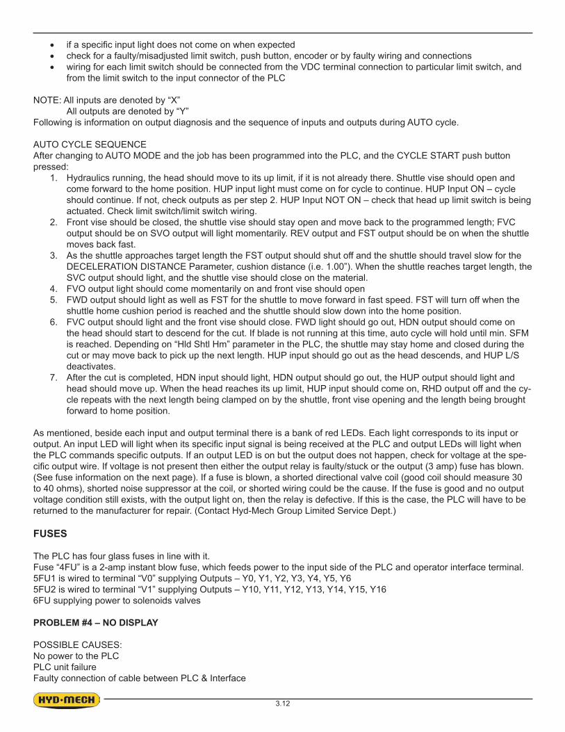
3.12
check for a faulty/misadjusted limit switch, push button, encoder or by faulty wiring and connectionswiring for each limit switch should be connected from the VDC terminal connection to particular limit switch, and from the limit switch to the input connector of the PLC
NOTE: All inputs are denoted by “X”All outputs are denoted by “Y”
Following is information on output diagnosis and the sequence of inputs and outputs during AUTO cycle.
AUTO CYCLE SEQUENCEAfter changing to AUTO MODE and the job has been programmed into the PLC, and the CYCLE START push button pressed:
1. Hydraulics running, the head should move to its up limit, if it is not already there. Shuttle vise should open and come forward to the home position. HUP input light must come on for cycle to continue. HUP Input ON – cycle should continue. If not, check outputs as per step 2. HUP Input NOT ON – check that head up limit switch is being actuated. Check limit switch/limit switch wiring.
2. Front vise should be closed, the shuttle vise should stay open and move back to the programmed length; FVC output should be on SVO output will light momentarily. REV output and FST output should be on when the shuttle moves back fast.
3. As the shuttle approaches target length the FST output should shut off and the shuttle should travel slow for the DECELERATION DISTANCE Parameter, cushion distance (i.e. 1.00”). When the shuttle reaches target length, the SVC output should light, and the shuttle vise should close on the material.
4. FVO output light should come momentarily on and front vise should open5. FWD output should light as well as FST for the shuttle to move forward in fast speed. FST will turn off when the
shuttle home cushion period is reached and the shuttle should slow down into the home position.6. FVC output should light and the front vise should close. FWD light should go out, HDN output should come on
the head should start to descend for the cut. If blade is not running at this time, auto cycle will hold until min. SFM is reached. Depending on “Hld Shtl Hm” parameter in the PLC, the shuttle may stay home and closed during the cut or may move back to pick up the next length. HUP input should go out as the head descends, and HUP L/S deactivates.
7. After the cut is completed, HDN input should light, HDN output should go out, the HUP output should light and head should move up. When the head reaches its up limit, HUP input should come on, RHD output off and the cy-cle repeats with the next length being clamped on by the shuttle, front vise opening and the length being brought forward to home position.
As mentioned, beside each input and output terminal there is a bank of red LEDs. Each light corresponds to its input or
-
(See fuse information on the next page). If a fuse is blown, a shorted directional valve coil (good coil should measure 30 to 40 ohms), shorted noise suppressor at the coil, or shorted wiring could be the cause. If the fuse is good and no output voltage condition still exists, with the output light on, then the relay is defective. If this is the case, the PLC will have to be returned to the manufacturer for repair. (Contact Hyd-Mech Group Limited Service Dept.)
FUSES
The PLC has four glass fuses in line with it.Fuse “4FU” is a 2-amp instant blow fuse, which feeds power to the input side of the PLC and operator interface terminal.5FU1 is wired to terminal “V0” supplying Outputs – Y0, Y1, Y2, Y3, Y4, Y5, Y65FU2 is wired to terminal “V1” supplying Outputs – Y10, Y11, Y12, Y13, Y14, Y15, Y166FU supplying power to solenoids valves
PROBLEM #4 – NO DISPLAY
POSSIBLE CAUSES:No power to the PLCPLC unit failureFaulty connection of cable between PLC & Interface

3.13
DIAGNOSIS:Check POWER LED (see next page – Inputs & Outputs) – to be on when the PLC is switched on. If the light is OFF, PLC may have failed. Check for proper connection of cable at PLC & at interface. If light is not on – check the (2 amp) PLC fuse. If the fuse is OK, check power to it.
PROBLEM #5 – NO BLADE SPEED DISPLAY
POSSIBLE CAUSES:1. Fault at proximity sensor
Bad sensor, misadjusted sensor (gap should be approx. 0.015”)Contamination on the end of the sensor
2. Fault at the PLCBad connection of sensor wiringFaulty PLC input
DIAGNOSIS:Check for LED light on the sensor – light on indicates proximity sensor power connections are correct and sensor is ac-tivated. Problem could be with sensor, signal wire to the PLC or with the PLC. With blade running, proximity LED should pulse. Likewise, the PLC input LED (X2) should be pulsing. If both LEDs are pulsing with the blade running, the PLC is the problem. If the sensor LED is pulsing but the input (X2) LED is not; there is a problem between the sensor and the PLC input (X2) terminal. If the LED on the sensor is not on, the problem is with the sensor wiring or the sensor is at fault.
MITSUBISHI 100 INPUTS AND OUTPUTS
INPUT AND OUTPUT TERMINAL IDENTIFICATION
of terminals. Input and output LED numbers correspond to the Input or Output of the same number.i.e. Input LED #0 corresponds to Input X0. Output LED #0 corresponds to Output Y0.PLC STATUS INDICATORS:Power – on when power exists to the PLCRun – on when the PLC is runningBatt V – on when PLC memory backup battery has low voltage condition

3.14
Input/Output Terminal Information
InputsX0 – Shuttle Encoder, Channel A – (Open on “P”) X10 – Open (Shuttle Vise Close on Seq. and “P”)X1 – Shuttle Encoder, Channel B – (Open on “P”) X11 – Open (Shuttle Vise Open on Seq. and “P”)X2 – Blade Speed X12 – Open (Front Vise Close on Seq. and “P”) X3 – Door safety interlock X13 – Open (Front Vise Open on Seq. and “P”)X4 – Open (Blade Stop on Seq. and “P”) X14 – Open (Head Raise on Seq. and “P”)X5 – Head Lower L/S X15 – Open (Head Lower on Seq. and “P”)X6 – Head Raise L/S X16 – Open (Blade Start on Seq. and “P”)X7 – Out of stock L/S – (Open on “P”) X17 – Open (Blade Stop on Seq. and “P”)
OutputsY0 – Hydraulic Motor Contactor Y10 – Front Vise CloseY1 – Blade Motor Contactor Y11 – Front Vise OpenY2 – Mist Option Y12 – Shuttle Vise Close – (Open on “P”)Y3 – Blade start Y13 – Shuttle Vise Open – (Open on “P”)Y4 – Blade speed increase Y14 – Shuttle Rev – (Open on “P”)Y5 – Blade speed decrease Y15 – Shuttle Fwd – (Open on “P”)Y6 – Coolant pump On/Off Y16 – Head RaiseY7 – Shuttle Fast – (Open on “P”) Y17 – Head Lower Relay
CALIBRATION PROCEDUREFor Mitsubishi PLC100 with 2100 Series software
Length calibration may be achieved in two ways: by inputting the ACTUAL LENGTH or LENGTH CONSTANT parameter.1. To determine ACTUAL LENGTH value, use MANUAL MODE to position a piece of material, which is approx. 5”
longer that the shuttle full stroke length (i.e. S20A = 34.00”) and close the front vise. Start the blade and make a trim cut. Raise the head and fully retract the shuttle. Clamp the material and move the shuttle fully forward.Make a cut and measure the part length.
In SERVICE MODE, move the cursor to the ACTUAL LENGTH parameter and enter the length of the cut part plus the actual kerf value. Then exit the parameters by pressing the RETURN key.
NOTE: When entering the ACTUAL LENGTH, always round down.2. To determine LENGTH CONSTANT value, use this formula:
LENGTH CONSTANT = ENCODER PINION CIRCUMFERENCE (TTd) ENCODER RESOLUTION
Example:For a 1” pinion diameter and 2500 PPR encoder:LTH CONST = TTd 2500 PPR = 0.0012567
TO CHECK LENGTH CONTROL CONSISTENCY:a. Perform test cuts of three different lengths (i.e. 1”, 12”, 20”) and measure as accurately as possible with a Vernier
or dial caliperb. If the measurements indicate a linear problem (measured length error increases as the programmed length in-
creases), the ACTUAL LENGTH or LENGTH CONSTANT value will have to be adjusted.
If part length error gets longer as the programmed length increases, ACTUAL LENGTH value should be de-creasedIf part length error gets shorter as the programmed length increases, ACTUAL LENGTH value should be in-creasedMake small adjustments at a time (i.e. .020” - .030”) and recheck with test cuts

3.15
General Rule: If part length error gets longer as programmed length increases:
Existing ACTUAL LENGTH = 33.070” Change ACTUAL LENGTH to 33.070 - .020 = 33.050”
TO ADJUST LENGTH CONSTANT VALUE:Cut length Programmed length X Existing LENGTH CONSTANT = New LENGTH CONSTANTExample:
Cut length of 11.988”, Programmed length of 12”,Existing LENGTH CONSTANT parameter of 0.0012567.11.988 12.000 X 0.0012567 = 0.0012554The new LENGTH CONSTANT value of 0.0012554 should be entered as the LENGTH CONSTANT parameter and test cuts repeated. Adjust the parameter again if necessary.
General Rule: Lowering the LENGTH CONSTANT value = Longer shuttle travel = Longer partsIncreasing the LENGTH CONSTANT value = Shorter shuttle travel = Shorter parts


4.1
SECTION 4 - ELECTRICAL
MAIN PANEL: COMPONENT LAYOUT
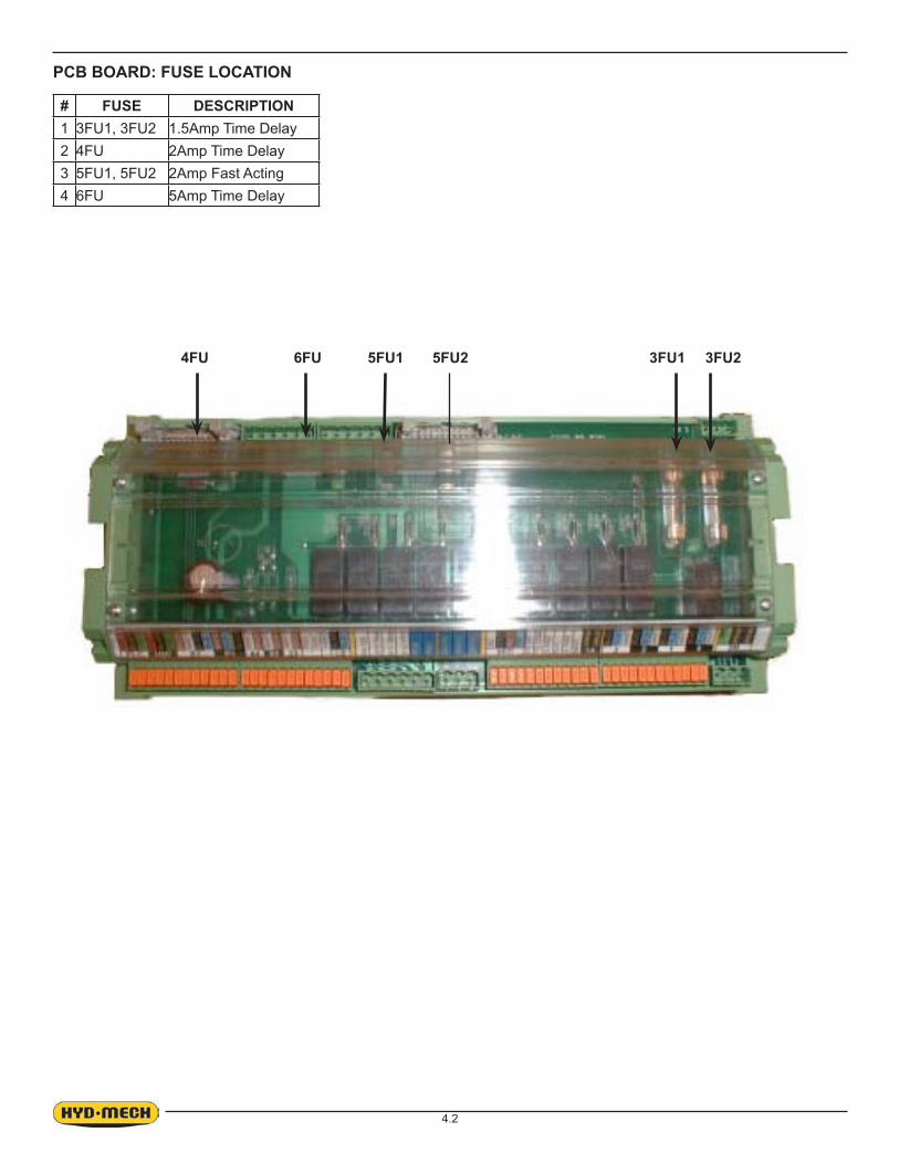
4.2
PCB BOARD: FUSE LOCATION
# FUSE DESCRIPTION1 3FU1, 3FU2 1.5Amp Time Delay2 4FU 2Amp Time Delay3 5FU1, 5FU2 2Amp Fast Acting4 6FU 5Amp Time Delay
5FU2 3FU25FU1 3FU1 6FU4FU

4.3
MAIN PANEL: COMPONENT LAYOUT
PLC OUTPUT CABLECOMMUNICATION CABLE
PLC INPUT CONNECTIONS OUTPUT CONNECTIONSPLC INPUT CABLE
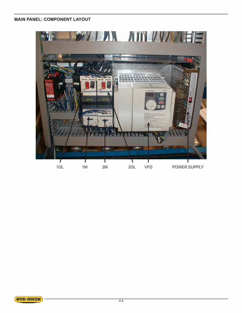
4.4
MAIN PANEL: COMPONENT LAYOUT
1OL 2OL VFD1M 2M POWER SUPPLY

4.5
MAIN PANEL: COMPONENT LAYOUT
# FUSE Description1 2FU1, 2FU2 3Amp Time Delay2 7FU 2Amp Fast Acting
2FU27FU 2FU1SAFETY RELAY

4.6
S20A 3HP OPTION
PART # DESCRIPTION QTY UNIT
342490 Gearmotor, 3 HP, W86, 230/460V, 3 Phase, 60Hz 1.00 EA
S23A 5HP OPTION
PART # DESCRIPTION QTY UNIT
342554 Gearmotor, 5 HP, W110, 230/460V, 3 Phase, 60Hz 1.00 EA
ELECTRICAL SCHEMATIC DRAWING NUMBERS
S22AII - NA - 7 - 00 - 1 Schematic applies to all machines regardless if machine contains PLC or SEQUENCER option.
S22AII - NA - 7 - 01 - 1 Schematic indicates wiring connections required for machine with PLC option.
S22AII - NA - 7 - 02 - 1 Schematic indicates wiring connections required for machine with SEQUENCER option.
S22AII - NA - 7 - 03 - 1 Schematic indicates wiring connections required for Out Of Stock OOS0 option.
S22AII - NA - 7 - 04 - 1 Schematic indicates wiring connections required for Work Lamp option.
S22AII - NA - 7 - 05 - 1 Schematic indicates wiring connections required for Mist Coolant option.
FOR ELECTRICAL SCHEMATICS AND COMPONENTS PARTS LIST SEE PDF ON ATTACHED CD.

5.1
The S20-A, S23-A hydraulic system does not require any special work on a new machine before its start up. The hydrau-
ensure proper operation upon initial start up.
SECTION 5 - HYDRAULIC
ITEM BALLOONNUMBER
QTY PARTNUMBER DESCRIPTION
1 1800006-S23A 800003-S22A Head Cylinder
2 2 800000 Vise Cylinder 3 1 800045 Shuttle Cylinder4 0(2) 800001 Bundling Cylinder (Option)5 1 DDF1-0-00A Ddf Valve6 8b 1 362748 Dcv3P-Ab-T, Head Control Valve7 8a 1 362748 Dcv3P-Ab-T, Shuttle Control Valve8 9a, 9b 2 362749 Dcv3P-Ab-C , Vise Valve 9 7a, 7b 2 362747 Dpch-1, Double Pilot Check Valve
10 10 1 362757 Pv2P-A-C , Chb-20 , Cushion Valve Assembly11 2 1 362752 Pump12 3 1 362753 Motor 240 Vac, 1Hp, Three Phase13 1 362756 Filter Element14 0(1) 362758 Variable Vise Pressure Block (Vvp Option)15 0(1) 363145 Pressure Reducing Valve (Vvp Option)16 5 0(1) 360745 Pressure Gauge (Vvp Option)17 1.4 1 362758 Oil Side Gauge18 0(2) 363205 Ball Valve (Bundling Option)19 0(4) 363220 Flow Control Valve (Bundling Option)20 11 1 362751 Valve, Pressure Reducing Ng 6, Pilot Operated
Hydraulic Power Pack
HYDRAULIC COMPONENT LIST

5.2
Oil level should be maintained at the top portion of the level gauge glass window.
OIL LEVEL GAUGE AND DRAIN PLUG
FILLER CAP AND FILTER ELEMENT LOCATION

5.3
FOR HYDRAULIC SCHEMATICS AND PLUMBING DIAGRAMS SEE PDF ON ATTACHED CD.


6.1
SECTION 6 - MECHANICAL ASSEMBLIES
For Mechanical Assembly Drawings see PDF on attached CD


7.1
OUT OF STOCK SWITCH
length of material is available for the next length advance. Also stops the automatic cycle after completing the last cut.
MIST COOLANT SYSTEM
Mist Coolant – the air powered pump delivers a regulated number of pulses of lubri-cant to a single applicator nozzle.The unit has two control screws.Pulse / Minute – adjusts rate of lubricant use. About 8 to 12 pulse per minute is optimum – more is not better.Air Screw – regulates the jet of air that projects the lubricant from the nozzle onto the blade. Adjustment should be such that lubricant covers the blade without blow-ing the mist beyond the back edge of the blade.
Note: New blade may require initial lubrication with a small quantity of mist coolant applied to the blade at the idler guide arm to prevent squealing.
PULSE / MINUTE AIR SCREW
SECTION 7 - OPTIONAL EQUIPMENT

7.2
VARIABLE VISE PRESSURE OPTION
Vise clamping pressure adjustment is located on the face of hydraulic power pack door. Clamping pressure is indicated by the pressure gauge adjacent to pres-sure control knob. Turning knob clockwise increases clamping pressure. The clamping pressure can be
pressure). It has to be taken under consideration that clamp pressure setting will affect the clamp speed. The actual usable low clamp pressure setting maybe higher than achievable by controls and is limited by mechanical friction of the vise assemblies.
OVERHEAD BUNDLING1. The relative speed of the bundling jaws and vise jaws can be adjusted with the needle valves at each cylinder.
a) The material should be loaded into the machines vises and advanced to a position where a trim can be per-formed.
b) Close the Fixed Vise until the Overhead Bundling Arm is slightly (1/32” to 1/64”) above the material to be cut.c) Close the ball valve
located on the Fixed Overhead Bundling cylinder to lock the position of the Over-head Bundling Arm and then operate as normal.
GAUGE
CONTROL KNOB

7.3
Lamp 24VDC 20W #371789
Work Stop Assembly S22A-G15-00A
WORK LAMP ASSEMBLY
WORK STOP ASSEMBLY
FOR OPTIONAL ASSEMBLIES SEE PDF ON ATTACHED CD


8.1
CAPACITY: 90° Rectangle: 13” x 18” 90° Rectangle: : 330 mm x 457 mm
90° Round: 13” diameter 90° Round: 330 mm
45° Rectangle: 13” x 10.75” 45° Rectangle: 330 mm x 273 mm
45° Round: 12” diameter 45° Round: 305 mm diameter
BLADE: Length: 4115 mmWidth: 1” Width: 25 mm
Thickness: .035” Thickness: 0.8 mmBLADE SPEED: 75-350 SFM 22-107 m/min
(VFD) (VFD)BLADE GUIDES: Carbide CarbideBLADE WHEEL DIAMETER: 16” 406 mmDRIVE: Blade drive: 3 hp (5 hp optional) Blade drive: 2.2 kW (3.7 kW optional)
Hydraulic drive: 1 hp Hydraulic drive: .75 kWHYDRAULIC SYSTEM: 600 psi 4140 kPaHYDRAULIC TANK CAPACITY: 4.75 U.S. Gallons 18 litresCOOLANT TANK: 6 U.S. Gallons 23 litresSHUTTLE STROKE: 0-29” single stroke 0-736 mm single stroke
multi-indexing standard multi-indexing standardVISE CONTROL: Hydraulic HydraulicTABLE HEIGHT: 31” 787 mmMAXIMUM WORK LOAD: 5,000 lbs 2268 kgMACHINE WEIGHT: 3,000 lbs 1360 kgDIMENSIONS: 88” wide 2234 mm wide
80” long 2031 mm long54” high 1370 mm high
OPTIONS: • Full capacity bundling • Full capacity bundling
• Worklight • Worklight
• Variable vise pressure • Variable vise pressure
• Mitsubishi PLC 100 • Mitsubishi PLC 100
• Out of stock switch • Out of stock switch• Outfeed stop • Outfeed stop
SECTION 8 - SPECIFICATIONS

8.2

8.3

8.4

8.5
CAPACITY: 90° Rectangle: 16” x 18” 90° Rectangle: 406 mm x 457 mm90° Round: 16” diameter 90° Round: 406 mm diameter
45° Rectangle: 16” x 10” 45° Rectangle: 406 mm x 254 mm45° Round: 12” diameter 45° Round: 305 mm diameter
BLADE: Length: 4724 mmWidth: 1 1/4” Width: 32 mmThickness: .042” Thickness: 1 mm
BLADE SPEED: 75-350 SFM 22-107 m/min(VFD) (VFD)
BLADE GUIDES: Carbide CarbideBLADE WHEEL DIAMETER: 19” 483 mmDRIVE: Blade drive: 5 hp Blade drive: 3.7 kW
Hydraulic drive: 1 hp Hydraulic drive: .75 kWHYDRAULIC SYSTEM: 600 psi 4140 kPaHYDRAULIC TANK CAPACITY: 4.75 U.S. Gallons 18 litresCOOLANT TANK: 6 U.S. Gallons 23 litresSHUTTLE STROKE: 0-29” single stroke 0-736 mm single stroke
multi-indexing standard multi-indexing standardVISE CONTROL: Hydraulic HydraulicTABLE HEIGHT: 31” 787 mmMAXIMUM WORK LOAD: 5,000 lbs 2268 kgMACHINE WEIGHT: 3,400 lbs 1543 kgDIMENSIONS: 97” wide 2462 mm wide
80” long 2031mm long
60” high 1520 mm highOPTIONS: • Full capacity bundling • Full capacity bundling
• Worklight • Worklight• Variable vise pressure • Variable vise pressure
• Mitsubishi PLC 100 • Mitsubishi PLC 100
• Out of stock switch • Out of stock switch
• Outfeed stop • Outfeed stop

8.6

8.7

8.8

9.1
SECTION 9 - WARRANTY
Warranty
Hyd-Mech Group Ltd. warrants parts/components on each new S-20/23A Series ll bandsaw to be free from failure result-ing from defective material and workmanship under proper use and service for a period of two years following the date
shall disclose to be defective. Return freight must be prepaid by the user.
This warranty, in its entirety, does not cover maintenance items, including but not limited to lubricating grease and oils, -
equate maintenance, or unauthorized altering.
MOTOR, GEARBOX, PUMP, ELECTRIC COMPONENTS, VALVES, HOSES, FITTINGS, and any other items used in the manufacture of the S-20/23A Series ll, but not originally manufactured by Hyd-Mech are subject to the original manu-
Liability or obligation on the part of Hyd-Mech for damages, whether general, special or for negligence and expressly
be the limit of its liability under this warranty and the sole and exclusive right and remedy of the user.
THIS WARRANTY IS EXPRESSLY IN LIEU OF ALL OTHER WARRANTIES, EXPRESSED OR IMPLIED, WRITTEN OR ORAL, INCLUDING WITHOUT LIMITATION ANY IMPLIED WARRANTIES OF MERCHANTABILITY OR FITNESS FOR A PARTICULAR PURPOSE.
Hyd-Mech Group Ltd.1079 Parkinson RoadP.O. Box 1030Woodstock, OntarioN4S 8A4
Phone: (519) 539-6341Fax: (519) 539-5126Toll Free (877)237-0914e-mail, [email protected]

9.2
S22A and S23A PLC and SEQUENCER PARAMETERSDate:Serial #:Voltage:Interface Type:2100 series software Version:
SPEED CONSTANT FEED RATE (Plc Only)No
ACTUAL LENGTH ACTUAL POSITION DISPLAY29.125” NoLENGTH CONSTANT HOLD SHUTTLE HOME
NoACCELERATION DISTANCE BROKEN PROX0.25” NoDECELERATION DISTANCE POWER DOWN TIMER0.75” 15MinMINIMUM FAST DISTANCE BLADE CLEAR 1” NoTARGET WINDOW TRIM CUT0004 YesFRONT VISE OPEN DWELL OUT OF STOCK
NoSHUTTLE VISE OPEN DWELL COOLANT
BLDCLOSE TIME QUEUE (Plc Only)
SingleSEQUENCER (Seq Only) MEASURE UNITS (Seq Only)yes Inch