3a -3.1 to 3.4
DESCRIPTION
TCM_CAP1 E 3 CONDUCAOTRANSCRIPT

One-Dimensional, Steady-StateOne-Dimensional, Steady-StateConduction withoutConduction without
Thermal Energy GenerationThermal Energy Generation
Chapter ThreeChapter Three
Sections 3.1 through 3.4Sections 3.1 through 3.4

Methodology
• Specify appropriate form of the heat equation.
• Solve for the temperature distribution.
• Apply Fourier’s law to determine the heat flux.
Simplest Case: One-Dimensional, Steady-State Conduction with No Thermal Energy
Generation.
• Common Geometries:
– The Plane Wall: Described in rectangular (x) coordinate. Area
perpendicular to direction of heat transfer is constant (independent of x).
– The Tube Wall: Radial conduction through tube wall.
– The Spherical Shell: Radial conduction through shell wall.
Methodology of a Conduction Analysis
Plane Wall
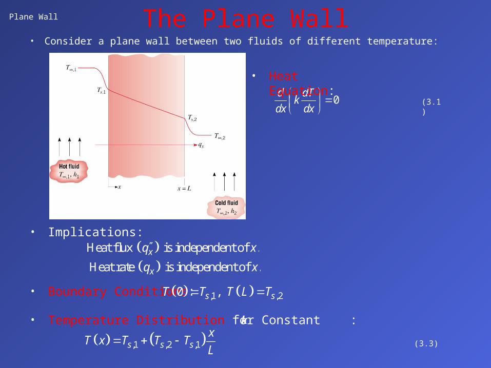
• Consider a plane wall between two fluids of different temperature:
The Plane Wall
• Implications:
0d dT
kdx dx
(3.1)
• Heat Equation:
Heat flux is independent of .xq x
Heat rate is independent of .xq x
• Boundary Conditions: ,1 ,20 , s sT T T L T
• Temperature Distribution for Constant :
,1 ,2 ,1s s sx
T x T T TL
(3.3)
k
Plane Wall (cont.)
• Heat Flux and Heat Rate:
,1 ,2x s sdT k
q k T Tdx L
(3.5)
,1 ,2x s sdT kA
q kA T Tdx L
(3.4)
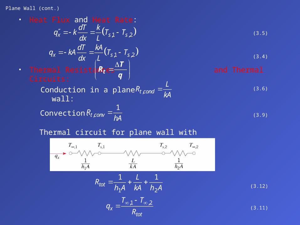
• Thermal Resistances and Thermal Circuits:tT
Rq
Conduction in a plane wall: ,t condL
RkA
(3.6)
Convection: ,1
t convRhA
(3.9)
Thermal circuit for plane wall with adjoining fluids:
1 2
1 1tot
LR
h A kA h A
(3.12)
,1 ,2x
tot
T Tq
R
(3.11)
Plane Wall (cont.)
• Thermal Resistance for Unit Surface Area:
,t condL
Rk
,1
t convRh
Units: K/WtR 2m K/WtR
• Radiation Resistance:
,1
t radr
Rh A
,1
t radr
Rh
2 2r s sur s surh T T T T (1.9)
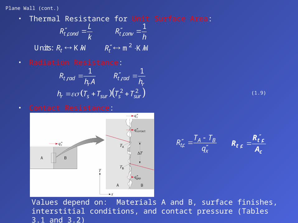
• Contact Resistance:
,A B
tcx
T TR
q
t c
t cc
RR
A,
,
Values depend on: Materials A and B, surface finishes, interstitial conditions, and contact pressure (Tables 3.1 and 3.2)
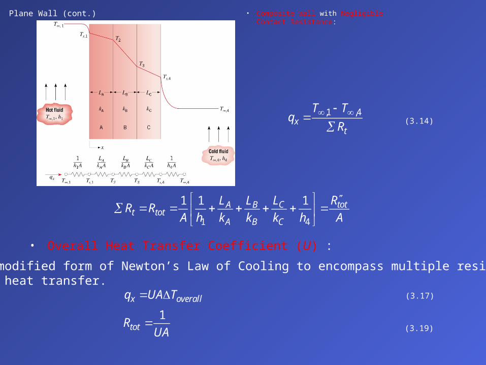
Plane Wall (cont.) • Composite Wall with Negligible Contact Resistance:
,1 ,4x
t
T Tq
R
(3.14)
1 4
1 1 1C totA Bt tot
A B C
L RL LR R
A h k k k h A
• Overall Heat Transfer Coefficient (U) :
A modified form of Newton’s Law of Cooling to encompass multiple resistances to heat transfer.
x overallq UA T (3.17)
1totR
UA (3.19)

• Series – Parallel Composite Wall:
Plane Wall (cont.)
• Note departure from one-dimensional conditions for .F Gk k
• Circuits based on assumption of isothermal surfaces normal to x direction or adiabatic surfaces parallel to x direction provide approximations for .xq
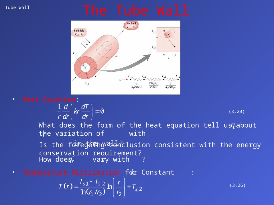
Tube Wall
• Heat Equation:
The Tube Wall
10
d dTkr
r dr dr
(3.23)
Is the foregoing conclusion consistent with the energy conservation requirement?
How does vary with ?rq r
What does the form of the heat equation tell us about the variation of with
in the wall? rq
r
• Temperature Distribution for Constant :k
,1 ,2
,21 2 2
lnln /
s ss
T T rT r T
r r r
(3.26)

Tube Wall (Cont.)
• Heat Flux and Heat Rate:
,1 ,22 1
,1 ,22 1
,1 ,22 1
ln /
22
ln /
22
ln /
r s s
r r s s
r r s s
dT kq k T T
dr r r r
kq rq T T
r r
Lkq rLq T T
r r
(3.27)
• Conduction Resistance:
2 1,
2 1,
ln /Units K/W
2ln /
Units m K/W2
t cond
t cond
r rR
Lkr r
Rk
(3.28)
Why is it inappropriate to base the thermal resistance on a unit surface area?

Tube Wall (Cont.)
• Composite Wall with Negligible Contact
Resistance
,1 ,4,1 ,4r
tot
T Tq UA T T
R
(3.30)
1
Note that
is a constant independent of radius.totUA R
But, U itself is tied to specification of an interface.
1i i totU A R
(3.32)
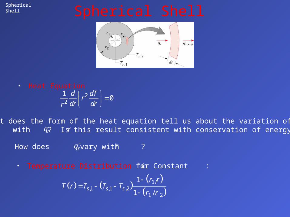
Spherical Shell
• Heat Equation
Spherical Shell
22
10
d dTr
dr drr
What does the form of the heat equation tell us about the variation of with ? Is this result consistent with conservation of energy?rq r
How does vary with ? rq r
• Temperature Distribution for Constant :k
1/,1 ,1 ,2
1 2
1
1 /s s s
r rT r T T T
r r
Spherical Shell (cont.)
• Heat flux, Heat Rate and Thermal Resistance:
,1 ,22
1 21/ 1/r s s
dT kq k T T
dr r r r
(3.35) 2,1 ,2
1 2
44
1/ 1/r r s sk
q r q T Tr r
• Composite Shell:
overallr overall
tot
Tq UA T
R
1 ConstanttotUA R
1 Depends on i i tot iU A R A
1 2,
1/ 1/
4t condr r
Rk
(3.36)

Problem: Thermal Barrier Coating
Problem 3.23: Assessment of thermal barrier coating (TBC) for protectionof turbine blades. Determine maximum blade temperaturewith and without TBC.
Schematic:
ASSUMPTIONS: (1) One-dimensional, steady-state conduction in a composite plane wall, (2) Constant properties, (3) Negligible radiation
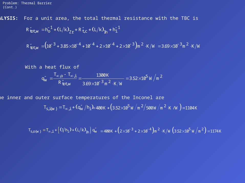
Problem: Thermal Barrier (Cont.)
3 4 4 4 3 2 3 2tot,wR 10 3.85 10 10 2 10 2 10 m K W 3.69 10 m K W
3 4 2 5 2400 K 2 10 2 10 m K W 3.52 10 W m 1174 K s,o(w) ,i i wInT T 1 h L k q
,o ,i 5 2w 3 2tot,w
T T 1300 Kq 3.52 10 W m
R 3.69 10 m K W
With a heat flux of
the inner and outer surface temperatures of the Inconel are
s,i(w) ,i w iT T q h 5 2 2400 K 3.52 10 W m 500 W m K / W 1104 K
ANALYSIS: For a unit area, the total thermal resistance with the TBC is
1 1tot,w o t,c iZr InR h L k R L k h

Problem: Thermal Barrier (Cont.) 3
Without the TBC,
1 1 3 23 20 10 m K W
tot ,wo o iInR h L k h .
The inner and outer surface temperatures of the Inconel are then
1212 Ks,i( wo ) ,i wo iT T q h
1 1293 Ks ,o( wo ) ,i i woInT T h L k q
Use of the TBC facilitates operation of the Inconel below Tmax = 1250 K.
COMMENTS: Since the durability of the TBC decreases with increasing temperature, which increases with increasing thickness, limits to its thickness are associated with reliability considerations.
wo ,o ,i tot ,woq T T R 4.06105 W/m2
Problem: Radioactive Waste Decay
SCHEMATIC:
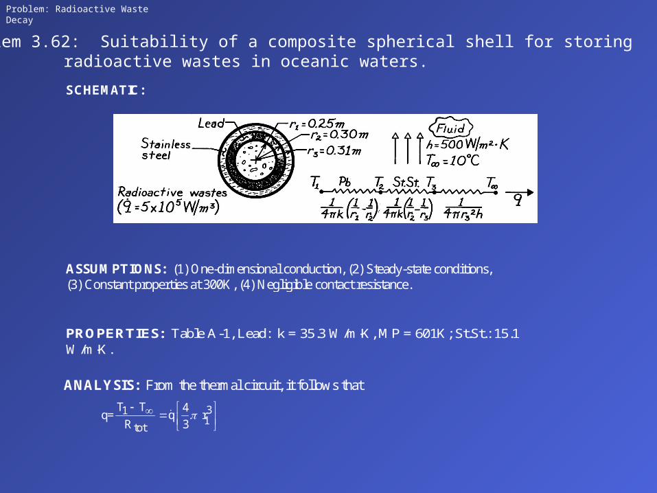
Problem 3.62: Suitability of a composite spherical shell for storingradioactive wastes in oceanic waters.
ASSUMPTIONS: (1) One-dimensional conduction, (2) Steady-state conditions, (3) Constant properties at 300K, (4) Negligible contact resistance.
PROPERTIES: Table A-1, Lead: k = 35.3 W/mK, MP = 601K; St.St.: 15.1 W/mK.
ANALYSIS: From the thermal circuit, it follows that
311
tot
T T 4q= q r
R 3
Problem: Radioactive Waste Decay
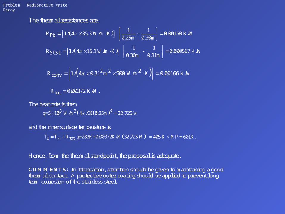
The thermal resistances are:
Pb1 1
R 1/ 4 35.3 W/m K 0.00150 K/W0.25m 0.30m
St.St.1 1
R 1/ 4 15.1 W/m K 0.000567 K/W0.30m 0.31m
2 2 2convR 1/ 4 0.31 m 500 W/m K 0.00166 K/W
totR 0.00372 K/W.
The heat rate is then
35 3q=5 10 W/m 4 / 3 0.25m 32,725 W
and the inner surface temperature is 1 totT T R q=283K+0.00372K/W 32,725 W 405 K < MP = 601K.
Hence, from the thermal standpoint, the proposal is adequate.
COMMENTS: In fabrication, attention should be given to maintaining a good thermal contact. A protective outer coating should be applied to prevent long term corrosion of the stainless steel.