3ah47 vacuum circuit-breakers for traction applications
TRANSCRIPT
3AH47 Vacuum Circuit-Breakers
for Traction Applications
Medium-Voltage EquipmentSelection and Ordering Data
Catalog HG 11.52 · 2010
Answers for energy.
2 Siemens HG 11.52 · 2010
3AH47 Vacuum Circuit-Breakers
R-HG
11-1
72.ti
f
2
1
3
4
3Siemens HG 11.52 · 2010
3AH47 Vacuum Circuit-Breakers
3AH47 VacuumCircuit-Breakers
Medium-Voltage EquipmentCatalog HG 11.52 · 2010
Invalid:Catalog HG 11.52 · 2007Catalog HG 11.52 · 2008 (PDF version only)
Contents Page
DescriptionGeneral
Construction and mode of operation, standards
Ambient conditions, current carrying capacityand dielectric strength
Product range overview and basic equipment
56
7
9
10
Equipment SelectionOrdering data and configuration example
Selection of basic types, circuit-breakers(single-pole or two-pole)
Selection of secondary equipment
Selection of additional equipment
Accessories and spare parts
1112
13
14
22
23
Technical DataElectrical data, dimensions and weights
Circuit diagrams
Operating times, short-circuit protection ofmotors, consumption data of releases
2526
30
32
AnnexInquiry form
Configuration instructions
Configuration aid
3334
35
Contents
Foldout page
4 Siemens HG 11.52 · 2010
R-HG
11-2
14.ti
f
3AH47 Vacuum Circuit-Breakers
1
Siemens HG 11.52 · 2010 5
3AH47 Vacuum Circuit-Breakers DescriptionContents
Contents Page
Description
General
Construction and mode of operation:
Switching medium
Pole assembly
Operating mechanism box
Operating mechanism
Trip-free mechanism
Releases
Closing
Circuit-breaker tripping signal
Interlocking
Standards
Ambient conditions
Current carrying capacity
Dielectric strength
Product range overview
Basic equipment
5
6
7
7
7
7
7
8
8
8
8
8
9
9
9
10
10
Railway control center
R-HG
11-2
15.ti
f
1
Siemens HG 11.52 · 20106
3AH47 Vacuum Circuit-Breakers
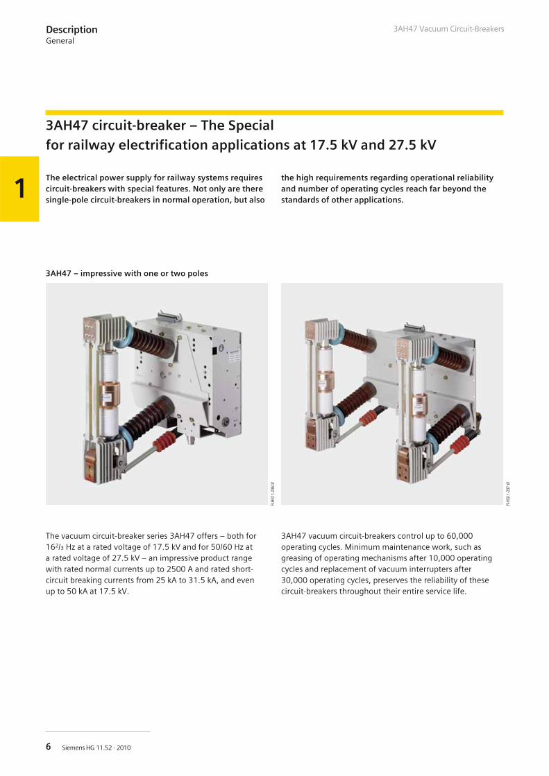
3AH47 – impressive with one or two poles
3AH47 circuit-breaker – The Specialfor railway electrification applications at 17.5 kV and 27.5 kV
DescriptionGeneral
R-HG
11-2
06.ti
f
R-HG
11-2
07.ti
f
The electrical power supply for railway systems requirescircuit-breakers with special features. Not only are theresingle-pole circuit-breakers in normal operation, but also
the high requirements regarding operational reliabilityand number of operating cycles reach far beyond thestandards of other applications.
The vacuum circuit-breaker series 3AH47 offers – both for162/3 Hz at a rated voltage of 17.5 kV and for 50/60 Hz ata rated voltage of 27.5 kV – an impressive product rangewith rated normal currents up to 2500 A and rated short-circuit breaking currents from 25 kA to 31.5 kA, and evenup to 50 kA at 17.5 kV.
3AH47 vacuum circuit-breakers control up to 60,000operating cycles. Minimum maintenance work, such asgreasing of operating mechanisms after 10,000 operatingcycles and replacement of vacuum interrupters after30,000 operating cycles, preserves the reliability of thesecircuit-breakers throughout their entire service life.
1
Siemens HG 11.52 · 2010 7
3AH47 Vacuum Circuit-Breakers
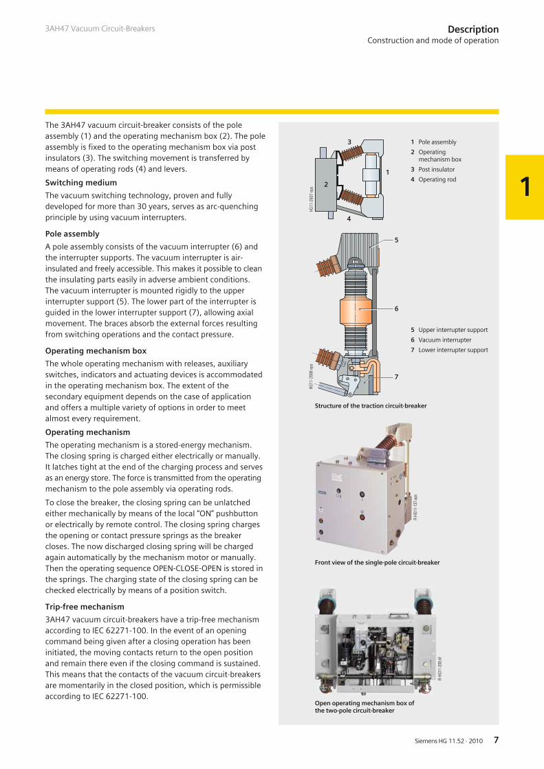
The 3AH47 vacuum circuit-breaker consists of the poleassembly (1) and the operating mechanism box (2). The poleassembly is fixed to the operating mechanism box via postinsulators (3). The switching movement is transferred bymeans of operating rods (4) and levers.
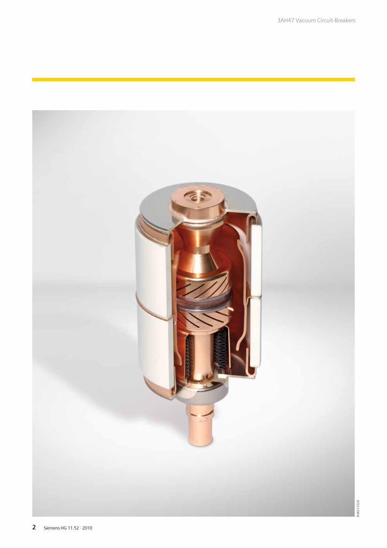
Switching medium
The vacuum switching technology, proven and fullydeveloped for more than 30 years, serves as arc-quenchingprinciple by using vacuum interrupters.
Pole assembly
A pole assembly consists of the vacuum interrupter (6) andthe interrupter supports. The vacuum interrupter is air-insulated and freely accessible. This makes it possible to cleanthe insulating parts easily in adverse ambient conditions.The vacuum interrupter is mounted rigidly to the upperinterrupter support (5). The lower part of the interrupter isguided in the lower interrupter support (7), allowing axialmovement. The braces absorb the external forces resultingfrom switching operations and the contact pressure.
Operating mechanism box
The whole operating mechanism with releases, auxiliaryswitches, indicators and actuating devices is accommodatedin the operating mechanism box. The extent of thesecondary equipment depends on the case of applicationand offers a multiple variety of options in order to meetalmost every requirement.
Operating mechanism
The operating mechanism is a stored-energy mechanism.The closing spring is charged either electrically or manually.It latches tight at the end of the charging process and servesas an energy store. The force is transmitted from the operatingmechanism to the pole assembly via operating rods.
To close the breaker, the closing spring can be unlatchedeither mechanically by means of the local “ON” pushbuttonor electrically by remote control. The closing spring chargesthe opening or contact pressure springs as the breakercloses. The now discharged closing spring will be chargedagain automatically by the mechanism motor or manually.Then the operating sequence OPEN-CLOSE-OPEN is stored inthe springs. The charging state of the closing spring can bechecked electrically by means of a position switch.
Trip-free mechanism
3AH47 vacuum circuit-breakers have a trip-free mechanismaccording to IEC 62271-100. In the event of an openingcommand being given after a closing operation has beeninitiated, the moving contacts return to the open positionand remain there even if the closing command is sustained.This means that the contacts of the vacuum circuit-breakersare momentarily in the closed position, which is permissibleaccording to IEC 62271-100.
����
����
��
�
�
�
�
����
����
���
�
�
�
DescriptionConstruction and mode of operation
R-HG
11-1
37.e
ps
1 Pole assembly
2 Operatingmechanism box
3 Post insulator
4 Operating rod
5 Upper interrupter support
6 Vacuum interrupter
7 Lower interrupter support
Structure of the traction circuit-breaker
Front view of the single-pole circuit-breaker
Open operating mechanism box ofthe two-pole circuit-breaker
R-HG
11-2
08.ti
f
1
Siemens HG 11.52 · 20108
3AH47 Vacuum Circuit-Breakers
Releases
A release is a device which transfers electrical commandsfrom an external source, such as a control room, to thelatching mechanism of the vacuum circuit-breaker so that itcan be opened or closed. How many releases are used andhow they are combined is defined when the secondaryequipment is selected.
• The closing solenoid unlatches the charged closing springof the vacuum circuit-breaker, closing it by electrical means.
• Shunt releases are used for tripping the circuit-breakersvia protection relay and for manual tripping via electricaloperation. For this purpose they are operated with anauxiliary voltage (AC or DC) supplied by the protection relayor the control room.
• Instantaneous releases are used for switching duties withextremely short breaking times, especially for applications in162/3 Hz systems, in order to keep the arcing time short. Foroperation of the instantaneous release, a capacitor trippingunit is required additionally.
• Undervoltage releases comprise a stored-energy mechanism,an unlatching mechanism and an electromagnetic system,which is permanently connected to voltage while thevacuum circuit-breaker is closed.
If the voltage falls below a predetermined value, unlatchingof the release is enabled and the circuit-breaker is openedvia the stored-energy mechanism.
Closing
In the standard version, the 3AH47 vacuum circuit-breakerscan be remote-closed electrically. They can also be closedlocally by mechanical unlatching of the closing spring viapushbutton.
Instead of this “manual mechanical closing”, “manualelectrical closing” is also available. In this version, the closingcircuit of the circuit-breaker is controlled electrically by apushbutton instead of the mechanical button. In this way,switchgear-related interlocks can also be considered for localoperation in order to prevent involuntary closing.
If constant CLOSE and OPEN commands are present at thevacuum circuit-breaker at the same time, the vacuumcircuit-breaker will return to the open position after closing.It remains in this position until a new CLOSE command isgiven. In this manner, continuous closing and opening(=“pumping”) is prevented.
Circuit-breaker tripping signal
The NO contact makes brief contact while the vacuumcircuit-breaker is opening, and this is often used to operatea hazard-warning system which, however, is only allowedto respond to automatic tripping of the vacuum circuit-breaker. Therefore, the signal from the NO contact mustbe interrupted when the circuit-breaker is being openedintentionally. This is accomplished under local control withthe cut-out switch that is connected in series with the NOcontact.
Interlocking
Mechanical interlocking
The switch position of the circuit-breaker is checked from theswitchgear side, and its closing is blocked if the associateddisconnector is in faulty position. On the other hand, dis-connector operation is prevented while the circuit-breaker isclosed. Accordingly, the mechanical interlocking can also beused to interlock against circuit-breaker trucks or withdrawableparts.
Electrical interlocking
The vacuum circuit-breakers can be integrated in electro-magnetic feeder or switchgear interlocks. In case of electricalinterlocking, the disconnector or its operating mechanism isequipped with a magnetic lock-out mechanism. Thismechanism is controlled by an auxiliary contact of thecircuit-breaker, so that the disconnector can only beoperated when the circuit-breaker is open. On the otherhand, the circuit-breaker is also controlled by thedisconnector or its operating mechanism, so that it can onlybe closed when the disconnector is in an end position. Forthis purpose, manual electrical closing must be provided inthe circuit-breaker operating mechanism (see “Closing”).
Standards
3AH47 vacuum circuit-breakers conform to the followingstandards:
• EN 50152-1• IEC 62271-100 (former IEC 60056)• IEC 62271-1 (former IEC 60694)• BS 5311• VDE 0671 (former VDE 0670)
All 3AH47 vacuum circuit-breakers fulfill the enduranceclasses E2 and C2 according to IEC 62271-100, and surpassthe endurance class M2 six times (60,000 operating cycles).
DescriptionConstruction and mode of operation, standards
1
Siemens HG 11.52 · 2010 9
3AH47 Vacuum Circuit-Breakers
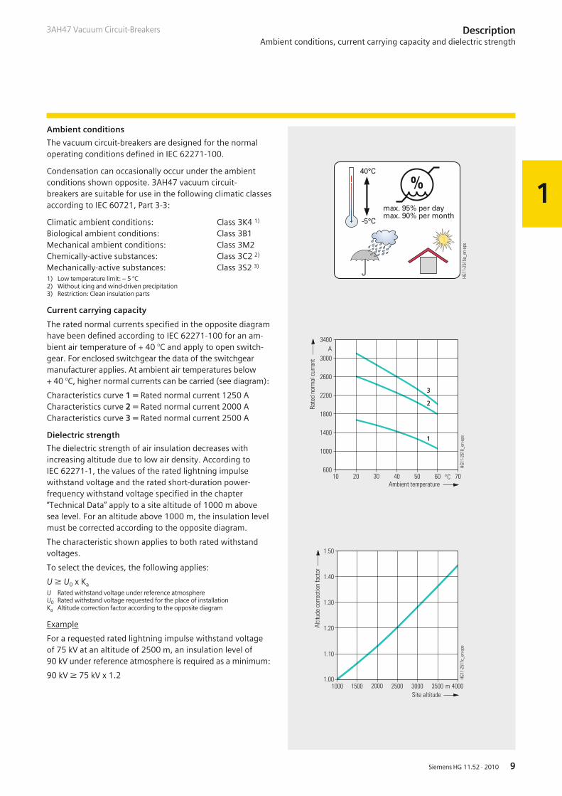
Ambient conditions
The vacuum circuit-breakers are designed for the normaloperating conditions defined in IEC 62271-100.
Condensation can occasionally occur under the ambientconditions shown opposite. 3AH47 vacuum circuit-breakers are suitable for use in the following climatic classesaccording to IEC 60721, Part 3-3:
Climatic ambient conditions: Class 3K4 1)
Biological ambient conditions: Class 3B1Mechanical ambient conditions: Class 3M2Chemically-active substances: Class 3C2 2)
Mechanically-active substances: Class 3S2 3)
1) Low temperature limit: – 5 °C2) Without icing and wind-driven precipitation3) Restriction: Clean insulation parts
Current carrying capacity
The rated normal currents specified in the opposite diagramhave been defined according to IEC 62271-100 for an am-bient air temperature of + 40 °C and apply to open switch-gear. For enclosed switchgear the data of the switchgearmanufacturer applies. At ambient air temperatures below+ 40 °C, higher normal currents can be carried (see diagram):
Characteristics curve 1 = Rated normal current 1250 ACharacteristics curve 2 = Rated normal current 2000 ACharacteristics curve 3 = Rated normal current 2500 A
Dielectric strength
The dielectric strength of air insulation decreases withincreasing altitude due to low air density. According toIEC 62271-1, the values of the rated lightning impulsewithstand voltage and the rated short-duration power-frequency withstand voltage specified in the chapter“Technical Data” apply to a site altitude of 1000 m abovesea level. For an altitude above 1000 m, the insulation levelmust be corrected according to the opposite diagram.
The characteristic shown applies to both rated withstandvoltages.
To select the devices, the following applies:
U W U0 x Ka
U Rated withstand voltage under reference atmosphereU0 Rated withstand voltage requested for the place of installationKa Altitude correction factor according to the opposite diagram
Example
For a requested rated lightning impulse withstand voltageof 75 kV at an altitude of 2500 m, an insulation level of90 kV under reference atmosphere is required as a minimum:
90 kV W 75 kV x 1.2
DescriptionAmbient conditions, current carrying capacity and dielectric strength
����
����
����
��
����������������
����
����
����
����
�������� ���� �����
����
������������
�����
���
�� �
����
�!�
���
����
����
����
�
��������
����
����
����
����
� ��
����
����
����� �� ��"#
�
��$�������� ��� �
%���
���
���
��
���
�
�
�
����
����
��� ������������ ������������
����
����
����
��
1
Siemens HG 11.52 · 201010
3AH47 Vacuum Circuit-Breakers
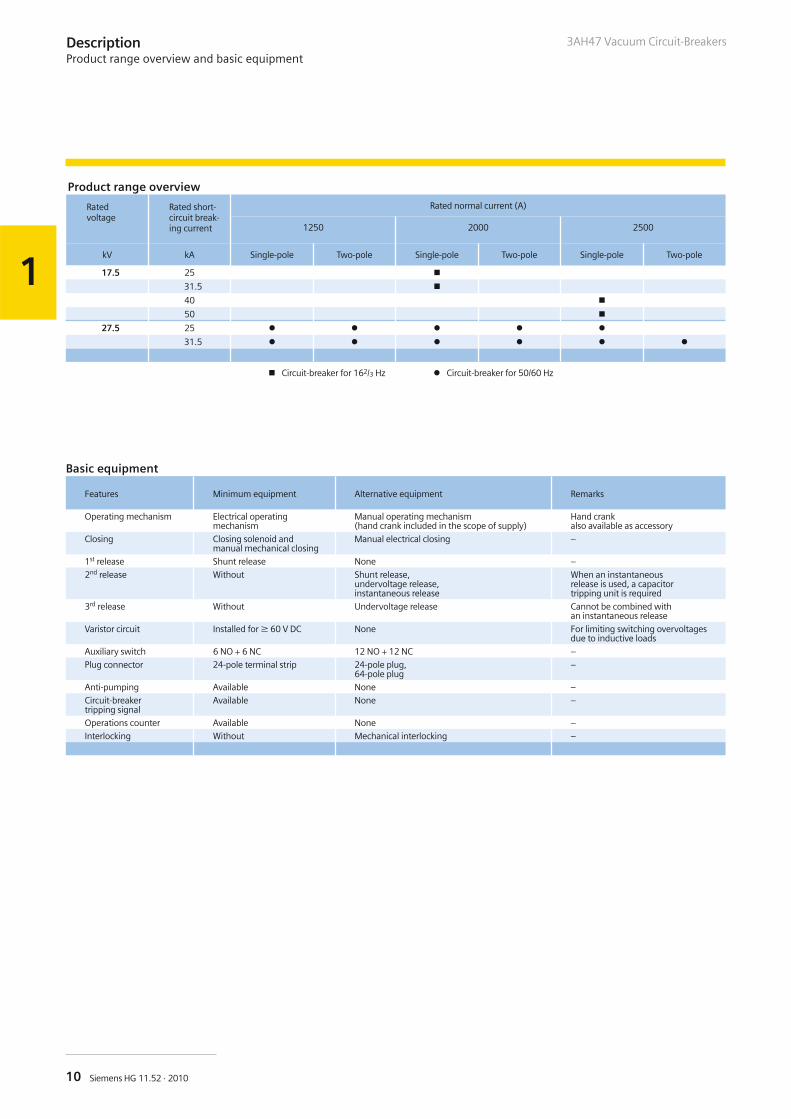
Product range overview
Ratedvoltage
Rated short-circuit break-ing current
Rated normal current (A)
1250 2000 2500
kV kA Single-pole Two-pole Single-pole Two-pole Single-pole Two-pole
17.5 25 �
31.5 �
40 �
50 �
27.5 25 � � � � �
31.5 � � � � � �
� Circuit-breaker for 162/3 Hz � Circuit-breaker for 50/60 Hz
Basic equipment
Features Minimum equipment Alternative equipment Remarks
Operating mechanism Electrical operatingmechanism
Manual operating mechanism(hand crank included in the scope of supply)
Hand crankalso available as accessory
Closing Closing solenoid andmanual mechanical closing
Manual electrical closing –
1st release Shunt release None –
2nd release Without Shunt release,undervoltage release,instantaneous release
When an instantaneousrelease is used, a capacitortripping unit is required
3rd release Without Undervoltage release Cannot be combined withan instantaneous release
Varistor circuit Installed for W 60 V DC None For limiting switching overvoltagesdue to inductive loads
Auxiliary switch 6 NO + 6 NC 12 NO + 12 NC –
Plug connector 24-pole terminal strip 24-pole plug,64-pole plug
–
Anti-pumping Available None –
Circuit-breakertripping signal
Available None –
Operations counter Available None –
Interlocking Without Mechanical interlocking –
DescriptionProduct range overview and basic equipment
2
11Siemens HG 11.52 · 2010
3AH47 Vacuum Circuit-Breakers
Contents Page
Equipment Selection
Ordering data and configuration example
Selection of basic types, circuit-breakers(single-pole or two-pole):
Voltage level 17.5 kV; 162/3 Hz
Voltage level 27.5 kV; 50/60 Hz
Selection of secondary equipment:
Release combination
Operating voltage, closing solenoid
Operating voltage, 1st shunt release
Operating voltage, 2nd release
Operating voltage, 3rd release
Operating voltage of the operating mechanism
Auxiliary switch, secondary connection, interlocking
Languages and frequency
Selection of additional equipment
Accessories and spare parts
11
12
13
13
14
15
16
17
18
19
20
21
22
23
Equipment SelectionContents
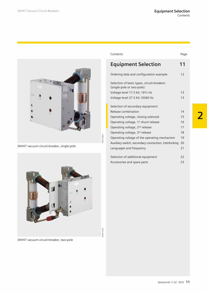
3AH47 vacuum circuit-breaker, two-pole
3AH47 vacuum circuit-breaker, single-pole
R-HG
11-2
09.ti
fR-
HG11
-210
.tif
2
12 Siemens HG 11.52 · 2010
3AH47 Vacuum Circuit-BreakersEquipment SelectionOrdering data and configuration example
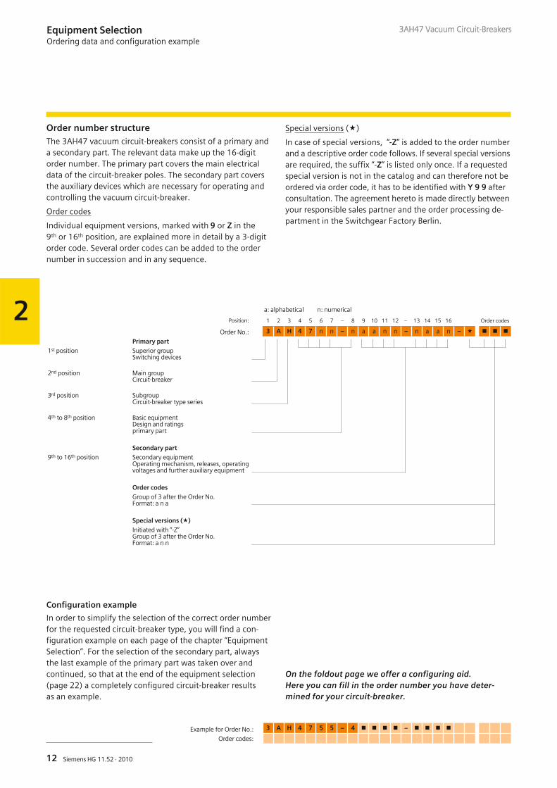
Order number structureThe 3AH47 vacuum circuit-breakers consist of a primary anda secondary part. The relevant data make up the 16-digitorder number. The primary part covers the main electricaldata of the circuit-breaker poles. The secondary part coversthe auxiliary devices which are necessary for operating andcontrolling the vacuum circuit-breaker.
Order codes
Individual equipment versions, marked with 9 or Z in the9th or 16th position, are explained more in detail by a 3-digitorder code. Several order codes can be added to the ordernumber in succession and in any sequence.
Special versions (�)
In case of special versions, “-Z” is added to the order numberand a descriptive order code follows. If several special versionsare required, the suffix “-Z” is listed only once. If a requestedspecial version is not in the catalog and can therefore not beordered via order code, it has to be identified with Y 9 9 afterconsultation. The agreement hereto is made directly betweenyour responsible sales partner and the order processing de-partment in the Switchgear Factory Berlin.
Configuration example
In order to simplify the selection of the correct order numberfor the requested circuit-breaker type, you will find a con-figuration example on each page of the chapter “EquipmentSelection”. For the selection of the secondary part, alwaysthe last example of the primary part was taken over andcontinued, so that at the end of the equipment selection(page 22) a completely configured circuit-breaker resultsas an example.
On the foldout page we offer a configuring aid.Here you can fill in the order number you have deter-mined for your circuit-breaker.
a: alphabetical n: numerical
Position: 1 2 3 4 5 6 7 – 8 9 10 11 12 – 13 14 15 16 Order codes
Order No.: 3 A H 4 7 n n – n a a n n – n a a n – � � � �
Primary part1st position Superior group
Switching devices
2nd position Main groupCircuit-breaker
3rd position SubgroupCircuit-breaker type series
4th to 8th position Basic equipmentDesign and ratingsprimary part
Secondary part9th to 16th position Secondary equipment
Operating mechanism, releases, operatingvoltages and further auxiliary equipment
Order codesGroup of 3 after the Order No.Format: a n a
Special versions (�)Initiated with “-Z”Group of 3 after the Order No.Format: a n n
Example for Order No.: 3 A H 4 7 5 5 – 4 � � � � – � � � �
Order codes:
3AH47 Vacuum Circuit-Breakers
2
13Siemens HG 11.52 · 2010
3AH47 Vacuum Circuit-Breakers
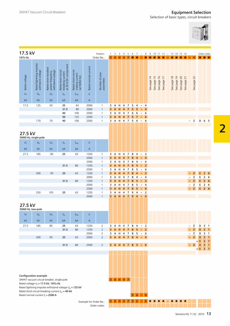
17.5 kV Position: 1 2 3 4 5 6 7 – 8 9 10 11 12 – 13 14 15 16 Order codes
162/3 Hz Order No.: 3 A H 4 7 � � – � � � � � – � � � � – � � � �
Ur Up Ud Isc Ima Ir
kV kV kV kA kA A
17.5 125 50 25 63 2000 1 3 A H 4 7 5 4 – 431.5 80 2000 1 3 A H 4 7 5 5 – 440 100 2500 1 3 A H 4 7 6 6 – 650 125 2500 1 3 A H 4 7 5 7 – 6
170 70 40 100 2500 1 3 A H 4 7 5 6 – 6 – Z D 6 5
27.5 kV50/60 Hz, single-pole
Ur Up Ud Isc Ima Ir
kV kV kV kA kA A
27.5 185 85 25 63 1250 1 3 A H 4 7 8 4 – 22000 1 3 A H 4 7 8 4 – 42500 1 3 A H 4 7 8 4 – 6
31.5 80 1250 1 3 A H 4 7 8 5 – 22500 1 3 A H 4 7 8 5 – 6
200 95 25 63 1250 1 3 A H 4 7 8 4 – 2 – Z E 2 62000 1 3 A H 4 7 8 4 – 4 – Z E 2 6
31.5 80 1250 1 3 A H 4 7 8 5 – 2 – Z E 2 62000 1 3 A H 4 7 8 5 – 4 – Z E 2 62500 1 3 A H 4 7 8 5 – 6 – Z E 2 6
250 105 25 63 1250 1 3 A H 4 7 9 4 – 22000 1 3 A H 4 7 9 4 – 4
27.5 kV50/60 Hz, two-pole
Ur Up Ud Isc Ima Ir
kV kV kV kA kA A
27.5 185 85 25 63 1250 2 3 A H 4 7 8 4 – 2 – Z D 3 131.5 80 1250 2 3 A H 4 7 8 5 – 2 – Z D 3 1
2500 2 3 A H 4 7 8 5 – 6 – Z D 3 1200 95 25 63 2000 2 3 A H 4 7 8 4 – 4 – Z D 3 1
+ E 2 731.5 80 2500 2 3 A H 4 7 8 5 – 6 – Z D 3 1
+ E 2 7
Configuration example
3AH47 vacuum circuit-breaker, single-pole 3 A H 4 7
Rated voltage Ur = 17.5 kV, 162/3 Hz
Rated lightning impulse withstand voltage Up = 125 kV
Rated short-circuit breaking current Isc = 40 kA
Rated normal current Ir = 2500 A 5 6 – 6
See
page
14
See
page
15
See
page
16
See
page
17
See
page
18
See
page
19
See
page
20
See
page
21
See
page
22
Rate
dvo
ltage
Rate
dlig
htni
ngim
puls
ew
ithst
and
volta
ge
Rate
dsh
ort-
dura
tion
pow
er-f
requ
ency
with
stan
dvo
ltage
Rate
dsh
ort-
circ
uit
brea
king
curr
ent
at36
%D
Cco
mpo
nent
Rate
dsh
ort-
circ
uit
mak
ing
curr
ent
(at5
0/60
Hz)
Rate
dno
rmal
curr
ent
Num
bero
fpol
eas
sem
blie
s
Equipment SelectionSelection of basic types, circuit-breakers
3AH47 Vacuum Circuit-Breakers
Example for Order No.: 3 A H 4 7 5 6 – 6 � � � � – � � � �
Order codes:
2
14 Siemens HG 11.52 · 2010
3AH47 Vacuum Circuit-BreakersEquipment SelectionSelection of secondary equipment
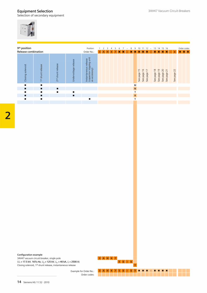
9th position Position: 1 2 3 4 5 6 7 – 8 9 10 11 12 – 13 14 15 16 Order codes
Release combination Order No.: 3 A H 4 7 � � – � � � � � – � � � � – � � � �
� � M� � � N� � � � T� � � R� � � Y
Configuration example
3AH47 vacuum circuit-breaker, single-pole 3 A H 4 7
(Ur = 17.5 kV, 162/3 Hz, Up = 125 kV, Isc = 40 kA, Ir = 2500 A) 5 6 – 6
Closing solenoid, 1st shunt release, instantaneous release Y
See
page
15
See
page
16
See
page
17
See
page
18
See
page
19
See
page
20
See
page
21
See
page
22
Clo
sin
gso
len
oid
1st
shu
nt
rele
ase
2n
dsh
un
tre
leas
e
Un
derv
olta
gere
leas
e
Inst
anta
neo
us
rele
ase
(cap
acit
ortr
ippi
ng
un
itas
acce
ssor
y)
3AH47 Vacuum Circuit-Breakers
Example for Order No.: 3 A H 4 7 5 6 – 6 Y � � � – � � � �
Order codes:
2
15Siemens HG 11.52 · 2010
3AH47 Vacuum Circuit-Breakers Equipment SelectionSelection of secondary equipment
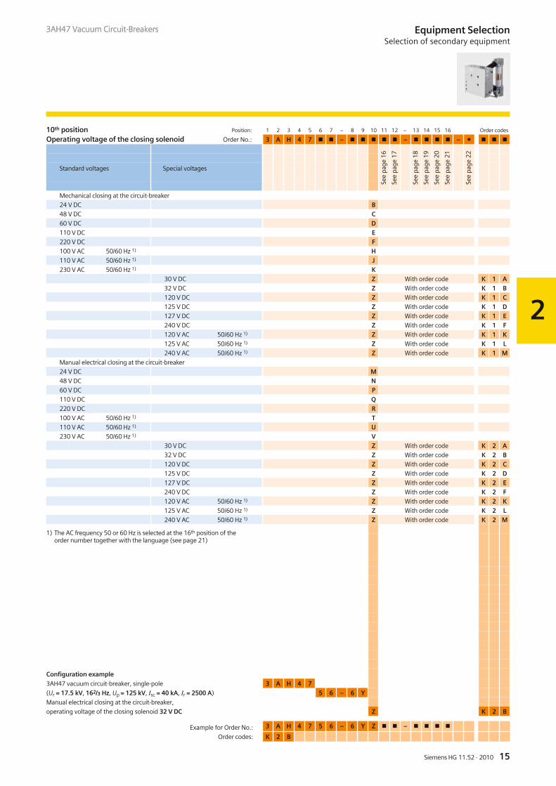
10th position Position: 1 2 3 4 5 6 7 – 8 9 10 11 12 – 13 14 15 16 Order codes
Operating voltage of the closing solenoid Order No.: 3 A H 4 7 � � – � � � � � – � � � � – � � � �
Mechanical closing at the circuit-breaker
24 V DC B48 V DC C60 V DC D110 V DC E220 V DC F100 V AC 50/60 Hz 1) H110 V AC 50/60 Hz 1) J230 V AC 50/60 Hz 1) K
30 V DC Z With order code K 1 A32 V DC Z With order code K 1 B120 V DC Z With order code K 1 C125 V DC Z With order code K 1 D127 V DC Z With order code K 1 E240 V DC Z With order code K 1 F120 V AC 50/60 Hz 1) Z With order code K 1 K125 V AC 50/60 Hz 1) Z With order code K 1 L240 V AC 50/60 Hz 1) Z With order code K 1 M
Manual electrical closing at the circuit-breaker
24 V DC M48 V DC N60 V DC P110 V DC Q220 V DC R100 V AC 50/60 Hz 1) T110 V AC 50/60 Hz 1) U230 V AC 50/60 Hz 1) V
30 V DC Z With order code K 2 A32 V DC Z With order code K 2 B120 V DC Z With order code K 2 C125 V DC Z With order code K 2 D127 V DC Z With order code K 2 E240 V DC Z With order code K 2 F120 V AC 50/60 Hz 1) Z With order code K 2 K125 V AC 50/60 Hz 1) Z With order code K 2 L240 V AC 50/60 Hz 1) Z With order code K 2 M
1) The AC frequency 50 or 60 Hz is selected at the 16th position of theorder number together with the language (see page 21)
Configuration example
3AH47 vacuum circuit-breaker, single-pole 3 A H 4 7
(Ur = 17.5 kV, 162/3 Hz, Up = 125 kV, Isc = 40 kA, Ir = 2500 A) 5 6 – 6 Y
Manual electrical closing at the circuit-breaker,
operating voltage of the closing solenoid 32 V DC Z K 2 B
Standard voltages Special voltages
See
page
16
See
page
17
See
page
18
See
page
19
See
page
20
See
page
21
See
page
22
3AH47 Vacuum Circuit-Breakers
Example for Order No.: 3 A H 4 7 5 6 – 6 Y Z � � – � � � �
Order codes: K 2 B
2
16 Siemens HG 11.52 · 2010
3AH47 Vacuum Circuit-BreakersEquipment SelectionSelection of secondary equipment
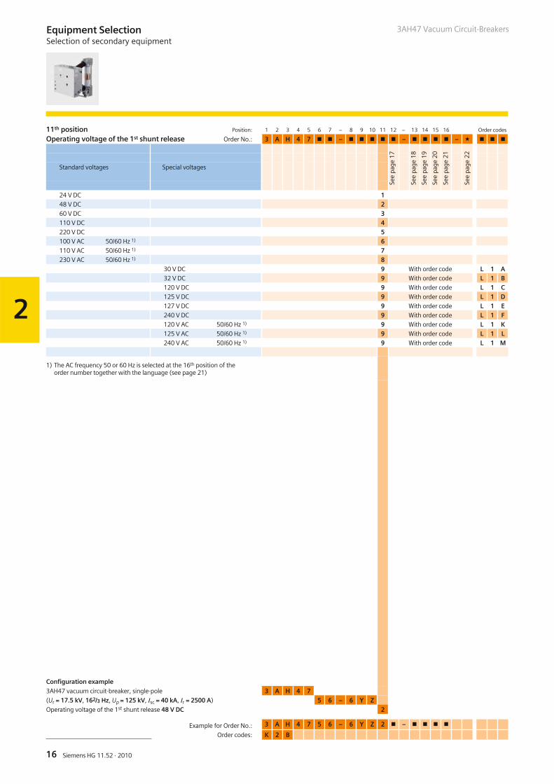
11th position Position: 1 2 3 4 5 6 7 – 8 9 10 11 12 – 13 14 15 16 Order codes
Operating voltage of the 1st shunt release Order No.: 3 A H 4 7 � � – � � � � � – � � � � – � � � �
24 V DC 148 V DC 260 V DC 3110 V DC 4220 V DC 5100 V AC 50/60 Hz 1) 6110 V AC 50/60 Hz 1) 7230 V AC 50/60 Hz 1) 8
30 V DC 9 With order code L 1 A32 V DC 9 With order code L 1 B120 V DC 9 With order code L 1 C125 V DC 9 With order code L 1 D127 V DC 9 With order code L 1 E240 V DC 9 With order code L 1 F120 V AC 50/60 Hz 1) 9 With order code L 1 K125 V AC 50/60 Hz 1) 9 With order code L 1 L240 V AC 50/60 Hz 1) 9 With order code L 1 M
1) The AC frequency 50 or 60 Hz is selected at the 16th position of theorder number together with the language (see page 21)
Configuration example
3AH47 vacuum circuit-breaker, single-pole 3 A H 4 7
(Ur = 17.5 kV, 162/3 Hz, Up = 125 kV, Isc = 40 kA, Ir = 2500 A) 5 6 – 6 Y Z
Operating voltage of the 1st shunt release 48 V DC 2
Standard voltages Special voltages
Example for Order No.: 3 A H 4 7 5 6 – 6 Y Z 2 � – � � � �
Order codes: K 2 B
See
page
17
See
page
18
See
page
19
See
page
20
See
page
21
See
page
22
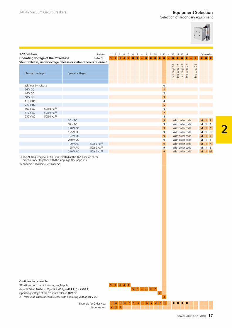
12th position Position: 1 2 3 4 5 6 7 – 8 9 10 11 12 – 13 14 15 16 Order codes
Operating voltage of the 2nd release Order No.: 3 A H 4 7 � � – � � � � � – � � � � – � � � �
Shunt release, undervoltage release or instantaneous release 2)
Without 2nd release 024 V DC 148 V DC 260 V DC 3110 V DC 4220 V DC 5100 V AC 50/60 Hz 1) 6110 V AC 50/60 Hz 1) 7230 V AC 50/60 Hz 1) 8
30 V DC 9 With order code M 1 A
32 V DC 9 With order code M 1 B
120 V DC 9 With order code M 1 C
125 V DC 9 With order code M 1 D
127 V DC 9 With order code M 1 E
240 V DC 9 With order code M 1 F
120 V AC 50/60 Hz 1) 9 With order code M 1 K
125 V AC 50/60 Hz 1) 9 With order code M 1 L
240 V AC 50/60 Hz 1) 9 With order code M 1 M
1) The AC frequency 50 or 60 Hz is selected at the 16th position of theorder number together with the language (see page 21)
2) 60 V DC, 110 V DC and 220 V DC
Configuration example
3AH47 vacuum circuit-breaker, single-pole 3 A H 4 7
(Ur = 17.5 kV, 162/3 Hz, Up = 125 kV, Isc = 40 kA, Ir = 2500 A) 5 6 – 6 Y Z
Operating voltage of the 1st shunt release 48 V DC 2
2nd release as instantaneous release with operating voltage 60 V DC 3
See
page
18
See
page
19
See
page
20
See
page
21
See
page
22
2
17Siemens HG 11.52 · 2010
3AH47 Vacuum Circuit-Breakers
Standard voltages Special voltages
Example for Order No.: 3 A H 4 7 5 6 – 6 Y Z 2 3 – � � � �
Order codes: K 2 B
Equipment SelectionSelection of secondary equipment
2
18 Siemens HG 11.52 · 2010
3AH47 Vacuum Circuit-Breakers
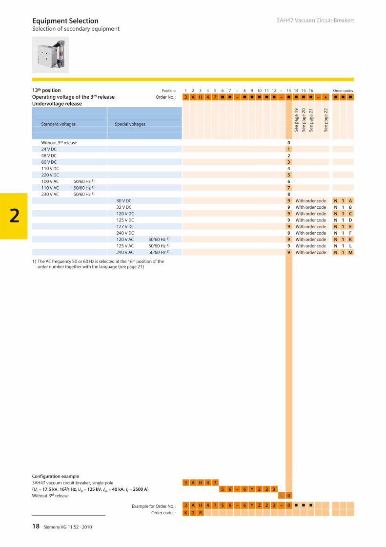
13th position Position: 1 2 3 4 5 6 7 – 8 9 10 11 12 – 13 14 15 16 Order codes
Operating voltage of the 3rd release Order No.: 3 A H 4 7 � � – � � � � � – � � � � – � � � �
Undervoltage release
Without 3rd release 024 V DC 148 V DC 260 V DC 3110 V DC 4220 V DC 5100 V AC 50/60 Hz 1) 6110 V AC 50/60 Hz 1) 7230 V AC 50/60 Hz 1) 8
30 V DC 9 With order code N 1 A32 V DC 9 With order code N 1 B120 V DC 9 With order code N 1 C125 V DC 9 With order code N 1 D127 V DC 9 With order code N 1 E240 V DC 9 With order code N 1 F120 V AC 50/60 Hz 1) 9 With order code N 1 K125 V AC 50/60 Hz 1) 9 With order code N 1 L240 V AC 50/60 Hz 1) 9 With order code N 1 M
1) The AC frequency 50 or 60 Hz is selected at the 16th position of theorder number together with the language (see page 21)
Configuration example
3AH47 vacuum circuit-breaker, single-pole 3 A H 4 7
(Ur = 17.5 kV, 162/3 Hz, Up = 125 kV, Isc = 40 kA, Ir = 2500 A) 5 6 – 6 Y Z 2 3
Without 3rd release – 0
Standard voltages Special voltages
See
page
19
See
page
20
See
page
21
See
page
22
Example for Order No.: 3 A H 4 7 5 6 – 6 Y Z 2 3 – 0 � � �
Order codes: K 2 B
Equipment SelectionSelection of secondary equipment
2
19Siemens HG 11.52 · 2010
3AH47 Vacuum Circuit-Breakers
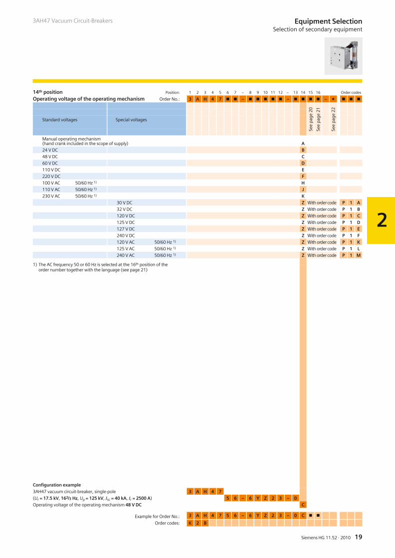
14th position Position: 1 2 3 4 5 6 7 – 8 9 10 11 12 – 13 14 15 16 Order codes
Operating voltage of the operating mechanism Order No.: 3 A H 4 7 � � – � � � � � – � � � � – � � � �
Manual operating mechanism(hand crank included in the scope of supply) A24 V DC B48 V DC C60 V DC D110 V DC E220 V DC F100 V AC 50/60 Hz 1) H110 V AC 50/60 Hz 1) J230 V AC 50/60 Hz 1) K
30 V DC Z With order code P 1 A32 V DC Z With order code P 1 B120 V DC Z With order code P 1 C125 V DC Z With order code P 1 D127 V DC Z With order code P 1 E240 V DC Z With order code P 1 F120 V AC 50/60 Hz 1) Z With order code P 1 K125 V AC 50/60 Hz 1) Z With order code P 1 L240 V AC 50/60 Hz 1) Z With order code P 1 M
1) The AC frequency 50 or 60 Hz is selected at the 16th position of theorder number together with the language (see page 21)
Configuration example
3AH47 vacuum circuit-breaker, single-pole 3 A H 4 7
(Ur = 17.5 kV, 162/3 Hz, Up = 125 kV, Isc = 40 kA, Ir = 2500 A) 5 6 – 6 Y Z 2 3 – 0
Operating voltage of the operating mechanism 48 V DC C
Standard voltages Special voltages
Example for Order No.: 3 A H 4 7 5 6 – 6 Y Z 2 3 – 0 C � �
Order codes: K 2 B
See
page
20
See
page
21
See
page
22
Equipment SelectionSelection of secondary equipment
2
20 Siemens HG 11.52 · 2010
3AH47 Vacuum Circuit-Breakers
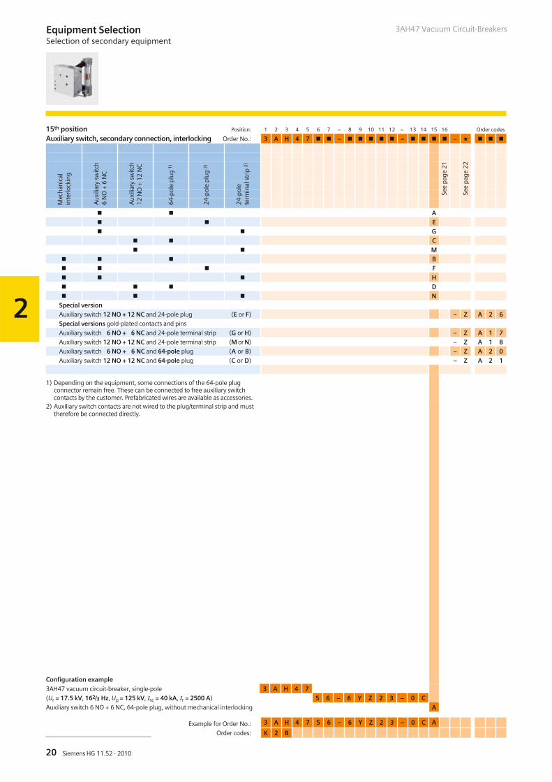
15th position Position: 1 2 3 4 5 6 7 – 8 9 10 11 12 – 13 14 15 16 Order codes
Auxiliary switch, secondary connection, interlocking Order No.: 3 A H 4 7 � � – � � � � � – � � � � – � � � �
� � A� � E� � G
� � C� � M
� � � B� � � F� � � H� � � D� � � N
Special versionAuxiliary switch 12 NO + 12 NC and 24-pole plug (E or F) – Z A 2 6Special versions gold-plated contacts and pins
Auxiliary switch 6 NO + 6 NC and 24-pole terminal strip (G or H) – Z A 1 7Auxiliary switch 12 NO + 12 NC and 24-pole terminal strip (M or N) – Z A 1 8Auxiliary switch 6 NO + 6 NC and 64-pole plug (A or B) – Z A 2 0
Auxiliary switch 12 NO + 12 NC and 64-pole plug (C or D) – Z A 2 1
1) Depending on the equipment, some connections of the 64-pole plugconnector remain free. These can be connected to free auxiliary switchcontacts by the customer. Prefabricated wires are available as accessories.
2) Auxiliary switch contacts are not wired to the plug/terminal strip and musttherefore be connected directly.
Mec
hani
cal
inte
rlock
ing
Aux
iliar
ysw
itch
6N
O+
6N
C
Aux
iliar
ysw
itch
12N
O+
12N
C
64-p
ole
plug
1)
24-p
ole
plug
2)
24-p
ole
term
inal
strip
2)
See
page
21
See
page
22
Configuration example
3AH47 vacuum circuit-breaker, single-pole 3 A H 4 7
(Ur = 17.5 kV, 162/3 Hz, Up = 125 kV, Isc = 40 kA, Ir = 2500 A) 5 6 – 6 Y Z 2 3 – 0 C
Auxiliary switch 6 NO + 6 NC, 64-pole plug, without mechanical interlocking A
Example for Order No.: 3 A H 4 7 5 6 – 6 Y Z 2 3 – 0 C A
Order codes: K 2 B
Equipment SelectionSelection of secondary equipment
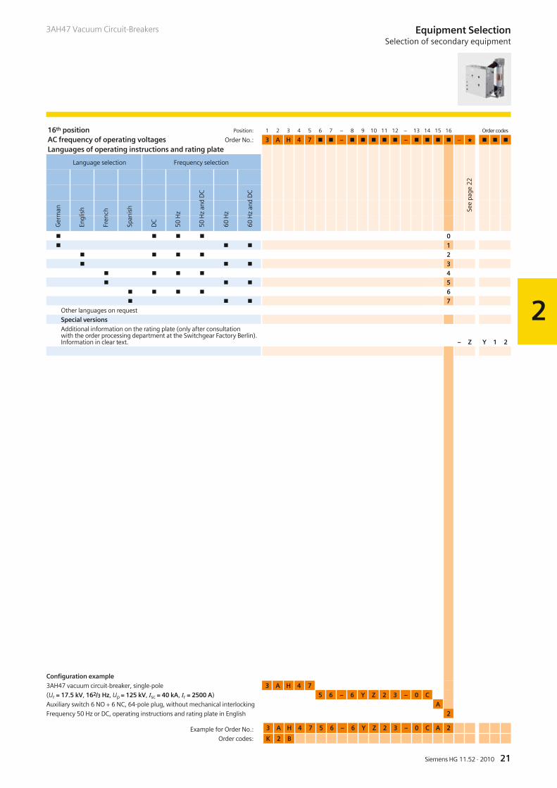
16th position Position: 1 2 3 4 5 6 7 – 8 9 10 11 12 – 13 14 15 16 Ordercodes
AC frequency of operating voltages Order No.: 3 A H 4 7 � � – � � � � � – � � � � – � � � �
Languages of operating instructions and rating plate
� � � � 0� � � 1
� � � � 2� � � 3
� � � � 4� � � 5
� � � � 6� � � 7
Other languages on request
Special versionsAdditional information on the rating plate (only after consultationwith the order processing department at the Switchgear Factory Berlin).Information in clear text. – Z Y 1 2
Configuration example
3AH47 vacuum circuit-breaker, single-pole 3 A H 4 7
(Ur = 17.5 kV, 162/3 Hz, Up = 125 kV, Isc = 40 kA, Ir = 2500 A) 5 6 – 6 Y Z 2 3 – 0 C
Auxiliary switch 6 NO + 6 NC, 64-pole plug, without mechanical interlocking A
Frequency 50 Hz or DC, operating instructions and rating plate in English 2
2
21Siemens HG 11.52 · 2010
3AH47 Vacuum Circuit-Breakers
See
page
22
Equipment SelectionSelection of secondary equipment
Ger
man
Engl
ish
Fren
ch
Span
ish
DC
50H
z
50H
zan
dD
C
60H
z
60H
zan
dD
C
Language selection Frequency selection
Example for Order No.: 3 A H 4 7 5 6 – 6 Y Z 2 3 – 0 C A 2
Order codes: K 2 B
2
22 Siemens HG 11.52 · 2010
3AH47 Vacuum Circuit-Breakers
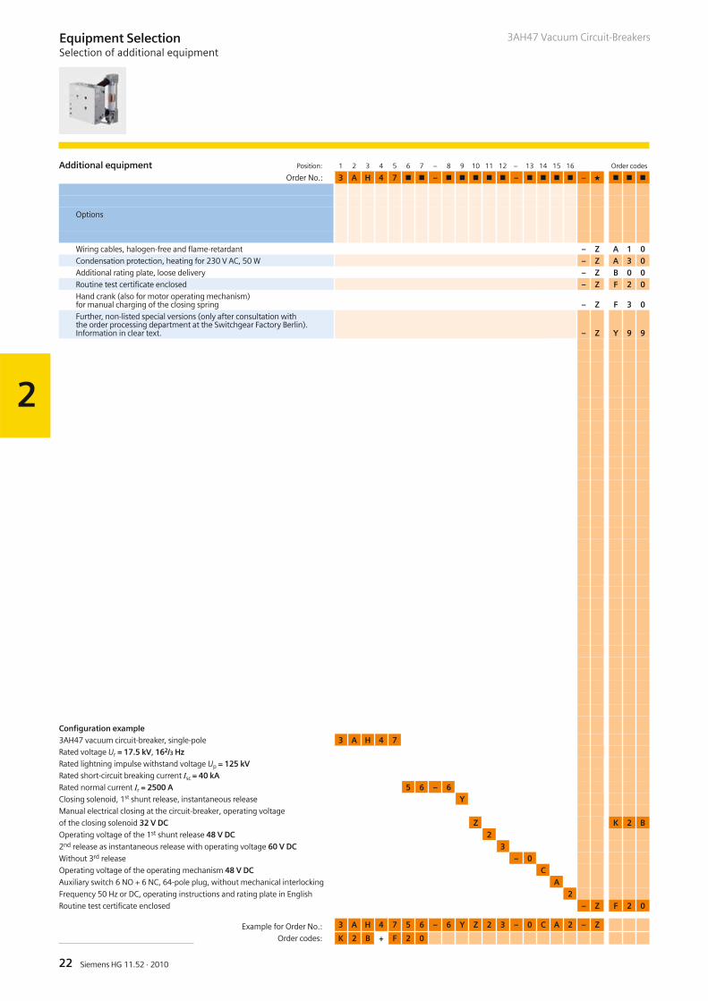
Additional equipment Position: 1 2 3 4 5 6 7 – 8 9 10 11 12 – 13 14 15 16 Order codes
Order No.: 3 A H 4 7 � � – � � � � � – � � � � – � � � �
Wiring cables, halogen-free and flame-retardant – Z A 1 0Condensation protection, heating for 230 V AC, 50 W – Z A 3 0Additional rating plate, loose delivery – Z B 0 0Routine test certificate enclosed – Z F 2 0Hand crank (also for motor operating mechanism)for manual charging of the closing spring – Z F 3 0Further, non-listed special versions (only after consultation withthe order processing department at the Switchgear Factory Berlin).Information in clear text. – Z Y 9 9
Configuration example3AH47 vacuum circuit-breaker, single-pole 3 A H 4 7Rated voltage Ur = 17.5 kV, 162/3 HzRated lightning impulse withstand voltage Up = 125 kVRated short-circuit breaking current Isc = 40 kARated normal current Ir = 2500 A 5 6 – 6Closing solenoid, 1st shunt release, instantaneous release YManual electrical closing at the circuit-breaker, operating voltage
of the closing solenoid 32 V DC Z K 2 B
Operating voltage of the 1st shunt release 48 V DC 2
2nd release as instantaneous release with operating voltage 60 V DC 3
Without 3rd release – 0
Operating voltage of the operating mechanism 48 V DC C
Auxiliary switch 6 NO + 6 NC, 64-pole plug, without mechanical interlocking A
Frequency 50 Hz or DC, operating instructions and rating plate in English 2
Routine test certificate enclosed – Z F 2 0
Options
Example for Order No.: 3 A H 4 7 5 6 – 6 Y Z 2 3 – 0 C A 2 – Z
Order codes: K 2 B + F 2 0
Equipment SelectionSelection of additional equipment
2
23Siemens HG 11.52 · 2010
3AH47 Vacuum Circuit-Breakers Equipment SelectionAccessories and spare parts
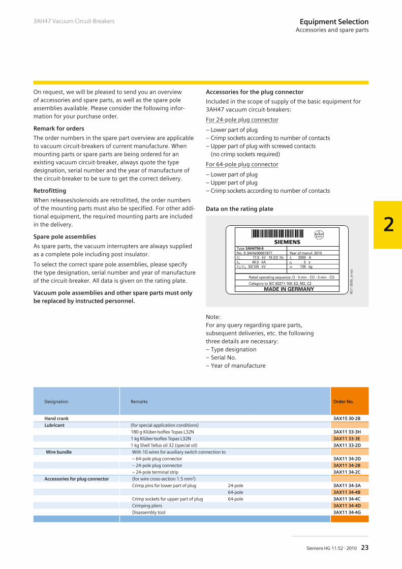
On request, we will be pleased to send you an overviewof accessories and spare parts, as well as the spare poleassemblies available. Please consider the following infor-mation for your purchase order.
Remark for orders
The order numbers in the spare part overview are applicableto vacuum circuit-breakers of current manufacture. Whenmounting parts or spare parts are being ordered for anexisting vacuum circuit-breaker, always quote the typedesignation, serial number and the year of manufacture ofthe circuit-breaker to be sure to get the correct delivery.
Retrofitting
When releases/solenoids are retrofitted, the order numbersof the mounting parts must also be specified. For other addi-tional equipment, the required mounting parts are includedin the delivery.
Spare pole assemblies
As spare parts, the vacuum interrupters are always suppliedas a complete pole including post insulator.
To select the correct spare pole assemblies, please specifythe type designation, serial number and year of manufactureof the circuit-breaker. All data is given on the rating plate.
Vacuum pole assemblies and other spare parts must onlybe replaced by instructed personnel.
Accessories for the plug connector
Included in the scope of supply of the basic equipment for3AH47 vacuum circuit-breakers:
For 24-pole plug connector
– Lower part of plug– Crimp sockets according to number of contacts– Upper part of plug with screwed contacts
(no crimp sockets required)
For 64-pole plug connector
– Lower part of plug– Upper part of plug– Crimp sockets according to number of contacts
����
����
&���
���
Data on the rating plate
Note:For any query regarding spare parts,subsequent deliveries, etc. the followingthree details are necessary:– Type designation– Serial No.– Year of manufacture
Designation Remarks Order No.
Hand crank 3AX15 30-2BLubricant (for special application conditions)
180 g Klüber-Isoflex Topas L32N 3AX11 33-3H1 kg Klüber-Isoflex Topas L32N 3AX11 33-3E1 kg Shell Tellus oil 32 (special oil) 3AX11 33-2D
Wire bundle With 10 wires for auxiliary switch connection to
– 64-pole plug connector 3AX11 34-2D– 24-pole plug connector 3AX11 34-2B– 24-pole terminal strip 3AX11 34-2C
Accessories for plug connector (for wire cross-section 1.5 mm2)
Crimp pins for lower part of plug 24-pole 3AX11 34-3A64-pole 3AX11 34-4B
Crimp sockets for upper part of plug 64-pole 3AX11 34-4CCrimping pliers 3AX11 34-4DDisassembly tool 3AX11 34-4G
24 Siemens HG 11.52 · 2010
R-HG
11-2
13.ti
f
3AH47 Vacuum Circuit-Breakers
25Siemens HG 11.52 · 2010
3
3AH47 Vacuum Circuit-Breakers
Operating shaft and operating rod
Post insulator and pole assembly
Contents Page
Technical Data
Electrical data, dimensions and weights:
Voltage level 17.5 kV
Voltage level 27.5 kV (single-pole)
Voltage level 27.5 kV (two-pole)
Circuit diagrams
Operating times
Short-circuit protection of motors
Consumption data of releases
25
26
26
26
30
32
32
32
Technical DataContents
R-HG
11-2
11.ti
fR-
HG11
-212
.tif
17.5 kV162/3 Hz
Ir tk Isc Ima Up Ud
A s kA % kA kA kV kV mV mm mm mm kg
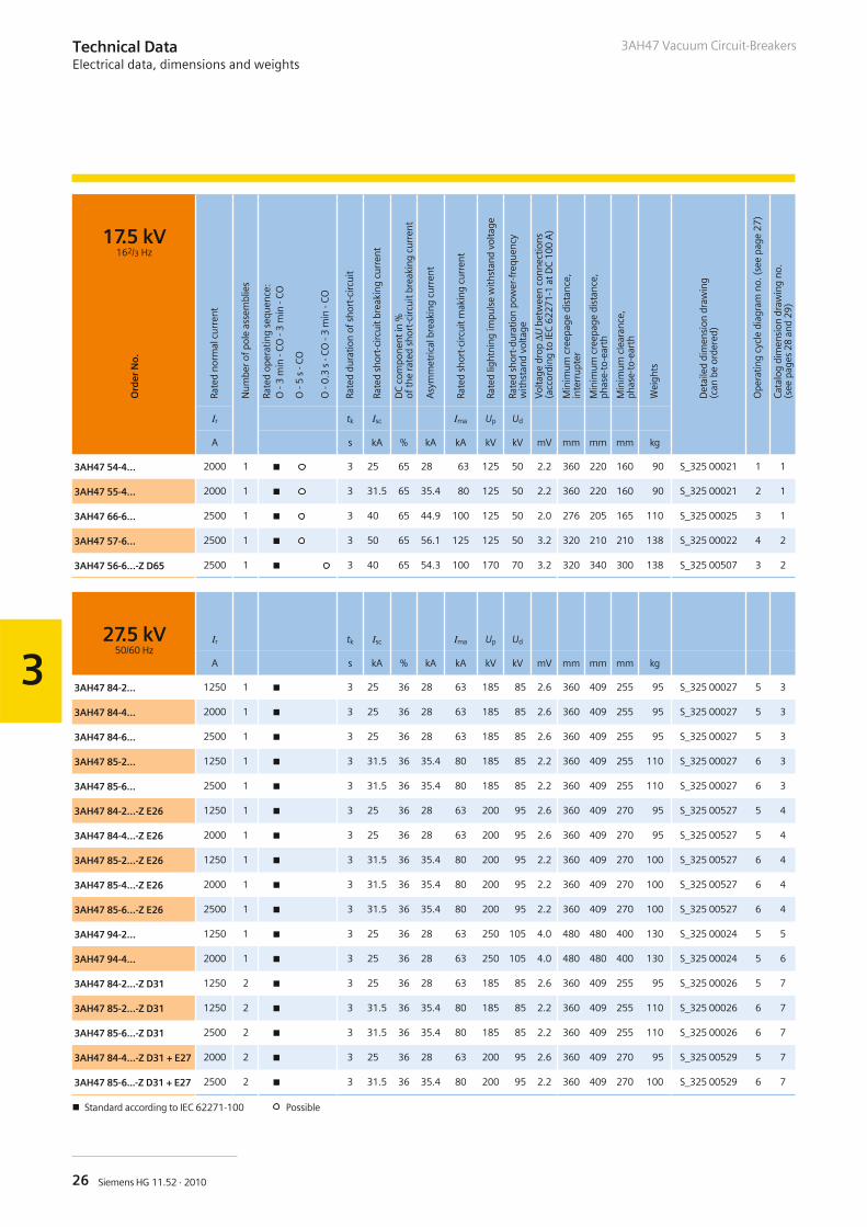
3AH47 54-4… 2000 1 � 3 25 65 28 63 125 50 2.2 360 220 160 90 S_325 00021 1 1
3AH47 55-4… 2000 1 � 3 31.5 65 35.4 80 125 50 2.2 360 220 160 90 S_325 00021 2 1
3AH47 66-6… 2500 1 � 3 40 65 44.9 100 125 50 2.0 276 205 165 110 S_325 00025 3 1
3AH47 57-6… 2500 1 � 3 50 65 56.1 125 125 50 3.2 320 210 210 138 S_325 00022 4 2
3AH47 56-6…-Z D65 2500 1 � 3 40 65 54.3 100 170 70 3.2 320 340 300 138 S_325 00507 3 2
27.5 kV50/60 Hz
Ir tk Isc Ima Up Ud
A s kA % kA kA kV kV mV mm mm mm kg
3AH47 84-2… 1250 1 � 3 25 36 28 63 185 85 2.6 360 409 255 95 S_325 00027 5 3
3AH47 84-4… 2000 1 � 3 25 36 28 63 185 85 2.6 360 409 255 95 S_325 00027 5 3
3AH47 84-6… 2500 1 � 3 25 36 28 63 185 85 2.6 360 409 255 95 S_325 00027 5 3
3AH47 85-2… 1250 1 � 3 31.5 36 35.4 80 185 85 2.2 360 409 255 110 S_325 00027 6 3
3AH47 85-6… 2500 1 � 3 31.5 36 35.4 80 185 85 2.2 360 409 255 110 S_325 00027 6 3
3AH47 84-2…-Z E26 1250 1 � 3 25 36 28 63 200 95 2.6 360 409 270 95 S_325 00527 5 4
3AH47 84-4…-Z E26 2000 1 � 3 25 36 28 63 200 95 2.6 360 409 270 95 S_325 00527 5 4
3AH47 85-2…-Z E26 1250 1 � 3 31.5 36 35.4 80 200 95 2.2 360 409 270 100 S_325 00527 6 4
3AH47 85-4…-Z E26 2000 1 � 3 31.5 36 35.4 80 200 95 2.2 360 409 270 100 S_325 00527 6 4
3AH47 85-6…-Z E26 2500 1 � 3 31.5 36 35.4 80 200 95 2.2 360 409 270 100 S_325 00527 6 4
3AH47 94-2… 1250 1 � 3 25 36 28 63 250 105 4.0 480 480 400 130 S_325 00024 5 5
3AH47 94-4… 2000 1 � 3 25 36 28 63 250 105 4.0 480 480 400 130 S_325 00024 5 6
3AH47 84-2…-Z D31 1250 2 � 3 25 36 28 63 185 85 2.6 360 409 255 95 S_325 00026 5 7
3AH47 85-2…-Z D31 1250 2 � 3 31.5 36 35.4 80 185 85 2.2 360 409 255 110 S_325 00026 6 7
3AH47 85-6…-Z D31 2500 2 � 3 31.5 36 35.4 80 185 85 2.2 360 409 255 110 S_325 00026 6 7
3AH47 84-4…-Z D31 + E27 2000 2 � 3 25 36 28 63 200 95 2.6 360 409 270 95 S_325 00529 5 7
3AH47 85-6...-Z D31 + E27 2500 2 � 3 31.5 36 35.4 80 200 95 2.2 360 409 270 100 S_325 00529 6 7
26 Siemens HG 11.52 · 2010
3
3AH47 Vacuum Circuit-Breakers
Ord
erN
o.
Rate
dno
rmal
curr
ent
Num
bero
fpol
eas
sem
blie
s
Rate
dop
erat
ing
sequ
ence
:O
-3m
in-C
O-3
min
-CO
O-5
s-C
O
O-0
.3s
-CO
-3m
in-C
O
Rate
ddu
ratio
nof
shor
t-ci
rcui
t
Rate
dsh
ort-
circ
uitb
reak
ing
curr
ent
DC
com
pone
ntin
%of
the
rate
dsh
ort-
circ
uitb
reak
ing
curr
ent
Asy
mm
etric
albr
eaki
ngcu
rren
t
Rate
dsh
ort-
circ
uitm
akin
gcu
rren
t
Rate
dlig
htni
ngim
puls
ew
ithst
and
volta
ge
Rate
dsh
ort-
dura
tion
pow
er-f
requ
ency
with
stan
dvo
ltage
Vol
tage
drop
ΔUbe
twee
nco
nnec
tions
(acc
ordi
ngto
IEC
6227
1-1
atD
C10
0A
)
Min
imum
cree
page
dist
ance
,in
terr
upte
r
Min
imum
cree
page
dist
ance
,ph
ase-
to-e
arth
Min
imum
clea
ranc
e,ph
ase-
to-e
arth
Wei
ghts
Det
aile
ddi
men
sion
draw
ing
(can
beor
dere
d)
Ope
ratin
gcy
cle
diag
ram
no.(
see
page
27)
Cat
alog
dim
ensi
ondr
awin
gno
.(s
eepa
ges
28an
d29
)
Technical DataElectrical data, dimensions and weights
� Standard according to IEC 62271-100 Possible
27Siemens HG 11.52 · 2010
3
3AH47 Vacuum Circuit-Breakers Technical DataElectrical data, dimensions and weights
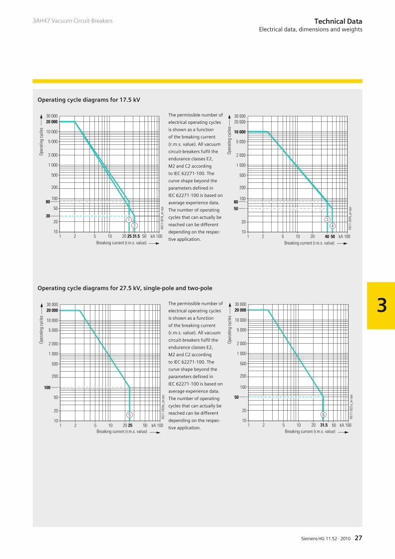
Operating cycle diagrams for 17.5 kV
Operating cycle diagrams for 27.5 kV, single-pole and two-pole
The permissible number of
electrical operating cycles
is shown as a function
of the breaking current
(r.m.s. value). All vacuum
circuit-breakers fulfil the
endurance classes E2,
M2 and C2 according
to IEC 62271-100. The
curve shape beyond the
parameters defined in
IEC 62271-100 is based on
average experience data.
The number of operating
cycles that can actually be
reached can be different
depending on the respec-
tive application.
������
����
����
����
���
���
��
��� � � �� �� '���
����
����
����
��
���
���
�����
�����
��
�
( ��'��)�� ���* ����+����,
-�
����
)�.
���
��
( ��'��)�� ���* ����+����,
�����
����
����
����
���
���
���
��
��� � � �� '���
����
����
����
�
���
��
�����
������
��
��
-�
����
)�.
���
����( ��'��)�� ���* ����+����,
������
-�
����
)�.
���
����
����
����
���
���
���
��
��� � � �� �� '���
����
����
���
�
���
��
��
�����
�����
��
��
�
��
��
����
����
����
���
���
���
��
��� � � �� '���
����
����
����
��
���
�����
��
������
�����
�
( ��'��)�� ���* ����+����,
-�
����
)�.
���
��
28 Siemens HG 11.52 · 2010
3
3AH47 Vacuum Circuit-BreakersTechnical DataElectrical data, dimensions and weights
�&�
����
�
���
����
����
���
���
���
��
���
���
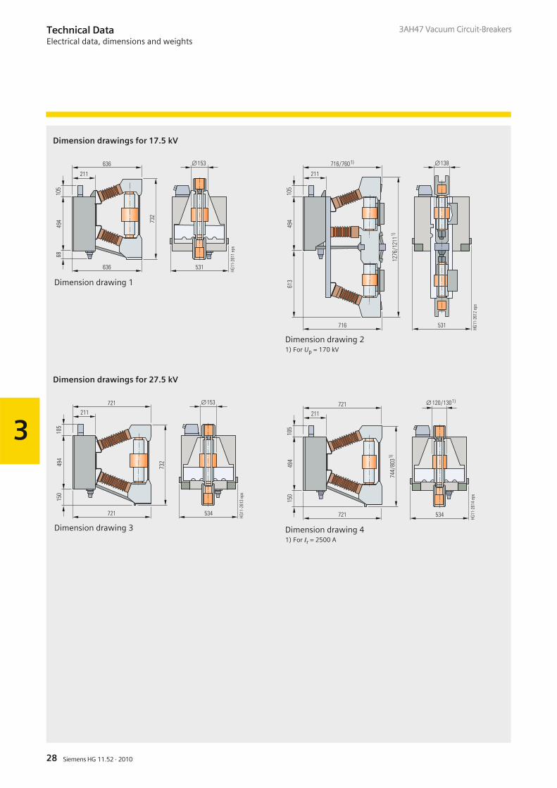
Dimension drawing 1�&
���
���
�
���
����
����
���
���
��
���
/���
���
��/����
���
Dimension drawing 21) For Up = 170 kV
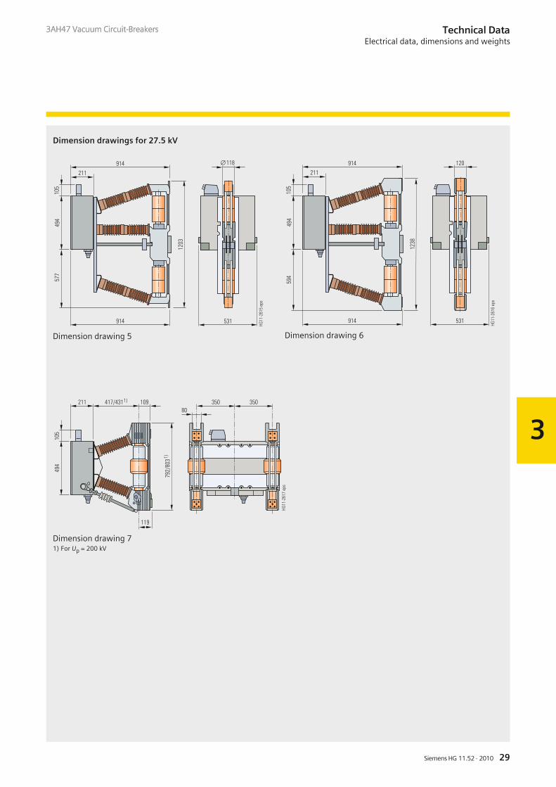
Dimension drawings for 17.5 kV
�&�
���
���
���
����
����
���
���
��
��
���
��
Dimension drawing 3
���/�����
����
����
���
���
�&�
���
���
���
��
��/
����
�
��
Dimension drawing 41) For Ir = 2500 A
Dimension drawings for 27.5 kV
3AH47 Vacuum Circuit-Breakers
29Siemens HG 11.52 · 2010
3
3AH47 Vacuum Circuit-Breakers Technical DataElectrical data, dimensions and weights
�&�
�
���
���
����
����
���
���
&��
����
&��
���
Dimension drawing 5
�&�
�&�
���
���
����
����
���
���
&��
����
&��
���
Dimension drawing 6
����
����
��
�&�
���
���
��&
������
&�/
����
�
��/����� ��&��
Dimension drawing 71) For Up = 200 kV
Dimension drawings for 27.5 kV
3AH47 Vacuum Circuit-Breakers
30 Siemens HG 11.52 · 2010
3
3AH47 Vacuum Circuit-Breakers
���� ����
0
���� ���� ��� ���� ����
�1
��
�2�
��� ���
�2�
3�0�
���������
����
����
����
�
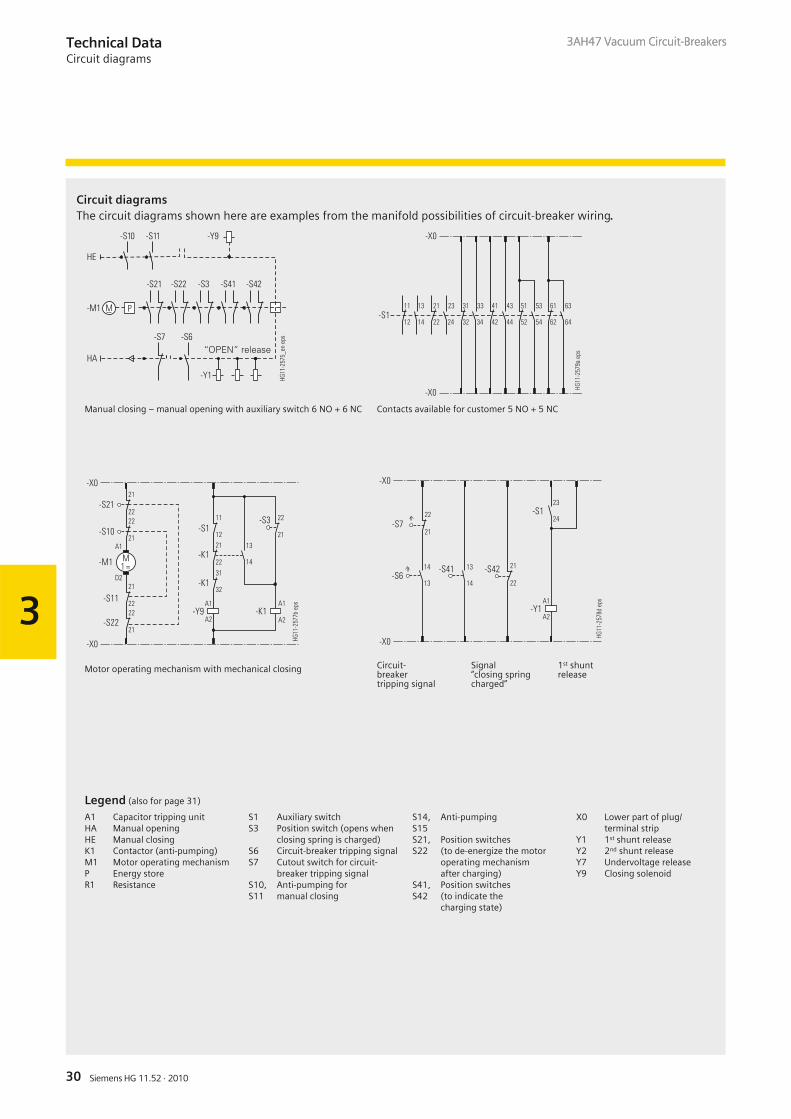
Manual closing – manual opening with auxiliary switch 6 NO + 6 NC
��
��
��
�����
��
��
��
��
��
��
��
��
��
��
��
��
��
��
��
��
��
��
��
��
�4�
�4� ����
���
&��
�
Contacts available for customer 5 NO + 5 NC
��
����
5�
������
��
�4�
��
��
����
��
��
��
����
��
��
��
��
��
������
��
��
�6�
�6�
�6�
����
���
����
����
�4�
�
����
���
��
� ��
����&
�7
Motor operating mechanism with mechanical closing
Technical DataCircuit diagrams
Legend (also for page 31)
A1 Capacitor tripping unitHA Manual openingHE Manual closingK1 Contactor (anti-pumping)M1 Motor operating mechanismP Energy storeR1 Resistance
S1 Auxiliary switchS3 Position switch (opens when
closing spring is charged)S6 Circuit-breaker tripping signalS7 Cutout switch for circuit-
breaker tripping signalS10, Anti-pumping forS11 manual closing
S14, Anti-pumpingS15S21, Position switchesS22 (to de-energize the motor
operating mechanismafter charging)
S41, Position switchesS42 (to indicate the
charging state)
X0 Lower part of plug/terminal strip
Y1 1st shunt releaseY2 2nd shunt releaseY7 Undervoltage releaseY9 Closing solenoid
3AH47 Vacuum Circuit-Breakers
����
��
�4�
�4�
��
�����
��
��
��
��
��
��
���� ����
���
����
���
���
� ��
�����
Circuit- Signal 1st shuntbreaker “closing spring releasetripping signal charged”
Circuit diagramsThe circuit diagrams shown here are examples from the manifold possibilities of circuit-breaker wiring.
31Siemens HG 11.52 · 2010
3
3AH47 Vacuum Circuit-Breakers
��
��
��
�����
��
��
��
��
��
��
��
��
��
��
��
��
��
��
��
��
��
��
��
��
�
�
�
�
��
��
��
��
&�
&�
&�
&�
���
���
���
���
���
���
���
���
���
���
���
���
�4�
�4� ����
����
���
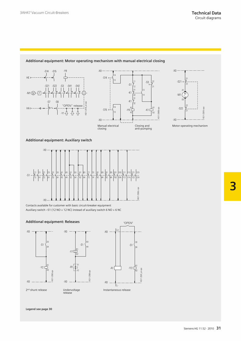
� Additional equipment: Auxiliary switch
Additional equipment: Releases
Technical DataCircuit diagrams
����
����
����
�
���� ����
0
���� ���� ��� ���� ����
�1
��
�2�
��� ���
�2�
3�0�
���������
�4�
��
��
��
����
��
��
��
��
��
��
��
������
��
��
�6�
�6�
��& �6�
�4�
��
������
��
������
����
����
���
�
Additional equipment: Motor operating mechanism with manual electrical closing
Manual electrical Closing andclosing anti-pumping
������
��
�4�
��
������
�4�
����
����
���
�
��
5�
��� ��7
Motor operating mechanism
2nd shunt release Undervoltage Instantaneous releaserelease
Contacts available for customer with basic circuit-breaker equipment
Auxiliary switch –S1 (12 NO + 12 NC) instead of auxiliary switch 6 NO + 6 NC
3AH47 Vacuum Circuit-Breakers
�����
��
����
����
���
�4�
�4�
�����
��
�����
��
����
�
��5�
5�
����
����
���
�4�
�4�
� 8
������
�����
��
����
����
����
�
���
���
�2���
�����
��
��
Legend see page 30
32 Siemens HG 11.52 · 2010
3
3AH47 Vacuum Circuit-Breakers
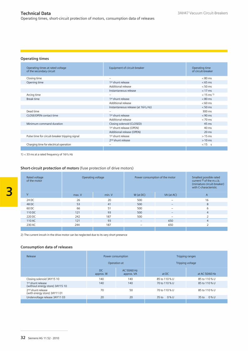
Operating times
Operating times at rated voltageof the secondary circuit
Equipment of circuit-breaker Operating timeof circuit-breaker
Closing time – < 80 ms
Opening time 1st shunt release < 65 ms
Additional release < 50 ms
Instantaneous release < 17 ms
Arcing time – < 15 ms 1)
Break time 1st shunt release < 80 ms
Additional release < 60 ms
Instantaneous release (at 162/3 Hz) < 50 ms
Dead time – 300 ms
CLOSE/OPEN contact time 1st shunt release < 90 ms
Additional release < 70 ms
Minimum command duration Closing solenoid (CLOSED) 45 ms
1st shunt release (OPEN) 40 ms
Additional release (OPEN) 20 ms
Pulse time for circuit-breaker tripping signal 1st shunt release > 15 ms
2nd shunt release > 10 ms
Charging time for electrical operation – < 15 s
1) < 33 ms at a rated frequency of 162/3 Hz
Short-circuit protection of motors (fuse protection of drive motors)
Rated voltageof the motor
Operating voltage Power consumption of the motor Smallest possible ratedcurrent 2) of the m.c.b.(miniature circuit-breaker)with C-characteristic
V max. V min. V W (at DC) VA (at AC) A
24 DC 26 20 500 – 16
48 DC 53 41 500 – 8
60 DC 66 51 500 – 6
110 DC 121 93 500 – 4
220 DC 242 187 500 – 2
110 AC 121 93 – 650 4
230 AC 244 187 – 650 2
2) The current inrush in the drive motor can be neglected due to its very short presence
Consumption data of releases
Release Power consumption
Operation at
Tripping ranges
Tripping voltage
DCapprox. W
AC 50/60 Hzapprox. VA at DC at AC 50/60 Hz
Closing solenoid 3AY15 10 140 140 85 to 110 % U 85 to 110 % U1st shunt release(without energy store) 3AY15 10
140 140 70 to 110 % U 85 to 110 % U
2nd shunt release(with energy store) 3AY11 01
70 50 70 to 110 % U 85 to 110 % U
Undervoltage release 3AY11 03 20 20 35 to 0 % U 35 to 0 % U
Technical DataOperating times, short-circuit protection of motors, consumption data of releases
3AH47 Vacuum Circuit-Breakers
33Siemens HG 11.52 · 2010
4
3AH47 Vacuum Circuit-Breakers
Contents Page
Annex
Inquiry form
Configuration instructions
Configuration aid
33
34
35
AnnexContents
Foldout page
Switchgear Factory in Berlin, Germany
Brandenburg Gate, Berlin, Germany
R-HG
11-1
81.ti
fR-
HG11
-180
.eps
3AH47 Vacuum Circuit-Breakers
34 Siemens HG 11.52 · 2010
4
3AH47 Vacuum Circuit-BreakersAnnexInquiry form
Inquiry concerning
� 3AH47 circuit-breaker
Please
� Submit an offer� Call us� Visit us
Your address
Company
Dept.
Name
Street
Postal code/city
Phone
Fax
Siemens AG
Dept.
Name
Street
Postal code/city
Fax
Technical dataOther values
Rated voltage � 17.5 kV
� 27.5 kV
� 162/3 Hz
� 50/60 Hz � _ _ _ kV
Rated lightning impulse
withstand voltage
� 125 kV
� 200 kV
� 170 kV
� 250 kV
�185 kV
� _ _ _ kV
Rated short-duration
power-frequency withstand voltage
� 50 kV
� 95 kV
� 70 kV
� 105 kV
� 85 kV
� _ _ _ kV
Rated short-circuit
breaking current
� 25 kA
� 40 kA
� 31.5 kA
� 50 kA � _ _ _ kA
Rated normal current � 1250 A
� 2500 A
� 2000 A
� _ _ _ A
Number of poles � Single-pole � Two-pole
Secondary equipment
For possible combinations see pages 14 to 21
Circuit-breaker equipment
� Manual mechanical closing
� Manual electrical closing
� Manual operating mechanism
Motor operating mechanism � _ _ _ V DC � _ _ _ V AC, _ _ _ Hz
Closing solenoid � _ _ _ V DC � _ _ _ V AC, _ _ _ Hz
1st shunt release � _ _ _ V DC � _ _ _ V AC, _ _ _ Hz
2nd shunt release � _ _ _ V DC � _ _ _ V AC, _ _ _ Hz
Instantaneous release � 60 V DC � 110 V DC � 220 V DC
Undervoltage release � _ _ _ V DC � _ _ _ V AC, _ _ _ Hz
Auxiliary switch � 6 NO + 6 NC � 12 NO + 12 NC
Low-voltage connection � 24-pole
terminal strip
� 24-pole plug � 64-pole plug
� Mechanical interlocking
Operating instructions � English � German � French � Spanish
Application and other requirements
� Please check off _ _ _ Please fill in
3AH47 Vacuum Circuit-Breakers
Please copy, fill in and returnto your Siemens partner.
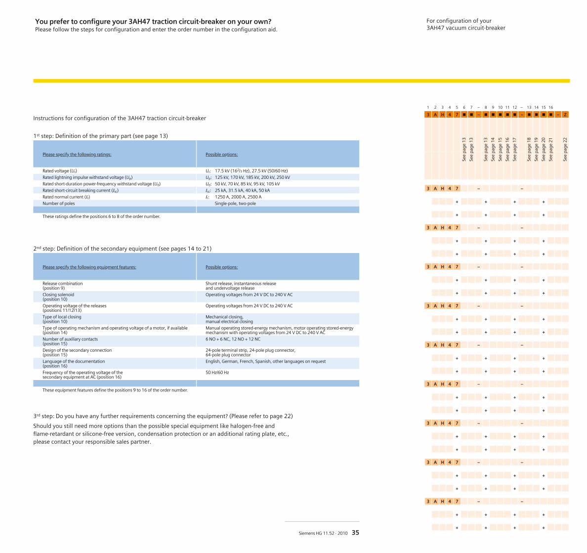
Instructions for configuration of the 3AH47 traction circuit-breaker
1st step: Definition of the primary part (see page 13)
Please specify the following ratings: Possible options:
Rated voltage (Ur) Ur: 17.5 kV (162/3 Hz), 27.5 kV (50/60 Hz)
Rated lightning impulse withstand voltage (Up) Up: 125 kV, 170 kV, 185 kV, 200 kV, 250 kV
Rated short-duration power-frequency withstand voltage (Ud) Ud: 50 kV, 70 kV, 85 kV, 95 kV, 105 kV
Rated short-circuit breaking current (Isc) Isc: 25 kA, 31.5 kA, 40 kA, 50 kA
Rated normal current (Ir) Ir: 1250 A, 2000 A, 2500 A
Number of poles Single-pole, two-pole
These ratings define the positions 6 to 8 of the order number.
2nd step: Definition of the secondary equipment (see pages 14 to 21)
Please specify the following equipment features: Possible options:
Release combination(position 9)
Shunt release, instantaneous releaseand undervoltage release
Closing solenoid(position 10)
Operating voltages from 24 V DC to 240 V AC
Operating voltage of the releases(positions 11/12/13)
Operating voltages from 24 V DC to 240 V AC
Type of local closing(position 10)
Mechanical closing,manual electrical closing
Type of operating mechanism and operating voltage of a motor, if available(position 14)
Manual operating stored-energy mechanism, motor operating stored-energymechanism with operating voltages from 24 V DC to 240 V AC
Number of auxiliary contacts(position 15)
6 NO + 6 NC, 12 NO + 12 NC
Design of the secondary connection(position 15)
24-pole terminal strip, 24-pole plug connector,64-pole plug connector
Language of the documentation(position 16)
English, German, French, Spanish, other languages on request
Frequency of the operating voltage of thesecondary equipment at AC (position 16)
50 Hz/60 Hz
These equipment features define the positions 9 to 16 of the order number.
3rd step: Do you have any further requirements concerning the equipment? (Please refer to page 22)
Should you still need more options than the possible special equipment like halogen-free andflame-retardant or silicone-free version, condensation protection or an additional rating plate, etc.,please contact your responsible sales partner.
For configuration of your3AH47 vacuum circuit-breaker
1 2 3 4 5 6 7 – 8 9 10 11 12 – 13 14 15 16
3 A H 4 7 � � – � � � � � – � � � � – Z
3 A H 4 7 – –
+ + + +
+ + + +
3 A H 4 7 – –
+ + + +
+ + + +
3 A H 4 7 – –
+ + + +
+ + + +
3 A H 4 7 – –
+ + + +
+ + + +
3 A H 4 7 – –
+ + + +
+ + + +
3 A H 4 7 – –
+ + + +
+ + + +
3 A H 4 7 – –
+ + + +
+ + + +
3 A H 4 7 – –
+ + + +
+ + + +
3 A H 4 7 – –
+ + + +
+ + + +
See
page
13
See
page
13
See
page
13
See
page
14
See
page
15
See
page
16
See
page
17
See
page
18
See
page
19
See
page
20
See
page
21
See
page
22
35Siemens HG 11.52 · 2010
You prefer to configure your 3AH47 traction circuit-breaker on your own?Please follow the steps for configuration and enter the order number in the configuration aid.
.
R-HG
11-1
74.ep
s
Published by and copyright © 2010:Siemens AGEnergy SectorFreyeslebenstrasse 191058 Erlangen, Germany
Siemens AGEnergy SectorPower Distribution DivisionMedium VoltageNonnendammallee 10413623 Berlin, Germany
For more information, please contact ourCustomer Support Center.Phone: +49 180 524 70 00Fax: +49 180 524 24 71(Charges depending on provider)E-mail: [email protected]
Order No. E50001-K1511-A521-A2-7600Printed in GermanyDispo 40402, c4bs 7470KG 05.10 1.0 38 En3600 / 24493
Printed on elementary chlorine-free bleached paper.
All rights reserved.If not stated otherwise on the individual pages of thiscatalog, we reserve the right to include modifications,especially regarding the stated values, dimensions and weights.Drawings are not binding.All product designations used are trademarks or productnames of Siemens AG or other suppliers.If not stated otherwise, all dimensions in thiscatalog are given in mm.
Subject to change without prior notice.The information in this document contains generaldescriptions of the technical options available, whichmay not apply in all cases. The required technicaloptions should therefore be specified in the contract.
www.siemens.com/energy