3b2 to ps.ps 1. - legislation.gov.uk
TRANSCRIPT
1998L0018 — EN — 17.05.2003 — 003.001 — 1
This document is meant purely as a documentation tool and the institutions do not assume any liability for its contents
►B COUNCIL DIRECTIVE 98/18/EC
of 17 March 1998
on safety rules and standards for passenger ships
(OJ L 144, 15.5.1998, p. 1)
Amended by:
Official Journal
No page date
►M1 Directive 2002/84/EC of the European Parliament and of the Council of5 November 2002
L 324 53 29.11.2002
►M2 Commission Directive 2002/25/EC of 5 March 2002 L 98 1 15.4.2002
►M3 Directive 2003/24/EC of the European Parliament and of the Council of14 April 2003
L 123 18 17.5.2003
Corrected by:
►C1 Corrigendum, OJ L 113, 12.5.2000, p. 55 (98/18/EC)

▼BCOUNCIL DIRECTIVE 98/18/EC
of 17 March 1998
on safety rules and standards for passenger ships
THE COUNCIL OF THE EUROPEAN UNION,
Having regard to the Treaty establishing the European Community, andin particular Article 84(2) thereof,
Having regard to the proposal from the Commission (1),
Having regard to the opinion of the Economic and SocialCommittee (2),
Acting in accordance with the procedure laid down in Article 189c ofthe Treaty (3),
(1) Whereas within the framework of the common transport policyfurther measures must be adopted to enhance safety in maritimetransport;
(2) Whereas the Community is seriously concerned about the latestshipping casualties in which passenger ships were involvedresulting in a massive loss of life; whereas persons usingpassenger ships and high speed passenger craft throughout theCommunity have the right to expect and to rely on an appro-priate level of safety on board;
(3) Whereas work equipment and personal protective equipment ofworkers are not covered by this Directive, because the provisionsof Council Directive 89/391/EEC of 12 June 1989 on the intro-duction of measures to encourage improvements in the safetyand health of workers at work (4) and the relevant provisions ofits relevant individual directives are applicable to the use of suchequipment on passenger ships engaged on domestic voyages;
(4) Whereas the provision of maritime passenger transport servicesbetween Member States has already been liberalised by Regula-tion (EEC) No 4055/86 (5); whereas the application of theprinciple of freedom to provide services to maritime transportwithin Member States (maritime cabotage), provided for byRegulation (EEC) No 3577/92 (6), will be completed throughoutthe Community within the next few years;
(5) Whereas to attain a high level of safety, and to remove barriersto trade, it is necessary to establish harmonised safety standardsat an appropriate level for passenger ships and craft operatingdomestic services; whereas standards for vessels operating inter-national voyages are being developed within the InternationalMaritime Organisation (IMO); whereas this Directive introducesprocedures to request action at IMO in order to bring in line thestandards for international voyages with the standards of thisDirective;
(6) Whereas, as proposed by the Commission in its communication‘A Common Policy on Safe Seas’, the Council, in its Resolutionof 8 June 1993 on a common policy on safe seas (7), and theEuropean Parliament, inter alia in its Resolution on safety atseaof 27 October 1994 (8), urged the Commission to submit as soon
1998L0018 — EN — 17.05.2003 — 003.001 — 2
(1) OJ C 238, 16.8.1996, p. 1.(2) OJ C 212, 22.7.1996, p. 21.(3) Opinion of the European Parliament of 5 September 1996 (OJ C 277,
23.9.1996, p. 19), Council Common Position of 17 June 1997 (OJ C 293,26.9.1997, p. 1) and Decision of the European Parliament of 6 November1997 (OJ C 358, 24.11.1997, p. 27).
(4) OJ L 183, 29.6.1989, p. 1.(5) OJ L 378, 31.12.1986, p. 1.(6) OJ L 364, 12.12.1992, p. 7.(7) OJ C 271, 7.10.1993, p. 1.(8) OJ C 323, 21.11.1994, p. 176.
▼Bas possible formal proposals concerning safety rules forpassenger ships when engaged on domestic voyages;
(7) Whereas, in view, in particular, of the internal market dimensionof maritime passenger transport, action at Community level isthe only possible way to establish a common level of safety forships throughout the Community;
(8) Whereas, in view of the proportionality principle, a CouncilDirective is the appropriate legal instrument as it provides aframework for a uniform and compulsory application of thesafety standards by Member States, while leaving to eachMember State the right to decide the implementation tools thatbest fit its internal system;
(9) Whereas in the interests of improving safety and avoiding distor-tions of competition the common safety requirements shouldapply to passenger ships and high speed passenger craft engagedon domestic voyages in the Community, irrespective of the flagthey fly; whereas it is however necessary to exclude some cate-gories of ships for which the rules of this Directive aretechnically unsuitable or economically unviable;
(10) Whereas passenger ships should be divided into different classesdepending upon the range and conditions of the sea areas inwhich they operate; whereas high speed passenger craft shouldbe categorised in accordance with the provisions of the HighSpeed Craft Code established by the IMO;
(11) Whereas the main reference framework for the safety standardsshould be the 1974 Safety of Life at Sea Convention, asamended, which encompasses internationally agreed standardsfor passenger ships and high speed passenger craft engaged oninternational voyages, as well as appropriate Resolutions by theIMO and other measures complementing and interpreting thisConvention;
(12) Whereas the various classes of both new and existing passengerships require a different approach for establishing safety require-ments guaranteeing an equivalent safety level in view of thespecific needs and limitations of these various classes; whereasit is appropriate to make distinctions in the safety requirementsto be respected between new and existing ships since imposingthe rules for new ships on existing ships would imply suchextensive structural changes as to make them economically unvi-able;
(13) Whereas the financial and technical implications arising from theupgrading of existing ships to the standards provided for by theDirective justify certain transitional periods; whereas in the lightof the very significant number of islands in Greece, and the needto maintain constant frequent maritime connections betweenthem and the serious effect on such transport operations andrelated employment which would arise by immediate applicationof major upgrading requirements to existing ships of more than27 years of age on 1 October 2000, it is appropriate to providefor derogations from these requirements for such vessels oper-ating exclusively between ports in Greece, the operation ofwhich will cease on all domestic voyages in the Communitynot later than on the date on which they reach the age of 35years;
(14) Whereas in view of the substantial differences in conception,construction and use of high speed passenger craft compared totraditional passenger ships, such craft should be required torespect special rules;
(15) Whereas shipborne marine equipment, complying with the provi-sions of Council Directive 96/98/EC of 20 December 1996 onmarine equipment (1), when installed on board a passenger ship,
1998L0018 — EN — 17.05.2003 — 003.001 — 3
(1) OJ L 46, 17.2.1997, p. 25.

▼Bshould not be subject to additional tests since such equipment isalready subject to the standards and procedures of that Directive;
(16) Whereas in order to ensure full application of this Directive,Member States should lay down a system of penalties forbreaching the national provisions adopted pursuant to this Direc-tive and may control the compliance with the provisions of thisDirective based on those envisaged in Council Directive 95/21/EC of 19 June 1995 concerning the enforcement, in respect ofshipping using Community ports and sailing in the waters underjurisdiction of the Member States, of international standards forship safety, pollution prevention and shipboard living andworking conditions (port State control) (1);
(17) Whereas, subject to control under the Committee procedure,Member States may adopt additional safety requirements if justi-fied by local circumstances, permit the use of equivalentstandards, or adopt exemptions from the provisions of this Direc-tive under certain operating conditions, or adopt safeguardmeasures in exceptional dangerous circumstances;
(18) Whereas it is necessary for a Committee composed of the repre-sentatives of the Member States to assist the Commission in theeffective application of this Directive; whereas the Committeeset up in Article 12 of Council Directive 93/75/EC of 13September 1993 concerning minimum requirements for vesselsbound for or leaving Community ports and carrying dangerousor polluting goods (2) can assume this function;
(19) Whereas certain provisions of this Directive, as well as Annex I,may be adapted through this Committee to take account ofdevelopments at international level and specifically amendmentsto International Conventions;
(20) Whereas for the control of the effective implementation andenforcement of this Directive, surveys are to be carried out onnew and existing passenger ships and craft; whereas compliancewith this Directive has to be certified by or on behalf of theadministration of the flag State,
HAS ADOPTED THIS DIRECTIVE:
Article 1
Purpose
The purpose of this Directive is to introduce a uniform level of safetyof life and property on new and existing passenger ships and highspeed passenger craft, when both categories of ships and craft areengaged on domestic voyages, and to lay down procedures for negotia-tion at international level with a view to a harmonisation of the rulesfor passenger ships engaged on international voyages.
Article 2
Definitions
For the purpose of this Directive and its Annexes,
(a) ‘International Conventions’ means the 1974 InternationalConvention for the Safety of Life at Sea (the 1974 Solas Conven-tion), and the 1966 International Convention on Load Lines,together with Protocols and amendments thereto, in their up-to-date versions;
(b) ‘Intact Stability Code’ means the ‘Code on Intact Stability for alltypes of ships covered by IMO Instruments’ contained in IMO
1998L0018 — EN — 17.05.2003 — 003.001 — 4
(1) OJ L 157, 7.7.1995, p. 1.(2) OJ L 247, 5.10.1993, p. 19.
▼M1

▼M1Assembly Resolution A.749(18) of 4 November 1993, in its up-to-date version;
(c) ‘High Speed Craft Code’ means the ‘International Code forSafety of High Speed Craft’ contained in IMO Maritime SafetyCommittee Resolution MSC 36 (63) of 20 May 1994, in its up-to-date version;
(d) ‘GMDSS’ means the Global Maritime Distress and SafetySystem as laid down in Chapter IV of the 1974 Solas Conven-tion, in its up-to-date version;
(e) ‘a passenger ship’ means a ship which carries more than 12passengers;
(ea) ‘ro-ro passenger ship’ means a ship carrying more than 12passengers, having ro-ro cargo spaces or special category spaces,as defined in regulation II-2/A/2 contained in Annex I;
(f) ‘a high speed passenger craft’ means a high speed craft asdefined in Regulation X/1 of the 1974 Solas Convention, in itsup-to-date version, which carries more than 12 passengers;passenger ships engaged on domestic voyages in sea areas ofClass B, C or D shall not be considered as high speed passengercraft when:
— their displacement corresponding to the design waterline isless than 500 m3, and
— their maximum speed, as defined in paragraph 1.4.30 of theHigh Speed Craft Code, is less than 20 knots;
(g) ‘a new ship’ means a ship the keel of which is laid or which is ata similar stage of construction on or after the date established byArticle 14(1). A similar stage of construction means the stage atwhich:
(i) construction identifiable with a specific ship begins; and(ii) assembly of that ship has commenced comprising at least 50
tonnes or 1 % of the estimated mass of all structural mate-rial, whichever is less;
(h) ‘an existing ship’ means a ship which is not a new ship;
(ha) ‘age’ means the age of the ship, expressed in number of yearsafter the date of its delivery;
(i) ‘a passenger’ is every person other than:
(i) the master and the members of the crew or other personsemployed or engaged in any capacity on board a ship onthe business of that ship; and
(ii) a child under one year of age;
(j) ‘length of a ship’ unless expressly provided otherwise, means96 % of the total length on a water line at 85 % of the leastmoulded depth measured from the top of the keel, or the lengthfrom the fore side of the stem to the axis of the rudder stock onthat waterline, if that be greater. In ships designed with a rake ofkeel the waterline on which this length is measured shall beparallel to the designed waterline;
(k) ‘bow height’ means the bow height defined in Regulation 39 ofthe 1966 International Convention on Load Lines as the verticaldistance at the forward perpendicular between the waterlinecorresponding to the assigned summer freeboard and thedesigned trim and the top of the exposed deck at side;
(l) ‘ship with a full deck’ means a ship that is provided with acomplete deck, exposed to weather and sea, which has permanentmeans of closing all openings in the weatherpart thereof and
1998L0018 — EN — 17.05.2003 — 003.001 — 5
▼B
▼M3
▼M1
▼B
▼M3
▼B

▼Bbelow which all openings in the sides of the ship are fitted withpermanent means of at least weathertight closing.
The complete deck may be a watertight deck or equivalent struc-ture consisting of a non-watertight deck completely covered by aweathertight structure of adequate strength to maintain the weath-ertight integrity and fitted with weathertight closing appliances;
(m) ‘international voyage’ means a voyage by sea from a port of aMember State to a port outside that Member State, or conversely;
(n) ‘domestic voyage’ means a voyage in sea areas from a port of aMember State to the same or another port within that MemberState;
(o) ‘sea area’ means an area as established pursuant to the provisionof Article 4(2).
However, for the application of the provisions on radiocommuni-cation the definitions of sea areas will be those defined inRegulation 2, Chapter IV of the 1974 Solas Convention;
(p) ‘port area’ means an area other than a sea area, as defined by theMember States, extending to the outermost permanent harbourworks forming an integral part of the harbour system, or to thelimits defined by natural geographical features protecting anestuary or similar sheltered area;
(q) ‘place of refuge’ means any naturally or artificially sheltered areawhich may be used as a shelter by a ship or craft under condi-tions likely to endanger its safety;
(r) ‘administration of the flag State’ means the competent authoritiesof the State whose flag the ship or craft is entitled to fly;
(s) ‘host State’ means a Member State to or from whose port(s) aship or craft, flying another flag than the flag of that MemberState, is carrying out domestic voyages;
(t) ‘recognised organisation’ means an organisation recognised inconformity with Article 4 of Council Directive 94/57/EC of 22November 1994 on common rules and standards for ship inspec-tion and survey organisations and for the relevant activities ofmaritime administrations (1);
(u) ‘a mile’ is 1 852 metres;
(v) ‘significant wave height’ is the average height of the one thirdhighest observed wave heights over a given period;
(w) ‘persons with reduced mobility’ means anyone who has a parti-cular difficulty when using public transport, including elderlypersons, disabled persons, persons with sensory impairments andwheelchair users, pregnant women and persons accompanyingsmall children.
Article 3
Scope
1. This Directive applies to:
(a) new passenger ships;
(b) existing passenger ships of 24 metres in length and above;
(c) high speed passenger craft,
regardless of their flag, when engaged on domestic voyages.
Each Member State, in its capacity as host State, shall ensure thatpassenger ships and high speed passenger craft, flying the flag of aState which is not a Member State, fully comply with the requirements
1998L0018 — EN — 17.05.2003 — 003.001 — 6
(1) OJ L 319, 12.12.1994, p. 20. Directive as last amended by CommissionDirective 97/58/EC (OJ L 274, 7.10.1997, p. 8).
▼M3
▼B

▼Bof this Directive, before they may be engaged on domestic voyages inthat Member State.
2. This Directive does not apply to:
(a) passenger ships, which are:
— ships of war and troopships,
— ships not propelled by mechanical means,
— vessels constructed in material other than steel or equivalentand not covered by the standards concerning High SpeedCraft (Resolution MSC 36 (63)) or Dynamically SupportedCraft (Resolution A.373 (X)),
— wooden ships of primitive build,
— original, and individual replicas of, historical passenger shipsdesigned before 1965, built predominantly with the originalmaterials,
— pleasure yachts unless they are or will be crewed andcarrying more than 12 passengers for commercial purposes,
— ships exclusively engaged in port areas;
(b) high speed passenger craft, which are:
— craft of war and troopcraft,
— pleasure craft, unless they are or will be crewed and carryingmore than 12 passengers for commercial purposes, and
— craft exclusively engaged in port areas.
Article 4
Classes of passenger ships
1. Passenger ships are divided into the following classes accordingto the sea area in which they operate:
‘Class A’ means a passenger ship engaged on domestic voyagesother than voyages covered by Classes B, C and D.
‘Class B’ means a passenger ship engaged on domestic voyages inthe course of which it is at no time more than 20 milesfrom the line of coast, where shipwrecked persons canland, corresponding to the medium tide height.
‘Class C’ means a passenger ship engaged on domestic voyages insea areas where the probability of exceeding 2,5 m signif-icant wave height is smaller than 10 % over a one-yearperiod for all-year-round operation, or over a specificrestricted period of the year for operation exclusively insuch period (e.g. summer period operation), in the courseof which it is at no time more than 15 miles from a placeof refuge, nor more than 5 miles from the line of coast,where shipwrecked persons can land, corresponding tothe medium tide height.
‘Class D’ means a passenger ship engaged on domestic voyages insea areas where the probability of exceeding 1,5 m signif-icant wave height is smaller than 10 % over a one-yearperiod for all-year-round operation, or over a specificrestricted period of the year for operation exclusively insuch period (e.g. summer period operation), in the courseof which it is at no time more than 6 miles from a place ofrefuge, nor more than 3 miles from the line of coast,where shipwrecked persons can land, corresponding tothe medium tide height.
2. Each Member State shall:
(a) establish, and update, when necessary, a list of sea areas under itsjurisdiction, delimiting the zones for all-year-round operation and,
1998L0018 — EN — 17.05.2003 — 003.001 — 7
▼M3
▼M3where appropriate, restricted periodical operation of the classes ofships, using the criteria for classes set out in paragraph 1;
(b) publish the list in a public database available on the Internet siteof the competent maritime authority;
(c) notify to the Commission the location of such information, andwhen modifications are made to the list.
3. For high speed passenger craft the categories defined in Chapter 1(1.4.10) and (1.4.11) of the High Speed Craft Code shall apply.
Article 5
Application
1. Both new and existing passenger ships and high speed passengercraft when engaged on domestic voyages shall comply with the rele-vant safety rules laid down in this Directive.
2. Member States shall not withhold from operation, for reasonsarising from this Directive, passenger ships or high speed passengercraft, when engaged on domestic voyages, which comply with therequirements of this Directive, including any additional requirementsimposed by a Member State in accordance with the provisions ofArticle 7(1).
Each Member State, acting in its capacity as host State, shall recognisethe High Speed Craft Safety Certificate and Permit to Operate issuedby another Member State for high speed passenger craft, when engagedon domestic voyages, or the Passenger Ship Safety Certificate referredto in Article 11 issued by another Member State for passenger shipswhen engaged on domestic voyages.
3. A host State may inspect a passenger ship or a high speedpassenger craft, when engaged on domestic voyages, and audit itsdocumentation, in accordance with the provisions of Directive 95/21/EC.
4. All shipborne marine equipment, as listed in Annex A(1) toDirective 96/98/EC and complying with the provisions of the latter,will be considered to be in conformity with the provisions of thisDirective, whether or not in Annex I it is required that equipmentmust be approved and subjected to tests to the satisfaction of theAdministration of the flag State.
Article 6
Safety requirements
1. With regard to new and existing passenger ships of Classes A, B,C and D:
(a) the construction and maintenance of hull, main and auxiliarymachinery, electrical and automatic plants shall comply with thestandards specified for classification by the rules of a recognisedorganisation, or equivalent rules used by an Administration inaccordance with Article 14(2) of Directive 94/57/EC;
(b) the provisions of Chapters IV, including the 1988 GMDSS amend-ments, V and VI of the 1974 Solas Convention, ►M1 in its up-to-date version ◄, shall apply;
(c) the provisions for shipborne navigational equipment of Regulation12, Chapter V of the 1974 Solas Convention, ►M1 in its up-to-date version ◄, shall apply. Shipborne navigational equipment, aslisted in Annex A(1) to Directive 96/98/EC and complying withthe provisions of the latter, is considered to be in conformitywith the type approval requirements of Solas regulation V/12(r).
1998L0018 — EN — 17.05.2003 — 003.001 — 8
▼B
▼B2. With regard to new passenger ships:
(a) general requirements:
(i) new passenger ships of Class A shall comply entirely withthe requirements of the 1974 Solas Convention, ►M1 in itsup-to-date version ◄, and with the specific relevant require-ments specified in this Directive and its Annex I. For thoseregulations, for which Solas leaves the interpretation to thediscretion of the Administration, the Administration of theflag State shall apply the interpretations as contained inAnnex I;
(ii) new passenger ships of Classes B, C, and D shall complywith the specific relevant requirements specified in thisDirective and its Annex I;
(b) load line requirements:
(i) all new passenger ships of 24 metres in length and aboveshall comply with the 1966 International Convention onLoad Lines;
(ii) criteria with a level of safety equivalent to those of the 1966International Convention on Load Lines shall be applied inrelation to length and Class, to new passenger ships of lessthan 24 metres in length;
(iii) notwithstanding paragraphs (i) and (ii), new passenger shipsof Class D are exempted from the minimum bow heightrequirement laid down in the 1966 International Conventionon Load Lines;
(iv) new passenger ships of Classes A, B, C, and D shall have afull deck.
3. With regard to existing passenger ships:
(a) existing passenger ships of Class A shall comply with the regula-tions for existing passenger ships defined in the 1974 SolasConvention, ►M1 in its up-to-date version ◄, and with thespecific relevant requirements of this Directive and Annex I. Forthose regulations, for which Solas leaves the interpretation to thediscretion of the Administration, the Administration of the flagState shall apply the interpretations as contained in Annex I;
(b) existing passenger ships of Class B shall comply with the specificrelevant requirements of this Directive and Annex I;
(c) existing passenger ships of Classes C and D shall comply with thespecific relevant requirements of this Directive and Chapter III ofAnnex I and in respect of matters not covered by such require-ments with the rules of the Administration of the flag State. Suchrules shall provide an equivalent level of safety to that of ChaptersII-1 and II-2 of Annex I, while taking into account the specificlocal operational conditions related to the sea areas in which shipsof such classes may operate.
Before existing passenger ships of Classes C and D can beengaged on regular domestic voyages in a host State, the Admin-istration of the flag State shall obtain concurrence of the hostState on such rules;
(d) where a Member State is of the view that rules required by theAdministration of the host State pursuant to paragraph (c) areunreasonable, it shall immediately notify the Commission thereof.The Commission shall initiate proceedings in order to take a deci-sion in accordance with the procedure laid down in Article 9;
(e) repairs, alterations and modifications of a major character andoutfitting related thereto shall be in compliance with the require-ments for new ships as prescribed in paragraph 2(a). Alterationsmade to an existing ship which are intended solely to achieve ahigher survivability standard, shall not be regarded as modifica-tions of a major character;
(f) the provisions of paragraph (a), unless earlier dates are specifiedin the 1974 Solas Convention and the provisions of paragraphs
1998L0018 — EN — 17.05.2003 — 003.001 — 9

▼B(b) and (c), unless earlier dates are specified in Annex I, shall notbe applied in relation to a ship whose keel was laid or which wasat a similar stage of construction:
(i) before 1 January 1940: until 1 July 2006;
(ii) on or after 1 January 1940, but before 31 December 1962:until 1 July 2007;
(iii) on or after 1 January 1963, but before 31 December 1974:until 1 July 2008;
(iv) on or after 1 January 1975, but before 31 December 1984:until 1 July 2009;
(v) on or after 1 January 1985, but before the date in Article14(1): until 1 July 2010;
(g) by way of derogation, existing Class A and B passenger shipsoperating before 1 January 1996 exclusively on domestic voyagesbetween ports situated in Greece, may be exempted from compli-ance with the requirements of regulations II-1/B/8-1, II-1/B/8-2 ofthe 1974 Solas Convention or of Annex I to this Directive andfrom II-2/B/16 of Annex I to this Directive provided they meeteach of the following conditions:
(i) on 1 October 2000, their age, calculated from the date onwhich their keel was laid or on which they were at a similarstage of construction as defined in Article 2(g), will be morethan 27 years,
(ii) their operation will remain limited to domestic voyagesbetween ports situated in Greece only; and
(iii) their operation on domestic voyages will cease not later thanon the date on which they reach the age of 35 years.
In addition, Class A and B passenger ships flying the flag of Greeceand transferred to domestic voyages between ports situated in Greecebefore the date of entry into force of this Directive may also beexempted provided that at the time when they are transferred, theycomply fully with applicable international standards and provided thatthey meet conditions (i), (ii) and (iii).
For the purpose of this derogation, Greece will forward to the Commis-sion not later than three months after the date of adoption of thisDirective, a complete list of all existing Class A and B passenger shipscomplying with the above conditions, including for each ship fulldetails on the ship's name, distinctive numbers or letters, port ofregistry, passenger capacity, IMO number (if any), class and the dateof keel laying or on which the ship was at a similar stage of construc-tion. This list shall be published in the Official Journal of the EuropeanCommunities.
The derogation granted to such ships shall be explicitly mentioned ontheir Passenger Ship Safety Certificate.
4. With regard to high speed passenger craft:
(a) high speed passenger craft constructed or subjected to repairs,alterations or modifications of a major character, on or after 1January 1996, shall comply with the requirements of RegulationX/3 of the 1974 Solas Convention, unless
— their keel was laid or was at a similar stage of constructionnot later than the date of entry into force of this Directive,and
— delivery and commissioning is to take place not later than thesix months following entry into force of this Directive, and
— they fully comply with the requirements of the Code ofSafety for Dynamically Supported Craft (DSC Code)contained in IMO Assembly Resolution A.373(X) of 14November 1977, as amended by Maritime Safety CommitteeResolution MSC 37(63) of 19 May 1994;
1998L0018 — EN — 17.05.2003 — 003.001 — 10
▼C1(b) high speed passenger craft constructed before 1 January 1996 and
complying with the requirements of the High Speed Craft Codeshall continue operation certified under this Code.
High speed passenger craft constructed before 1 January 1996 andnot complying with the requirements of the High Speed CraftCode may not be engaged on domestic voyages, unless they werealready in operation on domestic voyages in a Member State atthe date of entry into force of this Directive, in which case theymay be allowed to continue their domestic operation in thatMember State. Such craft shall comply with the requirements ofthe DSC Code as amended;
(c) the construction and maintenance of high speed passenger craftand its equipment shall comply with the rules for the classificationof high speed craft of a recognised organisation, or equivalentrules used by an Administration in accordance with Article 14(2)of Directive 94/57/EC.
Article 6a
Stability requirements and phasing-out of ro-ro passenger ships
1. All ro-ro passenger ships of Classes A, B, and C, the keel ofwhich is laid or which are at a similar stage of construction on or after1 October 2004 shall comply with Articles 6, 8 and 9 of Directive2003/25/EC of the European Parliament and of the Council of 14 April2003 on specific stability requirements for ro-ro passenger ships (1).
2. All ro-ro passenger ships of Classes A and B, the keel of which islaid or which are at a similar stage of construction before 1 October2004 shall comply with Articles 6, 8 and 9 of Directive 2003/25/ECby 1 October 2010, unless they are phased out on that date or on a laterdate on which they reach the age of 30 years but in any case not laterthan 1 October 2015.
Article 6b
Safety requirements for persons with reduced mobility
1. Member States shall ensure that appropriate measures are taken,based, where practicable, on the guidelines in Annex III to enablepersons with reduced mobility to have safe access to all passengerships of Classes A, B, C and D and to all high-speed passenger craft,used for public transport, the keel of which is laid or which are at asimilar stage of construction on or after 1 October 2004.
2. Member States shall cooperate with and consult organisationsrepresenting persons with reduced mobility on the implementation ofthe guidelines included in Annex III.
3. For the purpose of modification of passenger ships of Classes A,B, C and D and high-speed passenger craft, used for public transport,the keel of which is laid or which are at a similar stage of constructionbefore 1 October 2004, Member States shall apply the guidelines inAnnex III as far as reasonable and practicable in economic terms.
Member States shall draw up a national action plan on how the guide-lines shall be applied to such ships and craft. They shall forward thatplan to the Commission not later than 17 May 2005.
4. Member States shall report to the Commission on the implemen-tation of this Article as regards all passenger ships referred to inparagraph 1, passenger ships referred to in paragraph 3 certified tocarry more than 400 passengers and all high-speed passenger craft,not later than 17 May 2006.
1998L0018 — EN — 17.05.2003 — 003.001 — 11
(1) OJ L 123, 17.5.2003, p. 22.
▼B
▼M3

▼BArticle 7
Additional safety requirements, equivalents, exemptions and safe-guard measures
1. Additional safety requirements:
If a Member State or group of Member States consider that the applic-able safety requirements should be improved in certain situations dueto specific local circumstances and if the need therefor is demonstrated,they may, subject to the procedure laid down in paragraph 4, adoptmeasures to improve the safety requirements.
2. Equivalents:
A Member State may, subject to the procedure laid down in paragraph4, adopt measures allowing equivalents for the regulations contained inAnnex I, provided that such equivalents are at least as effective as suchregulations.
3. Exemptions:
Provided there is no reduction in the level of safety and subject to theprocedure laid down in paragraph 4, a Member State may adoptmeasures to exempt ships from certain specific requirements of thisDirective for domestic voyages to be carried out in that State includingin its archipelagic sea areas sheltered from open sea effects undercertain operating conditions, such as smaller significant wave height,restricted year period, voyages only during daylight time or undersuitable climatic or weather conditions, or restricted trip duration, orproximity of rescue services.
4. A Member State which avails itself of the provisions of para-graphs 1, 2 or 3 shall proceed as follows:
(a) the Member State shall notify the Commission of the measureswhich it intends to adopt, including particulars to the extent neces-sary to confirm that the level of safety is adequately maintained;
(b) if, within a period of six months from the notification, it isdecided, in accordance with the procedure laid down in Article 9,that the proposed measures are not justified, the said MemberState shall be required to amend or not to adopt the proposedmeasures;
(c) the adopted measures shall be specified in the relevant nationallegislation and communicated to the Commission, which shallinform the other Member States of all particulars thereof;
(d) any of such measures shall be applied to all passenger ships of thesame Class or to craft when operating under the same specifiedconditions, without discrimination with regard to their flag or tothe nationality or place of establishment of their operator;
(e) the measures referred to in paragraph 3 shall only apply as long asthe ship or craft operates under the specified conditions.
5. Safeguard measures:
Where a Member State considers that a passenger ship or craft oper-ating on a domestic voyage within that State, notwithstanding the factthat it is complying with the provisions of this Directive, creates a riskof serious danger to safety of life or property, or environment, theoperation of that ship or craft may be suspended or additional safetymeasures may be imposed, until such time as the danger is removed.
In the above circumstances the following procedure shall apply:
(a) the Member State shall inform the Commission and the otherMember States of its decision without delay, giving substantiatedreasons therefor;
(b) the Commission shall examine whether the suspension or the addi-tional measures are justified for reasons of serious danger tosafety and the environment;
(c) it will be decided, in accordance with the procedure laid down inArticle 9, whether or not the decision of the Member State to
1998L0018 — EN — 17.05.2003 — 003.001 — 12

▼Bsuspend the operation of such ship or craft or to impose the addi-tional measures is justified for reasons of serious danger to safetyof life or property, or the environment and, if the suspension orthe measures are not justified, that the Member State concernedwill be required to withdraw the suspension or the measures.
Article 8
Adaptations
In accordance with the procedure laid down in Article 9(2):
(a) (i) the definitions in Article 2(a), (b), (c), (d) and (t); and(ii) the provisions relating to procedures and guidelines for
surveys referred to in Article 10;(iii) the provisions concerning the Solas Convention and the
International Code of Safety of High Speed Craft, andincluding its subsequent amendments laid down in Articles4.3, 6.4, 10.3 and 11.3; and
(iv) the specific references to the ‘International Conventions’and IMO resolutions referred to in Articles 2(f), (k) and(o), 3.2(a), 6.1(b) and (c), 6.2(b) and 11.3,
may be adapted in order to take account of developments at inter-national level, in particular within IMO;
(b) Annexes may be amended in order to:
(i) apply, for the purpose of this Directive, amendments made tointernational conventions;
(ii) improve the technical specifications thereof, in the light ofexperience.
The amendments to the international instruments referred to in Article2 may be excluded from the scope of this Directive, pursuant to Article5 of Regulation (EC) No 2099/2002 of the European Parliament and ofthe Council of 5 November 2002 establishing a Committee on SafeSeas and the Prevention of Pollution from Ships (COSS) (1).
Article 9
Committee
1. The Commission shall be assisted by the Committee on Safe Seasand the Prevention of Pollution from Ships (COSS) created by Article3 of Regulation (EC) No 2099/2002.
2. Where reference is made to this paragraph, Articles 5 and 7 ofCouncil Decision 1999/468/EC of 28 June 1999 laying down the proce-dures for the exercise of implementing powers conferred on theCommission (2) shall apply, having regard to the provisions of Article8 thereof.
The period laid down in Article 5(6) of Decision 1999/468/EC shall beset at two months.
3. The Committee shall adopt its rules of procedure.
Article 10
Surveys
1. Each new passenger ship shall be subjected by the Administrationof the flag State to the surveys specified below:
(a) a survey before the ship is put into service;
(b) a periodical survey once every 12 months;
1998L0018 — EN — 17.05.2003 — 003.001 — 13
(1) OJ L 324, 29.11.2002, p. 1.(2) OJ L 184, 17.7.1999, p. 23.
▼M1
▼B

▼B(c) additional surveys, as the occasion arises.
2. Each existing passenger ship shall be subjected by the Adminis-tration of the flag State to the surveys specified below:
(a) an initial survey, before the ship is put into service on domesticvoyages in a host State, or within 12 months after the implemen-tation date of this Directive as established in Article 14(1), forexisting ships engaged on domestic voyages in the Member Statethe flag of which they are entitled to fly;
(b) a periodical survey once every 12 months;
(c) additional surveys, as the occasion arises.
3. Each high speed passenger craft having to comply, in accordancewith the provisions of Article 6(4), with the requirements of the HSCCode, shall be subject by the Administration of the flag State to thesurveys required in the High Speed Craft Code.
High speed passenger craft, having to comply, in accordance with theprovisions of Article 6(4), with the requirements of the DSC Code asamended, shall be subject by the Administration of the flag State ofthe surveys required in the DSC Code.
4. The relevant procedures and guidelines for surveys for thePassenger Ship Safety Certificate specified in IMO Assembly Resolu-tion A.746(18) of 4 November 1993 on survey guidelines under theharmonised system of survey and certification, as they are at the timeof adoption of this Directive or procedures designed to achieve thesame goal, shall be followed.
5. The surveys mentioned in paragraphs 1, 2 and 3 shall be carriedout by the exclusive surveyors of the Administration of the flag Stateitself, of a recognised organisation or of the Member State authorisedby the flag State to carry out surveys, with the purpose of ensuringthat all applicable requirements of this Directive are complied with.
Article 11
Certificates
1. All new and existing passenger ships shall be provided with aPassenger Ship Safety Certificate in compliance with this Directive.The certificate shall have a format as laid down in Annex II. This certi-ficate shall be issued by the Administration of the flag State after aninitial survey, as described in Article 10(1)(a) and (2)(a), has beencarried out.
2. The Passenger Ship Safety Certificate shall be issued for a periodnot exceeding 12 months. The period of validity of the certificate maybe extended by the Administration of the flag State for a period ofgrace of up to one month from the date of expiry stated on it. Whenan extension has been granted, the new period of validity of the certi-ficate starts from the expiry date of the existing certificate before itsextension.
Renewal of the Passenger Ship Safety Certificate shall be issued after aperiodical survey, as described in Article 10(1)(b) and (2)(b), has beencarried out.
3. For high speed passenger craft complying with the requirementsof the High Speed Craft Code, a High Speed Craft Safety Certificateand a Permit to Operate High Speed Craft shall be issued by theAdministration of the flag State, in accordance with the provisions ofthe High Speed Craft Code.
For high speed passenger craft complying with the requirements of theDSC Code as amended, a DSC Construction and Equipment Certificateand a DSC Permit to operate shall be issued by the Administration ofthe flag State, in accordance with the provisions of the DSC Code.
Before issuing the Permit to Operate for high speed passenger craftengaged on domestic voyages in a host State, the Administration ofthe flag State shall concur with the host State on any operational condi-
1998L0018 — EN — 17.05.2003 — 003.001 — 14
▼Btions associated with operation of the craft in that State. Any suchconditions shall be shown by the Administration of the flag State onthe Permit to Operate.
4. Exemptions granted to ships or craft under and in accordancewith the provisions of Article 7(3) shall be noted on the ship's or thecraft's certificate.
Article 12
Solas Convention Regulations
With regard to passenger ships engaged on international voyages:
1. upon entry into force of this Directive, the Community shall submita request to the IMO to:
(a) expedite the on-going work within the IMO to revise the regu-lations of the 1974 Solas Convention Chapters II-1, II-2 andIII containing issues left to the discretion of the Administra-tion, to establish harmonised interpretations for theseregulations and to adopt amendments to the latter accordingly;
(b) adopt measures for mandatory application of the principlesunderlying the provisions of MSC Circular 606 on Port StateConcurrence with Solas Exemptions;
2. the request referred to in paragraph 1 shall be made by the Presi-dency of the Council and the Commission, on the basis of theharmonised regulations laid down in Annex I to this Directive. AllMember States shall do their utmost to ensure that IMO undertakethe development of the said regulations and measures expedi-tiously.
Article 13
Penalties
Member States shall lay down the system of penalties for breaching thenational provisions adopted pursuant to this Directive and shall take allthe measures necessary to ensure that those penalties are applied. Thepenalties thus provided for shall be effective, proportionate and dissua-sive.
Article 14
Implementation
1. Member States shall bring into force the laws, regulations andadministrative provisions necessary to comply with this Directive notlater than 1 July 1998.
2. When Member States adopt these measures, they shall contain areference to this Directive or shall be accompanied by such referenceon the occasion of their official publication. The methods of makingsuch a reference shall be laid down by Member States.
3. The Member States shall immediately notify to the Commissionall provisions of domestic law which they adopt in the field governedby this Directive. The Commission shall inform the other MemberStates thereof.
Article 15
Entry into force
This Directive shall enter into force on the 20th day following itspublication in the Official Journal of the European Communities.
1998L0018 — EN — 17.05.2003 — 003.001 — 15

▼BArticle 16
Addressees
This Directive is addressed to the Member States.
1998L0018 — EN — 17.05.2003 — 003.001 — 16

▼M2ANNEX I
SAFETY REQUIREMENTS FOR NEW AND EXISTING PASSENGER SHIPS ENGAGED ONDOMESTIC VOYAGES
Table of contents
CHAPTER I — GENERAL PROVISIONS
CHAPTER II-1 — CONSTRUCTION — SUBDIVISION AND STABILITY, MACHINERY ANDELECTRICAL INSTALLATIONS
PART A — GENERAL
1. Definitions relating to Part B (R 2)
2. Definitions relating to Parts C, D, and E (R 3)
PART B — INTACT STABILITY, SUBDIVISION AND DAMAGE STABILITY
1. Intact stability Resolution A.749 (18)
2. Watertight subdivision
3. Floodable length (R 4)
4. Permissible length of compartments (R 6)
5. Permeability (R 5)
6. Subdivision factor
7. Special requirements concerning ship subdivision (R 7)
8. Stability in damaged conditions (R 8)
8-1. Stability of ro-ro passenger ships in damaged conditions (R 8-1)
8-2. Special requirements for ro-ro passenger ships carrying 400 persons or more (R 8-2)
8-3. Special requirements for passenger ships, other than Ro-Ro passenger ships, carrying400 persons or more
9. Peak and machinery space bulkheads (R 10)
10. Double bottoms (R 12)
11. Assigning, marking and recording of subdivision load lines (R 13)
12. Construction and initial testing of watertight bulkheads, etc. (R 14)
13. Openings in watertight bulkheads (R 15)
14. Ships carrying goods vehicles and accompanying personnel (R 16)
15. Openings in the shell plating below the margin line (R 17)
16. Watertight integrity of passenger ships above the margin line (R 20)
17. Closure of cargo loading doors (R 20-1)
17-1. Watertight integrity from the ro-ro deck (bulkhead deck) to spaces below (R 20-2)
17-2. Access to ro-ro decks (R 20-3)
17-3. Closure of bulkheads on the ro-ro deck (R 20-4)
18. Stability information (R 22)
19. Damage control plans (R 23)
20. Integrity of the hull and superstructure, damage prevention and control (R 23-2)
21. Marking, periodical operation and inspection of watertight doors, etc. (R 24)
22. Entries in log (R 25)
23. Hoistable car platforms and ramps
24. Railings
PART C — MACHINERY
1. General (R 26)
2. Internal combustion engines (R 27)
3. Bilge pumping arrangement (R 21)
4. Number and type of bilge pumps (R 21)
5. Means of going astern (R 28)
6. Steering gear (R 29)
7. Additional requirements for electric and electro-hydraulic steering gear (R 30)
8. Ventilating systems in machinery spaces (R 35)
9. Communication between the navigating bridge and machinery space (R 37)
1998L0018 — EN — 17.05.2003 — 003.001 — 17

▼M2
10. Engineers' alarm (R 38)
11. Location of emergency installations (R 39)
12. Machinery controls (R 31)
13. Steam pipe systems (R 33)
14. Air pressure systems (R 34)
15. Protection against noise (R 36)
16. Lifts
PART D — ELECTRICAL INSTALLATIONS
1. General (R 40)
2. Main source of electrical power and lighting (R 41)
3. Emergency source of electrical power (R 42)
4. Supplementary emergency lighting for ro-ro ships (R 42-1)
5. Precautions against shock, fire and other hazards of electrical origin (R 45)
PART E — ADDITIONAL REQUIREMENTS FOR PERIODICALLY UNATTENDEDMACHINERY SPACES
Special consideration (R 54)
1. General (R 46)
2. Fire precautions (R 47)
3. Protection against flooding (R 48)
4. Control of propulsion machinery from the navigating bridge (R 49)
5. Communication (R 50)
6. Alarm system (R 51)
7. Safety systems (R 52)
8. Special requirements for machinery, boiler and electrical installations (R 53)
9. Automatic control and alarm system (R 53.4)
CHAPTER II-2 — FIRE PROTECTION, FIRE DETECTION AND FIRE EXTINCTION
PART A — GENERAL
1. Basic principles (R 2)
2. Definitions (R 3)
3. Fire pumps, fire mains, hydrants, hoses and nozzles (R 4)
4. Fixed fire-extinguishing systems (R 5 + 8 + 9 + 10)
5. Portable fire extinguishers (R 6)
6. Fire-extinguishing arrangements in machinery spaces (R 7)
7. Special arrangements in machinery spaces (R 11)
8. Automatic sprinkler, fire detection and fire alarm systems (R 12)
9. Fixed fire detection and fire alarm systems (R 13)
10. Arrangements for oil fuel, lubricating oil and other flammable oils (R 15)
11. Firefighter's outfit (R 17)
12. Miscellaneous items (R 18)
13. Fire control plans (R 20)
14. Operational readiness and maintenance.
15. Instructions, on-board training and drills
16. Operations
PART B — FIRE SAFETY MEASURES
1. Structure (R 23)
2. Main vertical zones and horizontal zones (R 24)
3. Bulkheads within a main vertical zone (R 25)
4. Fire integrity of bulkheads and decks in new ships carrying more than 36 passengers (R 26)
5. Fire integrity of bulkheads and decks in new ships carrying not more than 36 passengers andexisting CLASS B ships carrying more than 36 passengers (R 27)
6. Means of escape (R 28)
6-1. Escape routes on ro-ro passenger ships (R 28-1)
7. Penetrations and openings in ‘A’ and ‘B’ class divisions (R 30, 31)
1998L0018 — EN — 17.05.2003 — 003.001 — 18

▼M2
8. Protection of stairways and lifts in accommodation and service spaces (R 29)
9. Ventilation systems (R 32)
10. Windows and sidescuttles (R 33)
11. Restricted use of combustible material (R 34)
12. Details of construction (R 35)
13. Fixed fire detection and fire alarm systems and automatic sprinkler, fire detection and firealarm system (R 14) (R 36)
14. Protection of special category spaces (R 37)
15. Fire patrols, detection, alarms and public address systems (R 40)
16. Upgrading of existing Class B ships carrying more than 36 passengers (R 41-1)
17. Special requirements for ships carrying dangerous goods (R 41)
18. Special requirements for helicopter facilities.
CHAPTER III — LIFE SAVING APPLIANCES
1. Definitions (R 3)
2. Communication, survival craft and rescue boats, personal life-saving appliances(R 6 + 7 + 18 + 21 + 22 )
3. Emergency alarm, operating instructions, training manual, assembly lists and emergencyinstructions (R 6 + 8 + 9 +19 + 20)
4. Manning of survival craft and supervision (R 10)
5. Survival craft assembly and embarkation arrangements (R 11 + 23+ 25)
5-1. Requirements for ro-ro passenger ships (R 26)
5-2. Helicopter landing and pick-up areas (R 28)
5-3. Decision support system for masters (R 29)
6. Launching stations (R 12)
7. Stowage of survival craft (R 13 + 24)
8. Stowage of rescue boats (R 14)
8a. Stowage of marine evacuation systems (R 15)
9. Survival craft launching and recovering arrangements (R 16)
10. Rescue boat embarkation, launching and recovery arrangements (R 17)
11. Emergency instructions (R 19)
12. Operational readiness, maintenance and inspections (R 20)
13. Abandon ship training and drills (R 19 + R 30)
1998L0018 — EN — 17.05.2003 — 003.001 — 19

▼M2CHAPTER I
GENERAL PROVISIONS
Where expressly provided, the regulations of this Annex are applicable to newand existing passenger ships of class A, B, C and D, engaged on domesticvoyages.
New class B, C and D ships having a length of less than 24 metres have tocomply with the requirements of regulations II-1/B/2 to II-1/B/8 and II-1/B/10of this Annex, unless the Administration of a flag State, whose flag such shipsare entitled to fly, ensures that they comply with the flag State's national rulesand that such rules guarantee an equivalent level of safety.
Where regulations of this Annex do not apply to new ships of less than24 metres in length, the Administration of the flag State shall ensure that anequivalent safety level for such ships is provided through compliance withnational rules.
Existing class C and D ships do not have to comply with the regulations ofChapters II-1 and II-2 of this Annex, provided that the Administration of a flagState, which flag such ships are entitled to fly, ensures that they comply with theflag State's national rules and that such rules guarantee an equivalent level ofsafety.
Wherever the application of an IMO resolution is required in this Annex forexisting ships, ships constructed until two years after the date of adoption byIMO of such resolution need not comply with such resolution provided theycomply with the applicable previous resolution(s), if any.
Under repairs, alterations and modifications of a ‘major character’ is understood,by way of example:
— any change that substantially alters the dimensions of a ship,example: lengthening by adding new midbody,
— any change that substantially alters the passenger-carrying capacity of aship,example: vehicle deck converted to passenger accommodation,
— any change that substantially increases a ship's service life,example: renewal of passenger accommodation on one entire deck.
The indication ‘(R…)’ that follows several titles of regulations in this Annexrefers to the regulations of the 1974 Solas Convention, as amended, on whichthe regulations of this Annex have been based.
1998L0018 — EN — 17.05.2003 — 003.001 — 20
▼M2CHAPTER II-1
CONSTRUCTION — SUBDIVISION AND STABILITY, MACHINERYAND ELECTRICAL INSTALLATIONS
PART A
GENERAL
1 Definitions relating to Part B (R 2)
NEW CLASS B, C AND D AND EXISTING CLASS B SHIPS:
.1 .1 Subdivision load line is the waterline used in determining the subdi-vision of the ship.
.2 Deepest subdivision load line is the waterline which corresponds tothe greatest draught permitted by the subdivision requirements whichare applicable.
.2 Length of the ship is the length measured between perpendiculars takenat the extremities of the deepest subdivision load line.
.3 Breadth of the ship is the extreme width from outside of frame to outsideof frame at or below the deepest subdivision load line.
.4 Draught is the vertical distance from the moulded base line amidships tothe subdivision load line in question.
.5 Deadweight is the difference in tonnes between the displacement of aship in water of a specific gravity of 1,025 at the load waterline corre-sponding to the assigned summer freeboard and the lightweight of theship.
.6 Lightweight is the displacement of a ship in tonnes without cargo, fuel,lubricating oil, ballast water, fresh water and feedwater in tanks, consum-able stores, and passengers and crew and their effects.
.7 Bulkhead deck is the uppermost deck up to which the transverse water-tight bulkheads are carried.
.8 Margin line is a line drawn at least 76 mm below the upper surface ofthe bulkhead deck at side.
.9 Permeability of a space is the percentage of that space which can beoccupied by water. The volume of a space which extends above themargin line shall be measured only to the height of that line.
.10 Machinery space is to be taken as extending from the moulded base lineto the margin line and between the extreme main transverse watertightbulkheads, bounding the spaces containing the main and auxiliary propul-sion machinery, and boilers serving the needs of propulsion.
.11 Passenger spaces are those spaces which are provided for the accommo-dation and use of passengers, excluding baggage, store, provision andmail rooms.
.12 Watertight in relation to structure means capable of preventing thepassage of water through the structure in any direction under the headof water likely to occur in the intact or damage condition.
.13 Weathertight means that water will not penetrate into the ship in any seaconditions.
.14 Ro-ro passenger ship means a passenger ship with ro-ro cargo spaces orspecial category spaces as defined in regulation II-2/A/2.
2 Definitions relating to Parts C, D, and E (R 3)
NEW CLASS B, C AND D AND EXISTING CLASS B SHIPS:
.1 .1 Steering gear control system is the equipment by which orders aretransmitted from the navigating bridge to the steering gear powerunits. Steering gear control systems comprise transmitters, receivers,hydraulic control pumps and their associated motors, motor control-lers, piping and cables.
.2 Main steering gear is the machinery, rudder actuators, steering gearpower units, if any, and ancillary equipment and the means ofapplying torque to the rudder stock (e.g. tiller or quadrant) necessaryfor effecting movement of the rudder for the purpose of steering theship under normal service conditions.
1998L0018 — EN — 17.05.2003 — 003.001 — 21

▼M2.2 Steering gear power unit is:
.1 in the case of electric steering gear, an electric motor and its asso-ciated electrical equipment;
.2 in the case of electrohydraulic steering gear, an electric motor and itsassociated electrical equipment and connected pump;
.3 in the case of other hydraulic steering gear, a driving engine andconnected pump.
.3 Auxiliary steering gear is the equipment other than any part of the mainsteering gear necessary to steer the ship in the event of failure of themain steering gear but not including the tiller, quadrant or componentsserving the same purpose.
.4 Normal operational and habitable condition is a condition under whichthe ship as a whole, the machinery, services, means and aids ensuringpropulsion, ability to steer, safe navigation, fire and flooding safety,internal and external communications and signals, means of escape, andemergency boat winches, as well as the designed comfortable conditionsof habitability are in working order and functioning normally.
.5 Emergency condition is a condition under which any services needed fornormal operational and habitable conditions are not in working order dueto failure of the main source of electrical power.
.6 Main source of electrical power is a source intended to supply electricalpower to the main switchboard for distribution to all services necessaryfor maintaining the ship in normal operational and habitable condition.
.7 Dead ship condition is the condition under which the main propulsionplant, boilers and auxiliaries are not in operation due to the absence ofpower.
.8 Main generating station is the space in which the main source of elec-trical power is situated.
.9 Main switchboard is a switchboard which is directly supplied by themain source of electrical power and is intended to distribute electricalenergy to the ship's services.
.10 Emergency switchboard is a switchboard which in the event of failure ofthe main electrical power supply system is directly supplied by the emer-gency source of electrical power or the transitional source of emergencypower and is intended to distribute electrical energy to the emergencyservices.
.11 Emergency source of electrical power is a source of electrical power,intended to supply the emergency switchboard in the event of failure ofthe supply from the main source of electrical power.
.12 Maximum ahead service speed is the greatest speed which the ship isdesigned to maintain in service at sea at the deepest seagoing draught.
.13 Maximum astern speed is the speed which it is estimated the ship canattain at the designed maximum astern power at the deepest seagoingdraught.
.14(a) Machinery spaces are all machinery spaces of category A and all otherspaces containing propelling machinery, boilers, oil fuel units, steamand internal combustion engines, generators and major electricalmachinery, oil filling stations, refrigerating, stabilising, ventilation andair conditioning machinery, and similar spaces, and trunks to suchspaces.
.14(b) Machinery spaces of category A are those spaces and trunks to suchspaces which contain:
.1 internal combustion machinery used for main propulsion; or
.2 internal combustion machinery used for purposes other than mainpropulsion where such machinery has in the aggregate a total poweroutput of not less than 375 kW; or
.3 any oil-fired boiler or oil fuel unit.
.15 Power actuating system is the hydraulic equipment provided forsupplying power to turn the rudderstock, comprising a steering gearpower unit or units, together with the associated pipes and fittings, anda rudder actuator. The power actuating systems may share commonmechanical components, i.e. tiller, quadrant and rudder stock, or compo-nents serving the same purpose.
.16 Control stations are those spaces in which the ship's radio or main navi-gating equipment or the emergency source of power is located or wherethe fire recording or fire control equipment is centralised.
1998L0018 — EN — 17.05.2003 — 003.001 — 22
▼M2PART B
INTACT STABILITY, SUBDIVISION AND DAMAGE STABILITY
1 Intact stability Resolution A.749 (18)
NEW CLASS A, B, C AND D SHIPS OF 24 METRES IN LENGTH ANDABOVE:
All classes of new ships of 24 metres in length and above shall comply with therelevant provisions for passenger ships of the Code on Intact Stability asadopted on 4 November 1993 by the IMO at the 18th session of its Assemblythrough Resolution A.749 (18).
Where Member States consider the application of the Severe Wind and RollingCriterion of IMO Resolution A.749 (18) inappropriate, an alternative approachensuring satisfactory stability may be applied. This should be supported byevidence to the Commission which confirms that an equivalent level of safetyis achieved.
EXISTING CLASS A AND B SHIPS OF 24 METRES IN LENGTH ANDABOVE:
All existing class A and B ships shall, in all loading conditions, satisfy thefollowing stability criteria after due correction for the effect of free surface ofliquids in tanks in accordance with the assumptions of paragraph 3.3 of IMOResolution A.749 (18), or equivalent.
(a) The area under the curve of righting lever (GZ curve) shall not be lessthan:
(i) 0,055 metre-radians up to an angle of heel of 30º;
(ii) 0,09 metre-radians up to an angle of heel of either 40º or the angleof flooding, i.e. the angle of heel at which the lower edges of anyopenings in the hull, superstructures or deckhouses, being openingsthat can not be closed weathertight, are immersed, if that angle beless than 40º;
(iii) 0,03 metre-radians between the angles of heel of 30º and 40º orbetween 30º and the angle of flooding if this angle is less than 40º;
(b) The righting lever GZ shall be at least 0,20 metre at an angle of heel equalto or greater than 30º.
(c) The maximum righting lever GZ shall occur at an angle of heel preferablyexceeding 30º but not less than 25º.
(d) The initial transverse metacentric height shall not be less than 0,15 metre.
The loading conditions to be considered in order to verify the compliance withthe above stability criteria shall include at least those listed in paragraph 3.5.1.1of IMO Resolution A.749 (18).
All existing ships of classes A and B having a length of 24 metres and overshall also comply with the additional criteria as given in IMOResolution A.749(18), paragraph 3.1.2.6 (additional criteria for passenger ships)and paragraph 3.2 (Severe Wind and Rolling Criterion).
Where Member States consider the application of the Severe Wind and RollingCriterion of A.749 (18) inappropriate, an alternative approach to ensuring satis-factory stability may be applied. This should be supported by evidence to theCommission which confirms that an equivalent level of safety is achieved.
2 Watertight subdivision
NEW CLASS B, C AND D AND EXISTING CLASS B SHIPS:
Every ship shall be subdivided by bulkheads, which shall be watertight up to thebulkhead deck, into watertight compartments the maximum length of whichshall be calculated according to the specific requirements given below.
Instead of those requirements, the regulations on subdivision and stability ofpassenger ships as an equivalent to Part B of Chapter II of the InternationalConvention for the Safety of Life at Sea, 1960, as given in IMOResolution A.265 (VIII) may be used, if applied in their entirety.
Every other portion of the internal structure which affects the efficiency of thesubdivision of the ship shall be watertight.
1998L0018 — EN — 17.05.2003 — 003.001 — 23

▼M23 Floodable length (R 4)
NEW CLASS B, C AND D AND EXISTING CLASS B SHIPS:
.1 The floodable length at a given point is the maximum portion of thelength of the ship, having its centre at the point in question, which canbe flooded, under the assumption for permeability given below, withoutthe ship being submerged beyond the margin line.
.2 In case of a ship not having a continuous bulkhead deck, the floodablelength at any point may be determined to an assumed continuous marginline which at no point is less than 76 mm below the top of the deck atside to which the bulkheads concerned and the shell are carried water-tight.
.3 Where a portion of an assumed margin line is appreciably below thedeck to which bulkheads are carried, the Administration of the flag Statemay permit a limited relaxation in the watertightness of those portions ofthe bulkheads which are above the margin line and immediately underthe higher deck.
4 Permissible length of compartments (R 6)
NEW CLASS B, C AND D AND EXISTING CLASS B SHIPS:
The maximum permissible length of a compartment having its centre at anypoint in the ship's length is obtained from the floodable length by multiplyingthe latter by an appropriate factor called factor of subdivision.
5 Permeability (R 5)
NEW CLASS B, C AND D AND EXISTING CLASS B SHIPS:
The definite assumptions referred to in regulation 3 relate to the permeability ofthe spaces below the margin line.
In determining the floodable length, the assumed average permeability of thespaces below the margin line shall be as indicated in the table in regulation 8.3.
6 Subdivision factor
The factor of subdivision shall be:
FOR NEW CLASS B, C AND D SHIPS AND EXISTING CLASS B RO-ROPASSENGER SHIPS:
1,0 when the number of persons the ship is certified to carry is less than 400,and
0,5 when the number of persons the ship is certified to carry is 400 or more.
Existing class B ro-ro passenger ships have to comply with this requirement notlater than the date of compliance laid down in regulation II-1/B/8-2, paragraph 2.
FOR EXISTING CLASS B NON RO-RO PASSENGER SHIPS: 1,0
7 Special requirements concerning ship subdivision (R 7)
NEW CLASS B, C AND D AND EXISTING CLASS B SHIPS:
.1 Where in a portion or portions of a ship the watertight bulkheads arecarried to a higher deck than in the remainder of the ship and it is desiredto take advantage of this higher extension of the bulkheads in calculatingthe floodable length, separate margin lines may be used for each suchportion of the ship provided that:
.1 the sides of the ship are extended throughout the ship's length to thedeck corresponding to the upper margin line and all openings in theshell plating below this deck throughout the length of the ship aretreated as being below a margin line, for the purpose ofregulation 15; and
.2 the two compartments adjacent to the ‘step’ in the bulkhead deck areeach within the permissible length corresponding to their respectivemargin lines, and, in addition, their combined length does not exceedtwice the permissible length based on the lower margin line.
.2 A compartment may exceed the permissible length determined by therules of regulation 4 provided the combined length of each pair of adja-
1998L0018 — EN — 17.05.2003 — 003.001 — 24

▼M2cent compartments to which the compartment in question is commondoes not exceed either the floodable length or twice the permissiblelength, whichever is less.
.3 A main transverse bulkhead may be recessed provided that all parts ofthe recess lie inboard of vertical surfaces on both sides of the ship, situ-ated at a distance from the shell plating equal to one fifth of the breadthof the ship, and measured at right angles to the centreline at the level ofthe deepest subdivision load line. Any part of a recess which lies outsidethese limits shall be dealt with as a step in accordance with paragraph 6.
.4 Where a main transverse bulkhead is recessed or stepped, an equivalentplane bulkhead shall be used in determining the subdivision.
.5 Where a main transverse watertight compartment contains local subdivi-sion and the Administration of the flag State is satisfied that, after anyassumed side damage extending over a length of 3,0 metres plus 3 % ofthe length of the ship or 11 metres, or 10 % of the length of the shipwhichever is the less, the whole volume of the main compartment willnot be flooded, a proportionate allowance may be made in the permis-sible length otherwise required for such compartment. In such a casethe volume of the effective buoyancy assumed on the undamaged sideshall not be greater than that assumed on the damaged side.
Allowance under this paragraph will only be made if such allowance isnot likely to prevent compliance with regulation 8.
NEW CLASS B, C AND D SHIPS:
.6 A main transverse bulkhead may be stepped provided that it meets one ofthe following conditions:
.1 the combined length of the two compartments, separated by the bulk-head in question, does not exceed either 90 % of the floodable lengthor twice the permissible length, except that, in ships having a subdi-vision factor equal to 1, the combined length of the twocompartments in question shall not exceed the permissible length;
.2 additional subdivision is provided in way of the step to maintain thesame level of safety as that secured by a plane bulkhead;
.3 the compartment over which the step extends does not exceed thepermissible length corresponding to a margin line taken 76 mmbelow the step.
.7 In ships of 100 metres in length and upwards, one of the main transversebulkheads abaft the forepeak shall be fitted at a distance from theforward perpendicular which is not greater than the permissible length.
.8 If the distance between two adjacent main transverse bulkheads, or theirequivalent plank bulkheads, or the distance between the transverse planespassing through the nearest stepped portions of the bulkheads, is lessthan 3,0 metres plus 3 % of the length of the ship, or 11,0 metres, or10 % of the length of the ship, whichever is less, only one of these bulk-heads shall be regarded as forming part of the subdivision of the ship.
.9 Where the required subdivision factor is 0,50, the combined length ofany two adjacent compartments shall not exceed the floodable length.
8 Stability in damaged conditions (R 8)
NEW CLASS B, C AND D AND EXISTING CLASS B SHIPS:
.1.1 Sufficient intact stability shall be provided in all service conditions so asto enable the ship to withstand the final stage of flooding of any onemain compartment which is required to be within the floodable length.
.1.2 Where two adjacent main compartments are separated by a bulkheadwhich is stepped under the conditions of regulation 7.6.1, the intact stabi-lity shall be adequate to withstand the flooding of those two adjacentcompartments.
.1.3 Where the required factor of subdivision is 0,50, the intact stability shallbe adequate to withstand the flooding of any two adjacent compartments.
.2.1 The requirements of subparagraph .1 shall be determined by calculationswhich are in accordance with paragraphs .3, .4 and .6 and which takeinto consideration the proportions and design characteristics of the shipand the arrangement and configuration of the damaged compartments.In making these calculations the ship is to be assumed in the worstanticipated service condition as regards stability.
1998L0018 — EN — 17.05.2003 — 003.001 — 25

▼M2.2.2 Where it is proposed to fit decks, inner skins or longitudinal bulkheads of
sufficient tightness to seriously restrict the flow of water, proper consid-eration is to be given to such restrictions in the calculations.
NEW CLASS B, C AND D SHIPS AND EXISTING CLASS B RO-ROPASSENGER SHIPS AND EXISTING CLASS B NON RO-RO PASSENGERSHIPS, CONSTRUCTED ON OR AFTER 29 APRIL 1990:
.2.3 The stability required in the final condition after damage, and afterequalisation where provided, shall be determined as follows:
.2.3.1 The positive residual righting lever curve shall have a minimumrange of 15º beyond the angle of equilibrium. This range may bereduced to a minimum of 10º, in the case where the area underthe righting lever curve is that specified in subparagraph .2.3.2multiplied by the ratio 15/range, where range is expressed indegrees.
.2.3.2 The area under the righting lever curve shall be at least 0,015 m-rad, measured from the angle of equilibrium to the lesser of:
.1 the angle at which progressive flooding occurs;
.2 22º (measured from upright) in the case of one-compartmentflooding, or 27º (measured from the upright) in the case ofthe simultaneous flooding of two adjacent compartments.
.2.3.3 A residual righting lever is to be obtained within the range ofpositive stability, taking into account the greatest of thefollowing heeling moments:
.1 the crowding of all passengers towards one side;
.2 the launching of all fully loaded davit-launched survival crafton one side;
.3 due to wind pressure;
as calculated by the formula:
GZ metresð Þ ¼ heeling moment
displacementþ 0; 04
However, in no case is the righting lever to be less than 0,10metres.
.2.3.4 For the purpose of calculating the heeling moments inparagraph .2.3.3 the following assumptions shall be made:
.1 Moment due to crowding of passengers:
.1.1 four persons per square metre;
.1.2 a mass of 75 kg for each passenger;
.1.3 passengers shall be distributed on available deck areastowards one side of the ship on the decks whereassembly stations are located and in such a way thatthey produce the most adverse heeling moment.
.2 Moment due to launching of all fully loaded davit-launchedsurvival craft on one side:
.2.1 all lifeboats and rescue boats fitted on the side towhich the ship has heeled after having sustaineddamage shall be assumed to be swung out fully loadedand ready for lowering;
.2.2 for lifeboats which are arranged to be launched fullyloaded from the stowed position, the maximum heelingmoment during launching shall be taken;
.2.3 a fully loaded davit-launched life-raft attached to eachdavit on the side to which the ship has heeled afterhaving sustained damage shall be assumed to beswung out ready for lowering;
.2.4 persons not in the life-saving appliances which areswung out shall not provide either additional heelingor righting moment;
.2.5 life-saving appliances on the side of the ship oppositeto the side to which the ship has heeled shall beassumed to be in a stowed position.
1998L0018 — EN — 17.05.2003 — 003.001 — 26

▼M2.3 Moments due to wind pressure:
.3.1 class B: a wind pressure of 120 N/m2 to be applied;
classes C and D: a wind pressure of 80 N/m2 to beapplied;
.3.2 the area applicable shall be the projected lateral area ofthe ship above the waterline corresponding to theintact condition;
.3.3 the moment arm shall be the vertical distance from apoint at one half of the mean draught correspondingto the intact condition to the centre of gravity of thelateral area.
.2.4 When major progressive flooding occurs, that is when it causes a rapidreduction in the righting lever of 0,04 metres or more, the righting levercurve is to be considered as terminated at the angle the progressiveflooding occurs and the range and the area referred to in .2.3.1 and.2.3.2 should be measured to that angle.
.2.5 In cases where the progressive flooding is of limited nature that does notcontinue unabated and causes an acceptably slow reduction in rightinglever of less than 0,04 metres, the remainder of the curve shall bepartially truncated by assuming that the progressively flooded space isso flooded from the beginning.
.2.6 In intermediate stages of flooding, the maximum righting lever shall beat least 0,05 metres and the range of positive righting levers shall be atleast 7. In all cases, only one breach in the hull and only one free surfaceneed be assumed.
NEW CLASS B, C AND D AND EXISTING CLASS B SHIPS:
.3 For the purpose of making damaged stability calculations the volume andsurface permeabilities shall be as follows:
Spaces Permeability(%)
Appropriated to cargo or stores 60
Occupied by accommodations 95
Occupied by machineries 85
Intended for liquids 0 or 95 (*)
(*) Whichever results in more severe requirements.
Higher surface permeabilities are to be assumed in respect of spaceswhich, in the vicinity of the damaged waterplane, contain no substantialquantity of accommodation or machinery and spaces which are notgenerally occupied by any substantial quantity of cargo or stores.
.4 Assumed extent of damage shall be as follows:
.1 longitudinal extent: 3,0 metres plus 3 % of the length of the ship, or11,0 metres or 10 % of the length of the ship, whichever is less;
.2 transverse extent (measured inboard from the ship's side, at rightangles to the centreline at the level of the deepest subdivision loadline): a distance of one fifth of the breadth of the ship; and
.3 vertical extent: from the base line upwards without limit;
.4 if any damage of lesser extent than that indicated in .4.1, .4.2, .4.3would result in a more severe condition regarding heel or loss ofmetacentric height, such damage shall be assumed in the calcula-tions.
.5 Unsymmetrical flooding is to be kept to a minimum consistent with effi-cient arrangements. Where it is necessary to correct large angles of heel,the means adopted shall, where practicable, be self-acting, but in anycase where controls to cross-flooding fittings are provided they shall beoperable from above the bulkhead deck. For new class B, C and D shipsthe maximum angle of heel after flooding but before equalisation shallnot exceed 15º. Where cross-flooding fittings are required the time forequalisation shall not exceed 15 minutes. Suitable informationconcerning the use of cross-flooding fittings shall be supplied to themaster of the ship.
1998L0018 — EN — 17.05.2003 — 003.001 — 27

▼M2.6 The final conditions of the ship after damage and, in the case of unsym-
metrical flooding, after equalisation measures have been taken shall be asfollows:
.1 in the case of symmetrical flooding there shall be a positive resi-dual metacentric height of at least 50 mm as calculated by theconstant displacement method;
.2a unless provided otherwise in paragraph 6.2b, in the case of unsym-metrical flooding the angle of heel for one-compartment floodingshall not exceed 7º for class B ships (new and existing) and 12ºfor classes C and D ships (new).
For the simultaneous flooding of two adjacent compartments, a heelof 12º may be permitted for existing and new class B ships,provided that the factor of subdivision is nowhere greater than0,50 in that part of the ship that is flooded;
.2b for existing class B non ro-ro passenger ships, constructed before29 April 1990, in the case of unsymmetrical flooding, the angleshall not exceed 7º, except that in exceptional cases the Administra-tion may allow additional heel due to the unsymmetrical moment,but in no case the final heel shall exceed 15º.
.3 in no case shall the margin line be submerged in the final stage offlooding. If it is considered that the margin line may becomesubmerged during an intermediate stage of flooding, the Adminis-tration of the flag State may require such investigations andarrangements as it considers necessary for the safety of the ship.
.7 The master of the ship shall be supplied with the data necessary to main-tain sufficient intact stability under service conditions to enable the shipto withstand the critical damage. In the case of ships requiring cross-flooding, the master of the ship shall be informed of the conditions ofstability on which the calculations of heel are based and be warned thatexcessive heeling might result should the ship sustain damage when in aless favourable condition.
.8 The data referred to in paragraph .7 to enable the master to maintainsufficient intact stability shall include information which indicates themaximum permissible height of the ship's centre of gravity above keel(KG), or alternatively the minimum permissible metacentric height(GM), for a range of draughts or displacements sufficient to include allservice conditions. The information shall show the influence of varioustrims taking into account the operational limits.
.9 Each ship shall have scales of draughts marked clearly at the bow andstern. In the case where the draught marks are not located where theyare easily readable, or operational constraints for a particular trade makeit difficult to read the draught marks, then the ship shall also be fittedwith a reliable draught indicating system by which the bow and sterndraughts can be determined.
.10 On completion of loading of the ship and prior to its departure, themaster shall determine the ship's trim and stability and also ascertainand record that the ship is in compliance with stability criteria in therelevant regulations. The determination of the ship's stability shall alwaysbe made by calculation. An electronic loading and stability computer orequivalent means may be used for this purpose.
.11 No relaxation from the requirements for damage stability may be consid-ered by the Administration of the flag State unless it is shown that theintact metacentric height in any service condition necessary to meet theserequirements is excessive for the service intended.
.12 Relaxations from the requirements for damage stability shall be permittedonly in exceptional cases and subject to the condition that the Adminis-tration of the Flag State is to be satisfied that the proportions,arrangements and other characteristics of the ship are the most favourableto stability after damage which can practically and reasonably be adoptedin the particular circumstances.
8-1 Stability of ro-ro passenger ships in damaged conditions (R 8-1)
EXISTING CLASS B RO-RO PASSENGER SHIPS:
.1 Existing class B ro-ro passenger ships shall comply with regulation 8, notlater than the date of the first periodical survey after the date of compli-ance prescribed below, according to the value of A/Amax as defined inthe Annex of the Calculation Procedure to Assess the Survivability Char-acteristics of Existing Ro-Ro Passenger Ships When Using a Simplified
1998L0018 — EN — 17.05.2003 — 003.001 — 28
▼M2Method Based Upon Resolution A.265 (VIII), developed by the MaritimeSafety Committee at its 59th session in June 1991 (MSC/Circ. 574):
Value of A/Amax: Date of compliance:
less than 85 % 1 October 199885 % or more but less than 90 % 1 October 200090 % or more but less than 95 % 1 October 200295 % or more but less than 97,5 % 1 October 200497,5 % or more 1 October 2005
8-2 Special requirements for ro-ro passenger ships carrying 400 personsor more (R 8-2)
NEW CLASS B, C AND D AND EXISTING CLASS B RO-RO PASSENGERSHIPS:
Notwithstanding the provisions of regulation II-1/B/8 and II-1/B/8-1:
.1 new ro-ro passenger ships certified to carry 400 persons or more shallcomply with the provisions of paragraph .2.3 of regulation II-1/B/8,assuming the damage applied anywhere within the ship's length L; and
.2 existing ro-ro passenger ships certified to carry 400 persons or more shallcomply with the requirements of paragraph 1 not later than the date ofthe first periodical survey after the date of compliance prescribed insubparagraph .2.1, .2.2 or .2.3 which occurs the latest:
.2.1 Value of A/Amax: Date of compliance:
less than 85 % 1 October 199885 % or more but less than 90 % 1 October 200090 % or more but less than 95 % 1 October 200295 % or more but less than 97,5 % 1 October 200497,5 % or more 1 October 2010
.2.2 Number of persons permitted to be carried:
1 500 or more 1 October 20021 000 or more but less than 1 500 1 October 2006600 or more but less than 1 000 1 October 2008400 or more but less than 600 1 October 2010
.2.3 Age of the ship equal or greater than 20 years:
where the age of the ship means the time counted from the date onwhich the keel was laid or the date on which it was at a similarstage of construction or from the date on which the ship wasconverted to a ro-ro passenger ship.
8-3 Special requirements for passenger ships, other than ro-ro passengerships, carrying 400 persons or more
CLASS B, C AND D SHIPS, CONSTRUCTED ON OR AFTER 1 JANUARY2003, OTHER THAN RO-RO PASSENGER SHIPS.
Notwithstanding the provisions of regulation II-I/B/8 passenger ships, other thanro-ro passenger ships, certified to carry more than 400 persons shall complywith the provisions of paragraphs 2.3 and 2.6 of regulation II-1/B/8, assumingthe damage applied anywhere within the ship's length L.
9 Peak and machinery space bulkheads (R 10)
NEW CLASS B, C AND D AND EXISTING CLASS B SHIPS:
.1 A forepeak or collision bulkhead shall be fitted which shall be watertightup to the bulkhead deck. This bulkhead shall be located at a distancefrom the forward perpendicular of not less than 5 % of the length of theship and not more than 3 metres plus 5 % of the length of the ship.
.2 Where any part of the ship below the waterline extends forward of theforward perpendicular, e. g. a bulbous bow, the distances stipulated inparagraph 1 shall be measured from a point either:
.1 at the mid-length of such extension; or
.2 at a distance 1,5 % of the length of the ship forward of the forwardperpendicular; or
1998L0018 — EN — 17.05.2003 — 003.001 — 29

▼M2.3 at a distance 3 metres forward of the forward perpendicular, which-
ever gives the smallest measurement.
.3 Where a long forward superstructure is fitted, the forepeak or collisionbulkhead shall be extended weathertight to the next full deck above thebulkhead deck. The extension shall be so arranged as to preclude thepossibility of the bow door causing damage to it in the case of damageto, or detachment of, a bow door.
.4 The extension required in paragraph 3 need not be fitted directly abovethe bulkhead below provided all parts of the extension are not locatedforward of the forward limit specified in paragraph 1 or in paragraph 2.
However in existing class B ships:
.1 where a sloping loading ramp forms part of the extension of thecollision bulkhead above the bulkhead deck, the part of the rampwhich is more than 2,3 metres above the bulkhead deck may extendno more than 1,0 metre forward of the forward limits specified inparagraphs .1 and .2;
.2 where the existing ramp does not comply with the requirements foracceptance as an extension to the collision bulkhead and the positionof the ramp prevents the siting of such extension within the limitsspecified in paragraph .1 or paragraph .2, the extension may be sitedwithin a limited distance aft of the aft limit specified in paragraph .1or paragraph .2. The limited distance aft should be nor more than isnecessary to ensure non-interference with the ramp. The extension tothe collision bulkhead shall open forward and comply with therequirements of paragraph .3 and shall be so arranged as to precludethe possibility of the ramp causing damage to it in the case ofdamage to, or detachment of, the ramp.
.5 Ramps not meeting the above requirements shall be disregarded as anextension to the collision bulkhead.
.6 In existing class B ships, the requirements of paragraph .3 and .4 shallapply not later than the date of the first periodical survey after the datereferred to in Article 14(1) of this Directive.
.7 An afterpeak bulkhead, and bulkheads dividing the machinery space,from the cargo and passenger spaces forward and aft, shall also be fittedand made watertight up to the bulkhead deck. The afterpeak bulkheadmay, however, be stepped below the bulkhead deck, provided the degreeof safety of the ship as regards subdivision is not thereby diminished.
.8 In all cases stern tubes shall be enclosed in watertight spaces. The sterngland shall be situated in a watertight shaft tunnel or other watertightspace separate from the stern tube compartment and of such volumethat, if flooded by leakage through the stern gland, the margin line willnot be submerged.
10 Double bottoms (R 12)
NEW CLASS B, C AND D AND EXISTING CLASS B SHIPS, AND NEWSHIPS CONSTRUCTED ON OR AFTER 1 JANUARY 2003 WITH ALENGTH OF 24 METRES AND ABOVE.
.1 In new class B, C and D and existing class B ships, and new shipsconstructed on or after 1 January 2003 with a length of 24 metres andabove, a double bottom shall be fitted extending from the forepeak bulk-head to the afterpeak bulkhead as far as this is practicable andcompatible with the design and proper working of the ship.
.1 In ships of 50 metres and upwards but less than 61 metres in length,a double bottom shall be fitted at least from the machinery space tothe forepeak bulkhead, or as near thereto as practicable.
.2 In ships of 61 metres and upwards but less than 76 metres in length,a double bottom shall be fitted at least outside the machinery spaceand shall extend to the fore and after peak bulkheads or as nearthereto as practicable.
.3 In ships of 76 metres in length and upwards, a double bottom shallbe fitted admidships and shall extend to the fore and after peak bulk-head or as near as practicable.
.2 Where a double bottom is required to be fitted its depth shall complywith the standards of a recognised organisation and the inner bottomshall be continued out to the ship's sides in such a manner as to protectthe bottom to the turn of the bilge. Such protection will be deemed satis-factory if the line of intersection of the outer edge of the margin plate
1998L0018 — EN — 17.05.2003 — 003.001 — 30

▼M2with the bilge plating is not lower at any part than a horizontal planepassing through the point of intersection with the frame line amidshipsof a transverse diagonal line inclined at 25º to the base line and cuttingit at a point one half of the ship's moulded breadth from the middle line.
.3 Small wells constructed in the double bottom in connection with drainagearrangements of holds, etc., shall not extend downwards more thannecessary. The depth of the well shall in no case be more than the depthless 460 mm of the double bottom at the centreline, nor shall the wellextend below the horizontal plane referred to in paragraph .2. A wellextending to the outer bottom is, however, permitted at the after end ofthe shaft tunnel. Other wells (e.g. for lubricating oil under main engines)may be permitted by the Administration of the flag State if satisfied thatthe arrangements give protection equivalent to that afforded by a doublebottom complying with this regulation.
.4 A double bottom need not be fitted in way of watertight compartments ofmoderate size used exclusively for the carriage of liquids, provided thesafety of the ship, in the event of bottom or side damage, is not, in theopinion of the Administration of the flag State, thereby impaired.
.5 Notwithstanding paragraph .1 of this regulation 10, the Administration ofthe flag State may permit a double bottom to be dispensed with in anypart of the ship which is subdivided by a factor not exceeding 0,5, ifsatisfied that the fitting of a double bottom in that part would not becompatible with the design and proper working of the ship.
11 Assigning, marking and recording of subdivision load lines (R 13)
NEW CLASS B, C AND D AND EXISTING CLASS B SHIPS:
.1 In order that the required degree of subdivision shall be maintained, aload line corresponding to the approved subdivision draught shall beassigned and marked on the ship's sides amidships. A ship having spaceswhich are specially adapted for the accommodation of passengers and thecarriage of cargo alternatively may, if owners desire, have one or moreadditional load lines assigned and marked to correspond with the subdi-vision draughts which the Administration of the flag State may approvefor alternative service conditions.
.2 The subdivision load lines assigned and marked shall be recorded in thePassenger Ship Safety Certificate, and shall be identified by thenotation C.1 if there is only one subdivision load line.
If there is more than one subdivision load line, the alternative conditionsshall be identified by the notations C.2, C.3, C.4 etc. (1).
.3 The freeboard corresponding to each of these load lines shall bemeasured at the same position and from the same deck line as the free-boards determined in accordance with the International Convention onLoad Lines in force.
.4 The freeboard corresponding to each approved subdivision load line andthe conditions of service for which it is approved, shall be clearly indi-cated on the Passenger Ship Safety Certificate.
.5 In no case shall any subdivision load line mark be placed above thedeepest load line in salt water as determined by the strength of the shipor the International Convention on Load Lines in force.
.6 Whatever may be the position of the subdivision load line marks, a shipshall in no case be loaded so as to submerge the load line mark appro-priate to the season and locality as determined in accordance with theInternational Convention on Load Lines in force.
.7 A ship shall in no case be so loaded that the subdivision load line markappropriate to the particular voyage and condition of service issubmerged.
1998L0018 — EN — 17.05.2003 — 003.001 — 31
(1) The arabic numerals following the letter ‘C’ in the subdivision load line notations maybe replaced by roman numerals or letters if the Administration of the flag Stateconsiders this necessary to make the distinction with the international subdivision loadline notations.

▼M212 Construction and initial testing of watertight bulkheads, etc. (R 14)
NEW CLASS B, C AND D AND EXISTING CLASS B SHIPS:
.1 Each watertight subdivision bulkhead, whether transverse or longitudinal,shall be constructed in such a manner that it shall be capable ofsupporting, with a proper margin of resistance, the pressure due to themaximum head of water which it might have to sustain in the event ofdamage to the ship but at least the pressure due to a head of water upto the margin line. The construction of these bulkheads shall be in accor-dance with the standards of a recognised organisation.
.2.1 Steps and recesses in bulkheads shall be watertight and as strong as thebulkhead at the place where each occurs.
.2.2 Where frames or beams pass through a watertight deck or bulkhead, suchdeck or bulkhead shall be made structurally watertight without the use ofwood or cement.
.3 Testing main compartments by filling them with water is not compul-sory. When testing by filling with water is not carried out, a hose testshall be carried out where practicable. This test shall be carried out inthe most advanced stage of the fitting out of the ship. Where a hose testis not practicable because of possible damage to machinery, electricalequipment insulation or out fitting items, it may be replaced by a carefulvisual examination of welded connections, supported where deemednecessary by means such as a dye penetrant test or ultrasonic leak testor an equivalent test. In any case, a thorough inspection of the watertightbulkheads shall be carried out.
.4 The forepeak, double bottoms (including duct keels) and inner skins shallbe tested with water to a head corresponding to the requirements ofparagraph .1.
.5 Tanks which are intended to hold liquids, and which form part of thesubdivision of the ship, shall be tested for tightness with water to ahead up to the deepest subdivision load line or to a head correspondingto two thirds of the depth from the top of keel to the margin line in wayof the tanks, whichever is the greater, provided that in no case shall thetest head be less than 0,9 metres above the top of the tank; if testing bywater is impracticable, air leak testing while the tanks are subjected to anair pressure of not more than 0,14 bar may be accepted.
.6 The tests referred to in paragraphs .4 and .5 are for the purpose ofensuring that the subdivision structural arrangements are watertight andare not to be regarded as a test of the fitness of any compartment forthe storage of oil fuel or for other special purposes for which a test of asuperior character may be required depending on the height to which theliquid has access in the tank or its connections.
13 Openings in watertight bulkheads (R 15)
NEW CLASS B, C AND D AND EXISTING CLASS B SHIPS:
.1 The number of openings in watertight bulkheads shall be reduced to theminimum compatible with the design and proper working of the ship;satisfactory means shall be provided for closing these openings.
.2.1 Where pipes, scuppers, electrical cables, etc., are carried through water-tight subdivision bulkheads, arrangements shall be made to ensure thewatertight integrity of the bulkheads.
.2.2 Valves not forming part of a piping system shall not be permitted inwatertight subdivision bulkheads.
.2.3 Lead or other heat sensitive materials shall not be used in systems whichpenetrate watertight subdivision bulkheads, where deterioration of suchsystems in the event of fire would impair the watertight integrity of thebulkheads.
.3.1 No doors, manholes, or access openings are permitted:
.1 in the collision bulkhead below the margin line;
.2 in watertight transverse bulkheads dividing a cargo space from anadjoining cargo space, except as provided for in paragraph .10.1and in regulation 14.
.3.2 Except as provided in paragraph .3.3, the collision bulkhead may bepierced below the margin line by no more than one pipe for dealingwith fluid in the fore peak tank, provided that the pipe is fitted with ascrew-down valve capable of being operated from above the bulkhead
1998L0018 — EN — 17.05.2003 — 003.001 — 32

▼M2deck, the valve chest being secured inside the fore peak to the collisionbulkhead. However the fitting of this valve on the afterside of the colli-sion bulkhead may be accepted provided that the valve is readilyaccessible under all service conditions and the space in which it islocated is not a cargo space.
.3.3 If the fore peak is divided to hold two different kinds of liquids, thecollision bulkhead may be pierced below the margin line by two pipeseach of which is fitted as required by paragraph .3.1, provided there isno practical alternative to the fitting of such a second pipe and that,having regard to the additional subdivision provided in the forepeak, thesafety of the ship is maintained.
.4 Within spaces containing the main and auxiliary propulsion machineryincluding boilers serving the needs of propulsion not more than onedoor apart from the doors to shaft tunnels may be fitted in each maintransverse bulkhead. Where two or more shafts are fitted the tunnels shallbe connected by an intercommunicating passage. There shall be only onedoor between the machinery space and the tunnel spaces where twoshafts are fitted and only two doors where there are more than twoshafts. All these doors shall be of the sliding type and shall be so locatedas to have their sills as high as practicable. The hand gear for operatingthese doors from above the bulkhead deck shall be situated outside thespaces containing the machinery.
.5.1 EXISTING CLASS B SHIPS AND NEW CLASS B, C AND D SHIPSOF LESS THAN 24 METRES IN LENGTH:
Watertight doors shall be sliding doors or hinged doors or doors of anequivalent type. Plate doors secured only by bolts and doors required tobe closed by dropping or by the action of a dropping weight are notpermitted.
NEW CLASS B, C AND D SHIPS OF 24 METRES IN LENGTH ANDOVER:
Watertight doors, except as provided in paragraph .10.1 or regulation 14,shall be power-operated sliding doors complying with the requirementsof paragraph 7 capable of being closed simultaneously from the centraloperating console at the navigating bridge in not more than 60 secondswith the ship in upright position.
.5.2 EXISTING CLASS B SHIPS AND NEW CLASS B, C AND D SHIPSOF LESS THAN 24 METRES IN LENGTH:
Sliding doors may be either:
— hand-operated only, or
— power-operated as well as hand-operated.
NEW CLASS B, C AND D SHIPS OF 24 METRES IN LENGTH ANDOVER:
In ships where the total number of watertight doors is not more than twoand these doors are situated in the machinery space or in the bulkheadsbounding such space, the Administration of the flag State may allowthese two doors to be hand-operated only. Where hand-operated slidingdoors are fitted, such doors are to be closed before the vessel leaves itsberth on a passenger carrying voyage and shall be kept closed duringnavigation.
NEW CLASS B, C AND D SHIPS AND EXISTING CLASS B SHIPS:
.5.3 The means of operation whether by power or by hand of any slidingwatertight door whether power-operated or not shall be capable ofclosing the door with the ship listed to 15º either way. Considerationshall also be given to the forces which may act on either side of thedoors as may be experienced when water is flowing through the openingapplying a static head equivalent to a water height of at least 1 metreabove the sill on the centreline of the door.
NEW CLASS B, C AND D SHIPS OF 24 METRES IN LENGTH AND OVER:
.5.4 Watertight door controls, including hydraulic piping and electric cables,shall be kept as close as practicable to the bulkhead in which the doorsare fitted, in order to minimise the likelihood of them being involved inany damage which the ship may sustain. The positioning of watertightdoors and their controls shall be such that if the ship sustains damagewithin one fifth of the breadth of the ship, such distance being measuredat right angles to the centreline at the level of the deepest subdivision
1998L0018 — EN — 17.05.2003 — 003.001 — 33

▼M2load line, the operation of the watertight doors clear of the damagedportion of the ship is not impaired.
.5.5 All power-operated and hand-operated sliding watertight doors shall beprovided with means of indication which will show at all remote oper-ating positions whether the doors are open or closed. Remote operatingpositions shall only be at the navigating bridge as required byparagraph .7.1.5 and the location where hand operation above the bulk-head deck is required by paragraph .7.1.4.
EXISTING CLASS B SHIPS AND NEW CLASS B, C AND D SHIPS OFLESS THAN 24 METRES IN LENGTH:
.5.6 Watertight doors which do not comply with paragraphs .5.1 to .5.5 shallbe closed before the voyage commences, and shall be kept closed duringnavigation; the time of opening such doors in port and of closing thembefore the ship leaves port shall be entered in the logbook.
NEW CLASS B, C AND D SHIPS OF LESS THAN 24 METRES IN LENGTHAND EXISTING CLASS B SHIPS:
.6.1 Hand-operated sliding doors may have a horizontal or vertical motion. Itshall be possible to operate the mechanism at the door itself from eitherside, and from an accessible position above the bulkhead deck, with anall round crank motion, or some other movement providing the sameguarantee of safety and of an approved type. When operating a handgear the time necessary for the complete closure of the door with thevessel upright, shall not exceed 90 seconds.
EXISTING CLASS B SHIPS:
.6.2 Power-operated sliding doors may have a vertical or horizontal motion. Ifa door is power-operated from a central control, the gearing shall be soarranged that the door can also be operated by power at the door itselffrom both sides. Local control handles in connection with the powergear shall be provided on each side of the bulkhead and shall be soarranged as to enable persons passing through the doorway to hold bothhandles in the open position without being able to set the closingmechanism in operation accidentally. Power-operated sliding doors shallbe provided with hand gear workable at the door itself on either side andfrom an accessible position above the bulkhead deck, with an all roundcrank motion or some other movement providing the same guarantee ofsafety and of an approved type. Provision shall be made to give warningsby sound signal that the door has begun to close and will continue tosound until it is completely closed. Additionally, in areas of high ambientnoise an audible alarm shall be required to be supplemented by an inter-mittent visual signal at the door.
NEW CLASS B, C AND D SHIPS OF 24 METRES IN LENGTH AND OVER:
.7.1 Each power-operated sliding watertight door:
.1 shall have a vertical or horizontal motion;
.2 shall, subject to paragraph .11, be normally limited to a maximumclear width of 1,2 metres. The Administration of the flag State maypermit larger doors only to the extent considered necessary for theeffective operation of the ship provided that other safety measures,including the following, are taken into consideration:
.2.1 special consideration shall be given to the strength of the doorand its closing appliances in order to prevent leakages;
.2.2 the door shall be located outside the damage zone B/5;
.2.3 the door shall be kept closed when the ship is at sea, exceptfor limited periods when absolutely necessary as determinedby the Administration of the flag State;
.3 shall be fitted with the necessary equipment to open and close thedoor using electric power, hydraulic power, or any other form ofpower that is acceptable to the Administration of the flag State;
.4 shall be provided with an individual hand-operated mechanism. Itshall be possible to open and close the door by hand at the dooritself from either side, and in addition, close the door from an acces-sible position above the bulkhead deck with an all round crankmotion or some other movement providing the same degree of safetyacceptable to the Administration of the flag State. Direction of rota-tion or other movement is to be clearly indicated on all operatingpositions. The time necessary for the complete closure of the door,
1998L0018 — EN — 17.05.2003 — 003.001 — 34

▼M2when operated by hand gear, shall not exceed 90 seconds with theship in upright position;
.5 shall be provided with controls for opening and closing the door bypower from both sides of the door and also for closing the door bypower from the central operating console at the navigating bridge;
.6 shall be provided with an audible alarm, distinct from any otheralarm in the area, which will sound whenever the door is closedremotely by power and which shall sound for at least 5 seconds butno more than 10 seconds before the door begins to move and shallcontinue sounding until the door is completely closed. In the case ofremote hand operation it is sufficient for the audible alarm to soundonly when the door is moving. Additionally, in passenger areas andareas of high ambient noise, the Administration of the flag State mayrequire the audible alarm to be supplemented by an intermittentvisual signal at the door; and
.7 shall have an approximately uniform rate of closure under power.The closure time, from the time the door begins to move to thetime it reaches the completely closed position, shall in no case beless than 20 seconds and no more than 40 seconds with the ship inupright position.
.7.2 The electrical power required for power-operated sliding watertight doorsshall be supplied from the emergency switchboard either directly or by adedicated distribution board situated above the bulkhead deck; the asso-ciated control, indication and alarm circuits shall be supplied from theemergency switchboard either directly or by a dedicated distributionboard situated above the bulkhead deck and be capable of being automa-tically supplied by the transitional source of emergency electrical powerin the event of failure of either the main or emergency source of elec-trical power.
.7.3 Power-operated sliding watertight doors shall have either:
.1 a centralised hydraulic system with two independent power sourceseach consisting of a motor and pump capable of simultaneouslyclosing all doors. In addition, there shall be for the whole installationhydraulic accumulators of sufficient capacity to operate all the doorsat least three times, i. e. closed-open-closed, against an adverse listof 15º. This operating cycle shall be capable of being carried outwhen the accumulator is at the pump cut-in pressure. The fluid usedshall be chosen considering the temperature liable to be encounteredby the installation during its service. The power-operating systemshall be designed to minimise the possibility of having a singlefailure in the hydraulic piping adversely affect the operation ofmore than one door. The hydraulic system shall be provided with alow-level alarm for hydraulic fluid reservoirs serving the power-operated system and a low gas pressure alarm or other effectivemeans of monitoring loss of stored energy in hydraulic accumulators.These alarms are to be audible and visual and shall be situated onthe central operating console at the navigating bridge; or
.2 an independent hydraulic system for each door with each powersource consisting of a motor and pump capable of opening andclosing the door. In addition, there shall be a hydraulic accumulatorof sufficient capacity to operate the door at least three times, i. e.closed-open-closed, against an adverse list of 15º. This operatingcycle shall be capable of being carried out when the accumulatorsat the pump cut-in pressure. The fluid used shall be chosen consid-ering the temperatures liable to be encountered by the installationduring its service. A low gas pressure group alarm or other effectivemeans of monitoring loss of stored energy in hydraulic accumulatorsshall be provided at the central operating console on the navigatingbridge. Loss of stored energy indication at each local operating posi-tion shall also be provided; or
.3 An independent electrical system and motor for each door with eachpower source consisting of a motor capable of opening and closingthe door. The power source shall be capable of being automaticallysupplied by the transitional source of emergency electrical power inthe event of failure of either the main or emergency source of elec-trical power and with sufficient capacity to operate the door at leastthree times, i. e. closed-open-closed, against an adverse list of 15º.
For the systems specified in .7.3.1, .7.3.2 and .7.3.3, provision should bemade as follows:
Power systems for power-operated watertight sliding doors shall be sepa-rate from any other power system. A single failure in the electric or
1998L0018 — EN — 17.05.2003 — 003.001 — 35

▼M2hydraulic power-operated systems excluding the hydraulic actuator shallnot prevent the hand operation of any door.
.7.4 Control handles shall be provided at each side of the bulkhead at aminimum height of 1,6 metres above the floor and shall be so arrangedas to enable persons passing through the doorway to hold both handles inthe open position without being able to set the power closing mechanismin operation accidentally. The direction of movement of the handles inopening and closing the door shall be in the direction of door movementand shall be clearly indicated. Hydraulic control handles for watertightdoors in accommodation spaces shall, if only one action is required tostart the door's closing movement, be so placed that children cannotoperate them, e. g. behind panel doors with bolts placed at least 170 cmabove deck level.
NEW CLASS B, C AND D SHIPS AND EXISTING CLASS B SHIPSOF 24 METRES IN LENGTH AND OVER:
On both sides of the doors there shall be a plate with instructions as tohow the door system is to be operated. On both sides of each door thereshall also be a plate with text or pictures warning of the danger ofremaining in the door opening when the door has begun its closingmovement. These plates shall be made of durable material, and shall befirmly fixed. The text on the instruction or warning plate shall includeinformation about the closing time of the door in question.
NEW CLASS B, C AND D SHIPS OF 24 METRES IN LENGTH AND OVER:
.7.5 As far as practicable, electrical equipment and components for watertightdoors shall be situated above the bulkhead deck and outside hazardousareas and spaces.
.7.6 The enclosures of electrical components necessarily situated below thebulkhead deck shall provide suitable protection against the ingress ofwater.
.7.7 Electric power, control, indication and alarm circuits shall be protectedagainst fault in such a way that a failure in one door circuit will notcause a failure in any other door circuit. Short circuits or other faults inthe alarm or indicator circuits of a door shall not result in a loss of poweroperation of that door. Arrangements shall be such that leakage of waterinto the electrical equipment located below the bulkhead deck will notcause the door to open.
.7.8 A single electrical failure in the power operating or control system of apower-operated sliding watertight door shall not result in a closed dooropening. Availability of the power supply should be continuously moni-tored at a point in the electrical circuit as near as practicable to each ofthe motors required by paragraph .7.3. Loss of any such power supplyshould activate an audible and visual alarm at the central operatingconsole at the navigating bridge.
.8.1 The central operating console at the navigating bridge shall have a‘master mode’ switch with two modes of control: a ‘local control’ modewhich shall allow any door to be locally opened and locally closed afteruse without automatic closure, and a ‘doors closed’ mode which shallautomatically close any doors that are open. The ‘doors closed’ modeshall permit doors to be opened locally and shall automatically re-closethe door upon release of the local control mechanism. The ‘master mode’switch shall normally be in the ‘local control’ mode. The ‘door closed’mode shall only be used in an emergency or for testing purposes.
.8.2 The central operating console at the navigating bridge shall be providedwith a diagram showing the location of each door, with visual indicatorsto show whether each door is open or closed. A red light shall indicate adoor is fully open and a green light shall indicate a door is fully closed.When the door is closed remotely the red light shall indicate the inter-mediate position by flashing. The indicating circuit shall be independentof the control circuit for each door.
.8.3 It shall not be possible to open any door remotely from the centralcontrol position.
NEW CLASS B, C AND D AND EXISTING CLASS B SHIPS:
.9.1 All watertight doors shall be kept closed during navigation except thatthey may be opened during navigation as specified in paragraphs 9.2and 9.3. Watertight doors of width of more than 1,2 metres permittedby paragraph 11 may only be opened in the circumstances detailed in
1998L0018 — EN — 17.05.2003 — 003.001 — 36

▼M2that paragraph. Any door which is opened in accordance with this para-graph shall be ready to be immediately closed.
.9.2 A watertight door may be opened during navigation to permit thepassage of passengers or crew, or when work in the immediate vicinityof the door necessitates it being opened. The door must be immediatelyclosed when transit through the door is complete or when the task whichnecessitated it being open is finished.
.9.3 Certain watertight doors may be permitted to remain open during naviga-tion only if considered absolutely necessary; that is, being open isdetermined essential to the safe and effective operation of the ship'smachinery or to permit passengers normally unrestricted accessthroughout the passenger area. Such determination shall be made by theAdministration of the flag State only after careful consideration of theimpact on ship operations and survivability. A watertight door permittedto remain thus open shall be clearly indicated in the ship's stability infor-mation and shall always be ready to be immediately closed.
NEW CLASS B, C AND D SHIPS:
.10.1 If the Administration of the flag State is satisfied that such doors areessential, watertight doors of satisfactory construction may be fitted inwatertight bulkheads dividing cargo between deck spaces. Such doorsmay be hinged, rolling or sliding doors but shall not be remotelycontrolled. They shall be fitted at the highest level and as far from theshell plating as practicable, but in no case shall the outboard verticaledges be situated at a distance from the shell plating which is less thanone fifth of the breadth of the ship, such distance being measured at rightangles to the centreline at the level of the deepest subdivision load line.
.10.2 Such doors shall be closed before the voyage commences and shall bekept closed during navigation; the time of opening such doors in portand of closing them before the ship leaves port shall be entered in thelogbook. Should any of the doors be accessible during the voyage, theyshall be fitted with a device which prevents unauthorised opening. Whenit is proposed to fit such doors, the number and the arrangements shallreceive the special consideration of the Administration of the flag State.
.11 Portable plates on bulkheads shall not be permitted except in machineryspaces. Such plates shall always be in place before the ship leaves port,and shall not be removed during navigation except in case of urgentnecessity at the discretion of the master. The Administration of the flagState may permit not more than one power-operated sliding watertightdoor in each main transverse bulkhead larger than those specified inparagraph .7.1.2 to be substituted for these portable plates, provided thesedoors are closed before the ship leaves the port and remain closed duringnavigation except in case of urgent necessity at the discretion of themaster. These doors need not meet the requirements of paragraph 7.1.4regarding complete closure by hand-operated gear in 90 seconds. Thetime of opening and closing these doors, whether the ship is at sea or inport, shall be recorded in the logbook.
14 Ships carrying goods vehicles and accompanying personnel (R 16)
NEW CLASS B, C AND D AND EXISTING CLASS B SHIPS:
.1 This regulation applies to passenger ships designed or adapted for thecarriage of goods vehicles and accompanying personnel.
.2 If in such a ship the total number of passengers, including personsaccompanying vehicles, does not exceed N = 12 + A/25, where A = totaldeck area (square metres) of spaces available for the stowage of goodsvehicles and where the clear height at the stowage position and at theentrance to such spaces is not less than 4 metres, the provisions of regu-lation 13, paragraph .10, in respect of watertight doors apply except thatthe doors may be fitted at any level in watertight bulkheads dividingcargo spaces. Additionally, indicators are required on the navigatingbridge to show automatically when each door is closed and all doorfastenings are secured.
.3 When applying the provisions of this chapter to such a ship, N shall betaken as the maximum number of passengers for which the ship may becertified in accordance with this regulation.
1998L0018 — EN — 17.05.2003 — 003.001 — 37

▼M215 Openings in the shell plating below the margin line (R 17)
NEW CLASS B, C AND D AND EXISTING CLASS B SHIPS:
.1 The number of openings in the shell plating shall be reduced to theminimum compatible with the design and proper working of the ship.
.2 .1The arrangement and efficiency of the means for closing any openingin the shell plating shall be consistent with its intended purpose and theposition in which it is fitted.
.2.2 Subject to the requirements of the International Convention of the LoadLine in force, no side scuttles shall be fitted in such a position that its sillis below a line drawn parallel to the bulkhead deck at side and having itslowest point 2,5 % of the breadth of the ship above the deepest subdivi-sion load line, or 500 mm, whichever is the greater.
.2.3 All side scuttles the sills of which are below the margin line shall be ofsuch construction as will effectively prevent any person opening themwithout the consent of the master of the ship.
.2.4 Where in a between-deck, the sills of any of the sidescuttles referred toin paragraph .2.3 are below a line drawn parallel to the bulkhead deck atside and having its lowest point 1,4 metres plus 2,5 % of the breadth ofthe ship above the water when the ship departs from any port, all thesidescuttles in that between-deck shall be closed watertight and lockedbefore the ship leaves port, and they shall not be opened before the shiparrives at the next port. In the application of this paragraph the appro-priate allowance for fresh water may be made when applicable.
.2.5 Sidescuttles and their deadlights which will not be accessible duringnavigation shall be closed and secured before the ship leaves port.
.3 The number of scuppers, sanitary discharges and other similar openingsin the shell plating shall be reduced to the minimum either by makingeach discharge serve for as many as possible of the sanitary and otherpipes, or in any other satisfactory manner.
.4 All inlets and discharges in the shell plating shall be fitted with efficientand accessible arrangements for preventing the accidental admission ofwater into the ship.
.4.1 Subject to the requirements of the International Convention on LoadLines in force, and except as provided in paragraph .5, each separatedischarge led through the shell plating from spaces below the marginline shall be provided with either one automatic nonreturn valve fittedwith a positive means of closing it from above the bulkhead deck orwith two automatic nonreturn valves without positive means of closing,provided that the inboard valve is situated above the deepest subdivisionload line and is always accessible for examination under service condi-tions.
Where a valve with positive means of closing is fitted, the operatingposition above the bulkhead deck shall always be readily accessible andmeans shall be provided for indicating whether the valve is open orclosed.
.4.2 The requirements of the International Convention on Load Lines in forceshall apply to discharges led through the shell plating from spaces abovethe margin line.
.5 Machinery space main and auxiliary sea inlets and discharges in connec-tion with the operation of machinery shall be fitted with readilyaccessible valves between the pipes and the shell plating or between thepipes and fabricated boxes attached to the shell plating. The valves maybe controlled locally and shall be provided with indicators showingwhether they are open or closed.
NEW CLASS B, C AND D SHIPS:
.1 The handwheels or handles of the sea cocks shall be easily acces-sible for operation. All valves which are used as seacocks shallclose by clockwise movement of their handwheels.
.2 Discharge taps or valves on the side of the ship for blow-off waterfrom boilers shall be located in easily accessible locations and notbeneath deck plating. Taps or valves shall be so designed that it iseasy to see whether they are open or closed. Taps shall be providedwith safety screens, so designed that the key cannot be lifted offwhen the tap is open.
.3 All valves and taps in pipe systems such as bilge and ballastsystems, fuel oil and lubricating oil systems, fire extinguishing and
1998L0018 — EN — 17.05.2003 — 003.001 — 38

▼M2sluicing systems, cooling water and sanitary systems, etc. shall beclearly marked as to their functions.
.4 Other outlet pipes shall, if they emerge below the deepest subdivi-sion load line, be provided with equivalent means of shut-off on theside of the ship; if they emerge above the deepest subdivision loadline, they shall be provided with an ordinary storm valve. In bothcases the valves may be omitted if pipes are used of the same thick-ness as the plating indirect outlets from toilets and wash-basins, andfloor outlets from washrooms etc. provided with deadlights or other-wise protected against water shock. The wall thickness of such pipesneed not, however, be greater than 14 mm.
.5 If a valve with a direct closing mechanism is fitted, the place fromwhich it may be operated shall always be easily accessible, and thereshall be a means of indicating whether the valve is open or closed.
.6 When valves with direct closing mechanisms are placed inmachinery spaces, it is sufficient that they be operable from wherethey are located, provided that this place is easily accessible underall conditions.
.6 All shell fittings and valves required by this regulation shall be of steel,bronze or other approved ductile material. Valves of ordinary cast iron orsimilar material are not acceptable. All pipes to which this regulationrefers shall be of steel or other equivalent material to the satisfaction ofthe Administration of the flag State.
.7 Gangway, and cargo ports fitted below the margin line shall be of suffi-cient strength. They shall be effectively closed and secured watertightbefore the ship leaves port, and shall be kept closed during navigation.
.8 Such ports shall in no case be so fitted as to have their lowest pointbelow the deepest subdivision load line.
16 Watertight integrity of passenger ships above the margin line (R 20)
NEW CLASS B, C AND D AND EXISTING CLASS B SHIPS:
.1 All reasonable and practicable measures shall be taken to limit the entryand spread of water above the bulkhead deck. Such measures mayinclude partial bulkheads or webs. When partial watertight bulkheadsand webs are fitted on the bulkhead deck, above or in the immediatevicinity of main subdivision bulkheads, they shall have watertight shelland bulkhead deck connections so as to restrict the flow of water alongthe deck when the ship is in a heeled damaged condition. Where thepartial watertight bulkhead does not line up with the bulkhead below,the bulkhead deck between shall be made effectively watertight.
.2 The bulkhead deck or a deck above it shall be weathertight. All openingsin the exposed weather deck shall have coamings of ample height andstrength and shall be provided with efficient means for expeditiouslyclosing them weathertight. Freeing ports, open rails and scuppers shallbe fitted as necessary for rapidly clearing the weather deck of waterunder all weather conditions.
.3 In existing class B ships, the open end of air pipes terminating within asuperstructure shall be at least 1 metre above the waterline when the shipheels to an angle of 15 ºC, or the maximum angle of heel during inter-mediate stages of flooding, as determined by direct calculation,whichever is the greater. Alternatively, air pipes from tanks other thanoil tanks may discharge through the side of the superstructure. The provi-sions of this paragraph are without prejudice to the provisions of theInternational Convention on Load Lines in force.
.4 Sidescuttles, gangway, cargo ports and the other means for closing open-ings in the shell plating above the margin line shall be of efficient designand construction and of sufficient strength having regard to the spaces inwhich they are fitted and their positions relative to the deepest subdivi-sion load line.
.5 Efficient inside deadlights, so arranged that they can be easily and effec-tively closed and secured watertight, shall be provided for all sidescuttlesto spaces below the first deck above the bulkhead deck.
1998L0018 — EN — 17.05.2003 — 003.001 — 39
▼M217 Closure of cargo loading doors (R 20-1)
NEW CLASS B, C AND D AND EXISTING CLASS B SHIPS:
.1 The following doors, located above the margin line, shall be closed andlocked before the ship proceeds on any voyage, and shall remain closedand locked until the ship is at its next berth:
.1 cargo loading doors in the shell or the boundaries of enclosed super-structures;
.2 bow visors fitted in positions, as indicated in paragraph .1.1;
.3 cargo loading doors in the collision bulkhead;
.4 weathertight ramps forming an alternative closure to those defined inparagraphs .1.1 to .1.3 inclusive. Provided that where a door cannotbe opened or closed while the ship is at the berth, such a door maybe opened or left open while the ship approaches or draws awayfrom the berth, but only so far as may be necessary to enable thedoor to be immediately operated. In any case, the inner bow doormust be kept closed.
.2 Notwithstanding the requirements of paragraph .1.1 and .1.4, the Admin-istration of the flag State may authorise that particular doors can beopened at the discretion of the master, if necessary for the operation ofthe ship or the embarking and disembarking of passengers, when the shipis at safe anchorage and provided that the safety of the ship is notimpaired.
.3 The master shall ensure that an effective system of supervision andreporting of the closing and opening of the doors referred to inparagraph .1 is implemented.
.4 The master shall ensure, before the ship proceeds on any voyage, that anentry in the logbook, as required in regulation 22, is made of the time ofthe last closing of the doors specified in paragraph .1 and the time of anyopening of particular doors in accordance with paragraph .2.
17-1 Watertight integrity from the ro-ro deck (bulkhead deck) to spacesbelow (R 20-2)
NEW CLASS B, C AND D RO-RO PASSENGER SHIPS:
.1.1 Subject to the provisions of paragraphs .1.2 and .1.3, all accesses thatlead to spaces below the bulkhead deck shall have a lowest point whichis not less than 2,5 metres above the bulkhead deck;
.1.2 where vehicle ramps are installed to give access to spaces below thebulkhead deck, their openings shall be able to be closed weathertight toprevent ingress of water below, alarmed and indicated to the navigationbridge;
.1.3 the Administration of the flag State may permit the fitting of particularaccesses to spaces below the bulkhead deck provided they are necessaryfor the essential working of the ship, e.g. movement of machinery andstores, subject to such accesses being made watertight, alarmed and indi-cated to the navigation bridge;
.1.4 the accesses referred to in paragraphs .1.2 and .1.3 shall be closed beforethe ship leaves the berth on any voyage and shall remain closed until theship is at its next berth;
.1.5 the master shall ensure that an effective system of supervision andreporting of the closing and opening of such accesses referred to inparagraphs .1.2 and .1.3 is implemented; and
.1.6 the master shall ensure, before the ship leaves the berth on any voyage,that an entry in the logbook, as required by regulation II-1/B/22, is madeof the time of the last closing of the accesses referred to inparagraphs .1.2 and .1.3;
.1.7 new class C ro-ro passenger ships of less than 40 metres in length andnew class D ro-ro passenger ships may, instead of complying withparagraphs .1.1 to .1.6, comply with paragraphs .2.1 to .2.4, providedthat coaming and sill heights are at least 600 mm on open ro-ro cargodecks and at least 380 mm on enclosed ro-ro cargo decks.
1998L0018 — EN — 17.05.2003 — 003.001 — 40

▼M2EXISTING CLASS B RO-RO PASSENGER SHIPS:
.2.1 All accesses from the ro-ro deck that lead to spaces below the bulkheaddeck shall be made weathertight and means shall be provided on thenavigation bridge, indicating whether the access is open or closed;
.2.2 all such accesses shall be closed before the ship leaves the berth on anyvoyage and shall remain closed until the ship is at its next berth;
.2.3 notwithstanding the requirements of paragraph .2.2, the Administration ofthe flag State may permit some accesses to be opened during the voyagebut only for a period sufficient to permit through passage and, ifrequired, for the essential working of the ship; and
.2.4 the requirements of paragraph .2.1 shall apply not later than the date ofthe first periodical survey after the date referred to in paragraph 1 ofArticle 14 of this Directive.
17-2 Access to ro-ro decks (R 20-3)
ALL RO-RO PASSANGER SHIPS:
The master, or the designated officer shall ensure that, without the expressedconsent of the master or the designated officer, no passengers are allowed accessto an enclosed ro-ro deck when the ship is underway.
17-3 Closure of bulkheads on the ro-ro deck (R 20-4)
NEW CLASS B, C AND D AND EXISTING CLASS B RO-RO PASSENGERSHIPS:
.1 All transverse and longitudinal bulkheads which are taken into account aseffective to confine the seawater accumulated on the ro-ro deck shall bein place and secured before the ship leaves the berth and remain in placeand secured until the ship is at its next berth.
.2 Nothwithstanding the requirements of paragraph .1, the Administration ofthe flag State may permit some accesses within such bulkheads to beopened during the voyage but only for sufficient time to permit throughpassage and, if required, for the essential working of the ship.
18 Stability information (R 22)
NEW CLASS B, C AND D AND EXISTING CLASS B SHIPS:
.1 Every passenger ship, shall be inclined upon its completion and theelements of its stability determined. The master shall be supplied withsuch information, approved by the Administration of the flag State, as isnecessary to enable him by rapid and simple processes to obtain accurateguidance as to the stability of the ship under varying conditions ofservice.
.2 Where any alterations are made to a ship so as to affect materially thestability information supplied to the master, amended stability informa-tion shall be provided. If necessary the ship shall be re-inclined.
.3 At periodical intervals not exceeding five years, a lightweight surveyshall be carried out to verify any changes in the light ship displacementand longitudinal centre of gravity. The ship shall be re-inclined when-ever, in comparison with the approved stability information, a deviationfrom the lightship displacement exceeding 2 % or a deviation of thelongitudinal centre of gravity exceeding 1 % of the length of the ship isfound or anticipated.
.4 The Administration of the flag State may allow the inclining test of anindividual ship to be dispensed with provided basic stability data areavailable from the inclining test of a sister ship and it is shown to thesatisfaction of the Administration of the flag State that reliable stabilityinformation for the exempted ship can be obtained from such basic data.
19 Damage control plans (R 23)
NEW CLASS B, C AND D AND EXISTING CLASS B SHIPS:
There shall be permanently exhibited, for the guidance of the officer in chargeof the ship, plans showing clearly for each deck and hold the boundaries of thewatertight compartments, the openings therein with the means of closure andposition of any controls thereof, and the arrangements for the correction of any
1998L0018 — EN — 17.05.2003 — 003.001 — 41

▼M2list due to flooding. In addition, booklets containing the aforementioned infor-mation shall be made available to the officers of the ship.
20 Integrity of the hull and superstructure, damage prevention andcontrol (R 23-2)
This regulation applies to all ro-ro passenger ships, except that for existingships paragraph .2 shall apply not later than the date of the first periodicalsurvey after the date referred to in Article 14 (1) of this Directive.
.1 Indicators shall be provided on the navigating bridge for all shell doors,loading doors and other closing appliances which, if left open or notproperly secured, could lead to flooding of a special category space orro-ro cargo space. The indicator system shall be designed on the fail-safe principle and shall show by visual alarms if the door is not fullyclosed or if any of the securing arrangements are not in place and fullylocked and by audible alarms if such door or closing appliances becomeopen or the securing arrangements become unsecured. The indicatorpanel on the navigating bridge shall be equipped with a mode selectionfunction ‘harbour/sea voyage’ so arranged that an audible alarm is givenon the navigation bridge if the ship leaves harbour with the bow doors,inner doors, stern ramp or any other shell doors not closed or any closingdevice not in correct position. The power supply for the indicator systemshall be independent of the power supply for operating and securing thedoors. Indicator systems, approved by the Administration of the flagState, which were installed on board existing ships, need not be changed.
.2 Television surveillance and a water leakage detection system shall bearranged to provide an indication to the navigation bridge and to theengine control station of any leakage through inner and outer bow doors,stern doors or any other shell doors which could lead to flooding ofspecial category spaces or ro-ro cargo spaces.
.3 Special category spaces and ro-ro cargo spaces shall be continuouslypatrolled or monitored by effective means, such as television surveil-lance, so that any movement of vehicles in adverse weather conditionsand unauthorised access by passengers thereto can be detected whilstthe ship is underway.
.4 Documented operating procedures for closing and securing all shelldoors, loading doors and other closing appliances which, if left open ornot properly secured, could lead to flooding of a special category spaceor ro-ro cargo space, shall be kept on board and posted at an appropriateplace.
21 Marking, periodical operation and inspection of watertight doors, etc.(R 24)
NEW CLASS B, C AND D AND EXISTING CLASS B SHIPS:
.1 Drills for the operating of the watertight doors, sidescuttles, valves andclosing mechanisms of scuppers shall take place weekly.
.2 All watertight doors in main transverse bulkheads, in use at sea, shall beoperated daily.
.3 The watertight doors and all mechanisms and indicators connected here-with, all valves, the closing of which is necessary to make acompartment watertight, and all valves the operation of which is neces-sary for damage control cross-connections shall be periodically inspectedat sea at least once a week.
.4 Such valves, doors and mechanisms shall be suitably marked to ensuethat they may be properly used to provide maximum safety.
22 Entries in log (R 25)
NEW CLASS B, C AND D AND EXISTING CLASS B SHIPS:
.1 Hinged doors, portable plates, sidescuttles, gangway and cargo ports andother openings, which are required by these regulations to be kept closedduring navigation, shall be closed before the ship leaves the port. Thetime of closing and the time of opening (if permissible under these regu-lations) shall be recorded in the logbook.
.2 A record of all drills and inspections required by regulation 21 shall beentered in the logbook with an explicit record of any defects which maybe disclosed.
1998L0018 — EN — 17.05.2003 — 003.001 — 42

▼M223 Hoistable car platforms and ramps
NEW CLASS A, B, C AND D AND EXISTING CLASS B SHIPS:
On ships fitted with suspended decks for transport of passenger vehicles, theconstruction, installation and operation shall be carried out in accordance withmeasures imposed by the Administration of the flag State. With regard to theconstruction, the relevant rules of a recognised organisation shall be used.
24 Railings
NEW CLASS A, B, C AND D SHIPS CONSTRUCTED ON OR AFTER1 JANUARY 2003:
1. On external decks to which passengers are permitted access, and wherethere is no bulwark of adequate height provided, railings shall beprovided of a height of minimum 1 100 mm above the deck and of suchdesign and construction as to prevent any passenger from climbing onthese railings and from accidentally falling from that deck.
2. Stairs and landings on such external decks shall be provided with railingsof equivalent construction.
PART C
MACHINERY
1 General (R 26)
NEW CLASS B, C AND D AND EXISTING CLASS B SHIPS:
.1 The machinery, boilers and other pressure vessels, associated pipingsystems and fittings shall be so installed and protected as to reduce to aminimum any danger to persons on board, due regard being paid tomoving parts, hot surfaces and other hazards.
.2 Means shall be provided whereby normal operation of propulsionmachinery can be sustained or restored even though one of the essentialauxiliaries becomes inoperative.
.3 Means shall be provided to ensure that the machinery can be brought intooperation from the dead ship condition without external aid.
NEW CLASS B AND C SHIPS:
.4 Main propulsion machinery and all auxiliary machinery essential to thepropulsion and the safety of the ship shall, as fitted in the ship, bedesigned to operate when the ship is upright and when inclined at anyangle of list up to and including 15º either way under static conditionsand 22,5º under dynamic conditions (rolling) either way and simulta-neously inclined dynamically (pitching) 7,5º by bow or stern.
NEW CLASS A, B, C AND D SHIPS AND EXISTING CLASS B SHIPS:
.5 Means shall be provided for the propulsion machinery and the propellerto be stopped in cases of emergencies from relevant positions outside ofthe engine room/engine control room, e.g. open deck or the wheel house.
CLASS B, C AND D SHIPS, CONSTRUCTED ON OR AFTER 1 JANUARY2003:
.6 Location and arrangement of vent pipes for fuel oil service, settling andlubricating oil tanks shall be such that in the event of a broken vent pipethis shall not directly lead to the risk of ingress of seawater splashes orrainwater. Two fuel oil service tanks for each type of fuel used on boardnecessary for propulsion and vital systems or equivalent arrangementsshall be provided on each ship, with a capacity of at least 8 hours forclass B ships and at least 4 hours for class C and D ships, at maximumcontinuous rating of the propulsion plant and normal operating load atsea of the generator plant.
1998L0018 — EN — 17.05.2003 — 003.001 — 43

▼M22 Internal combustion engines (R 27)
NEW CLASS B, C AND D AND EXISTING CLASS B SHIPS:
.1 Internal combustion engines of a cylinder diameter of 200 mm, or acrankcase volume of 0,6 m3 and above shall be provided with crankcaseexplosion relief valves of a suitable type with sufficient relief area. Therelief valves shall be arranged or provided with means to ensure thatdischarge from them is so directed as to minimise the possibility ofinjury to personnel.
3 Bilge pumping arrangement (R 21)
NEW CLASS B, C AND D AND EXISTING CLASS B SHIPS:
.1.1 An efficient bilge pumping system shall be provided, capable of pumpingfrom and draining any watertight compartment other than a space perma-nently appropriated for the carriage of fresh water, water ballast, oil fuelor liquid cargo and for which other efficient means of pumping areprovided, under all practical conditions. Efficient means shall beprovided for draining water from insulated holds.
.1.2 Sanitary, ballast and general service pumps may be accepted as indepen-dent power bilge pumps if fitted with the necessary connections to thebilge pumping system.
.1.3 All bilge pipes used in or under fuel storage tanks or in boiler ormachinery spaces, including spaces in which oil-settling tanks or oilfuel pumping units are situated, shall be of steel or other suitable mate-rial.
.1.4 The arrangement of the bilge and ballast pumping system shall be suchas to prevent the possibility of water passing from the sea and from waterballast spaces into the cargo and machinery spaces, or from one compart-ment to another. Provision shall be made to prevent any deep tankhaving bilge and ballast connections being inadvertently flooded fromthe sea when containing cargo, or being discharged through a bilgepump when containing water ballast.
.1.5 All distribution boxes and manually operated valves in connection withthe bilge pumping arrangements shall be in positions which are acces-sible under ordinary circumstances.
NEW CLASS B, C AND D SHIPS:
.1.6 Provision shall be made for the drainage of enclosed cargo spaces situ-ated on the bulkhead deck.
.1.6.1 Where the freeboard to the bulkhead deck is such that the deckedge is immersed when the ship heels more than 5º, the drainageshall be by means of a sufficient number of scuppers of suitablesize discharging directly overboard, fitted in accordance with therequirements of regulation 15.
.1.6.2 Where the freeboard is such that the edge of the bulkhead deck isimmersed when the ship heels 5º or less, the drainage of theenclosed cargo spaces on the bulkhead deck shall be led to asuitable space, or spaces, of adequate capacity, having high waterlevel alarm and provided with suitable arrangements fordischarge overboard. In addition it will be ensured that:
.1 the number, size and disposition of the scuppers are such asto prevent unreasonable accumulation of free water;
.2 the pumping arrangements required by this regulation takeaccount of the requirements for any fixed pressure waterspraying fire-extinguishing system;
.3 water contaminated with petrol or other dangeroussubstances is not drained to machinery spaces or other spaceswhere sources of ignition may be present; and
.4 where the enclosed cargo space is protected by a carbondioxide fire-extinguishing system the deck scuppers are fittedwith means to prevent the escape of the smothering gas.
NEW CLASS A, B, C AND D SHIPS:
.1.6.3 The drainage from ro-ro decks and car decks shall be of suffi-cient capacity that the scuppers, wash ports etc. on the starboardand the port side shall be able to cope with a quantity of water
1998L0018 — EN — 17.05.2003 — 003.001 — 44

▼M2originating from drencher and fire pumps, taking into account theship's conditions of heel and trim.
.1.6.4 When provided with sprinkler installations and hydrants,passenger and crew lounges shall have an adequate number ofscuppers, sufficient to cope with the quantity of water originatingfrom fire extinguishing by the room's sprinkler heads and fromtwo fire hoses with jets. The scuppers shall be located in themost effective positions, e.g. in each corner.
NEW CLASS B, C AND D AND EXISTING CLASS B SHIPS:
.2.1 The bilge pumping system required by paragraph .1.1 shall be capable ofoperation under all practicable conditions after a casualty whether theship is upright or listed. For this purpose wing suctions shall generallybe fitted except in narrow compartments at the end of the ship whereone suction may be sufficient. In compartments of unusual form, addi-tional suctions may be required. Arrangements shall be made wherebywater in the compartment may find its way to the suction pipes.
.2.2 Where practicable, the power bilge pumps shall be placed in separatewatertight compartments and so arranged or situated that these compart-ments will not be flooded by the same damage. If the main propulsionmachinery, auxiliary machinery and boilers are in two or more watertightcompartments, the pumps available for bilge service shall be distributedas far as is possible throughout these compartments.
.2.3 With the exception of additional pumps which may be provided for peakcompartments only, each required bilge pump shall be so arranged as todraw water from any space required to be drained by paragraph .1.1.
.2.4 Each power bilge pump shall be capable of pumping water through therequired main bilge pipe at a speed of not less than 2 m/sec. Independentpower bilge pumps situated in machinery spaces shall have directsuctions from these spaces, except that not more than two such suctionsshall be required in any one space. Where two or more such suctions areprovided there shall be at least one on each side of the ship. Directsuctions shall be suitably arranged and those in a machinery space shallbe of a diameter not less than that required for the bilge main.
.2.5 In addition to the direct bilge suction or suctions required byparagraph .2.4 a direct emergency bilge suction fitted with a non-returnvalve shall be led from the largest available independent power drivenpump to the drainage level of the machinery space; the suction shall beof the same diameter as the main inlet to the pumps used.
.2.6 The spindles of the sea inlet and direct suction valves shall extend wellabove the engine-room platform.
.2.7 All bilge suction piping up to the connection to the pumps shall be inde-pendent of other piping.
.2.8 The diameter ‘d’ of the main and branch bilge suction pipes shall becalculated according to the following formulae. However, the actualinternal diameter may be rounded off to the nearest standard size accep-table to the Administration of the flag State: main bilge suction pipe:
d ¼ 25þ 1; 68ffiffiffiffiffiffiffiffiffiffiffiffiffiffiffiffiffiffiffiffiffiL B þ Dð Þ
p
branch bilge suction pipes between collecting boxes and suctions:
d ¼ 25þ 2; 15ffiffiffiffiffiffiffiffiffiffiffiffiffiffiffiffiffiffiffiffiffiffiffiffiL1 B þ Dð Þ
p
where:
d is the internal diameter of the bilge main (millimetres),
L and B are the length and the breadth of the ship (metres),
L1
is the length of the compartment, and
1998L0018 — EN — 17.05.2003 — 003.001 — 45

▼M2
D is the moulded depth of the ship to bulkhead deck (metres)provided that, in a ship having an enclosed cargo space onthe bulkhead deck which is internally drained in accordancewith the requirements of paragraph 1.6.2 and which extendsfor the full length of the ship, D shall be measured to thenext deck above the bulkhead deck. Where the enclosedcargo spaces cover a lesser length, D shall be taken as themouled depth to the bulkhead deck plus lh/L where l and hare the aggregate length and height respectively of theenclosed cargo spaces.
.2.9 Provision shall be made to prevent the compartment served by any bilgesuction pipe being flooded in the event of the pipe being severed orotherwise damaged by collision or grounding in any other compartment.For this purpose, where the pipe is at any part situated nearer the side ofthe ship than one fifth of the breadth of the ship (measured at rightangles to the centreline at the level of the deepest subdivision loadline), or is in a duct keel, a non-return valve shall be fitted to the pipein the compartment containing the open end.
.2.10 Distribution boxes, cocks and valves in connection with the bilgepumping system shall be so arranged that, in the event of flooding, oneof the bilge pumps may be operative on any compartment; in addition,damage to a pump or its pipe connecting to the bilge main outboard ofa line drawn at one fifth of the breadth of the ship shall not put the bilgesystem out of action. If there is only one system of pipes common to allthe pumps, the necessary valves for controlling the bilge suctions mustbe capable of being operated from above the bulkheads deck. Where inaddition to the main bilge pumping system an emergency bilge pumpingsystem is provided, it shall be independent of the main system and soarranged that a pump is capable of operating on any compartment underflooding condition as specified in paragraph .2.1; in the case only thevalves necessary for the operation of the emergency system need becapable of being operated from above the bulkhead deck.
.2.11 All cocks and valves referred to in paragraph .2.10 which can be oper-ated from above the bulkhead deck shall have their controls at theirplace of operation clearly marked and shall be provided with means toindicate whether they are open or closed.
4 Number and type of bilge pumps (R 21)
NEW CLASS B, C AND D AND EXISTING CLASS B SHIPS:
up to 250 passengers: one main engine pump and one independent powerpump, located and powered outside the engine room,
over 250 passengers: one main engine pump and two independent powerpumps, one of which has to be located and poweredoutside the engine room.
The main engine pump may be replaced by one independent power pump.
The drainage of very small compartments may be dealt with movable handpumps.
5 Means of going astern (R 28)
NEW CLASS B, C AND D AND EXISTING CLASS B SHIPS:
.1 Sufficient power for going astern shall be provided to secure propercontrol of the ship in all normal circumstances.
.2 The ability of the machinery to reverse the direction of thrust of thepropeller in sufficient time, and so to bring the ship to rest within areasonable distance from maximum ahead service speed, shall be demon-strated and recorded.
.3 The stopping times, ship headings and distances recorded on trials,together with the results of trials to determine the ability of ships havingmultiple propellers to navigate and manoeuvre with one or more propel-lers inoperative, shall be available on board for use of the master ordesignated personnel.
1998L0018 — EN — 17.05.2003 — 003.001 — 46

▼M26 Steering gear (R 29)
NEW CLASS B, C AND D AND EXISTING CLASS B SHIPS:
.1 Every ship shall be provided with an efficient main and auxiliary steeringsystem. The main steering system and the auxiliary steering system shallbe so arranged that the failure of one of them will not render the otherone inoperative.
.2 The main steering gear and rudder stock where fitted shall be:
.2.1 of adequate strength, and capable to steer the ship at maximumservice speed ahead, and so designed that they will not be damagedat maximum speed astern;
.2.2 capable of putting the rudder over from 35º on one side to 35º onthe other side with the ship at its deepest seagoing draught andrunning ahead at maximum ahead service speed and, under thesame conditions from 35º on either side to 30º on the other sidein not more than 28 seconds;
.2.3 operated by power where necessary to meet the requirements ofparagraph .2.2.2 and in any case when a rudder stock over120 mm in diameter in way of the tiller, excluding strengtheningfor navigation in ice, is required in order to comply withparagraph .2.2.1.
.3 If fitted, the auxiliary steering gear shall be:
.1 of adequate strength and capable of steering the ship at navigablespeed and of being brought speedily into action in an emergency;
.2 capable of putting the rudder over from 15º on one side to 15º on theother side in not more than 60 seconds with the ship at its deepestseagoing draught and running ahead at one half of the maximumahead service speed or 7 knots, whichever is the greater; and
.3 operated by power where necessary to meet the requirements ofparagraph .3.2 and in any case where a rudder stock is more than230 mm in diameter in way of the tiller, excluding strengtheningfor navigation in ice.
NEW CLASS B, C AND D SHIPS:
.4 Steering power units shall be:
.1 arranged to restart automatically when power is restored after apower failure; and
.2 capable of being brought into operation from a position on the navi-gating bridge. In the event of a power failure to any of the steeringpower units, an audible and visual alarm shall be given on the navi-gating bridge.
NEW CLASS B, C AND D AND EXISTING CLASS B SHIPS:
.5 Where the main steering gear comprises two or more identical powerunits, an auxiliary steering gear need not be fitted, provided that:
.1 the main steering gear is capable of operating the rudder as requiredby paragraph .2.2 while any one of the power unit is out of opera-tion;
.2 the main steering gear is so arranged that after a single failure in itspiping system or in one of the power units the defect can be isolatedso that the steering capability can be maintained or speedilyregained.
NEW CLASS B, C AND D SHIPS:
.6 Steering gear control shall be provided:
.1 for the main steering gear, both on the navigating bridge and in thesteering compartment;
.2 when the main steering gear is arranged in accordance withparagraph .4, by two independent control systems, both operablefrom the navigating bridge. This does not require duplication of thesteering wheel or steering lever. Where the control system consistsof an hydraulic telemotor, a second independent system need not befitted;
.3 for the auxiliary steering gear, in the steering gear compartment and,if power operated, it shall also be operable from the navigating
1998L0018 — EN — 17.05.2003 — 003.001 — 47

▼M2bridge and shall be independent of the control system for the mainsteering gear.
.7 Any main and auxiliary steering gear control system operable from thenavigating bridge shall comply with the following:
.1 if electric, it shall be served by its own separate circuit supplied froma steering gear power circuit from a point within the steering gearcompartment, or directly from switchboard busbars supplying thatsteering gear power circuit at a point on the switchboard adjacent tothe supply to the steering gear power circuit;
.2 means shall be provided in the steering gear compartment for discon-necting any control system operable from the navigating bridge fromthe steering gear it serves;
.3 the system shall be capable of being brought into operation from aposition on the navigating bridge;
.4 in the event of a failure in the electrical power supply to the controlsystem, an audible and visual alarm shall be given in the navigatingbridge; and
.5 short circuit protection only shall be provided for steering gearcontrol supply circuits.
.8 The electrical power circuits and the steering gear control systems withtheir associated components, cables and pipes required by this regulationand by regulation 7 shall be separated as far as is practicable throughouttheir length.
.9 A means of communication shall be provided between the navigatingbridge and the steering gear compartment or alternative steering position.
.10 The angular position of the rudder(s) shall:
.1 if the main steering gear is power operated, be indicated on the navi-gating bridge. The rudder angle indication shall be independent ofthe steering gear control system;
.2 be recognisable in the steering gear compartment.
.11 Hydraulic power-operated steering gear shall be provided with thefollowing:
.1 arrangements to maintain the cleanliness of the hydraulic fluid takinginto consideration the type and design of the hydraulic system;
.2 a low-level alarm for each hydraulic fluid reservoir to give theearliest practical indication of hydraulic fluid leakage. Audible andvisual alarms shall be given on the navigating bridge and in themachinery space where they can be readily observed; and
.3 a fixed storage tank having sufficient capacity to recharge at leastone power actuating system including the reservoir, where the mainsteering gear is required to be power-operated. The storage tank shallbe permanently connected by piping in such manner that thehydraulic systems can be readily recharged from a position withinthe steering gear compartment and shall be provided with a contentsgauge.
.12 The steering gear compartments shall be:
.1 readily accessible and, as far as practicable, separated frommachinery spaces; and
.2 provided with suitable arrangements to ensure working access tosteering gear machinery and controls. These arrangements shallinclude handrails and gratings or other nonslip surfaces to ensuresuitable working conditions in the event of hydraulic fluid leakage.
7 Additional requirements for electric and electro-hydraulic steering gear(R 30)
NEW CLASS B, C AND D AND EXISTING CLASS B SHIPS:
.1 Means for indicating that the motors of electric and electro-hydraulicsteering gears are running shall be installed on the navigating bridgeand at a suitable main machinery control position.
NEW CLASS B, C AND D SHIPS:
.2 Each electric or electro-hydraulic steering system comprising one ormore power units shall be served by at least two exclusive circuits feddirectly from the main switchboard; however, one of the circuits may
1998L0018 — EN — 17.05.2003 — 003.001 — 48
▼M2be supplied through the emergency switchboard. An auxiliary electric orelectro-hydraulic steering system associated with a main electric orelectro-hydraulic steering system may be connected to one of the circuitssupplying this main steering system. The circuits supplying an electric orelectro-hydraulic steering system shall have adequate rating for supplyingall motors which can be simultaneously connected to them and may berequired to operate simultaneously.
NEW CLASS B, C AND D AND EXISTING CLASS B SHIPS:
.3 Short circuit protection and an overload alarm shall be provided forsteering gear electric and electro-hydraulic circuits and motors. Protec-tion against excess current, including starting current, if provided, shallbe for not less than twice the full load current of the motor or circuit soprotected, and shall be arranged to permit the passage of the appropriatestarting currents.
NEW CLASS B, C AND D SHIPS:
The alarms required in this paragraph shall be both audible and visualand shall be situated in a conspicuous position in the main machineryspace or control room from which the main machinery is normallycontrolled and as may be required by regulation 6 of Part E of thischapter.
.4 When an auxiliary steering gear required by regulation 6.3.3 to be oper-ated by power is not electrically powered or is powered by an electricmotor primarily intended for other services, the main steering systemmay be fed by one circuit from the main switchboard. Where such anelectric motor primarily intended for other services is arranged to powersuch an auxiliary steering system, the requirements of paragraph .3 maybe waived by the Administration of the flag State, if satisfied with theprotection arrangement together with the requirements of regulation6.4.1 and .4.2 applicable to auxiliary steering systems.
8 Ventilating systems in machinery spaces (R 35)
NEW CLASS B, C AND D AND EXISTING CLASS B SHIPS:
Machinery spaces of category A shall be adequately ventilated so as to ensurethat when machinery or boilers therein are operating at full power in all weatherconditions including heavy weather, an adequate supply of air is maintained tothe spaces for the safety and comfort of personnel and the operation of themachinery.
9 Communication between the navigating bridge and machinery space (R37)
NEW CLASS B, C AND D AND EXISTING CLASS B SHIPS:
At least two independent means of communication shall be provided forcommunication orders from the navigating bridge to the position in themachinery space or in the control room from which the speed and direction ofthrust of the propellers are normally controlled: one of these shall be an engine-room telegraph which provides visual indication of the orders and responsesboth in the machinery space and on the navigating bridge. Appropriate meansof communication shall be provided to any other position from which the speedor direction of thrust of the propellers may be controlled.
10 Engineers' alarm (R 38)
NEW CLASS B, C AND D AND EXISTING CLASS B SHIPS:
An engineers' alarm shall be provided to be operated from the engine controlroom or at a manoeuvering platform as appropriate, and shall be clearly audiblein the engineers' accommodation, and/or navigating bridge as appropriate.
11 Location of emergency installations (R 39)
NEW CLASS B, C AND D AND EXISTING CLASS B SHIPS:
Emergency sources of electrical power, fire pumps, bilge pumps except thosespecifically serving the spaces forward of the collision bulkhead, and fixedfire-extinguishing system required by Chapter II-2 and other emergency installa-tions which are essential for the safety of the ship, except anchor windlasses,shall not be installed forward of the collision bulkhead.
1998L0018 — EN — 17.05.2003 — 003.001 — 49

▼M212 Machinery controls (R 31)
NEW CLASS B, C AND D SHIPS:
.1 Main and auxiliary machinery essential for the propulsion and the safetyof the ship shall be provided with effective means for its operation andcontrol.
.2 Where remote control of propulsion machinery from the navigatingbridge is provided and the machinery spaces are intended to be manned,the following shall apply:
.1 the speed, direction of thrust and, if applicable, the pitch of thepropeller shall be fully controllable from the navigating bridge underall sailing conditions, including manoeuvring;
.2 the remote control shall be performed, for each independentpropeller, by a control device so designed and constructed that itsoperation does not require particular attention to the operationaldetails of the machinery. Where multiple propellers are designed tooperate simultaneously, they may be controlled by one controldevice.
.3 the main propulsion machinery shall be provided with an emergencystopping device on the navigating bridge which shall be independentof the navigating bridge control system;
.4 propulsion machinery orders from the navigating bridge shall beindicated in the main machinery control room or at the manoeuvringplatform as appropriate;
.5 remote control of the propulsion machinery shall be possible onlyfrom one location at a time; at such locations interconnected controlpositions are permitted. At each location there shall be an indicatorshowing which location is in control of the propulsion machinery.The transfer of control between the navigating bridge and machineryspaces shall be possible only in the main machinery space or themain machinery control room. This system shall include means toprevent the propelling thrust from altering significantly when trans-ferring control from one location to another;
.6 it shall be possible to control the propulsion machinery locally, evenin the case of failure in any part of the remote control system;
.7 the design of the remote control system shall be such that in case ofits failure an alarm will be given. The pre-set speed and direction ofthrust of the propellers shall be maintained until local control is inoperation;
.8 indicators shall be fitted on the navigating bridge for:
.1 propeller speed and direction of rotation in the case of fixedpitch propellers;
.2 propeller speed and pitch position in the case of controllablepitch propellers;
.9 an alarm shall be provided on the navigating bridge and in themachinery space to indicate low starting air pressure which shall beset at a level to permit further main engine starting operations. If theremote control system of the propulsion machinery is designed forautomatic starting, the number of automatic consecutive attemptswhich fail to produce a start shall be limited in order to safeguardsufficient starting air pressure for starting locally.
.3 Where the main propulsion and associated machinery, including sourcesof main electrical power supply, are provided with various degrees ofautomatic and remote control and are under continuous manual supervi-sion from a control room the arrangements and controls shall be sodesigned, equipped and installed that the machinery operation will be assafe and effective as if it were under direct supervision; for this purposeregulations II-1/E/1 to II-1/E/5 shall apply as appropriate. Particularconsideration shall be given to protect such spaces against fire andflooding.
.4 In general, automatic starting, operational and control systems shallinclude provisions for manually overriding the automatic controls.Failure of any part of such systems shall not prevent the use of themanual override.
1998L0018 — EN — 17.05.2003 — 003.001 — 50

▼M2CLASS B, C AND D SHIPS, CONSTRUCTED ON OR AFTER 1 JANUARY2003:
.5 The ships shall comply with the requirements of paragraphs .1 to .4 withthe following modifications:
.1 paragraph 1 is replaced by the following:
‘1. Main and auxiliary machinery essential for the propulsion,control and safety shall be provided with effective means for itsoperation and control. All control systems essential for thepropulsion, control and safety of the ship shall be independentor designed such that failure of one system does not degradethe performance of another system’
.2 in the first and second lines of paragraph 2, the words ‘and themachinery spaces are intended to be manned’ are deleted.
.3 the first sentence of paragraph 2.2 is replaced by the following:
‘.2 the control shall be performed by a single control device for eachindependent propeller with automatic performance of all asso-ciated services including, where necessary, means of preventingoverload of the propulsion machinery’.
.4 paragraph 2.4 is replaced by the following:
‘.4 propulsion machinery orders from the navigation bridge shall beindicated in the main machinery control room and at themanoeuvring platform’.
.5 a new sentence is added at the end of paragraph 2.6 to read asfollows:
‘It shall also be possible to control the auxiliary machinery, essentialfor the propulsion and safety of the ship, at or near the machineryconcerned’; and
.6 paragraphs 2.8, 2.8.1 and 2.8.2 are replaced by the following:
‘.8 indicators shall be fitted in the navigation bridge, the mainmachinery control room and at the manoeuvring platform for:
.8.1 propeller speed and direction of rotation in the case offixed pitch propellers, and
.8.2 propeller speed and pitch position in the case of control-lable pitch propellers.’
13 Steam pipe systems (R 33)
NEW CLASS B, C AND D SHIPS:
.1 Every steam pipe and every fitting connected thereto through whichsteam may pass shall be so designed, constructed and installed as towithstand the maximum working stresses to which it may be subjected.
.2 Means shall be provided for draining every steam pipe in whichdangerous water hammer action might otherwise occur.
.3 If a steam pipe or fitting may receive steam from any source at a higherpressure than that for which it is designed a suitable reducing valve,relief valve and pressure gauge shall be fitted.
14 Air pressure systems (R 34)
NEW CLASS B, C AND D SHIPS:
.1 Means shall be provided to prevent overpressure in any part ofcompressed air systems and wherever water jackets or casings of aircompressors and coolers might be subjected to dangerous overpressuredue to leakage into them from air pressure parts. Suitable pressure reliefarrangements shall be provided for all systems.
.2 The main starting air arrangements for main propulsion internal combus-tion engines shall be adequately protected against the effects ofbackfiring and internal explosion in the starting air pipes.
.3 All discharge pipes from starting air compressors shall lead directly tothe starting air receivers, and all starting pipes from the air receivers tomain and auxiliary engines shall be entirely separate from the compressordischarge pipe system.
1998L0018 — EN — 17.05.2003 — 003.001 — 51
▼M2.4 Provision shall be made to reduce to a minimum the entry of oil into the
air pressure systems and to drain these systems.
15 Protection against noise (R 36) (1)
NEW CLASS B, C AND D SHIPS:
Measures shall be taken to reduce machinery noise in machinery spaces toacceptable levels. If this noise cannot be sufficiently reduced the source ofexcessive noise shall be suitably insulated or isolated or a refuge from noiseshall be provided if the space is required to be manned. Ear protectors shall beprovided for personnel required to enter such spaces.
16 Lifts
NEW CLASS A, B, C AND D SHIPS:
.1 Passenger and goods lifts shall, in respect of dimensioning, layout,number of passengers and/or quantity of goods, comply with the provi-sions laid down by the Administration of the flag State in eachindividual case or for each type of plant.
.2 Installation drawings and maintenance instructions, including provisionsgoverning periodical inspections, shall be approved by the Administra-tion of the flag State, which shall inspect and approve the plant beforeit is taken into use.
.3 Following approval, the Administration of the flag State will issue acertificate which is to be kept on board.
.4 The Administration of the flag State may permit the periodical inspec-tions to be carried out by an expert authorised by the Administration, orby a recognised organisation.
PART D
ELECTRICAL INSTALLATIONS
1 General (R 40)
NEW CLASS B, C AND D AND EXISTING CLASS B SHIPS:
.1 Electrical installations shall be such that:
.1 all electrical auxiliary services necessary for maintaining the ship innormal operational and habitable conditions will be ensured withoutrecourse to the emergency source of electrical power;
.2 electrical services essential for safety will be ensured under variousemergency conditions; and
.3 the safety of passengers, crew and ship from electrical hazards willbe ensured.
.2 The Administration of the flag State shall take appropriate steps toensure uniformity of implementation and application of the provision ofthis part in respect of electrical installations (2).
2 Main source of electrical power and lighting (R 41)
NEW CLASS B, C AND D AND EXISTING CLASS B SHIPS:
.1 New ships of class C and D in which the electrical power is the onlypower for maintaining the auxiliary services essential for the safety ofthe ship, and new and existing ships of class B in which the electricalpower is the only power for maintaining the auxiliary services essentialfor the safety and the propulsion of the ship, shall be provided with twoor more main generating sets of such power that the aforesaid servicescan be operated when any one sets is out of service.
In new class C and D ships of less than 24 metres in length, one of themain generating sets may be main propulsion engine driven, provided it
1998L0018 — EN — 17.05.2003 — 003.001 — 52
(1) Refer to the Code on Noise levels on Board Ships, adopted by IMO Assembly Resolu-tion A.468 (XII).
(2) Reference is made to the recommendations published by the International Electrotech-nical Commission and, in particular, Publication 92 — Electrical Installations in Ships.

▼M2is of such power that the aforesaid services can be operated when anyone other set is out of service.
.2.1 A main electric lighting system which shall provide illuminationthroughout those parts of the ship normally accessible to and used bypassengers or crew shall be supplied from the main source of electricalpower.
.2.2 The arrangement of the main electric lighting system shall be such that afire or other casualty in spaces containing the main source of electricalpower, associated transforming equipment, if any, the main switchboardand the main lighting switchboard, will not render the emergencylighting system, required by regulation 3, inoperative.
.2.3 The arrangement of the emergency electric lighting system shall be suchthat a fire or other casualty in spaces containing the emergency source ofelectrical power, associated transforming equipment, if any, the emer-gency switchboard and the emergency lighting switchboard will notrender the main electric lighting system required by this regulation inop-erative.
.3 The main switchboard shall be so placed relative to one main generatingstation that, as far as is practicable, the integrity of the normal electricalsupply may be affected only by a fire or other casualty in the spacewhere the generating set and the switchboard are installed.
3 Emergency source of electrical power (R 42)
NEW CLASS B, C AND D AND EXISTING CLASS B SHIPS:
.1 Every ship shall be provided with a self-contained emergency source ofelectrical power with emergency switchboard located above the bulkheaddeck, in a readily accessible space which shall not be contiguous to theboundaries of machinery spaces of category A or of those spacescontaining the main source of electrical power or main switchboard.
.2 The emergency source of electric power may be either an accumulatorbattery capable of complying with the requirements of subparagraph .5,without being recharged or suffering an excessive voltage drop, or agenerator, capable of complying with the requirements of paragraph .5,driven by internal combustion type of machinery with an independentsupply of fuel having a flashpoint of not less than 43 ºC, with automaticstarting arrangements for new ships and approved starting arrangementsfor existing ships, and provided with a transitional source of emergencyelectrical power according to paragraph .6, unless, in the case of newclass Ca nd D ships of less than 24 metres in length a suitably locatedindependent battery arrangement is provided for that particular consumerfor the period of time required for these regulations.
.3 The emergency source of electric power shall be so arranged that it willoperate efficiently when the ship is listed to 22,5º and when the trim ofthe ship is 10º from an even keel. Emergency generator set(s) shall becapable of being readily started in any cold condition likely to beencountered and, in new ships, capable of being started automatically.
.4 The emergency switchboard shall be situated as near as practicable to theemergency source of power.
.5 The emergency source of power required by paragraph .1 shall:
.1 be capable of operating in general for a period of:
12 hours for class B ships (new and existing)
6 hours for class C ships (new)
3 hours for class D ships (new);
.2 in particular, be capable to operate simultaneously the consumers asidentified within the following services as required for the class ofships for the times indicated above:
(a) the ship's emergency bilge pump and one of the fire pumps;
(b) emergency lighting:
1. at every assembly or embarkation station and over thesides;
2. in all alleyways, stairways and exits giving access to theassembly or embarkation stations;
3. in the machinery spaces, and in the place where the emer-gency generator is situated;
1998L0018 — EN — 17.05.2003 — 003.001 — 53
▼M24. in the control stations where radio and main navigating
equipment are situated;
5. as required in regulations II-2/B/16.1.3.7 and II-2/B/6.1.7;
6. at all stowage positions for firefighter's outfits;
7. at the emergency bilge pump and one of the fire pumps,referred to in subparagraph (a) and at the starting positionof their motors;
(c) the ship's navigation lights;
(d) 1. all communication equipment,
2. the general alarm system,
3. the fire detecting system, and
4. all signals which may be required in an emergency, if theyare electrically operated from the ship's main generatingsets;
(e) the ship's sprinkler pump, if any and if it is electrically oper-ated; and
(f) the ship's daylight signalling lamp, if it is operated by the ship'smain source of electric power;
.3 be capable to operate, for a period of half an hour, the power-oper-ated watertight doors together with the associated control, indicationand alarm circuits.
.6 The transitional source of emergency electrical power required byparagraph .2 shall consist of an accumulator battery suitably located forthe use in an emergency which shall operate without recharging orsuffering an excessive voltage drop for half an hour:
(a) the lighting required by paragraph .2(b)1 of this regulation;
(b) the watertight doors, as required by paragraphs .7.2 and .7.3 ofregulation II-1/B/13, but not necessarily all of them simultaneously,unless an independent temporary source of stored energy isprovided; and
(c) the control, indication and alarm circuits as required byparagraph .7.2 of regulation II-1/B/13.
.7 CLASS B, C AND D SHIPS, CONSTRUCTED ON OR AFTER1 JANUARY 2003:
Where electrical power is necessary to restore propulsion, the capacityshall be sufficient to restore propulsion to the ship in conjunction withother machinery, as appropriate, from a dead ship condition within 30min. after blackout.
4 Supplementary emergency lighting for ro-ro ships (R 42-1)
NEW CLASS B, C AND D AND EXISTING CLASS B SHIPS:
In addition to the emergency lighting required in regulation II-1/D/3.5.2(b), onevery ship with ro-ro cargo spaces or special category spaces:
.1 all passenger public spaces and alleyways shall be provided with supple-mentary electric lighting that can operate for at least three hours when allother sources of electrical power have failed and under any condition ofheel. The illumination provided shall be such that the approach to themeans of escape can be readily seen. The source of power for the supple-mentary lighting shall consist of accumulator batteries located within thelighting units that are continuously charged, where practicable, from theemergency switchboard. Alternatively, any other means of lighting whichis at least as effective may be accepted by the Administration of the flagState. The supplementary lighting shall be such that any failure of thelamp will be immediately apparent. Any accumulator battery providedshall be replaced at intervals having regards to the specific service lifein the ambient conditions that they are subject to in service; and
.2 a portable rechargeable battery operated lamp shall be provided in everycrew space alleyway, recreational space and every working space whichis normally occupied unless supplementary emergency lighting, asrequired by paragraph .1 is provided.
1998L0018 — EN — 17.05.2003 — 003.001 — 54
▼M25 Precautions against shock, fire and other hazards of electrical origin
(R 45)
NEW CLASS B, C AND D AND EXISTING CLASS B SHIPS:
.1 Exposed metal parts of electrical machines or equipment which are notintended to be live but which are liable under fault conditions to becomelive shall be earthed unless the machines or equipment are:
.1 supplied at a voltage not exceeding 50 V direct current or 50 V, rootmean square, between conductors; auto-transformers shall not beused for the purpose of achieving this voltage; or
.2 supplied at a voltage not exceeding 250 V by safety isolating trans-formers supplying only one consuming device; or
.3 constructed in accordance with the principle of double insulation.
.2 All electrical apparatus shall be so constructed and so installed as not tocause injury when handled or touched in the normal manner.
.3 The sides and the rear and, where necessary, the front of switchboardsshall be suitably guarded. Exposed live parts having voltages to earthexceeding the voltage specified under 1.1 shall not be installed on thefront of such switchboards. Where necessary, non-conducting mats orgratings shall be provided at the front and rear of the switchboard.
.4 In distribution systems with no connection to earth, a device capable ofmonitoring the insulation level to earth and giving an audible or visualindication of abnormally low insulation values shall be provided.
.5.1 All metal sheaths and armour of cables shall be electrically continuousand shall be earthed.
.5.2 All electrical cables and wiring external to equipment shall be at least ofa flame-retarding type and shall be so installed as not to impair theiroriginal flame-retarding properties. Where necessary for particular appli-cation the Administration of the flag State may permit the use of specialtype of cables such as radio frequency cables, which do not comply withthe foregoing.
NEW CLASS B, C AND D SHIPS:
.5.3 Cables and wiring serving essential or emergency power, lighting,internal communications or signals shall so far as practicable be routedclear of galleys, laundries, machinery spaces of category A and theircasings and other high fire risk areas. In new and existing ro-ropassenger ships, cabling for emergency alarms and public addresssystems installed on or after the date referred to in Article 14(1) of thisDirective shall be approved by the Administration of the flag Statehaving regard to the recommendations developed by the IMO. Cablesconnecting fire pumps to the emergency switchboard shall be of a fire-resistant type where they pass through high fire risk areas. Where prac-ticable all such cables should be run in such a manner as to precludetheir being rendered unserviceable by heating of the bulkheads that maybe caused by a fire in an adjacent space.
.6 Cables and wiring shall be installed and supported in such a manner as toavoid chafing or other damage. Terminations and joints in all conductorsshall be so made as to retain the original electrical, mechanical flame-retarding and, where necessary, fire resisting.
NEW CLASS B, C AND D AND EXISTING CLASS B SHIPS:
.7.1 Each separate circuit shall be protected against short circuit and againstoverload, except as permitted in regulations II-1/C/6 and II-1/C/7.
NEW CLASS B, C AND D SHIPS:
.7.2 Lighting fittings shall be so arranged as to prevent temperature riseswhich could damage the cables and wiring, and to prevent surroundingmaterial from becoming excessively hot.
.8.1 Accumulator batteries shall be suitably housed, and compartments usedprimarily for their accommodation shall be properly constructed and effi-ciently ventilated.
.8.2 Electrical or other equipment which may constitute a source of ignitionof flammable vapours shall not be permitted in these compartments.
.9 Distribution systems shall be so arranged that fire in any main verticalzone, as is defined in regulation II-2/A/2.9, will not interfere with
1998L0018 — EN — 17.05.2003 — 003.001 — 55
▼M2services essential for safety in any other such zone. This requirement willbe met if main and emergency feeders passing through any such zone areseparated both vertically and horizontally as wide as is practicable.
PART E
ADDITIONAL REQUIREMENTS FOR PERIODICALLY UNATTENDEDMACHINERY SPACES
Special consideration (R 54)
NEW CLASS B, C AND D AND EXISTING CLASS B SHIPS:
All new ships of class B, C and D and existing class B ships shall be speciallyconsidered by the Administration of the flag State as to whether or not theirmachinery spaces may be periodically unattended and if so whether additionalrequirements to those stipulated in these regulations are necessary to achieveequivalent safety to that of normally attended machinery spaces.
1 General (R 46)
NEW CLASS B, C AND D AND EXISTING CLASS B SHIPS:
.1 The arrangements provided shall be such as to ensure that the safety ofthe ship in all sailing conditions, including manœuvering, is equivalent tothat of a ship having the machinery spaces manned.
.2 Measures shall be taken to ensure that the equipment is functioning in areliable manner and that satisfactory arrangements are made for regularinspections and routine tests to ensure continuous reliable operation.
.3 Every ship shall be provided with documentary evidence of its fitness tooperate with periodically unattended machinery spaces.
2 Fire precautions (R 47)
NEW CLASS B, C AND D SHIPS:
.1 Means shall be provided to detect and give alarms at an early stage incase of fires:
.1 in boiler air supply casings and exhausts (uptakes); and
.2 in scavenging air belts of propulsion machinery, unless it is consid-ered to be unnecessary in a particular case.
.2 Internal combustion engines of 2 250 kW and above or having cylindersof more than 300 mm bore shall be provided with crankcase oil mistdetectors or engine bearing temperature monitors or equivalent devices.
3 Protection against flooding (R 48)
NEW CLASS B, C AND D AND EXISTING CLASS B SHIPS:
.1 Bilge wells in periodically unattended machinery spaces shall be locatedand monitored in such a way that the accumulation of liquids is detectedat normal angles of trim and heel, and shall be large enough to accom-modate easily the normal drainage during the unattended period.
.2 Where the bilge pumps are capable of being started automatically, meansshall be provided to indicate when the influx of liquid is greater than thepump capacity or when the pump is operating more frequently thanwould normally be expected. In these cases, smaller bilge wells to covera reasonable period of time may be permitted. Where automaticallycontrolled bilge pumps are provided, special attention shall be given tooil pollution prevention requirements.
.3 The location of the controls of any valve serving a sea inlet, a dischargebelow the waterline or a bilge injection system shall be so sited as toallow adequate time for operation in case of influx of water to the space,having regard to the time likely to be required in order to reach andoperate such controls. If the level to which the space could becomeflooded with the ship in the fully loaded condition so requires, arrange-ments shall be made to operate the controls from a position above suchlevel.
1998L0018 — EN — 17.05.2003 — 003.001 — 56
▼M24 Control of propulsion machinery from the navigating bridge (R 49)
NEW CLASS B, C AND D SHIPS:
.1 Under all sailing conditions, including manœuvring, the speed, directionof thrust and, if applicable, the pitch of the propeller shall be fullycontrollable from the navigating bridge.
.1 Such remote control shall be performed by a separate control devicefor each independent propeller, with automatic performance of allassociated services, including, where necessary, means of preventingoverload of the propulsion machinery.
.2 The main propulsion machinery shall be provided with an emergencystopping device on the navigating bridge which shall be independentof the navigating bridge control system.
.2 Propulsion machinery orders from the navigating bridge shall be indi-cated in the main machinery control room or at the propulsionmachinery control position as appropriate.
.3 Remote control of the propulsion machinery shall be possible only fromone location at a time; at such locations interconnected control positionsare permitted. At each location there shall be an indicator showing whichlocation is in control of the propulsion machinery. The transfer of controlbetween the navigating bridge and machinery spaces shall be possibleonly in the main machinery space or in the main machinery controlroom. The system shall include means to prevent the propelling thrustfrom altering significantly when transferring control from one locationto another.
.4 It shall be possible for all machinery essential for the safe operation ofthe ship to be controlled from a local position, even in the case of failurein any part of the automatic or remote control systems.
.5 The design of the remote automatic control system shall be such that incase of its failure an alarm will be given. Unless it is considered imprac-ticable, the preset speed and direction of thrust of the propeller shall bemaintained until local control is in operation.
.6 Indicators shall be fitted on the navigating bridge for:
.1 propeller speed and direction of rotation in the case of fixed pitchpropellers; or
.2 propeller speed and pitch position in the case of controllable pitchpropellers.
.7 The number of consecutive automatic attempts which fail to produce astart shall be limited to safeguard sufficient starting air pressure. Analarm shall be provided to indicate low starting air pressure set at a levelwhich still permits starting operations of the propulsion machinery.
5 Communication (R 50)
NEW AND EXISTING CLASS B SHIPS AND NEW CLASS C AND D SHIPSOF 24 METRES IN LENGTH AND ABOVE:
A reliable means of vocal communication shall be provided between the mainmachinery control room or the propulsion machinery control position as appro-priate, the navigating bridge and the engineer officers' accommodation.
6 Alarm system (R 51)
NEW CLASS B, C AND D AND EXISTING CLASS B SHIPS:
.1 An alarm system shall be provided indicating any fault requiring atten-tion and shall:
.1 be capable of sounding an audible alarm in the main machinerycontrol room or at the propulsion machinery control position, andindicate visually each separate alarm function at a suitable position;
.2 have a connection to the engineers' public rooms and to each of theengineers' cabins through a selector switch, to ensure connection to aleast one of those cabins. Alternative arrangements may be permittedif they are considered to be equivalents;
.3 activate an audible and visual alarm on the navigating bridge for anysituation which requires action by or attention of the officer onwatch;
1998L0018 — EN — 17.05.2003 — 003.001 — 57
▼M2.4 as far as is practicable be designed on the fail-to-safety principle;
and
.5 activate the engineers' alarm required by regulation II-1/C/10, if analarm function has not received attention locally within a limitedtime.
.2.1 The alarm system shall be continuously powered and shall have an auto-matic changeover to a stand-by power supply in case of loss of normalpower supply.
.2.2 Failure of the normal power supply of the alarm system shall be indi-cated by an alarm.
.3.1 The alarm system shall be able to indicate at the same time more thanone fault and the acceptance of any alarm shall not inhibit another alarm.
.3.2 Acceptance at the position referred to in paragraph .1 of any alarmcondition shall be indicated at the positions where it was shown. Alarmsshall be maintained until they are accepted and the visual indications ofindividual alarms shall remain until the fault has been corrected, whenthe alarm system shall automatically reset to the normal operating condi-tion.
7 Safety systems (R 52)
NEW CLASS B, C AND D AND EXISTING CLASS B SHIPS:
A safety system shall be provided to ensure that serious malfunction inmachinery or boiler operations, which presents an immediate danger, shallinitiate the automatic shutdown of that part of the plant and that an alarm shallbe given. Shutdown of the propulsion system shall not be automatically acti-vated except in cases which could lead to serious damage, completebreakdown, or explosion. Where arrangements for overriding the shutdown ofthe main propelling machinery are fitted, these shall be such as to preclude inad-vertent operation. Visual means shall be provided to indicate when the overridehas been activated. Automatic machinery safety shut down and slow downcontrols should be separated from the alarm installation.
8 Special requirements for machinery, boiler and electrical installations(R 53)
NEW CLASS B, C AND D AND EXISTING CLASS B SHIPS:
.1 The main source of electrical power shall comply with the following:
.1 where the electrical power can normally be supplied by onegenerator, suitable load-shedding arrangements shall be provided toensure the integrity of supplies to services required for propulsionand steering as well as the safety of the ship. In the case of loss ofthe generator in operation, adequate provision shall be made forautomatic starting and connecting to the main switchboard of astand-by generator of sufficient capacity to permit propulsion andsteering and to ensure the safety of the ship with automatic restartingof the essential auxiliaries including, where necessary, sequentialoperations;
.2 if the electrical power is normally supplied by more than onegenerator simultaneously in parallel operation, provision shall bemade, for instance by load shedding, to ensure that, in case of lossof one of these generating sets, the remaining ones are kept in opera-tion without overload to permit propulsion and steering, and toensure the safety of the ship.
.2 Where stand-by machines are required for other auxiliary machineryessential to propulsion, automatic changeover devices shall be provided.
9 Automatic control and alarm system (R 53.4)
NEW CLASS B, C AND D AND EXISTING CLASS B SHIPS:
.1 The control system shall be such that the services needed for the opera-tion of the main propulsion machinery and its auxiliaries are ensuredthrough the necessary automatic arrangements.
.2 An alarm shall be given on the automatic changeover.
.3 An alarm system complying with regulation 6 shall be provided for allimportant pressures, temperatures and fluid levels and other essentialparameters.
1998L0018 — EN — 17.05.2003 — 003.001 — 58

▼M2.4 A centralised control position shall be arranged with the necessary alarm
panels and instrumentation indicating any alarm.
.5 Means shall be provided to keep the starting air pressure at the requiredlevel where internal combustion engines essential for main propulsion arestarted by compressed air.
1998L0018 — EN — 17.05.2003 — 003.001 — 59

▼M2CHAPTER II-2
FIRE PROTECTION, FIRE DETECTION AND FIRE EXTINCTION
PART A
GENERAL
1 Basic principles (R 2)
NEW CLASS B, C AND D AND EXISTING CLASS B SHIPS:
.1 The fire safety objectives of this chapter are to:
.1 prevent the occurrence of fire and explosion;
.2 reduce the risk to life caused by fire;
.3 reduce the risk of damage caused by fire to the ship, its cargo andthe environment;
.4 contain, control and suppress fire and explosion in the compartmentof origin; and
.5 provide adequate and readily accessible means of escape for passen-gers and crew.
.2 In order to achieve the fire objectives set out in paragraph .1 thefollowing basic principles underlie the regulations in this chapter andare embodied in the regulations as appropriate, having regard to thetype of ships and the potential fire hazard involved:
.1 division of ship into main vertical zones by thermal and structuralboundaries;
.2 separation of accommodation spaces from the remainder of the shipby thermal and structural boundaries;
.3 restricted use of combustible materials;
.4 detection of any fire in the zone of origin;
.5 containment and extinction of any fire in the space of origin;
.6 protection of means of escape or access for fire-fighting;
.7 ready availability of fire-extinguishing appliances;
.8 minimisation of possible ignition of flammable cargo vapour.
.3 The fire safety objectives set out in paragraph 1 above shall be achievedby ensuring compliance with the prescriptive requirements specified inthis chapter or by alternative design and arrangements which complywith Part F of the revised Chapter II-2 of SOLAS 1974, which appliesto ships constructed on or after 1 January 2003. A ship shall be consid-ered to meet the functional requirements set out in paragraph .2 and toachieve the fire safety objectives set out in paragraph .1 when either:
.1 the ship's designs and arrangements, as a whole, complies with therelevant prescriptive requirements in this chapter;
.2 the ship's designs and arrangements, as a whole, have been reviewedand approved in accordance with Part F of the revised Chapter II-2of SOLAS 1974, which applies to ships constructed on or after1 January 2003;
.3 part(s) of the ship's designs and arrangements have been reviewedand approved in accordance with the above mentioned Part F of therevised SOLAS Chapter II-2 and the remaining parts of the shipcomply with the relevant prescriptive requirements of this chapter.
.4 All ships which undergo repairs, alterations, modifications and outfittingrelated thereto shall continue to comply with at least the requirementspreviously applicable to these ships.
Repairs, alterations and modifications which substantially alter thedimensions of a ship or the passenger accommodation spaces, or substan-tially increase a ship's service life and outfitting related thereto shallmeet the latest requirements for new ships in so far as the Administrationof the flag State deems reasonable and practicable.
EXISTING CLASS B SHIPS:
.5 Notwithstanding the provisions of paragraph .4, existing class B shipscarrying more than 36 passengers when undergoing repairs, alterations,
1998L0018 — EN — 17.05.2003 — 003.001 — 60

▼M2modifications and outfitting related thereto shall comply with thefollowing:
.1 all materials introduced to these ships shall comply with the require-ments with regard to material applicable to new class B ships; and
.2 all repairs, alterations, modifications and outfitting related theretoinvolving the replacement of material of 50 tonnes or above, otherthan that required by regulation II-2/B/16, shall comply with therequirements applicable to new class B ships.
2 Definitions (R 3)
NEW CLASS B, C AND D AND EXISTING CLASS B SHIPS:
.1 Non-combustible material is a material which neither burns nor gives offflammable vapours in sufficient quantity for self-ignition when heated toapproximately 750 ºC, this being determined by a fire test in accordancewith the IMO Resolution A.799 (19) ‘Revised recommendation on testmethods for qualifying marine construction materials as non-combus-tible’. Any other material is a combustible material.
.1.a FOR B, C AND D SHIPS, CONSTRUCTED ON OR AFTER1 JANUARY 2003:
Non-combustible material is a material which neither burns nor gives offflammable vapours in sufficient quantity for self-ignition when heated toapproximately 750 ºC, this being determined in accordance with the FireTest Procedures Code. Any other material is a combustible material.
.2 A standard fire test is one in which specimens of the relevant bulkheadsor decks are exposed in a test furnace to temperatures correspondingapproximately to the standard time-temperature curve. The specimenshall have an exposed surface of not less than 4,65 m2 and height (orlength of deck) of 2,44 metres, resembling as closely as possible theintended construction and including where appropriate at least one joint.The standard time-temperature curve is defined by a smooth curve drawnthrough the following internal furnace temperature points:
initial internal furnace temperature 20 ºC
at the end of the first 5 minutes 576 ºC
at the end of 10 minutes 679 ºC
at the end of 15 minutes 738 ºC
at the end of 30 minutes 841 ºC
at the end of 60 minutes 945 ºC
.2a. FOR CLASS B, C AND D SHIPS, CONSTRUCTED ON OR AFTER1 JANUARY 2003:
A standard fire test is one in which the specimens of the relevant bulk-heads and decks are exposed in a test furnace to temperaturescorresponding approximately to the standard temperature curve. The testmethods shall be in accordance with the Fire Test Procedures Code.
.3 ‘A’ class divisions are those divisions formed by bulkheads and deckswhich comply with the following:
.1 they shall be constructed of steel or other equivalent material;
.2 they shall be suitably stiffened;
.3 they shall be so constructed as to be capable of preventing thepassage of smoke and flame to the end of the one-hour standardfire test;
.4 they shall be insulated with approved non-combustible materialssuch that the average temperature of the unexposed side will notrise more than 140 ºC above the original temperature, nor will thetemperature, at any one point, including any joint, rise more than180 ºC above the original temperature, within the time listed below:
class ‘A-60’ 60 minutes
class ‘A-30’ 30 minutes
class ‘A-15’ 15 minutes
class ‘A-0’ 0 minutes
1998L0018 — EN — 17.05.2003 — 003.001 — 61
▼M2
.5 The Administration of the flag State shall require a test of a proto-type bulkhead or deck to ensure that it meets the above requirementsfor integrity and temperature rise in accordance with the IMO Reso-lution A.754 (18).
For class B, C and D ships, constructed on or after 1 January 2003‘IMO Resolution A.754 (18)’ shall read ‘Fire Test Procedures Code’.
.4 ‘B’ class divisions are those divisions formed by bulkheads, decks, ceil-ings or linings which comply with the following:
.1 they shall be so constructed as to be capable of preventing thepassage of flame to the end of the first half hour of the standardfire test;
.2 they shall have an insulation value such that the average temperatureof the unexposed side will not rise more than 140 ºC above theoriginal temperature, nor will the temperature at any one point,including any joint, rise more than 225 ºC above the originaltemperature within the time listed below:
class ‘B-15’ 15 min
class ‘B-0’ 0 min
.3 they shall be constructed of approved non-combustible materials andall materials entering into the construction and erection of ‘B’ classdivisions shall be non-combustible, with the exception that combus-tible veneers may be permitted provided they meet otherrequirements of this chapter;
.4 the Administration of the flag State shall require a test of a prototypedivision to ensure that it meets the above requirements for integrityand temperature rise in accordance with IMO Resolution A.754 (18).
For class B, C and D ships, constructed on or after 1 January 2003 ‘IMOResolution 754 (18)’ shall read ‘Fire Test Procedures Code’.
.5 ‘C’ class divisions are divisions constructed of approved non-combustiblematerials. They need meet neither requirements relative to the passage ofsmoke and flame nor limitations relative to the temperature rise.Combustible veneers are permitted provided they meet other require-ments of this chapter.
.6 Continuous ‘B’ class ceilings or linings are those ‘B’ class ceilings orlinings which terminate only at an ‘A’ or ‘B’ class division.
.7 Steel or other equivalent material. Where the words ‘steel or otherequivalent material’ occur, ‘equivalent material’ means any non-combus-tible material which, by itself or due to insulation provided, has structuraland integrity properties equivalent to steel at the end of the applicableexposure to the standard fire test (e.g. aluminium alloy with appropriateinsulation).
.8 Low flame spread means that the surface thus described will adequatelyrestrict the spread of flame, this being determined by a fire test accordingto IMO Resolution A.653 (16), for bulkhead, ceiling and deck finishmaterials.
.8a FOR CLASS B, C, AND D SHIPS, CONSTRUCTED ON OR AFTER1 JANUARY 2003:
Low flame spread means that the surface thus described will adequatelyrestrict the spread of flame, this being determined in accordance with theFire Test Procedures Code.
.9 Main vertical zones are those sections into which the hull, superstructure,and deckhouses are divided by ‘A’ class divisions, the mean length andwidth of which on any deck does not in general exceed 40 metres.
.10 Accommodation spaces are those spaces used for public spaces, corridors,lavatories, cabins, offices, hospitals, cinemas, games and hobbies rooms,barber shops, pantries containing no cooking appliances and similarspaces.
.11 Public spaces are those portions of the accommodation which are usedfor halls, dining rooms, lounges and similar permanently enclosed spaces.
.12 Service spaces are those spaces used for galleys, pantries containingcooking appliances, lockers, mail and specie rooms, storerooms, work-
1998L0018 — EN — 17.05.2003 — 003.001 — 62

▼M2shops other than those forming part of the machinery spaces, and similarspaces and trunks to such spaces.
.13 Cargo spaces are all spaces used for cargo (including cargo oil tanks)and trunks to such spaces.
.13-1 Vehicle spaces are cargo spaces intended for the carriage of motor vehi-cles with fuel in their tanks for their own propulsion.
.14 Ro-ro cargo spaces are spaces not normally subdivided in any way andextending to either a substantial length or the entire length of the ship inwhich motor vehicles with fuel in their tanks for their own propulsionand/or goods (packaged or in bulk, in or on rail or road cars, vehicles(including road and rail tankers), trailers, containers, pallets, dismoun-table tanks or in or on similar stowage units or other receptacles) canbe loaded and unloaded normally in a horizontal direction.
.15 Open ro-ro cargo spaces are ro-ro cargo spaces either open at both ends,or open at one end and provided with adequate natural ventilation effec-tive over the entire length through permanent openings in the side platingor deckhead, or from above, and for ships constructed on or after1 January 2003 having a total area of at least 10 % of the total area ofthe space sides.
.15-1 Open vehicle spaces are those vehicle spaces either open at both ends orhave an opening at one end and are provided with adequate natural venti-lation effective over their entire length through permanent openingsdistributed in the side plating or deckhead or from above, and for shipsconstructed on or after 1 January 2003 having a total area of at least 10 %of the total area of the space sides.
.16 Closed ro-ro cargo spaces are ro-ro cargo spaces which are neither openro-ro cargo spaces nor weather decks.
.16-1 Closed vehicle spaces are vehicle spaces which are neither open vehiclespaces nor weather decks.
.17 Weather deck is a deck which is completely exposed to the weather fromabove and from at least two sides.
.18 Special category spaces are those enclosed vehicle spaces above orbelow the bulkhead deck into and from which such vehicles can bedriven and to which passengers have access. Special category spacesmay be accommodated on more than one deck provided that the totaloverall clear height for vehicles does not exceed 10 metres.
.19.1 Machinery spaces of category A are those spaces and trunks to suchspaces which contain:
.1 internal combustion machinery used for main propulsion; or
.2 internal combustion machinery used for purposes other than mainpropulsion where such machinery has in the aggregate a total poweroutput of not less than 375 kW; or
.3 any oil-fired boiler or oil fuel unit.
.19.2 Machinery spaces are all machinery spaces of category A and all otherspaces containing propelling machinery, boilers, oil fuel units, steamand internal combustion engines, generators and major electricalmachinery, oil filling stations, refrigerating, stabilising, ventilation andair conditioning machinery, and similar spaces, and trunks to suchspaces.
.20 Oil fuel unit is the equipment used for the preparation of oil fuel fordelivery to an oil-fired boiler, or equipment used for the preparation fordelivery of heated oil to an internal combustion engine, and includes anyoil pressure pumps, filters and heaters dealing with oil at a pressure ofmore than 0,18 N/mm2.
.21 Control stations are those spaces in which the ship's radio or main navi-gating equipment or the emergency source of power is located or wherethe fire recording or fire control equipment is centralised.
.21.1 Central control station is a control station in which the following controland indicator functions are centralised:
.1 fixed fire detection and alarm systems;
.2 automatic sprinklers, fire detection and alarm systems;
.3 fire door indicator panels;
.4 fire doors closures;
.5 watertight door indicator panels;
1998L0018 — EN — 17.05.2003 — 003.001 — 63
▼M2.6 watertight door closures;
.7 ventilation fans;
.8 general/fire alarms;
.9 communication systems including telephones; and
.10 microphones to public address systems.
.21.2 Continuously manned central control station is a central control stationwhich is continuously manned by a responsible member of the crew.
.22 Rooms containing furniture and furnishings of restricted fire risk are, forthe purpose of regulation II-2/B/4, those rooms containing furniture andfurnishings of restricted fire risk (whether cabins, public spaces, officesand other types of accommodation) in which:
.1 all case furniture such as desks, wardrobes, dressing tables, bureaux,dressers, is constructed entirely of approved non-combustible mate-rials, except that a combustible veneer not exceeding 2 mm may beused on the working surface of such articles;
.2 all free-standing furniture such as chairs, sofas, tables, is constructedwith frames of non-combustible materials;
.3 all draperies, curtains and other suspended textile materials havequalities of resistance to the propagation of flame not inferior tothose of wool of mass 0,8 kg/m2, in accordance with IMO ResolutionA.471 (XII) and its amendments adopted by Resolution A.563 (14).
For class B, C and D ships, constructed on or after 1 January 2003‘IMO Resolution A.471 (XII) and its amendments adopted by Reso-lution A.563 (14)’ shall read ‘Fire Test Procedures Code’;
.4 all floor coverings have qualities of resistance to the propagation offlame not inferior to those of an equivalent woollen material used forthe same purpose.
For class B, C and D ships, constructed on or after 1 January 2003this subparagraph shall read:
all floor coverings have low flame spread characteristics;
.5 all exposed surfaces of bulkheads, linings and ceilings have lowflame-spread characteristics; and
.6 all upholstered furniture has qualities of resistance to the ignition andpropagation of flame in accordance with the Fire Test Procedures ofUpholstered Furniture of IMO Resolution A.652 (16)
For class B, C and D ships, constructed on or after 1 January 2003‘IMO Resolution A.652 (16)’ shall read ‘Fire Test Procedures Code’.
FOR CLASS B, C AND D SHIPS, CONSTRUCTED ON ORAFTER 1 JANUARY 2003
.7 all bedding components have qualities of resistance to the ignitionand propagation of flame, this being determined in accordance withthe Fire Test Procedures Code.
.23 Ro-ro passenger ship means a passenger ship with ro-ro cargo spaces orspecial category spaces as defined in this regulation.
.24 Fire Test Procedures Code means the International Code for Applicationof Fire Test Procedures, as adopted by the Maritime Safety Committee ofIMO by Resolution MSC 61 (67), as amended by IMO.
.25 Fire Safety Systems Code means the International Code for Fire SafetySystems as adopted by the Maritime Safety Committee of IMO by Reso-lution MSC.98 (73), as may be amended by IMO, provided that suchamendments are adopted, brought into force and take effect in accor-dance with the provisions of article VIII of the present SOLASConvention concerning the amendment procedures applicable to theannex other than Chapter I thereof.
.26 Flashpoint is the temperature in degrees Celsius (closed cup test) atwhich a product will give off enough flammable vapour to be ignited,as determined by an approved flashpoint apparatus.
.27 Prescriptive requirements mean the constructive characteristics, limitingdimensions or fire safety systems specified in this chapter.
1998L0018 — EN — 17.05.2003 — 003.001 — 64
▼M23 Fire pumps, fire mains, hydrants, hoses and nozzles (R 4)
NEW CLASS B, C AND D AND EXISTING CLASS B SHIPS:
.1.1 Every ship shall be provided with fire pumps, fire mains, hydrants, hosesand nozzles complying as applicable with the requirements of this regu-lation.
NEW CLASS B, C AND D SHIPS, CONSTRUCTED BEFORE 1 JANUARY2003:
.1.2 Where more than one independent fire pump is required, isolating valvesto separate the section of the fire main within the machinery spacecontaining the main fire pump or pumps from the rest of the fire mainshall be fitted in an easily accessible and tenable position outside thismachinery space. The fire main shall be so arranged that when theisolating valves are shut all the hydrants on the ship, except those in themachinery space referred above, can be supplied with water by a firepump not located in this machinery space through pipes which do notenter this space. Exceptionally, short lengths of the emergency firepump suction and discharge piping may penetrate the machinery spaceif it is impracticable to route it externally provided that the integrity ofthe fire main is maintained by the enclosure of the piping in a substantialsteel casing.
NEW CLASS B, C AND D SHIPS, CONSTRUCTED ON OR AFTER1 JANUARY 2003:
.1.3 Isolating valves to separate the section of the fire main within themachinery space containing the main fire pump or pumps from the restof the fire main shall be fitted in an easily accessible and tenable positionoutside the machinery spaces. The fire main shall be so arranged thatwhen the isolating valves are shut all the hydrants on the ship, exceptthose in the machinery space referred to above, can be supplied withwater by another pump or an emergency fire pump. The emergencypump, its seawater inlet and suction and delivery pipes and isolatingvalves shall be located outside the machinery space. If this arrangementcannot be made, the sea-chest may be fitted in the machinery space if thevalve is remotely controlled from a position in the same compartment asthe emergency pump and the suction pipe is as short as practicable. Shortlengths of suction or discharge piping may penetrate the machineryspace, provided they are enclosed in a substantial steel casing or areinsulated to A-60 standards. The pipes shall have substantial wall thick-ness, but in no case less than 11 mm and shall be welded except for theflanged connection to the sea inlet valve.
ALL NEW AND EXISTING CLASS B SHIPS AND NEW CLASS C AND DSHIPS OF 24 METRES IN LENGTH AND ABOVE:
.2 Capacity of fire pumps
.1 The required fire pumps shall be capable of delivering for fire-fighting purposes a quantity of water, at the pressure specified inparagraph .4.2 not less than two thirds of the quantity required tobe dealt with by the bilge pumps when employed for bilge pumping.
.2 In every ship which is required by this regulation to be providedwith more than one power fire pump, each of the required firepumps shall have a capacity not less than 80 % of the total requiredcapacity divided by the minimum number of required fire pumps butin any case not less than 25 m3/h and each such pump shall in anyevent be capable of delivering at least the two required jets of water.These fire pumps shall be capable of supplying the fire main systemunder the required conditions.
.3 In ships constructed on or after 1 January 2003 where more pumpsthan the minimum required pumps are installed such additionalpumps shall have a capacity of at least 25 m3/h and shall be capableof delivering at least the two jets of water required in paragraph .5 ofthis regulation.
.3 Arrangements of fire pumps, fire mains and ready availability of watersupply
.1 Ships shall be provided with power driven fire pumps as follows:
.1 ships certified to carry more than 500 passengers: at least three,one of which may be a main engine driven pump;
1998L0018 — EN — 17.05.2003 — 003.001 — 65

▼M2.2 ships certified to carry up to 500 passengers or less: at least two,
one of which may be a main engine driven pump.
.2 Sanitary, ballast, bilge or general service pumps may be accepted asfire pumps, provided that they are not normally used for pumping oiland that if they are subject to occasional duty for the transfer orpumping of oil fuel, suitable changeover arrangements are fitted.
.3 The arrangement of sea connections, fire pumps and their sources ofpower shall be such as to ensure that in ship certified to carry morethan 250 passengers, in the event of a fire in any one compartmentall the fire pumps will not be put out of action.
In new class B ships certified to carry up to 250 passengers or less,if a fire in any one compartment could put all the pumps out ofaction, the alternative means of providing water for fire-fightingpurposes shall be an independently driven, power-operated emer-gency fire pump and with its source of power and sea connectionlocated outside the machinery space. Such an independently driven,power operated emergency fire pump shall comply with the provi-sions of the Fire Safety Systems Code for ships constructed on orafter 1 January 2003.
.4 In new class B ships certified to carry more than 250 passengers, thearrangements for the ready availability of water supply shall be suchthat at least one effective jet of water is immediately available fromany hydrant in an interior location and so as to ensure the continua-tion of the output of water by the automatic starting of a requiredfire pump.
.5 In ships with a periodically unattended machinery space or whenonly one person is required on watch, there shall be immediate waterdelivery from the fire main system at a suitable pressure, either byremote starting of one of the main fire pumps with remote startingfrom the navigating bridge and fire control station, if any, or perma-nent pressurisation of the fire main system by one of the main firepumps.
.6 The delivery valve of each fire pump shall be fitted with a non-return valve.
.4 Diameter of and pressure in the fire mains
.1 The diameter of the fire main and water service pipes shall be suffi-cient for the effective distribution of the maximum requireddischarge from two fire pumps operating simultaneously.
.2 With two pumps simultaneously delivering through nozzles specifiedin paragraph .8 and sufficient hydrants to provide for the quantity ofwater specified in paragraph .4.1, the following minimum pressuresshall be maintained at all hydrants:
Class B ships certified to carry: New Existing
more than 500 passengers 0,4 N/mm2 0,3 N/mm2
up to 500 passengers 0,3 N/mm2 0,2 N/mm2
.3 The maximum pressure at any hydrant shall not exceed that at whichthe effective control of a fire hose can be demonstrated.
.5 Number and position of hydrants
.1 The number and position of hydrants shall be such that at least twojets of water not emanating from the same hydrant, one of whichshall be from a single length of hose, may reach any part of theship normally accessible to the passengers or crew while the ship isbeing navigated and any part of any cargo space when empty, anyro-ro cargo space or any special category space in which latter casethe two jets shall reach any part of such space, each from a singlelength of hose. Furthermore, such hydrants shall be positioned nearthe accesses to the protected spaces.
.2 In the accommodation, service and machinery spaces the number andposition of the hydrants shall be such that the requirements ofparagraph .5.1 may be complied with when all watertight doors andall doors in main vertical zone bulkheads are closed.
1998L0018 — EN — 17.05.2003 — 003.001 — 66

▼M2.3 Where access is provided to a machinery space at a low level from
an adjacent shaft tunnel, two hydrants shall be provided external to,but near the entrance to that machinery space. Where such access isprovided from other spaces, in one of those spaces two hydrantsshall be provided near the entrance of the machinery space. Suchprovision need not be made where the tunnel or adjacent spaces arenot part of the escape route.
.6 Pipes and hydrants
.1 Materials readily rendered ineffective by heat shall not be used forfire mains and hydrants unless adequately protected. The pipes andhydrants shall be so placed that the fire hoses may be easily coupledto them. The arrangement of pipes and hydrants shall be such as toavoid the possibility of freezing. In ships where deck cargo may becarried, the positions of the hydrants shall be such that they arealways readily accessible and the pipes shall be arranged as far aspracticable to avoid risk of damage by such cargo.
.2 A valve shall be fitted to serve each fire hose so that any fire hosemay be removed while the fire pumps are at work.
.3 On ships constructed on or after 1 January 2003 isolating valvesshall be installed for all open deck fire main branches used forpurposes other than fire-fighting.
.7 Fire hoses
.1 Fire hoses shall be of non-perishable material, approved by theAdministration of the flag State, and shall be sufficient in length toproject a jet of water to any of the spaces in which they may berequired to be used. Each hose shall be provided with a nozzle andthe necessary couplings. There shall be complete interchangeabilityof hose couplings and nozzles. Hoses specified in this chapter as‘fire hoses’ shall together with any necessary fittings and tools, bekept ready for use in conspicuous positions near the water servicehydrants or connections. Additionally, in interior locations in shipscarrying more than 36 passengers fire hoses shall be permanentlyconnected to the hydrants.
.2 There shall be at least one fire hose for each of the hydrants requiredby paragraph .5. The length of a fire hose should be restricted to notmore than 20 metres on deck and in superstructures and to 15 metresin machinery spaces and on smaller ships respectively to 15 metresand 10 metres.
.8 Nozzles
.1.1 For the purposes of this chapter, standard nozzle sizes shall be12 mm, 16 mm and 19 mm or as near thereto as possible. In caseswhere other systems are used — such as fog systems — differentdiameter nozzles may be permitted.
.1.2 All nozzles shall be of an approved dual-purpose type (i.e., spray/jet type), and shall have a shutoff facility.
.2 For accommodation and service spaces, a nozzle size greater than12 mm need not be used,
.3 For machinery spaces and exterior locations, the nozzle size shall besuch as to obtain the maximum discharge possible from two jets atthe pressure mentioned in paragraph .4 from the smallest pump,provided that a nozzle size greater than 19 mm need not be used.
NEW CLASS C AND D SHIPS OF LESS THAN 24 METRES IN LENGTH:
.9 Fire pumps, fire mains, hydrants, hoses, nozzles and ready availability ofwater supply
.1 One independent fire pump is required, which shall be capable ofdelivering for fire-fighting purposes at least one jet of water fromany fire hydrant, at the pressure specified below. The quantity ofwater so delivered is not to be less than two thirds of the quantityrequired to be dealt with by the bilge pumps when employed forbilge pumping. Such fire pump shall be capable, when dischargingthe maximum amount referred to above through fire hydrants withnozzles of 12 or 16 or 19 mm, of maintaining at any hydrantminimum pressures as required in class B ships.
1998L0018 — EN — 17.05.2003 — 003.001 — 67

▼M2.2 Every ship carrying over 250 passengers shall be provided with an
additional fire pump which shall be permanently connected to thefire main. Such pump shall be operated by power. Such pump andits source of power shall not be situated in the same compartmentas the pump required by paragraph .9.1 and shall be provided witha permanent sea connection situated outside the machinery space.Such pump shall be capable of delivering at least one jet of waterfrom any fire hydrants provided in the ship maintaining a pressureof at least 0,3 N/mm2.
.3 Sanitary, ballast, bilge or general service pumps may be accepted asfire pumps.
.4 Every ship shall be provided with a fire main having a diametersufficient for the effective distribution of the maximum dischargegiven above. The number and position of the hydrants shall be suchthat at least one jet of water may reach any part of the ship usingone single max. length of hose as given for class B ships inparagraph .7.2.
.5 Every ship shall be fitted with at least one fire hose for everyhydrant fitted.
.6 In ships with a periodically unattended machinery space or whenonly one person is required on watch, there shall be immediate waterdelivery from the fire main system at a suitable pressure, either byremote starting of one of the main fire pumps with remote startingfrom the navigating bridge and fire control station, if any, or perma-nent pressurisation of the fire main system by one of the main firepumps.
.7 The delivery valve of each fire pump shall be fitted with a non-return valve.
4 Fixed fire-extinguishing systems (R 5 + 8 + 9 + 10)
.1 Fixed gas fire-extinguishing systems: General (R 5.1)
NEW CLASS B, C AND D SHIPS, CONSTRUCTED BEFORE1 JANUARY 2003 AND EXISTING CLASS B SHIPS:
.1 The necessary pipes for conveying fire-extinguishing medium intoprotected spaces shall be provided with control valves so marked asto indicate clearly the spaces to which the pipes are led. Suitableprovision shall be made to prevent inadvertent admission of themedium to any space.
.2 The piping for the distribution of fire-extinguishing medium shall bearranged and discharge nozzles so positioned that a uniform distribu-tion of medium is obtained.
.3 Means shall be provided to close from outside the protected spacesall openings which may admit air to or allow gas to escape fromthe protected space.
.4 Means shall be provided for automatically giving audible warning ofthe release of fire-extinguishing medium into any space in whichpersonnel normally work or to which they have access. The alarmshall operate for a suitable period before the medium is released.
.5 The means of control of any fixed gas fire-extinguishing system shallbe readily accessible and simple to operate and shall be groupedtogether in as few locations as possible at positions not likely to becut off by a fire in a protected space. At each location there shall beclear instructions relating to the operation of the system havingregard to the safety of personnel.
.6 Automatic release of fire-extinguishing medium shall not bepermitted, except as permitted in respect of local automatically oper-ated units fitted, in addition to and independent of any required fixedfire-extinguishing system, in machinery spaces over equipmenthaving a high fire risk or in enclosed areas of high fire risk withinmachinery spaces.
.7 Where the quantity of extinguishing medium is required to protectmore than one space, the quantity of medium available need not bemore than the largest quantity required for any one space soprotected.
1998L0018 — EN — 17.05.2003 — 003.001 — 68
▼M2.8 Except as otherwise permitted, pressure containers required for the
storage of fire-extinguishing medium, shall be located outsideprotected spaces in accordance with paragraph .1.11.
.9 Means shall be provided for the crew or shore personnel to safelycheck the quantity of medium in the containers.
.10 Containers for the storage of fire extinguishing medium and asso-ciated pressure components shall be designed to appropriate codesof practice having regard to their locations and maximum ambienttemperatures expected in service.
.11 When the fire-extinguishing medium is stored outside a protectedspace, it shall be stored in a room which shall be situated in a safeand readily accessible position and shall be effectively ventilated.Any entrance to such a storage room shall preferably be from theopen deck and in any case shall be independent of the protectedspace.
Access doors shall open outwards, and bulkheads and decksincluding doors and other means of closing any opening therein,which form the boundaries between such rooms and adjoiningenclosed spaces shall be gastight. For the purpose of application ofthe tables for fire integrity of bulkheads and decks in regulations II-2/B/4 or II-2/B/5, as applicable, such storage rooms shall be treatedas control stations.
.12 The use of a fire-extinguishing medium, which either by itself orunder expected conditions of use gives off toxic gases in suchquantities as to endanger persons or gives off gases which areharmful to the environment, in fire-extinguishing systems on boardnew ships and in such new installations on board existing ships, isnot permitted.
NEW CLASS B, C AND D SHIPS, CONSTRUCTED ON OR AFTER1 JANUARY 2003:
.13 Fixed gas fire-extinguishing systems shall comply with the provi-sions of the Fire Safety Systems Code.
.14 Means shall be provided to close from outside the protected spaceall openings which may admit air to or allow gas escape from theprotected space.
.15 When the fire-extinguishing medium is stored outside a protectedspace, it shall be stored in a room which is located behind theforward collision bulkhead and is used for no other purposes. Anyentrance to such a storage room shall preferably be from the opendeck and shall be independent of the protected space. If the storageplace is located below deck, it shall be located no more than onedeck below the open deck and shall be directly accessible by astairway or ladder from the open deck.
Spaces which are located below deck or spaces where access fromthe open deck is not provided shall be fitted with a mechanicalventilation system designed to take exhaust air from the bottom ofthe space and shall be sized to provide at least 6 air changes perhour. Access doors shall open outwards and bulkheads and decksincluding doors and other means of closing any opening therein,which form boundaries between such rooms and adjacent enclosedspaces, shall be gastight. For the purpose of the application oftables 4.1, 4.2, 5.1 and 5.2 such storage rooms shall be treated asfire control stations.
NEW CLASS A, B, C AND D SHIPS AND EXISTING CLASS BSHIPS:
.16 Where the volume of free air contained in air receivers in any spaceis such that, if released in such space in the event of fire, suchrelease of air within that space would seriously affect the efficiencyof the fixed fire-extinguishing system, an additional quantity offire-extinguishing medium shall be provided.
.17 Suppliers of fixed fire-extinguishing installations shall provide adescription of the installation, including a checklist for mainte-nance, in English and in the official language(s) of the flag State.
.18 The quantity of the fire-extinguishing medium shall be checked atleast once a year by either an expert authorised by the Administra-tion, the supplier of the installation or a recognised organisation.
1998L0018 — EN — 17.05.2003 — 003.001 — 69
▼M2.19 The periodic checking which is carried out by the ship's chief engi-
neer or organised by the ship's management shall be entered in theship's logbook stating the scope and the time of such checking.
.20 Non-prescribed fire extinguishing equipment which is installed e.g.in store rooms shall, in its construction and dimensioning, complywith the provisions of this regulation for the type of installation inquestion.
.21 All doors to spaces protected by CO2/halon installation shall be
marked ‘This space is protected by a CO2/halon installation and
shall be evacuated when the alarm equipment comes into opera-tion’.
.2 Carbon dioxide systems (R 5.2)
NEW CLASS B, C AND D SHIPS, CONSTRUCTED BEFORE1 JANUARY 2003 AND EXISTING CLASS B SHIPS:
.1.1 For cargo spaces the quantity of CO2available shall, unless other-
wise provided, be sufficient to give a minimum volume of free gasequal to 30 % of the gross volume of the largest cargo space soprotected in the ship.
If there is a connection through ventilation ducts between two ormore cargo spaces, these shall be considered one space. In shipsused for the carriage of vehicles, the necessary quantity of CO
2shall be calculated as 45 % of the gross cubic content of the largestcargo space.
.1.2 For machinery spaces the quantity of carbon dioxide carried shallbe sufficient to give a minimum volume of free gas equal to thelarger of the following volumes, either:
.1 40 % of the gross volume of the largest machinery space soprotected, the volume to exclude that part of the casing abovethe level at which the horizontal area of the casing is 40 % orless of the horizontal area of the space concerned takenmidway between the tank top and the lowest part of thecasing; or
.2 35 % of the gross volume of the largest machinery spaceprotected, including the casing; provided that if two or moremachinery spaces are not entirely separated they shall beconsidered as forming one space.
.2 For the purpose of this paragraph the volume of free carbon dioxideshall be calculated at 0,56 m3/kg.
.3 The fixed piping system shall be such that 85 % of the gas can bedischarged into the space within 2 min.
.4 Release mechanism of carbon dioxide:
.1 Two separate controls shall be provided for releasing carbondioxide into a protected space and to ensure the activities ofthe alarm. One control shall be used to discharge the gas fromits storage containers. A second control shall be used foropening the valve of the piping which conveys the gas into theprotected space.
.2 The two controls shall be located inside a release box clearlyidentified for the particular space. If the box containing thecontrols is to be locked, a key to the box shall be in a break-glass type enclosure conspicuously located adjacent to the box.
.5 The Administration of the flag State shall ensure that the spaces inwhich the CO
2batteries are located will be properly arranged as
regards their access, ventilation and communication equipment. Itshall take the necessary safety measures regarding the construction,installation, marking, filling and testing of CO
2cylinders, pipes and
fittings, and for the control and alarm equipment for such installa-tion.
NEW CLASS B, C AND D SHIPS, CONSTRUCTED ON OR AFTER1 JANUARY 2003:
.6 Carbon dioxide systems shall comply with the provisions of the FireSafety Systems Code.
.7 The Administration of the flag State shall ensure that the spaces inwhich the CO
2batteries are located will be properly arranged as
1998L0018 — EN — 17.05.2003 — 003.001 — 70

▼M2regards their access, ventilation and communication equipment. Itshall take the necessary safety measures regarding the construction,installation, marking, filling and testing of CO
2, cylinders piping
and fittings and for control and alarm equipment for such installa-tion.
.3 Fixed low-expansion foam fire-extinguishing systems in machineryspaces (R 8)
NEW CLASS B, C AND D SHIPS, CONSTRUCTED BEFORE1 JANUARY 2003 AND EXISTING B CLASS SHIPS:
.1 Where in any machinery space a fixed low-expansion foam fire-extinguishing system is fitted in addition to the requirements of regu-lation 6, such system shall be capable of discharging through fixeddischarge outlets in not more than five minutes a quantity of foamsufficient to cover to a depth of 150 mm the largest single areaover which oil fuel is liable to spread. The system shall be capableof generating foam suitable for extinguishing oil fires. Means shallbe provided for effective distribution of the foam through a perma-nent system of piping and control valves or cocks to suitabledischarge outlets and for the foam to be effectively directed by fixedsprayers on other main fire hazards in the protected space. Theexpansion ratio of the foam shall not exceed 12 to 1.
.2 The means of control of any such systems shall be readily accessibleand simple to operate and shall be grouped together in as few loca-tions as possible at positions not likely to be cut off by a fire in theprotected space.
NEW CLASS B, C AND D SHIPS, CONSTRUCTED ON OR AFTER1 JANUARY 2003:
.3 Fixed low-expansion foam fire-extinguishing systems in machineryspaces shall comply with the provisions of the Fire Safety SystemsCode.
.4 Fixed high-expansion foam fire-extinguishing systems in machineryspaces (R 9)
NEW CLASS B, C AND D SHIPS, CONSTRUCTED BEFORE1 JANUARY 2003 AND EXISTING CLASS B SHIPS:
.1 Any required fixed high-expansion foam system in machinery spacesshall be capable of rapidly discharging through fixed dischargeoutlets a quantity of foam sufficient to fill the greatest space to beprotected at a rate of at least 1 metre in depth per minute. The quan-tity of foam-forming liquid available shall be sufficient to produce avolume of foam equal to five times the volume of the largest spaceto be protected. The expansion ratio of the foam shall not exceed1 000 to 1.
.2 Supply ducts for delivering foam, air intakes to the foam generatorand the number of foam-producing units shall be such as willprovide effective foam production and distribution.
.3 The arrangement of the foam generator delivery ducting shall besuch that a fire in the protected space will not affect the foam gener-ating equipment.
.4 The foam generator, its sources of power supply, foam formingliquid and means of controlling the system shall be readily accessibleand simple to operate and shall be grouped in as few locations aspossible at positions not likely to be cut off by a fire in the protectedspace.
NEW CLASS B, C AND D SHIPS, CONSTRUCTED ON OR AFTER1 JANUARY 2003:
.5 Fixed high expansion foam fire-extinguishing systems in machineryspaces shall comply with the provisions of the Fire Safety SystemsCode.
1998L0018 — EN — 17.05.2003 — 003.001 — 71

▼M2.5 Fixed pressure water-spraying fire-extinguishing systems in machinery
spaces (R 10)
NEW CLASS B, C AND D SHIPS CONSTRUCTED BEFORE1 JANUARY 2003 AND EXISTING B CLASS SHIPS:
.1 Any required fixed pressure water-spraying fire-extinguishing systemin machinery spaces shall be provided with spraying nozzles of anapproved type.
.2 The number and arrangement of the nozzles shall be such as toensure an effective average distribution of water of at least 5 litres/m2 per minute in the spaces to be protected. Increased applicationrates may be considered if necessary for particular hazardous areas.Nozzles shall be fitted above bilges, tank tops and other areas overwhich oil fuel is liable to spread and also above other specific firehazards in the machinery spaces.
.3 The system may be divided into sections, the distribution valves ofwhich shall be operated from easily accessible positions outside thespaces to be protected and will not be readily cut off by a fire in theprotected space.
.4 The system shall be kept charged at the necessary pressure and thepump supplying the water for the system shall be put automaticallyinto action by a pressure drop in the system.
.5 The pump shall be capable of simultaneously supplying at the neces-sary pressure all sections of the system in any one compartment tobe protected. The pump and its controls shall be installed outsidethe space or spaces to be protected. It shall not be possible for afire in the space or spaces protected by the water-spraying systemto put the system out of action.
.6 Precautions shall be taken to prevent the nozzles from becomingclogged by impurities in the water or corrosion of piping, nozzles,valves and pump.
NEW CLASS B, C AND D SHIPS, CONSTRUCTED BEFORE1 JANUARY 2003:
.7 The pump may be driven by an independent internal combustionmachinery but, if it is dependent upon power being supplied fromthe emergency generator fitted in compliance with the provisions ofPart D of Chapter II-1, that generator shall be so arranged as to startautomatically in case of main power failure so that power for thepump required by paragraph .5 is immediately available. When thepump is driven by independent internal combustion machinery itshall be so situated that a fire in the protected space will not affectthe air supply to the machinery.
NEW CLASS B, C AND D SHIPS, CONSTRUCTED ON OR AFTER1 JANUARY 2003:
.8 Fixed pressure water-spraying fire-extinguishing systems inmachinery spaces shall comply with the provisions of the Fire SafetySystems Code.
5 Portable fire extinguishers (R 6)
NEW CLASS B, C AND D SHIPS, CONSTRUCTED BEFORE 1 JANUARY2003 AND EXISTING CLASS B SHIPS:
.1 All fire extinguishers shall be of approved types and designs.
.2 The capacity of required portable fluid extinguishers shall be not morethan 13,5-litre and not less than 9 litres. Other extinguishers shall be atleast as portable as the 13,5-litre fluid extinguisher and shall have a fire-extinguishing capability at least equivalent to that of a 9-litre fluid extin-guisher.
.3 Spare charges shall be carried for 50 % of the total of each type of extin-guisher on board. Another extinguisher of the same type is a spare chargefor an extinguisher which cannot be readily recharged on board.
.4 In general, portable CO2fire extinguishers shall not be located in accom-
modation spaces. Where such extinguishers are provided in radio rooms,at switchboards and other similar positions, the volume of any spacecontaining one or more extinguishers shall be such as to limit theconcentration of vapour that can occur due to discharge to not more
1998L0018 — EN — 17.05.2003 — 003.001 — 72

▼M2than 5 % of the net volume of the space for the purpose of this regula-tion. The volume of CO
2shall be calculated at 0,56 m3/kg.
NEW CLASS B, C AND D SHIPS, CONSTRUCTED ON OR AFTER1 JANUARY 2003:
.5 Portable fire extinguishers shall comply with the provisions of the FireSafety Systems Code.
.6 Carbon dioxide fire extinguishers shall not be placed in accommodationspaces. In control stations and other spaces containing electrical or elec-tronic equipment or appliances necessary for the safety of the ship, fireextinguishers should be provided whose extinguishing media are neitherelectrically conductive nor harmful to the equipment and appliances.
.7 Fire extinguishers shall be situated ready for use at easily visible places,which can be reached quickly and easily at any time in the event of a fireand in such a way that their serviceability is not impaired by the weather,vibration or other external factors. Portable fire extinguishers shall beprovided with devices which indicate whether they have been used.
.8 Spare charges shall be provided for 100 % of the first 10 extinguishersand 50 % of the remaining fire extinguishers capable of being rechargedon board.
.9 For the extinguishers which cannot be recharged on board, additionalportable fire extinguishers of the same quantity, type, capacity andnumber as determined in paragraph .13 below shall be provided in lieuof spare charges.
NEW CLASS B, C AND D AND EXISTING CLASS B SHIPS:
.10 Fire extinguishers containing an extinguishing medium which either byitself or under expected conditions of use gives off toxic gases in suchquantities as to endanger persons or gives off gases which are harmfulto the environment shall not be permitted.
.11 The fire extinguishers shall be suitable for extinguishing fires which arepossible in the vicinity of the fire extinguisher location.
.12 One of the portable fire extinguishers intended for use in any space shallbe located near the entrance of that space.
.13 The minimum number of fire extinguishers shall be as follows:
.1 in accommodation and service spaces:
the fire extinguishers shall be so located that no point in the space ismore than 10 metres walking distance from an extinguisher;
.2 an extinguisher suitable for use in high voltage areas shall be locatedin the proximity of any electric panel or subpanel having a power of20 kW or more;
.3 in galleys the extinguishers shall be so located that no point in thespace is more than 10 metres walking distance from an extinguisher;
.4 an extinguisher shall be located in the proximity of paint lockersstore rooms containing readily flammable products;
.5 at least one extinguisher shall be located on the navigating bridgeand in each control station.
.14 Portable fire extinguishers provided for use in accommodation or servicespaces shall so far as practicable have a uniform method of operation.
.15 Periodic inspection of fire extinguishers:
the Administration of the Flag State shall ensure that portable fire extin-guishers shall be periodically inspected, function-tested and pressure-tested.
6 Fire-extinguishing arrangements in machinery spaces (R 7)
Machinery spaces of category A shall be provided with:
IN NEW CLASS B, C AND D SHIPS OF 24 METRES IN LENGTH ANDOVER:
.1 any one of the following fixed fire-extinguishing systems:
.1 a gas system complying with the relevant provisions of paragraphs .1and .2 of regulation 4, or an equivalent water-based system as analternative arrangement for halon systems, complying with the provi-
1998L0018 — EN — 17.05.2003 — 003.001 — 73

▼M2sions of MSC/Circ. 668 of 30 December 1994 and MSC/Circ. 728 ofJune 1996, taking into consideration the date of construction of theship;
.2 a high-expansion foam system complying with the relevant provi-sions of paragraph .4 of regulation 4, taking into consideration thedate of construction of the ship;
.3 a pressure water-spraying system complying with the relevant provi-sions of paragraph .5 of regulation 4, taking into consideration thedate of construction of the ship.
.2 at least one set of portable air-foam equipment consisting of an air-foamnozzle of an inductor type capable of being connected to the fire main bya fire hose, together with a portable tank containing at least 20 litres offoam-making liquid and one spare tank. The nozzle shall be capable ofproducing effective foam suitable for extinguishing an oil fire, at a rateof at least 1,5 m3 per min.
.3 In each such space, approved foam-type fire extinguishers, each of atleast 45 litres capacity, or equivalent, sufficient in number to enablefoam or its equivalent to be directed on to any part of the fuel and lubri-cating oil pressure systems, gearing and other fire hazards. In addition,there shall be provided a sufficient number of portable foam extin-guishers or equivalent which shall be so located that no point in thespace is more than 10 metres walking distance from an extinguisher andthat there are at least two such extinguishers in each such space.
IN NEW CLASS B, C AND D SHIPS OF LESS THAN 24 METRES INLENGTH AND EXISTING CLASS B SHIPS:
.4 one of the fixed fire-extinguishing systems specified in paragraph .1above, and in addition in any space containing internal combustionengines, or oil fuel settling tanks or oil-fuel units, one foam fire-extin-guisher of at least 45 litres capacity or one carbon dioxide extinguisherof at least 16 kg capacity shall be provided, and
.5 one portable fire extinguisher suitable for extinguishing oil fires for each736 kW or part thereof of such machinery; provided that not less thantwo nor more than six such extinguishers shall be required in any suchspace.
The use of low expansion foam fixed system in lieu of some of the sixportable fire extinguishers required by this regulation is permitted.
IN NEW CLASS B, C AND D AND EXISTING CLASS B SHIPS CARRYINGMORE THAN 36 PASSENGERS:
.6 Each machinery space shall be provided with two suitable water fogapplicators, consisting of a metal L-shaped pipe, the long limb beingabout two metres in length capable of being fitted to a fire hose and theshort limb being about 250 mm in length fitted with a fixed water fognozzle or capable of being fitted with a water spray nozzle.
IN NEW CLASS B, C AND D SHIPS AND EXISTING CLASS B SHIPS:
.7 When heated oil is used as heating medium, it may be additionallyrequired that boiler rooms are equipped with permanently-installed orportable equipment for local systems for jet spraying of water under pres-sure or the spreading of foam above and below the floor for fire-extinguishing purposes
IN NEW CLASS B, C AND D SHIPS, CONSTRUCTED ON OR AFTER1 JANUARY 2003, WITH A LENGTH OF 24 METRES AND ABOVE:
8. .8.1 Machinery spaces of category A above 500 m3 in volume shall, inaddition to the fixed fire-extinguishing system required in thisregulation, be protected by an approved type of fixed water-basedor equivalent local application fire-fighting system, based on theguidelines developed by IMO, see MSC/Circ. 913 ‘Guidelines forthe approval of fixed water-based local application fire-fightingsystems for use in category A machinery spaces’.
In the cases of periodically unattended machinery spaces, the fire-fighting system shall have both automatic and manual releasecapabilities. In the case of continuously manned machinery spacesthe fire-fighting system is only required to have a manual releasecapability.
1998L0018 — EN — 17.05.2003 — 003.001 — 74
▼M2.2 Fixed local application fire-fighting systems are to protect areas
such as the following without the necessity of engine shutdown,personnel evacuation or sealing of spaces:
.1 the fire hazard portions of internal combustion machinery usedfor the ship's main propulsion and power generation,
.2 boiler fronts,
.3 the fire hazard portions of incinerators and
.4 purifiers for heated fuel oil.
.3 Activation of any local application system shall give a visual anddistinct audible alarm in the protected space and at continuouslymanned stations. The alarm shall indicate the specific system acti-vated. The system alarm requirements described within thisparagraph are in addition to and not a substitute for the detectionand fire alarm systems required elsewhere in this chapter.
IN NEW CLASS B, C AND D, CONSTRUCTED BEFORE 1 JANUARY 2003AND EXISTING CLASS B SHIPS AND ALL CERTIFIED TO CARRYMORE THAN 400 PASSENGERS:
.9 Fixed local application fire-fighting systems shall be fitted in accordancewith paragraph .8 of this Regulation not later than 1 October 2005.
7 Special arrangements in machinery spaces (R 11)
NEW CLASS B, C AND D AND EXISTING CLASS B SHIPS:
.1 The number of skylights, doors, ventilators, openings in funnels to permitexhaust ventilation and other openings to machinery spaces shall bereduced to a minimum consistent with the needs of ventilation and theproper and safe working of the ship.
.2 Skylights shall be of steel and shall not contain glass panels. Suitablearrangements shall be made to permit the release of smoke in the eventof fire, from the space to be protected.
NEW CLASS B, C AND D SHIPS:
.3 Doors other than power-operated watertight doors, shall be so arrangedthat positive closure is assured in case of fire in the space, by power-operated closing arrangements or by the provision of self-closing doorscapable of closing against an inclination of 3,5º opposing closure andhaving a fail-safe hold-back facility, provided with a remotely operatedrelease device.
NEW CLASS B, C AND D AND EXISTING CLASS B SHIPS:
.4 Windows shall not be fitted in machinery space boundaries. This doesnot preclude the use of glass in control rooms within the machineryspaces.
.5 Means of control shall be provided for:
.1 opening and closure of skylights, closure of openings in funnelswhich normally allow exhaust ventilation, and closure of ventilatordampers;
.2 permitting the release of smoke;
.3 closing power-operated doors or actuating release mechanism ondoors other than power-operated watertight doors;
.4 stopping ventilating fans; and
.5 stopping forced and induced draught fans, oil fuel transfer pumps, oilfuel unit pumps and other similar fuel pumps. Other similar fuelpumps means for ships constructed on or after 1 January 2003 lubri-cating oil service pumps, thermal oil circulating pumps and oilseparators. However paragraph .6 of this regulation need not applyto oily water separators.
.6 The controls required in paragraph .5 and regulation II-2/A/10.2.5 shallbe located outside the space concerned, where they will not be cut offin the event of fire in the space they serve. Such controls and the controlsfor any required fire-extinguishing system shall be situated at one controlposition or grouped in as few positions as possible. Such positions shallhave a safe access from the open deck.
1998L0018 — EN — 17.05.2003 — 003.001 — 75

▼M2.7 When access to any machinery space of category A is provided at a low
level from an adjacent shaft tunnel, there shall be provided in the shafttunnel, near the watertight door, a light steel fire-screen door operablefrom each side.
8 Automatic sprinkler, fire detection and fire alarm systems (R 12)
NEW CLASS B, C AND D SHIPS, CONSTRUCTED BEFORE 1 JANUARY2003, AND EXISTING CLASS B SHIPS:
.1 Any required automatic sprinkler, fire detection and fire alarm systemshall be capable of immediate operation at all times and no action bythe crew shall be necessary to set it in operation. It shall be of the wetpipe type but small exposed sections may be of the dry pipe type wherethis is a necessary precaution. Any parts of the system which may besubjected to freezing temperatures in service shall be suitably protectedagainst freezing. It shall be kept charged at the necessary pressure andshall have provision for a continuous supply of water as required in thisregulation.
.2 Each section of sprinklers shall include means for giving a visual andaudible alarm signal automatically at one or more indicating units when-ever any sprinkler comes into operation. Such units shall indicate inwhich section served by the system fire has occurred and shall be centra-lised on the navigation bridge and in addition, visible and audible alarmsfrom the unit shall be placed in a position other than on the navigatingbridge so as to ensure that the indication of fire is immediately receivedby the crew. The alarm system shall be such as to indicate if any faultoccurs in the system.
.3 Sprinklers shall be grouped into separate sections, each of which shallcontain not more than 200 sprinklers. Any section of sprinklers shallnot serve more than two decks and shall not be situated in more thanone main vertical zone, unless it can be demonstrated that arrangementswith a section of sprinklers serving more than two decks or situated inmore than one main vertical zone will not reduce the protection of theship against fire.
.4 Each section of sprinklers shall be capable of being isolated by one stopvalve only. The stop valve in each section shall be readily accessible andits location shall be clearly and permanently indicated. Means shall beprovided to prevent the operation of the stop valves by any unauthorisedperson.
.5 A gauge indicating the pressure in the system shall be provided at eachsection stop valve and at a central station.
.6 The sprinklers shall be resistant to corrosion by marine atmosphere. Inaccommodation and service spaces the sprinklers shall come into opera-tion within the temperature range from 68 to 79 ºC, except that inlocations such as drying rooms, where high ambient temperatures mightbe expected, the operating temperature may be increased by not morethan 30 ºC above the maximum deckhead temperature.
.7 A list or plan shall be displayed at each indicating unit showing thespaces covered and the location of the zone in respect of each section.Suitable instructions for testing and maintenance shall be available.
.8 Sprinklers shall be placed in an overhead position and spaced in asuitable pattern to maintain an average application rate of not less than5 litres/m2 per minute over the nominal area covered by the sprinklers.
Sprinklers shall be placed as clear as possible of beams or other objectslikely to obstruct the projections of water and in such positions thatcombustible material in the space will be well sprayed.
.9 A pressure tank having a volume equal to at least twice that of thecharge of water specified in this paragraph shall be provided. The tankshall contain a standing charge of fresh water, equivalent to the amountof water which would be discharged in one minute by the pump referredto in paragraph .12, and the arrangements shall provide for maintainingan air pressure in the tank such as to ensure that where the standingcharge of fresh water in the tank has been used the pressure will be notless than the working pressure of the sprinkler, plus the pressure exertedby a head of water measured from the bottom of the tank to the highestsprinkler in the system. Suitable means of replenishing the air underpressure and of replenishing the fresh water charge in the tank shall beprovided. A glass gauge shall be provided to indicate the correct levelof the water in the tank.
1998L0018 — EN — 17.05.2003 — 003.001 — 76
▼M2.10 Means shall be provided to prevent the passage of seawater into the tank.
The pressure tank shall be fitted with an efficient relief valve and a pres-sure gauge. Stop valves or cocks shall be provided at each of the gaugeconnections.
.11 An independent power pump shall be provided solely for the purpose ofcontinuing automatically the discharge of water from the sprinklers. Thepump shall be brought into action automatically by the pressure drop inthe system before the standing fresh water charge in the pressure tank iscompletely exhausted.
.12 The pump and the piping system shall be capable of maintaining thenecessary pressure at the level of the highest sprinkler to ensure a contin-uous output of water sufficient for the simultaneous coverage of aminimum area of 280 m2 at the application rate specified in paragraph.8. For new class C and D ships of less than 40 metres in length with atotal protected area of less than 280 m2, the Administration may specifythe appropriate area for sizing of pumps and alternative supply compo-nents.
.13 The pump shall have fitted on the delivery side a test valve with a shortopen-ended discharge pipe. The effective area through the valve and thepipe shall be adequate to permit the release of the required pump outputwhile maintaining the pressure in the system specified in paragraph .9.
.14 The sea inlet to the pump shall wherever possible be in the spacecontaining the pump and shall be so arranged that when the ship is afloatit will not be necessary to shut off the supply of seawater to the pump forany purpose other than the inspection or repair of the pump.
.15 The sprinkler pump and tank shall be situated in a position reasonablyremote from any machinery space and shall not be situated in any spacerequired to be protected by the sprinkler system.
.16 There shall be not less than two sources of power supply for the seawaterpump and automatic alarm and detection system. Where the sources ofpower for the pump are electrical, these shall be a main generator andan emergency source of power. One supply for the pump shall be takenfrom the main switchboard, and one from the emergency switchboard byseparate feeders reserved solely for that purpose. The feeders shall be soarranged as to avoid galleys, machinery spaces and other enclosed spacesof high fire risk except in so far as it is necessary to reach the appro-priate switchboards, and shall be run to an automatic changeover switchsituated near the sprinkler pump. This switch shall permit the supply ofpower from the main switchboard so long as a supply is available there-from, and to be so designed that upon failure of that supply it willautomatically change over to the supply from the emergency switch-board. The switches on the main switchboard and the emergencyswitchboard shall be clearly labelled and normally kept closed. No otherswitch shall be permitted in the feeders concerned. One of the sources ofpower supply for the alarm and detection system shall be an emergencysource. Where one of the sources of power for the pump is an internalcombustion engine it shall, in addition to complying with the provisionsof paragraph .15, be so situated that a fire in any protected space will notaffect the air supply to the machinery.
.17 The sprinkler system shall have a connection from the ship's fire main byway of a lockable screw-down non-return valve at the connection whichwill prevent a backflow from the sprinkler system to the fire main.
.18 A test valve shall be provided for testing the automatic alarm for eachsection of sprinklers by a discharge of water equivalent to the operationof one sprinkler. The test valve for each section shall be situated near thestop valve for that section.
.19 Means shall be provided for testing the automatic operation of the pumpon reduction of pressure in the system.
.20 Switches shall be provided at one of the indicating positions referred toin paragraph .2 which will enable the alarm and the indicators for eachsection of sprinklers to be tested.
.21 At least 6 spare sprinkler heads shall be provided for each section.
NEW CLASS B, C AND D SHIPS, CONSTRUCTED ON OR AFTER1 JANUARY 2003:
.22 The automatic sprinkler, fire detection and fire alarm systems shall be ofan approved type, complying with the provisions of the Fire SafetySystem Code.
1998L0018 — EN — 17.05.2003 — 003.001 — 77

▼M2.23 For new C and D class ships of less than 40 metres in length and with a
total protected area of less than 280 m2 the Administration may specifythe appropriate area for sizing of pumps and alternative components.
9 Fixed fire detection and fire alarm systems (R 13)
NEW CLASS B, C AND D SHIPS, CONSTRUCTED BEFORE 1 JANUARY2003 AND EXISTING CLASS B SHIPS:
.1 General
.1 Any required fixed fire detection and fire alarm system with manu-ally operated call points shall be capable of immediate operation atall times.
.2 Power supplies and electric circuits necessary for the operation ofthe system shall be monitored for loss of power or fault conditionsas appropriate. Occurrence of a fault condition shall initiate a visualand audible fault signal at the control panel which shall be distinctfrom a fire signal.
.3 There shall be not less than two sources of power supply for theelectrical equipment used in the operation of the fire detection andfire alarm system, one of which shall be an emergency source. Thesupply shall be provided by separate feeders reserved solely for thatpurpose. Such feeders shall run to an automatic changeover switchsituated in or adjacent to the control panel for the fire detectionsystem.
.4 Detectors and manually operated call points shall be grouped intosections. The activation of any detector or manually operated callpoint shall initiate a visual and audible fire signal at the controlpanel and indicating units. If the signals have not received attentionwithin 2 minutes an audible alarm shall be automatically soundedthroughout the crew accommodation and service spaces, controlstations and machinery spaces. This alarm sounder system need notbe an integral part of the detection system.
.5 The control panel shall be located on the navigating bridge or in themain fire control station.
.6 Indicating units shall, as a minimum, denote the section in which adetector or manually operated call point has operated. At least oneunit shall be so located that it is easily accessible to responsiblemembers of the crew at all times, when at sea or in port, exceptwhen the ship is out of service. One indicating unit shall be locatedon the navigating bridge if the control panel is located in the mainfire control station.
.7 Clear information shall be displayed on or adjacent to each indi-cating unit about the spaces covered and the location of the sections.
.8 Where the fire detection system does not include means of remotelyidentifying each detector individually, no section covering more thanone deck within accommodation, service and control stations shallnormally be permitted except a section which covers an enclosedstairway. In order to avoid delay in identifying the source of fire,the number of enclosed spaces included in each section shall belimited as determined by the Administration of the flag State. In nocase shall more than 50 enclosed spaces be permitted in any section.If the detection system is fitted with remotely and individually iden-tifiable fire detectors, the sections may cover several decks and serveany number of enclosed spaces.
.9 If there is no fire detection system capable of remotely and individu-ally identifying each detector, a section of detectors shall not servespaces on both sides of the ship nor on more than one deck andneither shall it be situated in more than one main vertical zoneexcept that the Administration of the flag State, if it is satisfied thatthe protection of the ship against fire will not thereby be reduced,may permit such a section of detectors to serve both sides of theship and more than one deck. In ships fitted with individually identi-fiable fire detectors, a section may serve spaces on both sides of theship and on several decks but may not be situated in more than onemain vertical zone.
.10 A section of fire detectors which covers a control station, a servicespace or an accommodation space shall not include a machineryspace.
1998L0018 — EN — 17.05.2003 — 003.001 — 78
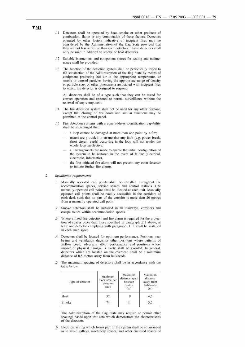
▼M2.11 Detectors shall be operated by heat, smoke or other products of
combustion, flame or any combination of these factors. Detectorsoperated by other factors indicative of incipient fires may beconsidered by the Administration of the flag State provided thatthey are not less sensitive than such detectors. Flame detectors shallonly be used in addition to smoke or heat detectors.
.12 Suitable instructions and component spares for testing and mainte-nance shall be provided.
.13 The function of the detection system shall be periodically tested tothe satisfaction of the Administration of the flag State by means ofequipment producing hot air at the appropriate temperature, orsmoke or aerosol particles having the appropriate range of densityor particle size, or other phenomena associated with incipient firesto which the detector is designed to respond.
All detectors shall be of a type such that they can be tested forcorrect operation and restored to normal surveillance without therenewal of any component.
.14 The fire detection system shall not be used for any other purpose,except that closing of fire doors and similar functions may bepermitted at the control panel.
.15 Fire detection systems with a zone address identification capabilityshall be so arranged that:
— a loop cannot be damaged at more than one point by a fire;— means are provided to ensure that any fault (e.g. power break,
short circuit, earth) occurring in the loop will not render thewhole loop ineffective,
— all arrangements are made to enable the initial configuration ofthe system to be restored in the event of failure (electrical,electronic, informatic),
— the first initiated fire alarm will not prevent any other detectorto initiate further fire alarms.
.2 Installation requirements
.1 Manually operated call points shall be installed throughout theaccommodation spaces, service spaces and control stations. Onemanually operated call point shall be located at each exit. Manuallyoperated call points shall be readily accessible in the corridors ofeach deck such that no part of the corridor is more than 20 metresfrom a manually operated call point.
.2 Smoke detectors shall be installed in all stairways, corridors andescape routes within accommodation spaces.
.3 Where a fixed fire detection and fire alarm is required for the protec-tion of spaces other than those specified in paragraph .2.2 above, atleast one detector complying with paragraph .1.11 shall be installedin each such space.
.4 Detectors shall be located for optimum performance. Positions nearbeams and ventilation ducts or other positions where patterns ofairflow could adversely affect performance and positions whereimpact or physical damage is likely shall be avoided. In general,detectors which are located on the overhead shall be a minimumdistance of 0,5 metres away from bulkheads.
.5 The maximum spacing of detectors shall be in accordance with thetable below:
Type of detector
Maximumfloor area per
detector(m2)
Maximumdistance apart
betweencentres(m)
Maximumdistance
away frombulkheads
(m)
Heat 37 9 4,5
Smoke 74 11 5,5
The Administration of the flag State may require or permit otherspacings based upon test data which demonstrate the characteristicsof the detectors.
.6 Electrical wiring which forms part of the system shall be so arrangedas to avoid galleys, machinery spaces, and other enclosed spaces of
1998L0018 — EN — 17.05.2003 — 003.001 — 79

▼M2high fire risk except where it is necessary to provide for fire detec-tion or fire alarm in such spaces or to connect to the appropriatepower supply.
.3 Design requirements
.1 The system and equipment shall be suitably designed to withstandsupply voltage variation and transients, ambient temperaturechanges, vibration, humidity, shock, impact and corrosion normallyencountered in ships.
.2 Smoke detectors to be installed in stairways, corridors and escaperoutes within accommodation spaces as required by paragraph .2.2shall be certified to operate before the smoke density exceeds12,5 % obscuration per metre, but not until the smoke densityexceeds 2 % obscuration per metre.
Smoke detectors to be installed in other spaces shall operate withinsensitivity limits to the satisfaction of the Administration of the flagState having regard to the avoidance of detector insensitivity or over-sensitivity.
.3 Heat detectors shall be certified to operate before the temperatureexceeds 78 ºC but not until the temperature exceeds 54 ºC, whenthe temperature is raised to those limits at a rate less than 1 ºC perminute. At higher rates of temperature rise, the heat detector shalloperate within temperature limits to the satisfaction of the Adminis-tration of the flag State having regard to the avoidance of detectorinsensitivity or oversensitivity.
.4 The permissible temperature of operation of heat detectors may beincreased to 30 ºC above the maximum deckhead temperature indrying rooms and similar spaces of a normal high ambient tempera-ture.
NEW CLASS B, C AND D SHIPS, CONSTRUCTED ON OR AFTER1 JANUARY 2003:
.4.1 The fixed fire detection and fire alarm systems shall be of an approvedtype, complying with the provisions of the Fire Safety Systems Code.
.4.2 Manually operated call points complying with the Fire Safety SystemsCode shall be installed throughout the accommodation spaces, servicespaces and control stations. One manually operated call point shall belocated at each exit. Manually operated call points shall be readily acces-sible in the corridors of each deck such that no part of the corridor ismore than 20 metres from a manually operated call point.
NEW CLASS A, B, C AND D SHIPS:
.5 In addition to the above provisions, the Administration of the flag Stateshall ensure that safety provisions on the installations regarding theirindependence from other installations or systems, the corrosion resistanceof their components, the electrical power supply to their control system,and the availability of instructions for their operation and maintenanceshall be complied with.
10 Arrangements for oil fuel, lubricating oil and other flammable oils (R15)
NEW CLASS B, C AND D AND EXISTING CLASS B SHIPS:
.1 Limitations in the use of oil as fuel
The following limitations shall apply to the use of oil as fuel:
.1 Except as otherwise permitted by this paragraph, no oil fuel with aflashpoint of less than 60 ºC shall be used.
.2 In emergency generators, oil fuel with a flashpoint of not less than43 ºC may be used.
.3 Subject to such additional precautions as it may consider necessaryand on condition that the ambient temperature of the space in whichsuch oil fuel is stored or used shall not be allowed to rise to within10 ºC below the flashpoint of the oil fuel, the Administration of theflag State may permit the general use of oil fuel having a flashpointof less than 60 ºC but not less than 43 ºC.
1998L0018 — EN — 17.05.2003 — 003.001 — 80

▼M2For ships constructed on or after 1 January 2003 oil fuel having aflashpoint of less than 60 ºC but not less than 43 ºC may bepermitted subject to the following:
.3.1 fuel oil tanks except those arranged in double bottom compart-ments shall be located outside of machinery spaces of categoryA;
.3.2 provisions for the measurement of oil temperature are providedon the suction pipe of the fuel pump;
.3.3 stop valves and/or cocks are provided on the inlet side andoutlet side of the oil fuel strainers and;
.3.4 pipe joints of welded construction or of circular cone type orspherical type union joint are applied as much as possible.
The flashpoint of oils shall be determined by an approved closed cupmethod.
.2 Oil fuel arrangements
In a ship in which oil fuel is used, the arrangements for the storage,distribution and utilisation of the oil fuel shall be such as to ensure thesafety of the ship and persons on board and shall at least comply with thefollowing provisions:
.1.1 As far as practicable, parts of the oil fuel system containing heatedoil under pressure exceeding 0,18 N/mm2 shall not be placed in aconcealed position such that defects and leakage cannot readily beobserved. The machinery spaces in way of such parts of the oilfuel system shall be adequately illuminated.
.1.2 By heated oil is meant oil the temperature of which after heating ishigher than 60 ºC or higher than the current flashpoint of the oil, ifthis is lower than 60 ºC.
.2 The ventilation of machinery spaces shall be sufficient under allnormal conditions to prevent accumulation of oil vapour.
.3 As far as practicable, oil fuel tanks shall be part of the ship's struc-ture and shall be located outside machinery spaces. Where oil fueltanks, other than double bottom tanks, are necessarily located adja-cent to or within machinery spaces, at least one of their verticalsides shall be contiguous to the machinery space boundaries, andshall preferably have a common boundary with the double bottomtanks, and the area of the tank boundary common with themachinery spaces shall be kept to a minimum. Where such tanksare situated within the boundaries of machinery spaces they shallnot contain oil fuel having a flashpoint of less than 60 ºC. The useof freestanding oil fuel tanks shall be avoided and shall be prohibitedin machinery spaces.
.4 No oil fuel tank shall be situated where spillage or leakage therefromcan constitute a hazard by falling on heated surfaces. Precautionsshall be taken to prevent any oil that may escape under pressurefrom any pump, filter or heater from coming into contact with heatedsurfaces.
.5 Every oil fuel pipe, which, if damaged, would allow oil to escapefrom a storage, settling or daily service tank, having a capacity of500 litres or above, situated above the double bottom, shall be fittedwith a cock or valve directly on the tank capable of being closedfrom a safe position outside the space concerned in the event of afire occurring in the space in which such tanks are situated. In thespecial case of deep tanks situated in any shaft or pipe tunnel orsimilar space, valves on the tank shall be fitted but control in theevent of fire may be effected by means of an additional valve onthe pipe or pipes outside the tunnel or similar space. If such addi-tional valve is fitted in the machinery space it shall be operatedfrom a position outside this space.
In ships constructed on or after 1 January 2003 the controls forremote operation of the valve for the emergency generator fuel tankshall be in a separate location from the controls for remote operationof other valves located in machinery spaces.
.6 Safe and efficient means of ascertaining the amount of oil fuelcontained in any oil fuel tank shall be provided.
1998L0018 — EN — 17.05.2003 — 003.001 — 81

▼M2NEW CLASS B, C AND D SHIPS:
.1 Sounding pipes shall not terminate in any space where the riskof ignition of spillage from the sounding pipe might arise. Inparticular, they shall not terminate in passenger or crewspaces. As a general rule, sounding pipes shall not terminatein machinery spaces. However, where the Administration ofthe flag State considers that these latter requirements areimpracticable, it may permit termination of sounding pipes inmachinery spaces on condition that all the following require-ments are met:
.1.1 in addition, an oil-level gauge is provided meeting the require-ments of subparagraph .2.6.2;
.1.2 the sounding pipes terminate in locations remote from ignitionhazards unless precautions are taken, such as the fitting ofeffective screens, to prevent the oil fuel in the case of spillagethrough the terminations of the sounding pipes from cominginto contact with a source of ignition;
.1.3 the termination of sounding pipes are fitted with self-closingblanking devices and with a small-diameter self-closingcontrol cock located below the blanking device for the purposeof ascertaining before the blanking device is opened that oilfuel is not present. Provision shall be made as to ensure thatany spillage of oil fuel through the control cock involves noignition hazard.
NEW CLASS B, C AND D AND EXISTING CLASS B SHIPS:
.2 Other means of ascertaining the amount of oil fuel containedin any oil fuel tank may be permitted if such means, like themeans provided in subparagraph .2.6.1.1, do not require pene-tration below the top of the tank, and providing their failure oroverfilling of the tanks will not permit release of fuel.
.3 Means prescribed in subparagraph .2.6.2 shall be maintainedin the proper condition to ensure their continued accuratefunctioning in service.
.7 Provision shall be made to prevent overpressure in any oil tank or inany part of the oil fuel system, including the filling pipes served bypumps on board. Any relief valves and air or overflow pipes shalldischarge to a position where there is no risk of fire or explosionfrom the emergence of oils and vapour and shall not lead into crewspaces, passenger spaces nor into special category spaces, closed ro-ro spaces, machinery spaces or similar spaces, situated in ships,constructed on or after 1 January 2003.
.8 Oil fuel pipes and their valves and fittings shall be of steel or otherapproved material, except that restricted use of flexible pipes may bepermitted. Such flexible pipes and end attachments shall be ofapproved fire-resisting materials of adequate strength.
For valves, fitted to oil fuel tanks and which are under static pres-sure, steel or spheroidal-graphite cast iron may be accepted.However, ordinary cast iron valves may be used in piping systems,where the design pressure is lower than 7 bar and the designtemperature is below 60 ºC.
NEW CLASS B, C AND D SHIPS:
.9 All external high pressure fuel delivery lines between the highpressure fuel pumps and fuel injectors shall be protected with ajacketed piping system capable of containing fuel from a highpressure line failure. A jacketed pipe incorporates an outer pipeinto which the high-pressure fuel pipe is placed forming a perma-nent assembly. The jacketed piping system shall include a meansfor collection of leakages and arrangements shall be provided foran alarm to be given of a fuel line failure.
.10 All surfaces with temperatures above 220 ºC which may beimpinged as a result of a fuel system failure shall be properly insu-lated.
.11 Oil fuel lines shall be screened or otherwise suitably protected toavoid as far as practicable oil spray or oil leakages onto hotsurfaces, into machinery air intakes, or other sources of ignition.The number of joints in such piping systems shall be kept to aminimum.
1998L0018 — EN — 17.05.2003 — 003.001 — 82

▼M2NEW CLASS B, C AND D SHIPS, CONSTRUCTED ON OR AFTER1 JANUARY 2003:
.12 Oil fuel lines shall not be located immediately above or near unitsof high temperature including boilers, steam pipelines, exhaustmanifolds, silencers or other equipment required to be insulated.As far as practicable, oil fuel lines shall be arranged far apartfrom hot surfaces, electrical installations or other sources of igni-tion and shall be screened or otherwise suitably protected to avoidoil spray or oil leakage onto the sources of ignition. The number ofjoints in such piping systems shall be kept to a minimum.
.13 Components of a diesel engine fuel system shall be designedconsidering the maximum peak pressure which will be experiencedin service, including any high pressure pulses which are generatedand transmitted back into fuel supply and spill lines by the actionof fuel injection pumps. Connections within the fuel supply andspill lines shall be constructed having regard to their ability toprevent pressurised oil fuel leaks while in service and after main-tenance.
.14 In multi-engine installations which are supplied from the same fuelsource, means of isolating the fuel supply and spill piping to indi-vidual engines, shall be provided. The means of isolation shall notaffect the operation of the other engines and shall be operable froma position not rendered inaccessible by a fire on any of the engines
.15 Where the Administration of the flag State may permit theconveying of oil and combustible liquids through accommodationand service spaces, the pipes conveying oil or combustible liquidsshall be of a material approved by the Administration havingregarded of the fire risk.
.16 Existing class B ships shall comply with the requirements ofparagraphs .2.9 to .2.11 not later than 1 July 2003, except that asuitable enclosure of engines having an output of 375 kW or lesshaving fuel injection pumps serving more than one injector may beused as an alternative to the jacketed piping system inparagraph .2.9.
NEW CLASS B, C AND D AND EXISTING CLASS B SHIPS:
.3 Lubricating oil arrangements
The arrangements for the storage, distribution and utilisation of oil usedin pressure lubrication systems shall be such as to ensure the safety ofthe ship and persons on board, and such arrangements in machineryspaces shall at least comply with the provisions of paragraphs .2.1, .2.4,.2.5, .2.6, .2.7, .2.8, .2.10 and .2.11, except that:
.1 this does not preclude the use of sight-flow glasses in lubricatingsystems provided that they are shown by test to have a suitabledegree of fire resistance. If sight-flow glasses are used, the pipe shallbe provided with valves in both ends. The valve at the lower end ofthe pipe shall be of a self-closing type;
.2 sounding pipes may be authorised in machinery spaces; the require-ments of paragraphs .2.6.1.1 and .2.6.1.3 need not be applied oncondition that the sounding pipes are fitted with appropriate meansof closure.
For ships constructed on or after 1 January 2003 the provisions ofparagraph 10.2.5 shall also apply to lubricating oil tanks except thoseof having a capacity less than 500 litres, storage tanks on whichvalves are closed during the normal operation of the ship or whereit is determined that the unintended operation of a quick closingvalve on the lubricating oil tank would endanger the safe operationof the main propulsion and essential auxiliary machinery.
.4 Arrangements for other flammable oils
The arrangements for the storage, distribution and utilisation of otherflammable oils employed under pressure in power transmission systems,control and activating systems and heating systems shall be such as toensure the safety of the ship and persons on board. In locations wheremeans of ignition are present, such arrangements shall at least complywith the provisions of paragraphs .2.4, .2.6, .2.10 and .2.11 and with theprovisions of paragraphs .2.7 and .2.8 in respect of strength and construc-tion.
1998L0018 — EN — 17.05.2003 — 003.001 — 83
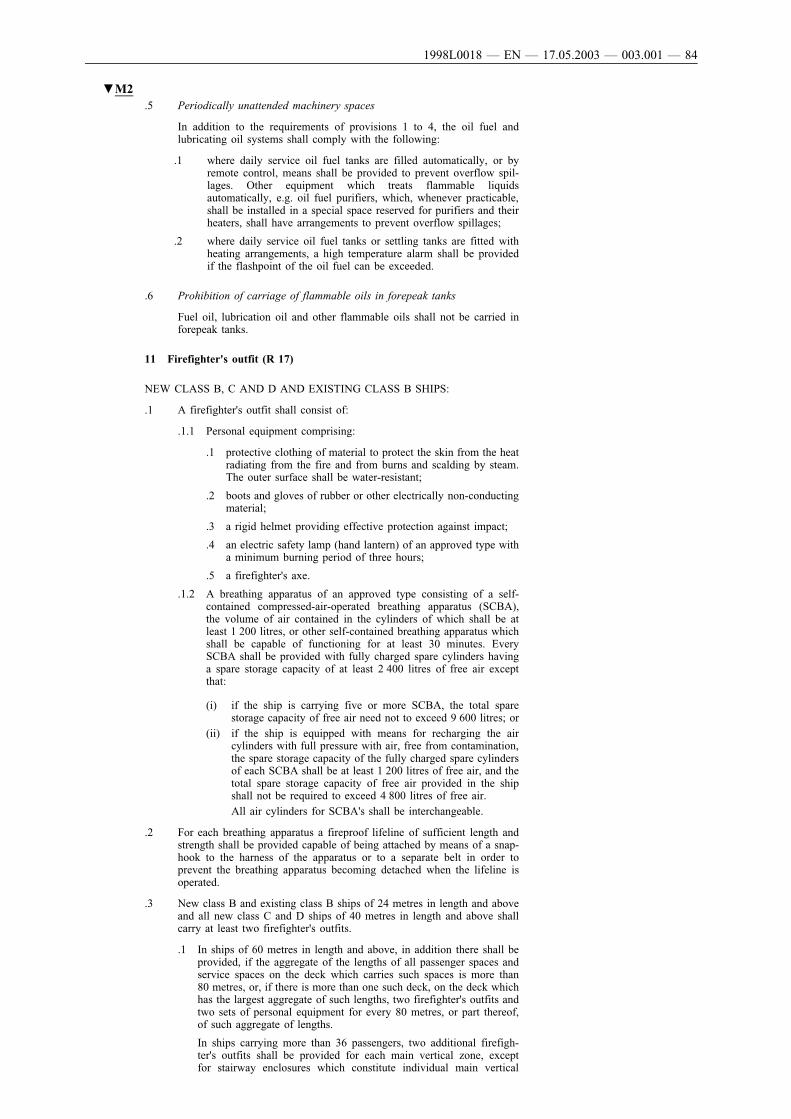
▼M2.5 Periodically unattended machinery spaces
In addition to the requirements of provisions 1 to 4, the oil fuel andlubricating oil systems shall comply with the following:
.1 where daily service oil fuel tanks are filled automatically, or byremote control, means shall be provided to prevent overflow spil-lages. Other equipment which treats flammable liquidsautomatically, e.g. oil fuel purifiers, which, whenever practicable,shall be installed in a special space reserved for purifiers and theirheaters, shall have arrangements to prevent overflow spillages;
.2 where daily service oil fuel tanks or settling tanks are fitted withheating arrangements, a high temperature alarm shall be providedif the flashpoint of the oil fuel can be exceeded.
.6 Prohibition of carriage of flammable oils in forepeak tanks
Fuel oil, lubrication oil and other flammable oils shall not be carried inforepeak tanks.
11 Firefighter's outfit (R 17)
NEW CLASS B, C AND D AND EXISTING CLASS B SHIPS:
.1 A firefighter's outfit shall consist of:
.1.1 Personal equipment comprising:
.1 protective clothing of material to protect the skin from the heatradiating from the fire and from burns and scalding by steam.The outer surface shall be water-resistant;
.2 boots and gloves of rubber or other electrically non-conductingmaterial;
.3 a rigid helmet providing effective protection against impact;
.4 an electric safety lamp (hand lantern) of an approved type witha minimum burning period of three hours;
.5 a firefighter's axe.
.1.2 A breathing apparatus of an approved type consisting of a self-contained compressed-air-operated breathing apparatus (SCBA),the volume of air contained in the cylinders of which shall be atleast 1 200 litres, or other self-contained breathing apparatus whichshall be capable of functioning for at least 30 minutes. EverySCBA shall be provided with fully charged spare cylinders havinga spare storage capacity of at least 2 400 litres of free air exceptthat:
(i) if the ship is carrying five or more SCBA, the total sparestorage capacity of free air need not to exceed 9 600 litres; or
(ii) if the ship is equipped with means for recharging the aircylinders with full pressure with air, free from contamination,the spare storage capacity of the fully charged spare cylindersof each SCBA shall be at least 1 200 litres of free air, and thetotal spare storage capacity of free air provided in the shipshall not be required to exceed 4 800 litres of free air.
All air cylinders for SCBA's shall be interchangeable.
.2 For each breathing apparatus a fireproof lifeline of sufficient length andstrength shall be provided capable of being attached by means of a snap-hook to the harness of the apparatus or to a separate belt in order toprevent the breathing apparatus becoming detached when the lifeline isoperated.
.3 New class B and existing class B ships of 24 metres in length and aboveand all new class C and D ships of 40 metres in length and above shallcarry at least two firefighter's outfits.
.1 In ships of 60 metres in length and above, in addition there shall beprovided, if the aggregate of the lengths of all passenger spaces andservice spaces on the deck which carries such spaces is more than80 metres, or, if there is more than one such deck, on the deck whichhas the largest aggregate of such lengths, two firefighter's outfits andtwo sets of personal equipment for every 80 metres, or part thereof,of such aggregate of lengths.
In ships carrying more than 36 passengers, two additional firefigh-ter's outfits shall be provided for each main vertical zone, exceptfor stairway enclosures which constitute individual main vertical
1998L0018 — EN — 17.05.2003 — 003.001 — 84

▼M2zones and for main vertical zones of limited length in the fore andaft end of a ship which do not include, machinery spaces or maingalleys.
.2 In ships of 40 metres in length and above but less than 60 metrestwo firefighter's outfits have to be provided.
.3 In new class B and existing class B ships of 24 metres in length andabove but less than 40 metres, also two firefighter's outfits have tobe provided, but with only one spare aircharge for self-containedbreathing apparatus.
.4 In new and existing class B ships of less than 24 metres length and innew class C and D ships of less than 40 metres in length no firefighter'soutfit has to be provided.
.5 The firefighter's outfits or sets of personal equipment shall be so storedas to be easily accessible and ready for use and, where more than onefire-fighter's outfit or more than one set of personal equipment is carried,they shall be stored in widely separated positions. At least one firefigh-ter's outfit and one set of personal equipment shall be available at anyone such position.
12 Miscellaneous items (R 18)
NEW CLASS B, C AND D AND EXISTING CLASS B SHIPS:
.1 Where class ‘A’ divisions are penetrated for the passage of electriccables, pipes, trunks, ducts etc., or for girders, beams or other structuralmembers, arrangements shall be made to ensure that the fire resistance isnot impaired in so far as is reasonable and practicable.
For ships, which are constructed on or after 1 January 2003, where‘A’ class divisions are penetrated, such penetrations shall be tested inaccordance with the Fire Test Procedures Code, to ensure that the fireresistance of the divisions is not impaired.
In the case of ventilation ducts regulations II-2/B/9.2.2b and II-2/B/9.3apply.
However, where a pipe penetration is made of steel or equivalent mate-rial having a thickness of 3 mm or greater and a length of not less than900 mm (preferably 450 mm on each side of the division) and no open-ings, testing is not required.
Such penetrations shall be suitably insulated by extension of the insula-tion at the same level of the division.
.2 Where class ‘B’ divisions are penetrated for the passage of electriccables, pipes, trunks, ducts etc., or for the fitting of ventilation terminals,lighting fixtures and similar devises, arrangements shall be made toensure that the fire resistance is not impaired in so far as is reasonableand practicable. In ships, which are constructed on or after 1 January2003 for such penetrations arrangements shall be made to ensure thatthe fire resistance of the divisions is not impaired.
Pipes other than steel or copper that penetrate ‘B’ class divisions shall beprotected by either:
.1 a fire tested penetration device, suitable for the fire resistance of thedivision pierced and the type of the pipe used; or
.2 a steel sleeve, having a thickness of not less than 1,8 mm and alength of not less than 900 mm for pipe diameters of 150 mm ormore and not less than 600 mm for pipe diameters of less than150 mm ( preferably equally divided to each side of the division).
The pipe shall be connected to the ends of the sleeve by flanges orcouplings or the clearance between the sleeve and the pipe shall notexceed 2,5 mm or any clearance between pipe and sleeve shall bemade tight by means of non-combustible or other suitable material.
.3 Pipes penetrating ‘A’ or ‘B’ class divisions shall be of approved mate-rials having regard to the temperature such divisions are required towithstand.
In ships, constructed on or after 1 January 2003, no-insulated metallicpipes penetrating ‘A’ or ‘B’ class divisions shall be of materials havinga melting temperature which exceeds 950 ºC for ‘A-0’ and 850 ºC for‘B-0’ class divisions.
1998L0018 — EN — 17.05.2003 — 003.001 — 85

▼M2.4 In accommodation spaces, service spaces or control stations, pipes
intended to convey oil or other flammable liquids shall be of a suitablematerial and construction having regard to the fire risk.
.5 Materials readily rendered ineffective by heat shall not be used for overboard scuppers, sanitary discharges, and other outlets which are close tothe waterline and where the failure of the material in the event of firewould give rise to danger of flooding.
.6 Electric radiators, if used, shall be fixed in position and so constructed asto reduce fire risks to a minimum. No such radiators shall be fitted withan element so exposed that clothing, curtains, or other similar materialscan be scorched or set on fire by heat from the element.
.7 All waste receptacles shall be constructed of non-combustible materialswith no openings in the sides or bottom.
.8 In spaces where penetration of oil products is possible, the surface ofinsulation shall be impervious to oil or oil vapours.
NEW CLASS A, B, C AND D SHIPS: In spaces in which there is a riskof oils splashing or oil vapour, e.g. in machinery spaces of category A,the surface of the insulating material shall be impermeable by oil and oilvapour. Where there is covering by non-perforated steel plate or othernon-combustible materials (not aluminium) which is the ultimatephysical surface, this covering may be joined by seaming, riveting, etc.
.9 Paint lockers and flammable liquid lockers shall be protected by anapproved fire-extinguishing arrangement, enabling the crew to extinguisha fire without entering the space.
In ships, which are constructed on or after 1 January 2003:
.1 Paint lockers shall be protected by:
.1.1 a carbon dioxide system, designed to give a minimum volumeof free gas equal to 40 % of the gross volume of the protectedspace;
.1.2 a dry powder system, designed for at least 0,5 kg powder/m3;
.1.3 a waterspraying or sprinkler system, designed for 5 litres/m2
min. Water spraying systems may be connected to the firemain of the ship; or
.1.4 a system providing equivalent protection, as determined by theAdministration of the flag State.
In any case the system shall be operable from outside theprotected space.
.2 Flammable liquid lockers shall be protected by an appropriate fireextinguishing arrangement approved by the Administration of theflag State.
.3 For lockers of a deck area of less than 4 m2, which do not giveaccess to accommodation spaces, a carbon dioxide portable extin-guisher sized to provide a minimum volume of free gas equal to40 % of the gross volume of the space may be accepted in lieu of afixed system.
A discharge port shall be arranged in the locker to allow thedischarge of the extinguisher without having to enter into theprotected space. The required portable fire extinguisher shall bestowed adjacent to the port. Alternatively a port or hose connectionmay be provided to facilitate the use of fire main water.
NEW CLASS A, B, C AND D SHIPS AND EXISTING CLASS B SHIPS:
.10 Deep-fat friers, boiling and roasting apparatus:
When deep-fat friers, boiling and roasting apparatus are installed andused in spaces outside the main galley, the Administration of the flagState shall impose additional safety measures with regard to the specificfire hazards associated with the use of this type of equipment.
In ships, which are constructed on or after 1 January 2003, deep-fatcooking equipment shall be fitted with the following:
.1 an automatic or manual extinguishing system tested to an interna-tional standard in accordance with Publication ISO 15371:2000 onfire-extinguishing systems for protection of galley deep-fat cookingequipment;
.2 a primary and backup thermostat with an alarm to alert the operatorin the event of failure of either thermostat;
1998L0018 — EN — 17.05.2003 — 003.001 — 86

▼M2.3 arrangements for automatically shutting off the electrical power upon
activation of the extinguishing system;
.4 an alarm for indicating operation of the extinguishing system in thegalley where the equipment is installed; and
.5 controls for manual operation of the extinguishing system, which areclearly labelled for ready use of the crew.
In ships, which are constructed before 1 January 2003, new installationsfor deep-fat cooking equipment shall comply with the requirements ofthis paragraph.
NEW CLASS A, B, C AND D SHIPS:
.11 Heat bridges:
In the implementation of fire proofing measures, steps shall be under-taken by the Administration of the flag State to prevent heat transferthrough heat bridges, e.g. between decks and bulkheads.
In ships, which are constructed on or after 1 January 2003, the insulationof a deck or bulkhead shall be carried past the penetration, intersection orterminal point for a distance of at least 450 mm in the case of steel andaluminium structures. If a space is divided with a deck or a bulkhead of‘A’ class standard having insulation of different values, the insulationwith the higher value shall continue on the deck or bulkhead with theinsulation of the lesser value for a distance of at least 450 mm.
NEW CLASS A, B, C AND D SHIPS AND EXISTING CLASS B SHIPS:
.12 Pressurised gas containers:
All portable containers for gases which are compressed, liquefied orbroken down under pressure, which may feed a possible fire, shall imme-diately after use be put in a suitable place above the bulkhead deck, fromwhich there is direct access to open deck.
13 Fire control plans (R 20)
NEW CLASS B, C AND D AND EXISTING CLASS B SHIPS:
.1 In all ships general arrangement plans shall be permanently exhibited forthe guidance of the ship's officers, showing clearly for each deck thecontrol stations, the various fire sections enclosed by ‘A’ class divisions,the sections enclosed by ‘B’ class divisions together with particulars ofthe fire detection and fire alarm systems, the sprinkler installation, thefire-extinguishing appliances, means of access to different compartments,decks, etc. and the ventilating system including particulars of the fancontrol positions, the position of dampers and identification numbers ofthe ventilating fans serving each section. Alternatively the aforemen-tioned details may be set out in a booklet, a copy of which shall besupplied to each officer, and one copy shall at all times be available onboard in an accessible position. Plans and booklets shall be kept up todate, any alterations being recorded thereon as soon as practicable.Description in such plans and booklets shall be in the official languageof the flag State. If the language is neither English nor French, a transla-tion into one of these languages shall be included. In the case the ship isengaged on domestic voyages in another Member State, a translation intothe official language of that host State, if this language is neither Englishnor French, shall be included.
For new class B, C and D ships, constructed on or after 1 January 2003the information to be provided with the required fire control plans andbooklets and the graphical symbols to be used for the fire control plansshall be in accordance with the IMO Resolutions A.756 (18) andA.654 (16).
.2 In all ships with a length of 24 metres and over a duplicate set of firecontrol plans or a booklet containing such plans shall be permanentlystored in a prominently marked weather tight enclosure outside the deck-house for the assistance of shore side fire-fighting personnel.
1998L0018 — EN — 17.05.2003 — 003.001 — 87

▼M214 Operational readiness and maintenance
NEW CLASS B, C AND D AND EXISTING CLASS B SHIPS:
.1 General requirements
At all times while the ship is in service, the fire protection systems andfire-fighting systems and appliances shall be maintained ready for use.
A ship is not in service when:
.1 it is in for repairs or lay-up (either at anchor or at port ) or in dry-dock;
.2 it is declared not in service by the owner or the owner's representa-tive; and
.3 if there are no passengers on board.
The following fire protection systems shall be kept in good order so as toensure their required performance if a fire occurs:
.1.1 Operational readiness
.1 structural fire protection including fire resisting divisions andprotection of openings and penetrations in these divisions;
.2 fire detection and fire alarm systems; and
.3 means of escape systems and appliances.
Fire-fighting systems and appliances shall be kept in good workingorder and readily available for immediate use. Portable extin-guishers which have been discharged shall be immediatelyrecharged or replaced with an equivalent unit.
.1.2 Maintenance, testing and inspections
Maintenance, testing and inspections shall be carried out based onthe guidelines developed by IMO and in a manner having dueregard to ensuring the reliability of fire-fighting systems and appli-ances.
A maintenance plan shall be kept on board the ship and shall beavailable for inspection, whenever required by the Administrationof the flag State.
The maintenance plan shall include at least the following fireprotection systems and fire-fighting systems and appliances, whereinstalled:
.1 fire mains, fire pumps and hydrants including hoses andnozzles;
.2 fixed fire detection and fire alarm systems;
.3 fixed fire-extinguishing systems and other fire-extinguishingappliances;
.4 automatic sprinkler, fire detection and fire alarm systems;
.5 ventilation systems including fire and smoke dampers, fansand their controls;
.6 emergency shut down of fuel supply;
.7 fire doors including their controls;
.8 general emergency alarm systems;
.9 emergency escape breathing devices;
.10 portable fire extinguishers including spare charges; and
.11 firefighter's outfits.
The maintenance programme may be computer-based.
.2 Additional requirements
For new class B, C and D ships, constructed on or after 1 January 2003,carrying more than 36 passengers a maintenance plan for low-locationlighting and public address systems shall be developed in addition tothe maintenance plan mentioned under paragraph .1.2.
1998L0018 — EN — 17.05.2003 — 003.001 — 88

▼M215 Instructions, on-board training and drills
NEW CLASS B, C AND D AND EXISTING SHIPS:
.1 Instructions, duties and organisation
.1 Crew members shall receive instructions on fire safety on-board theship.
.2 Crew members shall receive instructions on their assigned duties.
.3 Parties responsible for fire extinguishing shall be organised. Theseparties shall have the capability to complete their duties at all timeswhile the ship is in service.
.2 On-board training and drills
.1 Crew members shall be trained to be familiar with the arrangementsof the ship as well as the location and operation of any fire-fightingsystems and appliances that they may be called upon to use.
.2 Training in the use of the emergency escape breathing devices shallbe considered as a part of on-board training.
.3 Performance of crew members assigned fire-fighting duties shall beperiodically evaluated by conducting on-board training and drills toidentify areas in need of improvement, to ensure competency infire-fighting skills is maintained and to ensure the operational readi-ness of the fire-fighting organisation.
.4 On-board training in the use of the ship's fire-extinguishing systemsand appliances shall be planned and conducted in accordance withprovisions of regulation III/19.4.1 of SOLAS 1974, as amended.
.5 Fire drills shall be conducted and recorded in accordance with theprovisions of regulations III/19.3.4, III/19.5 and III/30 of SOLAS1974, as amended.
.3 Training manuals
A training manual shall be provided in each crew mess room and recrea-tion room or in each crew cabin. The training manual shall be written inthe working language of the ship. The training manual, which maycomprise several volumes, shall contain the instructions and the informa-tion required in this paragraph in easily understood terms and illustratedwherever possible. Any part of such information may be provided in theform of audio-visual aides in lieu of the manual. The training manualshall explain the following in detail:
.1 general fire safety practice and precautions related to the dangers ofsmoking, electrical hazards, flammable liquids and similar commonshipboard hazards;
.2 general instructions on fire-fighting activities and fire-fighting proce-dures including procedures for notification of a fire and use ofmanually operated call points;
.3 meanings of ship's alarms;
.4 operation and use of fire-fighting systems and appliances;
.5 operation and use of fire doors;
.6 operation and use of fire and smoke dampers; and
.7 escape systems and appliances.
.4 Fire control plans
Fire control plans have to comply with the requirements of regulation II-2/A-13.
16. Operations
NEW CLASS B, C, D AND EXISTING CLASS B SHIPS:
.1 To provide information and instruction for proper ship and cargo hand-ling operations in relation to fire safety, operational booklets shall beprovided on board.
.2 The required fire operational booklet shall contain the necessary informa-tion and instructions for the safe operation of the ship and cargo handling
1998L0018 — EN — 17.05.2003 — 003.001 — 89

▼M2operations in relation to fire safety. The booklet shall include informationconcerning the crew's responsibilities for the general fire safety of theship while loading and discharging cargo and while underway. For shipscarrying dangerous goods the fire safety booklet shall provide referenceto the pertinent fire-fighting and emergency cargo handling instructionscontained in the International Maritime Dangerous Goods Code.
.3 The fire safety operational booklet shall be written in the workinglanguage of the ship.
.4 The fire safety operational booklet may be combined with the trainingmanuals required in regulation II-2/A/15.3.
PART B
FIRE SAFETY MEASURES
1 Structure (R 23)
NEW CLASS B, C AND D AND EXISTING CLASS B SHIPS:
.1 The hull, superstructures, structural bulkheads, decks and deckhousesshall be constructed of steel or other equivalent material. For the purposeof applying the definition of steel or other equivalent material as given inregulation II-2/A/2.7, the ‘applicable fire exposure’ shall be according tothe integrity and insulation standards given in the tables of regulations 4and 5. For example, where divisions such as decks or sides and ends ofdeckhouses are permitted to have ‘B-0’ fire integrity, the ‘applicable fireexposure’ shall be half an hour.
.2 However, in cases where any part of the structure is of aluminium alloy,the following shall apply:
.1 The insulation of aluminium alloy components of ‘A’ or ‘B’ classdivisions, except structure which is non-load-bearing, shall be suchthat the temperature of the structural core does not rise more than200 ºC above the ambient temperature at any time during the applic-able fire exposure to the standard fire test.
.2 Special attention shall be given to the insulation of aluminium alloycomponents of columns, stanchions and other structural membersrequired to support lifeboat and life-raft stowage, launching andembarkation areas, and ‘A’ and ‘B’ class divisions to ensure:
.1 that for such members supporting lifeboat and life-raft areas and‘A’ class divisions, the temperature rise limitation specified inparagraph .2.1 shall apply at the end of one hour; and
.2 that for such members required to support ‘B’ class divisions,the temperature rise limitation specified in paragraph .2.1 shallapply at the end of half an hour.
.3 Crowns and casings of machinery spaces shall be of steel construc-tion adequately insulated and openings therein, if any, shall besuitably arranged and protected to prevent the spread of fire.
2 Main vertical zones and horizontal zones (R 24)
NEW CLASS B, C AND D SHIPS:
.1.1 In ships carrying more than 36 passengers, the hull, superstructure anddeckhouses shall be subdivided into main vertical zones by A-60 classdivisions.
Steps and recesses shall be kept to a minimum but where they are neces-sary, they shall also be A-60 class divisions.
Where an open deck space, a sanitary or similar space or a tankincluding a fuel oil tank, void space or auxiliary machinery space havinglittle or no fire risk, is on one side or where fuel oil tanks are on bothsides of the division the standard may be reduced to A-0.
NEW CLASS B, C AND D AND EXISTING CLASS B SHIPS:
.1.2 For new class B, C and D ships carrying not more than 36 passengersand for existing class B ships carrying more than 36 passengers, thehull, superstructure and deckhouses in way of accommodation andservice spaces shall be subdivided into main vertical zones by ‘A’ class
1998L0018 — EN — 17.05.2003 — 003.001 — 90

▼M2divisions. These divisions shall have insulation values in accordance withthe tables in regulation 5.
NEW CLASS B, C AND D SHIPS:
.2 As far as practicable, the bulkheads forming the boundaries of the mainvertical zones above the bulkhead deck shall be in line with watertightsubdivision bulkheads situated immediately below the bulkhead deck.The length and width of main vertical zones may be extended to amaximum of 48 metres in order to bring the ends of main vertical zonesto coincide with subdivision watertight bulkheads or in order to accom-modate a large public space extending for the whole length of the mainvertical zone provided that the total area of the main vertical zone is notgreater than 1 600 m2 on any deck. The length or width of a mainvertical zone is the maximum distance between the furthermost pointsof the bulkheads bounding it.
NEW CLASS B, C AND D SHIPS AND EXISTING CLASS B SHIPSCARRYING MORE THAN 36 PASSENGERS:
.3 Such bulkheads shall extend from deck to deck and to the shell or otherboundaries.
.4 Where a main vertical zone is subdivided by horizontal ‘A’ class divi-sions into horizontal zones for the purpose of providing an appropriatebarrier between sprinkled and non-sprinklered zones of the ship, the divi-sions shall extend between adjacent main vertical zone bulkheads and tothe shell or exterior boundaries of the ship and shall be insulated inaccordance with the fire insulation and integrity values given in table 4.2for new ships carrying more than 36 passengers, respectively table 5.2for new ships carrying not more than 36 passengers and existing class Bships carrying more than 36 passengers.
.5 .1 On ships designed for special purposes, such as automobile or rail-road car ferries where the provision of main vertical zonebulkheads would defeat the purpose for which the ship is intended,equivalent protection shall be obtained by dividing space in hori-zontal zones.
.2 However, in a ship with special category spaces, any such spaceshall comply with the applicable provisions of regulation II-2/B/14and in so far as such compliance would be inconsistent with compli-ance with other requirements of this part, the requirements ofregulation II-2/B/14 shall prevail.
3 Bulkheads within a main vertical zone (R 25)
NEW CLASS B, C AND D SHIPS CARRYING MORE THAN 36 PASSEN-GERS:
.1.1 For new ships carrying more than 36 passengers all bulkheads which arenot required to be ‘A’ class divisions shall be at least ‘B’ class or‘C’ class divisions as prescribed in the tables in regulation 4. All suchdivisions may be faced with combustible materials in accordance withthe provisions of regulation 11.
NEW CLASS B, C AND D SHIPS CARRYING NOT MORE THAN36 PASSENGERS AND EXISTING CLASS B SHIPS CARRYING MORETHAN 36 PASSENGERS:
.1.2 For new ships carrying not more than 36 passengers and existing class Bships carrying more than 36 passengers all bulkheads within accommoda-tion and service spaces which are not required to be ‘A’ class divisionsshall be at least ‘B’ class or ‘C’ class divisions as prescribed in the tablesin regulation 5.
If such divisions may be faced with combustible materials in accordancewith the provisions of regulation 11.
NEW CLASS B, C AND D AND EXISTING CLASS B SHIPS:
.2 In new class B, C and D ships carrying not more than 36 passengers andin existing class B ships carrying more than 36 passengers all corridorbulkheads where not required to be ‘A’ class shall be ‘B’ class divisionswhich shall extend from deck to deck except:
.1 when continuous ‘B’ class ceilings or linings are fitted on both sidesof the bulkhead, the portion of the bulkhead behind the continuousceiling or lining shall be of material which, in thickness and compo-
1998L0018 — EN — 17.05.2003 — 003.001 — 91

▼M2sition, is acceptable in the construction of ‘B’ class divisions butwhich shall be required to meet ‘B’ class integrity standards only inso far as is reasonable and practicable;
.2 in the case of a ship protected by an automatic sprinkler systemcomplying with the provisions of regulation II-2/A/8, the corridorbulkheads of ‘B’ class materials may terminate at a ceiling in thecorridor provided such ceiling is of material which, in thickness andcomposition, is acceptable in the construction of ‘B’ class divisions.
Notwithstanding the requirements of regulations 4 and 5, such bulk-heads and ceilings shall be required to meet ‘B’ class integritystandards only in so far as is reasonable and practicable. All doorsand frames in such bulkheads shall be of non-combustible materialsand shall be so constructed and erected as to provide substantial fireresistance.
.3 All bulkheads required to be ‘B’ class division, except corridor bulkheadsprescribed in paragraph .2, shall extend from deck to deck and to theshell or other boundaries unless the continuous ‘B’ class ceilings orlinings fitted on both sides of the bulkheads are at least of the same fireresistance as the bulkhead, in which case the bulkhead may terminate atthe continuous ceiling or lining.
4 Fire integrity of bulkheads and decks in new ships carrying more than36 passengers (R 26)
NEW CLASS B, C AND D SHIPS:
.1 In addition to complying with the specific provisions for fire integrity ofbulkheads and decks mentioned elsewhere in this part, the minimum fireintegrity of all bulkheads and decks shall be as prescribed in tables 4.1and 4.2.
.2 The following requirements shall govern the application of the tables:
.1 Table 4.1 shall apply to bulkheads not bounding either main verticalzones or bounding horizontal zones.
Table 4.2 shall apply to decks not forming steps in main verticalzones nor bounding horizontal zones.
.2 For determining the appropriate fire integrity standards to be appliedto boundaries between adjacent spaces, such spaces are classifiedaccording to their fire risk as shown in categories (1) to (14). Wherethe contents and use of a space are such that there is a doubt as to itsclassification for the purpose of this regulation, it shall be treated asa space within the relevant category having the most stringentboundary requirements. The title of each category is intended to betypical rather than restrictive. The number in parentheses precedingeach category refers to the applicable column or row in the tables.
(1) Control stations:
— spaces containing emergency sources of power andlighting,
— wheelhouse and chartroom,
— spaces containing the ship's radio equipment,
— fire-extinguishing rooms, fire control rooms and fire-recording stations,
— control room for propulsion machinery when locatedoutside the propulsion machinery space,
— spaces containing centralised fire alarm equipment,
— spaces containing centralised emergency public addresssystem stations and equipment.
(2) Stairways:
— interior stairways, lifts and escalators (other than thosewholly contained within the machinery spaces) forpassengers and crew and enclosures thereto;
— in this connection a stairway which is enclosed at onlyone level shall be regarded as part of the space fromwhich it is not separated by a fire door.
(3) Corridors:
— passenger and crew corridors.
1998L0018 — EN — 17.05.2003 — 003.001 — 92

▼M2(4) Evacuation stations and external escape routes:
— survival craft stowage area,— open deck spaces and enclosed promenades forming life-
boat and life-raft embarkation and lowering stations,— assembly stations, internal and external,— external stairs and open decks used for escape routes,— the ship's side to the waterline in the lightest seagoing
condition, superstructure and deckhouse sides situatedbelow and adjacent to the life-rafts and evacuation slide'sembarkation areas.
(5) Open deck spaces:
— open deck spaces and enclosed promenades clear of life-boat and life-raft embarkation and lowering stations,
— air spaces (the space outside superstructures and deck-houses).
(6) Accommodation spaces of minor fire risk:
— cabins containing furniture and furnishing of restrictedfire risk,
— offices and dispensaries containing furniture and furnish-ings of restricted fire risk,
— public spaces containing furniture and furnishings ofrestricted fire risk and having a deck area of less than50 m2.
(7) Accommodation spaces of moderate fire risk:
— spaces as in category (6) above but containing furnitureand furnishing of other than restricted fire risk,
— public spaces containing furniture and furnishing ofrestricted fire risk and having a deck area of 50 m2 ormore,
— isolated lockers and small storerooms in accommodationspaces having areas less than 4 m2 (in which flammableliquids are not stowed),
— sale shops,— motion picture projection and film stowage rooms,— diet kitchens (containing no open flame),— cleaning gear lockers (in which flammable liquids are not
stowed),— laboratories (in which flammable liquids are not stowed),— pharmacies,— small drying rooms (having a deck area of 4 m2 or less),— specie rooms,— operating rooms.
(8) Accommodation spaces of greater fire risk:
— public spaces containing furniture and furnishing of otherthan restricted fire risk and having a deck area of 50 m2
or more,— barber shops and beauty parlours.
(9) sanitary and similar spaces:
— communal sanitary facilities, shower, baths, water closets,etc.,
— small laundry rooms,— indoor swimming pool area,— isolated pantries containing no cooking appliances in
accommodation spaces,— private sanitary facilities shall be considered a portion of
the space in which they are located.
(10) Tanks, voids and auxiliary machinery spaces having little orno fire risk:
— water tanks forming part of the ship's structure;— voids and cofferdams;— auxiliary machinery spaces which do not contain
machinery having a pressure lubrication system andwhere storage of combustibles is prohibited, such as;
1998L0018 — EN — 17.05.2003 — 003.001 — 93

▼M2— ventilation and air-conditioning rooms; windlass room;
steering gear room; stabiliser equipment room; electricalpropulsion motor room; rooms containing section switch-boards and purely electrical equipment other than oil-filled electrical transformers (above 10 kVA); shaft alleysand pipe tunnels; spaces for pumps and refrigerationmachinery (not handling or using flammable liquids),
— closed trunks serving the spaces listed above,
— other closed trunks such as pipe and cable trunks.
(11) Auxiliary machinery spaces, cargo spaces, cargo and other oiltanks and other similar spaces of moderate fire risk:
— cargo oil tanks,
— cargo holds, trunkways and hatchways,
— refrigerated chambers,
— oil fuel tanks (where installed in a separate space with nomachinery),
— shaft alleys and pipe tunnels allowing storage of combus-tibles,
— auxiliary machinery spaces as in category (10) whichcontain machinery having a pressure lubrication systemor where storage of combustibles is permitted,
— oil fuel filling stations,
— spaces containing oil-filled electrical transformers (above10 kVA),
— spaces containing small internal combustion engines ofpower output up to 110 kW driving generators, sprinkler,drencher or fire pumps, bilge pumps, etc.,
— closed trunks serving the spaces listed above.
(12) Machinery spaces and main galleys:
— main propulsion machinery rooms (other than electricpropulsion motor rooms) and boiler rooms,
— auxiliary machinery spaces other than those incategories (10) and (11) which contain internal combus-tion machinery or other oil burning, heating or pumpingunits,
— main galleys and annexes,
— trunks and casings to the spaces listed above.
(13) Storesrooms, workshops, pantries, etc.:
— main pantries not annexed to galleys,
— main laundry,
— large drying rooms (having a deck area of more than 4m2),
— miscellaneous stores,
— mail and baggage rooms,
— garbage rooms,
— workshops (not part of machinery spaces, galleys, etc.),
— lockers and storerooms having areas greater than 4 m2,other than those spaces that have provisions for thestorage of flammable liquids.
(14) Other spaces in which flammable liquids are stowed:
— paint lockers,
— storerooms containing flammable liquids (including dyes,medicines, etc.),
— laboratories (in which flammable liquids are stowed).
.3 Where a single value is shown for the fire integrity of a boundarybetween two spaces, that value shall apply in all cases.
.4 There are no special requirements for material or integrity of bound-aries where only a dash appears in the tables.
.5 The Administration of the flag State shall determine in respect ofcategory (5) spaces whether the insulation values in table 4.1 shallapply to ends of deckhouses and superstructures, and whether theinsulation values in table 4.2 shall apply to weather decks. In nocase shall the requirements of category (5) of table 4.1 or 4.2 neces-sitate enclosure of spaces which in the opinion of the Administrationof the flag State need not be enclosed.
1998L0018 — EN — 17.05.2003 — 003.001 — 94

▼M2.3 Continuous ‘B’ class ceiling or linings, in association with the relevant
decks or bulkheads, may be accepted as contributing wholly or in part,to the required insulation and integrity of a division.
.4 In approving structural fire protection details the Administration of theflag State shall have regard to the risk of heat transmission at intersec-tions and terminal points of required thermal barriers.
1998L0018 — EN — 17.05.2003 — 003.001 — 95

Tab
le4.1
Bulkheadsnotboundingeithermainverticalzonesorhorizontalzones
Spa
ces
(1)
(2)
(3)
(4)
(5)
(6)
(7)
(8)
(9)
(10)
(11)
(12)
(13)
(14)
Con
trol
statio
ns(1
)B-0
(a)
A-0
A-0
A-0
A-0
A-6
0A-6
0A-6
0A-0
A-0
A-6
0A-6
0A-6
0A-6
0
Stairway
s(2
)A-0
(a)
A-0
A-0
A-0
A-0
A-1
5A-1
5A-0
(c)
A-0
A-1
5A-3
0A-1
5A-3
0
Cor
rido
rs(3
)B-1
5A-6
0A-0
B-1
5B-1
5B-1
5B-1
5A-0
A-1
5A-3
0A-0
A-3
0
Eva
cuatio
nstatio
nsan
dex
tern
ales
cape
rout
es(4
)A-0
A(d)-60
(b)
A(d)-60
(b)
A(d)-60
(b)
A-0
(d)
A-0
A-6
0(b)
A-6
0(b)
A-6
0(b)
A-6
0(b)
Ope
nde
cksp
aces
(5)
—A-0
A-0
A-0
A-0
A-0
A-0
A-0
A-0
A-0
Acc
omm
odatio
nsp
aces
ofm
inor
fire
risk
(6)
B-0
B-0
B-0
CA-0
A-0
A-3
0A-0
A-3
0
Acc
omm
odatio
nsp
aces
ofm
oderate
fire
risk
(7)
B-0
B-0
CA-0
A-1
5A-6
0A-1
5A-6
0
Acc
omm
odatio
nsp
aces
ofgr
eater
fire
risk
(8)
B-0
CA-0
A-3
0A-6
0A-1
5A-6
0
San
itary
and
sim
ilar
spac
es(9
)C
A-0
A-0
A-0
A-0
A-0
Tan
ks,
void
san
dau
xiliary
mac
hine
rysp
aces
havi
nglittle
orno
fire
risk
(10)
A-0
(a)
A-0
A-0
A-0
A-0
Aux
iliary
mac
hine
rysp
aces
,ca
rgo
spac
es,
carg
oan
dot
her
oil
tank
san
dot
her
sim
ilar
spac
esof
mod
erate
fire
risk
(11)
A-0
(a)
A-0
A-0
A-1
5
Mac
hine
rysp
aces
and
main
galley
s(1
2)A-0
(a)
A-0
A-6
0
Sto
rero
oms,
wor
ksho
ps,
pant
ries
,etc.
(13)
A-0
(a)
A-0
Oth
ersp
aces
inwhi
chflam
mab
leliqu
idsare
stow
ed(1
4)A-3
0
▼M2
1998L0018 — EN — 17.05.2003 — 003.001 — 96
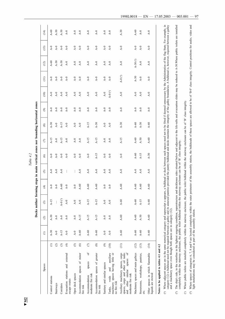
Tab
le4.2
Decksneitherformingstepsinmainverticalzonesnorboundinghorizontalzones
Spa
ces
(1)
(2)
(3)
(4)
(5)
(6)
(7)
(8)
(9)
(10)
(11)
(12)
(13)
(14)
Con
trol
statio
ns(1
)A-3
0A-3
0A-1
5A-0
A-0
A-0
A-1
5A-3
0A-0
A-0
A-0
A-6
0A-0
A-6
0
Stairway
s(2
)A-0
A-0
—A-0
A-0
A-0
A-0
A-0
A-0
A-0
A-0
A-3
0A-0
A-3
0
Cor
rido
rs(3
)A-1
5A-0
A-0
(a)
A-6
0A-0
A-0
A-1
5A-1
5A-0
A-0
A-0
A-3
0A-0
A-3
0
Eva
cuatio
nstatio
nsan
dex
tern
ales
cape
rout
es(4
)A-0
A-0
A-0
A-0
—A-0
A-0
A-0
A-0
A-0
A-0
A-0
A-0
A-0
Ope
nde
cksp
aces
(5)
A-0
A-0
A-0
A-0
—A-0
A-0
A-0
A-0
A-0
A-0
A-0
A-0
A-0
Acc
omm
odatio
nsp
aces
ofm
inor
fire
risk
(6)
A-6
0A-1
5A-0
A-6
0A-0
A-0
A-0
A-0
A-0
A-0
A-0
A-0
A-0
A-0
Acc
omm
odatio
nsp
aces
ofm
oderate
fire
risk
(7)
A-6
0A-1
5A-1
5A-6
0A-0
A-0
A-1
5A-1
5A-0
A-0
A-0
A-0
A-0
A-0
Acc
omm
odatio
nsp
aces
ofgr
eater
fire
risk
(8)
A-6
0A-1
5A-1
5A-6
0A-0
A-1
5A-1
5A-3
0A-0
A-0
A-0
A-0
A-0
A-0
San
itary
and
sim
ilar
spac
es(9
)A-0
A-0
A-0
A-0
A-0
A-0
A-0
A-0
A-0
A-0
A-0
A-0
A-0
A-0
Tan
ks,
void
san
dau
xiliary
mac
hine
rysp
aces
havi
nglittle
orno
fire
risk
(10)
A-0
A-0
A-0
A-0
A-0
A-0
A-0
A-0
A-0
A-0
(a)
A-0
A-0
A-0
A-0
Aux
iliary
mac
hine
rysp
aces
,ca
rgo
spac
es,
carg
oan
dot
her
oil
tank
san
dot
her
sim
ilar
spac
esof
mod
erate
fire
risk
(11)
A-6
0A-6
0A-6
0A-6
0A-0
A-0
A-1
5A-3
0A-0
A-0
A-0
(a)
A-0
A-0
A-3
0
Mac
hine
rysp
aces
and
main
galley
s(1
2)A-6
0A-6
0A-6
0A-6
0A-0
A-6
0A-6
0A-6
0A-0
A-0
A-3
0A-3
0(a)
A-0
A-6
0
Sto
rero
oms,
wor
ksho
ps,
pant
ries
,etc.
(13)
A-6
0A-3
0A-1
5A-6
0A-0
A-1
5A-3
0A-3
0A-0
A-0
A-0
A-0
A-0
A-0
Oth
ersp
aces
inwhi
chflam
mab
leliqu
idsare
stow
ed(1
4)A-6
0A-6
0A-6
0A-6
0A-0
A-3
0A-6
0A-6
0A-0
A-0
A-0
A-0
A-0
A-0
Notestobeappliedtotables4.1and4.2
(a)
Whe
read
jace
ntsp
aces
are
inth
esa
me
num
erical
catego
ryan
dsu
perscrip
taap
pears,
abu
lkhe
ador
deck
betw
een
such
spac
esne
edno
tto
befitted
ifde
emed
unne
cess
ary
byth
eAdm
inistratio
nof
the
flag
State.For
exam
ple,
inca
tego
ry(1
2)abu
lkhe
adne
edno
tbe
requ
ired
betw
een
aga
lley
and
itsan
nexe
dpa
ntries
prov
ided
thepa
ntry
bulk
head
and
deck
sm
aint
ain
thein
tegr
ity
ofth
ega
lley
boun
daries
.A
bulk
head
is,ho
wev
er,requ
ired
betw
een
aga
lley
and
am
achi
nery
spac
eev
enth
ough
both
spac
esare
inca
tego
ry(1
2).
(b)
The
ship
'sside
,to
the
waterline
inth
eligh
test
seag
oing
cond
itio
n,su
perstruc
ture
and
deck
hous
eside
ssitu
ated
belo
wan
dad
jace
ntto
the
life
-rafts
and
evac
uation
slid
esm
aybe
redu
ced
toA-3
0.W
here
publ
icto
iletsare
installed
com
pletely
withi
nth
estairw
ayen
clos
ure,
the
publ
icto
ilet
bulk
head
withi
nth
estairw
ayen
clos
ure
can
beof
‘B’clas
sin
tegr
ity.
(c)
Whe
repu
blic
toiletsare
installed
com
pletely
withi
nth
estairw
ayen
clos
ure,
the
publ
icto
ilet
bulk
head
withi
nth
estairw
ayen
clos
ure
can
beof
‘B’clas
sin
tegr
ity.
(d)
Whe
resp
aces
ofca
tego
ries
6,7,
8an
d9
are
loca
ted
com
pletely
withi
nth
eou
terpe
rim
eter
ofth
eas
sem
bly
statio
n,th
ebu
lkhe
adsof
thes
esp
aces
are
allo
wed
tobe
of‘B
-0’clas
sin
tegr
ity.
Con
trol
position
sfo
rau
dio,
vide
oan
dligh
tin
stallation
sm
aybe
cons
idered
aspa
rtof
the
asse
mbl
ystatio
n.
▼M2
1998L0018 — EN — 17.05.2003 — 003.001 — 97

▼M25 Fire integrity of bulkheads and decks in new ships carrying not more
than 36 passengers and existing class B ships carrying more than36 passengers (R 27)
NEW CLASS B, C, AND D SHIPS CARRYING NOT MORE THAN36 PASSENGERS AND EXISTING CLASS B SHIPS CARRYING MORETHAN 36 PASSENGERS:
.1 In addition to complying with the specific provisions for fire integrity ofbulkheads and decks mentioned elsewhere in this part, the minimum fireintegrity of bulkheads and decks shall be as prescribed in tables 5.1 and5.2.
In approval of structural precautions for fire protection in new ships,account shall be taken of the risk of heat transfer between heat bridgesat intersection points, and where the thermal barring devices terminate.
.2 The following requirements shall govern application of the tables:
.1 Tables 5.1 and 5.2 shall apply respectively to the bulkheads anddecks separating adjacent spaces.
.2 For determining the appropriate fire integrity standards to be appliedto divisions between adjacent spaces, such spaces are classifiedaccording to their fire risk as shown in categories (1) to (11) below.The title of each category is intended to be typical rather thanrestrictive. The number in parentheses preceding each category refersto the applicable column or row in the tables.
(1) Control stations:
— spaces containing emergency sources of power andlighting,
— wheelhouse and chartroom,
— spaces containing the ship's radio equipment,
— fire-extinguishing rooms, fire control rooms and fire-recording stations,
— control room for propulsion machinery when locatedoutside the propulsion machinery space,
— spaces containing centralised fire alarm equipment.
(2) Corridors:
— passenger and crew corridors and lobbies.
(3) Accommodation spaces:
— spaces as defined in regulation II-2/A/2.10 excludingcorridors.
(4) Stairways:
— interior stairways, lifts and escalators (other than thosewholly contained within the machinery spaces) andenclosures thereto,
— in this connection, a stairway which is enclosed only atone level shall be regarded as part of the space fromwhich it is not separated by a fire door.
(5) Service spaces (low risk):
— lockers and storerooms not having provisions for thestorage of flammable liquids and having areas less than4 m2 and drying rooms and laundries.
(6) Machinery spaces of category A:
— spaces as defined in regulation II-2/A/2.19.1.
(7) Other machinery spaces:
— spaces as defined in regulation II-2/A/2.19.2 excludingmachinery spaces of category A.
(8) Cargo spaces:
— all spaces used for cargo (including cargo oil tanks) andtrunkways and hatchways to such spaces, other thanspecial category spaces.
1998L0018 — EN — 17.05.2003 — 003.001 — 98

▼M2(9) Service spaces (high risk):
— galleys, pantries containing cooking appliances, paint andlamp rooms, lockers and storerooms having areas of 4 m2
or more, spaces for the storage of flammable liquids, andworkshops other than those forming part of themachinery spaces.
(10) Open decks:
— open deck spaces and enclosed promenades having nofire risk. Air spaces (the space outside superstructuresand deckhouses).
(11) Special category spaces:
— spaces as defined in regulation II-2/A/2.18.
.3 In determining the applicable fire integrity standard of a boundarybetween two spaces within a main vertical zone or horizontal zonewhich is not protected by an automatic sprinkler system complyingwith the provisions of regulation II-2/A/8 or between such zonesneither of which is so protected, the higher of the two values givenin the tables shall apply.
.4 In determining the applicable fire integrity standard of a boundarybetween two spaces within a main vertical zone or horizontal zonewhich is protected by an automatic sprinkler system complying withthe provisions of regulation II-2/A/8 or between such zones both ofwhich are so protected, the lesser of the two values given in thetables shall apply. Where a sprinklered zone and a non-sprinkleredzone meet within accommodation and service spaces, the higher ofthe two values given in the tables shall apply to the division betweenthe zones.
.3 Continuous ‘B’ class ceilings or linings, in association with the relevantdecks or bulkheads, may be accepted as contributing, wholly or in part,to the required insulation and integrity of a division.
.4 External boundaries which are required in regulation 1.1 to be of steel orother equivalent material may be pierced for the fitting of windows andsidescuttles provided that there is no requirement for such boundaries tohave ‘A’ class integrity elsewhere in this part. Similarly, in such bound-aries which are not required to have ‘A’ class integrity, doors may be ofmaterials to the satisfaction of the Administration of the flag State.
1998L0018 — EN — 17.05.2003 — 003.001 — 99

Tab
le5.1
Fireintegrityofbulkheadsseparatingadjacentspaces
Spa
ces
(1)
(2)
(3)
(4)
(5)
(6)
(7)
(8)
(9)
(10)
(11)
Con
trol
statio
ns(1
)A-0
(c)
A-0
A-6
0A-0
A-1
5A-6
0A-1
5A-6
0A-6
0—
A-6
0
Cor
rido
rs(2
)C
(e)
B-0
(e)
A-0
(a)
B-0
(e)
B-0
(e)
A-6
0A-0
A-0
A-1
5(*
)A-1
5A-0
(d)
Acc
omm
odatio
nsp
aces
(3)
C(e)
A-0
(a)
B-0
(e)
A-6
0A-0
A-0
A-1
5(*
)A-3
0B-0
(e)
A-0
(d)
A-0
(d)
Stairway
s(4
)A-0
(a)
A-0
(a)
A-6
0A-0
A-0
A-1
5(*
)A-1
5B-0
(e)
B-0
(e)
A-0
(d)
(*)
Servi
cesp
aces
(low
risk
)un
define
d(5
)C
(e)
A-6
0A-0
A-0
A-0
(*)
A-0
Mac
hine
rysp
aces
ofca
tego
ryA
(6)
(*)
A-0
A-0
A-6
0(*
)A-6
0
Oth
erm
achi
nery
spac
es(7
)A-0
(b)
A-0
A-0
(*)
A-0
Cargo
spac
es(8
)(*
)A-0
(*)
A-0
Servi
cesp
aces
(hig
hrisk
)(9
)A-0
(b)
(*)
A-3
0
Ope
nde
cks
(10)
A-0
Spe
cial
catego
rysp
aces
(11)
A-0
▼M2
1998L0018 — EN — 17.05.2003 — 003.001 — 100

Tab
le5.2
Fireintegrityofdecksseparatingadjacentspaces
Spa
cebe
low
Spa
ceab
ove
(1)
(2)
(3)
(4)
(5)
(6)
(7)
(8)
(9)
(10)
(11)
Con
trol
statio
ns(1
)A-0
A-0
A-0
A-0
A-0
A-6
0A-0
A-0
A-0
(*)
A-3
0
Cor
rido
rs(2
)A-0
(*)
(*)
A-0
(*)
A-6
0A-0
A-0
A-0
(*)
A-0
Acc
omm
odatio
nsp
aces
(3)
A-6
0A-0
(*)
A-0
(*)
A-6
0A-0
A-0
A-0
(*)
A-3
0A-0
(d)
Stairway
s(4
)A-0
A-0
A-0
(*)
A-0
A-6
0A-0
A-0
A-0
(*)
A-0
Servi
cesp
aces
(low
risk
)(5
)A-1
5A-0
A-0
A-0
(*)
A-6
0A-0
A-0
A-0
(*)
A-0
Mac
hine
rysp
aces
ofca
tego
ryA
(6)
A-6
0A-6
0A-6
0A-6
0A-6
0(*
)A-6
0(f )
A-3
0A-6
0(*
)A-6
0
Oth
erm
achi
nery
spac
es(7
)A-1
5A-0
A-0
A-0
A-0
A-0
(*)
A-0
A-0
(*)
A-0
Cargo
spac
es(8
)A-6
0A-0
A-0
A-0
A-0
A-0
A-0
(*)
A-0
(*)
A-0
Servi
cesp
aces
(hig
hrisk
)(9
)A-6
0A-3
0A-3
0A-3
0A-0
A-6
0A-0
A-0
A-0
(*)
A-3
0A-0
(d)
A-0
(d)
A-0
(d)
Ope
nde
cks
(10)
(*)
(*)
(*)
(*)
(*)
(*)
(*)
(*)
(*)
—A-0
Spe
cial
catego
rysp
aces
(11)
A-6
0A-1
5A-3
0A-1
5A-0
A-3
0A-0
A-0
A-3
0A-0
A-0
A-0
(d)
Notestobeappliedtobothtables5.1and5.2,asappropriate
(a)
For
clarificatio
nas
towhi
chap
plies,
see
regu
lation
s3
and
8.
(b)
Whe
resp
aces
areof
thesa
menu
merical
catego
ryan
dsu
perscrip
tb
appe
ars,
abu
lkhe
ador
deck
ofth
erating
show
nin
thetabl
esis
only
requ
ired
whe
nth
ead
jace
ntsp
aces
are
fora
differen
tpu
rpos
e,e.g.
inca
tego
ry(9
).A
galley
next
toa
galley
does
notre
quire
abu
lkhe
adbu
ta
galley
next
toa
pain
tro
omrequ
ires
an‘A
-0’bu
lkhe
ad.
(c)
Bul
khea
dsse
parating
the
whe
elho
use
and
chartroo
mfrom
each
othe
rm
aybe
‘B-0
’rating
.
(d)
See
paragr
aph
.2.3
and
.2.4
ofth
isre
gulation
.
(e)
For
the
appl
icatio
nof
regu
lation
2.1.2,
‘B-0
’an
d‘C
’,whe
reap
pearin
gin
tabl
e5.1,
shallbe
read
as‘A
-0’.
(f )Fire
insu
lation
need
notbe
fitted
ifth
em
achi
nery
spac
ein
catego
ry(7
)ha
slittle
orno
fire
risk
.
(*)
Whe
rean
asterisk
appe
arsin
the
tabl
es,th
edi
vision
isrequ
ired
tobe
ofstee
lor
othe
req
uiva
lent
materialbu
tis
notrequ
ired
tobe
of‘A
’clas
sstan
dard
.
Insh
ips,
whi
chare
cons
truc
ted
onor
after1
Janu
ary
2003
,ho
wev
er,whe
rea
deck
,ex
cept
ina
catego
ry(1
0)sp
ace,
ispe
netrated
forth
epa
ssag
eof
elec
tric
cabl
es,pi
pesan
dve
ntilatio
ndu
cts,
such
pene
tratio
nsh
allbe
mad
etigh
tto
prev
entth
epa
ssag
eof
flam
ean
dsm
oke.
Div
isio
nsbe
twee
nco
ntro
lstatio
ns(em
erge
ncy
gene
rato
rs)an
dop
ende
cks
may
have
airin
take
open
ings
witho
utm
eans
forclos
ure,
unless
afixe
dga
sfire-fig
htin
gsy
stem
isfitted
.
For
the
appl
icatio
nof
regu
lation
2.1.2
anas
terisk
,whe
reap
pearin
gin
tabl
e5.2,
exce
ptfo
rca
tego
ries
(8)an
d(1
0),sh
allbe
read
as‘A
-0’.
▼M2
1998L0018 — EN — 17.05.2003 — 003.001 — 101

▼M26 Means of escape (R 28)
NEW CLASS B, C AND D SHIPS AND EXISTING CLASS B SHIPS:
.1 Stairways and ladders, corridors and doors shall be arranged to provideready means of escape to the lifeboat and life-raft embarkation deckfrom all passenger and crew spaces and from spaces in which the crewis normally employed, other than machinery spaces. In particular, thefollowing provisions shall be complied with:
.1 Below the bulkhead deck two means of escape, at least one of whichshall be independent of watertight doors, shall be provided from eachwatertight compartment or similarly restricted space or group of spaces.Exceptionally one of the means of escape may be dispensed with, dueregard being paid to the nature and location of spaces and to the numberof persons who might be normally employed there.
In such a case the sole means of escape shall provide safe escape.
For ships, which are constructed on or after 1 January 2003, the above-mentioned dispensation may only be given for crew spaces that areentered only occasionally, in which case the required escape route shallbe independent of watertight doors.
.2 Above the bulkhead deck there shall be at least two means of escapefrom each main vertical zone or similarly restricted space or group ofspaces at least one of which shall give access to a stairway forming avertical escape.
.3 If a radiotelegraph station has no direct access to the open deck, twomeans of escape from or access to such station shall be provided, oneof which may be a porthole or window of sufficient size or anothermeans.
.4 In existing class B ships, a corridor, or part of a corridor from whichthere is only one route of escape shall not exceed 5 metres in length.
In new class A, B, C and D ships of 24 metres in length and above, acorridor, lobby or part of a corridor from which there is only one routeof escape shall be prohibited.
Dead-end corridors used in service areas which are necessary for thepractical utility of the ship, such as fuel oil stations and athwartshipsupply corridors, shall be permitted, provided such dead-end corridorsare separated from crew accommodation areas and inaccessible frompassenger accommodation areas. A part of a corridor that has a depthnot exceeding its width is considered a recess or local extension and ispermitted.
NEW CLASS B, C AND D SHIPS OF 24 METRES IN LENGTH ANDABOVE, CONSTRUCTED BEFORE 1 JANUARY 2003:
.5 At least one of the means of escape required by paragraphs .1.1 and.1.2 shall consist of a readily accessible enclosed stairway, whichshall provide continuous fire shelter from the level of its origin tothe appropriate lifeboat and life-raft embarkation decks, or to theuppermost deck if the embarkation deck does not extend to themain vertical zone being considered.
In the latter case, direct access to the embarkation deck by way ofexternal open stairways and passageways shall be provided and shallhave emergency lighting in accordance with regulation III/5.3 andslip-free surfaces underfoot. Boundaries facing external open stair-ways and passageways forming part of an escape route shall be soprotected that a fire in any enclosed space behind such boundarieswould not impede escape to the embarkation stations.
The widths, number and continuity of escapes shall be as follows:
.1 Stairways shall not be less than 900 mm in clear width, ifreasonable and practicable to the satisfaction of the MemberState, but shall in no case be less than 600 mm. Stairways shallbe fitted with handrails on each side. The minimum clear widthof stairways shall be increased by 10 mm for every one personprovided for in excess of 90 persons. The maximum clear widthbetween handrails where stairways are wider than 900 mm shallbe 1 800 mm. The total number of persons to be evacuated bysuch stairways shall be assumed to be two thirds of the crewand the total number of passengers in the areas served by suchstairways. The width of the stairways shall at least conform tothe standard as given in IMO Resolution A.757 (18).
1998L0018 — EN — 17.05.2003 — 003.001 — 102
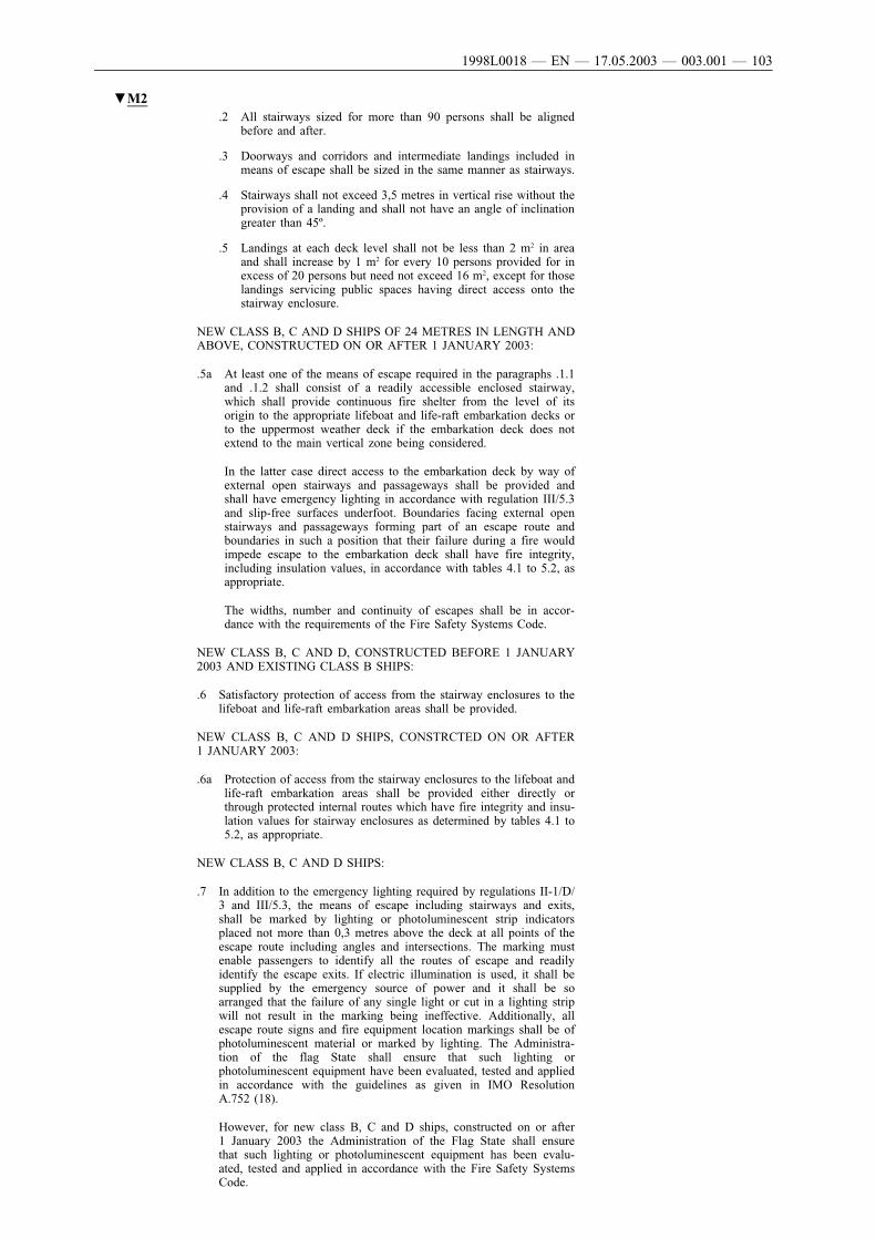
▼M2.2 All stairways sized for more than 90 persons shall be aligned
before and after.
.3 Doorways and corridors and intermediate landings included inmeans of escape shall be sized in the same manner as stairways.
.4 Stairways shall not exceed 3,5 metres in vertical rise without theprovision of a landing and shall not have an angle of inclinationgreater than 45º.
.5 Landings at each deck level shall not be less than 2 m2 in areaand shall increase by 1 m2 for every 10 persons provided for inexcess of 20 persons but need not exceed 16 m2, except for thoselandings servicing public spaces having direct access onto thestairway enclosure.
NEW CLASS B, C AND D SHIPS OF 24 METRES IN LENGTH ANDABOVE, CONSTRUCTED ON OR AFTER 1 JANUARY 2003:
.5a At least one of the means of escape required in the paragraphs .1.1and .1.2 shall consist of a readily accessible enclosed stairway,which shall provide continuous fire shelter from the level of itsorigin to the appropriate lifeboat and life-raft embarkation decks orto the uppermost weather deck if the embarkation deck does notextend to the main vertical zone being considered.
In the latter case direct access to the embarkation deck by way ofexternal open stairways and passageways shall be provided andshall have emergency lighting in accordance with regulation III/5.3and slip-free surfaces underfoot. Boundaries facing external openstairways and passageways forming part of an escape route andboundaries in such a position that their failure during a fire wouldimpede escape to the embarkation deck shall have fire integrity,including insulation values, in accordance with tables 4.1 to 5.2, asappropriate.
The widths, number and continuity of escapes shall be in accor-dance with the requirements of the Fire Safety Systems Code.
NEW CLASS B, C AND D, CONSTRUCTED BEFORE 1 JANUARY2003 AND EXISTING CLASS B SHIPS:
.6 Satisfactory protection of access from the stairway enclosures to thelifeboat and life-raft embarkation areas shall be provided.
NEW CLASS B, C AND D SHIPS, CONSTRCTED ON OR AFTER1 JANUARY 2003:
.6a Protection of access from the stairway enclosures to the lifeboat andlife-raft embarkation areas shall be provided either directly orthrough protected internal routes which have fire integrity and insu-lation values for stairway enclosures as determined by tables 4.1 to5.2, as appropriate.
NEW CLASS B, C AND D SHIPS:
.7 In addition to the emergency lighting required by regulations II-1/D/3 and III/5.3, the means of escape including stairways and exits,shall be marked by lighting or photoluminescent strip indicatorsplaced not more than 0,3 metres above the deck at all points of theescape route including angles and intersections. The marking mustenable passengers to identify all the routes of escape and readilyidentify the escape exits. If electric illumination is used, it shall besupplied by the emergency source of power and it shall be soarranged that the failure of any single light or cut in a lighting stripwill not result in the marking being ineffective. Additionally, allescape route signs and fire equipment location markings shall be ofphotoluminescent material or marked by lighting. The Administra-tion of the flag State shall ensure that such lighting orphotoluminescent equipment have been evaluated, tested and appliedin accordance with the guidelines as given in IMO ResolutionA.752 (18).
However, for new class B, C and D ships, constructed on or after1 January 2003 the Administration of the Flag State shall ensurethat such lighting or photoluminescent equipment has been evalu-ated, tested and applied in accordance with the Fire Safety SystemsCode.
1998L0018 — EN — 17.05.2003 — 003.001 — 103

▼M2NEW CLASS B, C AND D SHIPS, CONSTRUCTED ON OR AFTER1 JANUARY 2003:
.8 In ships carrying more than 36 passengers the requirements ofparagraph .1.7 of this regulation shall also apply to the crew accom-modations.
.9 Normally locked doors that form part of an escape route.
.1 Cabin and stateroom doors shall not require keys to unlock themfrom inside the room.
Neither shall there be any doors along any designated escaperoute which require keys to unlock them when moving in thedirection of escape.
.2 Escape doors from public spaces that are normally latched shallbe fitted with a means of quick release. Such means shall consistof a door-latching mechanism incorporating a device thatreleases the latch upon the application of a force in the directionof escape flow. Quick release mechanisms shall be designed andinstalled to the satisfaction of the Administration of the flagState and in particular:
.2.1 consist of bars or panels, the actuating portion of whichextends across at least one half of the width of the doorleaf, at least 760 mm and not more than 1 120 mm abovethe deck;
.2.2 cause the door latch to release when a force not exceeding67 N is applied; and
.2.3 not be equipped with any locking device, set screw orother arrangement that prevents the release of the latchwhen pressure is applied to the releasing device.
NEW CLASS B, C AND D AND EXISTING CLASS B SHIPS:
.2 .1 In special category spaces the number and disposition of the meansof escape both below and above the bulkhead deck shall be to thesatisfaction of the Administration of the flag State and in generalthe safety of access to the embarkation deck shall be at least equiva-lent to that provided under paragraphs .1.1, .1.2, .1.5 and .1.6.
In new class B, C and D ships, constructed on or after 1 January2003, such spaces shall be provided with designated walkways tothe means of escape with a breadth of at least 600 mm, and wherepracticable and reasonable those designated longitudinal walkwaysshall raise at least 150 mm above the deck surface. The parkingarrangements for the vehicles shall maintain the walkways clear atall times.
.2 One of the escape routes from the machinery spaces where the crewis normally employed shall avoid direct access to any special cate-gory space.
.3 Hoistable drive-up/down ramps to platform decks must not becapable of blocking the approved escape routes when in loweredposition.
.3.1 Two means of escape shall be provided from each machinery space. Inparticular, the following provisions shall be complied with:
.1 Where the space is below the bulkhead deck the two means ofescape shall consist of either:
.1 two sets of steel ladders as widely separated as possible,leading to doors in the upper part of the space similarly sepa-rated and from which there is access to the appropriate lifeboatand life-raft embarkation decks. In new ships, one of theseladders shall provide continuous fire shelter from the lowerpart of the space to a safe position outside the space. In newclass B, C and D ships, constructed on or after 1 January 2003that ladder shall be located within a protected enclosure thatsatisfies regulation II-2/B/4, category (2) or II-2/B/5,category (4), as appropriate, from the lower part of the spaceit serves to a safe position outside the space. Self-closing firedoors of the same fire integrity standards shall be fitted in theenclosure. The ladder shall be fixed in such a way that heat isnot transferred into the enclosure through non-insulated fixingpoints. The protected enclosure shall have minimum internaldimensions of at least 800 mm × 800 mm, and shall haveemergency lighting provisions; or
1998L0018 — EN — 17.05.2003 — 003.001 — 104

▼M2.2 one steel ladder leading to a door from which access is
provided to the embarkation deck and additionally, in thelower part of the space and in a position well separated fromthe ladder referred to, a steel door capable of being operatedfrom each side and which provides access to a safe escaperoute from the lower part of the space to the embarkationdeck.
.2 Where the space is above the bulkhead deck, the two means ofescape shall be as widely separated as possible and the doorsleading from such means of escape shall be a position from whichaccess is provided to the appropriate lifeboat and life-raft embarka-tion decks. Where such means of escape require the use of ladders,these shall be of steel.
NEW CLASS A, B, C AND D SHIPS:
.3 From spaces for monitoring of operation of machinery, and fromwork spaces, there shall be at least two means of escape, of whichone shall be independent of the machinery space and give accessto the embarkation deck.
.4 The underside of stairs in machinery spaces shall be shielded.
NEW CLASS B, C AND D AND EXISTING CLASS B SHIPS:
.3.2 In a ship of less than 24 metres in length, the Administration of the flagState may dispense with one of the means of escape in machinery spaces,due regard being paid to the width and disposition of the upper part ofthe space.
In a ship of 24 metres in length and above, the Administration of the flagState may dispense with one means of escape from any such space solong as either a door or a steel ladder provides a safe escape route tothe embarkation deck, due regard being paid to the nature and locationof the space and whether persons are normally employed in that space.In new class B, C and D ships, constructed on or after 1 January 2003,a second means of escape shall be provided in the steering gear spacewhen the emergency steering position is located in that space unlessthere is a direct access to the open deck.
.3.3 Two means of escape shall be provided from a machinery control roomlocated within a machinery space, at least one of which will providecontinuous fire shelter to a safe position outside the machinery space.
.4 In no case shall lifts be considered as forming one of the required meansof escape.
.5 NEW CLASS B, C AND D AND EXISTING CLASS B SHIPS OF40 METRES IN LENGTH AND ABOVE:
.1 Emergency escape breathing devices shall be carried, complyingwith the Fire Safety Systems Code.
.2 At least two emergency escape breathing devices shall be carriedin each main vertical zone
.3 In ships carrying more than 36 passengers, two emergency escapebreathing devices, in addition to those required in subparagraph .5.2shall be carried in each main vertical zone.
.4 However, subparagraphs .5.2 and .5.3 do not apply to stairwayenclosures which constitute individual main vertical zones and forthe main vertical zones in the fore or aft end of a ship, which donot contain spaces of categories (6), (7), (8) or (12) defined inregulation II-2/B/4.
.5 Within the machinery spaces, emergency escape breathing devicesshall be situated ready for use at easily visible places, which canbe reached quickly and easily at any time in the event of fire.The location of emergency escape breathing devices shall takeinto account the layout of the machinery space and the number ofpersons normally working in the space.
.6 Reference is made to the IMO Guidelines for the performance,location , use and care of emergency breathing devices. (MSC/Circ. 849).
.7 The number and location of these devices shall be indicated in thefire control plan required in regulation II-2/A/13.
1998L0018 — EN — 17.05.2003 — 003.001 — 105

▼M26-1 Escape routes on ro-ro passenger ships (R 28-1)
.1 REQUIREMENTS APPLICABLE TO NEW CLASS B, C AND D ANDEXISTING CLASS B RO-RO PASSENGER SHIPS
.1.1 This paragraph applies to new class B, C and D and existing class B ro-ro passenger ships. For existing ships the requirements of the regulationshall apply not later than the date of the first periodical survey after thedate referred to in paragraph .1 of regulation II-2/B/16.
.1.2 Handrails or other handholds shall be provided in all corridors along theentire escape route, so that a firm handhold is available every step of theway, where possible, to the assembly stations and embarkation stations.Such handrails shall be provided on both sides of longitudinal corridorsmore than 1,8 metres in width and transverse corridors more than 1 metrein width. Particular attention shall be paid to the need to be able to crosslobbies, atriums and other large open spaces along escape routes. Hand-rails and other handholds shall be of such strength as to withstand adistributed horizontal load of 750 N/m applied in the direction of thecentre of the corridor or space, and a distributed vertical load of 750 N/m applied in the downward direction. The two loads need not be appliedsimultaneously.
.1.3 Escape routes shall not be obstructed by furniture or other obstructions.With the exception of tables and chairs which may be cleared to provideopen space, cabinets and other heavy furnishings in public spaces andalong escape routes shall be secured in place to prevent shifting if theship rolls or lists. Floor coverings shall also be secured in place. Whenthe ship is underway, escape routes shall be kept clear of obstructionssuch as cleaning carts, bedding, luggage and boxes of goods.
.1.4 Escape routes shall be provided from every normally occupied space onthe ship to an assembly station. These escape routes shall be arranged soas to provide the most direct route possible to the assembly station, andshall be marked with symbols related to life-saving appliances andarrangements, adopted by IMO by Resolution A.760 (18).
.1.5 Where enclosed spaces adjoin an open deck, openings from the enclosedspace to the open deck shall, where practicable, be capable of being usedas an emergency exit.
.1.6 Decks shall be sequentially numbered, starting with ‘1’ at the tank top orlowest deck. These numbers shall be prominently displayed at stair land-ings and lift lobbies. Decks may also be named, but the deck numbershall always be displayed with the name.
.1.7 Simple ‘mimic’ plans showing the ‘you are here’ position and escaperoutes marked by arrows shall be prominently displayed on the inside ofeach cabin door and in public spaces. The plan shall show the directionsof escape, and shall be properly oriented in relation to its position on theship.
.1.8 Cabin and stateroom doors shall not require keys to unlock them frominside the room. Neither shall there be any doors along any designedescape route which require keys to unlock them when moving in thedirection of escape.
.2 REQUIREMENTS APPLICABLE TO NEW CLASS B, C AND D RO-RO PASSENGER SHIPS
.2.1 The lowest 0,5 metres of bulkheads and other partitions forming verticaldivisions along escape routes shall be able to sustain a load of 750 N/m2
to allow them to be used as walking surfaces from the side of the escaperoute with the ship at large angles of heel.
.2.2 The escape route from cabins to stairway enclosures shall be as direct aspossible, with a minimum number of changes in direction. It shall not benecessary to cross from one side of the ship to the other to reach anescape route. It shall not be necessary to climb more than two decks upor down in order to reach an assembly station or open deck from anypassenger space.
.2.3 External routes shall be provided from open decks, referred to inparagraph 2.2, to the survival craft embarkation stations.
1998L0018 — EN — 17.05.2003 — 003.001 — 106
▼M2.3 REQUIREMENTS APPLICABLE TO NEW CLASS B, C AND D RO-
RO PASSENGER SHIPS CONSTRUCTED ON OR AFTER 1 JULY1999
For new class B, C and D ro-ro passenger ships constructed on or after1 July 1999, escape routes shall be evaluated by an evacuation analysisearly in the design process. The analysis shall be used to identify andeliminate, as far as practicable, congestion which may develop duringan abandonment, due to normal movement of passengers and crew alongescape routes, including the possibility that crew may need to movealong these routes in a direction opposite the movement of the passen-gers. In addition, the analysis shall be used to demonstrate that escapearrangements are sufficiently flexible to provide for the possibility thatcertain escape routes, assembly stations, embarkation stations or survivalcraft may not be available as a result of a casualty.
7 Penetrations and openings in ‘A’ and ‘B’ class divisions (R 30, 31)
NEW CLASS B, C AND D AND EXISTING CLASS B SHIPS:
.1 All openings in ‘A’ class divisions shall be provided with permanentlyattached means of closing which shall be as effective for resisting firesas the divisions in which they are fitted.
.2 The construction of all doors and door frames in ‘A’ class divisions, withthe means of securing them when closed, shall provide resistance to fireas well as to the passage of smoke and flame, as far as practicable,equivalent to that of the bulkheads in which the doors are situated. Suchdoors and doorframes shall be constructed of steel or other equivalentmaterial. Watertight doors need not be insulated.
.3 It shall be possible for each door to be opened and closed from each sideof the bulkhead by one person only.
.4 Fire doors in main vertical zone bulkheads and stairways enclosuresother than power-operated sliding watertight doors and doors normallylocked, shall satisfy the following requirements:
.1 The doors shall be self-closing and be capable of closing with anangle of up to 3,5º opposing closure. The speed of closure shall, ifnecessary, be controlled so as to prevent undue danger to persons.In new ships the uniform rate of closure shall be no more than0,2 m/s and no less than 0,1 m/s with the ship in the upright position.
NEW CLASS B, C AND D SHIPS:
.2 Remote-controlled sliding or power-operated doors shall be equippedwith an alarm that sounds at least 5 seconds but no more than 10seconds before the door begins to move and continue sounding untilthe door is completely closed. Doors designed to re-open uponcontacting an object in its path shall re-open sufficiently to allow aclear passage of at least 0,75 metres, but no more than one metre.
.3 All doors, except fire doors which are normally kept closed, shall becapable of remote and automatic release from a continuouslymanned central control station, either simultaneously or in groups,and also individually from a position at both sides of the door. Indi-cation must be provided at the fire control panel in the continuouslymanned central control station whether each of the remote-controlleddoors is closed. The release mechanism shall be so designed that thedoor will automatically close in the event of disruption of the controlsystem or central power supply. Release switches shall have an on-off function to prevent automatic resetting of the system. Holdbackhooks not subject to central control station release are prohibited.
.4 Local power accumulators for power-operated doors shall beprovided in the immediate vicinity of the doors to enable the doorsto be operated at least 10 times (fully opened and closed) using thelocal controls.
.5 Double-leaf doors equipped with a latch necessary to their fire integ-rity shall have a latch that is automatically activated by the operationof the doors when released by the system.
.6 Doors giving direct access to special category spaces which arepower-operated and automatically closed need not be equipped withalarms and remote-release mechanisms required in .4.2 and .4.3.
1998L0018 — EN — 17.05.2003 — 003.001 — 107

▼M2CLASS B, C AND D SHIPS CONSTRUCTED ON OR AFTER 1 JANUARY2003:
Instead of .4 the following paragraph .4a shall apply
.4a Fire doors in main vertical zone bulkheads, galley boundaries andstairway enclosures other than power-operated watertight doors and thosewhich are normally locked, shall satisfy the following requirements:
.1 the doors shall be self-closing and be capable of closing against anangle of inclination of up to 3,5º opposing closure;
.2 the approximate time of closure for hinged fire doors shall be nomore than 40 seconds and no less than 10 seconds from the begin-ning of their movement with the ship in upright position. Theapproximate uniform rate of closure for sliding fire doors shall beof no more than 0,2 m/s and no less than 0,1 m/s with the ship inthe upright position;
.3 the doors shall be capable of remote release from the continuouslymanned central control station, either simultaneously or in groupsand shall be capable of release also individually from a position atboth sides of the door. Release switches shall have an on-off func-tion to prevent automatic resetting of the system;
.4 hold-back hooks not subject to central control station release areprohibited;
.5 a door closed remotely from the central control station shall becapable of being reopened at both sides of the door by localcontrol. After such local opening the door shall automatically closeagain;
.6 indication shall be provided at the fire door indicator panel in thecontinuously manned central control station whether each of theremote-released doors are closed;
.7 the release mechanism shall be so designed that the door will auto-matically close in the event of disruption of the control system ormain source of electric power;
.8 local power accumulators for power-operated doors shall beprovided in the immediate vicinity of the doors to enable the doorsto be operated after disruption of the control system or main sourceof electric power at least 10 times (fully opened or closed) usingthe local controls;
.9 disruption of the control system or main source of electric power atone door shall not impair the safe functioning of the other doors;
.10 remote-released sliding or power-operated doors shall be equippedwith an alarm that sounds for at least 5 seconds but no more than10 seconds after the door is released from the central control stationand before the door begins to move and continue sounding until thedoor is completely closed;
.11 a door designed to re-open upon contacting an object in its pathshall re-open not more than one metre from the point of contact;
.12 double-leaf doors equipped with latch necessary to their fire integ-rity shall have a latch that is automatically activated by theoperation of the doors when released by the control system;
.13 doors giving direct access to special category spaces which arepower-operated and automatically closed need not be equippedwith the alarms and remote-release mechanisms required inparagraph .3 and .10;
.14 the components of the local control system shall be accessible formaintenance and adjusting; and
.15 power-operated doors shall be provided with a control system of anapproved type which shall be able to operate in case of fire, thisbeing determined in accordance with the Fire Test ProcedureCode. This system shall satisfy the following requirements:
.15.1 the control system shall be able to operate the door at atemperature of at least 200 ºC for at least 60 minutes, servedby the power supply;
.15.2 the power supply for all other doors not subject to fire shallnot be impaired, and;
.15.3 at temperatures exceeding 200 ºC the control system shallbe automatically isolated from the power supply and shallbe capable of keeping the door closed up to at least 945 ºC.
1998L0018 — EN — 17.05.2003 — 003.001 — 108

▼M2NEW CLASS B, C AND D SHIPS:
.5 The requirements for ‘A’ class integrity of the outer boundaries of a shipshall not apply to glass partitions, windows and sidescuttles, providedthat there is no requirement for such boundaries to have ‘A’ class integ-rity in regulation 10. Similarly, the requirements for ‘A’ class integrityshall not apply to exterior doors in superstructures and deckhouses.
CLASS B, C AND D SHIPS, CONSTRUCTED ON OR AFTER 1 JANUARY2003:
Instead of .5: the following paragraph .5a shall apply:
.5a The requirements for ‘A’ class integrity of the outer boundaries of a shipshall not apply to glass partitions, windows and sidescuttles, providedthat there is no requirement for such boundaries to have a ‘A’ classintegrity in regulation 10.
The requirements for ‘A’ class integrity of the outer boundaries of theship shall not apply to exterior doors, except for those in superstructuresand deckhouses facing life-saving appliances. embarkation and externalassembly station areas, external stairs and open decks used for escaperoutes. Stairway enclosure doors need not meet this requirement.
NEW CLASS B, C AND D SHIPS:
.6 Except for watertight doors, weathertight doors (semi-watertight doors),doors leading to the open deck and doors which need to be reasonablygastight all ‘A’ class doors located in stairways, public spaces and mainvertical zone bulkheads in escape routes shall be equipped with a self-closing hose port of material, construction and fire resistance which isequivalent to the door into which it is fitted, and shall be a 150 mmsquare clear opening with the door closed and shall be inset into thelower edge of the door, opposite to the door hinges, or in the case ofsliding doors, nearest the opening.
NEW CLASS B, C AND D AND EXISTING CLASS B SHIPS:
.7 Doors and door frames in ‘B’ class divisions and means of securing themshall provide a method of closure which shall have resistance to fireequivalent to that of the divisions except that ventilation openings maybe permitted in the lower portion of such doors. Where such opening isin or under a door the total net area of any such opening or openingsshall not exceed 0,05 m2. Alternatively, a non-combustible air balanceduct routed between the cabin and the corridor and located below thesanitary unit is permitted where the cross-sectional area of the duct doesnot exceed 0,05 m2. All ventilation openings shall be fitted with a grillmade of non-combustible material. Doors shall be non combustible.
.7.1 For reasons of noise reduction, the Administration may approve, as anequivalent, doors with built-in ventilation sound-locks with openings atthe bottom on one side of the door and at the top on the other side, oncondition that the following provisions have been complied with:
.1 The upper opening shall always face towards the corridor and shallbe provided with a grating of non-combustible material and an auto-matically operating fire damper, which is activated at a temperatureof about 70 ºC.
.2 The lower opening shall be provided with a grating made of a non-combustible material.
.3 The doors shall be tested in accordance with Resolution A.754 (18).
NEW CLASS B, C AND D SHIPS:
.8 Cabin doors in ‘B’ class divisions shall be of a self-closing type. Hold-backs are not permitted.
NEW CLASS B,C AND D AND EXISTING CLASS B SHIPS:
.9 The requirements for ‘B’ class integrity of the outer boundaries of a shipshall not apply to glass partitions, windows and sidescuttles. Similarlythe requirements for ‘B’ class integrity shall not apply to exterior doorsin superstructures and deckhouses. For ships carrying not more than 36passengers, the Administration of the flag State may permit the use ofcombustible materials in doors separating cabins from the individualinterior sanitary spaces such as showers.
1998L0018 — EN — 17.05.2003 — 003.001 — 109

▼M28 Protection of stairways and lifts in accommodation and service spaces
(R 29)
NEW CLASS B, C AND D SHIPS:
.1 All stairways shall be of steel frame construction and shall be withinenclosures formed of ‘A’ class divisions, with positive means of closureof all openings except that:
.1 a stairway connecting only two decks need not be enclosed, providedthe integrity of the deck is maintained by proper bulkheads or doorsin one between-deck space. When a stairway is closed in onebetween-deck space, the stairway enclosure shall be protected inaccordance with the tables for decks in regulations 4 and 5;
.2 stairways may be fitted in the open in a public space, provided theylie wholly within such public space.
NEW CLASS B, C AND D AND EXISTING CLASS B SHIPS:
.2 Stairway enclosures shall have direct access with the corridors and be ofa sufficient area to prevent congestion, having in view the number ofpersons likely to use them in an emergency.
NEW CLASS B, C AND D SHIPS: Within the perimeter of suchstairway enclosures only public toilets, lockers of non-combustible mate-rial providing storage for safety equipment and open informationcounters are permitted.
Only public spaces, corridors, public toilets, special category spaces,other escape stairways required by regulation 6-1.5 and external areasare permitted to have direct access to these stairway enclosures.
NEW CLASS B, C AND D AND EXISTING CLASS B SHIPS:
.3 Lift trunks shall be so fitted as to prevent the passage of smoke andflame from one between-deck to another and shall be provided withmeans of closing so as to permit the control of draught and smoke.
9 Ventilation systems (R 32)
.1 Ships carrying more than 36 passengers
NEW CLASS B, C AND D SHIPS:
.1 The ventilation system shall, in addition to paragraph .1 of this regu-lation, also be in compliance with subparagraphs .2.2 to .2.6, .2.8and .2.9 of this regulation.
NEW CLASS B, C AND D AND EXISTING CLASS B SHIPS:
.2 In general, the ventilation fans shall be so disposed that the ductsreaching the various spaces remain within the main vertical zone.
.3 Where ventilation systems penetrate decks, precautions shall betaken, in addition to those relating to fire integrity of the deckrequired by regulation II-2/A/12.1, to reduce the likelihood of smokeand hot gases passing from one between-deck space to anotherthrough the system. In addition to insulation requirements containedin this regulation, vertical ducts shall, if necessary, be insulated asrequired by the appropriate tables in regulation 4.
NEW CLASS B, C AND D SHIPS:
.4 Ventilation ducts shall be constructed of the following materials:
.1 ducts not less than 0,075 m2 in sectional area and all vertical ductsserving more than a single between-deck space shall be constructedof steel or other equivalent material;
.2 ducts less than 0,075 m2 in sectional area other than vertical ductsreferred to in subparagraph .1.4.1, shall be constructed of non-combustible materials. Where such ducts penetrate ‘A’ or ‘B’ classdivisions due regard shall be given to ensuring the fire integrity ofthe division;
1998L0018 — EN — 17.05.2003 — 003.001 — 110

▼M2.3 short lengths of duct, not in general exceeding 0,02 m2 in sectional
area nor two metres in length, need not be non-combustible providedthat all of the following conditions are met:
.1 the duct is constructed of a material of low fire risk to the satis-faction of the Administration of the flag State;
.2 the duct is used only at the terminal end of the ventilationsystem, and
.3 the duct is not located closer than 600 mm measured along itslength to a penetration of an ‘A’ or ‘B’ class division, includingcontinuous ‘B’ class ceilings.
CLASS B, C AND D SHIPS, CONSTRUCTED ON OR AFTER1 JANUARY 2003:
instead of subparagraph .1 the following subparagraph .1a shallapply:
.1a the duct shall be of a material which has low flame spreadcharacteristics.
.5 Stairway enclosures shall be ventilated and shall be served only by anindependent fan and duct system which shall not serve any other spacesin the ventilation system.
NEW CLASS B, C AND D AND EXISTING CLASS B SHIPS:
.6 All power ventilation, except machinery space and cargo space ventila-tion and any alternative system which may be required undersubparagraph .9.2.6, shall be fitted with controls so grouped that all fansmay be stopped from either of two separate positions which shall be situ-ated as far apart as practicable. Controls provided for the powerventilation serving machinery spaces shall also be grouped so as to beoperable from two positions, one of which shall be outside such spaces.Fans serving power ventilation systems to cargo spaces shall be capableof being stopped from a safe position outside such spaces.
NEW CLASS B, C AND D SHIPS:
.7 Where public spaces span three or more open decks and contain combus-tibles such as furniture and enclosed spaces such as shops, offices andrestaurants, the space shall be equipped with a smoke extraction system.The smoke extraction system shall be activated by the required smokedetection system and be capable of manual control. The fans shall besized such that the entire volume within the space can be exhausted in10 minutes or less.
.8 Ventilation ducts shall be provided with suitably located hatches forinspection and cleaning, where reasonable and practicable.
.9 Exhaust ducts from galley ranges in which grease or fat is likely to accu-mulate shall meet requirements of subparagraphs .9.2.3.2.1 and .9.2.3.2.2and shall be fitted with:
.1 a grease trap readily removable for cleaning unless an alternativeapproved grease removal system is fitted;
.2 a fire damper located in the lower end of the duct which is automa-tically and remotely operated, and in addition a remotely operatedfire damper located in the upper end of the duct;
.3 a fixed means for extinguishing a fire within the duct;
.4 remote control arrangements for shutting off the exhaust fans andsupply fans, for operating the fire dampers mentioned in .2 and foroperating the fire-extinguishing system, which shall be placed in aposition close to the entrance to the galley. Where a multi-branchsystem is installed, means shall be provided to close all branchesexhausting through the same main duct before an extinguishingmedium is released into the system; and
.5 suitably located hatches for inspection and cleaning.
.2 Ships carrying not more than 36 passengers
NEW CLASS B, C AND D SHIPS:
.1 Ventilation ducts shall be of non-combustible material. Short ducts,however, not generally exceeding two metres in length and with a
1998L0018 — EN — 17.05.2003 — 003.001 — 111

▼M2cross-section not exceeding 0,02 m2 need not be non-combustible,subject to the following conditions:
.1 these ducts shall be of a material which, in the opinion of theAdministration of the flag State, has a low fire risk;
.2 they may only be used at the end of the ventilation device;
.3 they shall not be situated less than 600 mm, measured along theduct, from an opening in an ‘A’ or ‘B’ class division, includingcontinuous ‘B’ class ceilings.
CLASS B, C AND D SHIPS CONSTRUCTED ON OR AFTER1 JANUARY 2003:
instead of subparagraph .1 the following subparagraph .1a shallapply:
.1a these ducts shall be of a material which has low flamespread characteristics.
.2a Where the ventilation ducts with a free-sectional area exceeding0,02 m2 pass through class ‘A’ bulkheads or decks, the openingsshall be lined with a steel sheet sleeve unless the ducts passingthrough the bulkheads or decks are of steel in the vicinity ofpassage through the deck or bulkhead and the ducts and sleevesshall comply in this part with the following:
.1 The sleeves shall have a thickness of at least 3 mm and alength of at least 900 mm. When passing through bulkheads,this length shall be divided preferably into 450 mm on eachside of the bulkhead. These ducts, or sleeves lining such ducts,shall be provided with fire insulation. The insulation shall haveat least the same fire integrity as the bulkhead or deck throughwhich the duct passes.
.2 Ducts with a free cross-sectional area exceeding 0,075 m2 shallbe fitted with fire dampers in addition to the requirements ofsub-paragraph .9.2.2.1. The fire damper shall operate automati-cally but shall also be capable of being closed manually fromboth sides of the bulkhead or deck. The damper shall beprovided with an indicator which shows whether the damper isopen or closed. Fire dampers are not required, however, whereducts pass through spaces surrounded by ‘A’ class divisions,without serving those spaces, provided those ducts have thesame fire integrity as the divisions which they pierce. Firedampers shall be easily accessible. In new class B, C and Dships, constructed on or after 1 January 2003 where firedampers are placed behind ceilings or linings, these ceilings orlinings shall be provided with an inspection door on which aplate reporting the identification number of the fire damper isprovided. The fire damper identification number shall also beplaced on any remote controls required.
.2b In new class B, C and D ships, constructed on or after 1 January2003,where a thin plated duct with a free cross-sectional area equalto or less than 0,02 m2 passes through ‘A’ class bulkheads or decks,the opening shall be lined with a steel sleeve having a thickness ofat least 3 mm and a length of at least 200 mm, divided preferablyinto 100 mm on each side of the bulkhead or, in the case of thedeck, wholly laid on the lower side of the decks pierced.
.3 Ducts provided for the ventilation of machinery spaces, galleys, cardeck spaces, ro-ro cargo spaces or special category spaces shall notpass through accommodation spaces, service spaces or controlstations unless they comply with the conditions specified insubparagraphs .9.2.3.1.1 to .9.2.3.1.4 or .9.2.3.2.1 and .9.2.3.2.2:
.1.1 the ducts are constructed of steel having a thickness of at least3 mm and 5 mm for ducts the widths or diameters of whichare up to and including 300 mm and 760 mm and over respec-tively and, in the case of such ducts, the widths or diameters ofwhich are between 300 mm and 760 mm having a thickness tobe obtained by interpolation;
.1.2 the ducts are suitably supported and stiffened;
.1.3 the ducts are fitted with automatic fire dampers close to theboundaries penetrated; and
.1.4 the ducts are insulated to ‘A-60’ standard from the machineryspaces, galleys, car deck spaces, ro-ro cargo spaces or specialcategory spaces to a point at least 5 metres beyond each firedamper;
1998L0018 — EN — 17.05.2003 — 003.001 — 112

▼M2or
.2.1 the ducts are constructed of steel in accordance with para-graphs .9.2.3.1.1 and .9.2.3.1.2; and
.2.2 the ducts are insulated to ‘A-60’ standard throughout theaccommodation spaces, service spaces or control stations;
except that penetrations of main zone divisions shall alsocomply with the requirements of subparagraph .9.2.8.
In new class B, C and D ships, constructed on or after1 January 2003 the ventilation systems for machinery spacesof category A, vehicle spaces, ro-ro spaces, galleys, specialcategory spaces and cargo spaces shall, in general, be sepa-rated from each other and from the ventilation systemsserving other spaces. Except that the galley ventilation systemson passenger ships carrying not more than 36 passengers neednot be completely separated, but may be served by separateducts from a ventilation unit serving other spaces. In any casean automatic fire damper shall be fitted in the galley ventila-tion duct near the ventilation unit.
.4 Ducts provided for ventilation to accommodation spaces, servicespaces or control stations shall not pass through machinery spaces,galleys, car deck spaces, ro-ro cargo spaces or special categoryspaces unless they comply with the conditions specified insubparagraphs .9.2.4.1.1 to .9.2.4.1.3 or .9.2.4.2.1 and .9.2.4.2.2:
.1.1 the ducts where they pass through a machinery space, galley,car deck space, ro-ro cargo space or special category spaceare constructed of steel in accordance withsubparagraphs .9.2.3.1.1 and .9.2.3.1.2;
.1.2 automatic fire dampers are fitted close to the boundaries pene-trated; and
.1.3 the integrity of the machinery space, galley, car deck space,ro-ro cargo space or special category space boundaries ismaintained at the penetrations;
or
.2.1 the ducts where they pass through a machinery space, galley,car deck space, ro-ro cargo space or special category spaceare constructed of steel in accordance withsubparagraphs .9.2.3.1.1 and .9.2.3.1.2; and
.2.2 the ducts are insulated to ‘A-60’ standard throughout themachinery space, galley, car deck space, ro-ro cargo space orspecial category space;
except that penetrations of main zone divisions shall alsocomply with the requirements of subparagraph .9.2.8.
.5 Ventilation ducts with a free-sectional area exceeding 0,02 m2
passing through class ‘B’ bulkheads shall be lined with steel sheetsleeves of 900 mm in length divided preferably into 450 mm oneach side of the bulkheads unless the duct is of steel for this length.
.6 Such measures as are practicable shall be taken in respect of controlstations outside machinery spaces in order to ensure that ventilation,visibility and freedom from smoke are maintained, so that in theevent of fire the machinery and equipment contained therein maybe supervised and continue to function effectively. Alternative andseparate means of air supply shall be provided; air inlets of the twosources of supply shall be so disposed that the risk of both inletsdrawing in smoke simultaneously is minimised. Such requirementsneed not apply to control stations situated on, and opening on to, anopen deck, or where local closing arrangements would be equallyeffective.
.7 Where they pass through accommodation spaces or spacescontaining combustible materials, the exhaust ducts from galleyranges shall be constructed of ‘A’ class divisions. Each exhaustduct shall be fitted with:
.1 a grease trap readily removable for cleaning;
.2 a fire damper located in the lower end of the duct;
.3 arrangements, operable from within the galley, for shutting offthe exhaust fans; and
.4 fixed means for extinguishing a fire within the duct.
1998L0018 — EN — 17.05.2003 — 003.001 — 113

▼M2.8 Where it is necessary that a ventilation duct passes through a main
vertical zone division, a fail-safe automatic closing fire damper shallbe fitted adjacent to the division. The damper shall also be capableof being manually closed from each side of the division. The oper-ating position shall be readily accessible and be marked in red light-reflecting colour. The duct between the division and the damper shallbe of steel or other equivalent material and, if necessary, insulated tocomply with the requirements of regulation II 2/A/12.1. The dampershall be fitted on at least one side of the division with a visible indi-cator showing whether the damper is in the open position.
NEW CLASS B, C AND D AND EXISTING CLASS B SHIPS:
.9 The main inlets and outlets of all ventilation systems shall becapable of being closed from outside the spaces being ventilated.
NEW CLASS B, C AND D SHIPS:
.10 Power ventilation of accommodation spaces, service spaces, cargospaces, control stations and machinery spaces shall be capable ofbeing stopped from an easily accessible position outside the spacebeing served. This position should not be readily cut off in theevent of a fire in the spaces served. The means provided for stop-ping the power ventilation of the machinery spaces shall be entirelyseparate from the means provided for stopping ventilation of otherspaces.
.3 ALL CLASS B,C AND D SHIPS, CONSTRUCTED ON OR AFTER1 JANUARY 2003:
The following arrangements shall be tested in accordance with the IMOFire Test Procedures Code:
.1 fire dampers including relevant means of operation; and
.2 duct penetrations through ‘A’ class divisions. Where steel sleeves aredirectly joined to ventilation ducts by means of riveted or screwedflanges or by welding, the test is not required.
10 Windows and sidescuttles (R 33)
NEW CLASS B, C AND D AND EXISTING CLASS B SHIPS:
.1 All windows and sidescuttles in bulkheads within accommodation andservice spaces and control stations other than those to which the provi-sions of regulation 7.5 apply, shall be so constructed as to preserve theintegrity requirements of the type of bulkheads in which they are fitted.
In new class B, C and D ships, constructed on or after 1 January 2003this shall be determined in accordance with the Fire Test ProceduresCode.
.2 Notwithstanding the requirements of the tables in regulations 4 and 5, allwindows and sidescuttles in bulkheads separating accommodation andservice spaces and control stations from weather shall be constructedwith frames of steel or other suitable material. The glass shall be retainedby a metal glazing bed or angle.
NEW CLASS B, C AND D SHIPS CARRYING MORE THAN 36 PASSEN-GERS:
.3 Windows facing life-saving appliances, embarkation and assembly areas,external stairs and open decks used for escape routes, and windows situ-ated below life-raft and escape slide embarkation areas shall have the fireintegrity as required in the tables of regulation 4. Where automatic dedi-cated sprinkler heads are provided for windows, ‘A-0’ windows may beaccepted as equivalent
In new class B, C and D ships, constructed on or after 1 January 2003,the automatic dedicated sprinkler heads must either be:
.1 dedicated heads located above the windows and installed in additionto the conventional ceiling sprinklers; or
.2 conventional ceiling sprinkler heads arranged such that the windowis protected by an average application rate of at least 5 litres/m2 perminute and the additional window area is included in the calculationof the area of coverage.
1998L0018 — EN — 17.05.2003 — 003.001 — 114

▼M2Windows located in the ship's side below the lifeboat embarkation areasshall have the fire integrity at least equal to ‘A-0’ class.
NEW CLASS B, C AND D SHIPS CARRYING NOT MORE THAN 36PASSENGERS AND EXISTING CLASS B SHIPS:
.4 Notwithstanding the requirements of the tables in regulation II-2/B/5,special attention shall be given to the fire integrity of windows facingopen or enclosed lifeboat and life-raft embarkation areas and to the fireintegrity of windows situated below such areas in such a position thattheir failure during a fire would impeded the launching of, or embarka-tion into, lifeboats or life-rafts.
11 Restricted use of combustible material (R 34)
NEW CLASS B, C AND D SHIPS:
.1 Except in cargo spaces, mail rooms, baggage rooms, or refrigeratedcompartments of service spaces, all linings, grounds, draughtstops, ceil-ings, and insulations shall be of non-combustible materials. Partialbulkheads or decks used to subdivide a space for utility or artistic treat-ment shall also be of non-combustible material.
.2 Vapour barriers and adhesives used in conjunction with insulation, aswell as insulation of pipe fittings, for cold service systems need not benon-combustible, but they shall be kept to the minimum quantity practic-able and their exposed surfaces shall have qualities of resistance to thepropagation of flame in accordance with the test procedure of IMO Reso-lution A.653 (16).
CLASS B, C AND D SHIPS, CONSTRUCTED ON OR AFTER1 JANUARY 2003:
Instead of .2 the following paragraph .2a shall apply:
.2a Vapour barriers and adhesives used in conjunction with insulation,as well as insulation of pipe fittings for cold service systems neednot be non-combustible, but they shall be kept to the minimumquantity practicable and their exposed surfaces shall have low flamespread characteristics.
.3 The following surfaces shall have low flame-spread characteristics:
.1 exposed surfaces in corridors and stairway enclosures, and of bulk-heads, wall and ceiling linings in all accommodation and servicespaces and control stations;
.2 concealed or inaccessible spaces in accommodation, service spacesand control stations.
.4 The total volume of combustible facings, mouldings, decorations andveneers in any accommodation and service space shall not exceed avolume equivalent to 2,5 mm veneer on the combined area of the wallsand ceilings. Furniture fixed to linings, bulkheads or decks need not beincluded in the calculation of the total volume of combustible materials.
In the case of ships fitted with an automatic sprinkler system complyingwith the provisions of regulation II 2/A/8 , the above volume mayinclude some combustible material used for erection of ‘C’ class divi-sions.
.5 Veneers used on surfaces and linings covered by the requirements ofparagraph .3 shall have a calorific value not exceeding 45 MJ/m2 of thearea for the thickness used.
.6 Furniture in stairway enclosures shall be limited to seating. It shall befixed, limited to six seats on each deck in each stairway enclosure, beof restricted fire risk, and shall not restrict the passenger escape route.The Administration of the flag State may permit additional seating inthe main reception area within a stairway enclosure if it is fixed, non-combustible and does not restrict the passenger escape route. Furnitureshall not be permitted in passenger and crew corridors forming escaperoutes in cabin areas. In addition to the above, lockers of non-combus-tible material, providing storage for safety equipment required byregulations, may be permitted. Drinking water dispensers and ice cubemachines may be permitted in corridors provided they are fixed and donot restrict the width of the escape routes. This applies as well to decora-tive flower or plant arrangements, statues or other objects of art such aspaintings and tapestries in corridors and stairways.
1998L0018 — EN — 17.05.2003 — 003.001 — 115

▼M2.7 Paints, varnishes and other finishes used on exposed interior surfaces
shall not be capable of producing excessive quantities of smoke and toxicproducts.
CLASS B, C AND D SHIPS, CONSTRUCTED ON OR AFTER 1 JANUARY2003:
Instead of .7 the following paragraph .7a. shall apply:
.7a Paints, varnishes and other finishes used on exposed interior surfacesshall not be capable of producing excessive quantities of smoke and toxicproducts, this being determined in accordance with the IMO Fire TestProcedures Code.
.8 Primary deck coverings, if applied within accommodation and servicespaces and control stations, shall be of approved material which will notreadily ignite, in accordance with the fire test procedures of IMO Resolu-tion A.687 (17) or give rise to toxic or explosive hazards at elevatedtemperatures.
CLASS B, C AND D SHIPS, CONSTRUCTED ON OR AFTER 1 JANUARY2003:
Instead of paragraph .8 the following paragraph .8a shall apply:
.8a Primary deck coverings, if applied within accommodation and servicespaces and control stations, shall be of an approved material which willnot readily ignite or give rise to toxic or explosive hazards at elevatedtemperatures, this being determined in accordance with the IMO FireTest Procedure Code.
12 Details of construction (R 35)
NEW CLASS B, C AND D AND EXISTING CLASS B SHIPS:
In accommodation and service spaces, control stations, corridors and stairways:
.1 air spaces enclosed behind ceilings, panelling or linings shall be suitablydivided by close-fitting draught stops not more than 14 metres apart;
.2 in the vertical direction, such enclosed air spaces, including those behindlinings of stairways, trunks, etc. shall be closed at each deck.
13 Fixed fire detection and fire alarm systems and automatic sprinkler,fire detection and fire alarm system (R 14) (R 36)
NEW CLASS B, C AND D SHIPS:
.1 In ships carrying not more than 36 passengers and in ships with a lengthof less than 24 metres there shall be installed throughout each separatezone, whether vertical or horizontal, in all accommodation and servicespaces and in control stations, except spaces which afford no substantialfire risk such as void spaces, sanitary spaces, etc., either:
.1 a fixed fire detection and fire alarm system of an approved type andcomplying with the requirements of regulation II-2/A/9 and soinstalled and arranged as to detect the presence of fire in suchspaces, however in new class B, C and D ships, constructed on orafter 1 January 2003 providing smoke detection in corridors, stair-ways and escape routes within accommodation spaces, or,
.2 an automatic sprinkler, fire detection and fire alarm system of anapproved type complying with the requirements of regulation II-2/A/8 or with the IMO guidelines for an approved equivalent sprinklersystem as given in IMO Resolution A.800 (19) and so installed andarranged as to protect such spaces and, in addition, a fixed firedetection and fire alarm system of an approved type and complyingwith the requirements of regulation II-2/A/9 and so installed andarranged as to provide smoke detection in corridors, stairways andescape routes within accommodation spaces.
.2 Ships carrying more than 36 passengers, except ships with a length ofless than 24 metres, shall be equipped with:
An automatic sprinkler, fire detection and fire alarm system of anapproved type complying with the requirements of regulation II-2/A/8or with the IMO guidelines for an approved equivalent sprinkler systemas given in IMO Resolution A.800 (19), in all service spaces, controlstations and accommodation spaces, including corridors and stairways.
1998L0018 — EN — 17.05.2003 — 003.001 — 116

▼M2Alternatively control stations where water may cause damage to essentialequipment may be fitted with an approved fixed fire-extinguishingsystem of another type.
A fixed fire detection and fire alarm system of an approved type,complying with the requirements of regulation II-2/A/9 shall be installed,so installed and arranged as to provide smoke detection in service spaces,control stations and accommodation spaces, including corridors and stair-ways. Smoke detectors need not be fitted in private bathrooms andgalleys.
Spaces having little or no fire risk such as voids, public toilets, carbondioxide rooms and similar spaces need not be fitted with an automaticsprinkler system or fixed fire detection and alarm system.
.3 In periodically unattended machinery spaces a fixed fire detection andfire alarm system of an approved type, in accordance with the relevantprovisions of regulation II-2/A/9, shall be installed.
This fire detection system shall be so designed and the detectors so posi-tioned as to detect rapidly the onset of fire in any part of those spacesand under any normal conditions of operation of the machinery andvariations of ventilation as required by the possible range of ambienttemperatures. Except in spaces of restricted height and where their useis specially appropriate, detection systems using only thermal detectorsshall not be permitted. The detection system shall initiate audible andvisual alarms distinct in both respects from the alarms of any othersystem not indicating fire, in sufficient places to ensure that the alarmsare heard and observed on the navigating bridge and by a responsibleengineer officer.
When the navigating bridge is unmanned the alarm shall sound in a placewhere a responsible member of the crew is on duty.
After installation the system shall be tested under varying conditions ofengine operation and ventilation.
14 Protection of special category spaces (R 37)
.1 Provisions applicable to special category spaces whether above or belowthe bulkhead deck
NEW CLASS B, C AND D SHIPS AND EXISTING CLASS B SHIPSCARRYING MORE THAN 36 PASSENGERS:
.1 General
.1 The basic principle underlying the provisions of this regulationis that as normal main vertical zoning may not be practicablein special category spaces, equivalent protection must beobtained in such spaces on the basis of a horizontal zone conceptand by the provision of an efficient fixed fire-extinguishingsystem. Under this concept a horizontal zone for the purpose ofthis regulation may include special category spaces on more thanone deck provided that the total overall clear height for vehiclesdoes not exceed 10 metres.
.2 The requirements of regulations II-2/A/12, II-2/B/7 and II-2/B/9for maintaining the integrity of vertical zones shall be appliedequally to decks and bulkheads forming the boundaries separ-ating horizontal zones from each other and from the remainderof the ship.
.2 Structural protection
.1 In new ships carrying more than 36 passengers the boundarybulkheads and decks of special category spaces shall be insu-lated to ‘A-60’ class standard. However, where an open deckspace (as defined in regulation 4.2.2(5)), a sanitary or similarspace (as defined in regulation 4.2.2(9)) or a tank, void orauxiliary machinery space having little or no fire risk (as definedin regulation 4.2.2(10)), is on one side of the division the stan-dard may be reduced to ‘A-0’.
Where fuel oil tanks are below a special category space, theintegrity of the deck between such spaces may be reduced to‘A-0’ standard.
.2 In new ships carrying not more than 36 passengers and existingclass B ships carrying more than 36 passengers the boundarybulkheads of special category spaces shall be insulated as
1998L0018 — EN — 17.05.2003 — 003.001 — 117

▼M2required for category (11) spaces in table 5.1 of regulation 5 andthe horizontal boundaries as required for category (11) intable 5.2 of regulation 5.
.3 Indicators shall be provided on the navigating bridge which shallindicate when any fire door leading to or from the special cate-gory spaces is closed.
Doors to special category spaces shall be of such a constructionthat they cannot be kept open permanently and shall be keptclosed during the voyage.
.3 Fixed fire-extinguishing system
Each special category space shall be fitted with an approved fixedpressure water-spraying system for manual operation which shallprotect all parts of any deck and vehicle platform in such space.
In new class B, C and D ships, constructed on or after 1 January2003, such water spray systems shall have:
.1 a pressure gauge on the valve manifold;
.2 clear marking on each manifold valve indicating the spacesserved;
.3 instructions for maintenance and operation located in the valveroom; and
.4 a sufficient number of drainage valves.
The Administration of the flag State may permit the use of anyother fixed fire-extinguishing system that has been shown byfull-scale test in conditions simulating a flowing petrol fire in aspecial category space to be not less effective in controlling fireslikely to occur in such a space. Such fixed pressure water-spraying system or other equivalent fire-extinguishing systemshall comply with the provisions of IMO Resolution A.123 (V)and the IMO MSC/Circ. 914 ‘Guidelines when approving alter-native water-based fire-fighting systems for use in specialcategory spaces’ shall be taken into consideration.
.4 Patrols and detection
.1 An efficient patrol system shall be maintained in special cate-gory spaces. In any such space in which the patrol is notmaintained by a continuous fire watch at all times during thevoyage there shall be provided a fixed fire detection and firealarm system of an approved type complying with the require-ments of regulation II-2/A/9. The fixed fire detection systemshall be capable of rapidly detecting the onset of fire. The typeand the spacing and location of detectors shall determined takinginto account the effects of ventilation and other relevant factors.
In new class B, C and D ships, constructed on or after 1 January2003, after being installed the system shall be tested undernormal ventilation conditions and shall give an overall responsetime to the satisfaction of the Administration of the flag State.
.2 Manually operated call points shall be provided as necessarythroughout the special category spaces and one shall be placedclose to each exit from such spaces.
In new class B, C and D ships, constructed on or after 1 January2003, manually operated call points shall be spaced so that nopart of the space is more than 20 metres from a manually oper-ated call point.
5 Portable fire-extinguishing equipment
NEW CLASS B, C AND D, CONSTRUCTED BEFORE 1 January 2003AND EXISTING CLASS B SHIPS:
.5a There shall be provided in each special category space:
.1 at least three water fog applicators;
.2 one portable foam applicator unit complying with the provi-sions of regulation II-2/A/6.2, provided that at least two suchunits are available in the ship for use in such spaces; and
.3 at least one portable extinguisher located at each access to suchspaces.
1998L0018 — EN — 17.05.2003 — 003.001 — 118

▼M2NEW CLASS B, C, AND D SHIPS, CONSTRUCTED ON OR AFTER1 JANUARY 2003:
.5b Portable extinguishers shall be provided at each deck level in eachhold or compartment where vehicles are carried, spaced not morethan 20 metres apart on both sides of the space. At least oneportable fire extinguisher shall be located at each access to suchspace.
In addition the following fire extinguishing appliances shall beprovided in special category spaces:
.1 at least three water-fog applicators; and
.2 one portable foam applicator unit complying with the provi-sions of the Fire Safety Systems Code, provided that at leasttwo such units are available in the ship for use in such ro-rospace.
NEW CLASS B, C AND D AND EXISTING CLASS B SHIPS:
.6 Ventilation system
.1 There shall be provided an effective power ventilation systemfor the special category spaces sufficient to give at least 10 airchanges per hour. The system for such spaces shall be entirelyseparated from other ventilation systems and shall be operatingat all times when vehicles are in such spaces. The number ofair changes shall be increased at least to 20 during loading andunloading of vehicles.
Ventilation ducts serving special category spaces capable ofbeing effectively sealed shall be separated for each such space.The system shall be capable of being controlled from a positionoutside such spaces.
.2 The ventilation shall be such as to prevent air stratification andthe formation of air pockets.
.3 Means shall be provided to indicate on the navigating bridge anyloss or reduction of the required ventilating capacity.
.4 Arrangements shall be provided to permit a rapid shutdown andeffective closure of the ventilation system in case of fire, takinginto account the weather and sea conditions.
.5 Ventilation ducts, including dampers, shall be made of steel andtheir arrangement shall be to the satisfaction of the Administra-tion of the flag State.
In new class B, C and D ships, constructed on or after 1 January2003 ventilation ducts that pass through horizontal zones ormachinery spaces shall be ‘A-60’ class steel ducts constructedin accordance with regulations II-2/B/9.2.3.1.1 and II-2/B/9.2.3.1.2.
.2 Additional provisions applicable only to special category spaces abovethe bulkhead deck
NEW CLASS B, C AND D SHIPS:
.1.1 Scuppers
In view of the serious loss of stability which could arise due tolarge quantities of water accumulating on the deck or decks conse-quent on the operation of the fixed pressure water-spraying system,scuppers shall be fitted so as to ensure that such water is rapidlydischarged directly overboard.
NEW CLASS B, C AND D AND EXISTING CLASS B RO-ROPASSENGER SHIPS:
.1.2 Discharges
.1.2.1 Discharge valves for scuppers, fitted with positive meansof closing operable from a position above the bulkheaddeck in accordance with the requirements of the Interna-tional Convention on Load Lines in force, shall be keptopen while the ships are at sea.
.1.2.2 Any operation of the valves referred to insubparagraph .1.2.1 shall be recorded in the logbook.
1998L0018 — EN — 17.05.2003 — 003.001 — 119

▼M2NEW CLASS B, C AND D SHIPS:
.2 Precautions against ignition of flammable vapours
.1 On any deck or platform, if fitted, on which vehicles are carriedand on which explosive vapours might be expected to accumu-late, except platforms with openings of sufficient size permittingpenetration of petrol gases downwards, equipment which mayconstitute a source of ignition of flammable vapours and, inparticular, electrical equipment and wiring, shall be installed atleast 450 mm above the deck or platform. Electrical equipmentinstalled at more than 450 mm above the deck or platform shallbe of a type so enclosed and protected as to prevent the escapeof sparks. However, if the installation of electrical equipmentand wiring at less than 450 mm above the deck or platform isnecessary for the safe operation of the ship, such electricalequipment and wiring may be installed provided that it is of acertified safe type approved for use in an explosive petrol andair mixture.
.2 Electrical equipment and wiring, if installed in an exhaust venti-lation duct, shall be of a type approved for use in explosivepetrol and air mixtures and the outlet from any exhaust ductshall be sited in a safe position, having regard to other possiblesources of ignition.
.3 Additional provisions applicable only to special category spaces belowthe bulkhead deck
NEW CLASS B,C AND D SHIPS:
.1 Bilge pumping and drainage
In view of the serious loss of stability which could arise due to largequantities of water accumulating on the deck or tank top consequenton the operation of the fixed pressure water-spraying system, theAdministration of the flag State may require pumping and drainagefacilities to be provided additional to the requirements ofregulation II-1/C/3.
In new class B, C and D ships, constructed on or after 1 January2003 in such case, the drainage system shall be sized to remove notless than 125 % of the combined capacity of both the water sprayingsystem pumps and the required number of fire hose nozzles. Thedrainage system valves shall be operable from outside the protectedspace at a position in the vicinity of the extinguishing systemcontrols. Bilge wells shall be of sufficient holding capacity and shallbe arranged at the side shell of the ship at a distance from each otherof not more than 40 metres in each watertight compartment.
.2 Precautions against ignition of flammable vapours
.1 Electrical equipment and wiring, if fitted, shall be of a typesuitable for use in explosive petrol and air mixtures. Otherequipment which may constitute a source of ignition of flam-mable vapours shall not be permitted.
.2 Electrical equipment and wiring, if installed in an exhaust venti-lation duct, shall be of a type approved for use in explosivepetrol and air mixtures and the outlet from any exhaust ductshall be sited in a safe position, having regard to other possiblesources of ignition.
.4 Permanent openings
CLASS B, C AND D SHIPS, CONSTRUCTED ON OR AFTER1 JANUARY 2003:
Permanent openings in the side plating, the ends or deckhead of specialcategory spaces shall be so situated that a fire in the special categoryspace does not endanger stowage areas and embarkation stations forsurvival craft and accommodation spaces, service spaces and controlstations in superstructures and deckhouses above the special categoryspaces.
1998L0018 — EN — 17.05.2003 — 003.001 — 120

▼M215 Fire patrols, detection, alarms and public address systems (R 40)
NEW CLASS B, C AND D SHIPS:
.1 Manually operated call points complying with the requirements ofregulation II-2/A/9 shall be installed.
.2 All ships shall at all times when at sea, or in port (except when out ofservice), be so manned or equipped as to ensure that any initial fire alarmis immediately received by a responsible member of the crew.
.3 A special alarm, operated from the navigating bridge or fire controlstation, shall be fitted to summon the crew. This alarm may be part ofthe ship's general alarm system but it shall be capable of being soundedindependently of the alarm to the passenger spaces.
.4 A public address system or other effective means of communication shallbe available throughout the accommodation and service spaces andcontrol stations and open decks.
In new class B, C and D ships, constructed on or after 1 January 2003,this public address system shall comply with the requirements ofregulation III/6.5.
.5 NEW CLASS B, C AND D AND EXISTING CLASS B SHIPS:
For ships carrying more than 36 passengers an efficient patrol systemshall be maintained so that an outbreak of fire may be promptly detected.Each member of the fire patrol shall be trained to be familiar with thearrangements of the ship as well as the location and operation of anyequipment he or she may be called upon to use. Each member of thefire patrol shall be provided with a two-way portable radio telephoneapparatus.
NEW CLASS B, C AND D SHIPS:
.6 Ships carrying more than 36 passengers shall have the detection alarmsfor the systems required by regulation 13.2 centralised in a continuouslymanned central control station. In addition, controls for remote closing ofthe fire doors and shutting down the ventilation fans, shall be centralisedin the same location. The ventilation fans shall be capable of reactivationby the crew at the continuously manned control station. The controlpanel in the central control station shall be capable of indicating openor closed positions of fire doors, closed or off status of the detectors,alarms and fans. The control panel shall be continuously powered andshould have an automatic changeover to standby power supply in caseof loss of normal power supply. The control panel shall be poweredfrom the main source of electrical power and the emergency source ofelectrical power defined by regulation II-1/D/3 unless other arrangementsare permitted by the regulations, as applicable.
.7 The control panel shall be designed on the fail-safe principle, e.g. anopen detector circuit shall cause an alarm condition.
16 Upgrading of existing class B ships carrying more than 36 passengers(R 41-1)
In addition to the requirements for existing class B ships in this Chapter II-2,existing class B ships carrying more than 36 passengers shall comply with thefollowing requirements:
.1 Not later than 1 October 2000:
.1 All accommodation and service spaces, stairway enclosures andcorridors shall be equipped with a smoke detection and alarmsystem of an approved type, and complying with the requirementsof regulation II-2/A/9. Such system need not be fitted in privatebathrooms, and spaces having little or no fire risk such as voidsand similar spaces. Detectors operated by heat instead of smokeshall be installed in galleys.
.2 Smoke detectors connected to the fire detection and alarm systemshall also be fitted above ceilings in stairways and corridors in theareas where ceilings are of combustible construction.
.3.1 Hinged fire doors in stairway enclosures, main vertical zone bulk-heads and galley boundaries which are normally kept open shallbe self-closing and be capable of release from a central controlstation and from a position at the door.
1998L0018 — EN — 17.05.2003 — 003.001 — 121

▼M2.3.2 A panel shall be placed in a continuously manned central control
station to indicate whether the fire doors in stairway enclosures,main vertical zone bulkheads and galley boundaries are closed.
.3.3 Exhaust ducts from galley ranges in which grease or fat is likelyto accumulate and which pass through accommodation spaces orspaces containing combustible materials shall be constructed of‘A’ class divisions. Each galley range exhaust duct shall be fittedwith:
.1 a grease trap readily removable for cleaning unless an alter-native grease removal process is fitted;
.2 a fire damper located in the lower end of the duct;
.3 arrangements operable from within the galley for shutting offthe exhaust fans;
.4 fixed means for extinguishing a fire within the duct; and
.5 suitably located hatches for inspection and cleaning.
.3.4 Only public toilets, lifts, lockers of non-combustible materialsproviding storage for safety equipment and open informationcounters may be located within the stairway enclosure boundaries.Other existing spaces within the stairway enclosure:
.1 shall be emptied, permanently closed and disconnected fromthe electrical system; or
.2 shall be separated from the stairway enclosure by the provi-sion of ‘A’ class divisions in accordance with regulation 5.Such spaces may have direct access to stairway enclosuresby the provision of ‘A’ class doors in accordance withregulation 5, and subject to a sprinkler system being providedin these spaces. However, cabins shall not directly open intothe stairway enclosure.
.3.5 Spaces other than public spaces, corridors, public toilets, specialcategory spaces, other stairways required by regulation 6.1.5,open deck spaces and spaces covered by paragraph .3.4.2 are notpermitted to have direct access to stairway enclosures.
.3.6 Existing machinery spaces of category (10) described inregulation II-2/B/4 and back offices for information counterswhich open directly into the stairway enclosure may be retained,provided that they are protected by smoke detectors and that backoffices for information counters contain only furniture ofrestricted fire risk.
.3.7 In addition to the emergency lighting required by regulations II-1/D/3 and III/5.3, the means of escape including stairways and exitsshall be marked, at all points of the escape route including anglesand intersections, by lighting or photoluminescent strip indicatorsplaced not more than 0,3 metres above the deck. The markingmust enable passengers to identify all the routes of escape andreadily identify the escape exits. If electric illumination is used,it shall be supplied by the emergency source of power and it shallbe so arranged that the failure of any single light or cut in alighting strip, will not result in the marking being ineffective.Additionally, all escape route signs and fire equipment locationmarkings shall be of photoluminescent material or marked bylighting. The Administration of the flag State shall ensure thatsuch lighting or photoluminescent equipment have been evalu-ated, tested and applied in accordance with the guidelines asgiven in IMO Resolution A.752 (18) or in ISO Standard 15370-2001.
.3.8 A general emergency alarm system shall be provided. The alarmshall be audible throughout all the accommodation and normalcrew working spaces and open decks, and its sound pressure levelshall comply with the standards of the Code on Alarms and Indi-cators adopted by IMO in Resolution A.686 (17).
.3.9 A public address system or other effective means of communica-tion shall be available throughout the accommodation, public andservice spaces, control stations and open decks.
.3.10 Furniture in stairway enclosures shall be limited to seating. Itshall be fixed, limited to six seats on each deck in each stairwayenclosure, be of restricted fire risk, and shall not restrict thepassenger escape route. The Administration of the flag State maypermit additional seating in the main reception area within astairway enclosure, if it is fixed, non-combustible, and does notrestrict the passenger escape route. Furniture shall not be
1998L0018 — EN — 17.05.2003 — 003.001 — 122

▼M2permitted in passenger and crew corridors forming escape routesin cabin areas. In addition to the above, lockers of non-combus-tible material, providing storage for safety equipment required byregulations, may be permitted.
.2 Not later than 1 October 2003:
.1 All stairways in accommodation and service spaces shall be of steelframe construction except where the Administration of the flag Statesanctions the use of other equivalent material, and shall be withinenclosures formed of ‘A’ class divisions, with positive means ofclosure at all openings, except that:
.1 a stairway connecting only two decks need not be enclosed,provided the integrity of the deck is maintained by proper bulk-heads or doors in one between-deck space. When a stairway isclosed in one between-deck space, the stairway enclosure shallbe protected in accordance with the tables for decks inregulation 5;
.2 stairways may be fitted in the open in a public space, providedthey lie wholly within such public space.
.2 Machinery spaces shall be fitted with a fixed fire-extinguishingsystem complying with the requirements of regulation II-2/A/6.
.3 Ventilation ducts passing through divisions between main verticalzones shall be equipped with a fail-safe automatic closing firedamper which shall also be capable of being manually closed fromeach side of the division. In addition, fail-safe automatic closingfire dampers with manual operation from within the enclosure shallbe fitted to all ventilation ducts serving both accommodation andservice spaces and stairway enclosures where they pierce such enclo-sures. Ventilation ducts passing through a main fire zone divisionwithout serving spaces on both sides or passing through a stairwayenclosure without serving that enclosure need not be fitted withdampers provided that the ducts are constructed and insulated to‘A-60’ standard and have no openings within the stairway enclosureor in the trunk on the side which is not directly served.
.4 Special category spaces shall comply with the requirements ofregulation II-2/B/14.
.5 All fire doors in stairway enclosures, main vertical zone bulkheadsand galley boundaries which are normally kept open shall be capableof release from a central control station and from a position at thedoor.
.6 The requirements of paragraph .1.3.7 of this regulation shall alsoapply to the accommodations.
.3 Not later than 1 October 2005 or 15 years after the date of constructionof the ship, whichever is the later:
.1 Accommodation and service spaces, stairway enclosures and corri-dors shall be fitted with an automatic sprinkler, fire detection andfire alarm system complying with the requirements of regulation II-2/A/8 or with the IMO guidelines for an approved equivalentsprinkler system as given in IMO Resolution A.800 (19).
17 Special requirements for ships carrying dangerous goods (R 41)
NEW CLASS B, C AND D SHIPS, CONSTRUCTED BEFORE 1 JANUARY2003, AND EXISTING CLASS B SHIPS:
The requirements of SOLAS regulation II-2/54 shall apply, as appropriate, topassenger ships carrying dangerous goods.
NEW CLASS B, C AND D SHIPS, CONSTRUCTED ON OR AFTER1 JANUARY 2003:
The requirements of regulation 19 of Part G of the SOLAS Chapter II-2, asrevised per 1 January 2003, shall apply, as appropriate, to passenger shipscarrying dangerous goods.
1998L0018 — EN — 17.05.2003 — 003.001 — 123

▼M218 Special requirements for helicopter facilities
NEW CLASS B,C AND D SHIPS, CONSTRUCTED ON OR AFTER1 JANUARY 2003:
Ships equipped with helidecks shall comply with the requirements ofregulation 18 of Part G of the SOLAS Chapter II-2, as revised per 1 January2003.
1998L0018 — EN — 17.05.2003 — 003.001 — 124

▼M2CHAPTER III
LIFE SAVING APPLIANCES
1 Definitions (R 3)
NEW AND EXISTING CLASS B, C AND D SHIPS:
For the purpose of this chapter, unless expressly provided otherwise, the defini-tions of SOLAS 1974 regulation III/3, as amended, shall apply.
2 Communication, survival craft and rescue boats, personal life-savingappliances (R 6 + 7 + 18 + 21 + 22)
NEW AND EXISTING CLASS B, C AND D SHIPS:
Every ship shall carry at least the radio life-saving appliances, radar transpon-ders, personal life-saving appliances, survival craft and rescue boats, distressflares, line-throwing appliances specified in the following table and relativenotes, on the basis of the ship's class.
All above appliances, including their launching appliances where applicable,shall comply with the regulations of Chapter III of the Annex to the 1974SOLAS Convention, as amended, unless expressly provided otherwise in thefollowing paragraphs.
Furthermore every ship shall carry immersion suits and thermal protective aidsto be used by persons to be accommodated in lifeboats and rescue boats as faras required by the regulations of Chapter III of the Annex to the 1974 SOLASConvention, as amended.
Ships not carrying a lifeboat or a rescue boat shall for rescue purposes beprovided with at least one immersion suit. However if the ship is constantlyengaged in warm climates where to the opinion of the Administration thermalprotection is unnecessary, this protective clothing need not be carried.
Ship's class: B C D
Number of persons (N) > 250 ≤ 250 > 250 ≤ 250 > 250 ≤ 250
Survival craft (1) (2) (3) (4):
— existing ships 1,10 N 1,10 N 1,10 N 1,10 N 1,10 N 1,10 N
— new ships 1,25 N 1,25 N 1,25 N 1,25 N 1,25 N 1,25 N
Rescue boats (4) (5) 1 1 1 1 1 1
Lifebuoys (6) 8 8 8 4 8 4
Life jackets (8) (9) 1,05 N 1,05 N 1,05 N 1,05 N 1,05 N 1,05 N
Child life jackets 0,10 N 0,10 N 0,10 N 0,10 N 0,10 N 0,10 N
Distress flares (7) 12 12 12 12 6 6
Line-throwing appliances 1 1 1 1 — —
Radar transponders 1 1 1 1 1 1
Two-way VHF radiotele-phone apparatus
3 3 3 3 3 2
(1) Survival craft may be either lifeboats complying with section 4.5 or 4.6 or 4.7 of the LSA Code or life-raftscomplying with the requirements of section 4.1 of the LSA Code and of either section 4.2 or 4.3 of the LSACode. In addition, life-rafts on ro-ro passenger ships have also to comply with the requirements of regulation III/5-1.2.
When justified by the sheltered nature of the voyages and/or the favourable climatic conditions of the area ofoperation, the Administration of the flag State may accept, if this is not rejected by the host Member State:(a) open reversible inflatable life-rafts not complying with the section 4.2 or 4.3 of the LSA Code provided that
such life-rafts entirely comply with the requirements of Annex 10 of the High Speed Craft Code;(b) life-rafts not complying with the requirements of paragraphs 4.2.2.2.1 and 4.2.2.2.2 of the LSA Code on the
insulation against cold of the floor of the life-raft.
Survival craft for existing B, C and D ships shall comply with the relevant regulations of SOLAS 74 for existingships as amended at the date of adoption of this Directive.
A marine evacuation system or systems complying with section 6.2 of the LSA Code may be substituted for theequivalent capacity of life-rafts and launching appliances required by the table
(2) Survival craft shall, as far as practicable, be equally distributed on each side of the ship.(3) The total number of survival craft shall be in accordance with the percentage mentioned in the table above and
the aggregate capacity of a combination of survival craft and additional life-rafts shall be 110 % of the totalnumber of persons (N) the ship is certified to carry. Sufficient number of survival craft has to be carried in orderto ensure that in the event of any one survival craft being lost or rendered unserviceable, the remaining survivalcraft can accommodate the total number of persons the ship is certified to carry.
1998L0018 — EN — 17.05.2003 — 003.001 — 125

▼M2(4) The number of lifeboats and/or rescue boats, shall be sufficient to ensure that in providing for abandonment by
the total number of persons the ship is certified to carry, no more than nine life-rafts need to be marshalled byeach lifeboat or rescueboat.
(5) Rescue boats shall be served by their own launching appliances capable of launching and recovery.
If a rescue boat complies with the requirements section 4.5 or 4.6 of the LSA Code it may be included in thecapacity of the survival craft specified in the table above.
At least one of the rescue boats on ro-ro passenger ships shall be a fast rescue boat complying with the require-ments of regulation III/5-1.3.
When the Administration of the flag State considers that the installation of a rescue boat on board of a ship isphysically impossible, such ship may be exempted from carrying a rescueboat, provided the ship meets all of thefollowing requirements:(a) the ship is arranged to allow a helpless person to be recovered from the water;(b) recovery of the helpless person can be observed from the navigating bridge; and(c) the ship is sufficiently manoeuvrable to close and recover persons in the worst intended conditions.
(6) At least one lifebuoy on each side shall be equipped with a buoyant lifeline equal in length to not less than twicethe height at which it is stowed above the waterline in the lightest seagoing condition or 30 metres, whichever isthe greater.
Two lifebuoys shall be equipped with a self-activating smoke signal and a self-activating light; they shall becapable of quick release from the navigation bridge. The remainder of the lifebuoys shall be equipped withself-igniting lights, in compliance with the provisions of paragraph 2.1.2 of the LSA Code.
(7) Distress flares, complying with the requirements of section 3.1 of the LSA Code shall be stowed on the naviga-tion bridge or steering position.
(8) Life jackets on board ro-ro passenger ships shall comply with the requirements of regulation III/5-1.5.(9) An inflatable life jacket shall be provided for each person that has to carry out work on board in exposed areas.
These inflatable life jackets may be included in the total number of life jackets required by this Directive.
3 Emergency alarm, operating instructions, training manual, assemblylists and emergency instructions (R 6 + 8 + 9 +19 + 20)
NEW AND EXISTING CLASS B, C AND D SHIPS:
Every ship shall be provided with:
.1 A general emergency alarm system (R 6.4.2)
It must comply with the requirements of paragraph 7.2.1.1 of the LSACode, and be suitable for summoning passengers and crews to assemblystations and to initiate the actions included in the assembly list.
In all ships carrying more than 36 passengers the emergency alarmsystem shall be supplemented by a public address system that can beused from the bridge. The system shall be of a such nature and soarranged and located that messages read out over the system are readilyaudible for persons whose hearing is normal, in all places where personsare likely to stay when the main engine is in operation.
FOR NEW CLASS B, C AND D SHIPS, CONSTRUCTED ON ORAFTER 1 JANUARY 2003:
The general emergency alarm systems shall be audible on all open decksand minimum sound pressure levels for the emergency alarm tone shallbe in accordance with paragraphs 7.2.1.2 and 7.2.1.3 of the LSA Code.
.2 A public address system (R 6.5)
.2.1 In addition to the requirements of regulation II-2/B/15.4 and ofparagraph .1, all passenger ships carrying more than 36 passengersshall be fitted with a public address system. With respect toexisting ships the requirements of paragraphs .2.2, .2.3 and .2.5,subject to the provisions of paragraph .2.6, shall apply not laterthan the date of the first periodical survey after the date referredto in Article 14(1) of this Directive.
.2.2 The public address system shall be a loudspeaker installationenabling the broadcast of messages into all spaces where crewmembers or passengers, or both, are normally present, and toassembly stations. It shall allow for the broadcast of messagesfrom the navigation bridge and such other places on board theship as the Administration of the flag State deems necessary. Itshall be installed with regard to acoustically marginal conditionsand not require any action from the addressee.
.2.3 The public address system shall be protected against unauthoriseduse and be clearly audible above the ambient noise in all spaces,prescribed by paragraph .2.2, and shall be provided with an over-ride function controlled from one location on the navigation bridgeand such other places on board as the Administration of the flagState deems necessary, so that all emergency messages will bebroadcast if any loudspeaker in the spaces concerned has been
1998L0018 — EN — 17.05.2003 — 003.001 — 126

▼M2switched off, its volume has been turned down or the publicaddress system is used for other purposes.
FOR NEW CLASS B, C AND D SHIPS, CONSTRUCTED ONOR AFTER 1 JANUARY 2003:
The minimum sound pressure levels for broadcasting emergencyannouncements shall be in accordance withparagraph 7.2.2.2 ofthe LSA Code.
.2.4 NEW CLASS B, C AND D SHIPS:
.1 The public address system shall have at least two loops whichshall be sufficiently separated throughout their length and havetwo separate and independent amplifiers; and
.2 the public address system and its performance standards shallbe approved by the Administration of the flag State havingregard to the recommendations adopted by the IMO.
.2.5 The public address system shall be connected to the emergencysource of electrical power.
.2.6 Existing ships which are already fitted with the public addresssystem approved by the Administration of the flag State whichcomply substantially with those required byparagraph .2.2, .2.3and .2.5 are not required to change their system.
.3 Assembly list and emergency instructions (R 8)
Clear instructions to be followed in the event of an emergency shall beprovided for every person on board, in accordance with IMOResolution A.691 (17).
Assembly lists and emergency instructions complying with the require-ments of SOLAS regulation III/37 shall be exhibited in conspicuousplaces throughout the ship including the navigating bridge, engine roomand crew accommodation spaces.
Illustrations and instructions in appropriate languages shall be posted inpassenger cabins and be conspicuously displayed at assembly stationsand other passenger spaces to inform passengers of:
(i) their assembly station;
(ii) the essential actions they must take in an emergency;
(iii) the method of donning life jackets.
The person, who in accordance to SOLAS regulation IV/16, is designatedto have primary responsibility for radio-communications during distresssituations, shall have no other duties assigned in such situations. Theabove shall be reflected in the assembly list and the emergency instruc-tions.
.4 Operating instructions (R 9)
Posters or signs shall be provided on or in the vicinity of survival craftand their launching controls and shall:
(i) illustrate the purpose of controls and the procedures for operatingthe appliance and give relevant instructions or warnings;
(ii) be easily seen under emergency lighting conditions;
(iii) use symbols in accordance with IMO Resolution A.760 (18).
.5 Training manual
A training manual complying with the requirements of SOLASregulation III/35 shall be provided in each crew messroom and recreationroom or in each crew cabin.
.6 Instruction for maintenance (R 20.3)
Instructions for on-board maintenance of life-saving appliances or a ship-board planned maintenance programmes which includes the maintenanceof life-saving appliances, shall be provided on board and maintenanceshall be carried out accordingly. The instructions shall be in compliancewith the requirements of SOLAS regulation III/36.
1998L0018 — EN — 17.05.2003 — 003.001 — 127

▼M24 Manning of survival craft and supervision (R 10)
NEW AND EXISTING CLASS B, C AND D SHIPS:
.1 There shall be a sufficient number of trained persons on board for assem-bling and assisting untrained persons.
.2 There shall be a sufficient number of crew members on board for oper-ating the survival craft and launching arrangements required forabandonment of the total number of persons on board.
.3 An officer or certified person shall be placed in charge of each survivalcraft to be used. However, a crew member practised in the handling andoperation of life-rafts, may be placed in charge of each life-raft or groupof life-rafts. Every rescue boat and motorised survival craft shall have aperson assigned who is capable of operating the engine and carrying outminor adjustments.
.4 The master shall ensure the equitable distribution of persons referred toin paragraphs .1, .2 and .3 among the ship's survival craft.
5 Survival craft assembly and embarkation arrangements (R 11 + 23 + 25)
NEW AND EXISTING CLASS B, C AND D SHIPS:
.1 Survival craft for which approved launching appliances are required shallbe stowed as close to accommodation and service spaces as possible.
.2 Assembly stations shall be provided close to the embarkation stations andshall be readily accessible from accommodation and work areas and haveample room for marshalling and instruction of the passengers. Clear deckspace at least 0,35 m2 per person.
.3 Assembly and embarkation stations, alleyways, stairways and exitsgiving access to the assembly and embarkation stations shall beadequately illuminated.
Such lighting shall be capable of being supplied by the emergency sourceof electrical power required by regulations II-1/D/3 and II-1/D/4.
In addition to and as part of the markings required under II-2/B 6.1.7 fornew class B, C and D ships, routes to assembly stations shall be indi-cated with the assembly station symbol, intended for that purpose, inaccordance with IMO Resolution A.760 (18). This requirement shallalso be applied to existing class B ships, carrying more than 36 passen-gers.
.4 Lifeboats shall be capable of being boarded either directly from thestowed position or from an embarkation deck, but not both.
.5 Davit-launched life-raft shall be capable of being boarded from a positionimmediately adjacent to the stowed position or from a position the life-raft is transferred to prior to launching.
.6 Where necessary means shall be provided for bringing the davit-launchedsurvival craft against the ship's side and holding them alongside so thatpersons can safely embark.
NEW CLASS B, C AND D SHIPS:
.7 If a survival craft launching arrangement does not allow embarkation intothe survival craft before it is on the water and the height from the embar-kation station to the water is more than 4,5 metres above the waterline inthe lightest seagoing condition, an approved type of MES (MarineEvacuation System) complying with section 6.2 of the LSA Code shallbe installed.
On ships fitted with a marine evacuation system communication betweenthe embarkation station and the platform of the survival craft shall beensured.
.8 There shall be at least one embarkation ladder, complying with therequirements ofparagraph 6.1.6 of the LSA Code on each side of theship; the Administration of the flag State may exempt a ship from thisrequirement provided that, in all undamaged and prescribed damageconditions of trim and heel, the freeboard between the intended embarka-tion position and the waterline is not more than 1,5 metres.
1998L0018 — EN — 17.05.2003 — 003.001 — 128

▼M25-1 Requirements for ro-ro passenger ships (R 26)
NEW AND EXISTING CLASS B, C AND D RO-RO SHIPS:
.1 Existing ro-ro passenger ships shall comply with the requirements ofparagraph .5 not later than the date of the first periodical survey afterthe date referred to in Article 14(1) of this Directive and withparagraphs .2, .3 and .4 not later than the date of the first periodicalsurvey after 1 July 2000.
.2 Life-rafts
.1 The ro-ro passenger ship's life-rafts shall be served by marineevacuation systems complying with section 6.2 of the LSA Code orlaunching appliances complying with paragraph 6.1.5 of the LSACode equally distributed on each side of the ship.
Communication between the embarkation station and the platformshall be ensured.
.2 Every life-raft on ro-ro passenger ships shall be provided with float-free stowage arrangements complying with the requirements ofSOLAS regulation III/13.4.
.3 Every life-raft on ro-ro passenger ships shall be of a type fitted witha boarding ramp complying with the requirements ofparagraph 4.2.4.1 or 4.3.4.1 of the LSA Code as appropriate.
.4 Every life-raft on ro-ro passenger ships shall either be automaticallyself-righting or be a canopied reversible life-raft which is stable in aseaway and is capable of operating safely whichever way up it isfloating. Open reversible life-rafts may be permitted if the Adminis-tration of the flag State considers this appropriate in view of thesheltered nature of the voyage and the favourable climatic conditionsof the area and period of operation, and provided that such life-raftsentirely comply with the requirements of Annex 10 of the HighSpeed Craft Code.
Alternatively, the ship shall carry automatically self-righting life-rafts or canopied reversible life-rafts in addition to its normalcomplement of life-rafts, of such aggregate capacity as will accom-modate at least 50 % of the persons not accommodated in lifeboats.This additional life-raft capacity shall be determined on the basis ofthe difference between the total number of persons on board and thenumber of persons accommodated in lifeboats. Every such life-raftshall be approved by the Administration of the flag State havingregard to the recommendations adopted by the IMO, with MSC/Circ. 809.
.3 Fast rescue boats
.1 At least one of the rescue boats on a ro-ro passenger ship shall be afast rescue boat approved by the Administration of the flag Statehaving regard to the recommendations adopted by the IMO withMSC Circ. 809.
.2 Each fast rescue boat shall be served by a suitable launching appli-ance approved by the Administration of the flag State. Whenapproving such appliances, the Administration of the flag State shalltake into account that the fast rescue boat is intended to be launchedand retrieved even under severe adverse weather conditions, and alsohave regard to the recommendations adopted by the IMO.
.3 At least two crews of each fast rescue boat shall be trained anddrilled regularly having regard to section A-VI/2, table A-VI/2-2‘Specification of the minimum standard of competence in fast rescueboats’ of the Seafarers Training, Certification and Watchkeeping(STCW) Code and the recommendations adopted by the IMO byResolution A.771 (18), as amended. The training and drills shallinclude all aspects of rescue, handling, manoeuvring, operating thesecraft in various conditions, and righting them after capsize.
.4 In the case where the arrangement or size of an existing ro-ropassenger ship is such as to prevent the installation of the fast rescueboat required by paragraph .3.1, the fast rescue boat may be installedin place of an existing lifeboat which is accepted as a rescue boat orboat for use in an emergency, provided that all of the followingconditions are met:
.1 the fast rescue boat installed is served by a launching appliancecomplying with the provisions of paragraph .3.2;
1998L0018 — EN — 17.05.2003 — 003.001 — 129

▼M2.2 the capacity of the survival craft lost by the above substitution is
compensated by the installation of life-rafts capable of carryingat least an equal number of persons served by the lifeboatreplaced; and
.3 such life-rafts are served by the existing launching appliances ormarine evacuation systems.
.4 Means of rescue
.1 Each ro-ro passenger ship shall be equipped with efficient means forrapidly recovering survivors from the water and transferring survi-vors from rescue units or survival craft to the ship.
.2 The means of transfer of survivors to the ship may be part of amarine evacuation system, or may be part of a system designed forrescue purposes.
These means shall be approved by the flag State having regard to therecommendations adopted by IMO with MSC/Circ. 810.
.3 If the slide of a marine evacuation system in intended to provide themeans of transfer of survivors to the deck of the ship, the slide shallbe equipped with handlines or ladders to aid in climbing up the slide.
.5 Life-jackets
.1 Notwithstanding the requirements of SOLAS regulations III/7.2 andIII/22.2 a sufficient number of life-jackets shall be stowed in thevicinity of the assembly stations so that passengers do not have toreturn to their cabins to collect their life-jackets.
.2 In ro-ro passenger ships, each life-jacket shall be fitted with a lightcomplying with the requirements of paragraph 2.2.3 of the LSACode.
5-2 Helicopter landing and pick-up areas (R 28)
NEW AND EXISTING CLASS B, C AND D RO-RO SHIPS:
.1 Existing ro-ro passenger ships shall comply with the requirements ofparagraph .2 of this regulation not later than the date of the first period-ical survey after the date referred to in Article 14(1) of this Directive.
.2 Ro-ro passenger ships shall be provided with a helicopter pick-up areaapproved by the Administration of the flag State having regard to therecommendations adopted by the IMO in Resolution A.229(VII), asamended.
.3 New ro-ro passenger ships of class B, C and D of 130 metres andupwards in length shall be fitted with a helicopter landing area approvedby the Administration of the flag State having regard to the recommenda-tions adopted by the IMO.
5-3 Decision support system for masters (R 29)
NEW AND EXISTING CLASS B, C AND D SHIPS:
.1 Existing ships shall comply with the requirements of this regulation notlater than the date of the first periodical survey after 1 July 1999.
.2 In all ships, a decision support system for emergency management shallbe provided on the navigation bridge.
.3 The system shall, as a minimum, consist of a printed emergency plan orplans. All foreseeable emergency situations shall be identified in theemergency plan or plans, including but not limited to, the followingmain groups of emergencies:
.1 fire;
.2 damage to ship;
.3 pollution;
.4 unlawful acts threatening the safety of the ship and the security ofits passengers and crew;
.5 personnel accidents; and
.6 cargo-related accidents;
.7 emergency assistance to other ships.
1998L0018 — EN — 17.05.2003 — 003.001 — 130

▼M2.4 The emergency procedures established in the emergency plan or plans
shall provide decision support to masters for handling any combinationof emergency situations.
.5 The emergency plan or plans shall have a uniform structure and be easyto use. Where applicable, the actual loading condition as calculated forthe ship's voyage stability shall be used for damage control purposes.
.6 In addition to the printed emergency plan or plans the Administration ofthe flag State may also accept the use of a computer-based decision-support system on the navigation bridge which provides all the informa-tion contained in the emergency plan or plans, procedures, check lists,etc., which is able to present a list of recommended actions to be carriedout in foreseeable emergencies.
6 Launching stations (R 12)
NEW AND EXISTING CLASS B, C AND D SHIPS:
Launching stations shall be in such positions as to ensure safe launching havingparticular regard to clearance from the propeller and steeply overhangingportions of the hull, and so that survival craft can be launched down the straightside of the ship. If positioned forward they shall be positioned abaft the collisionbulkhead, in a sheltered position.
7 Stowage of survival craft (R 13 + 24 )
NEW AND EXISTING CLASS B, C AND D SHIPS:
.1 Each survival craft shall be stowed:
a. so that neither the survival craft nor its stowage arrangements willinterfere with other survival craft launching operations;
b. as near to the water surface as is safe and practicable; for a davit-launched survival craft the height of the davit head, with the survivalcraft in embarkation position, shall, as far as practicable, not exceed15 metres to the waterline when the ship is in its lightest seagoingcondition, and the position of a davit launched survival craft in theembarkation position shall be such that it stays clear of the waterlinewith the ship in the fully loaded condition under unfavourable condi-tions of trim of up to 10º and listed up to 20º either way for newships, respectively up to at least 15º either way for existing ships,or to the angle at which the ship's weatherdeck becomes submerged,whichever is less;
c. in a state of continuous readiness so that two crew members canprepare it for embarkation and launching within 5 minutes;
d. as far forward of the propeller as is practicable; and
e. fully equipped, as required by the relevant SOLAS regulations,except that additional life-rafts as defined in note 3 to the table ofregulation III/2 may be exempted from some of the SOLAS require-ments for equipment as mentioned in this note;
.2 Lifeboats shall be stowed attached to launching appliances, and onpassenger ships of 80 metres in length and upwards, each lifeboat shallbe so stowed that the after end of the lifeboat is not less than 1,5 timesthe length of the lifeboat forward of the propeller.
.3 Every life-raft shall be stowed:
a. with its painter attached to the ship;
b. with a float-free arrangement, complying with the requirements para-graph 4.1.6 of the LSA Code enabling the life-raft to float free and,if inflatable, to inflate automatically when the ship sinks. One float-free arrangement may be used for two or more life-rafts if the float-free arrangement is sufficient to comply with the requirements para-graph 4.1.6 of the LSA Code;
c. so as to permit manual release from its securing arrangements.
.4 Davit-launched life-rafts shall be stowed within reach of the liftinghooks, unless some means of transfer is provided which is not renderedinoperable within the limits of trim of up to 10º and list up to 20º eitherway for new ships, respectively up to at least 15º either way for existingships, or by ship motion or power failure.
.5 Life-rafts intended for throw-overboard launching shall be so stowed asto be in a position providing easy side to side transfer at a single opendeck level. If this stowing arrangement cannot be met additional life-rafts
1998L0018 — EN — 17.05.2003 — 003.001 — 131

▼M2shall be provided so that the total capacity available on each side willaccommodate 75 % of the total number of persons on board.
.6 Life-rafts associated with a Marine Evacuation System (MES) shall:
a. be stowed close to the container containing the MES;
b. be capable of release from its stowage rack with arrangements whichwill enable it to be moored and inflated alongside the boarding plat-form;
c. be capable of release as an independent survival craft; and
d. be provided with retrieving lines to the boarding platform.
8 Stowage of rescue boats (R 14)
NEW AND EXISTING CLASS B, C AND D SHIPS:
Rescue boats shall be stowed:
.1 in a state of continuous readiness for launching in no more than 5 minutes;
.2 in a position suitable for launching and recovery;
.3 so that neither the rescue boat nor its stowage arrangements will interferewith the operation of any survival craft at any other launching station;
.4 if it is also a lifeboat, in compliance with the requirements of regulation 7.
8a Stowage of marine evacuation systems (R 15)
NEW CLASS B,C AND D SHIPS AND EXISTING CLASS B, C AND D RO-RO SHIPS:
1. The shipside shall not have any openings between the embarkationstation of the marine evacuation system and the waterline in the lightestseagoing condition and means shall be provided to protect the systemfrom any projections.
2. Marine evacuation systems shall be in such position as to ensure safelaunching having particular regard to clearance from the propeller andsteeply overhanging positions of the hull and so that, as far as practic-able, the system can be launched down the straight side of the ship.
3. Each marine evacuation system shall be stowed so that neither thepassage nor the platform nor its stowage or operational arrangementswill interfere with the operation of any other life-saving appliance atany other launching station.
4. Where appropriate, the ship shall be so arranged that the marine evacua-tion systems in their stowed positions are protected from damage byheavy seas.
9 Survival craft launching and recovering arrangements (R 16)
NEW AND EXISTING CLASS B, C AND D SHIPS:
.1 Launching appliances complying with the requirements of section 6.1 ofthe LSA Code shall be provided for all survival craft and except:
.1 FOR EXISTING CLASS B, C AND D SHIPS:
a. survival craft which are boarded from a position on deck whichis less than 4,5 metres above the waterline in the lightestseagoing condition and which either:
— have a mass of not more than 185 kg; or
— are stowed for launching directly from the stowed positionunder unfavourable conditions of trim of up to 10º and listup to at least 15º either way; or
b. survival craft which are carried in excess of the survival craft for110 % of the total number of persons on board; or survival craftprovided for use in conjunction with a marine evacuation system(MES) complying with the requirements of section 6.2 of theLSA Code and stowed for launching directly from the stowedposition under unfavourable conditions of trim of up to 10º andlist of up to 20º either way.
1998L0018 — EN — 17.05.2003 — 003.001 — 132
▼M2.2 FOR NEW CLASS B, C AND D SHIPS:
where, subject to survival craft and rescue boat embarkation arrange-ments being effective within the environmental conditions in whichthe ship is likely to operate and in all undamaged and prescribeddamage conditions of trim and heel, the freeboard between theintended embarkation position and the waterline in the lightestseagoing condition is not more than 4,5 metres, the Administrationof the flag State may accept a system where persons board life-raftsdirectly.
.2 Each lifeboat shall be provided with an appliance which is capable oflaunching and recovering the lifeboat.
FOR NEW CLASS B, C AND D SHIPS, CONSTRUCTED ON ORAFTER 1 January 2003:
In addition there shall be provision for hanging-off the lifeboat to freethe release gear for maintenance.
.3 Launching and recovering arrangements shall be such that the applianceoperator on the ship is able to observe the survival craft at all timesduring launching and for lifeboats during recovery.
.4 Only one type of release mechanism shall be used for similar survivalcraft carried on board the ship.
.5 Falls, where used, shall be long enough for survival craft to reach thewater with the ship in its lightest seagoing condition, under unfavourableconditions of trim of up to 10º and list of up to 20º either way for newships, respectively up to at least 15º either way for existing ships.
.6 Preparation and handling of survival craft at any one launching stationshall not interfere with the prompt preparation and handling of any othersurvival craft or rescue boat at any other station.
.7 Means shall be available to prevent any discharge of water on survivalcraft during abandonment.
.8 During preparation and launching, the survival craft, its launching appli-ance, and the area of water into which it is to be launched shall beadequately illuminated by lighting supplied from the emergency sourceof electrical power required by regulations II-1/D/3 and II-1/D/4.
10 Rescue boat embarkation, launching and recovery arrangements (R 17)
NEW AND EXISTING CLASS B, C AND D SHIPS:
.1 The rescue boat embarkation and launching arrangements shall be suchthat the rescue boat can be boarded and launched in the shortest possibletime.
.2 The rescue boat shall be capable of being boarded and launched directlyfrom the stowed position with the number of persons assigned to crewthe rescue boat on board.
.3 If the rescue boat is included in the capacity of the survival craft and theother lifeboats are boarded from the embarkation deck the rescue boatshall, in addition to paragraph .2, also be capable of being boarded fromthe embarkation deck.
.4 Launching arrangements shall comply with the requirements ofregulation 9. However all rescue boats shall be capable of beinglaunched, where necessary utilising painters, with the ship makingheadway at speeds up to 5 knots in calm water.
.5 Recovery time of the rescue boat shall be not more than 5 minutes inmoderate sea conditions when loaded with its full complement of personsand equipment. If the rescue boat is included in the capacity of thesurvival craft, this recovery time shall be possible when loaded with itssurvival craft equipment and the approved rescue boat complement of atleast 6 persons.
.6 FOR NEW CLASS B,C AND D SHIPS, CONSTRUCTED ON ORAFTER 1 JANUARY 2003:
Rescue boat embarkation and recovery arrangements shall allow for safeand efficient handling of a stretcher case. Foul weather recovery stropsshall be provided for safety if heavy fall blocks constitute a danger.
1998L0018 — EN — 17.05.2003 — 003.001 — 133
▼M211 Emergency instructions (R 19)
NEW AND EXISTING CLASS B, C AND D SHIPS:
Whenever new passengers embark a passenger safety briefing shall be givenimmediately before or after departure. This briefing shall at least include theinstructions required by regulation III/3.3. It shall be made by means of anannouncement in one or more languages likely to be understood bythe passengers. The announcement shall be made on the ship's public addresssystem or by other suitable means likely to be heard at least by the passengerswho have not yet heard it during the voyage.
12 Operational readiness, maintenance and inspections (R 20)
NEW AND EXISTING CLASS B, C AND D SHIPS:
.1 Before the ship leaves port and at all times during the voyage all life-saving appliances shall be in working order and ready for immediate use.
.2 Maintenance and inspections of life-saving appliances shall be carriedout in accordance with the requirements of SOLAS regulation III/20.
13 Abandon ship training and drills (R 19 + R 30)
NEW AND EXISTING CLASS B, C AND D SHIPS:
.1 Every crew member with assigned emergency duties shall be familiarwith these duties before the voyage begins.
.2 An abandon ship drill and fire drill shall take place weekly.
Each member of the crew shall participate in at least one abandon shipdrill and one fire drill every month. The drills of the crew shall takeplace before departure of the ship if more than 25 % of the crew havenot participated in abandon ship and fire drills on board that particularship in the previous month. When a ship enters into service for the firsttime, after modification of a major character or when a new crew isengaged, the above mentioned drills shall be held before sailing.
.3 Each abandon ship drill shall include the actions required in SOLASregulation III/19.3.3.1.
.4 Lifeboats and rescue boats shall be lowered at successive drills in accor-dance with the provision of SOLAS regulation III/19.3.3.2, 3.3.3, 3.3.6,and 3.3.7.
The Administration of the flag State may allow ships not to launch thelifeboats on one side if their berthing arrangements in port and theirtrading patterns do not permit launching of lifeboats on that side.However, all such lifeboats shall be lowered at least once every 3 monthsand launched at least annually.
.5 If a ship is fitted with marine evacuation systems drills shall include theactions required in SOLAS regulation III/19.3.3.8.
.6 Emergency lighting for assembling and abandonment shall be tested ateach abandon ship drill.
.7 Fire drills shall be carried out in accordance with the provisions ofSOLAS regulation III/19.3.4.
.8 On-board training and instructions shall be given to crew members inaccordance with the provisions of SOLAS regulation III/19.4.
1998L0018 — EN — 17.05.2003 — 003.001 — 134

▼BANNEX II
FORM OF PASSENGER SHIP SAFETY CERTIFICATE
1998L0018 — EN — 17.05.2003 — 003.001 — 135

▼BPASSENGER SHIP SAFETY CERTIFICATE
1998L0018 — EN — 17.05.2003 — 003.001 — 136

▼B
1998L0018 — EN — 17.05.2003 — 003.001 — 137

▼B
1998L0018 — EN — 17.05.2003 — 003.001 — 138

▼M3ANNEX III
GUIDELINES FOR SAFETY REQUIREMENTS FOR PASSENGERSHIPS AND HIGH-SPEED PASSENGER CRAFT FOR PERSONS WITH
REDUCED MOBILITY
(as referred to in Article 6b)
In applying the guidelines of this Annex, Member States shall follow the IMOcircular MSC/735 of 24 June 1996 entitled ‘Recommendation on the design andoperation of passenger ships to respond to elderly and disabled persons' needs’.
1. Access to the ship
The ships should be constructed and equipped in such a way that a personwith reduced mobility can embark and disembark easily and safely, and canbe ensured access between decks, either unassisted or by means of ramps,elevators or lifts. Directions to such access should be posted at the otheraccesses to the ship and at other appropriate locations throughout the ship.
2. Signs
Signs provided on a ship to aid passengers should be accessible and easy toread for persons with reduced mobility, (including persons with sensorydisabilities), and be positioned at key points.
3. Means to communicate messages
The operator should have the means onboard the vessel visually and verballyto provide announcements, such as those regarding delays, schedule changesand on-board services, to persons with various forms of reduced mobility.
4. Alarm
The alarm system and alarm buttons must be designed so as to be accessibleby and to alert all passengers with reduced mobility, including persons withsensory disabilities and persons with learning disabilities.
5. Additional requirements ensuring mobility inside the ship
Handrails, corridors and passageways, doorways and doors shall accommo-date the movement of a person in a wheelchair. Elevators, vehicle decks,passenger lounges, accommodation and washrooms shall be designed in orderto be accessible in a reasonable and proportionate manner to persons withreduced mobility.
1998L0018 — EN — 17.05.2003 — 003.001 — 139