3d commands
DESCRIPTION
mTRANSCRIPT
Modify menu: Solids Editing Union Solids Editing toolbar:
Command line: UNI
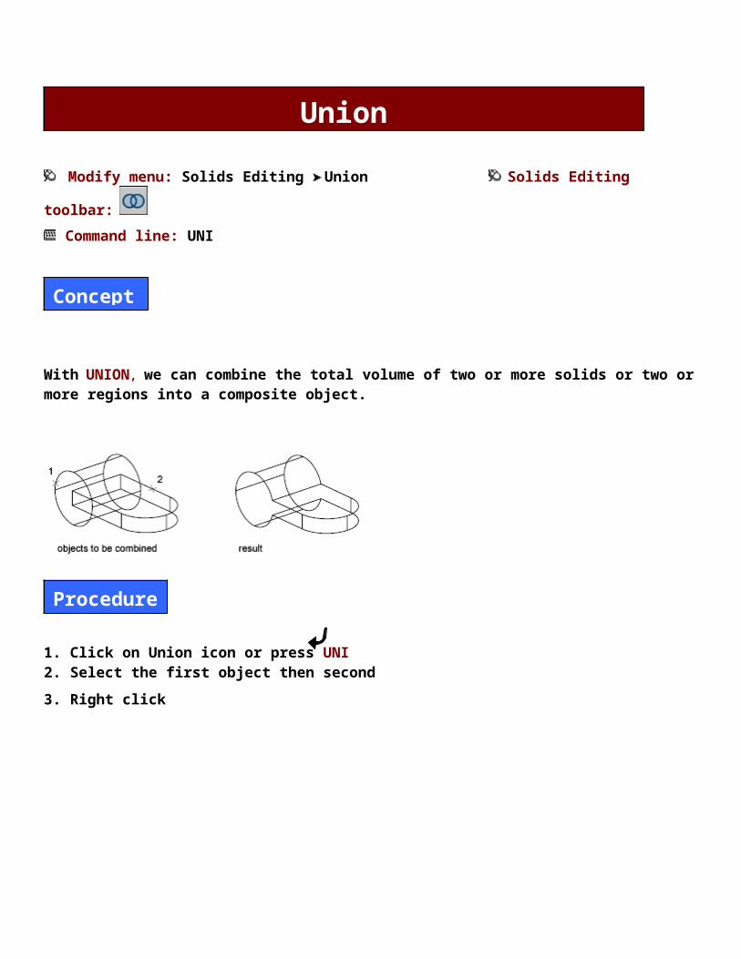
With UNION, we can combine the total volume of two or more solids or two or more regions into a composite object.
1. Click on Union icon or press UNI 2. Select the first object then second
3. Right click
Union
Procedure
Concepts

Modify menu: Solids Editing Subtract Solids Editing toolbar:
Command line: SU
With SUBTRACT, we can remove the common area of one set of solids from another.
1. Click on Subtract icon or press SU 2. Select the outer object 3. Right click4. Select the inner object5. Right click
Subtract
Concepts
Procedure

Modify menu: Solids Editing Intersect Solids Editing toolbar:
Command line: IN
With INTERSECT, we can create a composite solid from the common volume of two or more overlapping solids. INTERSECT removes the non overlapping portions and creates a composite solid from the common volume.
1. Click on Intersect icon or press IN2. Select the objects3. Right click
Intersect
Concepts
Procedure

Modify menu: Solids Editing Extrude Faces Command line: solidedit F E
With EXTRUDE FACES, we can extrude planar faces of a 3D solid along a path or we can specify a height value and a tapered angle
1. Click on Extrude Faces icon or press solidedit F E2. Select the faces3. Right click and click on ENTER4. Specify height of extrusion………….105. Specify angle of taper for extrusion <0>:
Modify menu: Solids Editing Move Faces Command line: solidedit F M
We can edit a 3D solid object by moving selected faces of the object.
1. Click on Move Faces icon or press solidedit F M2. Select the faces3. Right click and click on ENTER4. Specify a base point or displacement5. Specify a second point or displacement
Extrude Faces
Move Faces
Concepts
Procedure
Concepts
Procedure

Modify menu: Solids Editing Offset Faces Command line: solidedit F O
With OFFSET FACES, we can uniformly offset faces by a specified distance.
1. Click on Offset Faces icon or press solidedit F O2. Select the faces3. Right click and click on ENTER4. Specify offset distance
Modify menu: Solids Editing Delete Faces Command line: solidedit F D
With DELETE FACES, we can remove faces and fillets from a 3D solid object.
1. Click on the Delete Faces icon or press solidedit F D2. Select the faces3. Right click and click on ENTER
Offset Faces
Delete Faces
Concepts
Procedure
Concepts
Procedure

Modify menu: Solids Editing Rotate Faces Command line: solidedit F R
With ROTATE FACES, we can rotate selected faces or a collection of features on a 3D solid object.
1. Click on the Rotate Faces icon or press solidedit F R2. Select the faces3. Right click and click on ENTER4. Specify an axis point5. Specify the second point on the rotation axis 6. Specify a rotation angle
Modify menu: Solids Editing Taper Faces Command line: solidedit F T
With TAPER FACES, we can taper selected faces with a draft angle along a vector direction.
Rotate Faces
Taper Faces
Concepts
Procedure
Concepts

1. Click on the Taper Faces icon or press solidedit F T2. Select the faces3. Right click and click on ENTER4. Specify the base point5. Specify another point along the axis of tapering6. Specify the taper angle
Modify menu: Solids Editing Copy Faces Command line: solidedit F C
With COPY FACES, we can copy selected faces on a 3D solid object as separate regions or bodies.
1. Click on Copy Faces icon or press solidedit F C2. Select the faces3. Right click and click on ENTER4. Specify a base point or displacement5. Specify a second point of displacement
Modify menu: Solids Editing Copy Faces Command line: solidedit F COL
With COLOR FACES, we can change the color of a selected face on a 3D solid object.
Procedure
Copy Faces
Concepts
Procedure
Color Faces
Concepts

1. Click on Color Faces icon or press solidedit F COL2. Select the faces3. Right click and click on ENTER4. Select the color5. Click on O.K
Modify menu: Solids Editing Copy Edges Command line: solidedit E C
With COPY EDGES, we can copy individual edges on 3D solid object. All edges are copied as lines, arcs, circles, ellipses, or spines.
1. Click on Copy Edges icon or press solidedit E C2. Select the Edges3. Right click and click on ENTER4. Specify a base point or displacement5. Specify a second point of displacement
Modify menu: Solids Editing Copy Edges Command line: solidedit E COL
Procedure
Copy Edges
Concepts
Procedure
Color Edges

With COLOR EDGES, we can assign colors to individual edges on our 3D solid object. We can select a color from the seven standard colors or select a color from the Select Color dialog box.
1. Click on Color Edges icon or press solidedit E COL2. Select the Edges3. Right click and click on ENTER4. Select the color5. Click on O.K
Modify menu: Solids Editing Imprint
With IMPRINT, we can create new faces on 3D solids by imprinting arcs, circles, lines, 2D and 3D polyline, ellipses, spines, regions, bodies and 3D solids.
1. Click on Imprint icon 2. Select a 3D solid3. Select an object to imprint4. Delete the source object? [Yes / No]: N
Modify menu: Solids Editing Clean
Concepts
Procedure
Imprint
Concepts
Procedure
Clean

1. Click on Clean icon2. Select a 3D solid
Modify menu: Solids Editing Separate
1. Click on Separate icon2. Select a 3D solid
Modify menu: Solids Editing Shell
1. Click on the Shell icon2. Select a 3D solid3. Right click and click on ENTER4. Enter the shell offset distance
Modify menu: Solids Editing Check
Procedure
Separate
Procedure
Shell
Procedure
Check

1. Click on Check icon2. Select a 3D solid
Draw menu: Solids Box Solids toolbar:
Command line: BOX
With BOX, we can create a solid box. The base of the box is always parallel to the XY plane of the current UCS.
1. Click on Box icon or press BOX 2. Specify corner or [cube / Length]: C3. Specify length
Box
Cube
Length
Procedure
Concepts

1. Click on Box icon or press BOX 2. Specify corner or [cube / Length]: L3. Specify length4. Specify width5. Specify height
Draw menu: Solids Sphere Solids toolbar:
Command line: sphere
1. Click on Sphere icon2. Specify the center of sphere3. Specify radius of sphere or [Diameter]: R4. Specify radius
1. Click on Sphere icon2. Specify the center of sphere3. Specify radius of sphere or [Diameter]: D4. Specify diameter
Sphere
Radius
Procedure
Diameter

With CYLINDER , we can create a solid cylinder with a circular or an elliptical base. The base of the cylinder lies on the XY plane of the current UCS.
1. Click on Cylinder icon2. Specify base point for center of cylinder 3. Specify radius for base of cylinder or [Diameter]: R
Cylinder
Radius
Procedure
Concepts

4. Specify radius5. Specify height of cylinder
1. Click on Cylinder icon2. Specify base point for center of cylinder 3. Specify radius for base of cylinder or [Diameter]: D4. Specify Diameter5. Specify height of cylinder
Draw menu: Solids Cone Solids toolbar:
Command line: CONE
With CONE , we can create a solid cone defined by a circular or an elliptical base tapering to a point perpendicular to its base.
Diameter
Cone
Radius
Procedure
Concepts

1. Click on Cone icon2. Specify center point for base of cone3. Specify radius for base of cone or [Diameter]: R4. Specify radius5. Specify height of cone
1. Click on Cone icon2. Specify center point for base of cone3. Specify radius for base of cone or [Diameter]: D4. Specify diameter5. Specify height of cone
Draw menu: Solids Wedge Solids toolbar:
Command line: WE
With WEDGE, we can create a solid wedge. The base of the wedge is parallel to the XY plane of the current UCS with the sloped face opposite the first corner. Its height, which can be positive or negative, is parallel to the Z axis.
Diameter
Wedge
Cube
Procedure
Concepts

1. Click on Wedge icon or press WE2. Specify first corner of wedge3. Specify corner or [Cube/Length]: C4. Specify length
1. Click on Wedge icon or press WE2. Specify first corner of wedge3. Specify corner or [Cube/Length]: L4. Specify length5. Specify width6. Specify height
Draw menu: Solids Torus Solids toolbar:
Command line: TOR
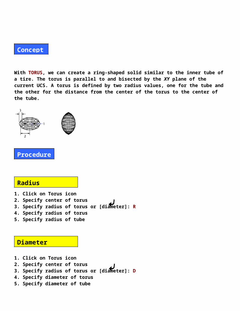
With TORUS, we can create a ring-shaped solid similar to the inner tube of a tire. The torus is parallel to and bisected by the XY plane of the current UCS. A torus is defined by two radius values, one for the tube and the other for the distance from the center of the torus to the center of the tube.
Length
Torus
Procedure
Concepts

1. Click on Torus icon2. Specify center of torus3. Specify radius of torus or [diameter]: R4. Specify radius of torus5. Specify radius of tube
1. Click on Torus icon2. Specify center of torus3. Specify radius of torus or [diameter]: D4. Specify diameter of torus5. Specify diameter of tube
Draw menu: Solids Extrude Solids toolbar:
Command line: EXT
With EXTRUDE, we can create solids by extruding selected objects. We can extrude closed objects such as polylines, polygons, rectangles, circles, ellipses, closed splines, donuts and regions.
Radius
Diameter
Extrude
Concepts

1. Click on Extrude icon or press Ext2. Select objects3. Right click4. Specify height of extrusion or [Path]………..105. Specify angle of taper for extrusion <0>:
Draw menu: Solids Revolve Solids toolbar:
Command line: REV
With REVOLVE, we can create a solid by revolving a closed object about the X or Y axis of the current UCS, using a specified angle. We can also revolve the object about a line, polyline, or two specified points. Similar to EXTRUDE, REVOLVE is useful for objects that contain fillets or other details that would otherwise be difficult to reproduce in a common profile.
Procedure
Revolve
Concepts

1. Click on Revolve icon or press REV2. Select objects3. Right click4. Specify first point of axis5. Specify endpoint point of axis6. Specify angle of revolution <360>:
Draw menu: Solids Slice Solids toolbar:
Command line: SL
With SLICE, we can create a new solid by cutting the existing solid and removing a specified side. We can retain one or both halves of the sliced solids. The sliced solids retain the layer and color properties of the original solids.
Procedure
Slice
Concepts
1. Click on Slice icon or press SL2. Select objects3. Right click4. Specify first point on slicing plane by [Object/Zaxis/View/XY/YZ/ZX/3Points]: 3Points5. Specify second point on plane6. Specify third point on plane7. Specify a point on desired side of the plane
1. Click on Slice icon or press SL2. Select objects3. Right click4. Specify first point on slicing plane by [Object/Zaxis/View/XY/YZ/ZX/3Points]: 3Points5. Specify second point on plane6. Specify third point on plane7. Specify a point on desired side of the plane or [keep Both Sides]: B
Draw menu: Surfaces 2D Solid Surfaces toolbar:
Command line: SO
1. Click on 2D Solid icon2. Specify first point
Procedure
Keep One Side
Keep Both Sides
2D Solid
Procedure

3. Specify second point4. Specify third point5. Specify forth point6. Right click to exit
Draw menu: Surfaces 3D Face Surfaces toolbar:
Command line: 3F
1. Click on 3D Face icon or press 3F2. Specify first point3. Specify second point4. Specify third point5. Specify forth point6. Right click to exit
3D Face
Procedure
Box
Procedure
Cube

1. Click on Box icon2. Specify corner point of box3. Specify length of box4. Specify Width of box or [Cube]: C5. Specify rotation angle of box about Z axis…………30
1. Click on Box icon2. Specify corner point of box3. Specify length of box4. Specify Width of box or [Cube]:5. Specify height of box6. Specify rotation angle of box about Z axis…………30
1. Click on Wedge icon2. Specify corner point of wedge3. Specify length of wedge4. Specify width of wedge5. Specify height of wedge6. Specify rotation angle of wedge about Z axis…………30
1. Click on Pyramid icon
Length
Wedge
Procedure
Pyramid
Procedure

2. Specify first corner point for base of pyramid3. Specify second corner point for base of pyramid4. Specify third corner point for base of pyramid5. Specify forth corner point for base of pyramid6. Specify apex point of pyramid
1. Click on Cone icon2. Specify corner point for base of cone3. Specify radius for base of cone or [Diameter]: R4. Specify radius of cone……55. Specify radius for top of cone <0>:6. Specify height of cone………8 7. Enter number of segments for surface of cone <16>:
1. Click on Cone icon2. Specify corner point for base of cone3. Specify radius for base of cone or [Diameter]: D4. Specify Diameter of cone…55. Specify Diameter for top of cone <0>6. Specify height of cone………8 7. Enter number of segments for surface of cone <16>:
Cone
Radius
Procedure
Diameter
Sphere
Procedure

1. Click on Sphere icon2. Specify center point of sphere3. Specify radius of Sphere or [Diameter]: R4. Specify radius5. Enter number of longitudinal segments for surface of sphere <16>:6. Enter number of latitudinal segments for surface of sphere <16>:
1. Click on Dome icon2. Specify center point of dome3. Specify radius of dome or [Diameter]: R4. Specify radius dome5. Enter number of longitudinal segments for surface of dome <16>:6. Enter number of latitudinal segments for surface of dome <8>:
1. Click on Dome icon2. Specify center point of dome3. Specify radius of dome or [Diameter]: D4. Specify Diameter of dome5. Enter number of longitudinal segments for surface of dome <16>:6. Enter number of latitudinal segments for surface of dome <8>:
Dome
Procedure
Radius
Diameter
Dish

1. Click on Dish icon2. Specify center point of dish3. Specify radius of dish or [Diameter]: R4. Specify radius of dish5. Enter number of longitudinal segments for surface of dish <16>:6. Enter number of latitudinal segments for surface of dish <8>:
1. Click on Dish icon2. Specify center point of dish3. Specify radius of dish or [Diameter]: D4. Specify Diameter of dish5. Enter number of longitudinal segments for surface of dish <16>:6. Enter number of latitudinal segments for surface of dish <8>:
1. Click on Torus icon2. Specify center point of torus3. Specify radius of torus or [Diameter]: R4. Specify radius of torus5. Specify radius of tube6. Enter number of segments around tube circumference <16>:7. Enter number of segments around torus circumference <16>:
1. Click on the Torus icon
Radius
Procedure
Diameter
Torus
Procedure
Radius
Diameter

2. Specify center point of torus3. Specify radius of torus or [Diameter]: D4. Specify diameter of torus5. Specify diameter of tube6. Enter number of segments around tube circumference <16>:7. Enter number of segments around torus circumference <16>:
Modify menu: 3D Operation Array Command line: 3A
1. Click Modify menu Array or press 3A2. Select the object to array 3. Specify Rectangle4. Enter the number of rows5. Enter the number of columns6. Enter the number of levels 7. Specify the distance between rows8. Specify the distance between columns 9. Specify the distance between levels
1. Click Modify menu Array or press 3A2. Select the object to array 3. Specify Polar4. Enter the number of items to array 5. Specify the angle that the arrayed objects are to fill 6. Press Y to rotate the objects or enter N to retain their orientation 7. Specify the start point and endpoint of the axis about which the objects are to be rotate
3D Array
Procedure
Rectangle
Polar