3d convolution on rgb-d point clouds for accurate model ... · resolution of the rgb-d point cloud,...
TRANSCRIPT

3D Convolution on RGB-D Point Clouds forAccurate Model-free Object Pose Estimation
Zhongang Cai Cunjun Yu Quang-Cuong Pham
Abstract—The conventional pose estimation of a 3D object usu-ally requires the knowledge of the 3D model of the object. Evenwith the recent development in convolutional neural networks(CNNs), a 3D model is often necessary in the final estimation.In this paper, we propose a two-stage pipeline that takes in rawcolored point cloud data and estimates an objects translationand rotation by running 3D convolutions on voxels. The pipelineis simple yet highly accurate: translation error is reduced tothe voxel resolution (around 1 cm) and rotation error is around5 degrees. The pipeline is also put to actual robotic graspingtests where it achieves above 90% success rate for test objects.Another innovation is that a motion capture system is usedto automatically label the point cloud samples which makes itpossible to rapidly collect a large amount of highly accurate realdata for training the neural networks.
I. INTRODUCTION
Knowing the position and orientation of a target objectis important for subsequent robotic manipulation tasks. Theconventional approach compares the known model of theobject with the image or point cloud captured to determine itspose. However, an accurate CAD model is often not readilyavailable [1]. Classical algorithms that work on point cloudssuch as principal component analysis (PCA) and iterativeclosest points (ICP) are prone to sensor noises and occlusion.ICP takes exponentially longer time with an increase in thenumber of points to match and it easily gets stuck in a localoptimum if the initial guess is poor.
Neural networks are exceptional in interpreting complexfeatures amidst noises. Hence, we propose a pipeline takes inraw XYZRGB point clouds captured by a RGB-D sensor, andoutput directly the pose estimation including both translationand orientation. 3D convolution on point clouds for pose esti-mation has not been widely applied because of the difficultyof producing accurate labels and the high computation cost.To counter the former, we propose to use a motion capture(MoCap) system for automatic pose labelling; for the latter,we designed the pipeline to have two stages of estimation,allowing for larger and coarser voxels to be used for roughposition estimation and smaller and finer voxels for rotationestimation.
In the first stage, a neural network estimates the translationof the object from the voxels generated from the entire pointcloud that is bounded by the workspace; the second stage takesa closer look at the location where the object is estimated tobe by the previous stage, crop out a sub-cloud, voxelize it with
The authors are with the School of Mechanical and Aerospace Engineering,Nanyang Technological University, Singapore.
Fig. 1. Set-up: a test object is placed on the workbench between the RGB-Dsensor and the robotic arm, and surrounded by MoCap cameras
a finer grid size and pass it to a neural network for rotationestimation.
The main contributions of this paper are:• we validate the proof-of-concept idea of direct pose
estimation using 3D convolution on point clouds. Theexperiments have proved the effectiveness of this methodto achieve high accuracy estimation.
• we present a 3D-2D neural network architecture thatallows networks that are designed for 2D image appli-cations to be directly used for 3D tasks.
• we design a two-stage estimation pipeline that requiressimple neural networks and can run on a less powerfulGPU, yet achieving very high accuracy.
• we propose a new pose labelling method using a MoCapsystem that makes collection and labelling of a large real3D dataset possible. To our knowledge, this is the firstattempt to fully utilizes a MoCap’s flexibility in samplecollection.
II. RELATED WORK
A. Classical Methods
Classical methods towards pose estimation often requiresome prior knowledge of the target object (a CAD modelor a scanned mesh model) and an iterative method has tobe used in order to provide the final estimate. For example,one can register the known 3D CAD model of the object onthe captured image, optimizes the pose estimation throughiteratively minimizing the error of misalignment [2]. Poseestimation using RGB-D sensors have also been explored prior
arX
iv:1
812.
1128
4v1
[cs
.RO
] 2
9 D
ec 2
018

to the prevalent use of deep learning [3]. However, theseclassical methods are limited by the availability of the modelsand achieve relatively low accuracy.
B. Deep Learning on Images
The advent of deep learning has opened up a new possibilityto tackle the pose estimation problem. Some research efforthas been put in pose estimation based on 2D image [4],but bounding box coordinates instead of pose parameters areestimated. [5] performs regression on quaternions, however,without refinement, the error is too large (less than 50% angleestimation has less than 10 degrees) to be useful for roboticmanipulation tasks such as grasping.
C. Deep Learning on Point Clouds
Researchers also take advantage of deep learning’s robust-ness against noisy RGB-D point clouds and apply techniquesin the semantic segmentation as part of the grasping pipeline[6] [7] [8]. However, an object model is required towards theend and classical techniques such as PCA and ICP are stillused for the pose estimation of the object. [5] also uses RGB-D data, but it is only for refinement and ICP is used.
With the advent of autonomous vehicles, for which LiDARsprovide point clouds as an important data input, many haveapplied deep learning in the pose estimation of nearby vehi-cles. [9] We have taken inspirations from these works. Withadditional color information provided by RGB-D sensor and amuch denser point cloud, the pose estimation of our networkis expected to achieve better results.
D. Deep Learning on Graspable Areas
Specific to robotic grasping, deep learning has been appliedto identify the graspable areas [1]. However, it does notprovide pose information of the object. In addition, when thegraspable areas are not visible to the sensor (for example,when the handle is hidden behind the object), the approachdoes not work due to the fact that the neural network is nottrained to understand the object.
E. Other Deep Learning Methods
There are also works to combine autoencoders and CNN[10]. However, only translation estimation is addressed andmanual labelling of real images are required.
III. SET-UP AND CALIBRATION
The workbench is a 1m× 0.5m piece of white rigid board,fixed in front of the robot. Throughout the experiments, we areonly interested in the object that appears on the workbench.Microsoft Kinect Xbox is used as the RGB-D sensor. It isinstalled around 1 m from the workbench and at 45-degreeangle looking down. A Denso robot arm and a Robotiq gripperare used to perform the grapsing.
The MoCap is calibrated follow the official procedure. Wedefine the OptiTrack frame as the base frame, which is setby placing the Ground Plane on the workbench.
For the camera-to-base extrinsic calibration, we use achess pattern with 4 OptiTrack markers pasted on it. The
centroid of the markers intersects the central corner of thepattern. OptiTrack measures the spatial coordinates of the cen-troid in the base frame and the pixel coordinate of the centralcorner is computed by recognizing the pattern captured by theKinect. By moving the pattern around the workspace, multiplecoordinate pairs are collected. We solve the perspective-n-point problem to find the required transformation Tc2b.
For the base-to-robot extrinsic calibration, we have thegripper holding a special calibration device and move througha series of known points in the robot frame. The OptiTrackcaptures corresponding points in the base frame. Manual roughalignment of the two sets of points by setting the 6 extrinsicparameters is followed by iterative closest point (ICP) to refinethe transformation between the two frames. Note that ICP isonly used in the calibration, not in the pose estimation.
IV. DATA COLLECTION AND AUTOMATIC LABELLING
A. MoCap for Accurate Pose Detection
Manual labelling of examples for the training of neural net-works is an extremely laborious procedure. Moreover, accurateobject pose labels are even more difficult to produce due toerrors in measurements.
A common approach towards this is to fix the objects onthe workbench and move the cameras around. This has beenachieved by using fiducial markers [11]. However, a commonset-up in real-life application often involves a fixed cameraand moving targets.
Some researchers have also used motion capture (MoCap)systems for labelling [8], but the objects are still fixed with thecameras moving, which is not essentially different than usingthe fiducial markers.
We propose to fully utilize a MoCap’s capability to providethe pose labels, for it is very accurate (0.2 mm error permarker) and easy to operate with a moving and rotating object.We use 6 OptiTrack 17W cameras to build the MoCap systemas shown in Fig. 1.
B. Test Objects
Four objects are selected for training and testing. Theyare chosen because firstly, they are common domestic ob-jects; secondly, they have irregular geometry, otherwise, poseestimation is less meaningful (a cylinder for example, thegeometry is unchanged when rotating around its longitudinalaxis); thirdly, they have various shapes of handles which areideal for grasping.
For each test object, we have an identical pair of them.One is used for data collection and grasp strategy teaching(referred below as ”marked object”), the other is used solelyfor grasping test (referred below as ”unmarked object”).
OptiTrack markers, which are highly observable to theMoCap cameras, are pasted on the marked object surface. Themarkers used are much smaller to minimize their effect on thecaptured colored point clouds. A very interesting observationis that the markers cannot be detected by the Kinect sensor soit appears to be a void in space. The samples we have collectedcontain many voids amidst colored points due to the limited

Fig. 2. Neural network architecture
resolution of the RGB-D point cloud, the effect of markers onthe learning is mitigated.
C. Data Collection
Not the entire 6-DOF space can be explored by a real objectbecause the object always collapses into few stable poses. Forexample, a mug will not stand on its handle. Therefore, weargue that translation in x and y-axis and rotation about thez-axis are the most important pose parameters and will be thefocus of the experiments. We thus simplify the experiment toonly consider the situation when the object is standing uprighton the workbench. We define the pose with the most prominentgeometrical feature pointing to the positive x-axis direction tohas 0-degree rotation in yaw.
To the best of our ability, we repeatedly place the markedobject at a random location on the workbench with the mostprominent feature pointing at a random direction. As themarked object moves and rotates, synchronized pairs of pointclouds captured by the RGB-D sensor and pose labels by themotion capture system are obtained.
In total, we collected around 1500 examples for the purpledetergent bottle and around 1000 examples for each of the restof the objects.
V. NEURAL NETWORK ARCHITECTURE
A. Architecture
Instead of one network estimating 6 DOF together, wechose to build a two-stage neural network estimation: the firstnetwork takes in a voxelized point cloud with large grid size toestimate the translation of the target object on the workbench.
The estimation is then used to crop a subset of the point cloudand a voxelization with finer grid size is performed on the sub-cloud. The new voxelized point cloud is fed into the secondstage of the neural networks for orientation estimation.
The two-stage architecture has three advantages: the estima-tion of translation and rotation is separated to make trouble-shooting easier; the two stage has to specialize in one taskeach only; most importantly, the two stage can use voxels withdifferent grid sizes, allowing for a faster translation estimationand a more accurate rotation estimation.
It is possible to replace voxelization with new techniquessuch as [12] that work on the unordered point clouds directly.However, we prefer more control over the input and to keepthe simplicity of the architecture for this is a proof-of-concepteffort.
AlexNet is used for 2D images, hence, we topped it witha 3D convolution layer followed by a 3D-2D convolutionlayer for translation estimation. The 3D-2D convolution layerperforms 3D convolution, with the kernel depth dimensionmatching the input’s depth dimension, followed by a dimen-sion squeeze. After this operation, the depth dimension iseliminated, with information in the depth direction encoded.Hence, we can easily apply any 2D CNN backbones to the3D data after this operation.
Although there are more sophisticated CNNs used in the2D image detection realm such as VGG and ResNet, we findout that AlexNet [13], which is a relatively simple network,suffices the task requirements with very high accuracy.
Through experiments, we realized that rotation estimation isa much more challenging task. Hence, the rotation estimation

network is similar to the translation estimation counterpartexcept for an additional 3D convolution layer is added. Thissignificantly improves the performance as more sophisticatedfeature map is needed for correct interpretation of the orienta-tion of the object. In contrast, the translation estimation wherethe network only needs to know where the object is most likelyto be.
Instead of predicting the yaw value in degrees or radians, wedivide one revolution into 72 equal sectors, each representing5 degrees. The rotation estimation network estimates in whichof the sectors is the object oriented. In practice, 5 degrees errorfall well within the tolerance of the gripper. Hence, as longas the rotation estimation network is able to make a correctestimation, it is sufficient for grasping. The starting orientation(yaw = 0 degree) is defined by when the rigid object is firstdefined in the OptiTrack system.
B. Loss Functions
For the translation estimation, the labels are the x, ytranslation values in meters, with respect to the origin of thebase frame. Average L2 Euclidean Loss is used:
Ltrans =1
2N
N∑i=0
(xi − xi)2 + (yi − yi)2
For the rotation estimation, it outputs probability of each ofthe 72 classes, cross-entropy loss is used to treat it as aclassification problem:
Lrotat = −1
N
N∑i=0
71∑j=0
ψij log(ψij)
where ψij is the probability of the jth class of the ith example,it can either be 0 or 1 and
∑j ψij = 1. ψij is the estimated
probability of jth class of the ith example. Note that a softmaxoperation is applied on the output of the fully connected layersof the rotation estimation network to produce ψi.
C. Training
We randomly selected 600 samples from all samples col-lected for each marked object (except for purple detergentbottle, for which 1200 samples are selected) to avoid anyunintentional pattern in the sample collection process withrespect to sampling time. Validation and testing set has size200 samples each. All three sets are exclusive of one another.Adam Optimizer is used in the training, with β1 = 0.9,β2 = 0.999 and ε = 10−8, at a learning rate α = 10−5.Both networks are trained from scratch for 100 epochs and onbatches of size 50.
VI. APPLICATION TO OBJECT GRASPING
It is to note that no object model is used at any stage ofthe pipeline. In fact, no object model is constructed. The onlyinput to the pipeline is the RGB-D point cloud captured by theKinect sensor, and the only prior required is a set of graspingstrategies.
Fig. 3. Pipeline
A. Grasp Strategy Teaching
We first define a grasp strategy as a gripper-to-objecttransformations: Tg2o. Tg2o is used to guide the gripper tothe grasping pose. One or more grasping strategies are taughtfor each object for some objects have multiple graspable areas.
For teaching, a marked object is used, where its pose iscomputed by the MoCap system, from which we obtain To2band its inverse Tb2o. We then guide the gripper to the properpose and record its pose relative to the robot frame provided bythe controller to compute Tg2r. Therefore, the grasp strategyis obtained:
Tg2o = Tg2rTr2bTb2o
where Tr2b is the inverse of base-to-robot calibration Tb2r.In practice, we add an intermediate pose in each grasping
strategy. The gripper is first moved to the intermediate posebefore proceeding to the grasping pose. The procedure tocompute the corresponding transformation matrix is the sameas that for the grasping pose.
B. Pipeline
We construct the pipeline (Fig. 3) to run on ROS. [14] isused to publish the point clouds from the Kinect. The pointcloud subscriber takes in the raw point cloud, transform thepoint cloud into the base frame using the calibrated Tc2b.Through experiments, we found this transformation aids bothestimations. The reason can be that the network has to makeestimations that are in the base frame; having the input in thecamera frame complicates the problem.
The translation voxelizer node takes in the transformedpoint cloud and voxelize a volume of size 100cm × 50cm ×40cm above the workbench into the 100× 50× 40 3D grids,
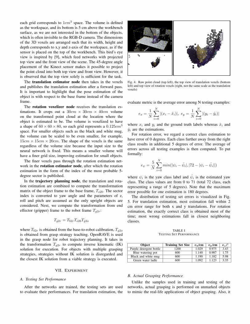
each grid corresponds to 1cm3 space. The volume is definedas the workspace, and its bottom is 5 cm above the workbenchsurface, as we are not interested in the bottom of the objects,which is often invisible to the RGB-D camera. The dimensionsof the 3D voxels are arranged such that its width, height anddepth corresponds to x,y and z-axis of the workspace, as if thesensor is placed on the top of the workbench. This bird’s eyeview is inspired by [9], which feed networks with projectedtop view and the front view of the scene. The 45-degree angleplacement of the Kinect sensor makes it possible to projectthe point cloud into both top view and front view. However, itis observed that the top view solely is sufficient for the task.
The translation estimator node then takes in the voxelsand publishes the translation estimation after a forward pass.It is important to highlight that the pose estimation of theobject is with respect to the base frame instead of the cameraframe.
The rotation voxelizer node receives the translation es-timations. It crops out a 30cm × 30cm × 40cm volumeon the transformed point cloud at the location where theobject is estimated to be. The volume is voxelized to havea shape of 60× 60× 80, so each grid represents a 0.125cm3
space. For smaller objects such as the black and white mug,the volume can be scaled to be even smaller, for example,15cm × 15cm × 20cm. The shape of the voxels is the sameregardless of the volume size because the input size to theneural network is fixed. This means a smaller volume willhave a finer grid size, improving estimation for small objects.
The finer voxels pass through the rotation estimation net-work in the rotation estimator node, after which the rotationestimation in the form of the index of the most probable 5-degree sector is published.
In the trajectory planning node, the translation and rota-tion estimation are combined to compute the transformationmatrix of the object frame to the base frame, To2b. The sectorindex is converted to yaw angle and the parameters of z,roll and pitch are assumed as the only upright objects areconsidered. Next, we compute the transformation from endeffector (gripper) frame to the robot frame Tg2r:
Tg2r = Tb2rTo2bTg2o
where Tb2r is obtained from the base-to-robot calibration, Tg2ois obtained from grasp strategy teaching. OpenRAVE is usedin the grasp node for robot trajectory planning. It takes inthe transformation Tg2r to compute inverse kinematic (IK)solution for execution. For objects with multiple graspingstrategies, strategies without IK solution is disregarded andthe closest IK solution from a viable strategy is executed.
VII. EXPERIMENT
A. Testing Set Performance
After the networks are trained, the testing sets are usedto evaluate their performances. For translation estimation, the
Fig. 4. Raw point cloud (top left), the top view of translation voxels (bottomleft) and top view of rotation voxels (right, not the same scale as the translationvoxels)
evaluate metric is the average error among N testing examples:
ex =1
N
N∑i=0
|(xi − xi)|, ey =1
N
N∑i=0
|(yi − yi)|
where xi and yi and the ground truth labels whereas xi andyi are the estimations.
For rotation error, we regard a correct class estimation tohave error of 0 degrees. Each class further away from the rightclass results in additional 5 degrees of error. The average oferrors across all testing examples is then computed. To putformally:
eψ =5
N
N∑i=0
min(|ψi − ψi|, |72− |ψi − ψi||)
where ψi is the yaw class label and ψi is the estimated yawclass. The class values are from 0 to 71 (total 72 class, eachrepresenting a range of 5 degrees). Note that the maximumerror possible for one estimation is 180 degrees.
The distribution of testing set errors is visualized in Fig.5. For translation estimation, most estimation fall within 2cm error range for both x and y translations. For rotationestimation, the exactly correct class is obtained most of thetime; most wrong estimations fall in closest neighboringclasses.
TABLE ITESTING SET PERFORMANCE
Object Training Set Size ex/cm ey/cm eψ /°Purple detergent bottle 1200 1.029 0.975 3.43
Blue watering pot 600 1.140 0.987 1.75Black and white mug 600 1.190 1.182 5.98
Green water ladle 600 1.092 1.123 3.35
B. Actual Grasping Performance
Unlike the samples used in training and testing of thenetworks, actual grasping is performed on unmarked objectsto mimic the real-life applications of object grasping. Also, it
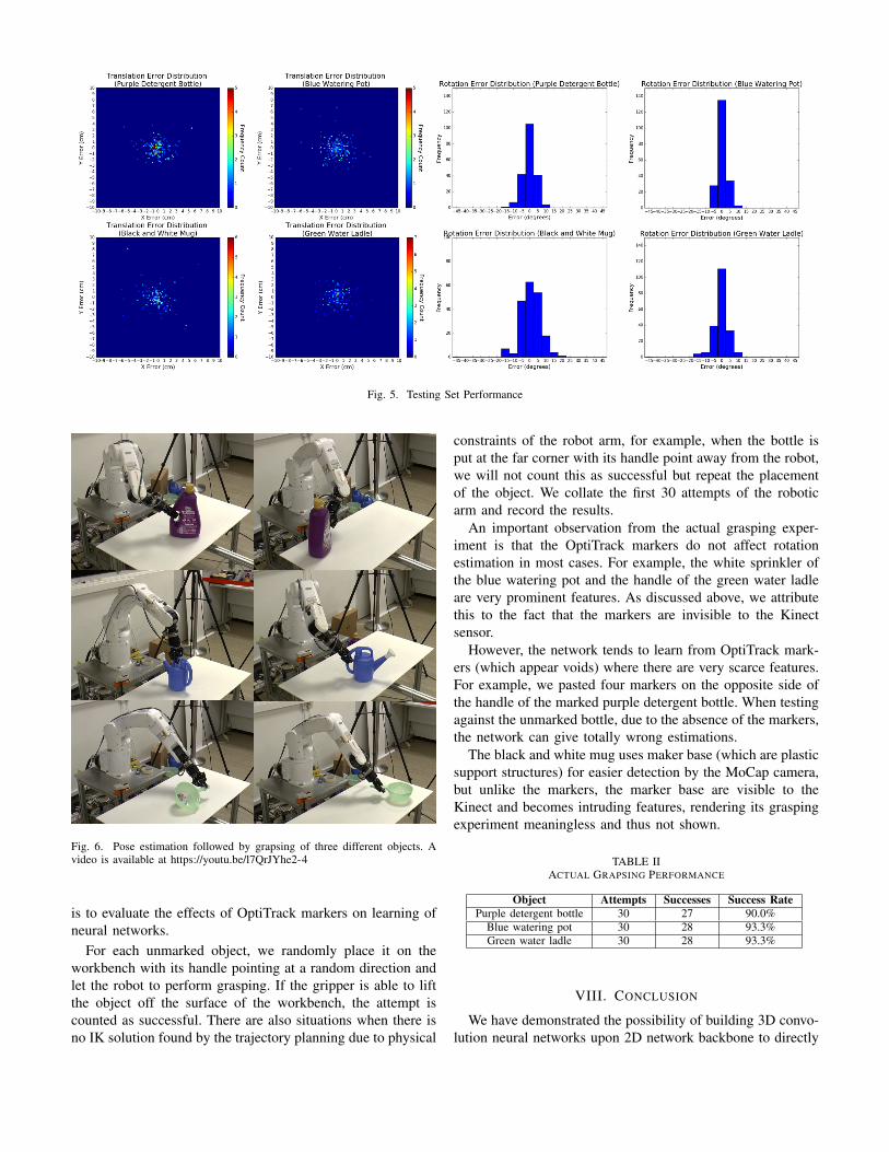
Fig. 5. Testing Set Performance
Fig. 6. Pose estimation followed by grapsing of three different objects. Avideo is available at https://youtu.be/l7QrJYhe2-4
is to evaluate the effects of OptiTrack markers on learning ofneural networks.
For each unmarked object, we randomly place it on theworkbench with its handle pointing at a random direction andlet the robot to perform grasping. If the gripper is able to liftthe object off the surface of the workbench, the attempt iscounted as successful. There are also situations when there isno IK solution found by the trajectory planning due to physical
constraints of the robot arm, for example, when the bottle isput at the far corner with its handle point away from the robot,we will not count this as successful but repeat the placementof the object. We collate the first 30 attempts of the roboticarm and record the results.
An important observation from the actual grasping exper-iment is that the OptiTrack markers do not affect rotationestimation in most cases. For example, the white sprinkler ofthe blue watering pot and the handle of the green water ladleare very prominent features. As discussed above, we attributethis to the fact that the markers are invisible to the Kinectsensor.
However, the network tends to learn from OptiTrack mark-ers (which appear voids) where there are very scarce features.For example, we pasted four markers on the opposite side ofthe handle of the marked purple detergent bottle. When testingagainst the unmarked bottle, due to the absence of the markers,the network can give totally wrong estimations.
The black and white mug uses maker base (which are plasticsupport structures) for easier detection by the MoCap camera,but unlike the markers, the marker base are visible to theKinect and becomes intruding features, rendering its graspingexperiment meaningless and thus not shown.
TABLE IIACTUAL GRAPSING PERFORMANCE
Object Attempts Successes Success RatePurple detergent bottle 30 27 90.0%
Blue watering pot 30 28 93.3%Green water ladle 30 28 93.3%
VIII. CONCLUSION
We have demonstrated the possibility of building 3D convo-lution neural networks upon 2D network backbone to directly

estimate object’s pose. Despite some limitations at the currentstage, using deep learning instead of model-based classicalapproach has shown its potential for highly accurate translationand rotation estimation from a small training set. We have alsoshown that MoCap can be a new alternative to current poselabelling techniques.
IX. ACKNOWLEDGMENT
The authors would like to thank Nanyang TechnologicalUniversity for financial support. We are also grateful towardsFrancisco Surez-Ruiz, Nicholas Adrian, Hung Pham, HuyNguyen and Xu Zhang’s helpful discussion on the set-up.
REFERENCES
[1] A. Saxena, J. Driemeyer, and A. Y. Ng, “Robotic grasping ofnovel objects using vision,” The International Journal of RoboticsResearch, vol. 27, no. 2, pp. 157–173, 2008. [Online]. Available:https://doi.org/10.1177/0278364907087172
[2] S. Jayawardena, D. Yang, and M. Hutter, “3d model assisted imagesegmentation,” in 2011 International Conference on Digital ImageComputing: Techniques and Applications, Dec 2011, pp. 51–58.
[3] C. Choi and H. I. Christensen, “3d pose estimation of daily objectsusing an rgb-d camera,” in 2012 IEEE/RSJ International Conference onIntelligent Robots and Systems, Oct 2012, pp. 3342–3349.
[4] J. Tremblay, T. To, B. Sundaralingam, Y. Xiang, D. Fox, and S. Birch-field, “Deep object pose estimation for semantic robotic grasping ofhousehold objects,” in 2nd Conference on Robot Learning, Zrich,Switzerland, Oct. 2018, pp. 1097–1105.
[5] Y. Xiang, T. Schmidt, V. Narayanan, and D. Fox, “Posecnn: A convolu-tional neural network for 6d object pose estimation in cluttered scenes,”06 2018.
[6] J. Mahler, F. T. Pokorny, B. Hou, M. Roderick, M. Laskey, M. Aubry,K. Kohlhoff, T. Krger, J. Kuffner, and K. Goldberg, “Dex-net 1.0: Acloud-based network of 3d objects for robust grasp planning usinga multi-armed bandit model with correlated rewards,” in 2016 IEEEInternational Conference on Robotics and Automation (ICRA), May2016, pp. 1957–1964.
[7] A. Zeng, K. Yu, S. Song, D. Suo, E. Walker, A. Rodriguez, and J. Xiao,“Multi-view self-supervised deep learning for 6d pose estimation in theamazon picking challenge,” in 2017 IEEE International Conference onRobotics and Automation (ICRA), May 2017, pp. 1386–1383.
[8] J. M. Wong, V. Kee, T. Le, S. Wagner, G. Mariottini, A. Schneider,L. Hamilton, R. Chipalkatty, M. Hebert, D. M. S. Johnson, J. Wu,B. Zhou, and A. Torralba, “Segicp: Integrated deep semantic segmenta-tion and pose estimation,” in 2017 IEEE/RSJ International Conferenceon Intelligent Robots and Systems (IROS), Sept 2017, pp. 5784–5789.
[9] X. Chen, H. Ma, J. Wan, B. Li, and T. Xia, “Multi-view 3d objectdetection network for autonomous driving,” in 2017 IEEE Conferenceon Computer Vision and Pattern Recognition (CVPR), July 2017, pp.6526–6534.
[10] T. Inoue, S. Choudhury, G. D. Magistris, and S. Dasgupta, “Transferlearning from synthetic to real images using variational autoencoders forprecise position detection,” in 2018 25th IEEE International Conferenceon Image Processing (ICIP), Oct 2018, pp. 2725–2729.
[11] E. Brachmann, A. Krull, F. Michel, S. Gumhold, J. Shotton, andC. Rother, “Learning 6d object pose estimation using 3d object coordi-nates,” vol. 8690, 09 2014, pp. 536–551.
[12] R. Q. Charles, H. Su, M. Kaichun, and L. J. Guibas, “Pointnet: Deeplearning on point sets for 3d classification and segmentation,” in 2017IEEE Conference on Computer Vision and Pattern Recognition (CVPR),July 2017, pp. 77–85.
[13] A. Krizhevsky, I. Sutskever, and G. E. Hinton, “Imagenet classificationwith deep convolutional neural networks,” in Advances in NeuralInformation Processing Systems 25, F. Pereira, C. J. C. Burges,L. Bottou, and K. Q. Weinberger, Eds. Curran Associates, Inc.,2012, pp. 1097–1105. [Online]. Available: http://papers.nips.cc/paper/4824-imagenet-classification-with-deep-convolutional-neural-networks.pdf
[14] T. Wiedemeyer, “IAI Kinect2,” https://github.com/code-iai/iai kinect2,Institute for Artificial Intelligence, University Bremen, 2014 – 2015,
accessed June 12, 2015.