3d home architect - design suite deluxe v6.0 - user guide
TRANSCRIPT

383204-MAN
www.broderbund.com
USER’S GUIDE

© 2002-2004 Riverdeep Interactive Learning Limited, and its licensors. © Copyright 1998-2004, Cadsoft Corporation. Helios32 Radiosity Renderer © 1994-2002 Heart Consultants Ltd. Portions of this product were created using LEADTOOLS © 1991-1997 LEAD Technologies, Inc. 3D Studio File Format Library
© 1996-2001 by J.E. Hoffmann [email protected]. This software contains ImageCELs® texture files from
Imagetects. © Copyright 1989-98. ImageCELs® is a registered trademark of IMAGETECTS ™. Portions of content © 2001 Corbis Images. This software contains some symbols from Cad Easy Corporation © Copyright 1991-2004. All rights reserved by their respective parties. Broderbund, 3D Home Architect and 3DTrueView are trademarks or registered trademarks of Riverdeep Interactive Learning Limited. Microsoft and Windows are registered trademarks of Microsoft Corporation in the United States and/or other countries. Pentium is a registered trademark of Intel Corporation in the U.S. and/or other countries. All other trademarks are the property of their respective owners.
The online services advertised as part of this product may be changed or discontinued at any time for any reason.
NOTE: DESIGN PLANS CREATED IN 3D HOME ARCHITECT® OR 3D HOME LANDSCAPE VERSIONS 4 OR EARLIER CANNOT BE IMPORTED INTO THIS PRODUCT.

License Agreement
IMPORTANT: READ CAREFULLY BEFORE USING THIS PRODUCTLICENSE AGREEMENT AND LIMITED WARRANTY
SINGLE-USER PRODUCTSTHIS IS A LEGAL AGREEMENT BETWEEN YOU (EITHER AN INDIVIDUAL OR AN ENTITY) AND RIVERDEEP, INC., AND ITS SUBSIDIARIES AND AFFILIATES ("RIVERDEEP"). THIS AGREEMENT IS GOVERNED BY THE INTERNAL SUBSTANTIVE LAWS OF THE STATE OF MASSACHUSETTS (AND NOT BY THE 1980 UNITED NATIONS CONVENTION ON CONTRACTS FOR THE INTERNATIONAL SALE OF GOODS, AS AMENDED). BY INSTALLING OR USING THE SOFTWARE, YOU AGREE TO BE BOUND BY THE TERMS OF THIS AGREEMENT. IF YOU DO NOT AGREE TO THE TERMS OF THIS AGREEMENT, REMOVE THE PRODUCT FROM YOUR HARD DRIVE AND PERMANENTLY ERASE ALL COPIES OF THE PRODUCT. IF YOU ARE THE ORIGINAL INSTALLER OF THE SOFTWARE YOU MAY PROMPTLY AFTER PURCHASE RETURN THE SOFTWARE (INCLUDING PRINTED MATERIALS) WITH PROOF OF PURCHASE TO THE PLACE WHERE IT WAS PURCHASED FOR A FULL REFUND OF THE AMOUNT PAID.
RIVERDEEP SOFTWARE LICENSEGRANT OF LICENSE. This License Agreement permits you to use one copy of RIVERDEEP software (the "Software"), which may include electronic documentation, on a single computer/workstation. The Software is "in use" on a computer when it is loaded into the temporary memory (i.e., RAM or Cache) or installed into permanent memory (e.g., hard disk, CD-ROM drive, or other storage device) of that computer. This License does not constitute a sale and does not authorize a sale of the Software or anything created thereby. All intellectual property (including copyright, trademark and patent) in the Software, including all animations, audio, images, maps, music, photographs, video, and text incorpo-rated into the Software, are owned by RIVERDEEP and its affiliates, suppliers and licensors, and are protected by United States laws and international treaty provisions. RIVERDEEP and its affiliates, suppliers and licensors retain all rights not expressly granted herein. You must treat the Software like any other copyrighted material, except that you may make one copy of the Software solely for backup or archival purposes. You may transfer your rights under this Agreement on a permanent basis provided you transfer the license granted by this Agreement, and the Software and all associated printed materials, and you retain no copies, and the recipient agrees to all of the terms of this Agreement.
• You may not use the software on or over a network or any other transfer device (including the Internet) except in a manner using the network and online functions included in the Software, if any. Use of the Software on more than one computer constitutes copyright infringement and may be punishable by civil fines, criminal penalties, or both.
• You may not rent or lease the Software, but schools and libraries may lend the Software to third parties provided the Software is in CD format and each end user is given a copy of this License Agreement which will govern the use of such Software.
• You may not modify, translate, reverse engineer, decompile, or disassemble the Software, except to the extent that this restriction is expressly prohibited by applicable law.
• You may not remove any proprietary notices or labels in the Software.
• You may not copy the printed materials accompanying the Software or distribute printed copies of any user documentation provided in electronic format.
• You may not publicly perform or publicly display the Software.

Broderbund®
The restrictions contained herein apply equally to hybrid CD-ROMs which may contain multiple versions of the Software for use on different operating systems. Regardless of the type of media you receive, you may use only the portion appropriate for your single-user computer/workstation. In the event you fail to comply with any of the terms or conditions of this license, your rights to use the Software will end, you shall stop using the Software, remove the Software from your computer, and permanently erase all copies of the Software. You may not export or re-export the Software or any underlying information or technology except in full compliance with all United States and other applicable laws and regulations.
LIMITED WARRANTYLIMITED WARRANTY. RIVERDEEP and its affiliates, suppliers and licensors warrant to the original installer of the Software, for a period of ninety (90) days from the date of purchase, that the media on which the Software is distributed is substantially free from defects in materials and workmanship under normal use. ANY AND ALL OTHER IMPLIED WARRANTIES, STATUTORY OR OTHERWISE, WITH RESPECT TO THE SOFTWARE AND THE ACCOMPANYING WRITTEN MATERIALS, INCLUDING BUT NOT LIMITED TO IMPLIED WARRANTIES OF MERCHANTABILITY, NON-INFRINGEMENT, AND FITNESS FOR A PARTICULAR PURPOSE, ARE HEREBY EXPRESSLY DISCLAIMED.
REMEDIES. Your exclusive remedy shall be, at RIVERDEEP's sole option, (a) the refund of the amount you paid for the Software or (b) repair or replacement of the Software, provided that the defective Software is returned to RIVERDEEP (at Riverdeep, Dock Door #9, 120 Hidden Lake Circle, Duncan, SC 29334. Telephone: (319) 378-7319) along with proof of the date of purchase within ninety (90) days from the date of purchase. This Limited Warranty is void if failure of the Software has resulted from accident, abuse, neglect or misapplication. Any replacement Software will be warranted for the remainder of the original warranty period or thirty (30) days, whichever is longer. Except as set forth above, the Software is sold "as-is", without any express or implied warranties of any kind.
LIMITATION OF LIABILITIES. IN NO EVENT WILL RIVERDEEP OR ITS AFFILIATES, SUPPLIERS AND LICENSORS BE LIABLE FOR ANY INDIRECT, SPECIAL, INCIDENTAL, ECONOMIC, COVER, CONSEQUENTIAL, EXEMPLARY OR PUNITIVE DAMAGES ARISING OUT OF THE USE OF OR INABILITY TO USE THE SOFTWARE, USER DOCUMENTATION, OR RELATED TECHNICAL SUPPORT, INCLUDING, WITHOUT LIMITATION, DAMAGES OR COSTS RELATING TO THE LOSS OF PROFITS, BUSINESS, GOODWILL, DATA, TIME OR COMPUTER PROGRAMS, EVEN IF ADVISED OF THE POSSIBILITY OF SUCH DAMAGES. IN NO EVENT WILL RIVERDEEP'S AND ITS AFFILIATES', SUPPLIERS' AND LICENSORS' LIABILITY EXCEED THE AMOUNT PAID BY YOU FOR THE SOFTWARE REGARDLESS OF THE FORM OF THE CLAIM (INCLUDING, WITHOUT LIMITATION, ANY CONTRACT, PRODUCT LIABILITY, OR TORT CLAIM). BECAUSE SOME JURIS-DICTIONS DO NOT ALLOW THE EXCLUSION OR LIMITATION OF LIABILITY FOR CONSEQUENTIAL OR INCIDENTAL DAMAGES, THE ABOVE LIMITATION MAY NOT APPLY TO YOU.

License Agreement
MISCELLANEOUSRIVERDEEP may cancel, change, modify, discontinue, terminate or charge a fee at any time for any reason for the online services advertised as part of this product.
The links in the Software will allow third-party sites to be accessed. These linked sites are not under thecontrol of RIVERDEEP, and RIVERDEEP is not responsible for the contents of any linked site, and any such inclusion of any link does not imply endorsement by RIVERDEEP of the site.
No change or modification of the License will be valid unless it is in writing and is signed by RIVERDEEP. The provisions of this Agreement are severable; if any provision is held to be invalid or unenforceable, it shall not affect the validity or enforceability of any other provision. If the Software was acquired outside the United States, then local law may apply.
U.S. GOVERNMENT RESTRICTED RIGHTS. The Software and user documentation is provided with RESTRICTED RIGHTS AND LIMITED RIGHTS. Use, duplication, or disclosure by the Government is subject to restrictions as set forth in subparagraph (c)(1)(ii) of the Rights in Technical Data and Computer Software clause at DFARS 252.227-7013 or subparagraphs (c)(1) and (2) of the Commercial Computer Software--Restricted Rights at 48 CFR 52.227-19, as applicable. Riverdeep, Inc., 125 Cambridge Park Drive, Cambridge, MA 02140 U.S.A.


Table of Contents
i
The Basics 1
Chapter 1: Welcome......................................................................................1Package Contents ............................................................................................................................................ 2System Requirements ..................................................................................................................................... 2Important Notes for Previous 3D Home Design Users............................................................................. 2Backing Up Textures from Version 5 ........................................................................................................... 2Uninstalling a Previous Version ................................................................................................................... 3How the Uninstallation Works ..................................................................................................................... 3Installing 3D Home Architect® Design Suite Deluxe 6 ............................................................................ 3Starting the Program ...................................................................................................................................... 4Registering the Program ................................................................................................................................ 4Starting a New Project.................................................................................................................................... 4Using the House Builder Wizard.................................................................................................................. 4Starting a Drawing from Scratch .................................................................................................................. 4Disabling the Startup Dialog......................................................................................................................... 4Adjusting Your Display Settings .................................................................................................................. 4Learning the Program .................................................................................................................................... 5
Program Basics ........................................................................................................................................ 5How to Complete a Project.................................................................................................................... 5How to Use the Tools ............................................................................................................................. 5Advanced Features ................................................................................................................................. 5
Online Help...................................................................................................................................................... 6Troubleshooting Guide .................................................................................................................................. 6Glossary of Terms ........................................................................................................................................... 6Technical Support ........................................................................................................................................... 6
Online Self-Support ................................................................................................................................ 6E-mail Support ........................................................................................................................................ 6Telephone Support ................................................................................................................................. 7
3D Home Architect Online ............................................................................................................................ 7Broderbund.com ............................................................................................................................................. 7
Table of Contents
ii
Table of Contents
Satisfaction Guaranteed ................................................................................................................................. 7
Chapter 2: Screen Layout ............................................................................ 9Title Bar .......................................................................................................................................................... 10Menu Bar ........................................................................................................................................................ 10Toolbars and Toolbar Tabs .......................................................................................................................... 10
Building Toolbar ................................................................................................................................... 10Interiors Toolbar.................................................................................................................................... 10Landscape Toolbar................................................................................................................................ 10Terrain Toolbar...................................................................................................................................... 11Basic View Control Toolbar................................................................................................................. 11Zoom and Navigate Toolbar ............................................................................................................... 11
Catalog Panel ................................................................................................................................................. 11Status Bar........................................................................................................................................................ 12
Chapter 3: House Builder Wizard.............................................................. 13Using the House Builder Wizard................................................................................................................ 14Running the House Builder Wizard When a Drawing is Open............................................................. 16Preventing the House Builder Wizard from Launching ......................................................................... 16
Chapter 4: Building Locations................................................................... 17Defining Building Locations ....................................................................................................................... 18Current Building Location........................................................................................................................... 19Location Dimming ........................................................................................................................................ 19
Chapter 5: Drawing & Editing Basics ....................................................... 21Inserting Elements ........................................................................................................................................ 22Selecting an Insertion Method for Line-Drawn Elements....................................................................... 22Inserting Ceilings Automatically................................................................................................................ 22Going into Selection Mode for Editing ...................................................................................................... 23Disabling Pre-Selection ................................................................................................................................ 23Selecting Elements for Editing .................................................................................................................... 23Deselecting Elements.................................................................................................................................... 24Making Elements on All Locations Selectable in 2D Plan View ............................................................ 24Accessing Edit Tools..................................................................................................................................... 24

Table of Contents
iii
Controlling the View 25
Chapter 6: 2D and 3D Viewing ...................................................................27Viewing the 2D Plan..................................................................................................................................... 28Viewing a 2D Designer’s View ................................................................................................................... 28Viewing in 3D................................................................................................................................................ 29Zooming In and Out..................................................................................................................................... 30Zooming a Selected Area ............................................................................................................................. 30Zooming to Fit the Drawing Area .............................................................................................................. 30Panning Across a Drawing.......................................................................................................................... 30Changing the Display Mode ....................................................................................................................... 30Displaying Framing...................................................................................................................................... 32
Chapter 7: View Filter..................................................................................33Filtering the Display ..................................................................................................................................... 34Displaying/Hiding Building Elements ..................................................................................................... 34Displaying/Hiding Building Locations .................................................................................................... 35Displaying/Hiding Landscape Elements.................................................................................................. 35Displaying/Hiding Text .............................................................................................................................. 36Displaying/Hiding Dimensions................................................................................................................. 36Displaying/Hiding Electrical Wiring ........................................................................................................ 36Displaying/Hiding Project Trace Images ................................................................................................. 37Selection Filtering.......................................................................................................................................... 37Making Building Elements Selectable or Non-Selectable ....................................................................... 38Making Building Locations Selectable or Non-Selectable ...................................................................... 38Making Landscape Elements Selectable or Non-Selectable.................................................................... 39Making Text Selectable or Non-Selectable ................................................................................................ 39Making Dimensions Selectable or Non-Selectable................................................................................... 40Making Electrical Wiring Selectable or Non-Selectable .......................................................................... 40Making Project Trace Images Selectable or Non-Selectable ................................................................... 40
Building Your Home 41
Chapter 8: Foundation................................................................................43Creating a Basement or Crawlspace Foundation..................................................................................... 44Editing a Wall’s Height, Width or Elevation ............................................................................................ 45Lengthening and Shortening Walls............................................................................................................ 45Rotating a Wall .............................................................................................................................................. 45

iv
Table of Contents
Curving a Wall .............................................................................................................................................. 46Breaking a Wall ............................................................................................................................................. 46Deleting a Wall .............................................................................................................................................. 46Applying a Different Material to the Foundation Floor.......................................................................... 46Inserting Strip Footings Beneath the Foundation Walls ......................................................................... 47Editing the Strip Footing Type.................................................................................................................... 47Editing the Size of Strip Footings ............................................................................................................... 47Moving/Stretching Strip Footings ............................................................................................................. 47Lengthening and Shortening Strip Footings............................................................................................. 48Breaking Strip Footings................................................................................................................................ 48Deleting Strip Footings ................................................................................................................................ 48Inserting Columns ........................................................................................................................................ 48Editing the Column Type ............................................................................................................................ 49Editing the Size and Elevation of a Column ............................................................................................. 49Moving Columns .......................................................................................................................................... 49Deleting a Column........................................................................................................................................ 49Inserting Mono Footings Under Columns ................................................................................................ 49Editing the Mono Footing Type.................................................................................................................. 50Editing the Size of Mono Footings ............................................................................................................. 50Moving Mono Footings................................................................................................................................ 50Rotating a Mono Footing ............................................................................................................................. 50Deleting Mono Footings............................................................................................................................... 50Creating a Slab Foundation ......................................................................................................................... 51Moving a Slab ................................................................................................................................................ 51Resizing a Slab............................................................................................................................................... 51Reshaping a Slab ........................................................................................................................................... 51Rotating a Slab............................................................................................................................................... 52Editing the Thickness of a Slab ................................................................................................................... 52Deleting a Slab............................................................................................................................................... 52
Chapter 9: Walls.......................................................................................... 53Drawing the Ground Floor Exterior Walls................................................................................................ 54Adding a Story .............................................................................................................................................. 55Applying Different Finishes to Exterior Walls ......................................................................................... 56Drawing Interior Walls ................................................................................................................................ 57Editing a Wall’s Height, Width or Elevation ............................................................................................ 57Lengthening and Shortening Walls............................................................................................................ 57Rotating a Wall .............................................................................................................................................. 57Curving a Wall .............................................................................................................................................. 58Breaking a Wall ............................................................................................................................................. 58Deleting a Wall .............................................................................................................................................. 58Adding Paint and Wallpaper ...................................................................................................................... 58

Table of Contents
v
Adding Trim to Walls .................................................................................................................................. 59
Chapter 10: Doors, Windows & Openings ................................................61Inserting Doors.............................................................................................................................................. 62Editing Door Types....................................................................................................................................... 62Editing the Size and Shape of a Door......................................................................................................... 62Editing a Door’s Sidelites and Highlites.................................................................................................... 63Editing a Door Leaf....................................................................................................................................... 64Editing Door Details ..................................................................................................................................... 64Flipping a Door ............................................................................................................................................. 65Flipping a Door Swing ................................................................................................................................. 65Moving a Door .............................................................................................................................................. 65Raising or Lowering a Door ........................................................................................................................ 66Deleting a Door ............................................................................................................................................. 66Inserting Windows ....................................................................................................................................... 66Editing Window Types ................................................................................................................................ 67Editing a Window’s Size Properties........................................................................................................... 67Editing a Window’s Sidelites, Highlites and Lowlites ............................................................................ 68Editing Window Details............................................................................................................................... 69Flipping a Window....................................................................................................................................... 70Moving a Window ........................................................................................................................................ 70Raising or Lowering a Window.................................................................................................................. 70Deleting a Window....................................................................................................................................... 70Inserting Wall Openings .............................................................................................................................. 70Editing the Shape of a Wall Opening......................................................................................................... 71Editing the Size of a Wall Opening ............................................................................................................ 71Moving a Wall Opening............................................................................................................................... 71Raising or Lowering a Wall Opening ........................................................................................................ 72Deleting a Wall Opening.............................................................................................................................. 72
Chapter 11: Floors & Ceilings....................................................................73How Floors are Created ............................................................................................................................... 74Defining Individual Floor Areas................................................................................................................. 74Raising or Lowering a Floor ........................................................................................................................ 74Editing the Thickness of a Floor ................................................................................................................. 75Applying Different Materials to Floors ..................................................................................................... 75Inserting Openings in Floors....................................................................................................................... 75Deleting a Floor ............................................................................................................................................. 75How Ceilings Are Created........................................................................................................................... 75Inserting Ceilings by Perimeter .................................................................................................................. 76Inserting Ceilings by Room ......................................................................................................................... 76

vi
Table of Contents
Inserting a Ceiling by Picking Points ......................................................................................................... 77Raising or Lowering a Ceiling .................................................................................................................... 77Curving a Ceiling Edge................................................................................................................................ 77Inserting Openings in Automatic Ceilings................................................................................................ 78Inserting Openings in Manually Inserted Ceilings.................................................................................. 78Resizing a Ceiling Opening ......................................................................................................................... 78Curving a Ceiling Opening Edge ............................................................................................................... 79Removing Ceiling Openings ....................................................................................................................... 79Applying Different Colors and Materials to Ceilings ............................................................................. 79Deleting a Ceiling.......................................................................................................................................... 80
Chapter 12: Stairs, Ramps & Railings ...................................................... 81Inserting Stairs and Ramps.......................................................................................................................... 82Parts of a Staircase ........................................................................................................................................ 82Editing Stair Size Properties ........................................................................................................................ 82Editing a Staircase Layout ........................................................................................................................... 83Editing Stair Details ...................................................................................................................................... 84Editing the Appearance of the Cut Line.................................................................................................... 85Editing General Ramp Properties............................................................................................................... 85Editing the Layout of a Ramp ..................................................................................................................... 86Moving a Staircase or Ramp........................................................................................................................ 87Rotating a Staircase or Ramp ...................................................................................................................... 87Deleting a Staircase or Ramp ...................................................................................................................... 87Inserting Railings on Staircases and Ramps ............................................................................................. 87Inserting a Horizontal Railing..................................................................................................................... 89Parts of a Railing ........................................................................................................................................... 89Editing Railing Properties............................................................................................................................ 89Stretching a Railing....................................................................................................................................... 91Rotating a Railing.......................................................................................................................................... 91Deleting Railings ........................................................................................................................................... 91
Chapter 13: Roofs....................................................................................... 93Inserting an Automatic Roof Over Perimeter Walls................................................................................ 94Inserting a Roof by Picking Points ............................................................................................................. 94Changing the Way a Lower-story Roof is Created .................................................................................. 95Converting a Hip Roof to a Gable Roof..................................................................................................... 96Changing the Appearance of Raked Surfaces Under Gable Ends......................................................... 96Extending Walls Beneath Gable Ends........................................................................................................ 97Creating a Porch Roof .................................................................................................................................. 97Selecting a Roof for Editing ......................................................................................................................... 99Stretching a Roof ........................................................................................................................................... 99

Table of Contents
vii
Moving a Roof ............................................................................................................................................... 99Rotating a Roof............................................................................................................................................ 100Editing a Roof’s Shape and Size................................................................................................................ 100Editing the Height of a Roof...................................................................................................................... 101Editing a Roof’s Frame Details.................................................................................................................. 101Applying a Different Roofing Material ................................................................................................... 101Cutting an Opening in a Roof ................................................................................................................... 102Removing Roof Openings.......................................................................................................................... 102Deleting a Roof ............................................................................................................................................ 102Inserting Dormers ....................................................................................................................................... 102Moving a Dormer Roof .............................................................................................................................. 103Stretching a Dormer Roof .......................................................................................................................... 104Deleting a Dormer ...................................................................................................................................... 104Inserting Skylights ...................................................................................................................................... 104Moving a Skylight....................................................................................................................................... 104Rotating a Skylight...................................................................................................................................... 104Editing the Properties of a Skylight ......................................................................................................... 105Deleting a Skylight...................................................................................................................................... 105
Designing the Interior 107
Chapter 14: Kitchen Builder Wizard ........................................................109Creating a Kitchen with the Kitchen Builder Wizard............................................................................ 110
Chapter 15: Cabinets ................................................................................113Inserting Cabinets ....................................................................................................................................... 114Moving Cabinets ......................................................................................................................................... 114Rotating Cabinets........................................................................................................................................ 114Raising or Lowering a Cabinet.................................................................................................................. 114Editing Cabinet Properties ........................................................................................................................ 114Applying Different Finishes to Cabinets ................................................................................................. 116Inserting a Sink into a Cabinet .................................................................................................................. 116Deleting a Cabinet....................................................................................................................................... 116
Chapter 16: Appliances ............................................................................117Inserting Appliances................................................................................................................................... 118Moving Appliances..................................................................................................................................... 118Rotating Appliances ................................................................................................................................... 118Raising or Lowering an Appliance........................................................................................................... 118

viii
Table of Contents
Editing Appliance Size Properties............................................................................................................ 118Applying a Different Color or Finish to Appliances ............................................................................. 119Deleting an Appliance................................................................................................................................ 119
Chapter 17: Furniture, Electronics & Accessories ................................ 121Inserting Furniture...................................................................................................................................... 122Inserting Electronics ................................................................................................................................... 122Inserting Accessories .................................................................................................................................. 122Moving Furnishing Elements.................................................................................................................... 122Rotating Furnishing Elements................................................................................................................... 122Raising or Lowering a Furnishing Element ............................................................................................ 123Editing the Size of Furnishing Elements ................................................................................................. 123Applying Different Colors, Fabrics and Finishes to Furnishing Elements......................................... 123Deleting Furnishing Elements................................................................................................................... 124
Utilities 125
Chapter 18: Interior Lighting ................................................................... 127Inserting Interior Light Fixtures ............................................................................................................... 128Changing the Way a Light Snaps on Insertion....................................................................................... 128Raising or Lowering a Light Fixture ........................................................................................................ 128Moving Light Fixtures................................................................................................................................ 128Rotating Light Fixtures .............................................................................................................................. 129Editing the Size of Light Fixtures ............................................................................................................. 129Editing a Light Fixture’s Light Source ..................................................................................................... 129Turning a Light On or Off ......................................................................................................................... 130Changing the Look of a Light Fixture...................................................................................................... 130Deleting Light Fixtures............................................................................................................................... 131
Chapter 19: Electrical ............................................................................... 133Inserting Outlets and Switches ................................................................................................................. 134Inserting Thermostats and Smoke Detectors .......................................................................................... 134Raising or Lowering an Electrical Element ............................................................................................. 134Moving an Electrical Element ................................................................................................................... 135Editing the Size of an Electrical Element ................................................................................................. 135Applying a Different Color or Material to an Electrical Element ........................................................ 135Deleting Electrical Elements...................................................................................................................... 135Inserting Wiring .......................................................................................................................................... 136Stretching and Reshaping Wiring Segments .......................................................................................... 136

Table of Contents
ix
Changing the Line Style of Wiring........................................................................................................... 136Deleting Wiring........................................................................................................................................... 137
Chapter 20: Plumbing ...............................................................................139Inserting Plumbing Fixtures...................................................................................................................... 140Raising or Lowering a Plumbing Fixture ................................................................................................ 140Moving Plumbing Fixtures........................................................................................................................ 140Rotating Plumbing Fixtures ...................................................................................................................... 140Editing the Size of a Plumbing Fixture .................................................................................................... 140Applying a Different Color or Finish to Plumbing Fixtures................................................................. 141Deleting Plumbing Fixtures....................................................................................................................... 141
Chapter 21: Heating & Ventilation ...........................................................143Inserting Heating Elements ....................................................................................................................... 144Inserting Floor Registers and Cold Air Returns..................................................................................... 144Inserting a Chimney ................................................................................................................................... 144Moving HVAC Elements ........................................................................................................................... 145Rotating HVAC Elements.......................................................................................................................... 145Raising or Lowering an HVAC Element ................................................................................................. 145Editing the Size of an HVAC Element ..................................................................................................... 145Deleting HVAC Elements.......................................................................................................................... 145
Terrain Modeling 147
Chapter 22: Terrain Modeling...................................................................149Defining the Basic Terrain ......................................................................................................................... 150Creating Hills and Valleys......................................................................................................................... 150Creating Berms and Trenches ................................................................................................................... 151Creating Plateaus ........................................................................................................................................ 152Creating Slopes............................................................................................................................................ 153Turning the Terrain On and Off ............................................................................................................... 155
Chapter 23: Property Lines ......................................................................157Defining Your Building Lot....................................................................................................................... 158Defining a Custom Building Lot............................................................................................................... 159

x
Table of Contents
Working on the Exterior of Your Home 161
Chapter 24: Fences & Gates.................................................................... 163Inserting a Fence ......................................................................................................................................... 164Stretching a Fence Layout.......................................................................................................................... 165Changing the Length of a Fence ............................................................................................................... 165Creating a Break in a Fence ....................................................................................................................... 165Parts of a Fence............................................................................................................................................ 165Editing the Properties of a Fence .............................................................................................................. 165Changing the Fencing Material................................................................................................................. 167Deleting a Fence .......................................................................................................................................... 167Inserting a Gate ........................................................................................................................................... 167Moving a Gate ............................................................................................................................................. 168Flipping a Gate ............................................................................................................................................ 168Flipping a Gate’s Swing ............................................................................................................................. 168Editing the Properties of a Gate................................................................................................................ 168Deleting a Gate ............................................................................................................................................ 169
Chapter 25: Decks & Patios..................................................................... 171Using the Deck Builder Wizard ................................................................................................................ 172Building a Deck with the Deck Tool ........................................................................................................ 173Moving a Deck............................................................................................................................................. 174Rotating a Deck ........................................................................................................................................... 174Changing the Direction of Deck Boards .................................................................................................. 174Stretching a Deck ........................................................................................................................................ 174Reshaping a Deck........................................................................................................................................ 174Curving a Deck Edge.................................................................................................................................. 174Changing the Height of a Deck................................................................................................................. 175Editing Deck Post Properties..................................................................................................................... 175Displaying Footings Under Deck Posts ................................................................................................... 175Editing the Deck Frame.............................................................................................................................. 175Changing the Railing Style ........................................................................................................................ 176Controlling the Display of Deck Railings................................................................................................ 177Controlling the Display of Deck Skirting ................................................................................................ 177Inserting Openings in a Deck.................................................................................................................... 177Resizing a Deck Opening........................................................................................................................... 178Reshaping a Deck Opening ....................................................................................................................... 178Curving a Deck Opening Edge ................................................................................................................. 178Removing Deck Openings ......................................................................................................................... 178Deleting a Deck ........................................................................................................................................... 178

Table of Contents
xi
Adding Stairs to a Deck ............................................................................................................................. 178Moving Deck Stairs..................................................................................................................................... 179Parts of a Staircase ...................................................................................................................................... 179Editing the Size of Deck Stairs .................................................................................................................. 179Controlling the Display of Railings on Deck Stairs ............................................................................... 180Editing Stringers, Risers and Treads........................................................................................................ 180Deleting Deck Stairs ................................................................................................................................... 181Creating a Patio ........................................................................................................................................... 181Moving a Patio Slab .................................................................................................................................... 182Resizing a Patio Slab................................................................................................................................... 182Reshaping a Patio Slab ............................................................................................................................... 182Rotating a Patio Slab................................................................................................................................... 182Editing the Thickness of a Patio Slab ....................................................................................................... 183Apply a Different Material to a Patio....................................................................................................... 183Deleting a Patio Slab................................................................................................................................... 183
Chapter 26: Retaining Walls.....................................................................185Drawing Retaining Walls........................................................................................................................... 186Editing a Retaining Wall’s Height, Width or Elevation ........................................................................ 186Lengthening and Shortening Retaining Walls........................................................................................ 186Rotating a Retaining Wall.......................................................................................................................... 186Curving a Retaining Wall .......................................................................................................................... 186Breaking a Retaining Wall ......................................................................................................................... 187Applying Different Finishes to Retaining Walls .................................................................................... 187Deleting a Retaining Wall .......................................................................................................................... 187
Chapter 27: Sidewalks, Pathways & Driveways...............................................................................................189
Drawing Sidewalks, Pathways and Driveways ..................................................................................... 190Stretching a Path Element.......................................................................................................................... 190Moving a Path Element.............................................................................................................................. 191Editing the Thickness or Width of a Path Element ................................................................................ 191Applying Different Materials to Path Elements ..................................................................................... 191Deleting a Path Element............................................................................................................................. 191
Landscaping 193
Chapter 28: Garden Beds, Ponds & Other Filled Areas.........................195Creating Filled Areas.................................................................................................................................. 196

xii
Table of Contents
Resizing a Filled Area................................................................................................................................. 196Reshaping a Filled Area ............................................................................................................................. 196Rotating a Filled Area................................................................................................................................. 197Moving a Filled Area.................................................................................................................................. 197Changing the Fill Material......................................................................................................................... 197Deleting a Filled Area................................................................................................................................. 197
Chapter 29: Edging................................................................................... 199Inserting Edging.......................................................................................................................................... 200Cleaning Up Corners.................................................................................................................................. 200Changing the Length of Edging................................................................................................................ 201Breaking Edging.......................................................................................................................................... 201Moving Edging............................................................................................................................................ 201Rotating Edging .......................................................................................................................................... 201Editing the Height or Width of Edging ................................................................................................... 202Changing the Edging Material.................................................................................................................. 202Deleting Edging........................................................................................................................................... 202
Chapter 30: Trees, Shrubs & Plants........................................................ 203Inserting Plants............................................................................................................................................ 204Moving a Plant ............................................................................................................................................ 204Changing the Elevation of a Plant ............................................................................................................ 204Editing the 2D Appearance of a Plant...................................................................................................... 204Changing the Age of a Plant...................................................................................................................... 205Forcing a Custom Plant Size...................................................................................................................... 205Deleting a Plant ........................................................................................................................................... 206Seeing Plant Growth Over Time............................................................................................................... 206Applying Seasonal Changes to Plants ..................................................................................................... 206Using the Plant Encyclopedia ................................................................................................................... 207The Encyclopedia Main Page .................................................................................................................... 208
Selecting a Plant to View.................................................................................................................... 208Viewing Plant Information................................................................................................................ 208Plant Views .......................................................................................................................................... 209
Plant Care Calendar.................................................................................................................................... 210World Map Page ......................................................................................................................................... 212Notebook Page ............................................................................................................................................ 213Picture Page ................................................................................................................................................. 214Diseases Page............................................................................................................................................... 215Filtering the Plant List ................................................................................................................................ 216Adding a Plant from the Encyclopedia to the Catalog.......................................................................... 217

Table of Contents
xiii
Chapter 31: Exterior Furniture .................................................................219Inserting Exterior Furniture ...................................................................................................................... 220Moving Exterior Furniture ........................................................................................................................ 220Rotating Exterior Furniture ....................................................................................................................... 220Editing the Size of Exterior Furniture ...................................................................................................... 220Applying Different Colors or Finishes to Exterior Furniture............................................................... 220Deleting Exterior Furniture ....................................................................................................................... 221
Chapter 32: Exterior Structures...............................................................223Inserting Exterior Structures ..................................................................................................................... 224A Note About House Templates .............................................................................................................. 224Moving Exterior Structures ....................................................................................................................... 224Rotating Exterior Structures ...................................................................................................................... 224Editing the Size of an Exterior Structure ................................................................................................. 225Applying Different Colors or Materials to Exterior Structures............................................................ 225Deleting an Exterior Structure .................................................................................................................. 225
Chapter 33: Landscape Lighting..............................................................227Inserting Landscape Lighting ................................................................................................................... 228Moving a Landscape Light Fixture .......................................................................................................... 228Editing the Size of a Landscape Light Fixture ........................................................................................ 228Editing a Light Fixture’s Light Source ..................................................................................................... 228Turning a Light On or Off ......................................................................................................................... 229Changing the Look of a Landscape Light Fixture.................................................................................. 230Deleting a Landscape Light Fixture ......................................................................................................... 230
Chapter 34: Exterior Accessories............................................................231Inserting Exterior Accessories................................................................................................................... 232Moving Exterior Accessories..................................................................................................................... 232Rotating Exterior Accessories.................................................................................................................... 232Raising or Lowering an Exterior Accessory............................................................................................ 232Editing the Size of an Exterior Accessory................................................................................................ 232Changing the Look of an Exterior Accessory ......................................................................................... 233Deleting an Exterior Accessory................................................................................................................. 233
Chapter 35: Irrigation................................................................................235Inserting Irrigation...................................................................................................................................... 236Moving Sprinklers ...................................................................................................................................... 236Rotating Sprinklers ..................................................................................................................................... 236Editing the Height of a Sprinkler.............................................................................................................. 236

xiv
Table of Contents
Editing a Sprinkler’s Spray Coverage...................................................................................................... 236Deleting a Sprinkler.................................................................................................................................... 236
Drawing & Editing Tools 237
Chapter 36: Drawing Aids........................................................................ 239Setting Up a Drawing Grid........................................................................................................................ 240Turning the Drawing Grid On and Off ................................................................................................... 240Using the Grid Snap ................................................................................................................................... 240Turning the Grid Snap On and Off .......................................................................................................... 240Using the Object Snap ................................................................................................................................ 240Using Ortho ................................................................................................................................................. 241Using Angle Snap ....................................................................................................................................... 241Disabling/Enabling Collision Control..................................................................................................... 241
Chapter 37: Measurement........................................................................ 243Changing the Unit of Measure.................................................................................................................. 244Suppressing Metric Units in Dialogs ....................................................................................................... 244Measuring Distances .................................................................................................................................. 244Measuring Area and Perimeter................................................................................................................. 245
Chapter 38: Commander .......................................................................... 247Displaying the Commander ...................................................................................................................... 248Using the Commander ............................................................................................................................... 248Displaying the Coordinate Icon................................................................................................................ 248Specifying the Insertion Height of an Element Before You Insert It ................................................... 248Selecting a Reference Point When Inserting and Editing Elements .................................................... 249Entering Values in the Commander......................................................................................................... 249Direction and Angle of Rotation............................................................................................................... 250Defining Points in the Cartesian Coordinate System ............................................................................ 250Specifying Distance and Direction in the Polar Coordinate System ................................................... 250Using the Commander When Rotating Elements .................................................................................. 250Using the Commander When Curving Elements .................................................................................. 251
Chapter 39: Editing Your Design............................................................. 253Undoing the Previous Action.................................................................................................................... 254Redoing an Undo ........................................................................................................................................ 254Accessing Edit Commands........................................................................................................................ 254Moving Elements ........................................................................................................................................ 254

Table of Contents
xv
Doing a Straight Drag-and-Drop...................................................................................................... 254Using the Move Tool .......................................................................................................................... 254
Raising or Lowering an Element .............................................................................................................. 255Rotating Elements in 2D Plan View ......................................................................................................... 255
Doing a Simple, On-the-Spot Rotation ............................................................................................ 255Using the Rotate Tool ......................................................................................................................... 256
Changing an Element’s Orientation......................................................................................................... 256Copying Elements on the Same Location................................................................................................ 257Copying Elements to Other Locations ..................................................................................................... 257Arraying Elements ...................................................................................................................................... 257Deleting Elements ....................................................................................................................................... 258Editing the Size and Composition of an Element .................................................................................. 258Changing an Element’s Material or Color............................................................................................... 259
Power Tools 261
Chapter 40: Project Trace Image .............................................................263Importing an Image to Trace..................................................................................................................... 264Matching the Floor Plan’s Drawing Scale ............................................................................................... 264Tracing the Imported Floor Plan .............................................................................................................. 264Deleting a Project Trace Image ................................................................................................................. 265
Chapter 41: Photo Boards........................................................................267Importing a Photo Board ........................................................................................................................... 268Adding an Imported Photo Board to Your Catalog............................................................................... 269Inserting a Photo Board from the Catalog............................................................................................... 269Moving a Photo Board ............................................................................................................................... 269Rotating a Photo Board in 2D Plan View ................................................................................................ 269Changing the Elevation of a Photo Board ............................................................................................... 270Changing a Photo Board from Stationary to Rotating and Vice Versa............................................... 270Editing the Size of a Photo Board ............................................................................................................. 270Deleting a Photo Board .............................................................................................................................. 270Creating Transparency in Photo Board Images...................................................................................... 270
Chapter 42: Text & Dimensions ...............................................................273Adding Text to Your Drawing.................................................................................................................. 274Moving Text................................................................................................................................................. 274Rotating Text................................................................................................................................................ 274Editing Text Content .................................................................................................................................. 274

xvi
Table of Contents
Changing the Style of Text......................................................................................................................... 275Changing the Justification of Multi-line Text ......................................................................................... 275Deleting Text................................................................................................................................................ 275Adding Text with a Leader........................................................................................................................ 275Moving and Stretching a Leader .............................................................................................................. 276Changing the Leader Arrow Style............................................................................................................ 276Moving Leader Text ................................................................................................................................... 277Editing Leader Text .................................................................................................................................... 277Deleting Text with a Leader ...................................................................................................................... 277Dimensioning .............................................................................................................................................. 277Setting the Current Dimension Style........................................................................................................ 277Creating Automatic Exterior Dimensions ............................................................................................... 278Specifying Exterior Dimension Settings .................................................................................................. 278Creating Auto Interior Dimensions.......................................................................................................... 279Specifying Interior Dimension Settings ................................................................................................... 280Creating Linear Dimensions...................................................................................................................... 280Creating Aligned Dimensions................................................................................................................... 281Moving a Dimension Line ......................................................................................................................... 281Stretching Dimensions ............................................................................................................................... 281Changing the Style of a Dimension.......................................................................................................... 282Deleting a Dimension................................................................................................................................. 282Dimension Style Properties ....................................................................................................................... 282
Anatomy of a Dimension................................................................................................................... 282Lines and Arrows................................................................................................................................ 282Dimension Text ................................................................................................................................... 283Line Styles ............................................................................................................................................ 283
Chapter 43: Project Estimate................................................................... 285Generating a Project Estimate ................................................................................................................... 286Opening a Saved Estimate......................................................................................................................... 287Editing Material Pricing............................................................................................................................. 287
Chapter 44: 3DTrueView™....................................................................... 289How 3DTrueView™ Rendering Works................................................................................................... 290Setting the Viewpoint for the Scene ......................................................................................................... 290Setting the Scene.......................................................................................................................................... 290Defining Your Location and Time of Day ............................................................................................... 291Creating a 3DTrueView™ Rendering...................................................................................................... 292Adjusting the Rendering Quality ............................................................................................................. 293Changing the Refresh Rate During Lighting Calculations ................................................................... 293Adjusting the Brightness of the Rendered Image .................................................................................. 293

Table of Contents
xvii
Turning Daylight Off.................................................................................................................................. 294Using Antialiasing to Reduce Jagged Edges........................................................................................... 294Creating a Fog Effect .................................................................................................................................. 294Creating a Smoke Effect ............................................................................................................................. 294Adjusting the Light Coming from Light Fixtures .................................................................................. 295Editing the Surface Properties of Materials ............................................................................................ 295Saving a 3DTrueView™ Rendering to a File .......................................................................................... 295Specifying the Output Size of Rendered Images.................................................................................... 296Creating Multiple 3DTrueView™ Renderings in the Same Project .................................................... 296
Managing Files 297
Chapter 45: Opening, Saving & Printing .................................................299Opening a Saved Project ............................................................................................................................ 300Viewing Sample Plans................................................................................................................................ 300Changing the Number of Files in the Recently Used File List ............................................................. 300Repairing Damaged Projects ..................................................................................................................... 300Saving Projects............................................................................................................................................. 301Setting the Automatic Save........................................................................................................................ 301Specifying a Default Save Directory ........................................................................................................ 301Saving a Project as a Template.................................................................................................................. 301Selecting a Default Project Template........................................................................................................ 302Disabling the Use of Templates ................................................................................................................ 302Setting the Path to the Templates Directory ........................................................................................... 302Selecting a Directory for Temporary Files............................................................................................... 303Closing Projects ........................................................................................................................................... 303Printing Drawings....................................................................................................................................... 303Using Print Setup ........................................................................................................................................ 304
Chapter 46: Exporting Files......................................................................305Exporting Your Model ............................................................................................................................... 306Exporting the Current View...................................................................................................................... 306
Customization 307
Chapter 47: Screen Settings ....................................................................309Displaying/Hiding Toolbars .................................................................................................................... 310Displaying Toolbars in Tabbed Format ................................................................................................... 310

xviii
Table of Contents
Displaying Toolbars in a Non-tabbed Format ........................................................................................ 310Changing the Background Color of Toolbars ......................................................................................... 310Changing the Color of Toolbar Areas ...................................................................................................... 310Moving Toolbars ......................................................................................................................................... 310Displaying/Hiding the Catalog Panel..................................................................................................... 311Resizing the Catalog Panel ........................................................................................................................ 311Moving the Catalog Panel ......................................................................................................................... 311Displaying/Hiding the Status Bar............................................................................................................ 312Changing the Background Color of the Drawing Window.................................................................. 312Hardware Acceleration .............................................................................................................................. 312Improving Graphics Display..................................................................................................................... 313
Chapter 48: Managing View Windows .................................................... 315Using the View Manager ........................................................................................................................... 316Creating New View Windows .................................................................................................................. 316Turning View Tabs On............................................................................................................................... 317Switching Between View Windows ......................................................................................................... 317Tiling View Windows................................................................................................................................. 317Cascading View Windows......................................................................................................................... 317Returning to a Maximized View............................................................................................................... 318Restoring the Previous Arrangement of View Windows ..................................................................... 318Closing View Windows ............................................................................................................................. 318Opening View Windows that You Have Closed.................................................................................... 318Renaming a View Window........................................................................................................................ 318Editing the Print Scale of a View .............................................................................................................. 319Deleting View Windows............................................................................................................................ 319
Chapter 49: Custom Viewing................................................................... 321Creating New 3D Views ............................................................................................................................ 322Changing a 3D View................................................................................................................................... 322Turning Cameras On and Off ................................................................................................................... 322Changing Your Viewpoint......................................................................................................................... 322Changing the Camera Height ................................................................................................................... 323Changing the Target of Your View .......................................................................................................... 323Changing the Target Height...................................................................................................................... 323Viewing in Perspective Mode ................................................................................................................... 323Viewing in Parallel Mode .......................................................................................................................... 324Selecting a Preset Camera Angle .............................................................................................................. 324Changing the Viewing Field Angle.......................................................................................................... 325Walking Around in 3D View .................................................................................................................... 326Flying Around Your 3D Model................................................................................................................. 326

Table of Contents
xix
Sliding in a 3D View................................................................................................................................... 326Spinning the View Using the Look Around Tool .................................................................................. 326Resetting the Camera in a 3D View.......................................................................................................... 327Selecting a Background for 3D Views...................................................................................................... 327Viewing Elevations ..................................................................................................................................... 328Turning Elevation Marks On and Off...................................................................................................... 328Moving Elevation Marks ........................................................................................................................... 328Changing the Target of an Elevation ....................................................................................................... 329Editing Elevation Properties ..................................................................................................................... 329Deleting an Elevation ................................................................................................................................. 329Creating a Custom Elevation .................................................................................................................... 329Creating a Section View ............................................................................................................................. 330Viewing Section Views............................................................................................................................... 330Turning Section Marks On and Off.......................................................................................................... 331Editing a Section View ............................................................................................................................... 331Editing Section Properties ......................................................................................................................... 331Deleting a Section View ............................................................................................................................. 331
Chapter 50: Catalogs & Elements............................................................333Using the Catalog Manager....................................................................................................................... 334Adding a Group to a Catalog.................................................................................................................... 334Renaming a Group in a Catalog ............................................................................................................... 335Deleting a Group in a Catalog................................................................................................................... 335Adding and Editing Elements in a Catalog ............................................................................................ 335Saving Edited Elements in Your Drawing to a Catalog ........................................................................ 336Importing 3D Studio Files.......................................................................................................................... 336Simplifying an Element.............................................................................................................................. 338Controlling What Parts of an Element are Displayed ........................................................................... 338Working with Property Pages................................................................................................................... 339Using Automatic Name Generation......................................................................................................... 339Editing the Name Generation Formula ................................................................................................... 339Basic Page..................................................................................................................................................... 340
Changing an Element’s Orientation................................................................................................. 340Appearance Page ........................................................................................................................................ 341Quantity Page .............................................................................................................................................. 342Behavior Page .............................................................................................................................................. 342Adding Notes to an Element’s
Properties ................................................................................................................................................ 343Adding Hyperlinks to an Element’s Properties ..................................................................................... 343Creating a New Catalog............................................................................................................................. 344Creating a Copy of a Catalog .................................................................................................................... 345Importing Elements into Catalogs............................................................................................................ 345

xx
Table of Contents
Deleting Elements from a Catalog............................................................................................................ 346Opening a Catalog ...................................................................................................................................... 346Closing a Catalog ........................................................................................................................................ 346Viewing Catalog Properties....................................................................................................................... 346
Chapter 51: Materials, Colors & Patterns ............................................... 347Things You Should Know About Editing Materials.............................................................................. 348Customizing the Materials Library .......................................................................................................... 348Editing Material Properties ....................................................................................................................... 349Using Textures from Outside Sources ..................................................................................................... 351Saving Customized Materials to a Materials Library File..................................................................... 351Importing Materials from a Materials Library File................................................................................ 352Specifying the Location of the Textures Directory................................................................................. 352Customizing the Patterns Library ............................................................................................................ 353
Chapter 52: Line Styles ............................................................................ 355Things You Should Know About Editing Line Styles ........................................................................... 356Customizing the Line Styles Library........................................................................................................ 356Saving Line Styles to a Line Styles Library File...................................................................................... 358Importing Line Styles from a Line Styles Library File........................................................................... 358Customizing the Linetypes Library ......................................................................................................... 359
Chapter 53: Text & Dimension Styles ..................................................... 361Customizing the Text Styles Library........................................................................................................ 362Saving Customized Text Styles to the Text Styles Library File ............................................................ 363Importing Text Styles from a Text Styles Library File........................................................................... 364Customizing the Dimension Styles Library ............................................................................................ 364Dimension Style Properties ....................................................................................................................... 365
Anatomy of a Dimension................................................................................................................... 365Lines and Arrows................................................................................................................................ 365Dimension Text ................................................................................................................................... 366Line Styles ............................................................................................................................................ 367
Saving Customized Dimension Styles to the Dimension Styles Library File..................................... 367Importing Dimension Styles from Dimension Styles Library File ...................................................... 367
Chapter 54: Light Sources....................................................................... 369Things You Should Know About Editing Light Sources ...................................................................... 370Customizing the Light Source Library .................................................................................................... 370Saving Customized Light Sources to the Light Source Library File.................................................... 371Importing Light Sources from a Light Source Library File................................................................... 372Specifying the Location of the Light Source Directory.......................................................................... 372

Table of Contents
xxi
Chapter 55: Wizard Configurations .........................................................375Creating a Custom House Builder Wizard Configuration ................................................................... 376Creating a Custom Kitchen Builder Wizard Configuration ................................................................. 376
Glossary.....................................................................................................379
Catalog Index.............................................................................................387
Index...........................................................................................................399


Welcome page 1
Screen Layout page 9
House Builder Wizard page 13
Building Locations page 17
Drawing & Editing Basics page 21
The BasicsPart 1


1
Chapter
Congratulations on purchasing 3D Home Architect® Design Suite Deluxe 6! We guarantee you are going to enjoy creating your dream design projects.
3D Home Architect® Design Suite is for anyone who wants to design, renovate, decorate or landscape a home. This high-quality, multi-functional tool is easy to use and delivers the results you want — completely and accurately. It eliminates the monotonous labor involved in creating building plans, and frees you to devote your energy to the creative — and enjoyable — aspects of building and landscape design.
Whether you are just playing around with different design ideas, or preparing drawings for a building professional, 3D Home Architect® Design Suite makes it fun and easy.
Possible uses include:
Take a few minutes to familiarize yourself with the contents of this guide so you can quickly find the answers you need while working on your project.
• Home design • 3D visualization
• Floor plans • Photorealistic rendering
• Interior design • Landscaping
• Exterior design • Budget and materials list
• Remodeling • Export to other file formats
Welcome

Chapter 1 Welcome
2 3D Home Architect® Design Suite Deluxe 6
Package ContentsYour 3D Home Architect® Design Suite software comes with everything you need to install and use the software, as well as some extras. The package includes the following:
• 3D Home Architect Design Suite Deluxe 6 installation CD
• 3D Home Architect Design Suite Deluxe 6 User’s Guide
• Bonus Home Plans CD
System RequirementsIn order to run 3D Home Architect® Design Suite Deluxe 6, your system should include the following:
• Microsoft® Windows® 98SE/2000 SP4/XP SP1/ME
• 500Mhz or higher processor• 128 MB RAM (256 MB recommended)• 300MB free hard-disk space (750MB
recommended if you are installing the Plant Encyclopedia on your hard drive)
• 4X CD-ROM drive or faster• Video Card with OpenGL driver and at least
32MB RAM• Color monitor with 1024x768 resolution or
higher• Mouse• Microsoft® Internet Explorer 5.5 or higher to
view tutorials and access online features (optional).
Important Notes for Previous 3D Home Design UsersIf you are using 3D Home Architect Design Suite Deluxe 6, you can open drawings from 3D Home Design Suite Professional 5, 3D Home Architect® 5 and 3D Home Landscape Designer 5. Drawings from older versions of 3D Home Architect or 3D Home Landscape Designer (4.0 or earlier) are not accepted.
If you have projects from version 5 of a 3D Home Design program and would like to be able to open them in version 6, it is recommended that you
make the textures in the older version available in version 6 so that textures will appear properly in version 6. This is because textures in the older version are bitmap (BMP) files, and the textures in version 6 are JPG files. The JPG format was chosen for version 6 to reduce file size and improve program speed.
If you choose not to back up your old textures, you can still open a version 5 drawing in version 6. However, the model will have no textures applied to it when you open it in version 6, and you will have to apply new textures to your elements if you want textures in your drawing.
There are two ways to make textures from version 5 available in version 6:
• Back up your old Textures directory temporarily, then once version 6 is installed, copy the old textures into the new Textures directory of version 6. This method allows you to uninstall version 5 if you want. See Backing Up Textures from Version 5 on page 2.
• Or, once version 6 is installed, set your Textures path in your program settings to the Textures folder in the older version. With this method you cannot uninstall the old version. Also, when working with new drawings in version 6, materials will not show up in your catalog or when using the Materials Paintbrush unless you switch the path back to the Textures directory of version 6. For more information, see Specifying the Location of the Textures Directory on page 352.
Backing Up Textures from Version 5If you want to uninstall version 5 before installing version 6, and you want to be able to open version 5 drawings in version 6 with all your textures properly applied, you should back up your old textures. If you are not planning to uninstall version 5, backing up your Textures directory is not necessary because they will still be available on your system and can be copied to your new Textures directory.

Uninstalling a Previous Version
User’s Guide 3
1
To back up textures from version 5:
1. Open Windows® Explorer.
2. Locate the Textures directory. (e.g. C:\Program Files\Broderbund\Broderbund Home Design 5.1\Textures.)
3. Copy the folder to another location on your system, such as the root (e.g. C: drive).
4. You can now safely uninstall version 5 if you want.
Once you’ve installed version 6, you can copy the textures in the backed up Textures directory to your new Textures directory. The new directory will then contain textures from both version 5 and version 6. By default, textures are located in the following directory in version 6:
C:\\Program Files\3D Home Architect\Design Suite Deluxe 6\Textures
Uninstalling a Previous VersionNote: If you have projects from version 5 that you would like to open in version 6, see Important Notes for Previous 3D Home Design Users on page 2 before uninstalling.
If you currently have any older 3D Home Design products installed on your system, you may want to uninstall your current version before installing 3D Home Architect® Design Suite Deluxe 6.
To uninstall a previous version:
1. At your Windows® desktop, select Start > Settings > Control Panel.
2. In the Control Panel window, double-click the Add/Remove Programs icon.
3. In the Add/Remove Programs window, select the program to be deleted.
4. Click the Change/Remove button.
5. In the InstallShield Wizard window, enable the Remove radio button.
6. Click Next.7. In the Confirm Uninstall window, click Yes.
The uninstallation begins.
8. Follow any remaining instructions.
How the Uninstallation WorksWhen you uninstall an older version of the software, all program files, folders and icons are removed unless you modified your catalog and/or have projects residing in the program’s Projects directory. In this case, the old program folder remains on your system with the old Catalogs and Projects directories in tact.
If you want you can replace the Catalogs and Projects directories in 3D Home Architect® Design Suite 6 with the old directories after you’ve installed it.
Installing 3D Home Architect® Design Suite Deluxe 6To install 3D Home Architect® Design Suite Deluxe 6, you need to run Setup. Make sure you exit all other programs, applications and screensavers before installing.
To install the program:
1. Begin at the Windows® desktop.
2. Insert the installation CD into your CD-ROM drive. The InstallShield Wizard screen appears and loads the setup.
3. Follow the on-screen instructions to complete the installation.
Note: If the install screen does not appear automatically, you must install the program manually.
To install the program if installation does not begin automatically:1. Make sure the installation CD is in your CD-
ROM drive.
2. At the Windows® desktop, click the Start button, then select Run.
3. Type D:\setup.exe in the Open edit box. The letter D represents your CD-ROM drive. If you are installing from a different drive, substitute the correct letter for the letter D.
4. Click OK, then follow the on-screen instructions to complete the installation.

Chapter 1 Welcome
4 3D Home Architect® Design Suite Deluxe 6
Starting the ProgramYou can start your program from your Windows® Start menu, or by double-clicking the 3D Home Architect® Design Suite Deluxe 6 icon on your desktop.
Registering the ProgramTake a moment to register online when you see the registration window. Once registered you are eligible for technical support, special offers, advance notice of upgrades, and more.
You can also register your software later in one of two ways:
• Select Start > Programs > 3D Home Architect > Design Suite Deluxe 6 > Register Online.
• Click the Register Online button in the startup dialog that appears when you start the program.
Starting a New ProjectEvery time you start the program, a startup dialog appears. This dialog lets you start new drawings, or open saved drawings.
To start a new project, click the Start a New Project button in the startup dialog.
If the program is already running, you can start a new project by selecting File > New or clicking the New button on the Standard toolbar.
Using the House Builder Wizard By default, the House Builder screen appears when you start a new project. The House Builder Wizard builds a basic structure for you based on factors that you specify, such as the building shape and size. For more information about the House Builder Wizard, see page 13.
Starting a Drawing from ScratchIf you prefer to start drawing from scratch, or you do not want to run the House Builder Wizard right away, just click Cancel or the Close button in the House Builder dialog. This leaves a new, blank drawing on the screen.
Note that you can stop the House Builder Wizard from appearing when starting new projects. This will let you start from scratch every time you open a new project. See Preventing the House Builder Wizard from Launching on page 16.
Disabling the Startup DialogYou can disable the startup dialog that appears when you start the program. If you disable it, the House Builder Wizard will launch when you start the program. If you have disabled the House Builder Wizard, a blank project will open.
To disable the startup dialog:1. Select Settings > Program Settings or
click the Program Settings button on the Settings toolbar.
2. In the Program Settings dialog, select the General tab.
3. Uncheck the Enable Startup Dialog check box.
4. Click OK.
Adjusting Your Display SettingsYou can control program performance by ensuring your Windows® display settings are set correctly.
To adjust your display settings:
1. From the Windows® Start menu, select Settings > Control Panel.

Learning the Program
User’s Guide 5
1
2. In the Control Panel window, double-click Display.
3. In the Display Properties dialog, select the Settings tab.
4. From the Color drop box, select True Color (32 bit).Note: If 32-bit is unavailable, select 24-bit.
5. In the Screen area section, move the slider to display at least 1024 x 768 pixels.
6. Click OK.
Learning the Program3D Home Architect® Design Suite includes a Learning Center that contains a variety of videos and tutorials to help you get started and learn the program. It’s a quick, fun and easy, and will get you up and running with your project in no time.
To access the Learning Center:• When you start the program, click the Learn
to Use button in the startup dialog, or• If the program is running, make a selection
from the Learn menu
Program BasicsThe Program Basics page contains short videos, tools and guides to help get you up and running with the program.
How to Complete a ProjectThe How to Complete a Project page contains an excellent selection of project-specific tutorials that
you can read and print out. Choose from the following:
• Completing a Home Design or Remodel• Designing or Remodeling a Kitchen• Designing or Remodeling a Bathroom• Customizing Your Interiors• Completing a Landscape Design• Adding a Deck
How to Use the ToolsThe How to Use the Tools page lets you select a specific tool — anything from walls and floors to furniture and slopes, and view narrated videos on how to insert, edit and troubleshoot the element, and more.
Advanced FeaturesThe Advanced Features page offers insider's tips and instructions on performing more difficult tasks in the program. Choose from the following step-by-step guides:
• Visualizing Your Design in 3D• Working with Catalogs and Elements• Working on Multiple Floors & Split Levels• Roofs, Ceilings, and Attics • Everything You Ever Wanted to Know About
Plants• Getting the Most Out of the Plant
Encyclopedia• Terrain Modeling

Chapter 1 Welcome
6 3D Home Architect® Design Suite Deluxe 6
Online Help3D Home Architect® Design Suite includes a comprehensive online help system that includes all of the information found in this User’s Guide. You can browse through all help topics, or get help for a specific element, tool or dialog while you are designing.
To access the online help file:• Select Help > Program Help, or• Press F1, or• Click the Program Help button on the
Standard toolbar
To get help for a specific part of your drawing:1. Select the element you want help with.
2. Right-click and select the Tool Help option for that element (e.g. Walls Help). Help for the element is displayed. You can also access the Tool Help from the Edit > Modify Elements menu.
To get help in a dialog:1. Click the Dialog Help button in the dialog. A
window is displayed that describes the content of the dialog.
Troubleshooting Guide3D Home Architect® Design Suite’s help tools include a Troubleshooting Guide that describes common problems in the program and how to solve them.
To access the Troubleshooting Guide:1. Select Help > Troubleshooting Guide.
Glossary of TermsYou can instantly access a glossary of construction terms from the Help menu.
To view the Glossary of Terms:1. Select Help > Glossary of Terms.
Technical SupportOur online technical support system offers 24-hour service and product information.
The online Support Center provides access to Online Self-Support, and lists contact information for E-mail Support and Telephone Support.
Online Self-SupportYou can access troubleshooting guides, FAQs and downloads for 3D Home Architect® Design Suite 24 hours a day, 7 days a week.
To access free online software help:1. Select Help > Online Software Help.
2. On the contact page, click the Online Self-Support link.
E-mail SupportYou can contact technical support by e-mail provided you have registered your software and received a User Name and Password.
To contact technical support by e-mail:1. Select Help > Online Software Help.
2. On the contact page, click the E-mail Support link.
3. On the Customer Support Login page, enter your User Name and Password. If you have
Tool Help
DialogHelp

3D Home Architect Online
User’s Guide 7
1
not yet registered your software, you can do so from the Customer Support Login page.
Telephone SupportIf you contact technical support by telephone, be prepared to provide information about your computer name and model, and the brand name of the video card and sound card you are using, and a detailed description of your issue. We provide a form on our web site for your convenience. If possible, sit at your computer with the program running when you call.
To prepare for your call:1. Select Help > Online Software Help.
2. On the contact page, click the Telephone Support link.
3. Fill out the Technical Support Contact Form.
4. Click Print to print the form.
5. Have the form with you when you call.
Note: If you want to submit your technical support contact form to technical support by e-mail, click the Send E-mail button at the bottom of the form.
To contact technical support by telephone:1. Call (319) 247-3333 during the following
hours: Monday, Tuesday, Thursday, Friday 8:00 AM - 5:00 PM CST & Wednesday 9:00 AM - 5:00 PM CST
Note: Though technical support does not charge for support calls, this is a toll call that will be billed to your long distance carrier. Average hold times during peak periods can exceed 20 minutes.
3D Home Architect OnlineThe 3D Home Architect product page on our web site offers additional help, content and services related to the program.
To access the 3D Home Architect page:1. Select Help > 3D Home Architect Online.
Broderbund.comVisit the Broderbund® web site to view a complete listing of Broderbund products and services.
To instantly access the Broderbund web site:1. Select Help > Broderbund.com, or go to
http://www.broderbund.com in your Internet browser.
Satisfaction GuaranteedIf you are not completely satisfied with this product, Broderbund® will gladly exchange it for another title of equivalent value or refund your purchase price. Return the complete package to us at:
BroderbundDock Door # 9120 Hidden Lake CircleDuncan, SC 29334U.S.A.
Make sure you include your store receipt showing the store name and location within 30 days of purchase. Please enclose an explanation for the return and specify the replacement title. Allow 4–6 weeks for refund or replacement title. Limit 1 per household. Dealers, wholesalers and their immediate families are not eligible.
Written inquires should be addressed to our corporate address at:
Broderbund500 Redwood BoulevardNovato, CA 94947U.S.A.


9
Chapter
The 3D Home Architect® Design Suite screen contains a variety of user-friendly features that make it easy to create precise home plans. This chapter describes everything you see on the screen so you can become familiar and comfortable with your work environment.
Title Bar
Menu Bar
TabbedToolbars
Building Toolbar Catalog Panel
Basic View Control
Zoom and NavigateToolbar
Toolbar
Status Bar Drawing AidsHelp String
Screen Layout
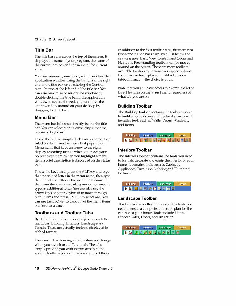
Chapter 2 Screen Layout
10 3D Home Architect® Design Suite Deluxe 6
Title BarThe title bar runs across the top of the screen. It displays the name of your program, the name of the current project, and the name of the current view.
You can minimize, maximize, restore or close the application window using the buttons at the right end of the title bar, or by clicking the Control menu button at the left end of the title bar. You can also maximize or restore the window by double-clicking the title bar. If the application window is not maximized, you can move the entire window around on your desktop by dragging the title bar.
Menu BarThe menu bar is located directly below the title bar. You can select menu items using either the mouse or keyboard.
To use the mouse, simply click a menu name, then select an item from the menu that pops down. Menu items that have an arrow to the right display cascading menus when you place your pointer over them. When you highlight a menu item, a brief description is displayed on the status bar.
To use the keyboard, press the ALT key and type the underlined letter in the menu name, then type the underlined letter in the menu item name. If the menu item has a cascading menu, you need to type an additional letter. You can also use the arrow keys on your keyboard to move through menu items and press ENTER to select one. You can use the ESC key to back out of the menu items one level at a time.
Toolbars and Toolbar TabsBy default, four tabs are located just beneath the menu bar: Building, Interiors, Landscape and Terrain. These are actually toolbars displayed in tabbed format.
The view in the drawing window does not change when you switch to a different tab. The tabs simply provide you with instant access to the specific toolbars you need, when you need them.
In addition to the four toolbar tabs, there are two free-standing toolbars displayed just below the drawing area: Basic View Control and Zoom and Navigate. Free-standing toolbars can be moved around on the screen. There are more toolbars available for display in your workspace options. Each one can be displayed in tabbed or non-tabbed format — the choice is yours.
Note that you still have access to a complete set of Insert features on the Insert menu regardless of what tab you are on.
Building ToolbarThe Building toolbar contains the tools you need to build a home or any architectural structure. It includes tools such as Walls, Doors, Windows, and Roofs.
Interiors ToolbarThe Interiors toolbar contains the tools you need to furnish, decorate and equip the interior of your home. It contains tools such as Cabinets, Appliances, Furniture, Lighting and Plumbing Fixtures.
Landscape ToolbarThe Landscape toolbar contains all the tools you need to create a complete landscape plan for the exterior of your home. Tools include Plants, Fences/Gates, Decks, and Irrigation.

User’s Guide 11
Catalog Panel 2
Terrain ToolbarThe Terrain toolbar contains tools that you can use to design a realistic terrain for your model, which is especially important in 3D views. Tools include Hills/Valleys, Slopes, Paths, Retaining Walls, and Site Boundary.
Basic View Control ToolbarThe Basic View Control toolbar contains several essential view-related tools. The toolbar’s building location drop box displays the current building location, which is important when inserting elements in your drawing. The toolbar also lets you quickly switch between 2D view and 3D view. A display mode button lets you choose the current display type for the view (wireframe, hidden line, etc.).
Zoom and Navigate ToolbarZoom tools on the Zoom and Navigate toolbar include Zoom Realtime, Zoom Window, and Pan. Note that if you are in a 3D Perspective view, only the Zoom Realtime zoom tool is available. The navigation features on the toolbar (Walk Around, Fly Around, Look Around, Slide) are only active when you are in a 3D view. These tools let you change the view in real time using your mouse.
Catalog PanelThe catalog panel, located on the right side of the screen, displays the elements contained in the program’s Master Catalog, or whatever catalog is currently open. This is where you select elements to insert into your drawing.

Chapter 2 Screen Layout
12 3D Home Architect® Design Suite Deluxe 6
The content of the catalog panel changes depending on which Insert tool is currently selected, or was last selected. For example, if you select the Doors tool, you will see doors displayed in the catalog panel.
The top window of the catalog panel displays a list of groups specific to the current element type. For example, if Doors is the current tool, you will see groups such as Hinged, Entry and Bi-Fold.
The middle window of the catalog panel displays all the element types available in the currently selected group. For example, if the Hinged door group is currently selected, you will see a list of hinged door sizes in the element window.
The lower window of the catalog panel displays a 3D rendered preview of the currently selected element. You can rotate the image around by clicking and dragging with your mouse. Note, however, that the preview is for viewing purposes only within the catalog panel. The orientation of the element in the preview window has no effect on the orientation of the element when you insert it in your plan. You can change an element’s orientation after you have inserted it in the plan.
You can also right-click in the preview window and select a different display mode for the image, or switch the preview to a 2D plan view.
Status BarThe Status bar is located at the bottom of the screen. It displays helpful prompts while you are working on your design project. For example, if you are inserting a wall, it may display “Pick first insertion point”. The Status bar also includes a selection of drawing aid buttons such as ORTHO and OBJSNAP.

13
Chapter
The first question many people ask when they sit down with a new piece of software is, “Where do I start”? 3D Home Architect® Design Suite’s House Builder Wizard is the perfect way to start a project, because it builds a house for you instantly! All you need to do is specify how many stories you want to create, select a general house shape, define the building dimensions, then select the general style for the walls, roof, floors and foundation. In a few mouse clicks, you’ll have a basic structure that you can edit and add to.
Once your basic model is built you can add things like interior walls, doors, windows, stairs and furnishings.
House Builder Wizard

Chapter 3 House Builder Wizard
14 3D Home Architect® Design Suite Deluxe 6
Using the House Builder Wizard By default, the House Builder Wizard launches every time you start a new project.
The House Builder Wizard is a handy, easy-to-use tool that instantly builds a basic house for you based on factors that you specify while stepping through the Wizard. These factors include:
• number of floors• wall height• foundation type• building shape • building dimensions• garage type and size• materials used for walls, roof, floors, etc.
The resulting house includes exterior walls, footings and foundation walls (or concrete slab), a roof, and a floor.
Once the house has been created in your drawing area, you can edit all aspects of it and add to it to suit your needs.
To use the House Builder Wizard:1. If you haven’t already done so, click the Start
a New Project button in the startup dialog, or select File > New if the program is already running.
2. On the House Builder screen, click Next.
3. From the Number of Floors drop box, select the number of floors you would like the house to have (not including the basement level).
4. In the Floor to Ceiling Height edit box, type the desired wall height for each floor level.
5. In the Foundation Type area, select the type of foundation you want to create. Choose from Concrete Slab, Full Basement, or Foundation Walls w/ Crawl Space.
6. If you selected the Full Basement or Foundation Walls w/Crawl Space, specify the elevation of the ground floor relative to the ground in the Ground Floor Height above Terrain edit box.

User’s Guide 15
Using the House Builder Wizard 3
7. Click Next.
8. Select the general house shape by clicking one of the graphics in the General House pane.
9. Once you’ve selected a house shape, make a selection in the Garage Position pane to specify where you want to put the garage. If you don’t want a garage, select the first option.
10. Click Next.
11. In the Building Size area, specify the desired dimensions for the house by entering values in the edit boxes. The edit box labels correspond to the labels on the image in the left pane.
12. In the Garage area, select either Single, Double or Triple from the Type drop box.
Then, using the dimensioned graphic as an aid, specify the desired offset of the garage from the exterior wall corner.
13. Click Next.
14. From the Building Configuration drop box, select the general style for your home (contemporary, country or traditional). The pre-set material selections for the elements in your house are displayed in the lower pane. You can select different materials if you want — just click the button of the element you want to change and make a selection from the catalog.
15. Click Next.
16. Click Finish to build the house.

Chapter 3 House Builder Wizard
16 3D Home Architect® Design Suite Deluxe 6
Tip: You can create your own custom configuration of element styles that can be saved for use in any project. See Creating a Custom House Builder Wizard Configuration on page 376.
Running the House Builder Wizard When a Drawing is OpenIf you have disabled the House Builder Wizard in your program settings, or have cancelled out of the House Builder Wizard when starting a new drawing, you can launch it manually from the Tools menu.
Note: Running the House Builder Wizard will delete all existing building elements in the current project. It will not, however, remove the terrain or any landscaping elements you have inserted.
To run the House Builder Wizard when a drawing is open:1. Select Tools > Design Wizards > House
Builder.
2. Click OK in the warning dialog. The House Builder Wizard launches.
Preventing the House Builder Wizard from LaunchingBy default, the House Builder Wizard launches every time you start a new project. You can stop the House Builder Wizard from appearing if you want. If you disable it, a new blank drawing will open when you start a new project.
To disable the House Builder Wizard:1. Select Settings > Program Settings or
click the Program Settings button on the Settings toolbar.
2. In the Program Settings dialog, select the General tab.
3. In the Startup area, uncheck the Launch House Builder wizard when starting new drawing check box.
4. Click OK.
Note: You can still run the House Builder Wizard from the Tools > Design Wizards menu when a drawing is open.

17
Chapter
When you insert an element in your drawing, it is inserted on the current building location. It is important to define your building locations before inserting elements, since building locations are the key to organizing elements and inserting them at the correct height in your model.
If you used the House Builder Wizard to start your project, your main building locations are set up for you. Their settings depend on the selections you made in the House Builder Wizard. If you are drawing from scratch, the program’s default drawing templates have three pre-defined building locations: Foundation, Ground Floor, and Second Floor. You can change the settings for existing building locations as well as add and delete locations.
This chapter describes how to define your building locations, and identify the current building location when adding elements to your design.
Building Locations

Chapter 4 Building Locations
18 3D Home Architect® Design Suite Deluxe 6
Defining Building LocationsWhen you define building locations, you are basically doing two things:
• setting the wall height for each floor (level) in your model
• specifying where each floor is positioned relative to the ground (zero)
To view building location settings:1. Select Settings > Building Locations,
or click the Building Locations button on the Settings toolbar.
Below is a brief description of each building location property.
Number. A reference number for the location.
Name. The location’s name (e.g. Ground Floor).
Floor Level. Height of floor base above ground level (0).
Head Height. Height of tops of windows and wall openings relative to the floor level.
Ceiling Height. Height of underside of ceiling surface relative to the floor level.
Wall Height. Physical height of the walls on the location.
By default, if you are drawing from scratch, the Foundation location has a Floor Level of -1’, meaning the base of the foundation starts one foot below the ground. (In other words, it is not a full basement.) The Wall Height of the Foundation location is 1’, meaning the foundation wall runs 1’ up from the foundation floor. The top of the
foundation wall would be even with the ground. These are typical settings for someone who isn’t interested in creating a basement. If you wanted to create a full basement, you could change the Floor Level to -8’ and the Wall Height to 8’.
By default, the Ground Floor and Second Floor locations each have their Wall Height set to 8’. The Floor Level of the Ground Floor is set to 0. The Floor Level of the Second Floor location is set to 9’. This leaves a 12” space between the Ground Floor walls and Second Floor walls, which is needed to fit the floor structure of the ground floor.
To change the properties of a building location:1. In the Building Locations dialog, click on
the property you want to change. You can change location names or any of the numerical settings.
2. Type the value you want.
3. Press Enter.
To add a new building location:1. In the Building Locations dialog, click the
Add Location button. A new location is added to the bottom of the list.
Note: By default the new location will adopt the numerical settings of the currently selected location.
2. Specify the location’s properties. To specify a property, click on the current value, type the new value, then press Enter.
Note: When you add a location to your list, it does not become the current location unless you select it in the list or edit its properties.
To delete a building location:1. In the Building Locations dialog, click on
one of the location’s fields to make it the current location.
2. Click Delete Location.
Note: You cannot delete a location if it contains any elements. Also, you cannot delete a location if it is the only one in the list.

User’s Guide 19
Current Building Location 4
Current Building LocationBefore inserting an element in your drawing you should make sure that the building location you want to insert the element on is the current building location.
To identify the current building location:• Take a look at the building locations drop box
on the Basic View Control or Advanced View Control toolbar.
or
• See which location is checked in the Building Locations dialog.
To make a different location current within the current view:• Click on the building locations drop box on
the Basic View Control or Advanced View Control toolbar and select the desired location.
or
• In the Building Locations dialog, click in the far left field of the location you want to make current. A check mark indicates the location is now current.
Location DimmingWhen a particular location is current, elements on all other visible locations are dimmed. This makes it easier to insert and edit elements on the current location because it is more obvious which elements are part of the current location.
By default, elements on other locations are dimmed by 90%. You can adjust the dimming so that it is lighter or darker according to your preference.
To change the dimming percentage:1. Select Settings > Program Settings or
click the Program Settings button on the Settings toolbar.
2. In the Program Settings dialog, select the Workspace tab.
3. Type the desired dimming percentage in the Dimming Percentage edit box, or use the arrows to scroll up or down through a list of values.
4. Click OK.
Check mark identifiesthe current location


21
Chapter
Whether you have automatically built a house using the House Builder Wizard, or have started a drawing from scratch, you will insert a variety of elements to create your home design.
Everything is point-and-click in 3D Home Architect® Design Suite, making it extremely simple to use and leaving you free to be as creative as you like. All elements are intelligent and know what they are in relation to other elements. For example, a door can only be inserted in a wall. 3D Home Architect® Design Suite automatically displays dimensions as you draw, making it even easier to create accurate drawings right from the start.
While working on your project, you will probably want to edit it as you go. You can select elements by clicking on them, or by drawing a selection window around them.
This chapter describes the basics of inserting elements, and selecting them for editing.
Drawing & Editing Basics

Chapter 5 Drawing & Editing Basics
22 3D Home Architect® Design Suite Deluxe 6
Inserting ElementsWhen you select a tool from the Insert menu or one of the insertion toolbars, you are in Insertion mode. To insert an element, you select it in the catalog panel, then click in your drawing area.
Many elements can be inserted with a single mouse click. Single-click elements include doors, windows, stairs, columns, cabinets, furniture, appliances, light fixtures, electrical elements, plumbing fixtures, and plants. Line-drawn elements, like walls and railings, require that you select two points to define the element’s start point and end point. The points you pick determine the element’s length and angle. Area-drawn elements, such as pads, fills and plateaus, are drawn by picking a series of points to define their outline.
In many cases, on-screen dimensions are displayed as you draw, making it easy to create line-drawn and area-drawn elements at the correct length or size, and insert elements like doors and windows precisely where you want them in a wall.
Once you insert an element in your drawing area, you can:
• Continue inserting the same element• Select a different element in the catalog to
insert• Right-click and select Finish to end the
command and return to Selection mode
Tip: When an Insert tool is active, double-clicking inserts the element and finishes the command at the same time. Note, however, that double-clicking after you’ve already inserted an element will, in most cases, insert another element.
Tip: If you are in Selection mode, you can insert any element currently accessible in the catalog by clicking the desired element in the catalog and dragging your pointer into the drawing area.
Note: If you don’t see the exact element you want to insert in the catalog, you can create custom elements to suit your needs. See Adding and Editing Elements in a Catalog on page 335.
Selecting an Insertion Method for Line-Drawn ElementsSome elements, like walls and railings, are drawn by picking two or more points. By default, line-drawn elements use the Pick and drag insertion method. With this method, you keep the mouse button depressed after clicking the first point, drag the mouse to draw the element, then release your mouse button to select the next point.
If you prefer to pick points without dragging, you can select the Pick Points insertion method. With this method you do not have to keep your mouse button depressed to draw the element (i.e. you do not have to click and drag the mouse). Once you’ve selected the first point, you can simply move your mouse in the direction you want the element to run, then click to select the next point.
To select an insertion method for line-drawn elements:1. Select Settings > Program Settings or
click the Program Settings button on the Settings toolbar.
2. In the Program Settings dialog, select the Drawing Aids tab.
3. In the Insertion Method area, select either Pick Points or Pick and drag.
4. Click OK.
Inserting Ceilings AutomaticallyIf you want ceilings to be inserted automatically when you draw a wall layout, you need to enable the Automatically Insert Ceilings option. By default, a 1/2” drywall ceiling is inserted, or whatever ceiling type was last selected in the catalog. You can edit the ceiling type later if you want.
To enable or disable automatic ceiling insertion:1. Select Settings > Program Settings or
click the Program Settings button on the Settings toolbar.
2. In the Program Settings dialog, select the Drawing Aids tab.

User’s Guide 23
Going into Selection Mode for Editing 5
3. Check or uncheck the Automatically Insert Ceilings check box.
4. Click OK.
Note: You can also insert ceilings separately using one of the Insert > Ceilings tools.
Tip: The underside of a floor can also serve as a ceiling.
Going into Selection Mode for EditingWhen you have finished using an insertion tool, either by double-clicking or selecting Finish from the right-click menu, you automatically go into Selection mode. When in Selection mode, you can select elements in your drawing area and edit them.
You can also go into Selection mode by clicking the Select/Edit button on any insertion toolbar, or by selecting Select/Edit from the Edit menu.
Disabling Pre-SelectionWhen pre-selection is turned on, elements highlight when you hover your cursor over them. Tooltips are also displayed that tell you what the elements are as they are highlighted. By default, pre-selection is enabled. On some systems, disabling pre-selection can help improve program speed.
To disable pre-selection:1. Select Settings > Program Settings or
click the Program Settings button on the Settings toolbar.
2. In the Program Settings dialog, select the Drawing Aids tab.
3. In the Visual Aids area, uncheck the Enable Pre-Selection check box.
4. Click OK.
Selecting Elements for EditingWhen in Selection Mode, you can select elements for editing. You can select individual elements, a group of elements, or all elements.
When an element is selected, it is highlighted in a different color (usually light green). One or more handles are also displayed on the element.
When you are in 3D view, all elements on all locations are selectable. When you are in 2D plan view, only elements on the current building location are selectable. However, you can change this if you want. See Making Elements on All Locations Selectable in 2D Plan View on page 24.
If you are having trouble selecting the element you want, you may want to use the View Filter to make other elements non-selectable. This makes selection of the element much easier. See Selection Filtering on page 37.
Note: Automatic floors and ceilings cannot be selected in 2D. They can only be selected in 3D.
To select a single element:1. Click on the element.
To select multiple elements by clicking:1. Click the first element you want to select.
2. Hold down the Shift key and click on the rest of the elements you want to select. The most recent selection is green and prior selections are blue.
To select a group of elements by creating a selection window:1. Going from either left to right, or right to left,
drag a selection window around the elements you want to select. Any elements touching the selection window will be selected (they do not need to be totally enclosed).
To select all elements on the current location:1. Select Edit > Select All.
To re-select the elements you last selected:1. Select Edit > Select Previous.

Chapter 5 Drawing & Editing Basics
24 3D Home Architect® Design Suite Deluxe 6
Deselecting ElementsWhen you select elements, you can remove individual elements from your selection set. You can also deselect everything that is currently selected.
To deselect individual elements:1. Hold down your Shift key.
2. Click the element you want to deselect.
To deselect everything in your selection set:1. Select Edit > Deselect All, or right-click in
the drawing area and select Deselect All, or simply click in a blank spot somewhere else in the drawing area.
Making Elements on All Locations Selectable in 2D Plan ViewBy default, only elements on the current building location can be selected in 2D plan view, even if elements on other locations are visible. If you want to make elements on all locations selectable, you need to change one of your program settings.
To make elements on all locations selectable in 2D plan view:1. Select Settings > Program Settings or
click the Program Settings button on the Settings toolbar.
2. In the Program Settings dialog, select the Drawing Aids tab.
3. In the Drawing Assistance area, uncheck the Select elements on current location only while in plan view check box.
4. Click OK.
Accessing Edit ToolsMost elements can be moved once they are selected by simply clicking and dragging them. Some can also be stretched or rotated. You can access a full menu of edit tools by right-clicking in the drawing area, or by selecting Edit > Modify Elements.
Menus vary depending on the element selected. Typical tools are Properties, Move, Rotate,
Duplicate, and Delete. If two types of elements are selected (such as a floor and a wall), only tools that are common to both element types are available.
Each chapter includes editing instructions specific to the contents of that chapter. For information about general editing, see Editing Your Design on page 253.

2D and 3D Viewing page 27
View Filter page 33
Controlling the View
Part 2


27
Chapter
3D Home Architect® Design Suite Deluxe offers a variety of options for viewing your design in 2D and 3D.
When working in 2D plan view, you can magnify or reduce the view using the Zoom Realtime tool. You can also magnify a selected area using the Zoom Window tool. The Zoom to Fit tool magnifies your design so it fills the drawing area, creating the largest view possible. The Pan tool lets you pan the view in any direction by simply clicking and dragging.
You can instantly switch to 3D view with a couple of mouse clicks. You can choose from the realistic 3D Perspective view, which is like viewing your house from a distance, or 3D Overview, which eliminates distance from the view and lets you see the house from above.
While viewing in 3D you can choose from a variety of display types, including Wireframe, Patterned and Rendered.
Using the Framing Visibility options you can view your house frame, which consists of wall, roof, floor and ceiling framing.
This chapter describes all basic 2D and 3D viewing features. For information about advanced viewing features, see page 321.
2D and 3D Viewing

Chapter 6 2D and 3D Viewing
28 3D Home Architect® Design Suite Deluxe 6
Viewing the 2D PlanWhen you start a drawing, the default view is a 2D plan view. It shows your model in a "flat" view, as if you were looking at it from above. 2D Plan view is ideal for creating a floor plan.
To display your model in 2D plan view:• Select View > 2D Plan View, or• Click the 2D Plan View button on the
Basic View Control or Advanced View Control toolbar, or
• Right-click in the drawing area and select 2D Plan View
By default, all locations are visible at the same time. However, any locations other than the current location are dimmed. You can control which elements and locations are displayed by using the View Filter. See Filtering the Display on page 34.
While in 2D plan view you can zoom in and out, and pan your drawing.
Viewing a 2D Designer’s ViewBy default, your design is displayed in a wireframe 2D plan view. You can use the 2D Designer’s View tool to quickly display a rendered version of the 2D plan view. In a rendered view, materials are applied to the elements and terrain, creating a more realistic view. For example, if you have a shingled roof on your model, you will actually see the shingles in 2D Designer’s View.
To view a 2D Designer’s View:1. Select View > 2D Designer’s View, or
click the 2D Designer’s View button on the Basic View Control or Advanced View Control toolbar.
Note: If you want to be able to see inside the model, you can use the View Filter to hide elements like the roof or ceilings. See Filtering the Display on page 34.

User’s Guide 29
Viewing in 3D 6
Viewing in 3DYou can instantly switch to 3D view by selecting either the 3D Perspective or 3D Overview tool.
In a 3D Perspective view, the scale of an element decreases according to its distance from the viewer, creating a more real-world view.
To view a 3D perspective view:1. Select View > 3D Model View > 3D
Perspective, or click the 3D Model View button on the Basic View Control or Advanced View Control toolbar and select 3D Perspective.
The 3D Overview is an orthographic view, where the view is set from a common angle, and distance is eliminated from the view. This creates an instant close-up of your design.
To view a 3D overview:1. Select View > 3D Model View > 3D
Overview, or click the 3D Model View button on the Basic View Control or Advanced View Control toolbar and select 3D Overview.
Tip: If you have your cameras turned on in 2D, you can switch to a 3D view by selecting a camera, right-clicking it, then selecting Look Through.
Note: By default, 3D views are displayed in Rendered mode. For information about changing the display mode, see Changing the Display Mode on page 30. For information about moving around in a 3D view, or creating or customizing 3D views, see Custom Viewing on page 321.

Chapter 6 2D and 3D Viewing
30 3D Home Architect® Design Suite Deluxe 6
Zooming In and OutThe Zoom Realtime tool continuously magnifies or shrinks the view as you click and drag with your mouse. You can zoom in and out in 2D plan view or any 3D view.
To zoom in and out:1. Select View > Zoom and Navigate >
Zoom Realtime, or click the Zoom Realtime button on the Zoom and Navigate toolbar.
2. To zoom in, click and drag toward the top of the screen. To zoom out, click and drag toward the bottom of the screen.
3. When the view is the desired size, release your mouse button.
Tip: You can also zoom in and out using the scroll button on your mouse.
Zooming a Selected AreaUsing the Zoom Window tool you can magnify a particular area of your design by drawing a selection window around it.
To zoom a selected area:1. Select View > Zoom and Navigate >
Zoom Window, or click the Zoom Window button on the Zoom and Navigate toolbar. Your cursor becomes a magnifying glass.
2. Click and drag a selection window around the area you want to magnify.
Note: The Zoom Window tool is not available in 3D perspective views.
Zooming to Fit the Drawing AreaThe Zoom to Fit tool instantly extends your drawing to the edges of the drawing area. This ensures your entire drawing is visible at the most maximized view possible, and makes full use of the drawing area.
To zoom the drawing to fit the drawing area:1. Select View > Zoom and Navigate >
Zoom to Fit, or click the Zoom to Fit button on the Zoom and Navigate toolbar.
Note that the terrain is considered part of your drawing. If you want to zoom your model to fit the drawing area, you need to turn the terrain off before using Zoom to Fit.
Note: The Zoom to Fit tool is not available in 3D perspective views.
Panning Across a DrawingUsing the Pan tool you can move the current view of your design to bring a particular part of your design into view. This is especially useful when the area you want to view is currently not visible because you have zoomed in on your drawing.
To pan the current view:1. Select View > Zoom and Navigate >
Pan, or click the Pan button on the Zoom and Navigate toolbar.
2. Click in the drawing.
3. Hold your mouse button down.
4. Drag the view in the direction you want to pan.
5. Release the mouse button.
Note: The Pan tool is not available in 3D perspective views.
Changing the Display ModeBy default, your design is displayed in Wireframe mode when you are in 2D plan view. When you switch to a 3D view, the default display mode is Rendered mode. There are five display modes you can choose from.
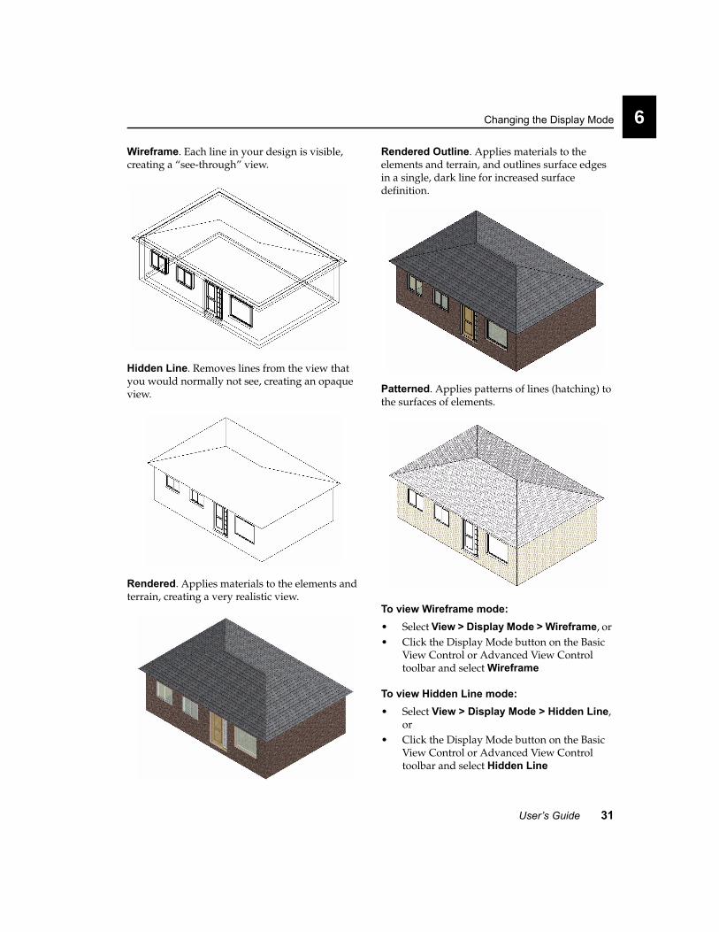
User’s Guide 31
Changing the Display Mode 6
Wireframe. Each line in your design is visible, creating a “see-through” view.
Hidden Line. Removes lines from the view that you would normally not see, creating an opaque view.
Rendered. Applies materials to the elements and terrain, creating a very realistic view.
Rendered Outline. Applies materials to the elements and terrain, and outlines surface edges in a single, dark line for increased surface definition.
Patterned. Applies patterns of lines (hatching) to the surfaces of elements.
To view Wireframe mode:• Select View > Display Mode > Wireframe, or • Click the Display Mode button on the Basic
View Control or Advanced View Control toolbar and select Wireframe
To view Hidden Line mode:• Select View > Display Mode > Hidden Line,
or • Click the Display Mode button on the Basic
View Control or Advanced View Control toolbar and select Hidden Line

Chapter 6 2D and 3D Viewing
32 3D Home Architect® Design Suite Deluxe 6
To view Rendered mode:• Select View > Display Mode > Rendered, or • Click the Display Mode button on the Basic
View Control or Advanced View Control toolbar and select Rendered
To view Rendered Outline mode:• Select View > Display Mode > Rendered
Outline, or • Click the Display Mode button on the Basic
View Control or Advanced View Control toolbar and select Rendered Outline
To view Patterned mode:• Select View > Display Mode > Patterned, or • Click the Display Mode button on the Basic
View Control or Advanced View Control toolbar and select Patterned
Displaying FramingWalls, floors, ceilings and roofs have a framing configuration assigned to them in their properties. You can instantly view just your house frame using the Display Framing tool, then return to a regular view of your model at any time.
To display framing:1. Select View > Framing Visibility > Display
Framing.
Note: You can also use the View Filter to display framing. However, the framing will not be displayed on its own unless you turn everything else off.
Note: Framing cannot be selected for editing. It is available for viewing purposes only.
To return to a non-framed view:1. Select View > Framing Visibility > Display
All But Framing.
To change framing members or member spacing:1. In non-framed view, select the wall, floor,
ceiling or roof whose framing you want to change.
2. Right-click and select Properties, or select Edit > Modify Elements > Properties.
3. On the Basic property page, click the Specify Framing button.
4. Select the desired framing members and specify the spacing you want.
5. Click OK.

33
Chapter
The program’s unique View Filter feature lets you decide which elements or locations you want displayed at any given time. For example, you may want to hide your roof and ceilings to be able to see inside the model. It also lets you make selected elements non-selectable, which is sometimes necessary when trying to select a particular element in your drawing, like a floor or ceiling.
View Filter

Chapter 7 View Filter
34 3D Home Architect® Design Suite Deluxe 6
Filtering the DisplayThe View Filter provides precise control over what elements and locations are displayed in a view at any given time.
You can display/hide:• an entire location, or multiple locations• building elements on a specific location or
multiple locations• selected or all landscaping elements • text and dimension elements
Note: Using the View Filter does not delete elements from your drawing. It just hides them from view.
To access the View Filter:• Select View > View Filter or click the
View Filter button on the Basic View Control or Advanced View Control toolbar.
The View Filter dialog contains three tabs: Building, Landscape and Notation. The Building tab lists all elements types. If you expand an element, a list of building locations is displayed
below the element name. If you choose to sort by location, a list of building locations is displayed with a list of elements under each one. The Landscape tab contains a list of exterior landscaping elements, and the Notation tab contains text, dimensions, project trace images, and electrical wiring.
The icons in the Display column indicate whether or not that location or element is currently displayed. Clicking an icon toggles the icon to the opposite state (on or off).
Clicking Display All turns on all locations and elements on the current tab. Clicking Display None turns off all locations and elements on the current tab.
The View Filter dialog also lets you control whether or not individual locations and elements can be selected. See Selection Filtering on page 37.
Displaying/Hiding Building ElementsBuilding elements are things like walls, doors and windows - things that make up an architectural model. Using the View Filter you can display or hide selected element types on all or selected building locations.
To display or hide building elements:1. Select View > View Filter or click the
View Filter button on the Basic View Control or Advanced View Control toolbar.
2. In the View Filter dialog, select the Building tab.
Display FilterTabsElements
Location or element is turned on
Location or element is turned off
If sorting by element, this means that the element is displayed on some locations and not on others. If sorting by location, it means that some elements on the location are displayed and some are not.

User’s Guide 35
Displaying/Hiding Building Locations 7
3. In the Sort By area, make sure the Element radio button is selected.
4. If you want to change the visibility of an element on all locations, click the element’s eye icon in the Display column. If you want to filter an element on a specific location, click the element’s plus sign (+) to display a list of building locations. Then, click the location’s eye icon in the Display column.
You can also filter elements by location. If you enable the Location radio button in the Sort By area, a list of building locations is displayed. You can then expand the location you want to filter elements on to display a list of elements. Toggling the eye icons of elements in this list filters elements on the selected location.
If you want to make all elements on all locations visible, click the Display All button. If you want to make all elements on all locations non-visible, click Display None.
5. Once you’ve selected what you want to filter, click OK.
Displaying/Hiding Building LocationsYou can turn individual locations on or off. When you turn a location off, all elements on that location are hidden from view.
To display or hide entire locations:1. Select View > View Filter or click the
View Filter button on the Basic View Control or Advanced View Control toolbar.
2. In the View Filter dialog, select the Building tab.
3. In the Sort By area, enable the Location radio button. A list of building locations is displayed in the window.
4. Click the eye icon next to the name of the location you want to display or hide.
5. Click OK.
Displaying/Hiding Landscape ElementsLandscape elements include things like the terrain, site boundary, paths and plants. Using the View Filter you can display or hide selected landscape element types.
To filter landscape elements:1. Select View > View Filter or click the
View Filter button on the Basic View Control or Advanced View Control toolbar.
Element is turned on
Element is turned off
EyeIcon
Location is turned on
Location is turned off

Chapter 7 View Filter
36 3D Home Architect® Design Suite Deluxe 6
2. In the View Filter dialog, select the Landscape tab. A list of landscape elements is displayed.
3. Click the eye icons in the Display column to turn elements on or off.
4. Click OK.
Displaying/Hiding TextUsing the View Filter you can display or hide text in your drawing.
To filter text from view:1. Select View > View Filter or click the
View Filter button on the Basic View Control or Advanced View Control toolbar.
2. In the View Filter dialog, select the Notation tab.
3. In the Text row, click the eye icon in the Display column to turn text on or off.
4. Click OK.
Displaying/Hiding DimensionsUsing the View Filter you can display or hide dimensions in your drawing.
To filter dimensions from view:1. Select View > View Filter or click the
View Filter button on the Basic View Control or Advanced View Control toolbar.
2. In the View Filter dialog, select the Notation tab.
3. In the Dimension row, click the eye icon in the Display column to turn dimensions on or off.
4. Click OK.
Displaying/Hiding Electrical WiringUsing the View Filter you can display or hide electrical wiring in your drawing.
To filter electrical wiring from view:1. Select View > View Filter or click the
View Filter button on the Basic View Control or Advanced View Control toolbar.
Element is turned on
Element is turned off
Text is turned on
Text is turned off
Dimensions are turned on
Dimensions are turned off

User’s Guide 37
Displaying/Hiding Project Trace Images 7
2. In the View Filter dialog, select the Notation tab.
3. In the Electrical Wiring row, click the eye icon in the Display column to turn wiring on or off.
4. Click OK.
Displaying/Hiding Project Trace ImagesIf you have used the Project Trace Image tool to import a plan into your project, you can hide the image if you want using the View Filter. This is an alternative to deleting the image.
To filter project trace images from view:1. Select View > View Filter or click the
View Filter button on the Basic View Control or Advanced View Control toolbar.
2. In the View Filter dialog, select the Notation tab.
3. In the Project Trace Image row, click the eye icon in the Display column to turn wiring on or off.
4. Click OK.
Selection FilteringWhen your model contains a number of elements, it can sometimes be difficult to select certain ones because of proximity or overlapping edges. Floors, for example, can be very difficult to select because floor edges are typically right up against your walls. Also, small elements can be hard to select in an extreme zoomed out view, even in 2D.
You can use the View Filter to stop certain elements from being selected. You can even prevent entire building locations from being selected.
To access the View Filter:1. Select View > View Filter or click the
View Filter button on the Basic View Control or Advanced View Control toolbar.
The View Filter dialog contains three tabs: Building, Landscape and Notation. The Building tab lists all element types. When you expand an element, all of your building locations are listed below the element. The Landscape tab contains a
Wiring is turned on
Wiring is turned off
Project trace image is turned on
Project trace image is turned off
Selection FilterTabsElements

Chapter 7 View Filter
38 3D Home Architect® Design Suite Deluxe 6
list of exterior landscaping elements, and the Notation tab contains text, dimensions, project trace images, and electrical wiring.
The icons in the Selection column indicate whether or not that location or element is currently selectable. Clicking an icon toggles the icon to the opposite state (selectable or non-selectable).
Making Building Elements Selectable or Non-SelectableBuilding elements are things like walls, doors and windows - things that make up an architectural model. Using the View Filter you can make individual element types selectable or non-selectable on all or selected building locations.
To change the selectability of building elements:1. Select View > View Filter or click the
View Filter button on the Basic View Control or Advanced View Control toolbar.
2. In the View Filter dialog, select the Building tab.
3. In the Sort By area, make sure the Element radio button is selected.
4. If you want to change the selectability of an element on all locations, click the element’s filter icon in the Selection column. If you want to filter an element on a specific location, click the element’s plus sign (+) to display a list of building locations. Then, click the location’s filter icon in the Selection column.
You can also filter elements by location. If you enable the Location radio button in the Sort By area, a list of building locations is displayed. You can then expand the location you want to filter elements on to display a list of elements. Toggling the filter icons of elements in this list filters elements on the selected location.
If you want to make all elements on all locations selectable, click the Select All button. If you want to make all elements on all locations non-selectable, click Select None.
5. Once you’ve selected what you want to filter, click OK.
Making Building Locations Selectable or Non-SelectableWhen you make a location non-selectable, no elements on that location can be selected in any view.
To make a location selectable or non-selectable:1. Select View > View Filter or click the
View Filter button on the Basic View Control or Advanced View Control toolbar.
2. In the View Filter dialog, select the Building tab.
3. In the Sort By area, enable the Location radio button. A list of building locations is displayed in the window.
Element or location is selectable
Element or location is not selectable
Element is selectable
Element is not selectable
FilterIcon

User’s Guide 39
Making Landscape Elements Selectable or Non-Selectable 7
4. Click the filter icon next to the name of the location you want to make selectable or non-selectable.
If you want to make all locations selectable, click the Select All button. If you want to make all locations non-selectable, click Select None.
5. Once you’ve made your selections, click OK.
Making Landscape Elements Selectable or Non-SelectableLandscape elements include things like the terrain, site boundary, paths and plants. Using the View Filter you can make selected landscape element types selectable or non-selectable.
To make landscape elements selectable or non-selectable:1. Select View > View Filter or click the
View Filter button on the Basic View Control or Advanced View Control toolbar.
2. In the View Filter dialog, select the Landscape tab. A list of landscape elements is displayed.
3. Click the filter icons in the Selection column to toggle selectability on or off.
4. If you want to make all landscape elements selectable, click the Select All button. If you want to make all landscape elements non-selectable, click Select None.
5. Click OK.
Making Text Selectable or Non-SelectableUsing the View Filter you can make text selectable or non-selectable.
To make text selectable or non-selectable:1. Select View > View Filter or click the
View Filter button on the Basic View Control or Advanced View Control toolbar.
2. In the View Filter dialog, select the Notation tab.
3. In the Text row, click the filter icon in the Selection column to toggle selectability on or off.
4. Click OK.
Location is selectable
Location is not selectable
Element is selectable
Element is not selectable
Text is selectable
Text is not selectable

Chapter 7 View Filter
40 3D Home Architect® Design Suite Deluxe 6
Making Dimensions Selectable or Non-SelectableUsing the View Filter you can make dimensions selectable or non-selectable.
To make dimensions selectable or non-selectable:1. Select View > View Filter or click the
View Filter button on the Basic View Control or Advanced View Control toolbar.
2. In the View Filter dialog, select the Notation tab.
3. In the Dimension row, click the filter icon in the Selection column to toggle selectability on or off.
4. Click OK.
Making Electrical Wiring Selectable or Non-SelectableUsing the View Filter you can make electrical wiring selectable or non-selectable.
To make electrical wiring selectable or non-selectable:1. Select View > View Filter or click the
View Filter button on the Basic View Control or Advanced View Control toolbar.
2. In the View Filter dialog, select the Notation tab.
3. In the Electrical Wiring row, click the filter icon in the Selection column to toggle selectability on or off.
4. Click OK.
Making Project Trace Images Selectable or Non-SelectableIf you have used the Project Trace Image tool to import a plan into your project, you can use the View Filter to make the image selectable or non-selectable.
To make project trace images selectable or non-selectable:1. Select View > View Filter or click the
View Filter button on the Basic View Control or Advanced View Control toolbar.
2. In the View Filter dialog, select the Notation tab.
3. In the Project Trace Image row, click the filter icon in the Selection column to toggle selectability on or off.
4. Click OK.
Dimensions are selectable
Dimensions are not selectable
Wiring is selectable
Wiring is not selectable
Project trace image is selectable
Project trace image is not selectable

Foundation page 43
Walls page 53
Doors, Windows & Openings page 61
Floors & Ceilings page 73
Stairs, Ramps & Railings page 81
Roofs page 93
Building Your Home
Part 3


43
Chapter
If you have decided to create your project from scratch, you can do what builders do in the real world — build from the ground up. 3D Home Architect® Design Suite offers the versatility of creating a variety of foundation types. You can create a full basement, crawl space foundation, or a slab on grade.
First you need to define the foundation’s building location, if you haven’t already done so. The building location’s Floor Level variable determines how far below the ground the foundation floor will be positioned, and the Wall Height variable determines how tall the walls will be. See Defining Building Locations on page 18.
To create a basement or crawlspace foundation, you start by drawing your foundation walls. A floor is created for you automatically. You can then add support columns where needed and quickly create footings beneath walls and columns.
If you are not creating a basement or crawlspace foundation, you can use the Pads tool to quickly create a slab on grade. The slab can have any thickness you want, and by drawing its outline, you control its precise size and shape.
To begin, set your current building location on the Basic View Control toolbar to the Foundation location, or whatever location you have set up for your foundation.
Foundation

Chapter 8 Foundation
44 3D Home Architect® Design Suite Deluxe 6
Creating a Basement or Crawlspace FoundationThe first step in creating a basement or crawlspace foundation is drawing the foundation walls, which are typically made of poured concrete or concrete blocks. You can draw the entire perimeter in seconds by just pointing and clicking with your mouse.
A floor is automatically inserted when you create a closed foundation wall layout. You can change the floor type after it has been inserted if you want. If you want you can also opt to insert ceilings automatically. See Inserting Ceilings Automatically on page 22.
To draw the foundation walls:1. Make sure the current location in the
Building Locations drop box is the Foundation location, or whatever location you have set up for your foundation elements. Make sure that you have defined the correct Floor Level and Wall Height for that location in the Building Locations dialog.
2. Select Insert > Walls, or click the Walls button on the Building toolbar.
3. In the catalog panel, select the Foundation Walls category, then select the type of wall you want to insert.
4. In the drawing area, select a start point for the first wall.
5. Move your pointer in the direction you want your wall to run. A dynamic
dimension is displayed to indicate the length of the wall.
Note: By default, drawing is constrained to 5º angles. To release this constraint, turn off your Angle Snap.
6. When the wall is the length you want, click to set its endpoint.
7. Continue drawing walls until the perimeter is complete. You can add walls to the interior of the foundation layout if you want (if you are creating a cold cellar, for example).
8. Right-click and select Finish from the shortcut menu.
To move the foundation:1. Click on one of the foundation walls to select
it, then Shift+click to select the remaining walls.
2. Hover your pointer over the center grab handle on the currently selected wall to display the Move cursor.
3. Click and drag the foundation to where you want it, then release your mouse button.
To resize the foundation by stretching:1. Select the foundation wall you want to move.
All attached walls will stretch along with it when you move it.
2. Hover your pointer over the center grab handle to display the Move cursor.
3. Click and drag the wall to resize the wall layout, then release your mouse button.
Note: If you have footings attached to your walls, the footings will stretch along with the walls.

User’s Guide 45
Editing a Wall’s Height, Width or Elevation 8
To resize the foundation by editing its dimensions:1. Select one of the foundation walls. If you
want to stretch the layout left or right, select a vertical wall. If you want to stretch the layout up or down, select a horizontal wall. Dimensions are displayed on the foundation. Positioning your cursor over one of the dimensions changes your cursor to a pointing finger.
2. Click the dimension you want to edit. The Edit Dimension dialog appears.
3. Enter the new value in the Enter Distance edit box, then press Enter or click OK. The walls update automatically.
To remove the foundation:1. Select the foundation by dragging a selection
window around it, or by clicking on one wall and using Shift+click to select the remaining walls.
2. Press the Delete key on your keyboard, or right-click and select Delete, or select Edit > Modify Elements > Delete.
Editing a Wall’s Height, Width or ElevationYou can edit the size properties of a wall by making changes on the wall’s Basic property page.
To edit a wall’s size properties:1. Select the wall whose properties you want to
change. You can select multiple walls using Shift+click if you want.
2. Right-click and select Properties, or select Edit > Modify Elements > Properties.
3. In the Walls dialog, select the Basic tab.
4. Edit the properties as desired.
Width. The thickness of the wall.
Wall Height. The physical height of the wall.
Extension Below Base. The height of the wall below floor level.
5. Once the properties are set, click OK.
Lengthening and Shortening WallsYou can lengthen or shorten an individual wall by clicking and dragging one of the wall’s ends.
To lengthen or shorten a wall:1. Select the wall. A grab handle is displayed at
each wall end.
2. Hover your pointer over the wall end you want to stretch. The Stretch cursor is displayed.
3. Click and drag the wall end until it has reached the desired length.
4. Release your mouse button.
Rotating a WallYou can use the Rotate tool to rotate a wall about a selected point.
To rotate a wall:1. Select the wall.
2. Right-click and select Rotate, or select Edit > Modify Elements > Rotate.

Chapter 8 Foundation
46 3D Home Architect® Design Suite Deluxe 6
3. Position your pointer over the grab handle you want to rotate the wall around.
4. Click and drag to rotate the wall, then release your mouse button.
Curving a WallYou can curve a wall using the Curve tool. Once the tool is active, you can click and drag the wall to curve it, or select a point to curve to.
To curve a wall by clicking and dragging:1. Click the wall to select it.
2. Right-click and select Curve, or select Edit > Modify Elements > Curve.
3. Click and drag the wall to the desired curve.
4. Release your mouse button.
To curve a wall to a selected point:1. Click the wall to select it.
2. Right-click in and select Curve, or select Edit > Modify Elements > Curve.
3. Select the point you want to curve to. The wall automatically curves to the point.
4. Click to finish.
Breaking a WallYou can break a wall into two or more segments using the Break tool. The segments can then be edited individually.
To break a wall:1. Click the wall to select it.
2. Right-click in the drawing area and select Break, or select Edit > Modify Elements > Break.
3. Double-click the point where you want to break the wall. This divides the wall into two segments that can be moved, stretched or manipulated individually.
Deleting a WallYou can delete a wall in a couple of easy steps.
To delete a wall:1. Select the wall to delete. You can select
multiple walls using Shift+click.
2. Press the Delete key on your keyboard, or right-click and select Delete, or select Edit > Modify Elements > Delete.
Note: The floor will be deleted if the wall you are deleting opens up the wall layout.
Applying a Different Material to the Foundation FloorYou can use the Materials Paintbrush to quickly apply a different material such as poured concrete to the foundation floor.
To apply a material to the floor:1. Display your model in 3D view and make
sure the floor is visible in the view.
2. Select Edit > Materials Paintbrush, or click the Materials Paintbrush button on any tabbed toolbar.
3. In the catalog panel, select the material you want to apply.
4. Click on the floor surface. The material is immediately applied.
5. Right-click and select Finish.

User’s Guide 47
Inserting Strip Footings Beneath the Foundation Walls 8
Inserting Strip Footings Beneath the Foundation WallsSince foundation walls bear the weight of exterior walls above them, you need to insert footings beneath the foundation walls to transfer support for the vertical load.
Strip footings are easy to insert — just click on a wall and a footing is automatically inserted underneath the wall.
To insert strip footings under walls:1. Select Insert > Footings > Strip Footings
Attached to Walls, or click the Footings button on the Building toolbar and select Strip Footings Attached to Walls.
2. In the catalog panel, select the footing you want to insert. Typically you would choose one that is wider than the wall you are attaching it to.
3. Click on the wall you want to attach the footing to. The footing is inserted automatically. In plan view, strip footings are usually shown using a dashed line.
4. Continue inserting footings underneath each exterior foundation wall.
5. Right-click and select Finish from the shortcut menu.
Editing the Strip Footing TypeStrip footing types include rectangular, tapered and filleted. The footing type determines the footing’s general appearance.
To edit the footing type:1. Select the footing whose properties you want
to change. You can select multiple footings using Shift+click if you want.
2. Right-click and select Properties, or select Edit > Modify Elements > Properties.
3. Select the Basic tab, then click on the appropriate graphic in the Type area.
4. Click OK.
Editing the Size of Strip FootingsYou can edit the dimensions of a footing on the footing’s Basic property page.
To change the footing size:1. Select the footing.
2. Right-click and select Properties, or select Edit > Modify Elements > Properties.
3. In the Strip Footing dialog, select the Basic tab.
4. Edit the dimensions of the footing.
5. Click OK.
Moving/Stretching Strip FootingsWhen you move a strip footing, all footings attached to it move with it for a stretching effect. You can move strip footings by just clicking and dragging.
To move/stretch strip footings:1. Select the footing to move. You may need to
make walls non-selectable to be able to select the footing.

Chapter 8 Foundation
48 3D Home Architect® Design Suite Deluxe 6
2. Position your pointer over the center grab handle to display the Move cursor.
3. Click and drag the footing to move it.
4. Release your mouse button.
Note: When you move a strip footing, it becomes detached from the wall. Therefore, if you move or stretch the wall, the footing will not go with it. If you want to re-attach a footing to a wall, you will need to delete the footing, then insert a new one.
Lengthening and Shortening Strip FootingsYou can lengthen or shorten an individual footing by clicking and dragging one of the footing’s ends.
To lengthen or shorten a footing:1. Select the footing. A grab handle is displayed
at each end.
2. Hover your pointer over the end you want to stretch. The Move cursor is displayed.
3. Click and drag the footing end until it has reached the desired length.
4. Release your mouse button.
Breaking Strip FootingsYou can break a footing into two or more segments using the Break tool. The segments can then be edited individually.
To break a footing:1. Click the footing to select it.
2. Right-click in the drawing area and select Break, or select Edit > Modify Elements > Break.
3. Double-click the point where you want to break the footing.
Deleting Strip FootingsYou can delete a strip footing in a couple of easy steps.
To delete strip footings:1. Select the footing to delete. You can select
multiple footings using Shift+click.
2. Press the Delete key on your keyboard, or right-click and select Delete, or select Edit > Modify Elements > Delete.
Inserting ColumnsTypically, any bearing members in your basement require support. For example, if you have a W-type I-beam in your basement, it may be supported by steel posts at each end. Columns are an important consideration when designing your basement, especially if you intend to finish it.
When inserting columns, you can choose from a variety of wood, concrete, steel, brick and gypsum columns in various shapes and sizes.
To insert a column:1. Select Insert > Columns, or click the
Columns button on the Building toolbar.
2. In the catalog panel, select the column you want to insert.
3. Position the column where you want it, then click to insert it.
4. Right-click and select Finish from the shortcut menu.

User’s Guide 49
Editing the Column Type 8
Editing the Column TypeColumns come in a variety of materials and shapes.
To edit the column type:1. Select the column whose properties you want
to change. You can select multiple columns using Shift+click if you want.
2. Right-click and select Properties, or select Edit > Modify Elements > Properties.
3. Select the Basic tab, then click on the appropriate graphic in the Type area.
4. Click OK.
Editing the Size and Elevation of a ColumnYou can edit the dimensions of a column (e.g. height, width and depth) as well as its elevation height.
To edit the size properties of a column:1. Click on the column to select it.
2. Right-click and select Properties, or select Edit > Modify Elements > Properties.
3. Edit the properties as desired. Different column shapes will have different dimension variables. If you want to offset the base of the column from the floor (so it sits higher or lower), enter a value in the Base Offset edit box.
4. Click OK.
Moving ColumnsYou can move a column by simply clicking and dragging it.
To move a column:1. Click on the column to select it.
2. Hover your pointer over the center grab handle to display the Move cursor.
3. Click and drag the column to move it.
4. Release your mouse button.
Note: If you have a mono footing attached to the column, the footing will remain attached to the column and move with it.
Deleting a ColumnYou can remove a column in a couple of quick steps.
To remove a column:1. Click on the column to select it.
2. Press the Delete key on your keyboard, or right-click and select Delete, or select Edit > Modify Elements > Delete.
Inserting Mono Footings Under ColumnsSince support columns in your basement bear loads at a concentrated point, the load should be transferred to a proper footing.
Using the Mono Footings Attached to Columns tool you can insert a single pad footing beneath a selected column. All you have to do is select the column.
To insert a footing under a column:1. Select Insert > Footings > Mono Footings
Attached to Columns, or click the Footings button on the Building toolbar and select Mono Footings Attached to Columns.

Chapter 8 Foundation
50 3D Home Architect® Design Suite Deluxe 6
2. In the catalog panel, select the footing you want to insert. Typically you would choose one that is wider than the column you are attaching it to.
3. Click on the column you want to attach the footing to. The footing is inserted automatically.
4. Right-click and select Finish from the shortcut menu.
Editing the Mono Footing TypeMono footing types include rectangular, tapered, cylinder and cylinder tapered. The footing type determines the footing’s general appearance.
To edit the footing type:1. Select the footing whose properties you want
to change. You can select multiple footings using Shift+click if you want.
2. Right-click and select Properties, or select Edit > Modify Elements > Properties.
3. Select the Basic tab, then click on the appropriate graphic in the Type area.
4. Click OK.
Editing the Size of Mono FootingsYou can edit the dimensions of a footing on the footing’s Basic property page.
To change the footing size:1. Select the footing.
2. Right-click and select Properties, or select Edit > Modify Elements > Properties.
3. In the Mono Footing dialog, select the Basic tab.
4. Edit the dimensions of the footing.
5. Click OK.
Moving Mono FootingsYou can move a mono footing by clicking and dragging it.
To move a mono footing by clicking and dragging:1. Select the footing to move.
2. Position your pointer over the center grab handle to display the Move cursor.
3. Click and drag the footing to move it.
4. Release your mouse button.
Note: When you move a mono footing, it becomes detached from the column. Therefore, if you move the column, the footing will not go with it. If you want to re-attach a footing to a column, you will need to delete the footing, then insert a new one.
Rotating a Mono FootingYou can rotate a mono footing by simply clicking and dragging it.
To rotate a mono footing:1. Select the footing.
2. Hover your pointer over the triangular grab handle to display the Rotate cursor.
3. Click and drag to rotate the footing.
4. When the footing is at the desired rotation, release your mouse button.
Deleting Mono FootingsYou can delete a mono footing in a couple of easy steps.
To delete mono footings:1. Select the footing to remove. You can select
multiple footings using Shift+click.
2. Press the Delete key on your keyboard, or right-click and select Delete, or select Edit > Modify Elements > Delete.

User’s Guide 51
Creating a Slab Foundation 8
Creating a Slab FoundationYou can use the Pads tool to insert a concrete slab directly on your terrain. By drawing the outline of the pad, you control the precise size and shape of the slab.
After you insert the slab, you need to turn off the slab’s Hug Terrain option to make sure the slab remains flat and positioned at the Terrain Base Level specified in your Terrain Settings.
Note: Slabs created with the Pads tool are considered landscape elements that are associated with the terrain. When using the View Filter, pads are listed on the Landscape tab.
To create a slab on grade:1. Select Insert > Terrain > Pads, or click
the Pads button on the Terrain toolbar.
2. In the catalog panel, select the type of slab you want to insert.
3. Select a start point for the slab.
4. Continue selecting points to define the outline of the slab. Note that the last point picked always closes back to the start point, so you don’t have to pick the start point again.
5. Right-click and select Finish from the shortcut menu.
To disable the slab’s Hug Terrain option:1. Click on the edge of the slab to select it.
2. Right-click and select Properties, or select Edit > Modify Elements > Properties.
3. On the Basic property page, uncheck the Hug Terrain? check box.
4. Click OK.
Moving a SlabYou can move a slab by selecting all of its sides, then clicking and dragging it.
To move the entire slab:1. Click on the edge of the slab to select it.
2. Right-click and select Move Whole Element, or select Edit > Modify Elements > Move Whole Element.
3. Click and drag the slab to move it, then release your mouse button.
Resizing a SlabYou can resize a slab by stretching one of its edges.
To resize the slab by stretching it:1. Click on the edge of the slab to select it.
2. Click on the edge you want to stretch.
3. Hover your pointer over the grab handle to display the Move cursor.
4. Click and drag to stretch the slab.
5. Release your mouse button.
Reshaping a SlabYou can change the shape of a slab by clicking and dragging its corners.
To reshape a slab:1. Click on the edge of the slab to select it. A
grab handle is displayed at each corner.
2. Click and drag a corner grab handle to stretch the slab.
3. Release your mouse button.
2 3
1 4

Chapter 8 Foundation
52 3D Home Architect® Design Suite Deluxe 6
Rotating a SlabYou can rotate a slab easily using the Rotate tool.
To rotate a slab:1. Click on the edge of the slab to select it.
2. Right-click and select Rotate, or select Edit > Modify Elements > Rotate.
3. Position your pointer over the corner grab handle you want to rotate the slab around.
4. Click and drag to rotate the slab, then release your mouse button.
Editing the Thickness of a SlabYou can edit the thickness of a slab on the slab’s Basic property page.
To edit the thickness of a slab:1. Click on the edge of the slab to select it.
2. Right-click and select Properties, or select Edit > Modify Elements > Properties.
3. In the Pads dialog, select the Basic tab.
4. Enter the desired thickness in the Thickness edit box.
5. Click OK.
Deleting a SlabYou can delete a slab in a couple of easy steps.
To delete a slab:1. Click on the edge of the slab to select it.
2. Press the Delete key on your keyboard, or right-click and select Delete, or select Edit > Modify Elements > Delete.

53
Chapter
Once you’ve created your foundation, the next step is to create the ground floor exterior walls as well as the exterior walls of any additional stories. You can then add interior walls on all stories.
Drawing walls is easy — just point and click. 3D Home Architect® Design Suite automatically displays dimensions as you draw, and connects corners for you. If the Object Snap is turned on, which by default it is, interior walls snap to other existing walls and create clean intersections with them.
Once inserted, any wall can be moved, rotated, lengthened, shortened, broken, curved or deleted. This lets you create the exact wall layout that you want.
The catalog contains a wide variety of wall types including brick, stone, sided, wood-framed and steel-framed. Once your walls are drawn, you can add paint, wallpaper, baseboards and other types of trim to them for a truly customized look.
Walls
Walls

Chapter 9 Walls
54 3D Home Architect® Design Suite Deluxe 6
Drawing the Ground Floor Exterior WallsYou can draw your ground floor exterior walls by simply pointing and clicking with your mouse. If you have created a foundation, you can just trace around the foundation.
A floor is automatically inserted when you create a closed foundation wall layout. You can change the properties of the floor after it has been inserted if you want. If you want you can also opt to insert ceilings automatically. See Inserting Ceilings Automatically on page 22.
To draw the ground floor exterior walls:1. Make sure the current location is the Ground
Floor location, or whatever location you have set up for your ground floor elements.
2. Select Insert > Walls, or click the Walls button on the Building toolbar.
3. In the catalog, select the wall type you want to insert.
4. Select a start point for the first wall.
5. Move your cursor in the direction you want your wall to run. Its length is shown as you draw the wall.
Note: By default, drawing is constrained to 5º angles. To release this constraint, turn off your Angle Snap.
6. When the wall is the length you want, click to set its endpoint.
7. To add another wall to the one you have just drawn, move the mouse in the direction you
want the new wall to run. When it is the right length, click to set its endpoint.
8. When the wall layout is complete, right-click and select Finish.
To move the entire wall layout:1. Click on one of the exterior walls to select it,
then Shift+click to select the remaining walls.
2. Hover your pointer over the center grab handle on the currently selected wall to display the Move cursor.
3. Click and drag the layout to where you want it, then release your mouse button.
To resize the wall layout by stretching:1. Select the exterior wall you want to move. All
attached walls will stretch along with it when you move it.
2. Hover your pointer over the center grab handle to display the Move cursor.
3. Click and drag the wall to resize the wall layout, then release your mouse button.
To resize the wall layout by editing its dimensions:1. Select one of the exterior walls. If you want to
stretch the layout left or right, select a vertical wall. If you want to stretch the layout up or down, select a horizontal wall. Dimensions are displayed on the wall layout.

User’s Guide 55
Adding a Story 9
2. Click the dimension you want to edit. The Edit Dimension dialog appears.
3. Enter the new value in the Enter Distance edit box, then press Enter or click OK. The walls update automatically.
To remove the wall layout:1. Click on one of the walls, then Shift+click to
select the remaining walls.
2. Press the Delete key on your keyboard, or right-click and select Delete, or select Edit > Modify Elements > Delete.
Adding a StoryOnce you have created your ground floor exterior walls, adding more levels to your design is easy. You can draw the layout just like you did to create the ground floor, or you can use the Duplicate to Locations tool to copy the ground floor exterior walls to the second floor location.
To create a new story by drawing the walls:1. Make sure the current location is the Second
Floor location, or whatever location you have set up for the story you are creating.
2. Select Insert > Walls, or click the Walls button on the Building toolbar.
3. In the catalog, select the wall type you want to insert.
4. Select a start point for the first wall.
5. Move your cursor in the direction you want your wall to run. Its length is shown as you draw the wall.
Note: By default, drawing is constrained to 5º angles. To release this constraint, turn off your Angle Snap.
6. When the wall is the length you want, click to set its endpoint. Your cursor will snap to the dimmed image of the walls below for ease.
7. To add another wall to the one you have just drawn, move the mouse in the direction you want the new wall to run. When it is the right length, click to set its endpoint.
8. When the wall layout is complete, right-click and select Finish.
To create a new story by duplicating walls on the ground floor:1. Make sure the current location is the Ground
Floor, or whatever location that contains the walls to copy.
2. Click one of the walls to copy, then Shift+click to select the remaining walls.
3. Right-click and select Duplicate to Locations, or select Edit > Modify Elements > Duplicate to Locations.

Chapter 9 Walls
56 3D Home Architect® Design Suite Deluxe 6
4. In the Duplicate to Locations dialog, select the Second Floor (or whatever location you are copying to).
5. Click OK. The walls are copied, and you now have a new story.
Note: When you copy a wall layout, a floor with the default material is automatically created on the location you are copying to.
To resize the wall layout by stretching:1. Select the exterior wall you want to move. All
attached walls will stretch along with it when you move it.
2. Hover your pointer over the center grab handle to display the Move cursor.
3. Click and drag the wall to resize the wall layout, then release your mouse button.
To resize the wall layout by editing its dimensions:1. Select one of the exterior walls. If you want to
stretch the layout left or right, select a vertical wall. If you want to stretch the layout up or down, select a horizontal wall. Dimensions are displayed on the wall layout.
2. Click the dimension you want to edit. The Edit Dimension dialog appears.
3. Enter the new value in the Enter Distance edit box, then press Enter or click OK. The walls update automatically.
To remove the wall layout:1. Click on one of the walls, then Shift+click to
select the remaining walls.
2. Press the Delete key on your keyboard, or right-click and select Delete, or select Edit > Modify Elements > Delete.
Applying Different Finishes to Exterior WallsYou can apply different finishes to your exterior walls using the handy Materials Paintbrush. The materials catalog contains an excellent selection of brick, concrete, stone and siding.
To apply a finish to an exterior wall:1. Display your model in 3D, and make sure the
wall face you want to apply the material to is visible in the view.
2. Select Edit > Materials Paintbrush, or click the Materials Paintbrush button on any tabbed toolbar.
3. In the catalog panel, select the material you want to apply.
4. Click on the wall face that you want to apply the material to. The material is immediately applied. You can continue applying the material to other walls if you want.
5. Right-click and select Finish.

User’s Guide 57
Drawing Interior Walls 9
Drawing Interior WallsOnce you’ve created your exterior walls, you can start drawing interior walls. Walls snap to other walls automatically, creating clean corners and intersections.
As you create rooms in your model, the floor is split up into separate floors that you can edit individually.
To draw interior walls:1. From the location drop box, select the
location where you want to draw interior walls.
2. Select Insert > Walls, or click the Walls button on the Building toolbar.
3. In the catalog panel, select the wall type you want to insert.
4. Select a start point for the first wall.
5. Move your cursor in the direction you want your wall to run. Its length is shown as you draw the wall.
Note: By default, drawing is constrained to 5º angles. To release this constraint, turn off your Angle Snap.
6. When the wall is the length you want, click to set its endpoint.
7. When you are done, right-click and select Finish.
Editing a Wall’s Height, Width or ElevationYou can edit the size properties of a wall by making changes on the wall’s Basic property page.
To edit a wall’s size properties:1. Select the wall whose properties you want to
change. You can select multiple walls using Shift+click if you want.
2. Right-click and select Properties, or select Edit > Modify Elements > Properties.
3. In the Walls dialog, select the Basic tab.
4. Edit the properties as desired:
Width. The thickness of the wall.
Wall Height. The physical height of the wall.
Extension Below Base. The height of the wall below floor level.
5. Once the properties are set, click OK.
Lengthening and Shortening WallsYou can lengthen or shorten an individual wall by clicking and dragging one of the wall’s ends.
To lengthen or shorten a wall:1. Select the wall. A grab handle is displayed at
each wall end.
2. Hover your pointer over the wall end you want to stretch. The Stretch cursor is displayed.
3. Click and drag the wall end until it has reached the desired length.
4. Release your mouse button.
Rotating a WallYou can use the Rotate tool to rotate a wall about a selected point.
To rotate a wall:1. Select the wall. A grab handle is displayed at
each wall end.
2. Right-click and select Rotate, or select Edit > Modify Elements > Rotate.

Chapter 9 Walls
58 3D Home Architect® Design Suite Deluxe 6
3. Position your pointer over the grab handle you want to rotate the wall around.
4. Click and drag to rotate the wall, then release your mouse button.
Curving a WallYou can curve a wall using the Curve tool. Once the tool is active, you can click and drag the wall to curve it, or select a point to curve to.
To curve a wall by clicking and dragging:1. Click the wall to select it.
2. Right-click and select Curve, or select Edit > Modify Elements > Curve.
3. Click and drag the wall to the desired curve.
4. Release your mouse button.
To curve a wall to a selected point:1. Click the wall to select it.
2. Right-click in and select Curve, or select Edit > Modify Elements > Curve.
3. Select the point you want to curve to. The wall automatically curves to the point.
4. Click to finish.
Breaking a WallYou can break a wall into two or more segments using the Break tool. The segments can then be edited individually. You may, for example, want to apply different materials to each new individual wall.
To break a wall:1. Click the wall to select it.
2. Right-click in the drawing area and click Break, or select Edit > Modify Elements > Break.
3. Double-click the point where you want to break the wall. This divides the wall into two segments that can be moved, stretched or edited individually.
Deleting a WallYou can delete a wall in a couple of easy steps.
To delete a wall:1. Select the wall to delete. You can select
multiple walls using Shift+click.
2. Press the Delete key on your keyboard, or right-click and select Delete, or select Edit > Modify Elements > Delete.
Note: If a floor was inserted automatically when you created your wall layout, the floor will be deleted if the wall you are deleting opens up the wall layout.
Adding Paint and WallpaperYou can use the Materials Paintbrush to quickly apply custom paint, wallpaper or wood paneling to a wall.
To apply paint or wallpaper to walls:1. Display your model in 3D, and make sure the
wall face you want to apply the paint or wallpaper to is visible in the view.
2. Select Edit > Materials Paintbrush, or click the Materials Paintbrush button on any tabbed toolbar.
3. In the catalog panel, select the material you want to apply. Paint colors are located in the Paint category, and wallpaper can be found in the Finishes category. You can apply any material in the catalog that you want.
4. Click on the wall face that you want to apply the paint or wallpaper to. The material is immediately applied. You can continue applying the material to other walls if you want.
5. Right-click and select Finish.

User’s Guide 59
Adding Trim to Walls 9
Adding Trim to WallsTrim types include baseboards, crown molding, chair rails, door/window trim, cove molding, wainscoting and decorative wallpaper borders. You can add as many types of trim to a wall as you want, and even add different materials to either side of the wall.
Trim selections are made on a wall’s Trim property page.
To add trim to walls:1. Select the wall you want to add trim to.
2. Right-click and select Properties, or select Edit > Modify Elements > Properties.
3. In the Walls dialog, select the Trim tab.
4. From the Application drop box, select the wall side you want to add trim to.
Exterior Side. The exterior side of an exterior wall.
Left Interior Side. If a wall was drawn left to right, this is the north side of the wall, or the side closest to the top of the screen. If a wall was drawn right to left, this is the south side of the wall, or the side closer to the bottom of the screen. If a wall was drawn vertically from the top downward, the left side is the eastern side of the wall, or the side closest to the right side of the screen. If a wall was drawn vertically from the bottom up, the left
side is the western side of the wall, or the side closest to the left side of the screen.
Right Interior Side. If a wall was drawn left to right, this is the south side of the wall, or the side closest to the bottom of the screen. If a wall was drawn right to left, this is the north side of the wall, or the side closest to the top of the screen. If a wall was drawn vertically from the top downward, the right side is the western side of the wall, or the side closest to the left side of the screen. If a wall was drawn vertically from the bottom up, the right side is the eastern side of the wall, or the side closest to the right side of the screen.
5. In the list of trim types, select the trim you would like to select a member for, then click Add.
6. In the catalog, select the trim you want to use, then click OK. The trim list displays the member you selected.
7. If you want to edit the properties of the selected member, such as the height or width, click Edit, then make your changes in the Trim dialog.
8. To delete the member from the trim list, select it, then click Delete.
9. In the Apply to area, specify how you would like the trim applied to the wall. Different variables are available depending on the trim type.
Gap. For trim around door and window openings, this is the offset of the trim from the opening. For crown moldings, baseboards and chair rails, this is the offset of the trim from the wall face.
Offset. For crown moldings, this is the offset of the molding from the top of the wall. For baseboards and chair rails, this is the offset of the member from the bottom of the wall.

Chapter 9 Walls
60 3D Home Architect® Design Suite Deluxe 6
Offset from wall. If creating custom trim, this determines where the member is offset from when an offset is specified. Choose from Wall Bottom, Wall Top, Ceiling or Floor.
Trim basepoint. If creating custom trim, this determines which edge of the trim is used to measure the offset. Choose either Top of Trim or Bottom of Trim.
10. Once you’ve selected your trim, click OK. The walls are updated automatically.
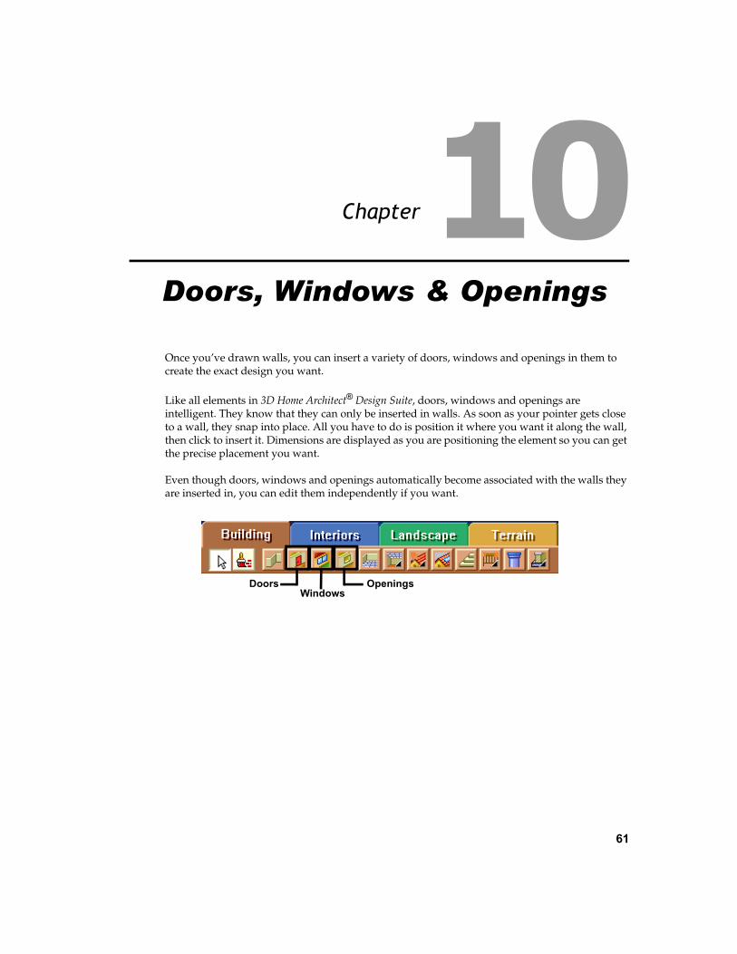
61
Chapter
Once you’ve drawn walls, you can insert a variety of doors, windows and openings in them to create the exact design you want.
Like all elements in 3D Home Architect® Design Suite, doors, windows and openings are intelligent. They know that they can only be inserted in walls. As soon as your pointer gets close to a wall, they snap into place. All you have to do is position it where you want it along the wall, then click to insert it. Dimensions are displayed as you are positioning the element so you can get the precise placement you want.
Even though doors, windows and openings automatically become associated with the walls they are inserted in, you can edit them independently if you want.
OpeningsDoorsWindows
Doors, Windows & Openings

Chapter 10 Doors, Windows & Openings
62 3D Home Architect® Design Suite Deluxe 6
Inserting DoorsThe catalog contains a wide variety of doors for you to insert, including hinged, bi-fold, pocket, sliding glass and garage doors. You can point and click to insert a door, or offset the door a specific distance from the end of a wall.
Doors are inserted at floor level. You can raise or lower a door after you have inserted it if you need to.
To insert a door:1. Make sure the location you want to insert
doors on is the current location in the building locations drop box.
2. Select Insert > Doors, or click the Doors button on the Building toolbar.
3. In the catalog, select the door you want to insert.
4. If you want to offset the door a specific distance from the end of the wall, right-click and select Enter insertion offset.
Enter the offset distance in the Enter insertion offset dialog, then click OK.
5. Position the door in the receiving wall. If you are using an insertion offset, position the door close to the end you want to offset it from. The door will snap inside the wall. Dimensions are displayed that show you the distance on either side of the door.
6. With your door positioned where you want it, click to insert it.
7. Right-click and select Finish.
Editing Door TypesDoor types include hinged, bi-fold, pocket, face slider, track slider, fold-up, tilt, and roller. You can edit a door’s type on the door’s Basic property page.
To edit a door type:1. Select the door whose properties you want to
change.
2. Right-click and select Properties, or select Edit > Modify Elements > Properties.
3. In the Doors dialog, select the Basic tab.
4. In the Type area, click on the desired door type to select it.
5. Click OK.
Editing the Size and Shape of a DoorYou can edit the shape of a door, its height and width, and swing type.
To edit the size of a door:1. Select the door whose properties you want to
change.
2. Right-click and select Properties, or select Edit > Modify Elements > Properties.

Editing a Door’s Sidelites and Highlites
User’s Guide 63
10
3. In the Doors dialog, select the Basic tab.
4. Edit the shape and dimensions as desired. Clicking a dimension marked with an alphabetical character (a, b, c, etc.) highlights the corresponding dimension in the door graphic, and vice versa.
Shape. Choose from Rectangular, Arched or Apexed.
Width. The width of the door leaf.
Height. The height of the door leaf.
Swing Type. Choose from Left, Right or Dou-ble. A door with a left door swing will have its hinges on the right.
3D % Open. How much the door is shown swung open in 3D view. By default, doors are shown closed in 3D view.
2D % Open. How much the door is swung open in 2D plan view.
Editing a Door’s Sidelites and HighlitesA sidelite is a fixed glass panel set on one or both sides of a door (usually an entry door). A highlite is a fixed glass panel above a door. You can create a custom configuration of sidelites and/or highlights for a door.
To display lites on a door:1. Select the door.
2. Right-click and select Properties, or select Edit > Modify Elements > Properties.
3. In the Doors dialog, select the Basic tab.
4. To display a highlite over the door, enable the Display Highlite check box.
5. To display a sidelite on the left side of the door, enable the Display Left Sidelite check box.
6. To display a sidelite on the right side of the door, enable the Display Right Sidelite check box.
To edit sidelites and highlites:1. Select the door whose properties you want to
change.
2. Right-click and select Properties, or select Edit > Modify Elements > Properties.
3. In the Doors dialog, select the Lites tab.
4. In the Type window, select the lite you want to specify settings for. Note that the lite must be enabled on the Basic property page before it can be edited.
5. To select a specific window type for the currently selected lite, click on the appropriate graphic in the Type area.
6. Edit the dimensions of the lite in the Properties area if desired. Clicking a dimension marked with an alphabetical character (a, b, c, etc.) highlights the

Chapter 10 Doors, Windows & Openings
64 3D Home Architect® Design Suite Deluxe 6
corresponding dimension in the sidelite/highlite graphic, and vice versa.
Shape. Choose from Rectangle, Arched or Trapezoid.
(highlite) Adjust Width. Selecting Opening adjusts the width of the highlite to match the width of the opening (including any sidelites). Selecting Door adjusts the width of the highlite to match the width of the door (excluding any sidelites). Selecting User Defined lets you specify a precise width for the highlite in the Width edit box.
Width. The total width of the lite.
(sidelites) Adjust Height to Door. Automati-cally adjusts the height of a sidelite to match the height of the door.
Height. The overall height of the lite.
# of Horizontal Panels. The number of pan-els across the lite. If you specify more than one panel, vertical dividers are added inside the lite’s frame.
# of Vertical Panels. The number of panels running vertically along the lite. If you spec-ify more than one panel, horizontal dividers are added inside the lite’s frame.
# of Horizontal Panes. The number of panes of glass across the lite.
# of Vertical Panes. The number of panes of glass running vertically along the lite.
7. Click OK.
Editing a Door LeafYou can choose from a variety of door leaf types and change the thickness of the leaf.
To edit a door’s leaf:1. Select the door whose properties you want to
change.
2. Right-click and select Properties, or select Edit > Modify Elements > Properties.
3. In the Doors dialog, select the Leaf tab.
4. In the Type area, click on the leaf type you want.
5. If you want to change the thickness of the leaf, enter the thickness in the Leaf Depth edit box.
6. Each door leaf type has its own set of dimensions that you can define. These dimensions vary according to how many panels the leaf has. Clicking a dimension marked with an alphabetical character (a, b, c, etc.) highlights the corresponding dimension in the door leaf graphic, and vice versa.
7. Click OK.
Editing Door DetailsYou can specify precise dimensions and offsets for the door frame, sash, mullions and transoms.
To edit door details:1. Select the door whose properties you want to
change.
2. Right-click and select Properties, or select Edit > Modify Elements > Properties.

Flipping a Door
User’s Guide 65
10
3. In the Doors dialog, select the Details tab.
4. Edit the dimensions as desired. They are described below.
Frame
Depth. The depth of the frame members as seen from an overhead view.
Width. The width of the frame members as seen from an overhead view.
Offset. The offset of the door frame from the wall face.
Sash
Depth. The depth of sash members (sidelite/highlite frame) as seen from an overhead view.
Width. The width of sash members as seen from an overhead view.
Offset. The offset of the sash from the front of the door frame, i.e. how far back it sits in the door frame.
Mullion
Vertical Separation. If a lite has two or more panels running across it, this adds vertical dividers between the panels.
Horizontal Separation. If a lite has two or more stacked panels, this adds horizontal dividers between them.
Depth. The front-to-back thickness of the mullion as seen from an overhead view.
Width. The width (left-to-right distance) of the mullion as seen from an overhead view.
Transom
Depth. The front-to-back thickness of the transom member as seen from an overhead view. The transom is the member between the door and the sidelite or highlite frame.
Width. The width of the transom as seen from an overhead view.
5. Click OK.
Flipping a DoorYou can use the Flip Opening tool to flip an entire door around. If the door originally opened out, it now opens in; if it was hinged on the left, it is now hinged on the right (and vice versa).
To flip a door:1. Click the door to select it.
2. Right-click in the drawing area and select Flip Opening, or select Edit > Modify Elements > Flip Opening.
Flipping a Door SwingUse the Flip Swing tool to flip only the swing of a door. The door will be hinged on the opposite side, but it will still open in the same direction, either in or out.
To flip a door swing:1. Click the door to select it.
2. Right-click in the drawing area and select Flip Swing, or select Edit > Modify Elements > Flip Swing.
Moving a DoorYou can move a door by clicking and dragging it inside the wall, or by editing the dynamic dimensions on either side of the door.
To move a door by clicking and dragging:1. Click on the door to select it.
2. Click and drag the door to move it, then release your mouse button.

Chapter 10 Doors, Windows & Openings
66 3D Home Architect® Design Suite Deluxe 6
To move a door by editing dimensions:1. Click on the door. Dimensions appear on
either side of the door.
2. Click on the dimension you want to edit.
3. In the Edit Dimension dialog, enter the new value, then press Enter or click OK. The door position updates automatically.
Raising or Lowering a DoorYou can raise or lower a door in a wall using the Elevate tool on the door’s right-click menu. You may, for example, want to lower your garage door if your ground floor sits above the ground.
To raise or lower a door:1. Select the door whose elevation you want to
edit.
2. Right-click and select Elevate, or select Edit > Modify Elements > Elevate.
The value currently shown in the Elevate dialog is the current elevation of the door above or below the floor level.
3. In the Elevate dialog, specify the desired elevation of the door base above the floor. You can enter a negative value to move the door down.
4. Click OK.
Deleting a DoorYou can delete a door with a couple of mouse clicks.
To delete a door:1. Select the door to delete. To select multiple
doors, use Shift+click.
2. Click the Delete button on your keyboard, or right-click and select Delete, or select Edit > Modify Elements > Delete.
Inserting WindowsThe catalog contains a wide variety of windows for you to insert, including fixed, casement, double casement, hopper, awning, sliding, double-hung, single-hung, bay, bow and louvered windows.
You can point and click to insert a window, or offset the window a specific distance from the end of a wall.
Windows are inserted at the Head Height defined for the building location you insert the window on. You can raise or lower a window after you have inserted it if you need to.
Note: If you want to insert a skylight, see Inserting Skylights on page 104.
To insert a window:1. Make sure the location you want to insert
windows on is the current location in the building locations drop box.
2. Select Insert > Windows, or click the Windows button on the Building toolbar.
3. In the catalog, select the window you want to insert.
4. If you want to offset the window a specific distance from the end of

Editing Window Types
User’s Guide 67
10
the wall, right-click and select Enter insertion offset.
Enter the offset distance in the Enter inser-tion offset dialog, then click OK.
5. Position the window in the receiving wall. If you are using an insertion offset, position the window close to the end you want to offset it from. The window will snap inside the wall. Dimensions are displayed that show you the distance on either side of the window.
6. With your window positioned where you want it, click to insert it.
7. Right-click and select Finish.
Editing Window TypesWindow types include fixed, casement, hung, sliding, awning, hopper, vent, bay, bow and louvre. You can edit a window’s type on the window’s Basic property page.
To edit a window type:1. Select the window whose properties you
want to change.
2. Right-click and select Properties, or select Edit > Modify Elements > Properties.
3. In the Windows dialog, select the Basic tab.
4. In the Type area, click on the desired window type to select it.
5. Click OK.
Editing a Window’s Size PropertiesYou can edit the height and width of a window. You can also control the number of horizontal and vertical panes in the window. Some window types have additional properties that define their geometry.
To edit the size of a window:1. Select the window whose properties you
want to change.
2. Right-click and select Properties, or select Edit > Modify Elements > Properties.
3. In the Windows dialog, select the Basic tab.
4. Edit the dimensions as desired. Most windows have the common dimensions listed below. Some have additional settings to define their geometry. Clicking a dimension marked with an alphabetical character (a, b, c, etc.) highlights the corresponding dimension in the window graphic, and vice versa.
Window Width. The width of the window, not including the frame.
Window Height. The height of the window.
# of Horizontal Panels. The number of win-dow panels running horizontally across the window frame. If you specify more than one

Chapter 10 Doors, Windows & Openings
68 3D Home Architect® Design Suite Deluxe 6
panel, vertical dividers are added inside the window frame.
# of Vertical Panels. The number of window panels running vertically along the window frame. If you specify more than one panel, horizontal dividers are added inside the win-dow frame.
# of Horizontal Panes. The number of panes of glass across each window panel.
# of Vertical Panes. The number of panes of glass running vertically along each window panel.
5. Click OK.
Editing a Window’s Sidelites, Highlites and LowlitesA sidelite is a fixed glass panel set on one or both sides of a window. A highlite is a glass panel above a window. A lowlite is a glass panel below a window. You can create a custom configuration of sidelites, highlites and lowlites for a window.
To display lites on a window:1. Select the window.
2. Right-click and select Properties, or select Edit > Modify Elements > Properties.
3. In the Windows dialog, select the Basic tab.
4. To display a highlite over the window, enable the Display Highlite check box.
5. To display a lowlite under the window, enable the Display Lowlite check box.
6. To display a sidelite on the left side of the window, enable the Display Left Sidelite check box.
7. To display a sidelite on the right side of the window, enable the Display Right Sidelite check box.
8. Click OK.
To edit a window’s lites:1. Select the window whose properties you
want to change.
2. Right-click and select Properties, or select Edit > Modify Elements > Properties.
3. In the Windows dialog, select the Lites tab.
4. To display a highlite, sidelite or lowlite, check the appropriate box in the Type area (Highlite, Lowlite, Sidelite - left, Sidelite - right). You can select as many as you want.
5. In the Type window, select the lite you want to specify settings for.
6. To select a specific window type for the currently selected lite, click on the appropriate graphic in the Type area.
7. Edit the dimensions of the lite in the Properties area if desired. Clicking a dimension marked with an alphabetical character (a, b, c, etc.) highlights the corresponding dimension in the sidelite/highlite graphic, and vice versa.
Shape. Choose from Rectangle, Arched or Trapezoid.
(highlite/lowlite) Adjust Width. Selecting Opening adjusts the width of the highlite to match the width of the opening (including any sidelites). Selecting Window adjusts the width of the highlite to match the width of the window (excluding any sidelites). Select-ing User Defined lets you specify a precise width for the highlite/lowlite in the Width edit box.
Width. The total width of the lite.

Editing Window Details
User’s Guide 69
10
(sidelites) Adjust Height to Window. Auto-matically adjusts the height of a sidelite to match the height of the window.
Height. The overall height of the lite.
# of Horizontal Panels. The number of pan-els across the lite. If you specify more than one panel, vertical dividers are added inside the lite’s frame.
# of Vertical Panels. The number of panels running vertically along the lite. If you spec-ify more than one panel, horizontal dividers are added inside the lite’s frame.
# of Horizontal Panes. The number of panes of glass across the lite.
# of Vertical Panes. The number of panes of glass running vertically along the lite.
8. Click OK.
Editing Window DetailsYou can specify precise dimensions and offsets for the window frame, sash, mullions and transoms.
To edit window details:1. Select the window whose properties you
want to change.
2. Right-click and select Properties, or select Edit > Modify Elements > Properties.
3. In the Windows dialog, select the Details tab.
4. Edit the dimensions as desired. They are described below.
Frame
Depth. The depth of the frame members as seen from an overhead view.
Width. The width of the frame members as seen from an overhead view.
Offset. The offset of the window frame from the wall face.
Sash
Depth. The depth of sash members (sidelite/highlite/lowlite frame) as seen from an over-head view.
Width. The width of sash members as seen from an overhead view.
Offset. The offset of the sash from the front of the window frame, i.e. how far back it sits in the window frame.
Post (for Bays and Bows)
Depth: The thickness of posts in bay and bow windows.
Width: The width of posts in bay and bow windows.
Mullion
Vertical Separation. If a lite has two or more panels running across it, this adds vertical dividers between the panels.
Horizontal Separation. If a lite has two or more stacked panels, this adds horizontal dividers between them.
Depth. The front-to-back thickness of the mullion as seen from an overhead view.
Width. The width (left-to-right distance) of the mullion as seen from an overhead view.
Transom (for Lites)
Depth. The front-to-back thickness of the transom member as seen from an overhead view. The transom is the member between the window and the sidelite, highlite or lowlite frame.
Width. The width of the transom as seen from an overhead view.
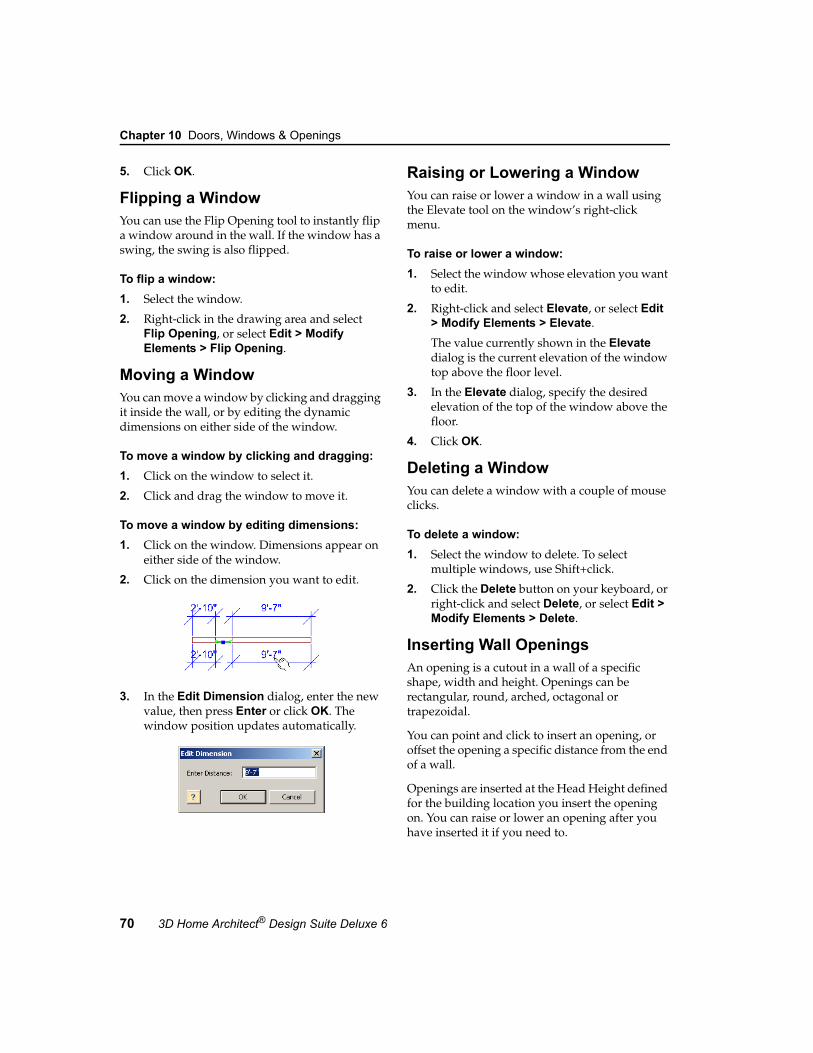
Chapter 10 Doors, Windows & Openings
70 3D Home Architect® Design Suite Deluxe 6
5. Click OK.
Flipping a WindowYou can use the Flip Opening tool to instantly flip a window around in the wall. If the window has a swing, the swing is also flipped.
To flip a window:1. Select the window.
2. Right-click in the drawing area and select Flip Opening, or select Edit > Modify Elements > Flip Opening.
Moving a WindowYou can move a window by clicking and dragging it inside the wall, or by editing the dynamic dimensions on either side of the window.
To move a window by clicking and dragging:1. Click on the window to select it.
2. Click and drag the window to move it.
To move a window by editing dimensions:1. Click on the window. Dimensions appear on
either side of the window.
2. Click on the dimension you want to edit.
3. In the Edit Dimension dialog, enter the new value, then press Enter or click OK. The window position updates automatically.
Raising or Lowering a WindowYou can raise or lower a window in a wall using the Elevate tool on the window’s right-click menu.
To raise or lower a window:1. Select the window whose elevation you want
to edit.
2. Right-click and select Elevate, or select Edit > Modify Elements > Elevate.
The value currently shown in the Elevate dialog is the current elevation of the window top above the floor level.
3. In the Elevate dialog, specify the desired elevation of the top of the window above the floor.
4. Click OK.
Deleting a WindowYou can delete a window with a couple of mouse clicks.
To delete a window:1. Select the window to delete. To select
multiple windows, use Shift+click.
2. Click the Delete button on your keyboard, or right-click and select Delete, or select Edit > Modify Elements > Delete.
Inserting Wall OpeningsAn opening is a cutout in a wall of a specific shape, width and height. Openings can be rectangular, round, arched, octagonal or trapezoidal.
You can point and click to insert an opening, or offset the opening a specific distance from the end of a wall.
Openings are inserted at the Head Height defined for the building location you insert the opening on. You can raise or lower an opening after you have inserted it if you need to.

Editing the Shape of a Wall Opening
User’s Guide 71
10
To insert an opening:1. Make sure the location you want to insert
openings on is the current location in the building locations drop box.
2. Select Insert > Openings, or click the Openings button on the Building toolbar.
3. In the catalog, select the opening you want to insert.
4. If you want to offset the opening a specific distance from the end of the wall, right-click and select Enter insertion offset.
Enter the offset distance in the Enter inser-tion offset dialog, then click OK.
5. Position the opening in the receiving wall. If you are using an insertion offset, position the opening close to the end you want to offset it from. The opening will snap inside the wall. Dimensions are displayed that show you the distance on either side of the opening.
6. With your opening positioned where you want it, click to insert it.
7. Right-click and select Finish.
Editing the Shape of a Wall OpeningOpenings can be rectangular, round, arched, octagonal or trapezoidal.
To change the shape a wall opening:1. Select the opening whose properties you
want to change.
2. Right-click and select Properties, or select Edit > Modify Elements > Properties.
3. In the Type area, click on the shape you want.
4. Click OK.
Editing the Size of a Wall OpeningYou can edit the dimensions of a wall opening by changing the properties on the opening’s Basic property page.
To edit the size of a wall opening:1. Select the opening whose properties you
want to change.
2. Right-click and select Properties, or select Edit > Modify Elements > Properties.
3. In the Properties area, edit the dimensions of the opening. Dimensions vary according to the shape of the opening.
4. Click OK.
Tip: If you want the bottom of your opening to be level with the floor, change the height of opening to match the Head Height of the building location it is inserted on. Alternatively you can lower the opening using the Elevate tool.
Moving a Wall OpeningYou can move a wall opening by clicking and dragging it inside the wall, or by editing the dynamic dimensions on either side of the opening.
To move an opening by clicking and dragging:1. Click on the opening to select it.
2. Click and drag the opening to move it.
To move an opening by editing dimensions:1. Click on the opening. Dimensions appear on
either side of the opening.

Chapter 10 Doors, Windows & Openings
72 3D Home Architect® Design Suite Deluxe 6
2. Click on the dimension you want to edit.
3. In the Edit Dimension dialog, enter the new value, then press Enter or click OK. The opening position updates automatically.
Raising or Lowering a Wall OpeningYou can raise or lower an opening in a wall using the Elevate tool on the opening’s right-click menu.
To raise or lower a wall opening:1. Select the opening whose elevation you want
to edit.
2. Right-click and select Elevate, or select Edit > Modify Elements > Elevate.
The value currently shown in the Elevate dialog is the current elevation of the opening top above the floor level.
3. In the Elevate dialog, specify the desired elevation of the top of the opening above the floor.
4. Click OK.
Deleting a Wall OpeningYou can delete a wall opening with a couple of mouse clicks.
To delete an opening:1. Select the opening to delete. To select
multiple openings, use Shift+click.
2. Click the Delete button on your keyboard, or right-click and select Delete, or select Edit > Modify Elements > Delete.

73
Chapter
A floor is inserted automatically when you connect three or more walls to create a closed wall layout. When you insert interior walls, the floor is split as new rooms are created. If you want different flooring types in different rooms, you can use the Materials Paintbrush to quickly apply different types of carpet, tiles, wood flooring, vinyl flooring, linoleum, or concrete to individual floors.
Ceilings are not created automatically unless you turn on the Insert Ceilings Automatically option in your program settings before drawing walls. Alternatively you can point and click to insert ceilings using one of the handy Ceiling tools.
CeilingsDefine Floors
Floors & Ceilings

Chapter 11 Floors & Ceilings
74 3D Home Architect® Design Suite Deluxe 6
How Floors are CreatedA floor is automatically inserted throughout your model when you connect three or more walls to create a closed exterior wall layout.
The material applied to the floor depends on the house style you selected when using the House Builder Wizard. If you created your model from scratch, a nylon carpet was applied.
When you draw interior walls, the floor is split into individual floors as new rooms are created provided the room’s walls are all connected. You can also manually split any floor surface using the Define Floors tool.
Floors cannot be selected in 2D plan view. They can only be selected in 3D view. The only exception are floor edges that have been defined using the Define Floors tool. Such edges are marked with a dashed line in 2D view, and can be moved if necessary.
Floors are directly associated with the walls that contain them. If you stretch your wall layout, the floor stretches with it. If you open up your wall layout by deleting a wall, the floor will be deleted. You cannot re-insert a floor manually.
Tip: For projects in which you plan to use the House Builder Wizard, you can change the default floor type by editing the House Builder Wizard element configuration before running the Wizard. See Creating a Custom House Builder Wizard Configuration on page 376. If you plan to create a model from scratch, you can change the default floor type by selecting the desired floor type in the Catalog Manager before creating your wall layout. See Using the Catalog Manager on page 334.
Defining Individual Floor Areas As you draw interior walls, the floor is split into individual floors as new rooms are created provided the rooms are completely enclosed by walls. You can manually split a floor if you want. You may, for example, want to create two different floor areas in one room. You can also use the Define Floors tool to define an opening in your floor. Floor edges defined with the Define
Floors tool can be moved to increase or decrease the size of the individual floor area. They can also be deleted if necessary.
To define individual floor areas:1. Select Insert > Define Floors, or click
the Define Floors button on the Building toolbar.
2. Select points to define the split line.
Note that the start point and end point of the line must be on an existing floor edge, although intermediate points are permitted anywhere on the floor surface (if you are cre-ating a custom floor shape, for example).
3. Right-click and select Finish.
To move a defined floor edge:1. Click on the dashed floor edge in 2D plan
view. Blue grab handles are displayed along the line.
2. Hover your pointer over the center grab handle, then click and drag to move the line.
3. Release your mouse button.
Raising or Lowering a FloorYou can raise or lower a floor using the Elevate tool.
To raise or lower a floor:1. Select the floor in 3D.
2. Right-click and select Elevate, or select Edit > Modify Elements > Elevate.
3. In the Elevate dialog, specify the desired elevation of the floor above the floor level defined for the current building location.
4. Click OK.
x
x

Editing the Thickness of a Floor
User’s Guide 75
11
Editing the Thickness of a FloorYou can edit the thickness of a floor on its Basic property page.
To edit the thickness of a floor:1. Select the floor in 3D.
2. Right-click and select Properties, or select Edit > Modify Elements > Properties.
3. Edit the value in the Thickness edit box on the Basic page.
4. Click OK.
Applying Different Materials to FloorsYou can use the Materials Paintbrush to quickly apply different types of materials to floors, such as different colors or patterns of carpet, tile or linoleum.
To apply a material to a floor:1. Display your model in 3D view and make
sure the floor is visible in the view. You may need to use the View Filter to hide the roof and ceilings.
2. Select Edit > Materials Paintbrush, or click the Materials Paintbrush button on any tabbed toolbar.
3. In the catalog panel, select the material you want to apply. Categories that contain flooring include Wood, Concrete, Carpet, Tile and Linoleum.
4. Click on the floor surface you want to apply the material to. The material is immediately applied. You can continue applying the material to other floor surfaces, or select another material in the catalog.
5. Right-click and select Finish.
Inserting Openings in FloorsYou can insert an opening of any shape and size in a floor. You may need to do this to accommodate a staircase.
To insert an opening in a floor:1. Select Insert > Define Floors, or click
the Define Floors button on the Building toolbar.
2. Select points to define the outline of the opening, ensuring the outline is a closed shape.
3. Right-click and select Finish. An outline is created on the floor surface. You can stretch, move and curve the opening if necessary to get the exact size and shape you want. Note that you cannot edit the size, shape or position of the opening later, so make sure it’s correct before proceeding.
4. Go into 3D view and make sure the floor is visible and accessible.
5. Click in the center of the outline you drew to select the outline.
6. Press the Delete key on your keyboard, or right-click and select Delete, or select Edit > Modify Elements > Delete.
Deleting a FloorYou can delete a floor while in 3D view.
Warning: There is no method of inserting floors manually. They can only be created while drawing walls.
To delete a floor:1. Select the floor in 3D.
2. Press the Delete key on your keyboard, or right-click and select Delete, or select Edit > Modify Elements > Delete.
How Ceilings Are CreatedIf you turn on the Insert Ceilings Automatically feature in your Program Settings before drawing walls, a ceiling is automatically created when you connect three or more walls to form a closed wall layout.
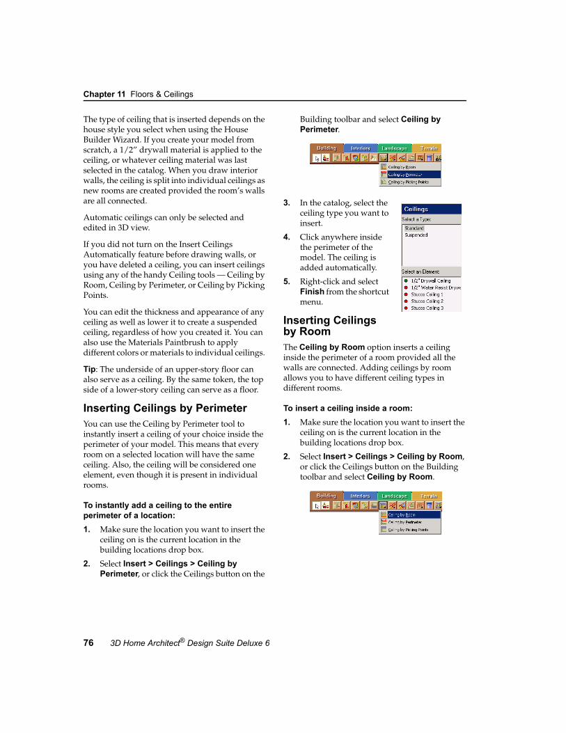
Chapter 11 Floors & Ceilings
76 3D Home Architect® Design Suite Deluxe 6
The type of ceiling that is inserted depends on the house style you select when using the House Builder Wizard. If you create your model from scratch, a 1/2” drywall material is applied to the ceiling, or whatever ceiling material was last selected in the catalog. When you draw interior walls, the ceiling is split into individual ceilings as new rooms are created provided the room’s walls are all connected.
Automatic ceilings can only be selected and edited in 3D view.
If you did not turn on the Insert Ceilings Automatically feature before drawing walls, or you have deleted a ceiling, you can insert ceilings using any of the handy Ceiling tools — Ceiling by Room, Ceiling by Perimeter, or Ceiling by Picking Points.
You can edit the thickness and appearance of any ceiling as well as lower it to create a suspended ceiling, regardless of how you created it. You can also use the Materials Paintbrush to apply different colors or materials to individual ceilings.
Tip: The underside of an upper-story floor can also serve as a ceiling. By the same token, the top side of a lower-story ceiling can serve as a floor.
Inserting Ceilings by PerimeterYou can use the Ceiling by Perimeter tool to instantly insert a ceiling of your choice inside the perimeter of your model. This means that every room on a selected location will have the same ceiling. Also, the ceiling will be considered one element, even though it is present in individual rooms.
To instantly add a ceiling to the entire perimeter of a location:1. Make sure the location you want to insert the
ceiling on is the current location in the building locations drop box.
2. Select Insert > Ceilings > Ceiling by Perimeter, or click the Ceilings button on the
Building toolbar and select Ceiling by Perimeter.
3. In the catalog, select the ceiling type you want to insert.
4. Click anywhere inside the perimeter of the model. The ceiling is added automatically.
5. Right-click and select Finish from the shortcut menu.
Inserting Ceilings by RoomThe Ceiling by Room option inserts a ceiling inside the perimeter of a room provided all the walls are connected. Adding ceilings by room allows you to have different ceiling types in different rooms.
To insert a ceiling inside a room:1. Make sure the location you want to insert the
ceiling on is the current location in the building locations drop box.
2. Select Insert > Ceilings > Ceiling by Room, or click the Ceilings button on the Building toolbar and select Ceiling by Room.

Inserting a Ceiling by Picking Points
User’s Guide 77
11
3. In the catalog, select the ceiling type you want to insert.
4. Click inside the room that you want to add the ceiling to. The ceiling is added automatically. (If you want, you can continue adding ceilings to other rooms.)
5. Right-click and select Finish from the shortcut menu.
Inserting a Ceiling by Picking PointsUsing the Ceiling by Picking Points tool you can insert a ceiling by picking points to define the ceiling’s outline. This lets you create a ceiling of any shape and size, anywhere in the drawing area.
To create a ceiling by picking points:1. Make sure the location you want to insert the
ceiling on is the current location in the building locations drop box.
2. Select Insert > Ceilings > Ceiling by Picking Points, or click the Ceilings button on the Building toolbar and select Ceiling by Picking Points.
3. In the catalog, select the ceiling type you want to insert.
4. Select a start point for the ceiling outline.
5. Continue selecting points until the outline is defined. (You do not have to select the start point again because the
last point you pick is always closed back to the start point.)
6. Right-click and select Finish.
Raising or Lowering a CeilingYou can change the height of a ceiling using the Elevate tool.
To raise or lower a ceiling:1. Select the ceiling you want to raise or lower
by clicking on the edge of it. If the ceiling was created automatically when drawing walls, you need to select it in 3D view.
2. Right-click and select Elevate, or select Edit > Modify Elements > Elevate.
The current value in the Elevate dialog is the current elevation of the ceiling above the floor level.
3. In the Elevate dialog, specify the height you want the ceiling to sit at above the floor.
4. Click OK.
Curving a Ceiling EdgeYou can curve a ceiling edge using the Curve tool. Once the tool is active, you can click and drag the edge to curve it, or select a point to curve to.
To curve a ceiling edge by clicking and dragging:1. Click on the edge you want to curve.
2. Right-click and select Curve, or select Edit > Modify Elements > Curve.
3. Click and drag the ceiling edge to the desired curve.
4. Release your mouse button.
To curve a ceiling edge to a selected point:1. Click on the ceiling edge you want to curve.
2. Right-click in and select Curve, or select Edit > Modify Elements > Curve.
3. Select the point you want to curve to. The ceiling edge automatically curves to the point.
4. Click to finish.

Chapter 11 Floors & Ceilings
78 3D Home Architect® Design Suite Deluxe 6
Inserting Openings in Automatic CeilingsIf you opted to insert a ceiling automatically before drawing walls, you can create a custom opening in the automatic ceiling using the Define Floors and Delete tools.
To insert an opening in an automatic ceiling:1. In 2D plan view, select Insert > Define
Floors, or click the Define Floors button on the Building toolbar.
2. Select points to define the outline of the opening, ensuring the outline is a closed shape.
3. Right-click and select Finish. An outline is created on both the floor and ceiling of the current location. If necessary you can move, stretch or curve edges to get the exact size and shape you want. Note that you cannot edit the size, shape or position of the opening later, so make sure it’s correct before proceeding.
4. Go into 3D view and make sure the ceiling is visible.
5. Click in the center of the outline you drew to select the outline.
6. Press the Delete key on your keyboard, or right-click and select Delete, or select Edit > Modify Elements > Delete.
Inserting Openings in Manually Inserted CeilingsIf you used a Ceiling tool to insert a ceiling, you can insert a custom opening in it of virtually any shape and size using the Cut Opening tool.
You create the opening by picking points to define its outline.
To insert an opening in a ceiling:1. Select the ceiling by clicking on one of its
edges.
2. Right-click and select Cut Opening, or select Edit > Modify Elements > Cut Opening.
3. Select a start point for the opening.
4. Continue selecting points to define the opening. As you select points, the opening is created. The last point picked is always connected back to the start point to form a closed shape, so you don’t have to select the start point again.
5. Right-click and select Finish.
Note: You cannot insert openings this way in ceilings that were created automatically when drawing walls.
Resizing a Ceiling OpeningIf you created a ceiling opening in a manually inserted ceiling, you can resize the opening by clicking and dragging one of its edges.
Note: You cannot edit an opening created in an automatic ceiling.
To stretch a ceiling opening:1. In 2D plan view, click on the opening edge
you want to move. The entire opening is highlighted, and a blue grab handle appears at the center of the opening edge you selected.
2. Hover your pointer over the center grab handle to display the Move cursor.
Grab handle

Curving a Ceiling Opening Edge
User’s Guide 79
11
3. Click and drag in the direction you want to stretch.
4. When the opening is the correct size, release your mouse button.
Tip: You can also reshape a ceiling opening by clicking and dragging its corner grab handles.
Curving a Ceiling Opening EdgeYou can curve an opening edge in a manually inserted ceiling using the Curve tool. Once the tool is active, you can click and drag the opening edge to curve it, or select a point to curve to.
Note: You cannot edit an opening created in an automatic ceiling.
To curve an opening edge by clicking and dragging:1. Click on the opening edge you want to curve.
2. Right-click and select Curve, or select Edit > Modify Elements > Curve.
3. Click and drag the opening edge to the desired curve.
4. Release your mouse button.
To curve an opening edge to a selected point:1. Click on the opening edge you want to curve.
2. Right-click in and select Curve, or select Edit > Modify Elements > Curve.
3. Select the point you want to curve to. The opening edge automatically curves to the point.
4. Click to finish.
Removing Ceiling OpeningsYou can remove an opening from a manually inserted ceiling by selecting all sides of the opening, then clicking and dragging it away from the ceiling.
Note: You cannot remove an opening using Delete. Also, you cannot remove an opening created in an automatic ceiling.
To remove a ceiling opening:1. Click on one of the opening’s edges.
2. Shift+click to select the remaining sides.
3. Hover your pointer over one of the grab handles to display the Move cursor.
4. Click and drag the opening off the ceiling surface until it disappears.
Applying Different Colors and Materials to CeilingsYou can use the Materials Paintbrush to quickly apply different colors or materials to ceilings. The paintbrush intelligently applies the material to the underside of the ceiling, even if you select the top side of the ceiling.
To apply a material to a ceiling:1. Display your model in 3D view and make
sure the ceiling is visible in the view. You may need to use the View Filter to hide the roof.
2. Select Edit > Materials Paintbrush, or click the Materials Paintbrush button on any tabbed toolbar.

Chapter 11 Floors & Ceilings
80 3D Home Architect® Design Suite Deluxe 6
3. In the catalog panel, select the material you want to apply. Paint colors are located in the Paint category, and Stucco and Drywall can be found in the Finishes category.
4. Click on the ceiling you want to apply the material to. The material is immediately applied to the underside of the ceiling. You can continue applying the material to other ceiling surfaces, or select another material in the catalog.
5. Right-click and select Finish.
Deleting a CeilingYou can delete a ceiling in a couple of easy steps.
To delete a ceiling:1. Select the ceiling. If the ceiling was created
automatically when drawing walls, you need to select it in 3D view.
2. Press the Delete key on your keyboard, right-click and select Delete, or select Edit > Modify Elements > Delete.

81
Chapter
If your design has more than one floor, you’ll want to insert a staircase. The catalog contains a variety of stair and ramp styles, including straight, spiral, fold-back, L-shaped, L-winder. There are even stairs specifically for decks and porches. You can edit the composition and dimensions of each component in your staircase to create the exact look you want.
Stairs and ramps are inserted as solid objects with point-and-click simplicity. Just select the staircase or ramp you want to insert in the catalog, then click to insert it in your model.
The catalog also contains an excellent selection of railing types. A railing can be just a handrail, or a balustrade with posts, top/bottom rails and newels. You can insert railings on a staircase automatically. You can choose to put it on both sides, the left side, the right side, or the center. You can also draw a horizontal railing by picking points.
RailingsStairs/Ramps
Stairs, Ramps & Railings

Chapter 12 Stairs, Ramps & Railings
82 3D Home Architect® Design Suite Deluxe 6
Inserting Stairs and RampsYou can insert a staircase or ramp with a single mouse click. If you place the staircase near a wall, the staircase will automatically snap to the wall. Once you have inserted a staircase, you can edit its size, style and geometry.
To insert a staircase or ramp:1. In the building locations drop box, select the
location where you want to insert the base of the staircase.
2. Select Insert > Stairs/Ramps, or click the Stairs/Ramps button on the Building toolbar.
3. In the catalog, select the staircase or ramp you want to insert.
4. Position the staircase and click to insert it.
5. Right-click and select Finish.
Parts of a Staircase
Editing Stair Size PropertiesBy default, most stairs (except porch stairs) have an overall height of 9’ and have 18 steps. You can edit the general dimensions of a staircase, such as height, width, and number of steps.
To edit stair size properties:1. Select the staircase whose stair properties
you want to edit.
2. Right-click and select Properties, or select Edit > Modify Elements > Properties.
3. In the Stairs/Ramps dialog, edit the dimensions in the Properties window.
Overall Height. The vertical distance from the base of the staircase to the top of the stair-case. Generally this is the distance from one floor to the next.
Total Steps. The total number of steps in the staircase including all treads and landings. This value is controlled by the Overall Height and Riser Maximum, so you can only go so high or so low when specifying the total number of steps.
Riser Height. The distance from the top of one tread to the top of the next tread. The riser height adjusts if you edit the Overall Height or Total Steps, making this a read-only value.
Stringer
Nosing
Riser
Tread

Editing a Staircase Layout
User’s Guide 83
12
Tread Run. The width of a step from the nose of the step to the riser of the next step.
Riser Maximum. The maximum height allowed for risers. The riser height adjusts when you change the Overall Height or Total Steps variables.
Show Riser. Inserts vertical boards under the treads. If turned off, the stairs are open under the treads.
Editing a Staircase LayoutYou can choose from a multitude of preset staircase layouts and edit the dimensions of individual segments to suit your needs.
To edit a staircase layout:1. Select the staircase whose stair properties
you want to edit.
2. Right-click and select Properties, or select Edit > Modify Elements > Properties.
3. In the Stairs/Ramps dialog, select the Layout tab.
4. To change the layout of the staircase, make a selection from the Preset Layouts drop box, or click the graphic to display the available layouts and select the one you want.
5. To edit the dimensions of a particular segment, select the segment in the Layout Segments window. For example, an L-shaped staircase will have three segments: Stair 1, Landing 2 and Stair 3. The Stair 1 segment is the lower flight of stairs, Landing 2 is the central landing between the two flights, and Stair 3 is the upper flight of stairs.
6. Different layouts will have different parameters. Common ones are described below. Clicking a dimension marked with an alphabetical character (a, b, c, etc.) highlights the corresponding dimension in the stair graphic, and vice versa.
Stair Segments
Number of Steps. The number of steps in the flight.
Position Offset. Shifts the base of the stair-case left or right from the center line. A posi-tive value shifts it right, a negative value shifts it left. If the Upper Offset is set to 0, the entire staircase is moved.
Lower Width. The width of the bottom step.
Upper Width. The width of the top step.
Upper Offset. Shifts the top of the stair seg-ment left or right to create an angled flight. A positive value shifts it right, a negative value shifts it left.
Landing Connection. Choose from Front, Bottom or Under to determine how the stairs attach to the landing.
Adjust Width. Adjusts the width of attached landings and stair flights to match the width settings of the current segment.
Adjust Segment. When editing the number of risers or height of the segment, this deter-mines which other segments (or all others) are to be adjusted to make up the overall height of all segments.
Landing Segments (vary per style)
Position Offset. Shifts the landing left or right. A positive value moves the landing right. A negative value moves it left.
Width. The width of the landing along the lower flight of stairs. By default this matches the Upper Width setting of the lower stair flight.
Depth 1. The width of the landing along the upper flight of stairs. By default this matches the Lower Width setting of the upper stair flight.
Depth 2. The width of the exposed side of the landing.

Chapter 12 Stairs, Ramps & Railings
84 3D Home Architect® Design Suite Deluxe 6
Adjust Width. Adjusts the width of attached stair flights to match the width of the land-ing.
7. To add a flight or landing to your staircase, click Add in the Layout Segments area. Select the segment you want to add in the Add/Edit Segment dialog.
The segment is added to your list of segments in the Layout Segments window. Proceed with defining the parameters for the new segment in the Parameters window.
8. To change an existing segment to another type, select the segment in the Layout Segments window, then click Edit. Select the new segment type in the Add/Edit Segment dialog.
9. To delete a segment from the staircase, select the segment in the Layout Segments window, then click Delete.
10. Once you are satisfied with your layout settings, click OK.
Editing Stair DetailsEditing stair details lets you precisely control the size and position of treads, risers, stringers and landing platforms.
To edit stair details:1. Select the staircase whose stair properties
you want to edit.
2. Right-click and select Properties, or select Edit > Modify Elements > Properties.
3. To change the stringer style or create a solid stair, click the appropriate graphic in the Type area.
4. To edit tread, riser, stringer and landing details, select the Details tab. Clicking a dimension marked with an alphabetical character (a, b, c, etc.) highlights the corresponding dimension in the stair graphic, and vice versa.
5. Edit the properties in the Properties area.
Tread Thickness. The thickness of each step.
Nosing Depth. The distance the step extends past the riser.
Riser Angle. The tilt of the riser board. A value of 0 means the board is perpendicular to the step (straight up and down). A value above 0 tilts the riser down toward the back of the staircase. The maximum angle allowed is 20º.
Stringer Side Offset. The distance the side stringers are offset from the ends of the treads.
Stringer Waste. The distance from the bot-tom of the stringer to the underside of the tread/riser intersection. Setting the stringer waste to match the height of your staircase
0º 20º

Editing the Appearance of the Cut Line
User’s Guide 85
12
creates a stringer that runs from the staircase right to the floor.
Stringer Thickness. The thickness of the stringer member.
Max Stringer Spacing. The maximum dis-tance allowed between stringers. If you increase the width of the staircase, additional stringers will be inserted if this spacing is exceeded.
Landing Thickness. The thickness of the landing platform.
6. Click OK.
Editing the Appearance of the Cut LineWhen viewing a staircase in 2D plan view you can see a cut line through the staircase. The cut line is a standard drafting symbol for stairs.
You can change the cut line’s position, size, angle and style. You can also hide it from view if you want.
To edit the appearance of the cut line:1. Select the staircase.
2. Right-click and select Properties, or select Edit > Modify Elements > Properties.
3. In the Stairs/Ramps dialog, select the Details tab.
4. Make your changes in the Cut Line area.
Show Cut Lines. Shows or hides the cut lines in 2D plan view.
Extension. The distance the cut line extends past the edge of the staircase in 2D plan view.
Angle. The angle of the cut line in 2D plan view.
Spacing. If using the Double or Double Arch style, this is the distance between the lines.
Elevation. How high up the staircase the cut line sits.
Style. Choose from Single, Single Architec-tural, Double and Double Architectural. The default is Double Architectural.
5. Once you’ve defined your cut line, click OK.
Editing General Ramp PropertiesIf editing a ramp, you can select a uniform or full style, and edit the ramp thickness and landing thickness. If you want to change the layout (shape) of the ramp or edit properties such as the height or slope, see Editing the Layout of a Ramp on page 86.
To edit ramp properties:1. Select the ramp.
2. Right-click and select Properties, or select Edit > Modify Elements > Properties.
3. In the Stairs/Ramps dialog, select the Basic tab.
4. If you want to change the ramp type, click on the type you want in the Type area. The first type is a ramp with uniform thickness, while the second is a full, wedge-style ramp.
5. If you selected the uniform ramp style, you can change its thickness by entering the desired thickness in the Ramp Thickness edit box.
Waste = 3 5/16” Waste = 8’
Cut Line

Chapter 12 Stairs, Ramps & Railings
86 3D Home Architect® Design Suite Deluxe 6
6. To change the thickness of the landing, enter a value in the Landing Thickness edit box.
7. Click OK.
Editing the Layout of a RampYou can choose from a multitude of preset ramp layouts as well as edit various layout properties such as length and slope.
To edit the layout of a ramp:1. Select the ramp.
2. Right-click and select Properties, or select Edit > Modify Elements > Properties.
3. In the Stairs/Ramps dialog, select the Layout tab.
4. To change the layout of the ramp, make a selection from the Preset Layouts drop box, or click the graphic to display the available layouts and select the one you want.
5. To edit the dimensions of a particular segment, select the segment in the Layout Segments window. A straight ramp will have one segment, named Ramp 1. Other ramp styles will have more segments. For example, an L-shaped ramp will have three segments: Ramp 1, Landing 2 and Ramp 3. The Ramp 1 segment is the lower section of the ramp, Landing 2 is the central landing between the two sections, and Ramp 3 is the upper section of the ramp. Clicking a dimension marked with an alphabetical character (a, b, c, etc.) highlights the corresponding dimension in the ramp graphic, and vice versa.
6. Edit the variables in the Parameters window.
Ramp segments
Slope. The angle of the ramp’s incline.
Length. The length of the ramp’s surface.
Position Offset. Shifts the base of the ramp left or right from the center line. A positive value shifts it right, a negative value shifts it left. If the Upper Offset is set to 0, the entire ramp is moved.
Lower Width. The width of the bottom of the ramp.
Upper Width. The width of the top of the ramp.
Upper Offset. Shifts the top of the ramp seg-ment left or right to create an angled ramp. A positive value shifts it right, a negative value shifts it left.
Landing Segments (vary per style)
Position Offset. Shifts the landing left or right from the center line. A positive value moves it right, a negative value moves it left.
Width. The width of the landing along the lower ramp section. By default this matches the Upper Width setting of the lower ramp section.
Depth 1. The width of the landing along the upper ramp section. By default this matches the Lower Width setting of the upper ramp section.
Depth 2. The width of the exposed side of the landing.
Adjust Width. Adjusts the width of attached ramp segments to match the width of the landing.
7. To add a segment or landing to your ramp, click Add in the Layout Segments area. Select

Moving a Staircase or Ramp
User’s Guide 87
12
the segment you want to add in the Add/Edit Segment dialog.
The segment is added to your list of segments in the Layout Segments window. Proceed with defining the parameters for the new segment in the Parameters window.
8. To change an existing segment to another type, select the segment in the Layout Segments window, then click Edit. Select the new segment type in the Add/Edit Segment dialog.
9. To delete a segment from the ramp, select the segment in the Layout Segments window, then click Delete.
10. Once you are satisfied with your layout settings, click OK.
Moving a Staircase or RampYou can move a staircase or ramp by clicking and dragging it.
To move a staircase or ramp:1. Click on the staircase or ramp to select it.
2. Hover your pointer over the center grab handle to display the Move cursor.
3. Click and drag the staircase/ramp to move it.
4. Release your mouse button.
Rotating a Staircase or RampYou can rotate a staircase or ramp by simply clicking and dragging it.
To rotate a staircase or ramp:1. Select the staircase or ramp.
2. Hover your pointer over the triangular grab handle to display the Rotate cursor.
3. Click and drag to rotate the staircase or ramp.
4. When the staircase or ramp is at the desired rotation, release your mouse button.
Deleting a Staircase or RampYou can delete a staircase or ramp in a couple of easy steps.
To delete a staircase or ramp:1. Select the staircase or ramp.
2. Press the Delete key on your keyboard, right-click and select Delete, or select Edit > Modify Elements > Delete.
Inserting Railings on Staircases and RampsA railing can be just a handrail, or a balustrade with posts, top/bottom rails and newels. You can insert railings on both sides of a staircase or ramp automatically. Or you can very easily draw one on the left side, the right side, or the center.
To insert railings on both sides of a staircase or ramp automatically:1. Select Insert > Railings > Railings on Stairs
Automatically, or click the Railings button on the Building toolbar and select Railings on Stairs Automatically.

Chapter 12 Stairs, Ramps & Railings
88 3D Home Architect® Design Suite Deluxe 6
2. In the catalog, select the railing type you want to insert.
3. Click on the staircase. The railings are inserted automatically on both sides.
4. Right-click and select Finish.
To insert a railing on the right side of a staircase or ramp:1. Select Insert > Railings > Railing on Stair
Right, or click the Railings button on the Building toolbar and select Railing on Stair Right.
2. In the catalog, select the railing type you want to insert.
3. Select a point anywhere along the bottom of the staircase (or along the tread where you want the bottom of the railing to sit) to define the level of the railing’s bottom post. Your cursor will snap to the right side of the staircase as you start to draw the railing.
4. Select a point anywhere along the top of the staircase (or along the tread where you want the top of the railing to sit) to define the level of the railing’s top post.
5. Right-click and select Finish.
To insert a railing on the left side of a staircase or ramp:1. Select Insert > Railings > Railing on Stair
Left, or click the Railings button on the Building toolbar and select Railing on Stair Left.
2. In the catalog, select the railing type you want to insert.
3. Select a point anywhere along the bottom of the staircase (or along the tread where you want the bottom of the railing to sit) to define the level of the railing’s bottom post. Your cursor will snap to the left side of the staircase as you start to draw the railing.
4. Select a point anywhere along the top of the staircase (or along the tread where you want the top of the railing to sit) to define the level of the railing’s top post.
5. Right-click and select Finish.
To insert a railing along the center of a staircase or ramp:1. Select Insert > Railings > Railing on Stair
Center, or click the Railings button on the Building toolbar and select Railing on Stair Center.

Inserting a Horizontal Railing
User’s Guide 89
12
2. In the catalog, select the railing type you want to insert.
3. Select a point anywhere along the bottom of the staircase (or along the tread where you want the bottom of the railing to sit) to define the level of the railing’s bottom post. Your cursor will snap to the center of the staircase as you start to draw the railing.
4. Select a point anywhere along the top of the staircase (or along the tread where you want the top of the railing to sit) to define the level of the railing’s top post.
5. Right-click and select Finish.
Inserting a Horizontal Railing You can use the Railing by Picking Points tool to create a horizontal railing anywhere in your model. You may, for example, want to create a railing around a stairwell, or insert a railing to separate two rooms in your house. You create the railing by picking the start point and end point of the railing. Each point you pick serves as a main post point.
To insert a railing along a floor:1. Make sure the building location that you
want to insert the railing on is current.
2. Select Insert > Railings > Railings by Picking Points, or click the Railings button on the Building toolbar and select Railings by Picking Points.
3. In the catalog, select the railing type you want to insert.
4. Select the start point for the railing.
5. Select an end point for the railing. You can continue adding sections to the railing if you want.
6. Right-click and select Finish.
Parts of a Railing
Editing Railing PropertiesWhen editing a railing, you can choose a different railing type as well as control the dimensions and settings of posts, rails and newels.
To edit railing properties:1. Select the railing. If the railing has multiple
segments, use Shift+click to select the remaining segments.
Handrail
Post
Bottom Rail
Newels

Chapter 12 Stairs, Ramps & Railings
90 3D Home Architect® Design Suite Deluxe 6
2. Right-click and select Properties, or select Edit > Modify Elements > Properties.
3. In the Railings dialog, select the Basic tab.
4. To change the railing type, click on the type you want in the Type area.
5. To edit the settings of individual railing components, make your changes in parameters window. The available parameters vary depending on the railing type. Below is a brief description of typical parameters you might see. Clicking a dimension marked with an alphabetical character (a, b, c, etc.) highlights the corresponding dimension in the railing graphic, and vice versa.
PostsInclude Posts. Inserts a post at the railing’s start point and endpoint, and at points in between defined by the Post Spacing.
Include First Post. If disabled, eliminates the post at the start point of the railing.
Include Last Post. If disabled, eliminates the post at the end point of the railing.
Post Spacing. The distance between inter-mediate posts in your railing.
Post Position. Choosing From Start mea-sures the intermediate posts from the start point of the railing. Choosing
Centered inserts an intermediate post at the center of the railing and measures other intermediate posts from there.
Post Height. This value is determined by the handrail and bottom rail heights, and cannot be edited.
Post Style. Choose either Rectangle or Round for the post shape.
Post Width. The width of the post.
Post Depth. The depth of the post.
Post Rotation. Determines the rotation of the connecting post where two railings con-nect. Choosing Half Way rotates the connect-ing post half way between the angle. Choosing None leaves the connecting post aligned to the first railing.
Handrail
Handrail Height. The height of the handrail above the insertion surface.
Make Continuous. Makes the handrail cut through all posts, creating a continuous, solid member.
Handrail Style. Choose either a Rectangle or Round shape.
Handrail Width. The width of the handrail (as seen in 2D plan view).
Handrail Depth. The depth (thickness) of the handrail.
Bottom Rail
Bottom Rail Height. The height of the bot-tom rail from the insertion surface.
Bottom Rail Style. Choose either a Rectangle or Round shape for the rail.
Bottom Rail Width. The width of the bottom (as seen in 2D plan view).
Bottom Rail Depth. The depth (thickness) of the bottom rail.
Newels
Newel Spacing. The horizontal distance between newels.

Stretching a Railing
User’s Guide 91
12
Newel Style. Choose either Rectangle or Round for the newel shape.
Newel Width. The width of the newel.
Newel Depth. The depth (thickness) of the newel.
Stair Insertion
Post Offset. The horizontal offset of the first post from the bottom of the staircase. Only a positive value can be specified, which moves the post further back along the stairs.
Side Offset. Offset of railing from the sides of the treads.
Connection. Determines how railings are connected to the staircase. Connection 2 maintains the distance from the nosing to the railing at all times. Connection 1 breaks this rule to create a nicer-looking railing.
Stretching a RailingYou can stretch a railing by clicking and dragging one of its end points. Note that if your railing has multiple segments, you can stretch the individual segments.
To stretch a railing:1. Select the railing. A grab handle is displayed
at each railing end.
2. Hover your pointer over the end you want to stretch to display the Stretch cursor.
3. Click and drag to stretch the railing. Note that you can adjust the rotation of the railing as well as its length.
4. When the railing is the desired length, release your mouse button.
Rotating a RailingYou can rotate a railing using the Rotate tool.
To rotate a railing:1. Select the railing.
2. Right-click and select Rotate, or select Edit > Modify Elements > Rotate.
3. Click on the point you want to rotate around, then move your mouse to rotate the railing around the selected point.
4. When the railing is at the desired rotation, click to finish.
Deleting RailingsYou can delete a railing in a couple of easy steps.
To delete a railing:1. Select the railing. If a railing has multiple
segments you can Shift+click to select all the segments you want to remove.
2. Press the Delete key on your keyboard, or right-click and select Delete, or select Edit > Modify Elements > Delete.


93
Chapter
To complete your structural model, you want to insert a roof over it. The design of your roof can be a major factor in the overall look and feel of your home. Inserting a roof in 3D Home Architect® Design Suite is incredibly simple. Just click inside your model and the roof is inserted.
Roofs are inserted by location. Therefore, if you have a two-story house, each story may require its own roof. The great thing about roofs in 3D Home Architect® Design Suite is that you can edit each roof edge individually to achieve the precise geometry, dimensions and appearance you want. This means that virtually any roof configuration is possible, including multiple pitch, multiple plate height roofs. And with a wide selection of roof styles to choose from, including hip, gable, mansard and arched, you can be as creative as you want.
To give your roof design that extra edge, you can add things like dormers, skylights and openings, all of which are completely customizable to suit your needs.
Roofs

Chapter 13 Roofs
94 3D Home Architect® Design Suite Deluxe 6
Inserting an Automatic Roof Over Perimeter WallsYou can use the Roof by Perimeter tool to automatically insert a roof over the perimeter wall layout of a selected building location. If you have a two-story home where the ground floor wall layout is different than the upper story wall layout, and you want each story to have its own roof, you will need to insert a roof on each location.
By default, the roof is inserted directly on top of the walls of the current building location. You can edit the support height as well as change the roof’s style and dimensions after it has been inserted.
To insert a roof over an entire wall layout:1. Make sure the current location is the location
containing the walls you want to insert the roof over.
2. Select Insert > Roofs > Roof by Perimeter, or click the Roofs button on the Building toolbar and select Roof by Perimeter.
3. In the catalog, select the roof type you want to insert. Note that the catalog does not contain gable roofs. If you want to create a gable roof, insert a hip roof first, then convert it to a gable. (See Converting a Hip Roof to a Gable Roof on page 96.)
4. Click inside the wall perimeter. The roof is inserted automatically.
Note: If the roof you are inserting will run up against any upper-story walls, the roof cuts around the walls and may adjust to avoid saddle situations. If you do not want the roof to adjust, or you want the roof to ignore the walls, you need to change the roof’s Solution Type before inserting the roof. See Changing the Way a Lower-story Roof is Created on page 95.
Inserting a Roof by Picking PointsYou can use the Roof by Picking Points tool to create a roof of a custom size and shape by drawing the basic outline of the roof. This option is ideal when you want the roof to cover only a specific area, such as a porch.
To create a roof by picking points:1. Make sure the current location is the location
containing the walls you want to insert the roof over.
Upper Story
LowerStory
Roof

Changing the Way a Lower-story Roof is Created
User’s Guide 95
13
2. Select Insert > Roofs > Roof by Picking Points, or click the Roofs button on the Building toolbar and select Roof by Picking Points.
3. In the catalog, select the roof type you want to insert. Note that the catalog does not contain gable roofs. If you want to create a gable roof, insert a hip roof first, then convert it to a gable. (See Converting a Hip Roof to a Gable Roof on page 96.)
4. Select a start point for the roof boundary. Typically you would select an exterior wall corner. Continue selecting points until the boundary is defined. (You do not have to select the start point again because the last point you pick is always closed back to the start point.)
5. Right-click and select Finish.
Note: If the roof you are inserting will run up against any upper-story walls, the roof cuts around the walls and may adjust to avoid saddle situations. If you do not want the roof to adjust, or you want the roof to ignore the walls, you need to change the roof’s Solution Type before inserting
the roof. See Changing the Way a Lower-story Roof is Created on page 95.
Changing the Way a Lower-story Roof is CreatedBy default, a lower-story roof cuts around upper-story walls and is adjusted to avoid saddle situations where it runs up against upper-story walls. A saddle situation is one where rain or snow runs down the roof slope and collects in areas where the roof meets a wall. If you prefer, you can have the roof cut around walls but not adjust to avoid saddle situations, or you can have the roof ignore the upper-story walls completely. You must change the solution type before inserting the roof — you can’t change it after it’s been inserted.
To change the way a lower-story roof is created:1. In the catalog, select the roof type you want
to insert.
2. Right-click and select Catalog Manager. 3. In the Catalog Manager dialog, select
Catalog > Element Properties.
4. In the Roofs dialog, click the Solution Type button.
5. In the Solution Type dialog, click on the solution you want.
6. Click OK in the Roofs dialog.
7. Click OK in the Catalog Manager dialog. You can now insert the roof.
1 2
34

Chapter 13 Roofs
96 3D Home Architect® Design Suite Deluxe 6
Converting a Hip Roof to a Gable RoofTo convert a hip roof to a gable roof, you need to select two hip ends, then select the gable roof type in the roof properties.
To convert a hip roof to a gable roof:1. Click on the roof edge of one of the ends you
want to convert. A blue grab handle appears on the plate line of that hip end. Holding down your Shift button, click on the plate line on the opposite side of the roof.
2. Right-click and select Properties, or select Edit > Modify Elements > Properties.
3. In the Roofs dialog, click the Hip button in the Roof Shape area of the Basic page.
4. In the Roof Shape dialog, click the Gable graphic.
5. Click OK in the Roofs dialog. The roof is converted.
Note: When you create a gable roof, the areas beneath the pitched ends of the roof are filled in with a surface, such as siding. This surface is not an actual element — it is there for appearance only. You can change the appearance of the surface (see Changing the Appearance of Raked Surfaces Under Gable Ends on page 96), or extend your exterior walls to meet the pitched ends of the gable roof (see Extending Walls Beneath Gable Ends on page 97).
Changing the Appearance of Raked Surfaces Under Gable EndsIf you have created a gable roof, you can change the appearance of the raked surfaces beneath the pitched ends of the roof by editing the material selection for the roof’s Gable End component.
To change the appearance of raked surfaces under gable ends:1. Click on a roof edge to select the roof.
2. Right-click and select Properties, or select Edit > Modify Elements > Properties.
RoofEdge
Grab
PlateLine
Handle

Extending Walls Beneath Gable Ends
User’s Guide 97
13
3. In the Roofs dialog, select the Appearance tab.
4. In the Components list, select Gable End.
5. In the Material area, click the Select button.
6. In the Materials dialog, select the material you would like to use, then click OK.
7. Click OK in the Roofs dialog.
Extending Walls Beneath Gable EndsWhen you create a gable roof, a false surface such as siding is created beneath the pitched ends of the gable roof. You can get rid of this false surface by raking your exterior walls so that they extend to the roof’s pitch.
To extend gable end walls to the roof:1. Select the wall beneath the gable end. You
can select additional gable end walls using Shift+click.
2. Right-click and select Properties, or select Edit > Modify Elements > Properties.
3. In the Walls dialog, select the Behavior tab.
4. To rake the external side of the wall, check the Exterior Wall Tops to Roof check box. If you want to offset the wall a specific distance from the roof surface, enter a value in the Offset below roof surface edit box.
5. To rake the internal side of the wall, check the Interior Wall Tops to Roof check box. If you want to offset the wall a specific distance from the roof surface, enter a value in the Offset below roof surface edit box.
6. Click OK. The walls are adjusted.
Creating a Porch RoofA typical porch roof is a simple roof having only one slope. Also known as a shed roof or lean-to roof, this type of roof can be attached to a wall face and be completely independent from the main roof. You create a porch roof by inserting a hip roof, then converting three sides to gables.
To create a porch roof:1. Select Insert > Roofs > Roof by Picking
Points, or click the Roofs button on the Building toolbar and select Roof by Picking Points.
2. In the catalog, select a hip roof to insert.
3. Select four points to define the outline of the roof. It may be easier to draw the roof out in

Chapter 13 Roofs
98 3D Home Architect® Design Suite Deluxe 6
space (away from the model), then move it into place later.
4. Right-click and select Finish.
5. Click on the roof edge that will be attached to the wall, or that will be the high side of the roof. The roof is selected.
6. Hold down the Shift key, then click on the plate line at each end of the roof. Blue grab handles appear on each of the three selected sides.
7. Right-click and select Properties, or select Edit > Modify Elements > Properties.
8. In the Roofs dialog, click the Hip button in the Roof Shape area of the Basic page.
9. In the Roof Shape dialog, click the Gable graphic.
10. Next you need to turn off the surfaces displayed beneath the gable ends of the roof. On the Basic property page, disable the Display Gable check box in the Parameters window.
11. Click OK.
12. Deselect the roof by clicking in the drawing area.
13. Click on the front edge (low side) of the roof.
14. Right-click and select Properties, or select Edit > Modify Elements > Properties.
15. If you want to change the elevation of the roof at this point, select the Support and Details tab, then edit the value in the Support Height edit box.
16. On the Support and Details page, enable the Raked radio button in the Soffit area.
17. Click OK.
18. Now all that’s left is to move the roof into place. With the roof selected, right-click and select Move Whole Element, or select Edit >
1 2
34
Plateline

Selecting a Roof for Editing
User’s Guide 99
13
Modify Elements > Move Whole Element. Click and drag the roof into position. If you need to you can adjust the length and width of the roof by stretching it. Just remember to select the appropriate edge first.
If you want to insert support columns under the porch roof, see Inserting Columns on page 48.
Selecting a Roof for EditingA roof can be edited as one unit, or by one or more of its segments. When you click on a roof edge, the entire roof becomes selected. This is indicated by the plate line being highlighted in green. You’ll also notice a small blue grab handle on the green line. This handle indicates the currently selected roof segment. In the figure below, the blue handle on the right side indicates that the user clicked on the right hip end to select the roof.
At this point, general editing tools like Move Whole Element and Rotate will affect the roof as a whole, as will editing the roof’s Support Height, Support Type (rafters or trusses), and framing configuration. However, changes to other roof properties, such as the roof type, slope, and overhang distance, affect only the currently selected roof segment (which is marked by the blue handle).
You can select additional roof segments by holding down your Shift key and clicking on a segment’s plate line. When you select a segment, it is marked with a blue handle. If you do select multiple segments, changes to roof properties (except for Support Height, Support Type and framing) affect all selected segments.
Stretching a RoofYou can stretch a roof by clicking and dragging one of its edges. Note that if you stretch your exterior wall layout, the roof stretches with it, eliminating the need to stretch the roof separately.
To stretch a roof:1. Click on the roof edge you want to stretch.
2. Hover your pointer over the blue grab handle to display the Move cursor.
3. Click and drag to stretch the roof segment, then release your mouse button.
Moving a RoofTo move an entire roof you need to select all roof segments, then click and drag it to where you want it. You can do this quickly using the Move Whole Element tool. Note that if you move your exterior wall layout, the roof will go with it, eliminating the need to move it separately.
To move an entire roof:1. Click on one of the roof’s edges to select the
roof.
2. Right-click and select Move Whole Element, or select Edit > Modify Elements > Move Whole Element.
3. Click and drag to move the roof, then release your mouse button.
Blue handleindicatescurrentlyselectedsegment
Green line indicates roof is selected

Chapter 13 Roofs
100 3D Home Architect® Design Suite Deluxe 6
Rotating a RoofYou can rotate an entire roof about a selected point using the Rotate tool.
To rotate a roof:1. Click on one of the roof’s edges to select the
roof.
2. Right-click and select Rotate, or select Edit > Modify Elements > Rotate.
3. Hover your pointer over the point you want to rotate around.
4. Click and drag to rotate the roof, then release your mouse button.
Editing a Roof’s Shape and SizeYou can change a roof’s shape, slope, overhang distance, fascia distance, etc. You can specify different settings for different segments if you want.
To edit a roof’s shape or size:1. Click on the roof edge whose properties you
want to edit. You can select additional segments using Shift+click.
2. Right-click and select Properties, or select Edit > Modify Elements > Properties.
3. To convert the currently selected segments to a different roof type, click the graphical
button in the Roof Shape area, then select a roof type in the Roof Shape dialog.
4. To edit the general dimensions and geometry of the roof, edit the values on the Basic page. These are described below. Note that a gable roof will have fewer properties.
Thickness. The combined thickness of all roofing materials, such as shingles and sheathing.
Slope Type. The method used to measure the pitch of the roof. Choose from Degrees, ? in 12, 1 in ?, or Percent.
Slope Value. The pitch of the roof measured using the Slope Type method selected above.
Overhang. The distance from the side wall to the fascia.
Overhang Drop. The distance measured ver-tically from the support point to the under-side of the fascia.
Horiz. Distance. The maximum horizontal distance allowed from the support point the uppermost point of the underside of the rafter. This is a calculated result from the Slope Value and Vert. Distance variables.
Vert. Distance. The maximum vertical dis-tance allowed from the support point to the uppermost point of the underside of the rafter.
Fascia Distance. The distance from the ground to the top edge of the fascia board.
5. Click OK.

Editing the Height of a Roof
User’s Guide 101
13
Editing the Height of a RoofYou can raise or lower a roof by editing its Support Height variable.
To edit the height of a roof:1. Click on a roof edge to select the roof.
2. Right-click and select Properties, or select Edit > Modify Elements > Properties.
3. In the Roofs dialog, select the Support and Details tab.
4. Edit the value in the Support Height edit box.
5. Click OK.
Editing a Roof’s Frame DetailsYou can choose to frame with rafters or trusses. You can also select the members you want to use and edit the precise dimensions of your roof’s framing configuration.
To edit a roof’s framing details:1. Click on a roof edge to select the roof.
2. Right-click and select Properties, or select Edit > Modify Elements > Properties.
3. To select a member type for your rafters or trusses, click the Specify Framing button on the Basic page. In the Roof Framing dialog, click Select to select a member from the catalog, then specify the spacing between the members in the Member Spacing edit box. Click OK.
4. In the Roofs dialog, select the Support and Details tab.
5. Edit the parameters as desired. They are described below.
Support Type. Choose Truss or Rafter.
Raised Heel. The portion of the rafter that rests on the wall plate.
Birds Mouth. The notch cut in the lower end of a rafter to fit it to the top plate of a wall.
Seat. The horizontal cut that is made when cutting a bird's mouth in a rafter.
Fascia
Depth. The thickness of the fascia board.
Plumb. The ends of the rafters are cut verti-cally resulting in a 90º fascia board.
Raked. the ends of the rafters have an angled cut.
Soffit
Plumb. Creates a flat soffit that is parallel with the ground.
Raked. Creates a soffit that is angled to match the roof slope.
Gable
Type. Choose either Plain, Squared, Full Hip or Half Hip for the gable return.
Horizontal. The horizontal distance of the return when looking at the gable end face on.
Depth. The depth of the return.
6. Once you have set your properties, click OK.
Applying a Different Roofing MaterialYou can use the Materials Paintbrush to quickly apply different shingles or tiles to a roof.
To apply a different material to a roof:1. Display your model in 3D view and make
sure the roof is visible in the view.
2. Select Edit > Materials Paintbrush, or click the Materials Paintbrush button on any tabbed toolbar.
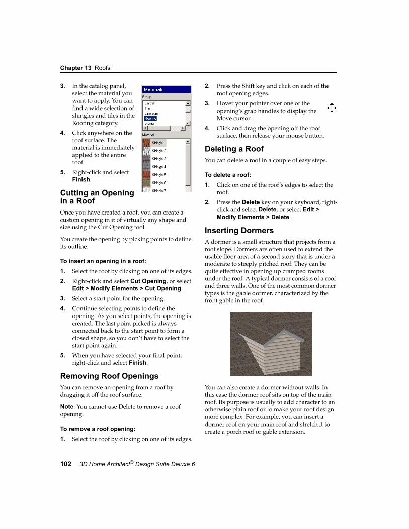
Chapter 13 Roofs
102 3D Home Architect® Design Suite Deluxe 6
3. In the catalog panel, select the material you want to apply. You can find a wide selection of shingles and tiles in the Roofing category.
4. Click anywhere on the roof surface. The material is immediately applied to the entire roof.
5. Right-click and select Finish.
Cutting an Opening in a RoofOnce you have created a roof, you can create a custom opening in it of virtually any shape and size using the Cut Opening tool.
You create the opening by picking points to define its outline.
To insert an opening in a roof:1. Select the roof by clicking on one of its edges.
2. Right-click and select Cut Opening, or select Edit > Modify Elements > Cut Opening.
3. Select a start point for the opening.
4. Continue selecting points to define the opening. As you select points, the opening is created. The last point picked is always connected back to the start point to form a closed shape, so you don’t have to select the start point again.
5. When you have selected your final point, right-click and select Finish.
Removing Roof OpeningsYou can remove an opening from a roof by dragging it off the roof surface.
Note: You cannot use Delete to remove a roof opening.
To remove a roof opening:1. Select the roof by clicking on one of its edges.
2. Press the Shift key and click on each of the roof opening edges.
3. Hover your pointer over one of the opening’s grab handles to display the Move cursor.
4. Click and drag the opening off the roof surface, then release your mouse button.
Deleting a RoofYou can delete a roof in a couple of easy steps.
To delete a roof:1. Click on one of the roof’s edges to select the
roof.
2. Press the Delete key on your keyboard, right-click and select Delete, or select Edit > Modify Elements > Delete.
Inserting DormersA dormer is a small structure that projects from a roof slope. Dormers are often used to extend the usable floor area of a second story that is under a moderate to steeply pitched roof. They can be quite effective in opening up cramped rooms under the roof. A typical dormer consists of a roof and three walls. One of the most common dormer types is the gable dormer, characterized by the front gable in the roof.
You can also create a dormer without walls. In this case the dormer roof sits on top of the main roof. Its purpose is usually to add character to an otherwise plain roof or to make your roof design more complex. For example, you can insert a dormer roof on your main roof and stretch it to create a porch roof or gable extension.

Moving a Dormer Roof
User’s Guide 103
13
Dormers are easy to insert - just point and click. You can control the dormer’s width, roof type, wall type, and wall height.
To create a dormer:1. In the building locations drop box, select the
location containing the roof you want to add the dormer to.
2. Select Insert > Roofs > Dormer Roof, or click the Roofs button on the Building toolbar and select Dormer Roof.
3. In the Dormers dialog, specify the desired width for the dormer in the Dormer Width edit box.
4. Click the Dormer Roof button, then select the desired roof type for the dormer. By default, the roof will have a gable front, regardless of the roof type. If you do not want it to have a gable front, uncheck the Gable Front check box.
5. If you want your dormer to have walls, check the Include Walls check box. Then, click the Dormer Wall button and select the desired wall type from the catalog. If you do not want your dormer to have walls, disable the Include Walls check box.
6. In the Support height above main roof edit box, type the height of the dormer’s front wall, not including the raked portion between the two roof slopes. You can use this
option even if you are not inserting walls to control the position of the bottom of the dormer roof. Note that dormer walls extend only to the roof surface.
7. Click OK. The dormer’s wall footprint is attached to your cursor.
8. Position the dormer where you want it, then click to insert it. In most cases you would place the front dormer wall directly on top of the exterior wall.
9. Right-click and select Finish.
Note: If you can’t seem to insert the dormer, it means that the dormer is too large for the surface you are inserting it on. You may want to try decreasing the wall height before inserting it.
Moving a Dormer RoofYou can use the Move Whole Element tool to move a dormer roof to another spot on your roof.
To move a dormer roof:1. Click on the edge of the dormer roof to select
it.

Chapter 13 Roofs
104 3D Home Architect® Design Suite Deluxe 6
2. Right-click and select Move Whole Element, or select Edit > Modify Element > Move Whole Element.
3. Click anywhere on the screen, then drag to move the dormer roof.
4. When the dormer roof is where you want it, release your mouse button.
Note: If the dormer has walls, you need to move the walls separately. To move the dormer walls, click on one wall, Shift+click to select the remaining walls, right-click and select Move, then click and drag the walls into place.
Stretching a Dormer RoofYou can stretch the front or sides a dormer roof by clicking and dragging the appropriate roof edge.
To stretch a dormer roof:1. Click on the roof edge you want to stretch. A
blue grab handle appears on the footprint line of the selected roof edge.
2. Position your pointer over the grab handle to display the Move cursor.
3. Click and drag to stretch the roof, then release your mouse button.
Note: If your dormer has walls, the dormer roof will not adjust if you stretch the dormer walls.
Deleting a DormerYou can delete a dormer roof in a couple of easy steps. If the dormer has walls, they need to be deleted separately.
To delete a dormer:1. Click on the edge of the dormer roof to select
it.
2. Press the Delete key on your keyboard, or right-click and select Delete, or select Edit > Modify Element > Delete.
3. If the dormer has walls, select one of the walls, then Shift+click to select the remaining walls. Use the Delete tool to delete the selected walls.
Inserting SkylightsYou can insert a skylight in your roof with point-and-click simplicity. The catalog contains a long list of skylights in a variety of sizes.
To insert a skylight:1. Select Insert > Skylights, or click the
Skylights button on the Building toolbar.
2. In the catalog, select the skylight you want to insert.
3. Position the skylight on the roof.
4. Click to insert the skylight.
5. Right-click and select Finish.
Moving a SkylightYou can move a skylight by clicking and dragging it.
To move a skylight:1. Click on the skylight to select it.
2. Hover your pointer over the center grab handle to display the Move cursor.
3. Click and drag the skylight to move it.
4. Release your mouse button.
Rotating a SkylightYou can rotate a skylight using the Rotate tool.
To rotate a skylight:1. Click on the skylight to select it.
2. Right-click and select Rotate, or select Edit > Modify Elements > Rotate.
3. Hover your pointer over the point you want to rotate around.
4. Click and drag to rotate the skylight, then release your mouse button.

Editing the Properties of a Skylight
User’s Guide 105
13
Editing the Properties of a SkylightSkylight properties include height and width, as well as dimensions for the frame and sash.
To edit the properties of a skylight:1. Click on the skylight to select it.
2. Right-click and select Properties, or select Edit > Modify Elements > Properties.
3. Edit the properties in the Properties window.
Height. The overall height of the skylight window opening.
Width. The overall width of the skylight window opening.
Frame Depth. The depth of the window frame.
Frame Width. The thickness of the window frame.
Sash Offset. The distance the sash sits back in the window frame. The sash is the frame that holds the glass.
Sash Depth. The thickness of the sash in plan view.
Sash Width. The width of the sash in elevation.
4. Once you’ve set your properties, click OK.
Deleting a SkylightYou can delete a skylight in a couple of easy steps.
To delete a skylight:1. Select the skylight.
2. Press the Delete key on your keyboard, or right-click and select Delete, or select Edit > Modify Elements > Delete.


Kitchen Builder Wizard page 109
Cabinets page 113
Appliances page 117
Furniture, Electronics & Accessories page 121
Designing the Interior
Part 4

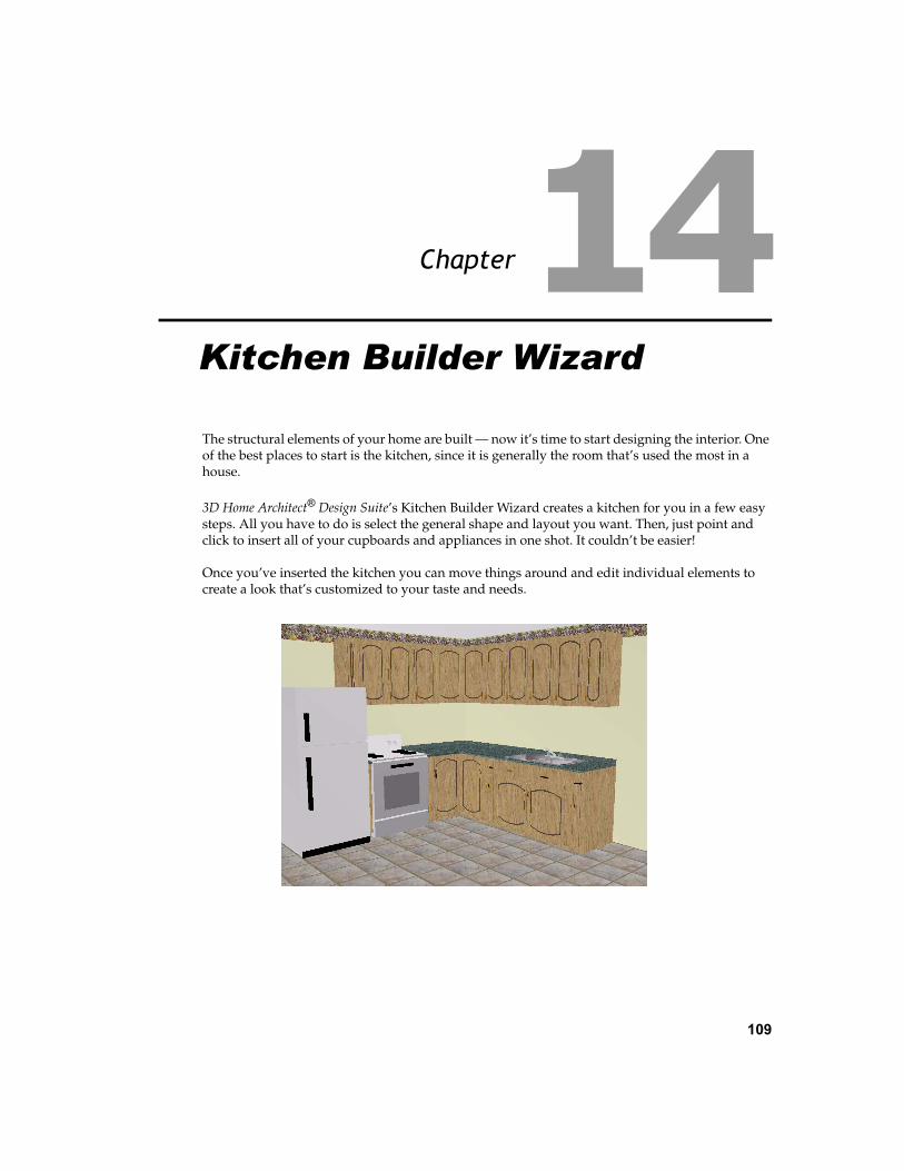
109
Chapter
The structural elements of your home are built — now it’s time to start designing the interior. One of the best places to start is the kitchen, since it is generally the room that’s used the most in a house.
3D Home Architect® Design Suite’s Kitchen Builder Wizard creates a kitchen for you in a few easy steps. All you have to do is select the general shape and layout you want. Then, just point and click to insert all of your cupboards and appliances in one shot. It couldn’t be easier!
Once you’ve inserted the kitchen you can move things around and edit individual elements to create a look that’s customized to your taste and needs.
Kitchen Builder Wizard

Chapter 14 Kitchen Builder Wizard
110 3D Home Architect® Design Suite Deluxe 6
Creating a Kitchen with the Kitchen Builder WizardUsing the Kitchen Builder Wizard you can quickly create a kitchen layout that includes upper and lower cabinets, a sink, refrigerator and stove. There are a number of layouts and styles to choose from.
To create a kitchen with the Kitchen Builder Wizard:1. Select Tools > Design Wizards > Kitchen
Builder.
2. Click Next.
3. Click on the general style of kitchen you want — L-Shape, Galley or U-Shape.
4. Click Next.
5. Select the layout that most closely resembles the layout you want. Remember that you can move and edit things later.
6. Click Next.
7. Select a general style for your kitchen. The selection you make mainly determines the materials and colors used for the cupboards and countertops.
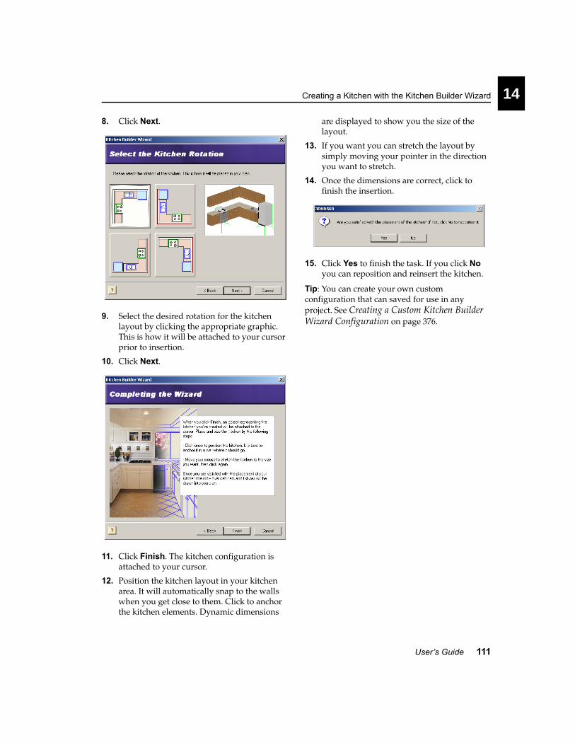
Creating a Kitchen with the Kitchen Builder Wizard
User’s Guide 111
14
8. Click Next.
9. Select the desired rotation for the kitchen layout by clicking the appropriate graphic. This is how it will be attached to your cursor prior to insertion.
10. Click Next.
11. Click Finish. The kitchen configuration is attached to your cursor.
12. Position the kitchen layout in your kitchen area. It will automatically snap to the walls when you get close to them. Click to anchor the kitchen elements. Dynamic dimensions
are displayed to show you the size of the layout.
13. If you want you can stretch the layout by simply moving your pointer in the direction you want to stretch.
14. Once the dimensions are correct, click to finish the insertion.
15. Click Yes to finish the task. If you click No you can reposition and reinsert the kitchen.
Tip: You can create your own custom configuration that can saved for use in any project. See Creating a Custom Kitchen Builder Wizard Configuration on page 376.


113
Chapter
Cabinets are essential for storage and can also contribute to the overall look and feel of a room. The catalog contains a huge selection of cabinet types, styles and sizes, all customizable to suit your taste and needs.
Cabinet types include base cabinets, corner cabinets, upper cabinets, islands, pantry cabinets and bathroom vanities.
You can insert cabinets in any room in your house with just a click of your mouse. Cabinets are designed to snap to walls and other cabinets, making insertion even easier.
Cabinets
Cabinets
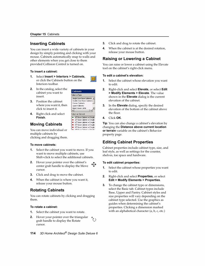
Chapter 15 Cabinets
114 3D Home Architect® Design Suite Deluxe 6
Inserting CabinetsYou can insert a wide variety of cabinets in your design by simply pointing and clicking with your mouse. Cabinets automatically snap to walls and other elements when you get close to them provided Collision Control is turned on.
To insert a cabinet:1. Select Insert > Interiors > Cabinets,
or click the Cabinets button on the Interiors toolbar.
2. In the catalog, select the cabinet you want to insert.
3. Position the cabinet where you want it, then click to insert it.
4. Right-click and select Finish.
Moving CabinetsYou can move individual or multiple cabinets by clicking and dragging them.
To move cabinets:1. Select the cabinet you want to move. If you
want to move multiple cabinets, use Shift+click to select the additional cabinets.
2. Hover your pointer over the cabinet’s center grab handle to display the Move cursor.
3. Click and drag to move the cabinet.
4. When the cabinet is where you want it, release your mouse button.
Rotating CabinetsYou can rotate cabinets by clicking and dragging them.
To rotate a cabinet:1. Select the cabinet you want to rotate.
2. Hover your pointer over the triangular grab handle to display the Rotate cursor.
3. Click and drag to rotate the cabinet.
4. When the cabinet is at the desired rotation, release your mouse button.
Raising or Lowering a Cabinet You can raise or lower a cabinet using the Elevate tool on the cabinet’s right-click menu.
To edit a cabinet’s elevation:1. Select the cabinet whose elevation you want
to edit.
2. Right-click and select Elevate, or select Edit > Modify Elements > Elevate. The value shown in the Elevate dialog is the current elevation of the cabinet.
3. In the Elevate dialog, specify the desired elevation of the bottom of the cabinet above the floor.
4. Click OK.
Tip: You can also change a cabinet’s elevation by changing the Distance above current location or terrain variable on the cabinet’s Behavior property page.
Editing Cabinet PropertiesCabinet properties include cabinet type, size, and leaf style, as well as settings for the counter, shelves, toe space and hardware.
To edit cabinet properties:1. Select the cabinet whose properties you want
to edit.
2. Right-click and select Properties, or select Edit > Modify Elements > Properties.
3. To change the cabinet type or dimensions, select the Basic tab. Cabinet types include Base, Upper and Pantry. Cabinet styles and size properties will vary depending on the cabinet type selected. Use the graphics as guides when determining the cabinet’s properties. Clicking a dimension marked with an alphabetical character (a, b, c, etc.)

Editing Cabinet Properties
User’s Guide 115
15
highlights the corresponding dimension in the cabinet graphic, and vice versa.
4. To change the cabinet’s leaf style, select the Leaf tab.
To select a leaf style for the door, select Door from the Apply to drop box, then make your selections. To select a leaf style for the draw-ers, if applicable, select Drawer from the Apply to drop box.
Leaf properties vary depending on the leaf style selected. Use the graphics as guides when setting these properties.
5. To edit the counter, shelving, toe space or hardware details, select the Details tab.
Show Counter. Displays a counter on the cabinet.
Thickness. The thickness of the counter material.
Show Backsplash. Displays a backsplash on the cabinet. The backsplash is a vertical sur-face designed to protect the wall behind a countertop.
Thickness. The thickness of the backsplash material.
Height. The distance from the countertop to the top of the backsplash.
Show Nosing. Displays nosing (moulded projection) on the front edge of the counter.
Thickness. The depth of the nosing.
Height. The height of the nosing.
Radius. The radius of the curve.
Show Shelves. Displays shelves inside the cabinet. The shelves would be visible if the cabinet door is glass.
Number of Shelves. The number of shelves you would like to display inside the cabinet.
Show Toe Space. Causes the bottom of the cabinet to recess so you can stand close to the cabinet without contacting it with their toes.
Toe Depth. The depth of the recess.

Chapter 15 Cabinets
116 3D Home Architect® Design Suite Deluxe 6
Toe Height. The height of the recess.
Show Handle. Displays handles on the cabi-net door and drawers, if present.
Handle Style. Choose from Box, Circle or Cylinder. A box style creates a rectangular handle. A circle style creates a round knob. The cylinder style creates a cylindrical han-dle.
Distance a. For pantry cabinets, this is the distance from the bottom of the upper cabi-net portion to the top of the door handle.
Distance b. The distance from the bottom of the cabinet to the top of the door handle.
6. When you’re finished editing properties, click OK.
Applying Different Finishes to CabinetsYou can use the Materials Paintbrush to quickly apply a different finish to a cabinet, such as a different type of wood, or another type of material altogether.
To apply a different finish to a cabinet:1. Display your model in 3D, and make sure the
cabinet is visible in the view.
2. Select Edit > Materials Paintbrush, or click the Materials Paintbrush button on any tabbed toolbar.
3. In the catalog panel, select the material you want to apply.
4. Click on the cabinet component you want to apply the material to. Materials are applied separately to the individual parts of the cabinet (frame, door, counter, handles, etc.).
5. When you are finished applying materials, right-click and select Finish.
Inserting a Sink into a CabinetYou can insert a kitchen or bathroom sink into a cabinet that you have inserted in your drawing by simply pointing and clicking. The sink automatically snaps itself into place at the center of the cabinet top.
To insert a sink into a cabinet:1. Select Insert > Interiors > Plumbing
Fixtures, or click the Plumbing Fixtures button on the Interiors toolbar.
2. In the catalog, select the Sinks category, then select the sink you want to insert.
3. Position the fixture inside the cabinet, then click to insert it.
4. Right-click and select Finish.
Deleting a CabinetYou can delete a cabinet in a couple of easy steps.
To delete a cabinet:1. Select the cabinet.
2. Press the Delete key on your keyboard, or right-click and select Delete, or select Edit > Modify Elements > Delete.

117
Chapter
Most home plans usually show the location of appliances in the kitchen and laundry room. Inserting appliances in your project can obviously enhance the design of a room, and can also help identify where electrical outlets are needed.
The 3D Home Architect® Design Suite catalog offers an excellent selection of kitchen and laundry appliances, including refrigerators, dishwashers, ovens, ranges, washers, dryers — even toasters. And of course, just like everything else, you can customize appliances to create the exact look you want.
Inserting appliances is easy — just point and click. Most major appliances are set to snap to walls and other elements when you get close to them.
Appliances
Appliances

Chapter 16 Appliances
118 3D Home Architect® Design Suite Deluxe 6
Inserting AppliancesYou can insert a wide variety of kitchen and laundry appliances in your design by simply pointing and clicking with your mouse. Appliances automatically snap to walls and other elements when you get close to them provided Collision Control is turned on.
To insert an appliance:1. Select Insert > Interiors >
Appliances, or click the Appliances button on the Interiors toolbar.
2. In the catalog, select the appliance you want to insert.
3. Position the appliance where you want it, then click to insert it.
4. Right-click and select Finish.
Note: If you are inserting a built-in oven, just position it where you want it in the wall and it will snap into place correctly with only the oven door and controls protruding from the wall.
Moving AppliancesYou can move individual appliances by clicking and dragging them.
To move an appliance:1. Select the appliance you want to move.
2. Hover your pointer over the appliance’s center grab handle to display the Move cursor.
3. Click and drag to move the appliance.
4. When the appliance is where you want it, release your mouse button.
Rotating AppliancesYou can rotate appliances by clicking and dragging them.
To rotate an appliance:1. Select the appliance you want to rotate.
2. Hover your pointer over the triangular grab handle to display the Rotate cursor.
3. Click and drag to rotate the appliance.
4. When the appliance is at the desired rotation, release your mouse button.
Raising or Lowering an Appliance You can raise or lower an appliance using the Elevate tool on the element’s right-click menu. For example, you might want to place a microwave on the kitchen counter.
To raise or lower an appliance:1. Select the appliance whose elevation you
want to edit.
2. Right-click and select Elevate, or select Edit > Modify Elements > Elevate. The value in the Elevate dialog is the current elevation of the appliance.
3. In the Elevate dialog, specify the desired elevation of the bottom of the appliance above the floor.
4. Click OK.
Tip: You can also change an appliance’s elevation by changing the Distance above current location or terrain variable on the appliance’s Behavior property page.
Editing Appliance Size PropertiesYou can edit the height, width and depth of most appliances. Some appliances have additional properties that define their size and style.
To edit appliance properties:1. Select the appliance whose properties you
want to edit.

Applying a Different Color or Finish to Appliances
User’s Guide 119
16
2. Right-click and select Properties, or select Edit > Modify Elements > Properties.
3. To change the size or style of the appliance, select the Basic tab. Appliance styles and size properties will vary depending on the appliance. Use the graphics as guides when determining the appliance’s properties. Clicking a dimension marked with an alphabetical character (a, b, c, etc.) highlights the corresponding dimension in the appliance graphic, and vice versa.
4. Once you’ve specified the properties, click OK.
Applying a Different Color or Finish to AppliancesYou can use the Materials Paintbrush to quickly change the color or finish of an appliance.
To apply a color or finish to an appliance:1. Display your model in 3D, and make sure the
appliance is visible in the view.
2. Select Edit > Materials Paintbrush, or click the Materials Paintbrush button on any tabbed toolbar.
3. In the catalog panel, select the color or finish you want to apply. You can find an assortment of colors in the Paint category. For the stainless steel look you may want to try the Silver material in the Finishes category.
4. Click on the appliance component you want to apply the material to. Materials are applied separately to the individual parts of the appliance. For example, you can select a different color just for a knob or handle.
5. When you are finished applying materials, right-click and select Finish.
Deleting an ApplianceYou can delete an appliance in a couple of easy steps.
To delete an appliance:1. Select the appliance.
2. Press the Delete key on your keyboard, right-click and select Delete, or select Edit > Modify Elements > Delete.


121
Chapter
Once you’ve got your cabinets and appliances in place, you can jump right into the fun stuff — furnishing and decorating your home. The catalog contains so many different types of furniture, electronics and decorative accessories, the possibilities are endless. And with easy, point-and-click insertion, you can play around with different design ideas and quickly decorate every room of your home, just the way you want it.
AccessoriesElectronicsFurniture
Furniture, Electronics & Accessories

Chapter 17 Furniture, Electronics & Accessories
122 3D Home Architect® Design Suite Deluxe 6
Inserting FurnitureThe catalog contains a variety of furnishings for every room in your home — everything from beds to CD stands. Furnishings automatically snap to walls and other elements when you get close to them provided Collision Control is turned on.
To insert furniture:1. Select Insert > Interiors > Furniture,
or click the Furniture button on the Interiors toolbar.
2. In the catalog, select the element you want to insert.
3. Position the element where you want it, then click to insert it.
4. Right-click and select Finish.
Inserting ElectronicsElectronics include televisions, computers, clocks and telephones.
To insert electronics:1. Select Insert > Interiors >
Electronics, or click the Electronics button on the Interiors toolbar.
2. In the catalog, select the element you want to insert.
3. Position the element where you want it, then click to insert it.
4. Right-click and select Finish.
Inserting AccessoriesAccessories are those small, personal touches that really pull a room together. They are things like curtains, blinds, towel racks, shower curtains,
medicine cabinets, plates, bowls, cups, mirrors and pictures.
To insert accessories:1. Select Insert > Interiors >
Accessories, or click the Accessories button on the Interiors toolbar.
2. In the catalog, select the element you want to insert.
3. Position the element where you want it, then click to insert it.
4. Right-click and select Finish.
Moving Furnishing ElementsYou can move furniture, electronics and accessories by clicking and dragging them.
To move an element:1. Select the element you want to move.
2. Hover your pointer over the cabinet’s center grab handle to display the Move cursor.
3. Click and drag to move the element.
4. When the element is where you want it, release your mouse button.
Rotating Furnishing ElementsYou can rotate furniture, electronics and accessories by clicking and dragging them.
To rotate an element:1. Select the element you want to rotate.
2. Hover your pointer over the triangular grab handle to display the Rotate cursor.
3. Click and drag to rotate the element.
4. When the element is at the desired rotation, release your mouse button.

Raising or Lowering a Furnishing Element
User’s Guide 123
17
Raising or Lowering a Furnishing Element You can raise or lower furniture, electronics and accessories using the Elevate tool on the element’s right-click menu. For example, you might want to adjust the height of a picture on the wall.
To edit the elevation of a furnishing element:1. Select the element whose elevation you want
to edit.
2. Right-click and select Elevate, or select Edit > Modify Elements > Elevate. The value shown in the Elevate dialog is the current elevation of the element.
3. In the Elevate dialog, specify the desired elevation of the bottom of the element above the floor.
4. Click OK.
Tip: You can also change a furnishing element’s elevation by changing the Distance above current location or terrain variable on the element’s Behavior property page.
Editing the Size of Furnishing ElementsYou can edit the height, width and depth of most furnishing elements. Some elements have additional properties that define their size and style.
To edit the size of furnishing elements:1. Select the element whose properties you
want to edit.
2. Right-click and select Properties, or select Edit > Modify Elements > Properties.
3. To change the dimensions of the element, select the Basic tab. Size properties will vary depending on the element.
4. Once you’ve specified the properties, click OK.
Applying Different Colors, Fabrics and Finishes to Furnishing ElementsYou can use the Materials Paintbrush to quickly apply a color, fabric or finish to any furnishing element.
To apply a material to a furnishing element:1. Display your model in 3D, and make sure the
furnishing element is visible in the view.
2. Select Edit > Materials Paintbrush, or click the Materials Paintbrush button on any tabbed toolbar.

Chapter 17 Furniture, Electronics & Accessories
124 3D Home Architect® Design Suite Deluxe 6
3. In the catalog panel, select the color or material you want to apply. You can find an assortment of colors in the Paint category.
4. Click on the component you want to apply the material to. Materials are applied separately to the individual parts of the element. For example, you can apply a specific fabric to the bedspread on a bed.
5. When you are finished applying materials, right-click and select Finish.
Deleting Furnishing ElementsYou can delete furniture, electronics or accessories in a couple of easy steps.
To delete a furnishing element:1. Select the element.
2. Press the Delete key on your keyboard, right-click and select Delete, or select Edit > Modify Elements > Delete.

Interior Lighting page 127
Electrical page 133
Plumbing page 139
Heating & Ventilation page 143
UtilitiesPart 5


127
Chapter
Interior lighting can drastically change the look and atmosphere of a room. They also play an important part when you create interior 3DTrueView™ renderings. 3D Home Architect® Design Suite provides an excellent selection of ceiling lights, wall lights, track lights, recessed lights and lamps for you to insert. You can even turn them on and off!
Lights are inserted at a logical height in your plan depending on their type, making accurate placement easy. Also, ceiling lights snap to ceilings, and wall lights snap to walls. Just point and click!
Lighting
Interior Lighting

Chapter 18 Interior Lighting
128 3D Home Architect® Design Suite Deluxe 6
Inserting Interior Light Fixtures3D Home Architect® Design Suite offers a good selection of lighting fixtures for the interior of your home. Interior light fixtures include ceiling lights, wall lights, track lighting, recessed lights, and lamps.
Each lighting fixture has a light source in its property definition, such as an incandescent light bulb. Lights are particularly important if you plan to create a 3DTrueView of your model, since the program uses light to calculate and create the rendered view.
With the exception of lamps, light fixtures are set to snap to either ceilings or walls depending on what kind of fixture they are.
Note: If you want to insert exterior light fixtures, use the Landscape Lighting tool.
To insert a light fixture:
1. Select Insert > Interiors > Lighting, or click the Lighting button on the Interiors toolbar.
2. In the catalog, select the light fixture you want to insert.
3. Position the light where you want it, then click to insert it. If you want the light to snap to a ceiling or wall and it isn’t, or you want to stop the light from snapping, see Changing the Way a Light Snaps on Insertion below.
4. Right-click and select Finish.
Changing the Way a Light Snaps on InsertionBy default, ceiling lights are set to snap to ceilings, and wall lights are set to snap to walls. Lamps have no snap setting so that you can place them anywhere in a room. You can change a light fixture’s snap setting on the fixture’s Behavior property page.
To change the way a light snaps on insertion:1. In the catalog, select the light fixture whose
snap setting you want to change.
2. Right-click and select Catalog Manager. You can also access the Catalog Manager by selecting File > Catalogs > Catalog Manager.
3. In the Catalog Manager dialog, make sure the correct fixture is selected, then select Catalog > Element Properties.
4. In the Lights dialog, select the Behavior tab.
5. From the Snap Light to drop box, select either Ceiling, Wall or None.
6. Click OK in the Lights dialog.
7. Click OK.
Raising or Lowering a Light FixtureYou can raise or lower a light fixture using the Elevate tool on the fixture’s right-click menu.
To raise or lower a light fixture:1. Select the fixture whose elevation you want
to edit.
2. Right-click and select Elevate, or select Edit > Modify Elements > Elevate. The value shown in the Elevate dialog is the current elevation of the light fixture.
3. In the Elevate dialog, specify the desired elevation of the fixture above the floor.
4. Click OK.
Tip: You can also change a light fixture’s elevation by changing the Distance above current location or terrain variable on the fixture’s Behavior property page.
Moving Light FixturesYou can move light fixtures by clicking and dragging them.
To move a light fixture:1. Select the light fixture you want to move.

Rotating Light Fixtures
User’s Guide 129
18
2. Hover your pointer over the fixture’s center grab handle to display the Move cursor.
3. Click and drag to move the light fixture.
4. When the light fixture is where you want it, release your mouse button.
Rotating Light FixturesYou can rotate light fixtures by clicking and dragging them.
To rotate a light fixture:1. Select the light fixture you want to rotate.
2. Hover your pointer over the triangular grab handle to display the Rotate cursor.
3. Click and drag to rotate the light fixture.
4. When the light fixture is at the desired rotation, release your mouse button.
Editing the Size of Light FixturesYou can edit the dimensions of a light fixture on its Basic property page.
To edit the size of a light fixture:1. Select the light fixture whose properties you
want to edit.
2. Right-click and select Properties, or select Edit > Modify Elements > Properties.
3. Select the Basic tab. Size properties will vary depending on the type of fixture. Use the diagram as a guide when determining the fixture’s properties. Clicking a dimension marked with an alphabetical character (a, b, c, etc.) highlights the corresponding dimension in the light fixture diagram, and vice versa.
4. Click OK.
Editing a Light Fixture’s Light SourceA light source is usually a type of light bulb. You can edit a light fixture’s light source to achieve a different lighting effect.
To edit a light fixture’s light source:1. Select the light fixture whose properties you
want to edit.
2. Right-click and select Properties, or select Edit > Modify Elements > Properties.
3. Select the Lights tab.
4. To replace the currently selected light source with another type, click Edit, then select a light source from the Light Sources dialog. To add a light source to the fixture, click Add,

Chapter 18 Interior Lighting
130 3D Home Architect® Design Suite Deluxe 6
then select a light source from the Light Sources dialog.
5. To delete a light source from the light fixture, click Delete.
6. To edit the position of the light source in relation to the light fixture, specify the X, Y and Z coordinates in the Light Position area. Coordinates are measured from the bottom center of the fixture. The small red box in the preview window indicates the current position of the light source. Changing the X value moves the light source left or right. Selecting Middle positions the light in the center of the fixture, and selecting Minimum or Maximum positions it on the left or right side. If you select Custom you can enter a specific value in the adjacent edit box which is relative to the center position. For example, entering -3 moves the light source 3” left from the center. Changing the Y value moves the light source forward or backward. Selecting Minimum brings the light source all the way forward, and selecting Maximum moves it to the back of the fixture. Changing the Z value moves the light source up or down. Selecting Minimum positions the light source at the bottom of the fixture, while selecting Maximum positions it at the top of the fixture.
7. Once you’ve specified the properties, click OK.
Turning a Light On or OffBy default, lights are on when you insert them. You can virtually turn a light off by disabling its light source.
To turn a light on or off:1. Select the light fixture you want to turn on or
off.
2. Right-click and select Properties, or select Edit > Modify Elements > Properties.
3. Select the Lights tab.
4. To turn the light on or off, click the eye icon next to the light source name.
5. Click OK.
Changing the Look of a Light FixtureYou can use the Materials Paintbrush to apply different colors or materials to different parts of a light fixture. For example, you may want to change the color of a lamp shade.
To change the look of a light fixture:1. Display your model in 3D, and make sure the
light fixture is visible in the view.
2. Select Edit > Materials Paintbrush, or click the Materials Paintbrush button on any tabbed toolbar.
eye icon

Deleting Light Fixtures
User’s Guide 131
18
3. In the catalog panel, select the material you want to apply.
4. Click on the component you want to apply the material to. Materials are applied separately to the individual parts of the light fixture.
5. When you are finished applying materials, right-click and select Finish.
Deleting Light FixturesYou can delete a light fixture in a couple of easy steps.
To delete a light fixture:1. Select the fixture.
2. Press the Delete key on your keyboard, right-click and select Delete, or select Edit > Modify Elements > Delete.


133
Chapter
3D Home Architect® Design Suite makes it easy to insert electrical outlets, switches, thermostats and smoke detectors in your plan — just point and click. Electrical elements automatically snap to walls and are inserted at a logical height depending on their type, making it easy to place them accurately.
Once you’ve inserted electrical elements you may want to draw wiring in your 2D plan. All it takes is a few clicks of the mouse.
Electrical

Chapter 19 Electrical
134 3D Home Architect® Design Suite Deluxe 6
Inserting Outlets and SwitchesYou can insert electrical outlets and light switches in your plan with a single mouse click. The backs of these elements automatically snap to walls and are inserted at a logical height on the wall, making accurate placement effortless. You can move, raise and lower these elements after you have inserted them.
To insert outlets and switches:1. Select Insert > Interiors > Electrical >
Electrical Elements, or click the Electrical button on the Interiors toolbar and select Electrical Elements.
2. In the catalog, select the element you want to insert.
3. Position the element where you want it, then click to insert it.
4. Right-click and select Finish.
Inserting Thermostats and Smoke DetectorsTo insert a thermostat or smoke detector, all you need to do is point and click. Thermostats are set to automatically snap to walls and are inserted at a default height of 5’. Smoke detectors insert a default height of 8’. You can move, raise or lower thermostats and smoke detectors after you have inserted them.
To insert thermostats and smoke detectors:1. Select Insert > Interiors > Electrical >
Electrical Elements, or click the Electrical
button on the Interiors toolbar and select Electrical Elements.
2. In the catalog, select the Sensors category, then select the element you want to insert.
3. Position the element where you want it, then click to insert it.
4. Right-click and select Finish.
Raising or Lowering an Electrical ElementYou can raise or lower an outlet, switch, thermostat or smoke detector using the Elevate tool.
To raise or lower an electrical element:1. Select the element whose elevation you want
to edit.
2. Right-click and select Elevate, or select Edit > Modify Elements > Elevate. The value shown in the Elevate dialog is the current elevation of the element.
3. In the Elevate dialog, specify the desired elevation of the bottom of the element above the floor.
4. Click OK.
Tip: You can also change an element’s elevation by changing the Distance above current location or terrain variable on the element’s Behavior property page.

Moving an Electrical Element
User’s Guide 135
19
Moving an Electrical ElementYou can move outlets, switches, thermostats and smoke detectors in plan view by simply clicking and dragging them.
To move an element:1. Select the element you want to move.
2. Hover your pointer over the element’s center grab handle to display the Move cursor.
3. Click and drag to move the element.
4. When the element is where you want it, release your mouse button.
Editing the Size of an Electrical ElementYou can edit the height, width and depth of most electrical elements. Some elements have additional dimensions for individual components in the element.
To edit the size of an electrical element:1. Select the element whose size you want to
edit.
2. Right-click and select Properties, or select Edit > Modify Elements > Properties.
3. Edit the properties as desired.
4. Click OK.
Applying a Different Color or Material to an Electrical ElementYou can use the Materials Paintbrush to apply a different color or material to an electrical element.
To apply a color or material to an electrical element:1. Display your model in 3D, and make sure the
electrical element is visible in the view.
2. Select Edit > Materials Paintbrush, or click the Materials Paintbrush button on any tabbed toolbar.
3. In the catalog panel, select the color or material you want to apply. You can find an assortment of colors in the Paint category.
4. Click on the electrical element. The color or material is applied immediately.
5. Right-click and select Finish.
Deleting Electrical ElementsYou can delete an outlet, switch, thermostat or smoke detector in a couple of easy steps.
To delete an electrical element:1. Select the element.
2. Press the Delete key on your keyboard, right-click and select Delete, or select Edit > Modify Elements > Delete.

Chapter 19 Electrical
136 3D Home Architect® Design Suite Deluxe 6
Inserting WiringOnce you’ve inserted electrical elements, you can use the Wiring tool to indicate the location of electrical wiring in your 2D plan. By default, wiring lines have arched segments and use a dashed linestyle. You can stretch and reshape individual segments after you’ve inserted the line. You can also edit the linestyle. Wiring is only visible in 2D plan view.
To add electrical wiring:1. Select Insert > Interiors > Electrical >
Wiring, or click the Electrical button on the Interiors toolbar and select Wiring.
2. Select a start point for the wiring line.
3. Select the next point for the wiring line. An arched line segment is created between the two points.
4. Continue selecting points to add more segments.
5. Right-click and select Finish.
Note: You can change the line style of individual wires if you want. See Changing the Line Style of Wiring on page 136. You can also mark your wiring lines with text. See Adding Text to Your Drawing on page 274.
Stretching and Reshaping Wiring SegmentsYou can stretch individual segments in a wiring line by clicking and dragging their grab handles. Stretching wiring segments can change their length or shape.
To stretch a wiring segment:1. Select the segment you want to stretch. Grab
handles are displayed along the segment.
2. Hover your pointer over the grab handle you want to grab and stretch.
3. Click and drag to stretch the line, then release your mouse button.
Changing the Line Style of WiringBy default, electrical wiring is displayed using the Electrical Power Distribution line style, which is a brown, dashed line. You can select a different line style for selected wiring segments if you want. For example, you may want to select the Telephone line style for your telephone lines.
To change the line style of wiring:1. Select one of the line segments you want to
change. Use Shift+click to select the remaining segments in the line.
2. Right-click and select Properties, or select Edit > Modify Elements > Properties.
3. In the Line Styles dialog, select the line style you want to use.
1 2 3 4

Deleting Wiring
User’s Guide 137
19
If you want to edit a line style, click one of the swatches to access the Edit Line Styles dialog. To add a new line style to the list, select Linestyle > Add Linestyle. For more information, see the Line Styles chapter page 355.
4. Click OK. The line style is updated in your drawing.
Deleting WiringYou can delete individual wiring segments or an entire wire in a couple of easy steps.
To delete wiring:1. Select the wiring segment you want to delete.
To select an entire wire, drag a selection window around it.
2. Press the Delete key on your keyboard, right-click and select Delete, or select Edit > Modify Elements > Delete.


139
Chapter
3D Home Architect® Design Suite offers a complete selection of sinks, faucets, tubs, showers, toilets and bidets to help you properly equip your home. Plumbing fixtures are inserted with a single mouse click and will automatically snap to walls if Collision Control is turned on. You can control which edge of a fixture snaps to the wall, as well as edit the fixture’s size, style and elevation.
Plumbing
Plumbing

Chapter 20 Plumbing
140 3D Home Architect® Design Suite Deluxe 6
Inserting Plumbing FixturesPlacing plumbing fixtures in your plan is easy — just select what you want to insert, then point and click. With Collision Control turned on, fixtures will automatically snap to walls when you get close to them. Also, fixtures will insert at a logical height. For example, a toilet will insert on the floor, while a sink may insert 3’ off the floor. You can edit a fixture’s size and elevation, as well as move and rotate it.
Note: The first four sinks in the Sinks category (kitchen and bathroom sinks) can only be inserted into a cabinet. Also, the cabinet must be large enough to house the sink.
To insert plumbing fixtures:1. Select Insert > Interiors > Plumbing
Fixtures, or click the Plumbing Fixtures button on the Interiors toolbar.
2. In the catalog, select the fixture you want to insert.
3. Position the fixture where you want it, then click to insert it.
4. Right-click and select Finish.
Raising or Lowering a Plumbing FixtureYou can raise or lower a plumbing fixture using the Elevate tool on the fixture’s right-click menu.
To edit a plumbing fixture’s elevation:1. Select the fixture whose elevation you want
to edit.
2. Right-click and select Elevate, or select Edit > Modify Elements > Elevate. The value shown in the Elevate dialog is the current elevation of the element.
3. In the Elevate dialog, specify the desired elevation of the bottom of the fixture above the floor.
4. Click OK.
Tip: You can also change a plumbing fixture’s elevation by changing the Distance above current location or terrain variable on the fixture’s Behavior property page.
Moving Plumbing FixturesYou can move plumbing fixtures by clicking and dragging them.
To move a plumbing fixture:1. Select the plumbing fixture you want to
move.
2. Hover your pointer over the fixture’s center grab handle to display the Move cursor.
3. Click and drag to move the fixture.
4. When the fixture is where you want it, release your mouse button.
Rotating Plumbing FixturesYou can rotate plumbing fixtures by clicking and dragging them.
To rotate a plumbing fixture:1. Select the fixture you want to rotate.
2. Hover your pointer over the triangular grab handle to display the Rotate cursor.
3. Click and drag to rotate the fixture.
4. When the fixture is at the desired rotation, release your mouse button.
Editing the Size of a Plumbing FixtureYou can edit the height, width and depth of a plumbing fixture.
To edit the properties of a plumbing fixture:1. Select the plumbing fixture whose properties
you want to edit.

Applying a Different Color or Finish to Plumbing Fixtures
User’s Guide 141
20
2. Right-click and select Properties, or select Edit > Modify Elements > Properties.
3. Edit the properties as desired.
4. Click OK.
Applying a Different Color or Finish to Plumbing FixturesYou can use the Materials Paintbrush to apply different colors or finishes to different parts of a plumbing fixture.
To apply a color or finish to a plumbing fixture:1. Display your model in 3D, and make sure the
fixture is visible in the view.
2. Select Edit > Materials Paintbrush, or click the Materials Paintbrush button on any tabbed toolbar.
3. In the catalog panel, select the color or finish you want to apply. You can find an assortment of colors in the Paint category.
4. Click on the component you want to apply the material to. Materials are applied separately to the individual parts of the plumbing fixture. For example, you can select a different color just for a tap or handle.
5. When you are finished applying materials, right-click and select Finish.
Deleting Plumbing FixturesYou can delete a plumbing fixture in a couple of easy steps.
To delete a plumbing fixture:1. Select the fixture.
2. Press the Delete key on your keyboard, right-click and select Delete, or select Edit > Modify Elements > Delete.


143
Chapter
The correct placement of heating and ventilation elements is an important part of the home design process. Laying out HVAC elements in 3D Home Architect® Design Suite is quick and easy - just point and click.
The catalog contains just about anything you’d need — furnaces, fireplaces, wood stoves, chimneys, water heaters, floor registers and cold air returns. Of course, just like anything else, you can move, rotate and edit these elements if you change your mind.
HVAC
Heating & Ventilation

Chapter 21 Heating & Ventilation
144 3D Home Architect® Design Suite Deluxe 6
Inserting Heating ElementsYou can insert heating elements with a click of your mouse. Heating elements include fireplaces, wood stoves, furnaces and water heaters. By default, heating elements are inserted on the floor and will snap to walls if Collision Control is turned on.
To insert a heating element:1. Select Insert > Interiors > HVAC
Elements, or click the HVAC Elements button on the Interiors toolbar.
2. In the catalog, select the Heating category, then select the element you want to insert.
3. Position the element where you want it, then click to insert it.
4. Right-click and select Finish.
Inserting Floor Registers and Cold Air ReturnsRegisters and air returns come in a variety of sizes, but you can create a different size if you need to. Wall air returns will insert directly onto walls. You can change the height of them later if you want.
To insert a ventilation element:1. Select Insert > Interiors > HVAC
Elements, or click the HVAC Elements button on the Interiors toolbar.
2. In the catalog, select the Ventilation category, then select the element you want to insert.
3. Position the element where you want it, then click to insert it.
4. Right-click and select Finish.
Inserting a ChimneyChimneys by default are 12’ tall, but you can change this before or after you insert the chimney to create the correct height needed for your house. By default, the chimney in the catalog has a brick base and concrete cap. You can edit the appearance of the chimney to match the exterior of your home if you are inserting the chimney on the outside.
To insert a chimney:1. Select Insert > Interiors > HVAC
Elements, or click the HVAC Elements button on the Interiors toolbar.
2. In the catalog, select the Ventilation category, then select the Chimney element.
3. Position the chimney where you want it, then click to insert it.
4. Right-click and select Finish.
To edit the height of the chimney:1. Select the chimney.
2. Right-click and select Properties, or select Edit > Modify Elements > Properties.
3. On the Basic property page, change the value in the Base Height edit box.
4. Click OK.
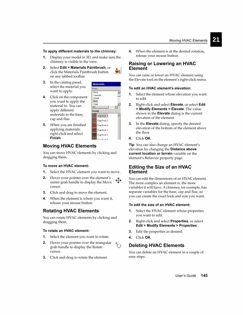
Moving HVAC Elements
User’s Guide 145
21
To apply different materials to the chimney:1. Display your model in 3D, and make sure the
chimney is visible in the view.
2. Select Edit > Materials Paintbrush, or click the Materials Paintbrush button on any tabbed toolbar.
3. In the catalog panel, select the material you want to apply.
4. Click on the component you want to apply the material to. You can apply different materials to the base, cap and flue.
5. When you are finished applying materials, right-click and select Finish.
Moving HVAC ElementsYou can move HVAC elements by clicking and dragging them.
To move an HVAC element:1. Select the HVAC element you want to move.
2. Hover your pointer over the element’s center grab handle to display the Move cursor.
3. Click and drag to move the element.
4. When the element is where you want it, release your mouse button.
Rotating HVAC ElementsYou can rotate HVAC elements by clicking and dragging them.
To rotate an HVAC element:1. Select the element you want to rotate.
2. Hover your pointer over the triangular grab handle to display the Rotate cursor.
3. Click and drag to rotate the element.
4. When the element is at the desired rotation, release your mouse button.
Raising or Lowering an HVAC ElementYou can raise or lower an HVAC element using the Elevate tool on the element’s right-click menu.
To edit an HVAC element’s elevation:1. Select the element whose elevation you want
to edit.
2. Right-click and select Elevate, or select Edit > Modify Elements > Elevate. The value shown in the Elevate dialog is the current elevation of the element.
3. In the Elevate dialog, specify the desired elevation of the bottom of the element above the floor.
4. Click OK.
Tip: You can also change an HVAC element’s elevation by changing the Distance above current location or terrain variable on the element’s Behavior property page.
Editing the Size of an HVAC ElementYou can edit the dimensions of an HVAC element. The more complex an element is, the more variables it will have. A chimney, for example, has separate variables for the base, cap and flue, so you can create the exact look and size you want.
To edit the size of an HVAC element:1. Select the HVAC element whose properties
you want to edit.
2. Right-click and select Properties, or select Edit > Modify Elements > Properties.
3. Edit the properties as desired.
4. Click OK.
Deleting HVAC ElementsYou can delete an HVAC element in a couple of easy steps.

Chapter 21 Heating & Ventilation
146 3D Home Architect® Design Suite Deluxe 6
To delete an HVAC element:1. Select the element.
2. Press the Delete key on your keyboard, right-click and select Delete, or select Edit > Modify Elements > Delete.

147
Terrain Modeling page 149
Property Lines page 157
Terrain Modeling
Part 6


149
Chapter
3D Home Architect® Design Suite goes well beyond home design by letting you recreate the topography of the lot your home will be built on.
By default, a basic 150’ x 150’ grass terrain is displayed in the drawing area. In 2D view, only the boundary of the terrain is shown (you may need to zoom out to see it). Contour lines may also be visible depending on the terrain’s defined properties. In 3D view, the terrain is displayed as a solid, 3D object. It can be viewed in wireframe, hidden line or rendered form. You add hills, berms, plateaus and slopes to your terrain to create an incredibly realistic-looking building site.
Terrain Modeling

Chapter 22 Terrain Modeling
150 3D Home Architect® Design Suite Deluxe 6
Defining the Basic TerrainYou can control the base level, size (length and width), mesh spacing, and contour interval of the terrain. You can also select a texture to use when displaying the terrain in rendered view (the default is grass).
You can specify whether or not you want the terrain to cut around your building, and select the location that you want the terrain to cut around.
To define the terrain:
1. Select Settings > Terrain Settings, or click the Terrain Settings button on the Settings toolbar.
2. In the Terrain Settings dialog, set your terrain options:
3. To force the terrain to cut around a building, enable the Auto-cut terrain around building check box, then select the building location that you want the terrain to cut around from the Select Building Location to cut around drop box.
4. To change the level at which the base of the terrain sits, type the desired value in the Terrain Base Level edit box. This value is measured from 0.
5. To change the overall size of the terrain, enter the desired values in the Length and Width edit boxes.
6. To change the spacing between mesh lines (when viewing the terrain in Wireframe, Hidden Line or Patterned view), enter the
desired value in the Grid Mesh Spacing edit box.
7. To change the texture used for the terrain, click the Select button in the Material area, then make your selection in the Materials dialog.
8. To display contours on your terrain, enable the Show contours check box. In the Start edit box, enter the elevation of the first contour. In the Interval check box, enter the desired spacing between contours.
9. Click OK.
Creating Hills and ValleysYou can add hills to your terrain with a single mouse click. You can control the height of a hill as well as its peak shape. Generally, the diameter of the hill base is the same as the hill height. You can insert multiple hills together to create one larger hill. Also, if you insert hills next to other terrain elements, like plateaus or slopes, the elements will automatically blend together.

Creating Berms and Trenches
User’s Guide 151
22
To create a hill or valley:1. Select Insert > Terrain > Hills /
Valleys, or click the Hills/Valleys button on the Terrain toolbar.
2. In the Hills / Valleys dialog, specify the height of the hill in the Height edit box. Entering a negative value will create a valley.
3. Using the Zenith slider control, select a peak shape for the hill.
4. Click OK.
5. Click to insert the hill. You can insert multiple hills if you like.
6. Right-click and select Finish.
To move a hill/valley:1. Click in the center of the hill to select it.
2. Click and drag the center grab handle to move the hill, then release your mouse button.
To edit the height or peak shape of a hill:1. Click in the center of the hill to select it.
2. Right-click and select Properties, or select Edit > Modify Elements > Properties.
3. Edit the properties in the Hills/Valleys dialog.
4. Click OK.
To remove a hill/valley:1. Click in the center of the hill to select it.
2. Press the Delete key on your keyboard, or right-click and select Delete, or select Edit > Modify Elements > Delete.
Creating Berms and TrenchesA berm is a mound or bank of soil without formal sides. You often see large berms on the sides of highways, which are used for noise control. On a reduced scale, a natural berm can provide some interesting benefits in a backyard landscape. These include:
Climate control. Berms act as windbreaks, channeling air flow. Berms can create a warmer microclimate or direct cooling breezes.
Privacy. A berm can be a "friendly fence" in the back yard or between your house and a sidewalk.
Vertical interest. You can add variety and texture to your gardens with berms, change the view from your outdoor sitting areas, or even hide eyesores with them.
Noise control. A berm can cut down on traffic noise if you live on a busy street or near a schoolyard.
Berms may be shored with stone, bricks, or timbers, and planted with groundcovers, perennials, annuals, trees, etc.
You can control the height of a berm as well as its peak shape.

Chapter 22 Terrain Modeling
152 3D Home Architect® Design Suite Deluxe 6
To create a berm/trench:1. Select Insert > Terrain > Berms/
Trenches, or click the Berms/Trenches button on the Terrain toolbar.
2. In the Berms/Trenches dialog, specify the height of the berm in the Height edit box. Entering a negative value creates a trench.
3. Using the Zenith slider control, select a peak shape for the berm.
4. Click OK.
5. Select two points to define the length of the top of the berm. The berm will be created downward and outward from this line.
6. Right-click and select Finish.
To stretch a berm/trench:1. Click in the center of the berm to select it.
2. Grab handles are displayed at either end of the berm’s central line.
3. Click and drag an end grab handle to stretch the berm, then release your mouse button. You can move the end point to any position on the screen.
To move a berm/trench:1. Click in the center of the berm to select it. A
blue grab handle is displayed in the middle of the berm’s central line.
2. Click and drag the central blue grab handle to move the berm, then release your mouse button.
To rotate a berm/trench:1. Click in the center of the berm to select it.
Grab handles are displayed along the berm’s central line.
2. Click and drag a grab handle to rotate the berm around the selected point.
3. Release your mouse button.
To edit the height or peak shape of a berm:1. Click in the center of the berm to select it.
2. Right-click and select Properties, or select Edit > Modify Elements > Properties.
3. Edit the properties in the Berms/Trenches dialog.
4. Click OK.
To delete a berm/trench:1. Click in the center of the berm to select it.
2. Press the Delete key on your keyboard, or right-click and select Delete, or select Edit > Modify Elements > Delete.
Creating PlateausA plateau is a relatively large, flat area of land situated above the adjacent land. Adding a plateau to your terrain involves clicking a few points to define the shape of the plateau. You can control the height of the plateau as well as its peak shape. Note that if you insert a plateau in close proximity to other terrain elements, such as hills, the elements automatically blend together.
21
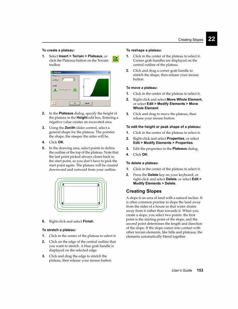
Creating Slopes
User’s Guide 153
22
To create a plateau:1. Select Insert > Terrain > Plateaus, or
click the Plateaus button on the Terrain toolbar.
2. In the Plateaus dialog, specify the height of the plateau in the Height edit box. Entering a negative value creates an excavated area.
3. Using the Zenith slider control, select a general shape for the plateau. The pointier the shape, the steeper the sides will be.
4. Click OK.
5. In the drawing area, select points to define the outline of the top of the plateau. Note that the last point picked always closes back to the start point, so you don’t have to pick the start point again. The plateau will be created downward and outward from your outline.
6. Right-click and select Finish.
To stretch a plateau:1. Click in the center of the plateau to select it.
2. Click on the edge of the central outline that you want to stretch. A blue grab handle is displayed on the selected edge.
3. Click and drag the edge to stretch the plateau, then release your mouse button.
To reshape a plateau:1. Click in the center of the plateau to select it.
Corner grab handles are displayed on the central outline of the plateau.
2. Click and drag a corner grab handle to stretch the shape, then release your mouse button.
To move a plateau:1. Click in the center of the plateau to select it.
2. Right-click and select Move Whole Element, or select Edit > Modify Elements > Move Whole Element.
3. Click and drag to move the plateau, then release your mouse button.
To edit the height or peak shape of a plateau:1. Click in the center of the plateau to select it.
2. Right-click and select Properties, or select Edit > Modify Elements > Properties.
3. Edit the properties in the Plateaus dialog.
4. Click OK.
To delete a plateau:1. Click in the center of the plateau to select it.
2. Press the Delete key on your keyboard, or right-click and select Delete, or select Edit > Modify Elements > Delete.
Creating SlopesA slope is an area of land with a natural incline. It is often common practise to slope the land away from the sides of a house so that water drains away from it rather than towards it. When you create a slope, you select two points: the first point is the starting point of the slope, and the second point determines the length and direction of the slope. If the slope comes into contact with other terrain elements, like hills and plateaus, the elements automatically blend together.
1 2
34
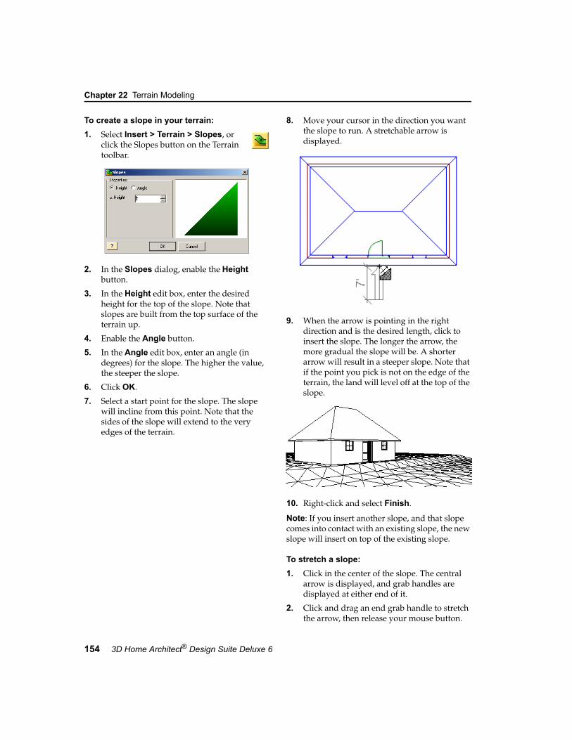
Chapter 22 Terrain Modeling
154 3D Home Architect® Design Suite Deluxe 6
To create a slope in your terrain:1. Select Insert > Terrain > Slopes, or
click the Slopes button on the Terrain toolbar.
2. In the Slopes dialog, enable the Height button.
3. In the Height edit box, enter the desired height for the top of the slope. Note that slopes are built from the top surface of the terrain up.
4. Enable the Angle button.
5. In the Angle edit box, enter an angle (in degrees) for the slope. The higher the value, the steeper the slope.
6. Click OK.
7. Select a start point for the slope. The slope will incline from this point. Note that the sides of the slope will extend to the very edges of the terrain.
8. Move your cursor in the direction you want the slope to run. A stretchable arrow is displayed.
9. When the arrow is pointing in the right direction and is the desired length, click to insert the slope. The longer the arrow, the more gradual the slope will be. A shorter arrow will result in a steeper slope. Note that if the point you pick is not on the edge of the terrain, the land will level off at the top of the slope.
10. Right-click and select Finish.
Note: If you insert another slope, and that slope comes into contact with an existing slope, the new slope will insert on top of the existing slope.
To stretch a slope:1. Click in the center of the slope. The central
arrow is displayed, and grab handles are displayed at either end of it.
2. Click and drag an end grab handle to stretch the arrow, then release your mouse button.
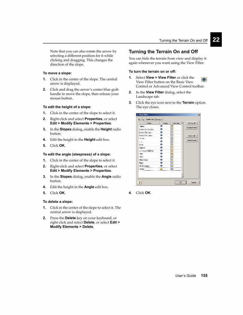
Turning the Terrain On and Off
User’s Guide 155
22
Note that you can also rotate the arrow by selecting a different position for it while clicking and dragging. This changes the direction of the slope.
To move a slope:1. Click in the center of the slope. The central
arrow is displayed.
2. Click and drag the arrow’s center blue grab handle to move the slope, then release your mouse button.
To edit the height of a slope:1. Click in the center of the slope to select it.
2. Right-click and select Properties, or select Edit > Modify Elements > Properties.
3. In the Slopes dialog, enable the Height radio button.
4. Edit the height in the Height edit box.
5. Click OK.
To edit the angle (steepness) of a slope:1. Click in the center of the slope to select it.
2. Right-click and select Properties, or select Edit > Modify Elements > Properties.
3. In the Slopes dialog, enable the Angle radio button.
4. Edit the height in the Angle edit box.
5. Click OK.
To delete a slope:1. Click in the center of the slope to select it. The
central arrow is displayed.
2. Press the Delete key on your keyboard, or right-click and select Delete, or select Edit > Modify Elements > Delete.
Turning the Terrain On and OffYou can hide the terrain from view and display it again whenever you want using the View Filter.
To turn the terrain on or off:1. Select View > View Filter or click the
View Filter button on the Basic View Control or Advanced View Control toolbar.
2. In the View Filter dialog, select the Landscape tab.
3. Click the eye icon next to the Terrain option. The eye closes.
4. Click OK.


157
Chapter
You may want to know where your property lines are, especially if you are working in a confined or unusually-shaped area. Lot lines and setbacks can be found on a survey plan or surveyor’s certificate.
Using the Site Boundary tool you can define and insert a site boundary, which shows your property lines, stakes, and building setbacks.
Site Boundary
Property Lines

Chapter 23 Property Lines
158 3D Home Architect® Design Suite Deluxe 6
Defining Your Building LotYou can use the Site Boundary tool to insert a site boundary in your 2D plan. A site boundary consists of two continuous lines: one that shows the legal property boundary (lot lines), and one that defines the building envelope (setbacks). The site boundary can be annotated with peg markers, bearing text, length text and peg numbers. It will only appear in 2D wireframe view.
The catalog contains some pre-defined site boundaries that you can edit to suit your needs. You can also create a new site boundary element from scratch if you prefer.
Note: Site boundaries are visible in 2D plan view only.
To insert a site boundary:
1. In 2D plan view, select View > Zoom and Navigate > Zoom to Fit, or click the Zoom to Fit button on the Basic View Control or Advanced View Control toolbar. This will bring the entire terrain into view so you can insert the boundary easily and precisely.
2. Select Insert > Terrain > Site Boundary, or click the Site Boundary button on the Terrain toolbar.
3. In the catalog, select the boundary you want to insert. If you want to create a custom site boundary, right-click the lot that is closest to the one you want to create, then select Catalog Manager. See Defining a Custom Building Lot on page 159. You can also insert a lot for now and edit it later if you want.
4. Position the boundary where you want it, then click to insert it.
5. Right-click and select Finish.
Tip: You can put a fence along your lot lines to show where the lot lines are in 3D. See Inserting a Fence on page 164.
To move the site boundary:1. Click on one of your lot lines to select the
entire site boundary. A blue grab handle is displayed at the center of the site boundary.
2. Hover your pointer over the center blue grab handle to display the Move cursor.
3. Click and drag to move the boundary, then release your mouse button.
To edit the site boundary:1. Click on one of your lot lines to select the
entire site boundary.
2. Right-click and select Properties, or select Edit > Modify Elements > Properties.
3. Make your changes in the Site Boundary dialog, then click OK. For more information about site boundary properties, see Defining a Custom Building Lot on page 159.
To delete the site boundary:1. Click on one of your lot lines to select the
entire site boundary.
Lot Line
Setback Line
Peg (stake)

Defining a Custom Building Lot
User’s Guide 159
23
2. Press the Delete key on your keyboard, or right-click and select Delete, or select Edit > Modify Elements > Delete.
Defining a Custom Building LotIf the building lot you want to insert is not available in the catalog, you can create a custom one on the fly. Defining a site boundary involves entering a bearing and length from one peg to the next. This information can be found on a survey plan or surveyor’s certificate.
To define a custom building lot:1. If you haven’t already accessed the Catalog
Manager, select File > Catalogs > Catalog Manager.
2. In the Catalog Manager, make sure Site Boundary is selected in the Element drop box.
3. In the Select a Type window, select the group you want to add the site boundary to (Rectangle Lots, Pie Shape Lots or Square Lots). If your boundary has an unusual shape, you may want to create a new group for it.
4. Select Catalog > Add Element.
5. In the Site Boundary dialog, click Clear All.6. Type a name for your boundary in the Name
edit box.
7. On the Basic property page, click the Direction drop box, then select the method you want to use to define your lot lines.
The Ref. angle option lets you define lot lines using compass points (N, S, E, W) and specifying a reference angle in degrees, minutes and seconds (e.g. 5d12’10”). The Angle bearing option lets you use angles to specify a forward and back bearing.
8. Define your first lot line by filling in the fields in the parameters window, then clicking Add. The line appears in the preview window, and its properties appear in the Segments window.
9. Continue defining lot lines. When you are ready to define the last lot line, just check the Closing check box, then click Add. This closes the last line created back to the first line.
• To edit an existing lot line, select it in the upper window, edit its parameters in the lower window, then click Update.
• To delete a lot line, select it in the upper window, then click Delete.
• To delete all existing lot lines, click Clear All.
10. Once you’ve defined the size and shape of the site boundary, select the Annotation tab in the Site Boundary dialog.

Chapter 23 Property Lines
160 3D Home Architect® Design Suite Deluxe 6
11. Specify the desired annotation settings. You can choose round or square peg markers, and specify the marker’s diameter. You can also choose to include bearing text, length text and peg text (numbers), as well as specify the position and style for the text.
83’-4” @ N 90d00’00” E
12. Once your lot lines are defined, click OK. The boundary is added to the current catalog.
13. Click OK. You can now insert the boundary in your drawing.

Fences & Gates page 163
Decks & Patios page 171
Retaining Walls page 185
Sidewalks, Pathways & Driveways page 189
Working on the Exterior of Your Home
Part 7


163
Chapter
Fences can add beauty, privacy and security to your property. Fences are drawn with ease in 3D Home Architect® Design Suite. Just point and click to fence off a yard in seconds!
The catalog contains an assortment of fences in a variety of materials, including concrete, stone and wood. You can even add a white picket fence for that classic look.
Once you’ve drawn your fence you can easily pop a gate into it. You can choose a style that matches your fence, or choose an entirely different style to create a stylish accent.
Fences & Gates

Chapter 24 Fences & Gates
164 3D Home Architect® Design Suite Deluxe 6
Inserting a FenceTo insert a fence, you draw it just like a wall by selecting a start point and end point. This allows you to create a fence of any length. You can continue selecting points in other directions to add on to the fencing (if you want to fence around your yard, for example).
Tip: If you have inserted a site boundary in your plan, you can draw your fence on top of the lot lines for ease. The fence then acts as a visual indicator of your property extents in 3D.
To insert a fence:
1. Select Insert > Landscape > Fences/Gates > Fences, or click the Fences/Gates button on the Landscape toolbar and select Fences.
2. In the catalog, select the fence type you want to insert.
3. Select a start point for the fence.
4. Move your cursor in the direction you want the fence to run. The fence stretches as you move your cursor.
5. Select an end point for the fence. If you want you can continue adding sections to the fence in any direction by simply selecting points.
6. Right-click and select Finish.
12
3 4
556

Stretching a Fence Layout
User’s Guide 165
24
Stretching a Fence LayoutYou can stretch a fence layout by clicking and dragging one of the fence segments.
To stretch a fence layout:1. Click on the fence segment you want to
move.
2. Position your pointer over the center blue grab handle to display the Move cursor.
3. Click and drag to stretch the layout, then release your mouse button.
Changing the Length of a Fence You can lengthen or shorten a fence by clicking and dragging its end points.
To change the length of a fence:1. Select the fence you want to lengthen or
shorten.
2. Click and drag one of the fence’s end handles to stretch the fence, then release your mouse button.
Creating a Break in a FenceWhen you create a break in a fence, you can select the fence portions on either side of the break independently. You may want to insert one or more breaks in a fence so that you can then remove certain segments of it.
To create a break in a fence:1. Select the fence you want to break.
2. Right-click and select Break, or select Edit > Modify Elements > Break.
3. Double-click where you want to break the fence.
Parts of a Fence
Editing the Properties of a FenceYou can change the height of a fence, specify whether or not you want the fence to hug the terrain, edit the size and position of fence posts, and edit the dimensions of the rails and boards.
To edit the properties of a fence:1. Click on the fence to select it.
2. Right-click and select Properties, or select Edit > Modify Elements > Properties.
Post
Secondary PostBoards
Rails

Chapter 24 Fences & Gates
166 3D Home Architect® Design Suite Deluxe 6
3. To change the type of fence, click on the appropriate graphic in the Type area. Choose from General, Privacy, Picket or Ranch. The General style just inserts a plain, flat surface.
4. To change the height of the fence, edit the values in the Fence Height edit box.
5. If you want the bottom of the fence to hug the terrain, check the Hug Terrain? check box, then select either Raked or Stepped from the Slope Type drop box.
6. To change the dimensions or position of the fence posts, edit the parameters in the Posts area.
Secondary Post Position. Choosing Centered starts the spacing of intermediate posts from the middle of the fence to create a balanced look. Choose From Start starts the
spacing of intermediate posts from the first main post.
Max. Post Spacing. The maximum allowable spacing between posts. If you stretch the fence, the spacing between posts increases. More posts are added to prevent the spacing from exceeding the maximum.
Post Width. The width (and depth) of fence posts.
Post Extension. The distance the fence posts extend past the top of the fence boards.
Post Rotation. Determines the rotation of the connecting post where two fence segments connect. Choosing Half Way rotates the connecting post half way between the angle. Choosing None leaves the connecting post aligned to the first fence.
7. To change the dimensions of the top, middle or bottom rail, edit the parameters in the Rails area.
Rail Width. The width of the rail members.
Rail Depth. The thickness of the rail members.
Top Rail Height. The distance from the bottom of the fence to the top rail.
Middle Rail Height. The distance from the top rail to the middle rail.
Bottom Rail Height. The distance from the middle rail to the bottom rail.
8. To change the dimensions of the boards in a privacy or picket fence, edit the parameters in the Boards area.
Board Style. Choose either Squared or Pointed. You would typically see pointed boards on a picket fence.
Board Width. The width of one fence board.
Board Depth. The thickness of one fence board.
Board Spacing. The distance from the center of one board to the center of the next board.
Board Offset. The offset of the bottom of the fence boards from the ground.
Raked
Stepped

Changing the Fencing Material
User’s Guide 167
24
9. When you’re done editing properties, click OK.
Changing the Fencing MaterialYou can apply a different color or material to the boards, posts or rails of a fence. For example, you can select a different type of wood for a wood fence.
To apply different materials to a fence:1. Display your model in 3D, and make sure the
fence is visible in the view.
2. Select Edit > Materials Paintbrush, or click the Materials Paintbrush button on any tabbed toolbar.
3. In the catalog panel, select the material you want to apply.
4. Click on the fence component you want to apply the material to. Materials are applied separately to the individual parts of the fence (fence boards, posts and rails). Clicking on one component will apply the material to all components of the same type. For example, clicking on one post will apply the material to all posts.
5. When you are finished applying materials, right-click and select Finish.
Deleting a FenceYou can delete a fence in a couple of easy steps.
To delete a fence:1. Select the fence. You can select multiple fence
segments using Shift+click.
2. Press the Delete key on your keyboard, or right-click and select Delete, or select Edit > Modify Elements > Delete.
Inserting a GateThe catalog contains a variety of gate types, including wood, picket and ranch style gates. Gates just pop themselves right into fences. Naturally, if you are inserting a gate in a fence, you want to choose a gate size that corresponds to the fence size. For example, if your fence is a 6’ wood privacy fence, you would likely choose the 6’ wood privacy gate. Gates are shown slightly open so you can identify them easily in 2D and 3D views.
To insert a gate:1. Select Insert > Landscape > Fences/Gates
> Gates, or click the Fences/Gates button on the Landscape toolbar and select Gates.
2. In the catalog, select the gate you want to insert.
3. Position the gate where you want it, then click to insert it. The gate will automatically pop itself into the fence when you position it in the fence.

Chapter 24 Fences & Gates
168 3D Home Architect® Design Suite Deluxe 6
4. Right-click and select Finish.
Moving a GateYou can move a gate back and forth inside a fence by simply clicking and dragging it.
To move a gate:1. Click on the gate to select it.
2. Hover your pointer over the center grab handle to display the Move cursor.
3. Click and drag to move the gate, then release your mouse button.
Flipping a GateYou can use the Flip Opening tool to flip an entire gate around. If the gate originally opened out, it now opens in; if it was hinged on the left, it is now hinged on the right (and vice versa).
To flip a gate:1. Click the gate to select it.
2. Right-click in the drawing area and select Flip Opening, or select Edit > Modify Elements > Flip Opening.
Flipping a Gate’s SwingUse the Flip Swing tool to flip only the swing of a gate. The gate will be hinged on the opposite side, but it will still open in the same direction, either in or out.
To flip a gate swing:1. Click the gate to select it.
2. Right-click in the drawing area and select Flip Swing, or select Edit > Modify Elements > Flip Swing.
Editing the Properties of a GateYou can change the height and width of a gate as well as the dimensions of the rails and boards. You can also control how far the gate is open in 2D and 3D views.
To edit the properties of a gate:1. Click on the gate to select it.
2. Right-click and select Properties, or select Edit > Modify Elements > Properties.
3. To change the type of gate, click on the appropriate graphic in the Type area. Choose from General, Privacy, Picket or Ranch. The General style just inserts a plain, flat door.
4. To change the overall size of the gate, edit the values in the Gate Width and Gate Height edit boxes.
5. To change the swing type, select either Left or Right from the Swing Type drop box. This determines which side the gate is hinged on.
6. If you want to change how far the gate is open in 3D views, edit the percentage in the 3D Percent Open edit box. To change how far the gate is open in 2D views, change the percentage in the 2D Percent Open edit box.

Deleting a Gate
User’s Guide 169
24
7. To change the dimensions of the top, middle or bottom rail, edit the parameters in the Rails area.
Rail Width. The width of the rail members.
Rail Depth. The thickness of the rail members.
Top Rail Height. The distance from the bottom of the gate to the top rail.
Middle Rail Height. The distance from the top rail to the middle rail.
Bottom Rail Height. The distance from the middle rail to the bottom rail.
8. To change the dimensions of the boards in a privacy or picket fence, edit the parameters in the Boards area.
Board Style. Choose either Squared or Pointed. You would typically see pointed boards on a picket fence.
Board Width. The width of one fence board.
Board Depth. The thickness of one fence board.
Board Spacing. The distance from the center of one board to the center of the next board.
Board Offset. The offset of the bottom of the gate boards from the ground.
9. When you’re done editing properties, click OK.
Deleting a GateYou can delete a gate in a couple of easy steps. When you delete a gate, the fence returns to its original state.
To delete a gate:1. Select the gate.
2. Press the Delete key on your keyboard, or right-click and select Delete, or select Edit > Modify Elements > Delete.


171
Chapter
A great way to add more living space to your home without building an addition is to build a deck or patio. With outdoor living spaces becoming more and more desirable, 3D Home Architect® Design Suite gives you all the tools you need to create the exact look you want, quickly and easily.
The Deck Builder Wizard makes building a deck so simple — just select the material and shape you want, and the deck is built for you automatically. Or if you prefer, you can create the precise size and shape you want using the Deck tool. You can even add levels to your deck if you want for a truly customized look. Once you’ve got the main platform up, you can point and click to insert stairs of your choice.
Creating a patio involves clicking a few points to define the outline of the slab using the Pads tool.
Decks & Patios

Chapter 25 Decks & Patios
172 3D Home Architect® Design Suite Deluxe 6
Using the Deck Builder WizardThe Deck Builder Wizard takes all the work out of building a deck because it does it all for you! Just select the decking material and deck shape, enter the dimensions you want, then point and click to insert the deck. By default, decks include posts, beams and railings.
After inserting a deck you can move, stretch, rotate, raise or lower it if needed, as well as edit its properties, which include settings for posts, railings and skirting.
To build a deck using the Deck Builder Wizard:1. In the Building Locations drop box, select the
location you want to associate the deck with. The height of a deck is determined by the Height above current location variable in the deck properties. You can edit this value after the deck has been inserted if necessary.
2. Select Tools > Design Wizards > Deck Builder.
3. In the Deck Wizard dialog, click Next.
4. Select the decking material you would like to use.
5. Click Next.
6. In the Shape area, click on the shape that most closely resembles the shape you want to create. Remember that you can edit the shape after the deck has been inserted.
7. In the Size area, specify the desired dimensions for the deck.

Building a Deck with the Deck Tool
User’s Guide 173
25
8. Click Next.
9. In the Deck Rotation area, select the desired rotation for your deck. This is how the deck will be oriented when it is attached to your cursor.
10. In the Decking Direction area, select the direction you want the deck boards to run.
11. Click Next.
12. Click Finish. The Deck Wizard closes, and the deck is attached to your cursor, ready to be inserted.
13. Position the deck where you want it, then click to insert it.
Building a Deck with the Deck ToolYou can use the Deck tool to build a deck of virtually any shape and size. By default, decks include posts and railings. You can opt to include skirting if you want.
Once you’ve inserted a deck you can move, stretch, rotate, raise or lower it if needed, as well as edit its properties, which include settings for posts, railings and skirting.
To create a deck:1. In the Building Locations drop box, select the
location you want to associate the deck with. The height of a deck is determined by the Height above current location variable in the deck properties. You can edit this value after the deck has been inserted if necessary.
2. Select Insert > Landscape > Decks > Decks, or click the Decks button on the Landscape toolbar and select Decks.
3. In the catalog, select the decking material you want to use.
4. Select a start point for the deck outline. Continue selecting points until the outline is defined. (You do not have to select the start point again because the last point you pick is always closed back to the start point.)
1
2 3
4

Chapter 25 Decks & Patios
174 3D Home Architect® Design Suite Deluxe 6
5. Right-click and select Finish.
Moving a DeckYou can move a deck using the Move Whole Element tool.
To move a deck:1. Click on one of the deck’s edges to select the
deck.
2. Right-click and select Move Whole Element, or select Edit > Modify Elements > Move Whole Element. Alternatively you can Shift+click to select the remaining edges.
3. Click and drag the deck to move it.
4. Release your mouse button.
Rotating a DeckYou can use the Rotate tool to rotate a deck about a selected point.
To rotate a deck:1. Select the deck by clicking on one of its
edges. A grab handle is displayed at each corner.
2. Right-click and select Rotate, or select Edit > Modify Elements > Rotate.
3. Hover your pointer over the point you want to rotate around.
4. Click and drag to rotate the deck, then release your mouse button.
Note: When you rotate a deck, the direction of the deck boards does not change. You can change the decking direction if you want.
Changing the Direction of Deck BoardsYou can use the Set Decking Direction tool to change the direction of your deck boards.
To change the direction of deck boards:1. Select the deck by clicking on one of its
edges.
2. Right-click and select Set Decking Direction, or select Edit > Modify Elements > Set Decking Direction.
3. Select two points to define a line that runs in the direction you want the deck boards to run. The deck boards update to match the direction of the line.
Stretching a DeckYou can stretch a deck in any direction by clicking and dragging one of its edges.
To stretch a deck:1. Click on the deck edge you want to stretch.
2. Hover your pointer over the center blue grab handle to display the Move cursor.
3. Click and drag to stretch the deck, then release your mouse button.
Reshaping a DeckYou can change the shape of a deck by stretching any of its corners.
To reshape a deck:1. Click on the deck to select it. A grab handle is
displayed at each corner.
2. Click and drag a corner grab handle to stretch the deck.
3. Release your mouse button.
Curving a Deck EdgeYou can curve a deck edge using the Curve tool. Once the tool is active, you can click and drag the deck edge to curve it, or select a point to curve to.
To curve a deck edge by clicking and dragging:1. Click on the deck edge you want to curve.
2. Right-click and select Curve, or select Edit > Modify Elements > Curve.
3. Click and drag the deck edge to the desired curve.
4. Release your mouse button.
Changing the Height of a Deck
User’s Guide 175
25
To curve a deck edge to a selected point:1. Click on the deck edge you want to curve.
2. Right-click and select Curve, or select Edit > Modify Elements > Curve.
3. Select the point you want to curve to. The deck edge automatically curves to the point.
4. Click to finish.
Changing the Height of a DeckBy default, decks are inserted at the floor level of the current building location.
To change the height of a deck:1. Select the deck by clicking on one of its
edges.
2. Right-click and select Properties, or select Edit > Modify Elements > Properties.
3. On the Support property page, edit the value in the Height above current location edit box.
4. Click OK.
Editing Deck Post PropertiesBy default, the support system of a deck consists of 4”x4” wood posts spaced 8’ apart. Posts are sunken 3’-6” into the ground for adequate support. You can edit the post type, post spacing and post depth. You can also disable posts altogether if you want.
To edit deck post properties:1. Select the deck by clicking on one of its
edges.
2. Right-click and select Properties, or select Edit > Modify Elements > Properties.
3. In the Decks dialog, select the Support tab.
4. If you want to remove posts from the deck, uncheck the Include Posts check box in the Posts area.
5. To select a different member to use for deck posts, click the Select button in the Posts area, then make your selection from the catalog.
6. To change the spacing between posts along beams, edit the value in the Spacing along Beam edit box.
7. To change the depth of the posts in the ground, edit the value in the Depth below ground level edit box. This effectively changes the overall height of the post, but does not affect the portion shown above ground.
8. Click OK.
Displaying Footings Under Deck PostsFootings are not included in your deck by default, but you can display them instantly by editing deck properties. You can also choose the footing material you want to use.
To create footings under deck posts:1. Select the deck by clicking on one of its
edges.
2. Right-click and select Properties, or select Edit > Modify Elements > Properties.
3. On the Support property page, check the Include Footings check box in the Footings area.
4. Click the Select button in the Footings area, then select the desired footing type from the catalog.
5. Click OK.
Editing the Deck FrameYou have complete control over the way a deck is constructed. You can specify the way you want the beams constructed in relation to the posts. You can also select specific materials to use for deck boards, beams and joists, as well as edit the spacing and overhang of these members.
To edit the deck frame:1. Select the deck by clicking on one of its
edges.
2. Right-click and select Properties, or select Edit > Modify Elements > Properties.

Chapter 25 Decks & Patios
176 3D Home Architect® Design Suite Deluxe 6
3. In the Decks dialog, select the Frame tab.
4. To change the way the beams are constructed, click on the desired configuration in the Construction area. Beams are the vertical members that rest on or are attached to the posts, and that support the deck joists.
5. To select a different material for the deck boards, click the Select button in the Decking area, then make your selection from the catalog.
6. To edit the spacing between deck boards, edit the value in the Spacing edit box in the Decking area.
7. To change the amount the deck boards hang over the deck frame, edit the value in the Overhang edit box in the Decking area.
8. To adjust the angle of the deck boards in relation to the joists, edit the value in the Angle from Joists edit box.
9. To select a different material for the deck joists, click the Select button in the Joists area, then make your selection from the catalog.
10. To edit the spacing between joists, edit the value in the Spacing edit box in the Joists area.
11. To change the amount the joists hang over the beams, edit the value in the Overhang edit box in the Joists area. The general rule of
thumb is to limit the extension to 1/3 of their length.
12. To select a different material for the deck beams, click the Select button in the Beams area, then make your selection from the catalog.
13. To change the amount the beams extend past each other, edit the value in the Overhang edit box in the Beams area.
14. Once you’ve specified the deck frame properties, click OK.
Changing the Railing StyleYou can change a deck’s railing type by making a selection on the Accessories property page.
To change a deck’s railing style:1. Select the deck by clicking on one of its
edges.
2. Right-click and select Properties, or select Edit > Modify Elements > Properties.
3. In the Decks dialog, select the Accessories tab.
4. In the Railings area, click the Select button.
5. Select the desired railing type from the catalog.
6. Click OK.

Controlling the Display of Deck Railings
User’s Guide 177
25
Controlling the Display of Deck RailingsYou can delete railings from selected deck edges to provide access to the deck. If you want to remove all the railings on a deck, you need to select all of the decks edges first.
To control the display of deck railings:1. Click on the deck edge you want to remove a
railing from, or add a railing to. A blue grab handle is displayed at the center of the selected deck edge. If you want to remove railings from other edges as well, use Shift+click to select the additional edges.
2. Right-click and select Properties, or select Edit > Modify Elements > Properties.
3. In the Decks dialog, select the Accessories tab.
4. Disable the Include railing on selected edges check box.
5. Click OK.
Note: If you add stairs to your deck, an opening will be automatically created in the railing.
Controlling the Display of Deck SkirtingSkirting is basically screening along the bottom of a deck that conceals the underside of the deck frame. It can also keep out animals and debris. Most decks display skirting. You can choose to turn skirting off if you want. If displaying skirting, you can select the skirting material you want to use, such as lattice.
To display skirting on your deck:1. Select the deck by clicking on one of its
edges.
2. Right-click and select Properties, or select Edit > Modify Elements > Properties.
3. In the Decks dialog, select the Accessories tab.
4. If you want to display skirting on your deck, check the Include skirting on selected edges check box.
5. Click the Select button in the Skirting area, then select the desired skirting material from the catalog.
6. Click OK.
Inserting Openings in a DeckOnce you have created a deck, you can insert a custom opening in it of virtually any shape and size using the Cut Opening tool.
You create the opening by picking points to define its outline.
To insert an opening in a deck:1. Select the deck by clicking on one of its
edges.
2. Right-click and select Cut Opening, or select Edit > Modify Elements > Cut Opening.
3. Select a start point for the opening.
4. Continue selecting points to define the opening. As you select points, the opening is created. The last point picked is always connected back to the start point to form a closed shape, so you don’t have to pick the start point again.

Chapter 25 Decks & Patios
178 3D Home Architect® Design Suite Deluxe 6
5. When you have selected your final point, right-click and select Finish.
Resizing a Deck OpeningYou can resize a deck opening by clicking and dragging one of its edges.
To stretch a deck opening:1. Click on the opening edge you want to move.
The entire opening is highlighted, and a blue grab handle appears at the center of the opening edge you selected.
2. Hover your pointer over the center grab handle to display the Move cursor.
3. Click and drag in the direction you want to stretch.
4. When the opening is the correct size, release your mouse button.
Reshaping a Deck OpeningYou can change the shape of a deck opening by stretching its corners. You can do this by clicking and dragging.
To reshape a deck opening by stretching:1. Click on the opening to select it. A grab
handle is displayed at each corner.
2. Click and drag a corner grab handle to stretch the opening.
3. Release your mouse button.
Curving a Deck Opening EdgeYou can curve an opening edge using the Curve tool. Once the tool is active, you can click and drag the opening edge to curve it, or select a point to curve to.
To curve an opening edge by clicking and dragging:1. Click on the opening edge you want to curve.
2. Right-click and select Curve, or select Edit > Modify Elements > Curve.
3. Click and drag the opening edge to the desired curve.
4. Release your mouse button.
To curve an opening edge to a selected point:1. Click on the opening edge you want to curve.
2. Right-click and select Curve, or select Edit > Modify Elements > Curve.
3. Select the point you want to curve to. The opening edge automatically curves to the point.
4. Click to finish.
Removing Deck OpeningsYou can remove an opening from a deck by selecting all sides of the opening, then clicking and dragging it away from the deck.
Note: You cannot remove an opening using Delete.
To remove a deck opening:1. Click on one of the opening’s edges.
2. Shift+click to select the remaining sides.
3. Hover your pointer over one of the grab handles to display the Move cursor.
4. Click and drag the opening off the deck until it disappears.
Deleting a DeckYou can remove a deck completely in a couple of easy steps.
To remove a deck:1. Click on one of the deck’s edges to select the
deck.
2. Press the Delete key on your keyboard, or right-click and select Delete, or select Edit > Modify Elements > Delete.
Note: If you added stairs to your deck, you need to remove them separately.
Adding Stairs to a DeckYou can add a staircase to your deck with a single mouse click. Stairs automatically snap to your deck for easy insertion, and the railings on the deck are automatically removed to allow for the stair opening. By default, stairs extend from the

Moving Deck Stairs
User’s Guide 179
25
deck platform to down to the terrain, so there’s absolutely nothing you need to calculate. Also, deck stairs have a railing on both sides by default, but you can remove one or both of them if you want after the stairs have been inserted.
You can choose either pressure treated or cedar stairs, and edit the stair dimensions to get the exact result you want.
To add stairs to a deck:
1. Select Insert > Landscape > Decks > Deck Stairs, or click the Decks button on the Landscape toolbar and select Deck Stairs.
2. In the catalog, select the type of stairs you would like to insert.
3. Move your pointer close to the deck edge. Position the stairs where you want them, then click to insert them.
4. Right-click and select Finish.
Moving Deck StairsYou can move a deck staircase by clicking and dragging it along the deck edge. Note that you can’t move deck stairs away from the deck, but you can move them to another deck edge. Also, the opening in the deck railing adjusts with the move of the deck stairs.
To move a staircase by clicking and dragging:1. Click on the staircase to select it.
2. Hover your pointer over the center grab handle to display the Move cursor.
3. Click and drag the staircase along the deck edge to move it.
4. Release your mouse button.
Parts of a Staircase
Editing the Size of Deck StairsYou can edit the overall height and width of deck stairs, the width of the steps, and the riser height.
To edit the size of deck stairs:1. Click on the staircase to select it.
2. Right-click and select Properties, or select Edit > Modify Elements > Properties.
3. Edit the properties on the Basic tab.
Extend Stair. The option selected determines where the base of the stairs sit. You can either change where they extend to, or specify an explicit height. By default, the deck stairs are
Stringer
Nosing
Riser
Tread

Chapter 25 Decks & Patios
180 3D Home Architect® Design Suite Deluxe 6
inserted at deck level and run down to the terrain.
Down to terrain. Extends the stairs down to the ground.
Down to previous location. Extends the stairs to the floor level of the building location below the current one.
Down to deck location. Extends the stairs down to the floor level of the building location the deck is associated with. You might use this if you have raised your deck above the floor level of the current location and want to extend the stairs down.
Explicit Height. Extends the stairs down a specific distance that you define in the Overall Height edit box.
Overall Height. Available only if Explicit Height is selected in the Extend Stair drop box, this lets you define a fixed height for the stairs.
Max. Riser Height. The maximum distance allowed between individual steps. Note that if your riser height exceeds the width of the member you are using for your riser boards, two or more boards will be inserted for each riser.
Tread Run. The width of each step. The width of a step is measured from the nose of the step to the riser of the next step. Note that if your tread run exceeds the width of the member you are using for your treads, two or more boards will be inserted for each step.
Overall Width. The width of the stairs measured from one end of a step to the other end of the step.
Controlling the Display of Railings on Deck StairsBy default, deck stairs have a railing on both sides. You can choose to have a railing on the left side only or right side only, or remove them altogether.
To remove railings from deck stairs:1. Click on the staircase to select it.
2. Right-click and select Properties, or select Edit > Modify Elements > Properties.
3. In the Railings area, uncheck the Include Railings check box if you don’t want any railings on your deck stairs. If you want one or more railings on the stairs, leave this check box enabled.
4. If you want a railing on the left side of the stairs, select Railing on left side from the drop box. If you want a railing on the right side of the stairs, select Railing on right side from the drop box. If you want a railing on both sides of the stairs, select Railing on both sides.
5. Click OK.
Editing Stringers, Risers and TreadsYou can specify detailed settings for the stringers, risers and treads on your deck stairs.
To edit stringer, riser or tread details:1. Click on the staircase to select it.
2. Right-click and select Properties, or select Edit > Modify Elements > Properties.
3. In the Deck Stairs dialog, select the Details tab.

Deleting Deck Stairs
User’s Guide 181
25
4. To change the stringer style, click the appropriate graphic in the Stringer area. Choose from Notched, Stringer and Side.
5. Edit the remaining properties as desired. They are described below.
Stringer
Spacing. The spacing between the outside stringers and intermediate stringers.
Height. The distance from the bottom of the stringer to the underside of the tread/riser intersection. Specifying a stringer height that is the same as the overall height of the staircase creates a staircase that is completely closed on the sides. In other words, the stringers go right to the ground.
Width. The thickness of the stringer members.
Riser
Closed Riser. Inserts riser boards under the steps. If you leave this disabled, the staircase will be open under the treads.
Select. Click this button to select a riser board to use.
Spacing. When the riser comprises two or more boards, this is the spacing between the boards.
Angle. The tilt of the riser boards. A value of 0 means the board is perpendicular to the step (straight up and down). A value above 0
tilts the riser down toward the back of the staircase. The maximum angle allowed is 20º.
Tread
Select. Click this button to select the type of wood to use for your steps.
Spacing. When each step comprises two or more boards, this is the spacing between those boards.
Nosing. The distance the step extends past the riser.
Overhang.The distance the ends of the steps extend past the outer stringers.
6. Click OK.
Deleting Deck StairsYou can delete a set of stairs in a couple of easy steps.
To delete deck stairs:1. Click on the stairs.
2. Press the Delete key on your keyboard, or right-click and select Delete, or select Edit > Modify Elements > Delete.
Creating a PatioYou can use the Pads tool to insert a concrete, brick or wood patio directly on your terrain. By drawing the outline of the patio, you control its precise size and shape.
By default, patio slabs hug the terrain they are inserted on. If the terrain is not flat where you are inserting the patio, you may want to turn off the slab’s Hug Terrain option. This makes the slab flat and positions it at the Terrain Base Level specified in your Terrain Settings.
Height = 12” Height = 4’
0º 20º
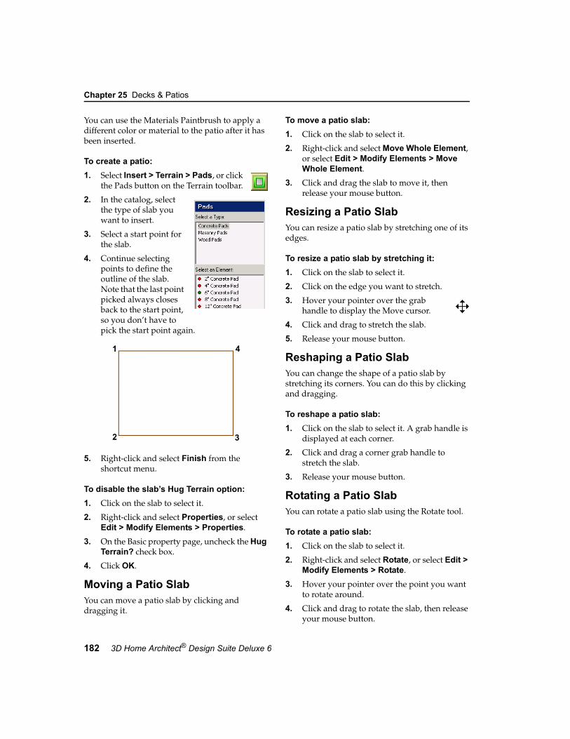
Chapter 25 Decks & Patios
182 3D Home Architect® Design Suite Deluxe 6
You can use the Materials Paintbrush to apply a different color or material to the patio after it has been inserted.
To create a patio:1. Select Insert > Terrain > Pads, or click
the Pads button on the Terrain toolbar.
2. In the catalog, select the type of slab you want to insert.
3. Select a start point for the slab.
4. Continue selecting points to define the outline of the slab. Note that the last point picked always closes back to the start point, so you don’t have to pick the start point again.
5. Right-click and select Finish from the shortcut menu.
To disable the slab’s Hug Terrain option:1. Click on the slab to select it.
2. Right-click and select Properties, or select Edit > Modify Elements > Properties.
3. On the Basic property page, uncheck the Hug Terrain? check box.
4. Click OK.
Moving a Patio SlabYou can move a patio slab by clicking and dragging it.
To move a patio slab:1. Click on the slab to select it.
2. Right-click and select Move Whole Element, or select Edit > Modify Elements > Move Whole Element.
3. Click and drag the slab to move it, then release your mouse button.
Resizing a Patio SlabYou can resize a patio slab by stretching one of its edges.
To resize a patio slab by stretching it:1. Click on the slab to select it.
2. Click on the edge you want to stretch.
3. Hover your pointer over the grab handle to display the Move cursor.
4. Click and drag to stretch the slab.
5. Release your mouse button.
Reshaping a Patio SlabYou can change the shape of a patio slab by stretching its corners. You can do this by clicking and dragging.
To reshape a patio slab:1. Click on the slab to select it. A grab handle is
displayed at each corner.
2. Click and drag a corner grab handle to stretch the slab.
3. Release your mouse button.
Rotating a Patio SlabYou can rotate a patio slab using the Rotate tool.
To rotate a patio slab:1. Click on the slab to select it.
2. Right-click and select Rotate, or select Edit > Modify Elements > Rotate.
3. Hover your pointer over the point you want to rotate around.
4. Click and drag to rotate the slab, then release your mouse button.
2 3
1 4

Editing the Thickness of a Patio Slab
User’s Guide 183
25
Editing the Thickness of a Patio SlabYou can edit the thickness of a patio slab on the slab’s Basic property page.
To edit the thickness of a patio slab:1. Click on the slab to select it.
2. Right-click and select Properties, or select Edit > Modify Elements > Properties.
3. In the Pads dialog, select the Basic tab.
4. Enter the desired thickness in the Thickness edit box.
5. Click OK.
Applying a Different Material to a PatioYou can use the Materials Paintbrush to quickly apply a different color or material to your patio. For example, you may want to change the patio to stone.
To apply a material to a patio:1. Display your model in 3D view and make
sure the patio is visible in the view.
2. Select Edit > Materials Paintbrush, or click the Materials Paintbrush button on any tabbed toolbar.
3. In the catalog panel, select the material you want to apply.
4. Click on the patio surface. The material is immediately applied.
5. Right-click and select Finish.
Deleting a Patio SlabYou can delete a patio slab in a couple of easy steps.
To delete a patio slab:1. Click on the slab to select it.
2. Press the Delete key on your keyboard, or right-click and select Delete, or select Edit > Modify Elements > Delete.


185
Chapter
A well-built retaining wall system can preserve the natural shape of your land, reinforce hills and slopes, and protect your home from possible landslides or soil erosion. Retaining walls can also be an attractive addition to a garden or the overall landscaping around your home.
Drawing retaining walls is easy — just point and click. 3D Home Architect® Design Suite automatically displays dimensions as you draw, and connects corners for you.
Once inserted, any wall can be moved, rotated, lengthened, shortened, broken, curved or deleted. This lets you create the exact wall layout that you want.
The catalog contains wood, concrete and concrete block retaining walls in a variety of sizes. You can change the properties of walls, such as their thickness and appearance, as well as create custom walls.
Retaining Walls

Chapter 26 Retaining Walls
186 3D Home Architect® Design Suite Deluxe 6
Drawing Retaining WallsJust like regular walls, retaining walls are a snap to draw — just point and click.
To draw a retaining wall:1. Select Insert > Terrain > Retaining
Walls, or click the Retaining Walls button on the Terrain toolbar.
2. In the catalog, select the wall type you want to insert.
3. Select a start point for the wall.
4. Move your cursor in the direction you want your wall to run. Its length is shown as you draw the wall.
Note: By default, drawing is constrained to 5º angles. To release this constraint, turn off your Angle Snap.
5. When the wall is the length you want, click to set its endpoint.
6. Continue selecting points to add on to the wall if you want.
7. When you are done, right-click and select Finish.
Editing a Retaining Wall’s Height, Width or ElevationYou can edit the size properties of a wall by making changes on the wall’s Basic property page.
To edit a retaining wall’s size properties:1. Select the wall whose properties you want to
change. You can select multiple walls using Shift+click if you want.
2. Right-click and select Properties, or select Edit > Modify Elements > Properties.
3. In the Walls dialog, select the Basic tab.
4. Edit the properties as desired:
Width. The thickness of the wall.
Wall Height. The physical height of the wall.
Extension Below Base. The height of the wall below the terrain.
5. Once the properties are set, click OK.
Lengthening and Shortening Retaining WallsYou can lengthen or shorten an individual wall by clicking and dragging one of the wall’s ends.
To lengthen or shorten a retaining wall:1. Select the wall. A grab handle is displayed at
each wall end.
2. Hover your pointer over the wall end you want to stretch. The Stretch cursor is displayed.
3. Click and drag the wall end until it has reached the desired length.
4. Release your mouse button.
Rotating a Retaining WallYou can use the Rotate tool to rotate a wall about a selected point.
To rotate a retaining wall:1. Select the wall. A grab handle is displayed at
each wall end.
2. Right-click and select Rotate, or select Edit > Modify Elements > Rotate.
3. Position your pointer over the grab handle you want to rotate the wall around.
4. Click and drag to rotate the wall, then release your mouse button.
Curving a Retaining WallYou can curve a retaining wall using the Curve tool. Once the tool is active, you can click and drag the wall to curve it, or select a point to curve to.
To curve a retaining wall by clicking and dragging:1. Click the wall to select it.

Breaking a Retaining Wall
User’s Guide 187
26
2. Right-click and select Curve, or select Edit > Modify Elements > Curve.
3. Click and drag the wall to the desired curve.
4. Release your mouse button.
To curve a retaining wall to a selected point:1. Click the wall to select it.
2. Right-click in and select Curve, or select Edit > Modify Elements > Curve.
3. Select the point you want to curve to. The wall automatically curves to the point.
4. Click to finish.
Breaking a Retaining WallYou can break a retaining wall into two or more segments using the Break tool. The segments can then be edited individually.
To break a retaining wall:1. Click the wall to select it.
2. Right-click in the drawing area and click Break, or select Edit > Modify Elements > Break.
3. Double-click the point where you want to break the wall. This divides the wall into two segments that can be moved, stretched or manipulated individually.
Applying Different Finishes to Retaining WallsYou can apply different finishes to your retaining walls using the handy Materials Paintbrush. The materials catalog contains an excellent selection of brick, concrete, wood and stone finishes.
To apply a material to a retaining wall:1. Display your model in 3D, and make sure the
wall face you want to apply the material to is visible in the view.
2. Select Edit > Materials Paintbrush, or click the Materials Paintbrush button on any tabbed toolbar.
3. In the catalog panel, select the material you want to apply.
4. Click on the wall face that you want to apply the material to. The material is immediately applied.
5. Right-click and select Finish.
Deleting a Retaining WallYou can delete a retaining wall in a couple of easy steps.
To delete a retaining wall:1. Select the wall to remove. You can select
multiple walls using Shift+click.
2. Press the Delete key on your keyboard, or right-click and select Delete, or select Edit > Modify Elements > Delete.


189
Chapter
Sidewalks, pathways and driveways add to the overall aesthetics of your landscape and provide access to different areas of your property. Drawing them is easy — just select a start point, then point and click in the direction you want the pathway to run. Continue picking points to add segments if you want.
The 3D Home Architect® Design Suite catalog includes an excellent selection of pathway materials including wood, sand, gravel, concrete, brick and asphalt. You can even create a forest path! A number of different widths are available, but you can create a custom width if you want.
Paths
Sidewalks, Pathways & Driveways

Chapter 27 Sidewalks, Pathways & Driveways
190 3D Home Architect® Design Suite Deluxe 6
Drawing Sidewalks, Pathways and DrivewaysThe catalog contains a wide variety of path types, including boardwalks, sand paths, gravel paths, brick paths, and driveways. The width and thickness of a path is determined by the path’s properties in the catalog. You control the length and direction of the path as you draw it. Dimensions are displayed as you draw each segment.
By default, all paths hug the terrain they are inserted on. If the terrain is not flat where you are inserting the path, you may want to turn off the path’s Hug Terrain option. This makes the path flat and positions it at the Terrain Base Level specified in your Terrain Settings.
To create a path:
1. Select Insert > Terrain > Paths, or click the Paths button on the Terrain toolbar.
2. In the catalog, select the path type you want to insert.
3. Select a start point for your path. Note that your insertion point is on the center line of the path.
4. Move your cursor in the direction you want the path to run, then select an endpoint for the path. You can continue selecting points in any direction to add more sections to the path if you want.
Tip: To create a smooth curve in the path, click several points with a short distance between each point.
5. Double-click to finish, or right-click and select Finish.
To disable the path’s Hug Terrain option:1. Click on the path to select it.
2. Right-click and select Properties, or select Edit > Modify Elements > Properties.
3. On the Basic property page, uncheck the Hug Terrain? check box.
4. Click OK.
Stretching a Path ElementYou can lengthen, shorten or rotate a sidewalk, pathway or driveway by clicking and dragging its end or corner grab handles.
If the path has multiple segments, you can also stretch the path layout by moving one of its segments.
To stretch a path by clicking and dragging:1. Select the path. If the path has multiple
segments and you want to stretch the whole path layout by moving a segment, click on the segment you want to move.
Start Point Next Point
Next
Double-clickafter last point
Point
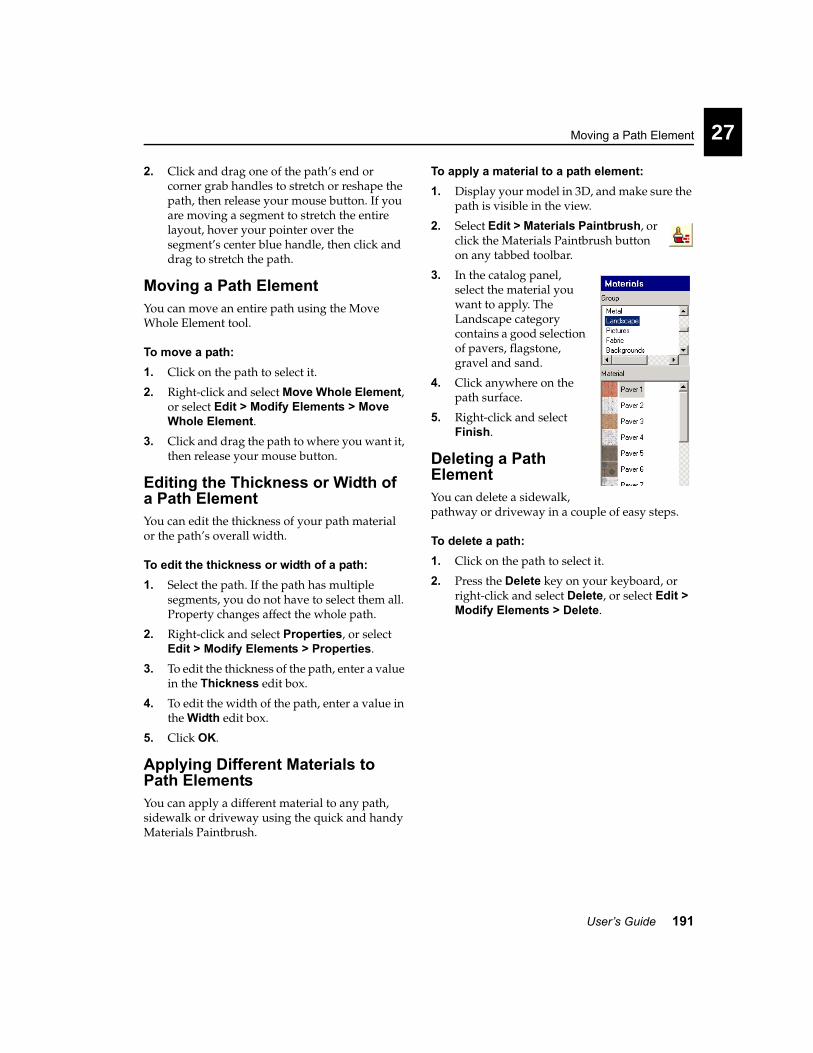
Moving a Path Element
User’s Guide 191
27
2. Click and drag one of the path’s end or corner grab handles to stretch or reshape the path, then release your mouse button. If you are moving a segment to stretch the entire layout, hover your pointer over the segment’s center blue handle, then click and drag to stretch the path.
Moving a Path ElementYou can move an entire path using the Move Whole Element tool.
To move a path:1. Click on the path to select it.
2. Right-click and select Move Whole Element, or select Edit > Modify Elements > Move Whole Element.
3. Click and drag the path to where you want it, then release your mouse button.
Editing the Thickness or Width of a Path ElementYou can edit the thickness of your path material or the path’s overall width.
To edit the thickness or width of a path:1. Select the path. If the path has multiple
segments, you do not have to select them all. Property changes affect the whole path.
2. Right-click and select Properties, or select Edit > Modify Elements > Properties.
3. To edit the thickness of the path, enter a value in the Thickness edit box.
4. To edit the width of the path, enter a value in the Width edit box.
5. Click OK.
Applying Different Materials to Path ElementsYou can apply a different material to any path, sidewalk or driveway using the quick and handy Materials Paintbrush.
To apply a material to a path element:1. Display your model in 3D, and make sure the
path is visible in the view.
2. Select Edit > Materials Paintbrush, or click the Materials Paintbrush button on any tabbed toolbar.
3. In the catalog panel, select the material you want to apply. The Landscape category contains a good selection of pavers, flagstone, gravel and sand.
4. Click anywhere on the path surface.
5. Right-click and select Finish.
Deleting a Path ElementYou can delete a sidewalk, pathway or driveway in a couple of easy steps.
To delete a path:1. Click on the path to select it.
2. Press the Delete key on your keyboard, or right-click and select Delete, or select Edit > Modify Elements > Delete.


LandscapingPart 8
Garden Beds, Ponds & Other Filled Areas page 195
Edging page 199
Trees, Shrubs & Plants page 203
Exterior Structures page 223
Exterior Furniture page 219
Landscape Lighting page 227
Exterior Accessories page 231
Irrigation page 235


195
Chapter
In the real world, one of the first things you need to do to create a garden is to dig out a bed for your plants. In 3D Home Architect® Design Suite, you can create a garden bed instantly by simply picking points to define the outline of the bed. The bed is then automatically filled with a material of your choice, such as soil or bark.
The versatile Fills tool is handy for more than just garden beds. Choose the Water fill to create a pond, or the Sand fill to create a horseshoe pit. The possibilities are endless.
Fills
Garden Beds, Ponds & Other Filled Areas

Chapter 28 Garden Beds, Ponds & Other Filled Areas
196 3D Home Architect® Design Suite Deluxe 6
Creating Filled AreasYou can use the Fills tool to define an area filled with soil, sand, gravel, concrete, bark or water. You define the area by picking points to draw its outline. Filled areas automatically hug the terrain they are inserted on.
To create a filled area:
1. Select Insert > Landscape > Fills, or click the Fills button on the Landscape toolbar.
2. In the catalog, select your fill material.
3. Select a start point for your filled area.
4. Continue selecting points to define the boundary of the filled area. Note that the last point picked always closes back to the start point, so you don’t have to pick the start point again.
5. Right-click and select Finish.
Tip: If you want to create a raised garden you may want to insert a raised garden box from the catalog. See Inserting Exterior Structures on page 224.
Note: You cannot insert a fill on top of another fill.
Resizing a Filled AreaYou can resize a filled area by stretching one of its edges.
To resize a filled area by stretching it:1. Click on the filled area to select it.
2. Click on the edge you want to stretch.
3. Hover your pointer over the solid blue grab handle to display the Move cursor.
4. Click and drag to stretch the fill.
5. Release your mouse button.
Reshaping a Filled AreaYou can change the shape of a filled area by stretching its corners. You can do this by clicking and dragging its grab handles.
To reshape a filled area by stretching:1. Click on the filled area to select it. A grab
handle is displayed at each corner.
2. Click and drag a corner grab handle to stretch the filled area.
2 3
1 4

Rotating a Filled Area
User’s Guide 197
28
3. Release your mouse button.
Rotating a Filled AreaYou can rotate a filled area using the Rotate tool.
To rotate a filled area:1. Click on the filled area to select it.
2. Right-click and select Rotate, or select Edit > Modify Elements > Rotate.
3. Hover your pointer over the corner you want to rotate around.
4. Click and drag to rotate the fill, then release your mouse button.
Moving a Filled AreaYou can move a filled area using the Move Whole Element tool.
To move a filled area:1. Click on the filled area to select it.
2. Right-click and select Move Whole Element, or select Edit > Modify Elements > Move Whole Element.
3. Click and drag the filled area to move it, then release your mouse button.
Changing the Fill MaterialYou can use the Materials Paintbrush to quickly change the look of a fill.
To change the fill material:1. Display your model in 3D, and make sure the
path is visible in the view.
2. Select Edit > Materials Paintbrush, or click the Materials Paintbrush button on any tabbed toolbar.
3. In the catalog panel, select the material you want to apply. The Landscape category contains fill materials like water, sand and gravel.
4. Click anywhere on the surface of the fill. The material is applied immediately.
5. Right-click and select Finish.
Deleting a Filled AreaYou can delete a filled area in a couple of easy steps.
To delete a filled area:1. Click on the filled area to select it.
2. Press the Delete key on your keyboard, or right-click and select Delete, or select Edit > Modify Elements > Delete.
Note: Deleting a fill returns the terrain to its original state where the fill was located.

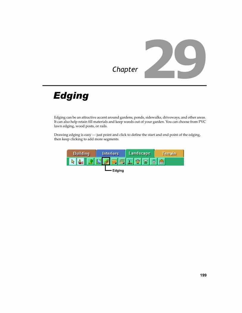
199
Chapter
Edging can be an attractive accent around gardens, ponds, sidewalks, driveways, and other areas. It can also help retain fill materials and keep weeds out of your garden. You can choose from PVC lawn edging, wood posts, or rails.
Drawing edging is easy — just point and click to define the start and end point of the edging, then keep clicking to add more segments.
Edging
Edging

Chapter 29 Edging
200 3D Home Architect® Design Suite Deluxe 6
Inserting EdgingUse the Edging tool to add PVC lawn edging, wood posts, or wood, brick or concrete rails to your landscape design. The width and height of the edging is determined in the material’s properties. You insert edging by simply picking points to define the end points and direction of the edging.
To insert edging:
1. Select Insert > Landscape > Edging, or click the Edging button on the Landscape toolbar.
2. In the catalog, select your edging material.
3. Select a start point for the edging.
4. Move your cursor in the direction you want the edging to run, then select an endpoint for the edging. You can continue selecting points in any direction to add more sections to the edging if you want.
5. Right-click and select Finish.
Tip: You can also insert decorative borders around a garden. See Inserting Exterior Accessories on page 232.
Cleaning Up CornersIf you edged around an area with posts or rails, you’ll notice that the edging members connect on center at the corners. You may want to stretch the corners to form completely flush intersections.
To clean up the corners of edging:1. Click on one of the edging members. Blue
grab handles are displayed at the ends of the member.
2. Hover your pointer over the end grab handle to display the Move cursor.
3
1 4
2

Changing the Length of Edging
User’s Guide 201
29
3. Click and drag the edging so that it meets up with the outside of the member it is connected to, then release your mouse button.
4. Select the other member.
5. Click and drag the end so that it meets up with the inside edge of the connecting member, then release your mouse button.
Changing the Length of EdgingYou can lengthen or shorten edging by clicking and dragging its end points.
To change the length of edging:1. Select the edging you want to lengthen or
shorten. Grab handles are displayed at the center and ends of the edging.
2. Click and drag one of the end grab handles to stretch the edging, then release your mouse button.
Breaking EdgingWhen you create a break in edging, you can select and edit the portions on either side of the break independently.
To create a break in edging:1. Select the edging you want to break.
2. Right-click and select Break, or select Edit > Modify Elements > Break.
3. Double-click where you want to break the edging.
Moving EdgingYou can move a piece of edging by clicking and dragging it. If the member is attached to any other edging members, the other members move along with it.
To move edging:1. Select the edging you want to move. If you
want to move multiple members, use Shift+click to select the other members.
2. Hover your pointer over the center blue grab handle to display the Move cursor.
3. Click and drag to move the edging, then release your mouse button.
Rotating EdgingYou can use the Rotate tool to rotate a wall about a selected point.
To rotate edging:1. Select the edging. A grab handle is displayed
at the center and ends of the edging.
2. Right-click and select Rotate, or select Edit > Modify Elements > Rotate.
3. Hover your pointer over the point you want to rotate around.
4. Click and drag to rotate the edging, then release your mouse button.

Chapter 29 Edging
202 3D Home Architect® Design Suite Deluxe 6
Editing the Height or Width of EdgingYou can edit the height or width (thickness) of edging on the edging’s Basic property page.
To edit the height or width of edging:1. Click on the edging to select it. Use
Shift+click to select multiple segments if necessary.
2. Right-click and select Properties, or select Edit > Modify Elements > Properties.
3. To edit the height of the edging, change the value in the Edge Height edit box.
4. To edit the width (thickness) of the edging, change the value in the Edge Width edit box. Note that this variable is not available for PVC edging.
5. If the edging is post edging, you can control the spacing between posts by editing the value in the Approx. Edge Spacing edit box.
6. Click OK.
Changing the Edging MaterialYou can apply a different color or material to edging using the Materials Paintbrush.
To apply different materials to edging:1. Display your model in 3D, and make sure the
edging is visible in the view.
2. Select Edit > Materials Paintbrush, or click the Materials Paintbrush button on any tabbed toolbar.
3. In the catalog panel, select the material you want to apply.
4. Click on the edging.
5. Right-click and select Finish.
Deleting EdgingYou can delete edging in a couple of easy steps.
To delete edging:1. Select the edging to remove. You can select
multiple edging segments using Shift+click.
2. Press the Delete key on your keyboard, or right-click and select Delete, or select Edit > Modify Elements > Delete.

203
Chapter
Nothing brings your landscape to life like trees, shrubs, plants and flowers. With over 7500 plants to choose from, 3D Home Architect® Design Suite lets you create the landscape of your dreams.
Inserting plants involves nothing more than a single mouse click, and once inserted, they can be dragged and dropped anywhere you like. You can even make them grow!
If you need to learn more about a particular species of plant, you can view the plant’s light, water, temperature and soil requirements in its properties. For even more detailed information you can browse through 3D Home Architect® Design Suite’s comprehensive Plant Encyclopedia.
Plants
Trees, Shrubs & Plants

Chapter 30 Trees, Shrubs & Plants
204 3D Home Architect® Design Suite Deluxe 6
Inserting PlantsPlants are inserted with a simple mouse click. Once inserted, they can be dragged and dropped anywhere in the drawing.
To insert a plant:
1. Select Insert > Landscape > Plants, or click the Plants button on the Landscape toolbar.
2. In the catalog, select the plant you want to insert. If you want to view the plant’s size or requirements before inserting it, right-click in the catalog and select Properties.
3. Position the plant where you want it, then click to insert it.
4. Right-click and select Finish.
Note: Although the catalog contains a wide variety of plants for you to insert, it does not contain all the plants listed in the Plant Encyclopedia. You can, however, add plants from the Encyclopedia to the current catalog. For more information, see Adding a Plant from the Encyclopedia to the Catalog on page 217.
Moving a PlantYou can move a plant easily by just clicking and dragging it.
To move a plant:1. Select the plant you want to move.
2. Hover your pointer over the plant’s center grab handle to display the Move cursor.
3. Click and drag to move the plant.
4. When the plant is where you want it, release your mouse button.
Changing the Elevation of a PlantYou can raise or lower a plant using the Elevate tool. You may want to do this for hanging plants, or plants in raised garden boxes.
To change the elevation of a plant:1. Select the plant.
2. Right-click and select Elevate, or select Edit > Modify Elements > Elevate.
3. In the Elevate dialog, specify the desired elevation of the plant above the ground.
4. Click OK.
Editing the 2D Appearance of a PlantBy default, plants are represented by a circle in 2D plan view. At the center of the circle is a smaller circle that represents the trunk.
You can choose from three 2D plant styles. You can also change the diameter of the trunk in 2D, or hide the trunk altogether.
To edit the style of a plant in 2D:
1. Select the plant whose properties you want to edit.
2. Right-click and select Properties, or select Edit > Modify Elements > Properties.
3. In the Plants dialog, select the Basic tab.
4. To change the style of the circle shown in 2D plan view, click the style you want in the Type area.

Changing the Age of a Plant
User’s Guide 205
30
5. To change the size of the trunk in 2D plan view, edit the value in the Trunk Diameter edit box. To hide the trunk from 2D view, select No from the Show trunk in plan? drop box.
6. Click OK.
Changing the Age of a PlantThe age of a plant determines its size at planting time. You can increase or decrease the age of a plant by making a change on the plant’s Plant Info property page.
To change the age of a plant:1. Click on the plant whose planting age you
want to change.
2. Right-click and select Properties, or select Edit > Modify Elements > Properties.
3. In the Plants dialog, select the Plant Info tab.
4. Move the Planting Age slider left or right until the desired planting age is displayed. Planting age is measured in years.
5. Click OK.
Forcing a Custom Plant SizeThe size of a plant is determined by properties in the Plant Encyclopedia. You can specify a custom height and width for a plant on the plant’s Size property page. Note that if you do this, however,
the plant’s size changes in both 2D and 3D regardless of the Planting Age setting on the Plant Info page.
Note: If you just want to see plants at a different maturity level (i.e. change their age), you should change their planting age instead. See Changing the Age of a Plant on page 205. You can also apply an overall age change to your landscape. See Seeing Plant Growth Over Time on page 206.
To change the size of a plant:1. Select the plant whose properties you want to
edit.
2. Right-click and select Properties, or select Edit > Modify Elements > Properties.
3. In the Plants dialog, select the Size tab.
4. Set the Size from encyclopedia option to No.
5. To change the width of the plant, enter a value in the Width edit box.
6. To change the height of the plant in 3D view, edit the value in the Height edit box.
7. Click OK.

Chapter 30 Trees, Shrubs & Plants
206 3D Home Architect® Design Suite Deluxe 6
Deleting a PlantYou can delete a plant in a couple of easy steps.
To delete a plant:1. Select the plant.
2. Press the Delete key on your keyboard, right-click and select Delete, or select Edit > Modify Elements > Delete.
Seeing Plant Growth Over TimeOnce you have inserted plants in your landscape plan, you can see how they will look any specified number of years down the road using the Plant Growth Over Time feature.
To see plant growth over time:1. Select Tools > Gardening > Plant Growth
Over Time.
2. Enter the number of years to add to your landscape.
3. Click OK.
Applying Seasonal Changes to PlantsThe Plant Seasonal Change feature updates the appearance of the plants in your drawing to reflect a particular season. Generally the change applies to flowering plants and trees that have a certain bloom time.
You specify the season by adjusting the time of year on the Global Settings page of the Program Settings dialog.
To apply seasonal changes to your plants:1. Select Tools > Gardening > Plant Seasonal
Change.
2. In the Program Settings dialog, change the date. Select a month by clicking the arrows on the month bar at the top of the calendar. Select a day by clicking a number on the calendar.
3. Click OK. The plants in your drawing are updated according to the time of year you specified.
Note: Keep in mind that seasonal changes may have different results depending on the plant’s properties in the Encyclopedia. Things to consider are the climate of the region the plant is in, and the plant’s world origin.

Using the Plant Encyclopedia
User’s Guide 207
30
Using the Plant EncyclopediaThe Plant Encyclopedia contains comprehensive information on over 7500 different varieties of plants. The Encyclopedia has many uses related to the selection and care of plants. You can view information about any plant, select plants based on certain criteria, research potential diseases, and learn how to care for your plants.
To access the Plant Encyclopedia, select Tools > Gardening > Plant Encyclopedia.
You can also access the Plant Encyclopedia by clicking the Encyclopedia button on a plant’s Encyclopedia property page.
Plant List
Plant Photo
Select ButtonScroll through the Selects the current
plant for placementin the current catalog
Plant
Plant
Season Color Diagram
Height
Width
Usage Window Plant Info
Search Edit Field Type in the first
few letters of theplant you are looking for
list and select theplant you want toview
Latin/CommonButtonSwitches betweenCommon and Latinplant names
ProfileView
Overhead View
when adding plantsto the catalog

Chapter 30 Trees, Shrubs & Plants
208 3D Home Architect® Design Suite Deluxe 6
The Encyclopedia Main PageThe Encyclopedia’s main page contains a comprehensive plant list that you can scroll through and select plants from. The page also displays a photo and two previews of a selected plant, as well as basic information about the plant and its appropriate growing environment.
Selecting a Plant to ViewBy default, the plant list contains all 7500 plant species. If you have used the Plant Filter to filter out certain plant types, the list is smaller. (For more information about the Plant Filter, see Filtering the Plant List on page 216).
To select a plant in the plant list, use the scrollbar beside the plant list to scroll through the list of plants, then click on the plant you want to view. By default, common plant names are listed in the plant list. You can switch to Latin names by clicking the Latin button.
If you know the name of the plant you are looking for, you can locate it more quickly by typing the first few letters of the plant’s name in the Search Edit field above the plant list. The list of plants will move to the closest match as you type.
Viewing Plant InformationThe Encyclopedia’s main page displays images and basic information about the currently selected plant.
Usage. This window lists all the possible ways you can use the plant. Click one of the usage
options to view a brief description of the usage in the Plant Usage catalog.
Soil/Zone/Lifetime. The window below the Usage window indicates Soil Preference (alkaline, acidic, heavy, etc.), Zone (ranging from 1 for Sub-Arctic to 10 for Sub-Tropical), and Lifetime (the life span of the plant in years). Each of the icons/items in this window has a tool tip. If you hover your cursor over the icon/item, a small pop-up window appears displaying a brief description of the item. For example, if you hover your cursor over the soil preference icon, the window will display the preferred soil type that the icon indicates.
Plant Type and Needs. The window to the right of the Usage window indicates the following:
Each of the icons in this window has a tool tip. If you hover your cursor over the icon, a small pop-
Scrollbar
Search
editfield
Plant Type
Temperature Preference
Lighting Preference
Water Requirements
Complexity of Care
Growth

The Encyclopedia Main Page
User’s Guide 209
30
up window appears displaying a brief description of the icon.
Season Color Diagram. This circle gives you an idea of what you can expect from the chosen plant throughout the year. The outer circle shows the months in which the plant blooms, and the color of its flowers. Fruits are also indicated in this circle, showing the period when they ripen, and the color of their fruit. The inner circle indicates when the plant has foliage (including autumn leaves), and the color of its leaves.
Plant ViewsThe main page has two views: overhead and profile. The overhead view shows you a textured view of the plant from above.
The profile view gives you an idea of the plant’s height and spread, and shows you what your
plant will look like in 3D. The profile view is shown in the lower right corner of the main page.
Note: The profile view shows the plant’s total height. If the plant is a vegetable, this includes the underground part. If the plant is a water plant, the underwater part is included. The width of bushes and flowers can be affected by how they are pruned. The plant will reach optimum size at maturity and under favorable conditions.

Chapter 30 Trees, Shrubs & Plants
210 3D Home Architect® Design Suite Deluxe 6
Plant Care CalendarThe Plant Care Calendar page shows the required monthly care (planting, watering, fertilizing, etc.) for the currently selected plant.

Plant Care Calendar
User’s Guide 211
30
To see detailed information about each plant care task, click on the icon. A Care dialog appears displaying helpful animations and tips on how to complete a given task. Click Animate to play the animation, and Stop to stop it. Clicking the tools icon in the top right corner of the dialog opens a dialog showing the tools you will need to complete the task.
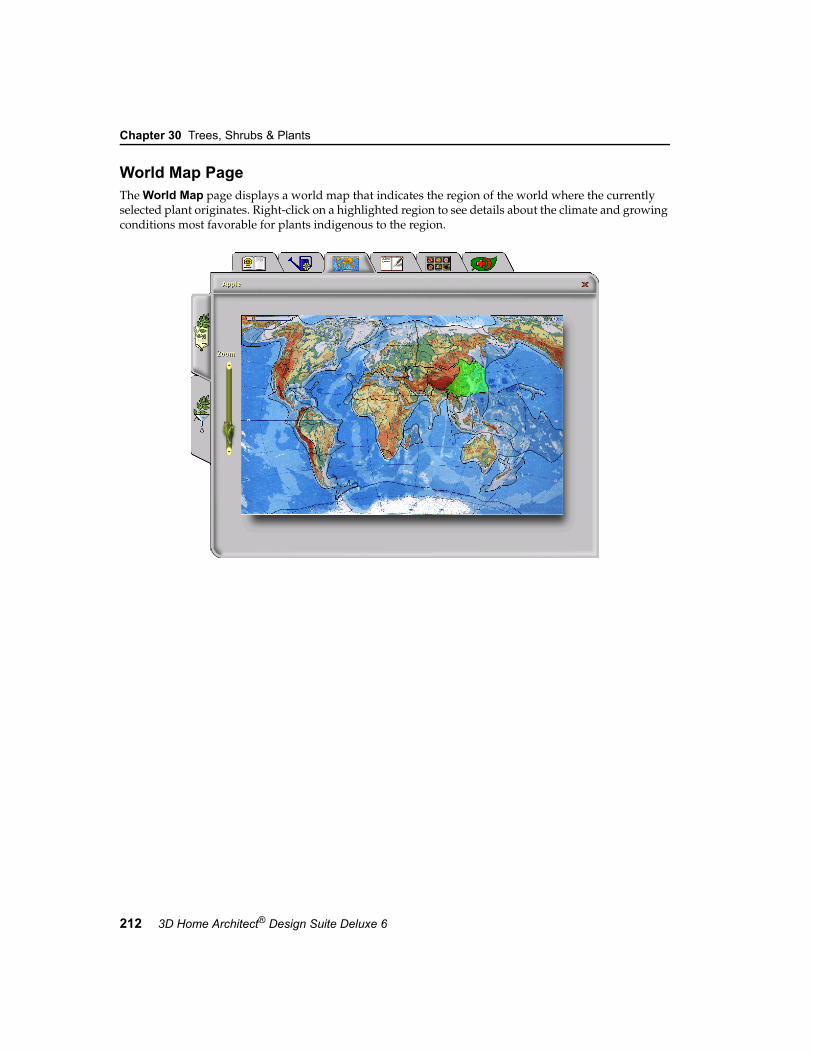
Chapter 30 Trees, Shrubs & Plants
212 3D Home Architect® Design Suite Deluxe 6
World Map PageThe World Map page displays a world map that indicates the region of the world where the currently selected plant originates. Right-click on a highlighted region to see details about the climate and growing conditions most favorable for plants indigenous to the region.

Notebook Page
User’s Guide 213
30
Notebook PageYou can use the Notebook page to enter and view notes about the currently selected plant. To select a plant, scroll through the list and click on it, or use the Search Edit field above the plant list to enter the first few letters of the plant name and find a quick match. Click in the box on the right side of the page and type your note. When you move to another page in the Encyclopedia, your text is saved automatically.

Chapter 30 Trees, Shrubs & Plants
214 3D Home Architect® Design Suite Deluxe 6
Picture PageThe Picture page contains a collage of thumbnail images of all the available plants in the plant list. You can browse through the images manually or by using the arrows at the top of the page.
To view a large picture of a selected plant, click the Full Size button at the top of the page.
Click the Thumbnails button to return to the thumbnails.

Diseases Page
User’s Guide 215
30
Diseases PageThe Diseases page lists the possible diseases that may affect a plant. By default, the disease list contains the diseases that can affect the currently selected plant. If you want to view a comprehensive list of diseases for all plants, click All in the bottom right corner of the page.
When you select a disease in the disease list, you will see a picture of the disease, details of its symptoms in the Symptoms windows, and care information in the Control window.
If you want to search in reverse to find all plants affected by a specific disease, click the Filter button at the bottom of the page. This opens the main Encyclopedia page. To restore your plant list, return to the Diseases page and click the All button.

Chapter 30 Trees, Shrubs & Plants
216 3D Home Architect® Design Suite Deluxe 6
Filtering the Plant ListThe Encyclopedia’s Plant Filter lets you filter out unwanted plants from your plant list by specifying various criteria.
To use the Plant Filter:1. Select the Plant Filter tab on the left side of
the Encyclopedia window.
2. Each Encyclopedia page has different filtering options. Click on the tabs along the top of the Encyclopedia window to select the page you want.
The main Encyclopedia page lets you select the Plant Type, Watering Needs, Lighting Preference, Soil Preference, Zone, Color (for flower, leaf, autumn leaf, and fruit), Height and Blooming Season.
The Plant Care Calendar page lets you select the Complexity of Care required, Speed of Growth (for both height and spread), Life Expectancy and Usage.
The World Map page lets you select the region of the world where the plants
originate. For example, if you wanted to find plants for an Asian-themed water garden, you would click on the Asian region of the map to exclude any plants that aren’t indigenous to Asia.
The Notebook page lets you filter plants by notes that you’ve entered previously on this page. For example, you could enter the note “Front Yard” for all plants that you want to use in your front yard. When you are ready to lay out the front yard of your landscape plan you can go back to the Plant Filter and limit your plant list to only the plants you’ve pre-chosen for your front yard.
The Picture page lets you limit your plant list by the part of the plant shown in its photo (leaf, bark, fruit, etc.).
The filter option available on the Diseases page is different, because it affects the disease list, not the plant list. To use this filter, click on the image that represents the part of the plant affected or type of infestation, then select the Encyclopedia tab on the left side of the window to switch to the regular Diseases page. For example, if you are considering planting lilies or daffodils in your garden, and want to know what type of diseases these bulb plants may encounter, click the Bulb image on the Diseases page (in Plant Filter mode), then go into Encyclopedia mode and select the Diseases page.
3. Select the filter criteria. Each icon and scale represents a specific plant criterion. As soon as you click on an icon or move a slider, filtering begins. To deselect an icon, click on it again.
Note: If some of the icons disappear, it is because no such plant is selectable within the current criteria. For example, if you select minimal water, the climber plant type icon will disappear because there are no climbing plants that will accept minimal watering.
If you select more than one icon within a single group, then all plants with any of the checked properties will be selected. For example, selecting maximum light and medium light will exclude all plants that
PlantFilterTab

Adding a Plant from the Encyclopedia to the Catalog
User’s Guide 217
30
flourish under minimal light (shade) conditions. If icons/sliders of more than one type are checked/moved, then plants that satisfy all the chosen criteria will be selected. For example, if you click on the deciduous tree icon in the Type box, the full sun icon in the Lighting Preference box, and the white square on the Color box, then only hardwood trees that flourish in full sunlight, require minimal watering, and produce white flowers will be selected.
4. The total number of plants available — based on the filters you have applied — is indicated on the leaf in the upper right corner of the window. If at any time you want to restore the complete list of plants, click Reset.
Adding a Plant from the Encyclopedia to the CatalogAlthough the catalog contains a vast array of plants for you to insert, it does not contain all the plants listed in the Plant Encyclopedia.
You can add any plant from the Plant Encyclopedia to any catalog by following the steps below.
To add a plant from the encyclopedia to the current catalog:1. Select File > Catalogs > Catalog Manager.2. In the Catalog Manager dialog, select Plants
from the Element drop box.
3. In the Select a Type window, select or create the group you want to add the plant to.
4. Select Catalog > Add Element.5. In the Plants dialog, select the Plant Info tab.
6. Click the Encyclopedia button to launch the Plant Encyclopedia.
7. On the Encyclopedia’s main page, select the desired plant in the plant list.
8. Click Select. Notice that the Plant Info page of the Plants dialog is now full with the selected plant’s information.
9. In the Name edit box, specify a name for your plant (disable Auto Name if you want to type in the name yourself).
10. Specify the remaining properties (Quantity or Behavior) if desired, then click OK in the Plants dialog. Note that the settings on the Appearance page have no effect on the plant’s appearance. The appearance of a plant is determined by settings in the Encyclopedia.
11. Click OK in the Catalog Manager dialog. The plant is added to your catalog.


219
Chapter
The 3D Home Architect® Design Suite catalog includes a great selection of exterior furniture so you can relax, eat and entertain outdoors. Furniture types include patio tables, patio chairs, picnic tables, loungers and benches.
All it takes is one click to insert any piece of furniture.
Exterior Furniture
Exterior Furniture

Chapter 31 Exterior Furniture
220 3D Home Architect® Design Suite Deluxe 6
Inserting Exterior FurnitureInserting exterior furniture is easy — just point and click.
To insert exterior furniture:1. Select Insert > Landscape > Exterior
Furniture, or click the Exterior Furniture button on the Landscape toolbar.
2. In the catalog, select the element you want to insert.
3. Position the element where you want it, then click to insert it.
4. Right-click and select Finish.
Moving Exterior FurnitureYou can move exterior furniture in plan view by simply clicking and dragging it.
To move exterior furniture:1. Select the element you want to move.
2. Hover your pointer over the element’s center grab handle to display the Move cursor.
3. Click and drag to move the element.
4. When the element is where you want it, release your mouse button.
Rotating Exterior FurnitureYou can rotate exterior furniture by clicking and dragging it.
To rotate exterior furniture:1. Select the element you want to rotate.
2. Hover your pointer over the triangular grab handle to display the Rotate cursor.
3. Click and drag to rotate the element.
4. When the element is at the desired rotation, release your mouse button.
Editing the Size of Exterior FurnitureYou can edit the height, width and depth of most exterior furniture.
To edit the size of exterior furniture:1. Select the element.
2. Right-click and select Properties, or select Edit > Modify Elements > Properties.
3. Edit the values on the Basic page. The Uniform Scale option ensures that the element scales uniformly when you change one of its dimensions.
4. Click OK.
Applying Different Colors or Finishes to Exterior FurnitureYou can use the Materials Paintbrush to quickly apply a color, fabric or finish to any exterior furnishing element.
To apply materials to exterior furniture:1. Display your model in 3D, and make sure the
furnishing element is visible in the view.
2. Select Edit > Materials Paintbrush, or click the Materials Paintbrush button on any tabbed toolbar.

Deleting Exterior Furniture
User’s Guide 221
31
3. In the catalog panel, select the color or material you want to apply. You can find an assortment of colors in the Paint category.
4. Click on the component you want to apply the material to. Materials are applied separately to the individual parts of the element. For example, you can apply a specific color to a tabletop, and a different color to the legs of the table.
5. When you are finished applying materials, right-click and select Finish.
Deleting Exterior FurnitureYou can delete any piece of exterior furniture in a couple of easy steps.
To delete exterior furniture:1. Select the element.
2. Press the Delete key on your keyboard, or right-click and select Delete, or select Edit > Modify Elements > Delete.


223
Chapter
3D Home Architect® Design Suite offers an excellent selection of exterior structures to make your outdoor living space more functional. These include play gyms, swings, sandboxes, trampolines, tennis and volleyball courts, detached garages, sheds, gazebos, arbors, garden boxes, greenhouses, pools and hot tubs.
If you are creating a landscape plan and do not have a model in your project, you can insert a house template to create your landscape plan around.
All structures are inserted with a single mouse click and can be easily moved, rotated and edited.
Exterior Structures
Exterior Structures

Chapter 32 Exterior Structures
224 3D Home Architect® Design Suite Deluxe 6
Inserting Exterior StructuresInserting exterior structures is easy — just point and click.
To insert an exterior structure:1. Select Insert > Landscape > Exterior
Structures, or click the Exterior Structures button on the Landscape toolbar.
2. In the catalog, select the structure you want to insert.
3. Position the structure where you want it, then click to insert it.
4. Right-click and select Finish.
A Note About House TemplatesA house template is basically the exterior shell of a finished home. If you are creating a landscape plan and your project does not contain a model, you can insert a house template to serve as the focal point of your plan.
Although a house template looks like a real house, it can’t be edited like a real model can. It is considered a single-click element, so clicking on any part of the template selects the entire house.
It is important to note that when you select the house template, the invisible bounding box is always square or rectangular, and does not necessarily follow the shape of the house outline.
This can interfere with the selection of other elements near the house. If you have inserted elements around the house, such as plants, and want to select them, you may want to use the View Filter to make the house template non-selectable for ease of editing your landscape plan.
Another thing to note is that the house template’s exterior walls are not visible in 2D. You only see the roof line. If you want to insert things like fills up against the exterior walls of the house, you will need to either draw them in 3D, or draw them in 2D and then move them into place in 3D.
Moving Exterior StructuresYou can move exterior structures in plan view by simply clicking and dragging them.
To move an exterior structure:1. Select the element you want to move.
2. Hover your pointer over the element’s center grab handle to display the Move cursor.
3. Click and drag to move the element.
4. When the element is where you want it, release your mouse button.
Rotating Exterior StructuresYou can rotate exterior structures by clicking and dragging them.
To rotate an exterior structure:1. Select the element you want to rotate.
2. Hover your pointer over the triangular grab handle to display the Rotate cursor.
3. Click and drag to rotate the element.
4. When the element is at the desired rotation, release your mouse button.
BoundingBox

Editing the Size of an Exterior Structure
User’s Guide 225
32
Editing the Size of an Exterior StructureYou can edit the height, width and depth of most exterior structures.
To edit the size of an exterior structure:1. Select the structure.
2. Right-click and select Properties, or select Edit > Modify Elements > Properties.
3. Edit the values on the Basic page. The Uniform Scale option ensures that the element scales uniformly when you change one of its dimensions.
4. Click OK.
Applying Different Colors or Materials to Exterior StructuresYou can change the look of an exterior structure by applying different colors or materials to it.
To apply different colors or materials to an exterior structure:1. Display your model in 3D, and make sure the
structure is visible in the view.
2. Select Edit > Materials Paintbrush, or click the Materials Paintbrush button on any tabbed toolbar.
3. In the catalog panel, select the color or material you want to apply.
4. Click on the component you want to apply the material to. Some structures can have different materials applied to individual parts. For example, the roof of a shed can be different from the shed’s walls.
5. When you are finished applying materials, right-click and select Finish.
Deleting an Exterior StructureYou can delete an exterior structure in a couple of easy steps.
To delete an exterior structure:1. Select the structure.
2. Press the Delete key on your keyboard, or right-click and select Delete, or select Edit > Modify Elements > Delete.


227
Chapter
Outdoor lighting can beautify any landscape and offers security and visibility at night. Lighting can also play an important part when you create exterior 3DTrueView™ renderings. 3D Home
Architect® Design Suite offers both light posts and path lights to enhance the exterior design of your home. You can even turn them on and off!
Outdoor lighting is inserted directly on the terrain. Just point and click!
Landscape Lighting
Landscape Lighting

Chapter 33 Landscape Lighting
228 3D Home Architect® Design Suite Deluxe 6
Inserting Landscape LightingInserting outdoor light posts and path lights is easy — just point and click.
To insert a landscape light fixture:1. Select Insert > Landscape >
Landscape Lighting, or click the Landscape Lighting button on the Landscape toolbar.
2. In the catalog, select the light you want to insert.
3. Position the light where you want it, then click to insert it.
4. Right-click and select Finish.
Moving a Landscape Light FixtureYou can move outdoor light fixtures in plan view by simply clicking and dragging them.
To move a landscape light fixture:1. Select the element you want to move.
2. Hover your pointer over the element’s center grab handle to display the Move cursor.
3. Click and drag to move the element.
4. When the element is where you want it, release your mouse button.
Editing the Size of a Landscape Light FixtureYou can edit the overall height, width and depth of light fixtures.
To edit the size of a landscape light fixture:1. Select the light fixture.
2. Right-click and select Properties, or select Edit > Modify Elements > Properties.
3. Edit the values on the Basic page. The Uniform Scale option ensures that the
element scales uniformly when you change one of its dimensions.
4. Click OK.
Editing a Light Fixture’s Light SourceA light source is usually a type of light bulb. You can edit a light fixture’s light source to achieve a different lighting effect.
To edit a light fixture’s light source:1. Select the light fixture whose properties you
want to edit.
2. Right-click and select Properties, or select Edit > Modify Elements > Properties.

Turning a Light On or Off
User’s Guide 229
33
3. Select the Lights tab.
4. To replace the currently selected light source with another type, click Edit, then select a light source from the Light Sources dialog. To add a light source to the fixture, click Add, then select a light source from the Light Sources dialog.
5. To delete a light source from the light fixture, click Delete.
6. To edit the position of the light source in relation to the light fixture, specify the X, Y and Z coordinates in the Light Position area. Coordinates are measured from the bottom center of the fixture. The small red box in the preview window indicates the current position of the light source. Changing the X value moves the light source left or right.
Selecting Middle positions the light in the center of the fixture, and selecting Minimum or Maximum positions it on the left or right side. If you select Custom you can enter a specific value in the adjacent edit box which is relative to the center position. For example, entering -3 moves the light source 3” left from the center. Changing the Y value moves the light source forward or backward. Selecting Minimum brings the light source all the way forward, and selecting Maximum moves it to the back of the fixture. Changing the Z value moves the light source up or down. Selecting Minimum positions the light source at the bottom of the fixture, while selecting Maximum positions it at the top of the fixture.
7. Once you’ve specified the properties, click OK.
Turning a Light On or OffBy default, lights are on when you insert them. You can virtually turn a light off by disabling its light source.
To turn a light on or off:1. Select the light fixture you want to turn on or
off.
2. Right-click and select Properties, or select Edit > Modify Elements > Properties.
3. Select the Lights tab.
eye icon

Chapter 33 Landscape Lighting
230 3D Home Architect® Design Suite Deluxe 6
4. To turn the light on or off, click the eye icon next to the light source name.
5. Click OK.
Changing the Look of a Landscape Light FixtureYou can use the Materials Paintbrush to apply different colors or materials to different parts of a light fixture.
To change the look of a light fixture:1. Display your model in 3D, and make sure the
light fixture is visible in the view.
2. Select Edit > Materials Paintbrush, or click the Materials Paintbrush button on any tabbed toolbar.
3. In the catalog panel, select the color or material you want to apply.
4. Click on the component you want to apply the material to. For some fixtures, materials are applied separately to the individual parts of the fixture.
5. When you are finished applying materials, right-click and select Finish.
Deleting a Landscape Light FixtureYou can delete an outdoor light fixture in a couple of easy steps.
To delete a light fixture:1. Select the light fixture.
2. Press the Delete key on your keyboard, or right-click and select Delete, or select Edit > Modify Elements > Delete.

231
Chapter
It’s always those small touches that really pull a design together. 3D Home Architect® Design Suite makes adding decorative accents and accessories a breeze - just point and click to insert a vast array of items, including fireplaces, fountains, wind chimes, decorative columns, corner accents, garden borders, weather vanes, door mats, patio umbrellas, trellises, bird baths, mailboxes, cars and planters.
Exterior Accessories
Exterior Accessories

Chapter 34 Exterior Accessories
232 3D Home Architect® Design Suite Deluxe 6
Inserting Exterior AccessoriesInserting exterior accessories is easy — just point and click. Accessories are inserted at a logical height, but you can edit their elevation after insertion if you want.
To insert an exterior accessory:1. Select Insert > Landscape > Exterior
Accessories, or click the Exterior Accessories button on the Landscape toolbar.
2. In the catalog, select the accessory you want to insert.
3. Position the element where you want it, then click to insert it.
4. Right-click and select Finish.
Moving Exterior AccessoriesYou can move exterior accessories in plan view by simply clicking and dragging them.
To move an exterior accessory:1. Select the element you want to move.
2. Hover your pointer over the element’s center grab handle to display the Move cursor.
3. Click and drag to move the element.
4. When the element is where you want it, release your mouse button.
Rotating Exterior AccessoriesYou can rotate exterior accessories by clicking and dragging them.
To rotate an exterior accessory:1. Select the element you want to rotate.
2. Hover your pointer over the triangular grab handle to display the Rotate cursor.
3. Click and drag to rotate the element.
4. When the element is at the desired rotation, release your mouse button.
Raising or Lowering an Exterior AccessoryYou can raise or lower an outdoor element using the Elevate tool.
To change the elevation of an exterior accessory:1. Select the element.
2. Right-click and select Elevate, or select Edit > Modify Elements > Elevate. The value in the Elevate dialog is the current elevation of the element.
3. In the Elevate dialog, specify the desired elevation of the bottom of the element above the ground.
4. Click OK.
Editing the Size of an Exterior AccessoryYou can edit the height, width and depth of most exterior accessories.
To edit the size of an exterior accessory:1. Select the element.
2. Right-click and select Properties, or select Edit > Modify Elements > Properties.
3. Edit the values on the Basic page. The Uniform Scale option ensures that the

Changing the Look of an Exterior Accessory
User’s Guide 233
34
element scales uniformly when you change one of its dimensions.
4. Click OK.
Changing the Look of an Exterior AccessoryYou can change the look of an exterior accessory by applying different colors or materials to it.
To apply different colors or materials to an exterior accessory:1. Display your model in 3D, and make sure the
accessory is visible in the view.
2. Select Edit > Materials Paintbrush, or click the Materials Paintbrush button on any tabbed toolbar.
3. In the catalog panel, select the color or material you want to apply.
4. Click on the component you want to apply the color or material to. Some accessories can have different materials applied to their individual parts.
5. When you are finished applying materials,
right-click and select Finish.
Deleting an Exterior AccessoryYou can delete an exterior accessory in a couple of easy steps.
To delete an exterior accessory:1. Select the element.
2. Press the Delete key on your keyboard, or right-click and select Delete, or select Edit > Modify Elements > Delete.


235
Chapter
You can insert pop-up sprinklers in your landscape plan with a single mouse click. When you insert a sprinkler, the coverage of the spray is outlined with a dashed line.
Irrigation
Irrigation

Chapter 35 Irrigation
236 3D Home Architect® Design Suite Deluxe 6
Inserting IrrigationThe catalog contains a wide selection of pop-up sprinklers with varying ranges of spray. You insert a sprinkler by simply pointing and clicking with your mouse. When you insert a sprinkler, the coverage of the spray is outlined with a dashed line.
To insert pop-up sprinklers:1. Select Insert > Landscape >
Irrigation, or click the Irrigation button on the Landscape toolbar.
2. In the catalog, select the sprinkler you want to insert.
3. Position the sprinkler where you want it, then click to insert it. You can continue inserting more sprinklers if you want.
4. Right-click and select Finish.
Moving SprinklersYou can move a sprinkler by simply clicking and dragging it.
To move a sprinkler:1. Select the sprinkler.
2. Hover your pointer over the sprinkler’s square grab handle to display the Move cursor.
3. Click and drag to move the element.
4. When the element is where you want it, release your mouse button.
Rotating SprinklersYou can rotate a sprinkler (and its spray) by simply clicking and dragging its rotation handle.
To rotate a sprinkler:1. Select the sprinkler.
2. Hover your pointer over the sprinkler’s triangular grab handle.
3. Click and drag to rotate the sprinkler, then release your mouse button.
Editing the Height of a SprinklerAll sprinklers in the catalog are 3” tall. You can edit the height of a sprinkler if you want.
To edit the height of a sprinkler:1. Select the sprinkler.
2. Right-click and select Properties, or select Edit > Modify Elements > Properties.
3. On the Basic page, edit the value in the Height edit box.
4. Click OK.
Editing a Sprinkler’s Spray CoverageYou can edit the distance covered by a sprinkler’s spray.
To edit a sprinkler’s spray properties:1. Select the sprinkler.
2. Right-click and select Properties, or select Edit > Modify Elements > Properties.
3. Edit the size values on the Basic property page. For most sprinklers you would edit the Width and Depth values. The Adjustable sprinkler in the catalog lets you specify a custom radius and included angle for the spray.
4. Click OK.
Deleting a SprinklerYou can delete a sprinkler in a couple of easy steps.
To delete a sprinkler:1. Select the sprinkler.
2. Press the Delete key on your keyboard, or right-click and select Delete, or select Edit > Modify Elements > Delete.

Drawing & Editing Tools
Part 9
Drawing Aids page 239
Measurement page 243
Commander page 247
Editing Your Design page 253


239
Chapter
3D Home Architect® Design Suite Deluxe offers a variety of powerful drawing tools that help you insert elements easily and precisely where you want them in your drawing.
If you want you can display a drawing grid in your drawing area, as well as set up a snap grid so that your cursor snaps to the grid when you are inserting elements. The Object Snap feature automatically snaps your pointer to existing objects, and the Angle Snap snaps your pointer to specified angles. The Collision Control feature prevents you from inserting elements where they do not fit.
You can set up drawing aids in your program settings, and toggle them on and off using the buttons on the Status bar.
Drawing Aids

Chapter 36 Drawing Aids
240 3D Home Architect® Design Suite Deluxe 6
Setting Up a Drawing GridA drawing grid is simply a set of horizontal and vertical lines that can help you orient objects to one another. By default, the spacing between grid lines is 1’, but you can change this if you want. Note that the drawing grid is a visual aid only, and will not be included in printouts.
To set up a drawing grid:1. Select Settings > Program Settings or
click the Program Settings button on the Settings toolbar.
2. In the Program Settings dialog, select the Drawing Aids tab.
3. In the Grid area, specify the desired distance between vertical grid lines in the X Spacing edit box.
4. Specify the desired distance between horizontal grid lines in the Y Spacing edit box.
5. By default, the grid is 150’ x 150’, which is the default size of the terrain. To change the overall size of the grid, enter the desired width in the X Limit edit box, and the desired height in the Y Limit edit box.
6. If you want to turn the grid on, check the Enable (F7) check box.
7. Click OK.
Turning the Drawing Grid On and OffYou can toggle the drawing grid on and off in one of two ways:
• Press F7 on your keyboard• Click the GRID button on the Status bar
Using the Grid SnapThe Grid Snap feature snaps your pointer to an invisible grid when inserting elements. By default, the spacing between the grid lines in the invisible grid is 1”, but you can change this if you
want. If you enable the Match Grid option, the invisible snap grid becomes the same size as the drawing grid. This will make it seem like you are snapping to the drawing grid while drawing.
To set up a snap grid:1. Select Settings > Program Settings or
click the Program Settings button on the Settings toolbar.
2. In the Program Settings dialog, select the Drawing Aids tab.
3. If you want the snap grid to be the same size as the drawing grid, check the Match Grid check box in the Grid Snap area.
4. To specify a custom distance between vertical grid lines, enter a value in the X Spacing edit box.
5. To specify a custom distance between horizontal grid lines, enter a value in the Y Spacing edit box.
6. If you want to turn the grid snap on, check the Enable (F4) check box.
7. Click OK.
Turning the Grid Snap On and OffYou can toggle the grid snap on and off in one of two ways:
• Press F4 on your keyboard• Click the GRIDSNAP button on the Status
bar
Using the Object SnapThe Object Snap feature makes elements that you are currently inserting automatically snap to existing elements in your drawing. For example, if you are drawing a wall and hover your pointer near an existing wall, your pointer will snap to the existing wall, making it easy to create a wall layout with cleanly intersecting walls.
You can set the pixel search distance for the object snap, which determines how close your pointer

Using Ortho
User’s Guide 241
36
needs to be to an element for it to snap to the element.
By default, the Object Snap is enabled, but you can turn it off whenever you want. There are three ways to turn the Object Snap on or off.
To turn the Object Snap on or off:• Press F5 on your keyboard• Click the OBJSNAP button on the Status bar
• Select Settings > Program Settings, then on the Drawing Aids page, check or uncheck the Enable (F5) check box in the Object Snap area
To set the pixel search distance:1. Select Settings > Program Settings or
click the Program Settings button on the Settings toolbar.
2. In the Program Settings dialog, select the Drawing Aids tab.
3. In the Object Snap area, type the desired number of pixels in the Pixel Search Distance edit box, or use the arrows to scroll up or down through a list of values.
4. Click OK.
Using OrthoThe Ortho feature restricts your cursor movement to 90-degree angles when you are inserting elements. This can be especially helpful when drawing elements like walls.
By default, Ortho is enabled. You can toggle it on and off using one of three methods.
To turn Ortho on or off:• Press F8 on your keyboard• Click the ORTHO button on the Status bar
• Select Settings > Program Settings, then on the Drawing Aids page, check or uncheck the Ortho (F8) check box
Using Angle SnapWhen the Angle Snap feature is turned on, your cursor snaps to specific angles when rotating an element. If you set your snap angle to 10º, for example, your cursor will snap at 10º intervals as you rotate the element.
By default, the Angle Snap is on. You can turn the Angle Snap on and off using one of three methods.
To turn the Angle Snap on or off:• Press F6 on your keyboard• Click the ANGLESNAP button on the Status
bar
• Select Settings > Program Settings, then on the Drawing Aids page, check or uncheck the Angle Snap (F6) check box
To change the snap angle:1. Select Settings > Program Settings or
click the Program Settings button on the Settings toolbar.
2. In the Program Settings dialog, select the Drawing Aids tab.
3. In the Ortho / Angle Snap area, type the desired snap angle in the Snap Angle edit box, or use the arrows to scroll up or down through a list of values.
4. Click OK.
Disabling/Enabling Collision ControlThe program’s intelligent Collision Control feature prevents objects from being inserted where they do not fit. By default, Collision Control is on, but you can turn it off whenever you like using one of three methods.
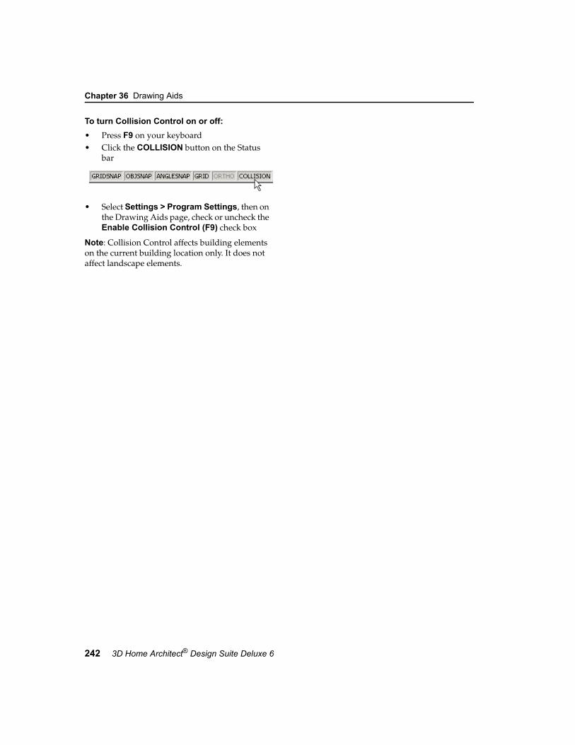
Chapter 36 Drawing Aids
242 3D Home Architect® Design Suite Deluxe 6
To turn Collision Control on or off:• Press F9 on your keyboard• Click the COLLISION button on the Status
bar
• Select Settings > Program Settings, then on the Drawing Aids page, check or uncheck the Enable Collision Control (F9) check box
Note: Collision Control affects building elements on the current building location only. It does not affect landscape elements.

243
Chapter
You can change the unit of measure used in a drawing, or select a different level of precision for your measurements.
Once you’ve drawn something, you can measure it using the Measure tool. You can also use the Area/Perimeter tool to instantly calculate the area of a room or building.
Measurement

Chapter 37 Measurement
244 3D Home Architect® Design Suite Deluxe 6
Changing the Unit of MeasureThe units of measure used in your project are determined by a template, which by default is either a feet/inches template or millimeters template.
Once you’ve opened a new project, you can change the units of measure and levels of precision used in that project by making selections on the Units of Measure page of the Program Settings dialog.
To set your units of measure:1. Select Settings > Program Settings or
click the Program Settings button on the Settings toolbar.
2. In the Program Settings dialog, select the Units of Measure tab.
3. Select either Imperial Units or Metric Units, then select the desired units to use.
4. Select a level of precision for each unit of measure. For example, selecting #’-# #/16” sets the level of precision to 1/16th of an inch when working in feet and inches.
5. Once you’ve set your units of measure, click OK.
Suppressing Metric Units in DialogsIf you have chosen to work in Metric units, you can choose to suppress units for length/distance, volume, and area measurements shown in dialogs. For example, 1200 mm would appear as simply 1200.
To suppress units:1. Select Settings > Program Settings or
click the Program Settings button on the Settings toolbar.
2. In the Program Settings dialog, select the Units of Measure tab.
3. With Metric Units selected, enable the Suppress metric units from dialogs check box.
4. Click OK.
Measuring DistancesUse the Measure tool to measure the distance between any two points in your 2D plan.
To use the Measure tool:1. Select Tools > Measure.
2. Click your first point on the screen.
3. Move your cursor in the direction you want to measure. A ruler is displayed that stretches as you move your cursor.
4. Click your second point on the screen. The distance is shown on the ruler as well as on the Status bar at the bottom of the screen.
5. Once you have measured your first distance, you can keep selecting points to measure
Measure Units Available
Imperial Feet-InchesInches
Metric MillimetersCentimetersMeters

Measuring Area and Perimeter
User’s Guide 245
37
additional distances from the last point selected. A running total is displayed on the Status bar.
6. When you have finished measuring, right-click and select Finish.
Measuring Area and PerimeterThe Area/Perimeter Calculator displays the area (e.g. square footage) and perimeter length of each location in your model. It also displays the total area and total perimeter (of all locations). You can use the calculator at any given point in time. The values in the calculator update automatically as your model increases or decreases in size.
Note the calculations are taken from the exterior side of the building’s walls.
To measure area:1. Select Tools > Calculate/Estimate > Area/
Perimeter.
2. To turn the grid lines off, uncheck the Show Grid check box.
3. To print the calculations, click Print.
4. When you are done viewing the area calculations, click OK.


247
Chapter
For very precise control when inserting or editing elements, 3D Home Architect® Design Suite Deluxe offers a helpful tool called the Commander, which lets you view or enter exact values for distance, direction and angles. It is especially handy for users with some CAD experience.
This chapter tells you how to turn the Commander on, and how to use it.
Commander

Chapter 38 Commander
248 3D Home Architect® Design Suite Deluxe 6
Displaying the CommanderThe Commander is a multi-functional tool that lets you enter precise values when inserting or editing elements. Even if you don’t need a high level of precision, you may want the Commander displayed so you can see lengths and angles as you draw or edit elements.
To display the Commander:
1. Select Settings > Program Settings or click the Program Settings button on the Settings toolbar.
2. In the Program Settings dialog, select the Workspace tab.
3. Check the Commander check box.
4. Click OK.
The Commander is displayed just below the drawing area, above the toolbar area. Initially the Commander will look grayed out because it is inactive. It will become active when you insert or edit elements.
Using the CommanderThe Commander can be a very useful tool when inserting or editing elements. Using the Commander you can:
• Specify the insertion height of an element before it is inserted
• Select a precise insertion point for an element• Specify a precise length and direction for
elements like walls and railings• Specify a precise distance and direction when
stretching or moving an element• Specify a precise angle when rotating an
element• Specify a precise radius/included angle
when curving a wall, deck or opening
Even if you don’t want to enter precise values, you can still use the Commander to view measurements as you draw and edit elements. The values in the Commander are linked to your cursor movement and update as you proceed through a command.
The Commander becomes instantly active when inserting elements. It is most useful for things like walls and railings, because it lets you enter a precise length for the element.
The Commander also becomes active when you are moving, stretching or rotating elements. If you have started moving, stretching or rotating an element using your mouse, the Commander displays the move distance or rotation angle as you move your mouse. If you want to be able the enter values in the Commander when moving, stretching or rotating an element, you need to first select an appropriate editing tool from the right-click menu or Edit > Modify Elements menu such as Move, Stretch, Lengthen, or Rotate.
Displaying the Coordinate IconThe Coordinate Icon marks the current point from which an action will be performed. In other words, it identifies the current reference point when using the Commander. By default, this icon is turned off. If you plan to use the Commander while working, you should turn on the Coordinate Icon.
To display the Coordinate Icon:1. Select Settings > Program Settings or
click the Program Settings button on the Settings toolbar.
2. In the Program Settings dialog, select the Drawing Aids tab.
3. In the Visual Aids area, check the Show Coordinate Icon check box.
4. Click OK.
Specifying the Insertion Height of an Element Before You Insert ItIf you have the Commander turned on, it will display a Base Height edit box as soon as an insertion tool becomes active.
The value shown in the Base Height edit box is the height at which the element will insert in your drawing. You can change the insertion height

Selecting a Reference Point When Inserting and Editing Elements
User’s Guide 249
38
before selecting an insertion point for the element by typing a value in the Base Height edit box and pressing ENTER. If the element is a building element, the height is measured from the floor level of the current building location to the element’s insertion point. If the element is a landscape element, the distance is measured from the terrain to the element’s insertion point. Most elements have their insertion point at the bottom of the element. Exceptions are windows and wall openings, in which the insertion point is located at the top of the element. In the case of windows and wall openings, the edit box reads “Head Height”.
Selecting a Reference Point When Inserting and Editing ElementsTo use the Commander, you must first specify a reference point, or base point, from which values can be measured. If you are drawing a wall, for example, the first point you click on the screen is considered the reference point. The Commander then becomes active, and you can enter a Distance and Direction (or X and Y values) for the wall.
If you want to use the Commander to edit an element (e.g. move or rotate it), you must select a point from which to measure the move distance/direction, or rotation angle. Most often you would select one of the element’s grab handles, which are the small blue squares that appear on the major points of an element when you select the element.
There are two ways to select a reference point once you’ve activated a tool:
• Click the point in your drawing.• Enter coordinates, or X, Y and Z values, in
the Commander. (See Defining Points in the Cartesian Coordinate System on page 250.)
Note that even if you choose to click the point in your drawing, you can see the coordinates of your cursor in the Commander as you move your mouse.
By default, coordinates are read from the last point selected in the drawing area. This point is marked by the Coordinate Icon (if enabled).
Entering Values in the CommanderThe Commander is intelligent and changes depending on the tool you are using. For example, if you are drawing walls, the Commander’s edit boxes become Distance, Direction, and Z. If you are curving walls, however, the edit boxes change to Radius and Included Angle.
You can move easily from one edit box to the next using your Tab key. Pressing ENTER after typing a value completes the current action.
When entering values in the Commander, especially when inserting or moving elements, it is important to be aware of the current coordinate system in the Commander.
The Commander offers two coordinate systems: Polar and Cartesian. The system you select determines how values are entered in the Commander when you are specifying points or distances.
Note that you can switch between the Polar and Cartesian coordinate system once you have selected a reference point to draw from or move from. You do this by making a selection from the coordinate system drop box on the left side of the Commander.
Note: If moving, stretching or rotating elements, and you want to enter values in the Commander, you need to first select an appropriate editing tool from the right-click menu or Edit > Modify Elements menu such as Move, Stretch, Lengthen or Rotate.

Chapter 38 Commander
250 3D Home Architect® Design Suite Deluxe 6
Direction and Angle of RotationDirection in a drawing is specified in degrees of an angle. The angle is calculated counterclockwise from the positive X axis.
The Four Primary Drawing Directions
Although the four primary drawing directions are the ones you will probably be working with the most, any angle is possible. If you disable Ortho and Angle Snap, and move an element randomly in your drawing area, there is no restriction on angles at all. Even if Ortho and Angle Snap are enabled, you can enter any angle you want in the Commander.
Defining Points in the Cartesian Coordinate SystemInitially when you start an insertion or editing command, the coordinate system is set to Cartesian. This lets you specify a precise reference point to draw or move from by entering X, Y and Z coordinate values in the Commander.
X. Enter an X coordinate to specify a horizontal (left/right) distance in 2D plan view.
Y. Enter a Y coordinate to specify a vertical (up/down) distance in 2D plan view.
Z. Enter a Z coordinate to indicate elevation, or height. If the element is a building element, the Z value is measured from the floor level of the current building location. If the element is a
landscape element, the Z value is measured from the terrain.
Remember that the coordinates are measured from the current reference point, which is marked by the Coordinate Icon. (See Entering Values in the Commander on page 249.)
In the Cartesian system, you can enter both positive and negative values for any of the coordinates.
Specifying Distance and Direction in the Polar Coordinate SystemThe Polar coordinate system becomes active once you have selected a reference point to draw from, or start a move from.
In the Polar coordinate system, you specify a distance and direction (angle) when drawing or moving an element.
Distance. Enter a positive value to specify the length of the element, or the move distance.
Direction. Enter the direction you want the element to run, or the direction in which you want to move an element. For information about how direction is specified, see Direction and Angle of Rotation on page 250.
Z. Enter the distance you want to move the element vertically. You can enter a positive or negative value to move the element up or down. If the element is a building element, the Z value is measured from the floor level of the current building location. If the element is a landscape element, the Z value is measured from the terrain.
Using the Commander When Rotating ElementsWhen you select the Rotate tool from the right-click menu or Edit > Modify Elements menu, then select a base point for the rotation, the Commander displays a Rotation Angle edit box.

Using the Commander When Curving Elements
User’s Guide 251
38
To specify the desired angle of rotation for the element, type the angle in the Rotation Angle edit box and press ENTER. For information on how angles are measured, see Direction and Angle of Rotation on page 250.
Using the Commander When Curving ElementsWhen curving an element such as a wall or floor opening, you can use the Commander to specify a precise curve angle.
Radius. The distance from the element (in its uncurved state) to the center point of the curve.
Included Angle. The angle formed between two radius lines extending from the center of the circle implied by the curve out to the endpoints of the arc. The larger the angle, the rounder and larger the curve.
It is not necessary to enter both the Radius and Included Angle values. If you enter one, the program automatically supplies the other. Also, if you enter a value and nothing happens after you press ENTER, then the value is not valid in relation to the dimensions of your element.
Rad
ius
IncludedAngle


253
Chapter
When you double-click after inserting an element or select Finish from the right-click menu, you automatically go into Selection Mode, meaning you can select elements in your drawing area and edit them.
Most elements can be moved, rotated, copied and deleted. Some elements have additional editing commands available. For example, you can lengthen, break and curve walls. All elements have a property sheet where you can change the size or appearance of the element.
To access a menu of editing commands for a selected element, just right-click in the drawing area or select Edit > Modify Elements. Certain functions can be performed without selecting any commands at all. For example, you can move and rotate most elements by simply clicking and dragging your mouse.
This chapter describes how to select elements, and use general editing commands like Move, Rotate, Elevate, Duplicate and Delete. It also describes how to access and edit element properties. For information about editing a specific type of element, see the chapter about that element.
Editing Your Design

Chapter 39 Editing Your Design
254 3D Home Architect® Design Suite Deluxe 6
Undoing the Previous ActionThe Undo tool cancels your most recent action. You can undo as many actions as you have taken since your last save.
To undo an action:• Select Edit > Undo, or• Click the Undo button on the Standard
toolbar, or• Press Ctrl+Z
Tip: You can use the Redo tool to reapply an action you have canceled using the Undo tool.
Redoing an UndoThe Redo tool reapplies a tool that you have reversed using Undo. Redo will only work directly following an Undo.
To redo a task:• Select Edit > Redo, or• Click the Redo button on the Standard
toolbar, or• Press Ctrl+Y
Accessing Edit CommandsWhen you have an element selected, you can access a menu of edit commands by right-clicking in the drawing area, or by selecting Edit > Modify Elements.
Menus vary depending on the element selected. Typical commands are Properties, Move, Rotate, Duplicate, and Delete. If two types of elements are selected (such as a floor and a wall), only commands that are common to both element types are available.
Certain functions can be performed without selecting any commands at all. For example, you can move and rotate most elements by simply clicking and dragging your mouse.
Moving ElementsWhen you select an element, you are automatically in Drag and Drop mode. If the element is a singular, one-click object, like a
cabinet or plant, you can move the element by simply clicking and dragging it. If you want to move an area-drawn element, such as a roof, you need to select the Move Whole Element tool before clicking and dragging Otherwise, doing a straight drag-and-drop will only stretch it. If you click and drag a wall, all walls attached to it move with it.
If you have your Commander turned on and would like to be able to enter precise values for the move, you need to select the Move tool instead of doing a straight drag-and-drop.
Note: Elements associated with walls, such as doors and windows, can only be moved within the wall they are in. You cannot move them to another wall.
Doing a Straight Drag-and-DropThe straight drag-and-drop method is ideal for singular, one-click elements like cabinets and plants.
To move an element using drag-and-drop:1. Select the element you want to move. You are
now in Drag and Drop mode.
2. Hover your pointer over the element’s center grab handle to display the Move cursor.
3. Click and drag to move the element.
4. When the element is where you want it, release the mouse button.
Using the Move ToolUse the Move tool when you want to be able to specify a precise distance and direction for the move in the Commander.
To move an element using the Move tool:1. Select the element you want to move.
2. Right-click and select Move, or select Edit > Modify Elements > Move.
3. Select a base point for the move. The move distance and direction will be measured from this point.

Raising or Lowering an Element
User’s Guide 255
39
4. Without holding your mouse button down, move your mouse to move the element. Select the point you want to move the element to, or enter a distance and direction in the Commander.
Raising or Lowering an ElementMost elements can be raised or lowered using the Elevate tool on the element’s right-click menu. Some elements, such as roofs, do not provide access to the Elevate tool. In the case of a roof, you can raise or lower it by changing the Support Height variable in its properties.
Many block elements (like furniture and plants) also have a Distance above current location or terrain variable in their properties that you can use to raise or lower the element. Walls have an Extension Below Base variable, and columns have a Base Offset variable in their properties that you can edit.
To raise or lower an element using the Elevate tool:1. Select the element you want to raise or lower.
2. Right-click and select Elevate, or select Edit > Modify Elements > Elevate. The value shown in the Elevate dialog is the current elevation of the element.
3. In the Elevate dialog, specify the desired elevation of the element above the floor. If the element is a landscaping element, the value you specify is relative to the terrain. The distance you enter is the distance from the floor or terrain to the insertion point of the element. For most elements, the insertion point is at the base of the element. For windows and wall openings, however, the insertion point is at the top of the element. Therefore, if you are raising or lowering a window or wall opening, specify the desired distance from the floor to the top of the window or opening.
4. Click OK.
To raise or lower a block element by editing its properties:1. Select the element you want to raise or lower.
2. Right-click and select Properties, or select Edit > Modify Elements > Properties.
3. In the properties dialog, select the Behavior tab. If there is no Behavior tab, you will need to use the Elevate tool to raise or lower the element.
4. Edit the value in the Distance above current location or terrain edit box.
5. Click OK.
Rotating Elements in 2D Plan ViewSingular, one-click elements like cabinets and furniture can be rotated on the spot by simply clicking and dragging them while in Rotation mode.
Railings can be rotated by clicking and dragging their end points.
For most other elements such as walls, floors, ceilings or roofs, you need to use the Rotate tool. You also need to use the Rotate tool if you want to be able to enter a precise rotation angle in the Commander, or you want to rotate the element about a point other than the center point of the element.
Doing a Simple, On-the-Spot RotationIf you see a triangular grab handle on an element when it is selected, it can be rotated by simply clicking and dragging it. Using this method, the element is rotated about its center point.
If your Angle Snap is on, the element will rotate in increments of whatever angle is set for the
Rotation handle
.Center . . .90° 180° 270°

Chapter 39 Editing Your Design
256 3D Home Architect® Design Suite Deluxe 6
Angle Snap. If the Angle Snap is off, the element will rotate in increments of 1º.
To rotate an element by clicking and dragging:1. Select the element you want to rotate.
2. Hover your pointer over the triangular grab handle to display the Rotate cursor. If you do not see the triangular grab handle, the element can only be rotated with the Rotate tool.
Tip: If the square grab handle is in close proximity to the triangular grab handle, you may want to zoom in on the element to distinguish between the two grab handles.
3. Click and drag to rotate the element.
4. When the element is at the desired rotation, release your mouse button.
Using the Rotate ToolUsing the Rotate tool you can rotate an element about any selected base point. You should also use the Rotate tool if you want to be able to enter a precise rotation angle in the Commander.
If your Angle Snap is on, the element will rotate in increments of whatever angle is set for the Angle Snap. If you are using the Commander, you can override the Angle Snap by entering the desired angle in the Commander. If the Angle Snap is off, the element will rotate in increments of 1º.
To rotate an element using the Rotate tool:1. Select the element to rotate.
2. Right-click and select Rotate, or select Edit > Modify Elements > Rotate.
3. Select a base point for the rotation. The base point can be any point on the element (e.g. center point or corner point), or any point in the drawing area. The point you pick establishes an automatic baseline that runs
through the point at 180°. You can rotate full-circle around this baseline.
Tip: If you want to align an element with another element that may be lying at an odd angle, select a base point on the other ele-ment, then line up your rotation line with that element.
4. Without holding your mouse button down, move your mouse to rotate the element. The element will rotate from the defined base point in the direction you move the mouse. If the Commander is turned on, you can view the angle of rotation as you rotate, or enter a precise angle. Positive angle values are read in a counter-clockwise direction, while negative values are read in a clockwise direction.
Changing an Element’s OrientationSymbol elements, such as furniture and light fixtures, are oriented in a logical fashion when you insert them in your drawing. For example, tables are inserted in a flat, upright position on the floor, and electrical outlets are inserted in a vertical position on the face of walls. You can edit the orientation of most symbol elements. For example, you may want to flip an air register so that you can insert it on the ceiling in your basement.
To change an element’s orientation:1. Select the element.
2. Right-click and select Properties, or select Edit > Modify Elements > Properties.
Base Point
.Baseline
270° rotation
.

Copying Elements on the Same Location
User’s Guide 257
39
3. On the Basic property page, click the appropriate arrow keys in the Orientation area to rotate the element.
(Y, Z) axes: Rotates the element front to back, and vice versa.
(X, Z) axes: Rotates the element towards its left or right side in 3D.
(X, Y) axes: Rotates the element left or right in 2D plan view.
Copying Elements on the Same LocationThe Duplicate tool creates a copy of a selected element that you can then position where you like on the current location.
To duplicate an element:1. Select the element to copy.
2. Right-click and select Duplicate, or select Edit > Modify Elements > Duplicate.
3. Select a base point for the copy movement. Typically you would select one of the element's grab handles, but you can click anywhere in the drawing. The base point is simply a reference point used to define the move distance.
4. Select the point you are copying the element to. You can do this by moving your mouse and then clicking to insert the copy, or by typing a distance and direction in the Commander.
Copying Elements to Other LocationsThe Duplicate to Locations tool lets you copy existing elements to other locations. This is useful if the elements you have already drawn will have the same layout on another location. For example, you can copy the exterior walls on the Ground Floor to the Second Floor and instantly create another story.
To copy elements to other locations:1. Make sure the location you want to copy
elements FROM is current.
2. Select the elements you want to copy.
3. Right-click and select Duplicate to Locations.
4. Select the target location(s) you want to copy the elements to.
5. Click OK.
Note: The location you are copying to must exist in the Building Locations dialog. For more information see Defining Building Locations on page 18.
Arraying ElementsWhen you array elements, you create multiple copies of an element at the same time. You can create an array in a single row or column, or a layout of rows and columns. You can also control the spacing between elements in the array, and the array's rotation angle.
Sample array of posts
To array an element:1. Select the element you want to array.
2. Right-click and select Array, or select Edit > Modify Elements > Array.
Rows
Columns

Chapter 39 Editing Your Design
258 3D Home Architect® Design Suite Deluxe 6
3. In the Number of Rows box, type the number of horizontal rows you want or use the arrows to select a value.
4. In the Number of Columns box, type the number of vertical columns you want.
5. In the Distance Between Rows box, type the spacing you want between rows. This determines the distance between elements appearing in columns (vertical spacing).
6. In the Distance Between Columns box, type the spacing you want between columns. This determines the distance between elements appearing in rows (horizontal spacing).
Note: If you are working in Imperial, make sure you include the feet symbol (e.g. 4’) if the value is in feet. Otherwise, the value is taken as inches.
7. In the Array Rotation Angle box, type the degree of rotation for the array.
8. Click OK. The array is created.
Note: The Array tool is only available for certain elements.
Deleting ElementsYou can delete an element from your drawing in two quick steps.
To delete an element:1. Select the element.
2. Press the Delete key on your keyboard, or right-click and select Delete, or select Edit > Modify Elements > Delete.
Editing the Size and Composition of an ElementYou can edit the physical make-up of an element as well as its dimensions by accessing the element’s Basic property page. Some elements have additional property pages that control its composition. For example, cabinets have Leaf and Details property pages.
When you edit the properties of elements that exist in your drawing, only selected elements are changed. Other occurrences of the element in your drawing remain unchanged. You can, however, select and edit multiple elements at the same time provided they share the same properties.
To edit the properties of an inserted element:1. Select the element you want to edit. To select
multiple elements, use Shift + click.
2. Right-click and select Properties, or select Edit > Modify Elements > Properties.
3. Adjust the properties as desired. Clicking a dimension marked with an alphabetical character (a, b, c, etc.) highlights the corresponding dimension in the element graphic, and vice versa, if one exists.
4. Click OK. The selected elements are updated in the drawing.

Changing an Element’s Material or Color
User’s Guide 259
39
Note: Editing the properties of an element in your drawing has no effect on the element’s property definition in the catalog it came from. If you want to edit an element in a catalog, see Adding and Editing Elements in a Catalog on page 335. Editing an element in a catalog affects all future insertions of that element in your drawing.
Changing an Element’s Material or ColorWhen you view your design in Rendered or Patterned mode, elements are displayed using materials that are defined in the elements’ properties. A material can be a texture, such as brick, or a color. Materials also have a pattern assigned to them, which is what you see when you view in Patterned view. You can select a different material for each of an element’s components.
Note: You can’t change the way an element looks in 2D plan view.
There are two ways to change an element’s material settings: using the Materials Paintbrush, or through the element’s Appearance property page.
The Materials Paintbrush is best used in 3D view. It lets you select a material or color in the catalog, then apply it to parts of an element. For example, if you want your table legs to be blue, you can select the Blue Paint material, then click on of the table’s legs. All table legs will update automatically. When you use the Materials Paintbrush on an element, the settings on the element’s Appearance property page update to match the selections you made with the Materials Paintbrush.
If you choose to edit an element’s material through its Appearance property page, you can select different materials for each of the element’s parts, rather than just a selected part. It doesn’t matter if you’re in a 2D view or 3D view.
To use the Materials Paintbrush:1. Select Edit > Materials Paintbrush, or
click the Materials Paintbrush button on any tabbed toolbar.
2. In the catalog panel, select the material you want to apply. There is an incredible selection to choose from, including Wood, Brick, Marble, Concrete, Steel, Carpet, Tile, Roofing and Fabric. If you want to apply a solid color select something from the Paint category.
3. In 3D view, click on the element part that you want to apply the material to. The material is immediately applied.
4. Right-click and select Finish.
To change an element’s material through the Appearance property page:1. Select the element you want to edit. To select
multiple elements, use Shift + click.
2. Right-click and select Properties, or select Edit > Modify Elements > Properties.
3. Select the Appearance tab.

Chapter 39 Editing Your Design
260 3D Home Architect® Design Suite Deluxe 6
4. In the Components pane, select the component whose material you want to change.
5. In the Material area, click the Select button.
6. In the Materials dialog, select the group containing the desired material. If you want to choose a solid color, select the Paint group.
7. Select the material you want to use. The swatches in the preview windows update automatically. If you want to edit the material, click on one of the swatches to access the Edit Materials dialog. For information about editing materials, see Editing Material Properties on page 349.
8. Click OK to return to the Appearance page.
9. If you want to rotate the material on the element, enter an angle in the Rotation edit box, or use the arrows to scroll through a list of angles. This rotates the material in a clockwise direction.
10. To shift the material on the element (left, right, up or down), use the Position arrows.
11. Select another component in the Components pane and select a material for that component.
12. When all your materials are defined, click OK.
Note: When you edit the material of an element in your drawing, the element’s material definition in the catalog does not change. The change only applies to the selected element. If you want to change the element’s properties in the catalog, see Adding and Editing Elements in a Catalog on page 335.

Power ToolsPart 10
Project Trace Image page 263
Photo Boards page 267
Text & Dimensions page 273
Project Estimate page 285
3DTrueView™ page 289


263
Chapter
Using the Project Trace Image tool you can import a BMP, JPG or TGA file into your drawing space. You can then trace the image using elements from the catalog, creating a true 3D Home
Architect® Design Suite model. This is the perfect tool to use if you have sketched out ideas in a drawing program or scanned a floor plan that you have permission to use, and want to recreate the plan in 3D Home Architect® Design Suite.
You can resize the image if you need to before tracing, and delete it once you’re done tracing.
Most floor plans are copyrighted, so make sure you have permission to copy them.
Project Trace Image

Chapter 40 Project Trace Image
264 3D Home Architect® Design Suite Deluxe 6
Importing an Image to TraceYou can import a BMP, JPG or TGA image, such as a scanned floor plan, and trace it using elements from the catalog, creating a true 3D Home Architect® Design Suite model.
To import an image to trace:1. In 2D plan view, select File > Import >
Project Trace Image.
2. In the Open dialog, select the file type you are importing from the File type drop box. You can import BMP, JPG or TGA files.
3. Locate the file to import, then click Open.
4. If you want to reverse the image (i.e. flip it left to right), enable the Flip Horizontal check box. If you want to flip the image vertically (so it is upside down), enable the Flip Vertical check box.
5. To change the scale of the image, enter the dimensions in the Length and Height edit boxes. Typically you would use the overall dimensions shown on the floor plan. For example, if the house is 70’ long, enter 70’ in the Length edit box. Keeping the Maintain Aspect Ratio check box enabled ensures that the image scales uniformly when one of the dimensions is changed. This prevents the image from becoming distorted.
6. Click OK. A bounding box is attached to your cursor.
7. Position the box in your drawing area, then click to insert it. The image is displayed.
Matching the Floor Plan’s Drawing ScaleIf the floor plan is not the right size, you can scale it up or down to match the plan’s drawing scale. Having a correct drawing scale is important for tracing purposes so elements can be created at the correct size.
To resize a project trace image:1. Select the trace image.
2. Right-click and select Resize Image, or select Edit > Modify Elements > Resize Image.
3. Find a wall with a known length, then select a point at each end of the wall.
4. In the Resize Image dialog, enter the distance between the two points as shown on the floor plan, then click OK. The image is scaled instantly.
Tracing the Imported Floor PlanTracing an imported image is easy — just use the Insert tools described earlier in this User’s Guide.
• To trace foundation walls, see Creating a Basement or Crawlspace Foundation on page 44.
• To trace ground floor exterior walls, see Drawing the Ground Floor Exterior Walls on page 54.
• To trace interior walls, see Drawing Interior Walls on page 57.
• To insert doors, see Inserting Doors on page 62.
• To insert windows, see Inserting Windows on page 66.
• To insert wall openings, see Inserting Wall Openings on page 70.
• To insert stairs, see Inserting Stairs and Ramps on page 82.

Deleting a Project Trace Image
User’s Guide 265
40
• To insert cabinets, appliances and other elements, see chapters 14-20.
• To insert plants, see Inserting Plants on page 204.
Deleting a Project Trace ImageOnce you’re done tracing a floor plan, you can delete the trace image from your drawing, leaving just your 3D Home Architect® Design Suite model on the screen.
To delete a project trace image:1. Select the trace image.
2. Press the Delete key on your keyboard, or right-click and select Delete, or select Edit > Modify Elements > Delete.
Note: If you prefer you can just hide the project trace image from view instead of deleting it. See Displaying/Hiding Project Trace Images on page 37.


267
Chapter
3D Home Architect® Design Suite lets you import digital photographs or scanned images into your work space. The image is oriented vertically in 3D view, much like a billboard. You could, for example, import a picture of your backyard, so when you look out the window, it feels like you’re home.
A photo board can be stationary or set to rotate with the camera so it’s always facing you. You can also control the height and width of the photo board.
The handy Photo Board Wizard steps you through the process quickly and easily.
Photo Boards

Chapter 41 Photo Boards
268 3D Home Architect® Design Suite Deluxe 6
Importing a Photo BoardA photo board is simply a digital image that is oriented vertically in your 3D workspace. You can import any image you want — your family, pets, neighbor’s house — the only limit is your imagination. The handy Photo Board Wizard does it all in a few quick steps.
To import a photo board:1. Select File > Import > Photo Board Wizard.
2. Click Next.
3. Type a name for your photo board.
4. Click the Select button, then select the image you want to import. You can import BMP, JPG and TGA files. The image is displayed in the preview window.
5. Define the size of the image by entering values in the Height and Width edit boxes. Generally you should specify a size that is as close to reality as possible. For example, if the image is of a person who is six feet tall, you should enter a value close to 6’ in the Height edit box.
6. Click Next.
7. Specify whether you want the photo board to be stationary or active. If Stationary is selected, the board will always remain oriented the same way, regardless of changes in your camera angle. If Billboard is selected, the photo board will rotate toward the camera so it will always face you in 3D.

Adding an Imported Photo Board to Your Catalog
User’s Guide 269
41
8. Click Next.
9. Click Finish. The photo board is attached to your cursor, ready to be inserted.
10. Position the photo board where you want it, then click to insert it.
11. Right-click and select Finish.
Adding an Imported Photo Board to Your CatalogYou can save a photo board that you have imported using the Photo Board Wizard to your catalog so you can insert it again in any project.
To save your photo board to the current catalog:1. Select File > Catalogs > Save
Element to Catalog. Your pointer changes to a catalog cursor.
2. Click on the photo board in your drawing.
3. Click Yes to save the photo board. The photo board is added to the current catalog.
Inserting a Photo Board from the CatalogThe catalog contains a collection of photo boards containing pictures of animals. If you have saved your imported photo board to the catalog, it is also displayed with the existing photo boards in the catalog.
To insert a photo board from the catalog:1. Select Insert > Photo Board.
2. In the catalog panel, select the photo board you want to insert.
3. Position the photo board where you want it, then click to insert it.
4. Right-click and select Finish.
Moving a Photo BoardYou can move a photo board easily by just clicking and dragging it.
To move a photo board:1. Select the photo board.
2. Hover your pointer over the board to display the Move cursor.
3. Click and drag to move the board.
4. When the board is where you want it, release your mouse button.
Rotating a Photo Board in 2D Plan ViewYou can use the Rotate tool to rotate a photo board about a selected point in 2D plan view.
To rotate a photo board:1. Select the photo board.
2. Right-click and select Rotate, or select Edit > Modify Elements > Rotate.
3. Hover your pointer over the point you want to rotate the photo board around.
4. Click and drag to rotate the photo board, then release your mouse button.

Chapter 41 Photo Boards
270 3D Home Architect® Design Suite Deluxe 6
Changing the Elevation of a Photo BoardYou can raise or lower a photo board using the Elevate tool on the right-click menu.
To raise or lower a photo board:1. Select the photo board.
2. Right-click and select Elevate, or select Edit > Modify Elements > Elevate. The value shown in the Elevate dialog is the current elevation of the photo board.
3. In the Elevate dialog, specify the desired elevation of the photo board above the terrain.
4. Click OK.
Tip: You can also change a photo board’s elevation by changing the Distance above current location or terrain variable on the photo board’s Behavior property page.
Changing a Photo Board from Stationary to Rotating and Vice VersaYou can choose whether a photo board is stationary or rotating after it has been inserted. A stationary board keeps the same orientation regardless of changes in the camera angle. A rotating board always rotates towards the camera.
To change a photo board’s type:1. Select the photo board.
2. Right-click and select Properties, or select Edit > Modify Elements > Properties.
3. In the Type area, click Stationary for a stationary photo board, or Billboard for a rotating photo board.
4. Click OK.
Editing the Size of a Photo BoardYou can edit the height and width of a photo board after it has been inserted.
To edit the size of a photo board:1. Select the photo board.
2. Right-click and select Properties, or select Edit > Modify Elements > Properties.
3. Edit the Height or Width in the Properties area. If Maintain Aspect Ratio is checked, the height will automatically change if you edit the width, and vice versa. This ensures the image doesn’t get distorted.
4. Click OK.
Deleting a Photo BoardYou can delete a photo board in a couple of easy steps.
To delete a photo board:1. Select the photo board.
2. Press the Delete key on your keyboard, right-click and select Delete, or select Edit > Modify Elements > Delete.
Creating Transparency in Photo Board ImagesYou may find that you want to make portions of your photo board image transparent for a more realistic effect. If the image is of a person, for example, you may want to make the background in the image transparent so that when you insert the photo board in your drawing, you see just the person in your 3D view.
To create transparency in your photo board image, you need to use a graphic editing program such as Microsoft® Paint to apply a magenta color to those portions you want to make transparent.
The RGB color settings for magenta are as follows:
Red: 255 Green: 0 Blue: 255
Magentabackground

Creating Transparency in Photo Board Images
User’s Guide 271
41
Once you have finished editing the image in the graphic editing program, you can re-import the image into 3D Home Architect® Design Suite using the Photo Board Wizard.
Photo board with no transparency
Photo board with transparency


273
Chapter
Using text tools you can add text to any area of your drawing. You may want to add a title to the plan, or label rooms or specific elements. You can use whatever fonts and colors you want.
Dimensions are used to convey precise measurements. You can dimension the exterior of your design instantly, and quickly insert interior dimensions with a few simple mouse clicks.
This chapter describes all text and dimension tools.
Text & Dimensions

Chapter 42 Text & Dimensions
274 3D Home Architect® Design Suite Deluxe 6
Adding Text to Your DrawingYou can add text of varying size, color and font to your drawings. Text can be moved and rotated after it has been inserted, just like most other elements.
To add text to your drawing:1. Select Tools > Text > Add Text, or
click the Add Text button on the Notation toolbar.
2. In the Text dialog, type the text you want to add. If you want to import a text (*.txt) file, click Import, then select the file to import.
3. To select a style for the text, click the Text Style button and select or create a text style in the Text Styles dialog.
4. By default, text is left justified. For multi-line text, this means that text lines will line up on the left, and be ragged on the right. If you want to change the justification of the text, click the appropriate button in the bottom left corner of the dialog.
5. If you want to automatically return to the Text dialog after you have inserted the current text, enable the Multiple text insert check box. This is ideal when you want to insert different pieces of text in your drawing without having to select the Add Text tool again.
6. Click OK. The text is attached to your cursor.
7. Position the text where you want it, then click to insert it.
Moving TextYou can move text by simply clicking and dragging it.
To move text:1. Select the text you want to move.
2. Position your pointer over the blue grab handle to display the Move cursor.
3. Click and drag to move the text, then release your mouse button.
Rotating TextYou can change the angle of text using the Rotate tool.
To rotate text:1. Select the text you want to rotate.
2. Right-click and select Rotate, or select Edit > Modify Elements > Rotate.
3. Hover your pointer over the point you want to rotate around — typically the blue grab handle.
4. Move your mouse to rotate the text in the desired direction.
5. When the text is at the desired rotation, click to set the position.
Editing Text ContentYou can edit the content of a text element by accessing its properties.
To edit text:1. Select the text you want to edit.
2. Right-click and select Properties, or select Edit > Modify Elements > Properties.
3. In the Text dialog, edit the text in the text window.
4. Click OK.
Left Justified Right Justified
Centered

Changing the Style of Text
User’s Guide 275
42
Changing the Style of TextText style settings include font, font style, size, and color. You can select a different text style for selected text, or edit individual text style properties.
To change the style of text:1. Select the text whose style you want to
change.
2. Right-click and select Properties, or select Edit > Modify Elements > Properties.
3. In the Text dialog, click Text Style.
4. In the Text Styles dialog, select a new text style, or edit the individual properties of the current text style.
You can also create a new text style by clicking the Add Item button.
Font. A set of text characters in a specific style and size.
Font Style. The style of text. Choices can include Regular, Italic, Bold, and Bold Italic.
Text Height. The size of text.
Text Color. The color of text. Click the swatch to access the Color dialog and select a color.
5. Click OK in the Text Styles dialog.
6. Click OK in the Text dialog. The text is changed automatically.
Note: Text styles that are edited or added through inserted text are saved with the current project only. If you want to save them in the text styles library file, so that they can be made available in other projects, see Saving Customized Text Styles to the Text Styles Library File on page 363.
Changing the Justification of Multi-line TextYou can change the way multiple lines of text are aligned.
To change the justification of text:1. Select the text you want to edit.
2. Right-click and select Properties, or select Edit > Modify Elements > Properties.
3. In the Text dialog, click the appropriate justification button below the editing window.
4. Click OK.
Deleting TextYou can delete selected text from your drawing in a couple of easy steps.
To delete text:1. Select the text you want to remove. You can
select multiple entries using Shift+click.
2. Press the Delete key on your keyboard, or right-click and select Delete, or select Edit > Modify Elements > Delete.
Adding Text with a LeaderYou can insert text with an arrow attached to it that points to a particular element or area in your drawing. The leader has two segments and can be oriented in any fashion.
Left Justified Right Justified
Centered
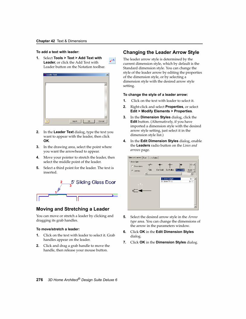
Chapter 42 Text & Dimensions
276 3D Home Architect® Design Suite Deluxe 6
To add a text with leader:1. Select Tools > Text > Add Text with
Leader, or click the Add Text with Leader button on the Notation toolbar.
2. In the Leader Text dialog, type the text you want to appear with the leader, then click OK.
3. In the drawing area, select the point where you want the arrowhead to appear.
4. Move your pointer to stretch the leader, then select the middle point of the leader.
5. Select a third point for the leader. The text is inserted.
Moving and Stretching a LeaderYou can move or stretch a leader by clicking and dragging its grab handles.
To move/stretch a leader:1. Click on the text with leader to select it. Grab
handles appear on the leader.
2. Click and drag a grab handle to move the handle, then release your mouse button.
Changing the Leader Arrow StyleThe leader arrow style is determined by the current dimension style, which by default is the Standard dimension style. You can change the style of the leader arrow by editing the properties of the dimension style, or by selecting a dimension style with the desired arrow style setting.
To change the style of a leader arrow:1. Click on the text with leader to select it.
2. Right-click and select Properties, or select Edit > Modify Elements > Properties.
3. In the Dimension Styles dialog, click the Edit button. (Alternatively, if you have imported a dimension style with the desired arrow style setting, just select it in the dimension style list.)
4. In the Edit Dimension Styles dialog, enable the Leaders radio button on the Lines and arrows page.
5. Select the desired arrow style in the Arrow type area. You can change the dimensions of the arrow in the parameters window.
6. Click OK in the Edit Dimension Styles dialog.
7. Click OK in the Dimension Styles dialog.
1
23

Moving Leader Text
User’s Guide 277
42
Moving Leader TextIf you have inserted text with a leader, you can move the text independently of the leader.
To move leader text:1. Click on the text with leader to select it.
2. Right-click and select Move Text, or select Edit > Modify Elements > Move Text.
3. Click and drag the text to move it, then release your mouse button.
Editing Leader TextIf you have inserted text with a leader, you can change the text to whatever you want.
To edit leader text:1. Click on the text with leader to select it.
2. Right-click and select Edit Text, or select Edit > Modify Elements > Edit Text.
3. In the Leader Text dialog, edit the text as desired, then click OK.
Deleting Text with a LeaderYou can delete text with a leader in a couple of easy steps.
To delete a leader with text:1. Click on any part of the leader or text. The
entire leader with text is selected.
2. Press the Delete key on your keyboard, or right-click and select Delete, or select Edit > Modify Elements > Delete.
Dimensioning3D Home Architect® Design Suite automatically displays on-screen dimensions as you draw, making it easy to draw walls at correct lengths, and insert elements like doors and windows precisely where you want them. These dimensions are drawing aids only that disappear once you have inserted the element.
Using 3D Home Architect® Design Suite’s selection of Dimension tools, you can add fixed dimensions to your drawing to convey the precise
measurements of your floor plan. You can control the style of these dimensions, and move and stretch them if you need to.
Setting the Current Dimension StyleWhen you add dimensions to your drawing, they use the current dimension style, which by default is the Standard dimension style. To view the properties of the current style, or select a different style to use, you need to access the Dimension Styles library for the current drawing.
To set the current dimension style:1. Select Settings > Dimension Styles.
2. Select the style you want to use. To view or edit the properties of the style, click Edit. See Dimension Style Properties on page 282 for more information.
3. Click Set Current to set the selected style as current.
4. Click OK.
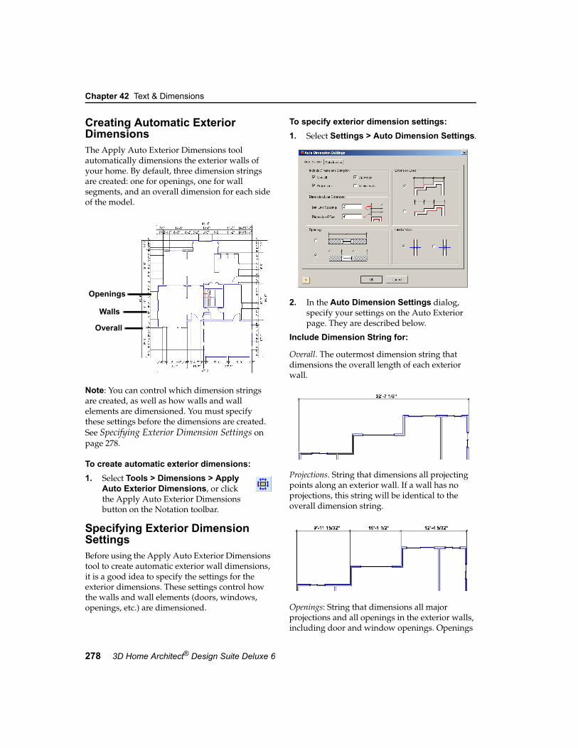
Chapter 42 Text & Dimensions
278 3D Home Architect® Design Suite Deluxe 6
Creating Automatic Exterior DimensionsThe Apply Auto Exterior Dimensions tool automatically dimensions the exterior walls of your home. By default, three dimension strings are created: one for openings, one for wall segments, and an overall dimension for each side of the model.
Note: You can control which dimension strings are created, as well as how walls and wall elements are dimensioned. You must specify these settings before the dimensions are created. See Specifying Exterior Dimension Settings on page 278.
To create automatic exterior dimensions:1. Select Tools > Dimensions > Apply
Auto Exterior Dimensions, or click the Apply Auto Exterior Dimensions button on the Notation toolbar.
Specifying Exterior Dimension SettingsBefore using the Apply Auto Exterior Dimensions tool to create automatic exterior wall dimensions, it is a good idea to specify the settings for the exterior dimensions. These settings control how the walls and wall elements (doors, windows, openings, etc.) are dimensioned.
To specify exterior dimension settings:1. Select Settings > Auto Dimension Settings.
2. In the Auto Dimension Settings dialog, specify your settings on the Auto Exterior page. They are described below.
Include Dimension String for:
Overall. The outermost dimension string that dimensions the overall length of each exterior wall.
Projections. String that dimensions all projecting points along an exterior wall. If a wall has no projections, this string will be identical to the overall dimension string.
Openings: String that dimensions all major projections and all openings in the exterior walls, including door and window openings. Openings
Overall
Walls
Openings

Creating Auto Interior Dimensions
User’s Guide 279
42
can be dimensioned on center, or to the outside edges (see the Openings area of the dialog).
Interior Walls: String that dimensions to all major projections and each interior wall that projects into the exterior wall. Interior walls can be dimensioned on center, or to the walls’ outside edges (this is specified in the Interior Walls area of the dialog).
Dimension Line DistancesDim Line Spacing: The spacing between successive dimension lines (when two or more strings are used).
Dimension Offset: The distance between the first dimension string and the walls.
OpeningsIf you are including a dimension string for openings, you can specify whether you want the openings to be dimensioned on center, or to the edges of the openings.
Extension LinesExtension lines extend from the dimension line toward the walls being dimensioned. In situations where dimension points are not parallel with each other, you can specify whether you want the extension lines to extend all the way to the dimension points, or whether you want them to line up with the shortest dimension point.
Interior WallsIf you are including the Interior Walls dimension string, you can specify whether you want the
walls to be dimensioned on center, or to the walls’ outside edges.
Creating Auto Interior DimensionsThe Auto Interior Dimensions tool automatically dimensions interior walls in your model.
To create automatic interior wall dimensions, you draw a base line through your model. Dimensions are created for any walls along that line (running in the same direction as the line).
Before creating automatic interior dimensions, you may want to specify the interior dimension setting, which determines exactly how the walls are dimensioned. See Specifying Interior Dimension Settings on page 280.
To create automatic interior dimensions:1. Select Tools > Dimensions > Auto
Interior Dimensions, or click the Auto Interior Dimensions button on the Notation toolbar.
2. Select a start point for the base line that is outside of the model.

Chapter 42 Text & Dimensions
280 3D Home Architect® Design Suite Deluxe 6
3. Select an end point for the base line that is outside of the model. Dimensions are created along that line.
4. Right-click and select Finish.
Specifying Interior Dimension SettingsIf you are using the Auto Interior Dimensions tool to create automatic interior wall dimensions, you can specify how you want the walls dimensioned before creating the dimensions. By default, walls are dimensioned on center. If you prefer you can dimension walls to one side or both sides.
To specify the auto interior dimension setting:1. Select Settings > Auto Dimension Settings.
2. In the Auto Dimension Settings dialog, select the Auto Interior tab.
3. Select the desired dimension option.
4. Click OK. You can now proceed with creating auto interior dimensions.
Creating Linear DimensionsA linear dimension is a horizontal or vertical dimension with extension lines going vertically (for a horizontal linear dimension) or horizontally (for a vertical linear dimension) to the origins of the extension lines, which define the endpoint of the dimension.
This tool is ideal for creating interior dimensions, or dimensions on a landscape plan.
1
2

Creating Aligned Dimensions
User’s Guide 281
42
To create linear dimensions:1. Select Tools > Dimensions > Linear
Dimensions, or click the Linear Dimensions button on the Notation toolbar.
2. Click a point in your drawing to begin the dimension line.
3. Move your mouse (you do not have to hold the mouse button down) to a second point and click. A dimension line including offsets, arrows and a numerical value is added to your drawing.
4. Move your mouse away from the dimension line to stretch your extension lines. When the extension lines are the desired length, click to finish the dimension.
Creating Aligned DimensionsAn aligned dimension is similar to a linear dimension, except it tilts to the same angle as the element you are dimensioning, making it the ideal choice for elements that are not horizontal or vertical.
To create aligned dimensions:1. Select Tools > Dimensions > Aligned
Dimensions, or click the Aligned Dimensions button on the Notation toolbar.
2. Click a point in your drawing to begin the dimension line.
3. Move your mouse (you do not have to hold the mouse button down) to a second point and click. A dimension line including offsets,
arrows and a numerical value is added to your drawing.
4. Move your mouse away from the dimension line to stretch your extension lines. When the extension lines are the desired length, click to finish the dimension.
Moving a Dimension LineYou can move a dimension line using the Move Dimension Line tool. When you move a dimension line, the extension lines stretch to accommodate the move.
To move a dimension line using the Move Dimension Line tool:1. Select the dimension.
2. Right-click and select Move Dimension Line, or select Edit > Modify Elements > Move Dimension Line.
3. Click any point to serve as the base point for the move.
4. Move your mouse in the direction you want to move the dimension line.
5. Click to finish the move.
Stretching DimensionsYou can make a dimension longer or shorter, or stretch either of its extension lines. When you stretch the length of a dimension, the dimension value updates automatically to reflect the new length.
To adjust the length of a dimension:1. Select the dimension.
2. Click on one of the lower extension grab handles, then drag the dimension to stretch it. Note that it is possible to stretch the extension line at the same time.
3. Release your mouse button.
Grabhandle

Chapter 42 Text & Dimensions
282 3D Home Architect® Design Suite Deluxe 6
To adjust the length of extension lines:1. Select the dimension.
2. Click the grab handle at the end of the extension line, then drag to stretch the extension line.
3. Release your mouse button.
Changing the Style of a DimensionYou can change a dimension’s line, arrow and text style by applying a different dimension style to it, or by editing dimension style properties.
To change the style of a dimension:1. Select the dimension. You can select multiple
dimensions using Shift+click.
2. Right-click and select Properties, or select Edit > Modify Elements > Properties.
3. In the Dimension Styles dialog, select the style you want to apply to the dimension.
To create a new dimension style, click the Add Item button, then type a name for the style and press ENTER.
To edit the properties of the currently selected dimension style, click Edit, then make your changes in the Edit Dimension Styles dialog. See Dimension Style Properties on page 282.
4. With the desired style selected, click Set Current.
5. Click OK.
Note: Dimension styles that are edited or added through inserted dimensions are saved with the current project only. If you want to save them in the dimension styles library, so they can be made available in other projects, see Saving
Customized Dimension Styles to the Dimension Styles Library File on page 367.
Deleting a DimensionYou can delete a dimension in a couple of easy steps.
To delete a dimension:1. Select the dimension.
2. Press the Delete key on your keyboard, or right-click and select Delete, or select Edit > Modify Elements > Delete.
Dimension Style PropertiesYou can control a dimension’s line, arrow and text style properties.
Anatomy of a Dimension
Lines and Arrows
Arrow TypeYou can specify an arrow type for dimensions and leaders (leaders are used with the Text with Leader tool). Choose an arrow, dot or tick for your arrow type.
ExtensionLine
Text
Arrow,Tick orDot
DimensionLine

Dimension Style Properties
User’s Guide 283
42
The properties below the Arrow Type selection window (Extension Offset, Dimension Offset, etc.) vary depending on the arrow type selected. As you make different selections, the dimension updates in the preview window.
Dimension Text
UnitsThe units (e.g. feet and inches) and precision used to display the dimension value.
Override system units: Uses the unit of measure specified in the Edit Dimension Styles dialog instead of the unit of measure specified in the program settings.
Type: Choose from Feet-Inches, Millimeters, Centimeters, Meters or Inches.
Precision: For Feet-Inches, the choices are whole units (0, 1/2, 1/4 and so on). For metric units, the choices are number of decimal places you can use.
Text StyleRefers to the font, font style, text height and color of the dimension text. Click Text Style to select a style.
Vertical Text PositionThis is the vertical position of the dimension text relative to the dimension line.
Vertically Centered: Text is placed inside the dimension line.
Horizontal Text: Forces the dimension text to always be horizontal, regardless of the dimension line's angle.
Above Dimension Line: Text is placed above the dimension line.
Distance: Distance between the text and the dimension line when placing text above the dimension line.
Horizontal Text PositionThis is the position of the dimension text relative to the ends of the dimension line.
Centered: Centers the text inside the dimension line.
Distance from first end: Places the text a specific distance from the first end of the dimension. Specify the distance in the Distance edit box.
Distance from the second end: Places the text a specific distance from the second end of the dimension. Specify the distance in the Distance edit box.
Line StylesYou can select a different line style for the dimension line, extension lines and arrows. A line style determines the line type and color.
To assign a different line style to a dimension component, select the component in the left pane, then select the desired line style in the right pane.
For information about creating custom line styles, see the Linestyles chapter on page 355.


285
Chapter
3D Home Architect® Design Suite keeps track of all the materials you use to build your home as you design it. You can generate a project estimate with a single mouse click. The resulting estimate is displayed in a detailed spreadsheet that can be saved and printed. You can even choose what locations you want included in the estimate.
Sample unit prices are provided for your convenience, but you can specify custom pricing directly from your suppliers. The grand total is calculated for you automatically, making estimating a breeze!
Project Estimate

Chapter 43 Project Estimate
286 3D Home Architect® Design Suite Deluxe 6
Generating a Project EstimateYou can view an accurate project estimate at any time during a design session. The estimate includes a list of materials, the quantities used, and pricing. The estimate is always up-to-date and reflects your project in its current state.
To generate a project estimate:1. Select Tools > Calculate/Estimate >
Generate Project Estimate.
By default, the estimate is shown in Microsoft® Excel XLS spreadsheet format. You can switch it to a standard column report format, which can be saved as a TXT file. If you want you can remove the grid lines from the display.
Materials are grouped by location, and there is a terrain category for landscaping materials. You can choose to omit selected locations from the estimate if you want.
The estimate can be printed and saved.
To switch to a standard column report format:1. In the Generate Project Estimate dialog,
select Standard Report Form from the report form drop box.
To turn grid lines off:1. In the Generate Project Estimate dialog,
select View > Show Grid.
To filter locations from the estimate:1. In the Generate Project Estimate
dialog, click the Filter Report button beside the report form drop box.
2. To omit a location and its elements from the project estimate, click the location’s filter icon. You can omit landscaping elements from the report by filtering the terrain out.
3. Click OK. The estimate is updated.
To print the estimate:1. In the Generate Project Estimate
dialog, select File > Print, or click the Print button to the left of the report form drop box.
2. In the Print dialog, select the printer you want to use, then click Print.
To save the estimate:1. In the Generate Project Estimate dialog,
select File > Save and Close, or click the Save and Close button at the bottom of the dialog.
Note: By default, the estimate is saved in the same directory where the project is saved.

Opening a Saved Estimate
User’s Guide 287
43
To save using a different file name or save location:1. Click the Browse button next to the
Report File edit box at the bottom of the Generate Project Estimate dialog.
2. In the Report Filename dialog, select the location where you want to save the estimate.
3. In the File name edit box, type the name you want to save under.
4. Click Save. The estimate is saved under the specified name and location.
To open the estimate in the associated editor:1. Select File > Open with Associated Editor.
If you haven’t saved the estimate yet, it is saved for you. The estimate is then opened in the associated editor. For estimates in the XLS format, the estimate opens in Microsoft® Excel. For estimates in the Standard Report (TXT) format, the estimate opens in a text editor such as Notepad.
To close the Generate Project Estimate dialog:1. Select File > Exit, or click the Close button in
the top right corner of the dialog.
Opening a Saved EstimateOnce you have saved an estimate, you can open it any time in its associated editor (Microsoft® Excel or Notepad). You can then edit and print the estimate if you want.
To open a saved estimate:1. Select Tools > Calculate/Estimate > View
Project Estimate.
2. Click the Browse button, then locate the file to open.
3. Click Open. XLS files open in Microsoft® Excel, and TXT files open in a text editor such as Notepad.
Editing Material PricingMost elements have a default unit price set for them in their properties. These prices are used in the project estimate.
If you have already created your design, you can edit the prices of inserted elements by selecting them in the drawing, then editing their properties. Alternatively you can generate and save a project estimate, then edit the pricing in Microsoft® Excel or Notepad, depending on the report format you choose.
If you edit the price of any element in the catalog, the price change will affect all new insertions of the element.
To edit the price of an inserted element:1. Select the element in your drawing. You can
select multiple elements of the same type using Shift+click.
2. Right-click and select Properties, or select Edit > Modify Elements > Properties.
3. In the properties dialog, select the Quantity tab.
4. Edit the value in the Price edit box. Note that prices are unit prices. For a carpet, for example, you would enter the price per square foot, not the price of the entire carpet.
5. Click OK in the properties dialog.

Chapter 43 Project Estimate
288 3D Home Architect® Design Suite Deluxe 6
To edit material pricing in the catalog:1. Select File > Catalogs > Catalog Manager,
or right-click and element in the catalog and select Catalog Manager.
2. From the Element drop box, select the element type you want to edit.
3. In the Select a Type window, select the group containing the element you want to edit.
4. In the Select an Element window, select the element to edit.
5. Select Catalog > Element Properties, or right-click and select Properties.
6. In the properties dialog, select the Quantity tab.
7. Edit the value in the Price edit box. Note that prices are unit prices. For a carpet, for example, you would enter the price per square foot, not the price of the entire carpet.
8. Click OK in the properties dialog.
9. Click OK.

289
Chapter
3D Home Architect® Design Suite incorporates powerful 3DTrueView™ rendering technology. 3DTrueView™ rendering adds light and shadow to a textured 3D view to achieve stunning, photo-realistic images of both the interior and exterior of your home. These images can be printed directly from the screen. You can also choose to save the rendered image to a bitmap (BMP) or JPG file that you can then open in most graphic editing applications.
Creating a 3DTrueView™ rendering involves nothing more than a single mouse click. Just sit back and watch your design come to life!
3DTrueView™

Chapter 44 3DTrueView™
290 3D Home Architect® Design Suite Deluxe 6
How 3DTrueView™ Rendering WorksA rendered view is a photo realistic view that includes light and shadows. When you render a 3D scene, the program performs a series of lighting calculations to determine the lighting in a scene. These are also called radiosity calculations. Once a final result is met, the scene is ray traced, or rendered. Ray tracing works by tracing the path taken by a ray of light through the scene, and calculating the ray’s reflection, refraction, or absorption whenever it intersects an element in the scene.
Material properties define how light reflects off a surface. Direct light and ambient light levels define the light that is reflected. Direct light is light that is emitted from light fixtures. It has a specific color, intensity and direction. Ambient light can be thought of as a general level of light that is everywhere in the scene. Every light in a scene contributes to the overall ambient light in a scene.
The first part of the radiosity process involves finding those element surfaces that are visible to direct light and calculating how much light is transferred to each element. Some elements will receive more light than others depending on their surface properties, and different surfaces will reflect different amounts of light. Still, each element will absorb some of the light, so the total amount reflected back into the scene will be less than that emitted by the light fixtures.
The next part of the process involves finding the element that reflects the most light, and repeating the process. The element is considered a secondary light source, so we need to calculate how much of its light is transferred to other elements in the scene. The process is repeated, one step at a time, until the amount of light remaining in the scene is negligible in comparison to the light originally emitted by the light fixtures. We then say that the radiosity calculations have converged to a solution, and that’s when ray tracing begins.
Setting the Viewpoint for the SceneWhen you create a 3DTrueView™ rendering, your model is captured at the angle currently shown on the screen. In most cases, the best type of view for 3DTrueView™ rendering is a Perspective view, because it is the most realistic. For information about 3D viewing, see 2D and 3D Viewing on page 27. Specific topics you might want to look at:
• Viewing in 3D on page 29• Changing Your Viewpoint on page 322• Selecting a Preset Camera Angle on page 324• Changing the Viewing Field Angle on
page 325
Setting the SceneEven though creating a 3DTrueView™ rendering involves nothing more than a mouse click, there are a few things you should consider beforehand.
Note: It doesn’t matter what display mode (wireframe, patterned, etc.) you’re currently in. 3DTrueView™ renderings will always be textured.
Exterior ShotsIf you want to do an exterior shot, the most important factor to consider is sunlight. This is determined by your global position and time of day. By adjusting these settings, you control how much sunlight is in the scene, and from what angle it shines. See Defining Your Location and Time of Day on page 291.
Night ShotsTo create a night shot, you need to first set your background to a night scene. See Selecting a Background for 3D Views on page 327. Once your background is set, all you need to do is set the time to a time of day when there is no sun. If you do want to create a night shot, you will probably want to insert some exterior lighting in your design. See Inserting Landscape Lighting on page 228.

Defining Your Location and Time of Day
User’s Guide 291
44
Interior ShotsWhen creating interior shots, light comes from light fixtures that you have inserted in the room, and can also come through the windows if it is daytime. You can turn lights on and off as well as change their light bulbs for different light intensity and effect. For information about interior light fixtures, see Interior Lighting on page 127. To speed up the rendering process, you may want to turn off daylight temporarily so that only light from light fixtures is considered in the calculation. This is ideal when a room has small or covered windows, or no windows at all. See Turning Daylight Off on page 294.
Defining Your Location and Time of DayYou can define where your model is located in the world, as well as set the time of day. This determines how much daylight there will be in the scene.
To define your location and time of day:1. Select View > 3DTrueView >
3DTrueView Options, or click the 3DTrueView Options button on the 3DTrueView toolbar.
2. In the Program Settings dialog, select the Global Settings tab.
3. Select a country and city from the appropriate drop boxes. You can add or edit
a city if needed. Just click the Add City or Edit City button. You will need to know the longitude, latitude and time zone of the city. You can save new or edited cities to the city template for use in other projects if you want.
4. To set the month and day, select a month by clicking the arrows on the month bar at the top of the calendar, then click a number on the calendar.
5. To set the time of day, enter a time in the Time edit box, or use the slider to select a time. Enable either the am or fm radio button. Clicking Set Current Time reads the current time set in your computer system and defaults to the next smallest 5-minute increment of time. For example, 12:04 becomes 12:00.
6. To keep track of changes in time due to daylight savings, enable the Daylight Saving check box.
7. To set the angle from True North, enter a value in the Angle from True North edit box. This is the “geographic” North, as opposed to the “magnetic” North which you see on a compass. The value you specify determines where North is on your screen, and affects the angle of the sun for daylight rendering. The number in degrees that you enter is in relation to the 90° perpendicular orientation of your drawing. A value of 1º makes the top of the screen North. A value of 90º makes the top of the screen East, and the left side of the screen North.
For more information, see “Specifying the Angle of True North” in the Online Help (enter the keywords “true north”).

Chapter 44 3DTrueView™
292 3D Home Architect® Design Suite Deluxe 6
It is assumed that information regarding building orientation to True North can be taken from, or calculated from, a surveyor's certificate. However, True North can be cal-culated from a Magnetic North reading taken at your building site. For more information, see “Calculating True North from Magnetic North” in the Online Help (enter the key-words “true north”).
8. Click OK.
To save new or edited cities:1. On the Global Settings page of the Program
Settings dialog, click the Save button below the city list.
2. In the Save As dialog, select the timezone.cty file in the program’s templates folder.
3. Click Save.
4. Click Yes to replace the original city template.
To load a saved city template into other projects:1. On the Global Settings page of the Program
Settings dialog, click the Load button below the city list.
2. In the Open dialog, select the timezone.cty file in the program’s Templates folder.
3. Click Open. The city list is updated automatically.
Creating a 3DTrueView™ RenderingCreating a photo realistic 3DTrueView™ rendering involves only a simple menu selection or mouse click. Rendered views are displayed instantly on the screen once they’ve been calculated. If you enable the Render to File option in your render options, the image will also be
saved to a BMP or JPG file for later access. For more information see Saving a 3DTrueView™ Rendering to a File on page 295.
To create a 3DTrueView rendering:1. Make sure you have set the 3D scene exactly
how you want it.
2. Select View > 3DTrueView > Render 3DTrueView, or click the Render 3DTrueView button on the 3DTrueView toolbar. The solution begins. Before the rendered view is generated, the program goes through a process of calculating light in the scene. These are called radiosity calculations. Basically, it determines how much light is given off by the sun or by lighting fixtures, and how much light is reflected off the surface of elements. The view is updated at regular intervals during these calculations. A dialog appears on the screen that shows you the progression of the radiosity calculations.
If you click Stop during the solution stage, radiosity calculations will stop, and the scene will be instantly rendered. This may be fine if the process seems to be taking a long time, but you may not get the result you want.
3. Once the radiosity calculations are complete, rendering begins. Please wait while the image is generated.
Once the rendering is complete, it fills your current view window. The Rendering 3DTrueView dialog tells you that the image is complete.

Adjusting the Rendering Quality
User’s Guide 293
44
At this point you can print the view if you want.
4. When you are finished viewing the 3DTrueView™ rendering, click Close in the Rendering 3DTrueView dialog. The view returns to its original, pre-rendered state.
If you selected the Render to File option before rendering, the image is saved in the same directory your project is located in. For more information, see Saving a 3DTrueView™ Rendering to a File on page 295.
Adjusting the Rendering QualityBy default, the quality level chosen for 3DTrueView™ renderings is Level 1 - Lowest (fastest). You can select an increased quality level before rendering if you want. Note that the higher level of quality you choose, the longer the rendering process takes.
To adjust the rendering quality:1. Select View > 3DTrueView >
3DTrueView Options, or click the 3DTrueView Options button on the 3DTrueView toolbar.
2. In the Program Settings dialog, select the Rendering tab.
3. Select the quality level you want from the Quality Level drop box.
4. Click OK.
Changing the Refresh Rate During Lighting CalculationsAs the program performs lighting calculations, the view updates at regular intervals to reflect calculations up to that point. You can change the interval at which the view refreshes by increasing or decreasing the number of steps between visual updates.
To change the refresh rate during radiosity calculations:1. Select View > 3DTrueView >
3DTrueView Options, or click the 3DTrueView Options button on the 3DTrueView toolbar.
2. In the Program Settings dialog, select the Rendering tab.
3. Edit the value in the Change Display Every _ Steps edit box. Fewer steps increase the frequency of visual updates, but can increase rendering time.
4. Click OK.
Adjusting the Brightness of the Rendered ImageThe program's "virtual camera" works in a manner similar to actual point-and-shoot cameras. It automatically calculates the correct "exposure" for the lighting situation and produces a view with infinite depth of field (i.e. everything is in focus). However if, in exceptional circumstances, you want to brighten or darken a rendering, you can use the Image Brightness option to manually override the automatic exposure. Brightness can be increased or decreased.
To adjust image brightness:1. Select View > 3DTrueView >
3DTrueView Options, or click the 3DTrueView Options button on the 3DTrueView toolbar.
2. In the Program Settings dialog, select the Rendering tab.
3. Specify the amount you want to increase or decrease the brightness in the Image Brightness edit box, or use the arrow buttons to scroll up or down. A positive value increases the brightness, while a negative values decreases it.
4. Click OK.

Chapter 44 3DTrueView™
294 3D Home Architect® Design Suite Deluxe 6
Turning Daylight OffBy default, daylight is included in radiosity calculations, even for indoor scenes (light can come through a window). You can turn daylight off if you want. This basically omits daylight from the lighting calculations, and can speed up rendering.
Note: The Enable Daylight option should always remain on for exterior shots, even if it is a night shot. If you want to create a night shot, change your time of day instead. See Defining Your Location and Time of Day on page 291.
To turn daylight off:1. Select View > 3DTrueView >
3DTrueView Options, or click the 3DTrueView Options button on the 3DTrueView toolbar.
2. In the Program Settings dialog, select the Rendering tab.
3. Uncheck the Enable Daylight check box.
4. Click OK.
Using Antialiasing to Reduce Jagged EdgesAntialiasing blends pixels in areas where two colors or two materials meet to reduce artifacts (or “stair steps”) and produce a more natural look to the scene. By default, antialiasing is disabled to increase rendering speed. You can select varying levels of antialiasing.
To use antialiasing:1. Select View > 3DTrueView >
3DTrueView Options, or click the 3DTrueView Options button on the 3DTrueView toolbar.
2. In the Program Settings dialog, select the Rendering tab.
3. Use the up arrows key next to the Antialiasing check box to increase the level of antialiasing. The higher the level, the cleaner the image, but the longer the rendering process takes. The highest level is 4.
4. Click OK.
Creating a Fog EffectTo create a fog effect in your rendering, you need to turn on the Fog option in your rendering settings before rendering the view.
To create a fog effect:1. Select View > 3DTrueView >
3DTrueView Options, or click the 3DTrueView Options button on the 3DTrueView toolbar.
2. In the Program Settings dialog, select the Rendering tab.
3. In the Effects area, check the Enable check box.
4. Enable the Fog radio button.
5. In the Density edit box, specify the desired thickness of the fog. The higher the percentage, the thicker the fog.
6. Click OK.
Creating a Smoke EffectTo create a smoke effect in your rendering, you need to turn on the Smoke option in your rendering settings before rendering the view.
To create a smoke effect:1. Select View > 3DTrueView >
3DTrueView Options, or click the 3DTrueView Options button on the 3DTrueView toolbar.
2. In the Program Settings dialog, select the Rendering tab.
3. In the Effects area, check the Enable check box.
4. Enable the Smoke radio button.
5. In the Density edit box, specify the desired thickness of the smoke. The higher the percentage, the thicker the smoke.
6. Click OK.

Adjusting the Light Coming from Light Fixtures
User’s Guide 295
44
Adjusting the Light Coming from Light FixturesTo adjust the color or intensity of light coming from a light fixture, you can add light bulbs, change a light bulb to a different type, adjust the intensity of the light, select a different color for the light, or turn a light off completely.
See the following topics:
Editing a Light Fixture’s Light Source on page 129
Turning a Light On or Off on page 130
Editing the Surface Properties of MaterialsDifferent materials have different finishes. Surface finishes include Dull, Low Gloss, Semi Gloss, High Gloss, Liquid, Fully Reflective, Partially Reflective, Shiny, Fully Transparent, Partially Transparent, and Varnished. The finish determines how much a material reflects, emits and absorbs light. These factors can affect the lighting in a rendered scene.
To edit the surface properties of an element’s materials:1. Select the element in your drawing.
2. Right-click and select Properties, or select Edit > Modify Elements > Properties.
3. In the properties dialog, select the Appearance tab.
4. On the Appearance page, click the Select button, or click the Texture swatch to access the Materials dialog.
5. In the Materials dialog, click the Rendered swatch to bring up the Edit Materials dialog.
6. To change the surface finish of the material (dull, shiny, etc.), make a selection from the drop box in the Surface Properties area. If you want to specify a custom surface finish, select Custom in the list, then click the Advanced button.
7. If creating a custom finish, specify its properties. These are described below.
Specular. Reflection that creates highlights on materials, making them appear shiny.
Emissive. The amount of light given off by a material. The more emissive a material is, the more self-luminous it appears.
Transparency. The degree to which a mate-rial is pervious to light.
Color Bleed. The degree to which different colors blend where they meet.
8. Click OK in the Edit Materials dialog.
9. Click OK in the Materials dialog.
10. Click OK in the properties dialog.
Saving a 3DTrueView™ Rendering to a FileRendered views are displayed instantly on the screen once they’ve been calculated. If you want the image to be saved to a file, you need to turn on the Render to File option in your render settings before creating the rendering. The image will be saved to a BMP or JPG file that you can open in most graphic editing applications.
To save a 3DTrueView rendering to a file:1. Select View > 3DTrueView >
3DTrueView Options, or click the 3DTrueView Options button on the 3DTrueView toolbar.
2. In the Program Settings dialog, select the Rendering tab.
3. In the Image Output area, enable the Render to File check box.
4. By default, rendered images are saved in the same directory your projects are stored in. By default, this would be the following directory:
C:\Documents and Settings\<Current User>\My Documents\Design Suite Deluxe 6\Projects
To select a different location to save your rendered image in, click the Browse button next to the current output folder path. In the Open dialog,

Chapter 44 3DTrueView™
296 3D Home Architect® Design Suite Deluxe 6
navigate to the folder where you want to store rendered images.
By default, the file has the same name as your project for easy identification. To specify a custom name, enter the name in the File Name edit box. You can select either BMP or JPG as your file format from the Files of type drop box.
5. Click OK.
Specifying the Output Size of Rendered ImagesBy default, 3DTrueView™ images fill the view window they are created from. If you enabled the Render to File option in your rendering settings, the image is also saved at that size. You can select another output size if you want.
To specify an output size for rendered images:1. Select View > 3DTrueView >
3DTrueView Options, or click the 3DTrueView Options button on the 3DTrueView toolbar.
2. In the Program Settings dialog, select the Rendering tab.
3. In the Image Output area, select the desired size from the Size drop box. The default selection is Current View Size, which saves the image at the size currently shown on the screen. Pre-defined sizes include 640 x 480, 800 x 600, and 1024 x 768. Selecting the Custom option lets you define a custom size by entering values in the Width and Height edit boxes.
4. Click OK.
Creating Multiple 3DTrueView™ Renderings in the Same ProjectIf you enable the Render to File option before creating a rendering, the image is saved to a BMP or JPG file in your projects directory. The file has the same name as your project. If you create another 3DTrueView™ rendering in the same project, the file from the previous rendering is overwritten.
If you want to create and save more 3DTrueView™ renderings within the same project, you need to specify a different output name for each new image before creating the rendering.
To create and save an additional 3DTrueView rendering:1. Select View > 3DTrueView >
3DTrueView Options, or click the 3DTrueView Options button on the 3DTrueView toolbar.
2. In the Program Settings dialog, select the Rendering tab.
3. In the Image Output area, make sure Render to File is checked.
4. Click the Browse button next to the current output folder path.
5. In the Open dialog, enter a name in the File name edit box that is different from any other images that you have saved. You can select either BMP or JPG as your file format from the Files of type drop box.
6. Click Open.
7. Click OK in the Program Settings dialog.
The next 3DTrueView™ rendering you create will be saved to the new file name.

Managing Files
Part 11
Opening, Saving & Printing page 299
Exporting Files page 305


299
Chapter
Once you have started and saved a project, you can work on it whenever you like. You can open a saved project by selecting the Open a Saved Project button in the startup dialog, or by selecting Open on the File menu if the program is already running. Once you have opened a project, you can edit, save, print and export it, as well as save it as a template for future projects.
You can have more than one project open at a time. If you have more than one project open, you can switch between projects using the Window menu.
As you edit your drawing, the changes you make are stored temporarily in your computer’s memory until you save them. The Save function saves the current project under its current name. You can use Save As to save a project under a different name, and Save All to save all currently open projects. You can also use the Save As tool to save a drawing as a template for use in future projects.
Opening, Saving & Printing

Chapter 45 Opening, Saving & Printing
300 3D Home Architect® Design Suite Deluxe 6
Opening a Saved ProjectYou can open a saved project (*.bld file) directly from the startup dialog that appears when you start the program. Just click Open a Saved Project, then select the project to open.
If the program is already running, you can open a saved project using the Open tool.
To open a saved project if the program is already running:1. Select File > Open, or click the Open
button on the Standard toolbar.
2. In the Open dialog, navigate to the location where you saved the project.
3. Select the project to open, then click Open.
Note: You can open drawings from version 5.0 or later of 3D Home Design Suite Professional, 3D Home Architect®, or 3D Home Landscape Designer.
Tip: If the project you want to open is one that your recently worked on, it may be listed in the recently used file list near the bottom of the File menu. Just select it to open it.
Viewing Sample PlansThe program ships with a number of sample projects that you can use to see what the program can do, and get design ideas. You can also use a sample project as a template for your own design project.
Sample projects are available for selection in the startup dialog when you launch the program. Just click View Sample Plans and select one from the list.
If the program is already running, you can open a sample project using the Open tool.
To open a sample plan if the program is already running:1. Select File > Open, or click the Open
button on the Standard toolbar.
2. In the Open dialog, navigate to the location where you installed the program, then select the Samples directory (e.g. C:\Program
Files\3D Home Architect\Design Suite Deluxe 6\Samples).
3. Select the project to open, then click Open.
Changing the Number of Files in the Recently Used File ListBy default, a maximum of four projects are listed in the recently used file list near the bottom of the File menu. You can increase or decrease this number if you want.
To change the number of files in the recently used file list:1. Select Settings > Program Settings or
click the Program Settings button on the Settings toolbar.
2. In the Program Settings dialog, select the General tab.
3. Type the maximum number of files to display in the Recently used file list edit box, or use the arrows to select a number. You can list a maximum of 9 files.
Repairing Damaged ProjectsOccasionally a drawing may become damaged, usually when drawing walls. The Repair Project tool scans the project for elements that have caused damage, and either fixes or removes them.
To repair a damaged project:1. Select File > Repair Project. If the recovery is successful, the following dialog box appears:
If the recovery is not successful, a dialog appears telling you why it was not successful.
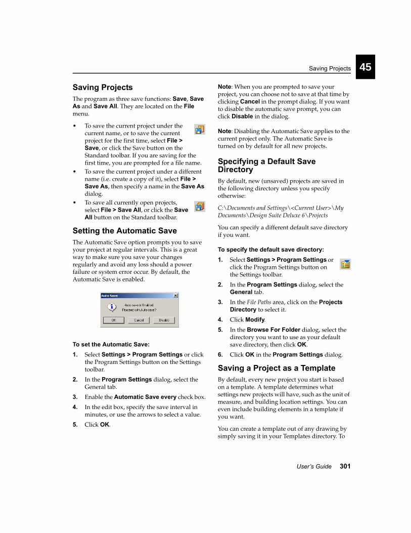
Saving Projects
User’s Guide 301
45
Saving ProjectsThe program as three save functions: Save, Save As and Save All. They are located on the File menu.
• To save the current project under the current name, or to save the current project for the first time, select File > Save, or click the Save button on the Standard toolbar. If you are saving for the first time, you are prompted for a file name.
• To save the current project under a different name (i.e. create a copy of it), select File > Save As, then specify a name in the Save As dialog.
• To save all currently open projects, select File > Save All, or click the Save All button on the Standard toolbar.
Setting the Automatic SaveThe Automatic Save option prompts you to save your project at regular intervals. This is a great way to make sure you save your changes regularly and avoid any loss should a power failure or system error occur. By default, the Automatic Save is enabled.
To set the Automatic Save:1. Select Settings > Program Settings or click
the Program Settings button on the Settings toolbar.
2. In the Program Settings dialog, select the General tab.
3. Enable the Automatic Save every check box.
4. In the edit box, specify the save interval in minutes, or use the arrows to select a value.
5. Click OK.
Note: When you are prompted to save your project, you can choose not to save at that time by clicking Cancel in the prompt dialog. If you want to disable the automatic save prompt, you can click Disable in the dialog.
Note: Disabling the Automatic Save applies to the current project only. The Automatic Save is turned on by default for all new projects.
Specifying a Default Save DirectoryBy default, new (unsaved) projects are saved in the following directory unless you specify otherwise:
C:\Documents and Settings\<Current User>\My Documents\Design Suite Deluxe 6\Projects
You can specify a different default save directory if you want.
To specify the default save directory:1. Select Settings > Program Settings or
click the Program Settings button on the Settings toolbar.
2. In the Program Settings dialog, select the General tab.
3. In the File Paths area, click on the Projects Directory to select it.
4. Click Modify.
5. In the Browse For Folder dialog, select the directory you want to use as your default save directory, then click OK.
6. Click OK in the Program Settings dialog.
Saving a Project as a TemplateBy default, every new project you start is based on a template. A template determines what settings new projects will have, such as the unit of measure, and building location settings. You can even include building elements in a template if you want.
You can create a template out of any drawing by simply saving it in your Templates directory. To

Chapter 45 Opening, Saving & Printing
302 3D Home Architect® Design Suite Deluxe 6
use the template in new drawings you need to select the template in your Startup options.
To create a template:1. Unless you have already created the drawing
you want to use as a template, start a new project (File > New).
2. Specify the settings you want to save with the template, such as your building locations and program settings. Note that any elements in your drawing will be saved as well, so unless you want these elements to appear in new projects, you should delete the elements from your drawing.
3. Select File > Save As.
4. In the Save As dialog, navigate to the program’s Templates folder (e.g. C:\Program Files\3D Home Architect\Design Suite Deluxe 6\Templates).
5. In the File name edit box, type a name for the template.
6. Click Save.
Selecting a Default Project TemplateBy default, new projects are based on a default template that ships with the program. If you chose to work in Imperial units during program installation, new projects will be based on the 1-Blank Project (ft & in).bld template, which is a blank drawing with measurements set to feet and inches. If you chose to work in Metric, new projects will be based on the template, which has its unit of measure set to millimeters. Each template contains three default building locations: Foundation, Ground Floor and Second Floor.
You can select a different template to use as the default template when starting new drawings. You can use one of the templates that ships with the program, or one that you have created yourself.
To select a default project template:1. Select Settings > Program Settings or
click the Program Settings button on the Settings toolbar.
2. In the Program Settings dialog, select the General tab.
3. In the Startup area, make sure the Startup using Project Template radio button is enabled.
4. Click the Browse button next to the current template name.
5. In the Open dialog, select the template you want to use from the Templates directory, then click Open.
6. In the Program Settings dialog, click OK.
Note: You need to start a new drawing to put the new template into effect.
Disabling the Use of TemplatesBy default, new projects are based on a template that determines the unit of measure used. Templates also have a few pre-defined settings, such as a set of default building locations.
If you prefer you can start new projects without using a template. If you choose to do this, new projects will be blank with no pre-defined settings.
To disable the use of templates:1. Select Settings > Program Settings or
click the Program Settings button on the Settings toolbar.
2. In the Program Settings dialog, select the General tab.
3. In the Startup area, enable the Do not use Project Template radio button.
4. Click OK.
Setting the Path to the Templates DirectoryBy default, the Templates directory is located in the 3D Home Architect Design Suite Deluxe 6 program group. If you have moved your Templates directory, or have chosen to store your

Selecting a Directory for Temporary Files
User’s Guide 303
45
templates in a different directory, you should reset the path to the template directory in your program settings. The path you set determines the default directory shown when you browse for templates in your Startup options on the General page of the Program Settings dialog.
To set the path to your templates directory:1. Select Settings > Program Settings or
click the Program Settings button on the Settings toolbar.
2. In the Program Settings dialog, select the General tab.
3. In the File Paths area, click on the Templates Directory to select it.
4. Click Modify.
5. In the Browse For Folder dialog, select the directory containing your templates, then click OK.
6. Click OK in the Program Settings dialog.
Selecting a Directory for Temporary FilesCertain functions of the program create temporary files which are stored in a directory on your computer system. By default, the path to the temporary directory is as follows:
C:\Documents and Settings\<Current User>\Local Settings\Temp
You can specify a different directory to store your temporary files in if you want.
To set a different temporary files directory:1. Select Settings > Program Settings or
click the Program Settings button on the Settings toolbar.
2. In the Program Settings dialog, select the General tab.
3. In the File Paths area, click on the Temporary Directory to select it.
4. Click Modify.
5. In the Browse For Folder dialog, select the directory you want to use as your default temporary files directory, then click OK.
6. Click OK in the Program Settings dialog.
Closing ProjectsProjects remain open until you close them or exit the program. You can close the active project without exiting the program. If you have more than one drawing open, make sure the drawing you want to close is the active one.
To close a drawing:1. Select File > Close, or click the Close
button on the Standard toolbar.
2. In the dialog, click Yes or No when you are asked to save changes.
3. If you haven’t named the project yet and you clicked Yes in the previous step, specify a name for the project in the Save As dialog, then click Save.
Printing DrawingsThe program uses the standard Windows Print routine with a few added features for your printing convenience.
To print a drawing:1. Select File > Print, or click the Print
button on the Standard toolbar.
2. In the Print dialog, specify your print settings.

Chapter 45 Opening, Saving & Printing
304 3D Home Architect® Design Suite Deluxe 6
Printer. Select a printer from the drop box. Click Properties to specify general printer properties.
Print Area. The All option prints the extents of your drawing, which is the portion of your drawing that currently contains elements. As you add new elements, the extents update automatically. The Currently Displayed option prints exactly what you see on the screen in the current view. If only part of your drawing is currently visible, only that part will appear in the printout.
Copies. Select the number of copies to print from the Number of copies drop box.
Scale. The Print to Scale option prints the current view according to its defined scale in the view properties, regardless of the paper size. The scale is the ratio of drawing units to real-world units. A scale of 1:1 (12" = 1'- 0") creates a view that is the same scale as the view in the main drawing window. A scale of 1:12 (1" = 1'- 0") creates a smaller-scale view. Note that if you change the scale, the model does not scale on the screen. It will only be scaled on paper when you print the drawing.
However, things like text and dimensions will scale on the screen because they are specified in real-world units, whereas the model on your screen is created using units that are only proportional to real-world units. Regardless of a view’s scale, things like text and dimensions will always print out at the size that was assigned to them at the time of insertion. For example, if you inserted text that had a 1/2” text height setting, the text will be 1/2” on paper, regardless of the view scale or what the text looks like on the screen.
To see a view’s defined scale, select Edit > View Properties, or right-click in the drawing area and select View Properties, or right-click on a view’s tab below the drawing area and select View Properties.
Note that the Print to Scale option will not work with most 3D views (unless they are elevation views), since 3D views cannot be scaled.
The Fit To Page option scales the drawing to fit the selected paper size. Note that this is the default setting for 3D views, since 3D views are not affected by changes in scale (unless they are elevation views).
Placement on Paper. If you select Lower left, the image is printed in the lower left corner of the paper. If you select Center on paper, the image is centered on the paper.
Graphics. Choose from three levels of print quality (150, 300 or 600 dpi). A higher resolution (600 dpi) produces graphic images that are sharper and show finer detail, while a lower resolution (150 dpi) permits faster printing and shows less detail.
3. Click OK.
Using Print SetupThe program uses the standard Windows Print Setup for printer and paper selection.
To select a printer and paper for output:1. Select File > Print Setup.
2. Choose the options you want.
3. Click OK.

305
Chapter
You can export your drawing to a variety of file formats including DXF, 3DS, WRL, BMP, JPG and TGA.
Exporting Files

Chapter 46 Exporting Files
306 3D Home Architect® Design Suite Deluxe 6
Exporting Your ModelThe Export 3D Model tool lets you export your drawing to three file formats:
• AutoCAD Basic DXF (*.dxf)• Autodesk 3D Studio (*.3ds)• VRML (*.wrl)
To export your model:1. Select File > Export > 3D Model.2. In the Save As dialog, click on the Save as
type drop box and select the file format you want to export to.
3. Locate the directory where you want to save the exported file.
4. In the File name edit box, type a file name.
5. Click Save. A dialog appears confirming the model has been exported successfully.
6. Click OK.
Exporting the Current ViewThe Export 2D Image tool lets you export the current view to a BMP, JPG or TGA file.
To export a view:1. Select File > Export > 2D Image.
2. In the Save As dialog, click on the Save as type drop box and select the file format you want to export to.
3. Locate the directory where you want to save the exported file.
4. In the File name edit box, type a file name.
5. Click Save. The Export View dialog appears:
6. From the Color drop box, select the desired color setting. Choose from Grayscale, 256 Color, High Color (16-bit), High Color (24-bit) or True Color (32-bit).
7. From the Size drop box, select the desired output size. By default, Current View is selected, which saves the image at the size currently shown on the screen. You can choose from a list of preset sizes, or select Custom and enter the desired values in the Width and Height edit boxes.
8. Click Save. The view is exported.

CustomizationPart 12
Screen Settings page 309
Managing View Windows page 315
Custom Viewing page 321
Catalogs & Elements page 333
Materials, Colors & Patterns page 347
Line Styles page 355
Text & Dimension Styles page 361
Light Sources page 369
Wizard Configurations page 375


309
Chapter
3D Home Architect® Design Suite’s screen environment is totally customizable, so you can create a work environment that is both functional and comfortable according to your personal needs.
This chapter describes how to display, hide and move screen components, change the color of the drawing area and toolbar areas, and improve graphics display.
Screen Settings

Chapter 47 Screen Settings
310 3D Home Architect® Design Suite Deluxe 6
Displaying/Hiding ToolbarsThere are 12 toolbars available for display. (By default, not all of them are displayed.) You can hide or show individual toolbars by setting your workspace options. When you display a toolbar, it is displayed in one of the toolbar areas which are located directly above and below the drawing area. Note that if you hide a toolbar that is displayed in a tab, the tab is hidden from view as well.
To hide or show toolbars:1. Select Settings > Toolbars.
2. Check the toolbars that you want to display, and uncheck those that you do not want to display.
3. Click OK.
Tip: If a toolbar is currently floating freely on the screen, you can hide it by clicking the close button on its title bar, or right-clicking its title bar and selecting Hide.
Displaying Toolbars in Tabbed FormatYou can display any toolbar in tabbed format, meaning a tab will be added to the row of toolbar tabs below the menu bar.
To display a toolbar in a tab:1. Select Settings > Toolbars.
2. Enable the check box of the toolbar you want to display in a tab.
3. Enable the toolbar’s Tabbed check box.
4. Click OK.
Displaying Toolbars in a Non-tabbed FormatBy default, the Building, Interiors, Landscape and Terrain toolbars are displayed in tabs below the menu bar. You can change any tabbed toolbar to be displayed as a non-tabbed, free-standing toolbar.
To display toolbars in non-tabbed format:1. Select Settings > Toolbars.
2. Make sure the check box of the toolbar you want to display is enabled.
3. Disable the toolbar’s Tabbed check box.
4. Click OK.
Changing the Background Color of ToolbarsYou can change the general background color of individual toolbars by changing your workspace options. This applies to both tabbed and free-standing toolbars.
To change the background color of toolbars:1. Select Settings > Toolbars.
2. Click the Color box next to the toolbar you want to change.
3. In the Color dialog, select or create the desired color, then click OK.
4. Click OK in the Program Settings dialog.
Changing the Color of Toolbar AreasThe program has two toolbar areas: one directly above the drawing area, and one directly below the drawing area. By default, the background color of these areas is dark blue. You can change this color in your workspace options.
To change the color of toolbar areas:1. Select Settings > Toolbars.
2. Click the colored box next to the Toolbar Areas option.
3. In the Color dialog, select or create the desired color for your toolbar areas, then click OK to return to the Program Settings dialog.
4. Click OK.
Moving ToolbarsYou can drag any non-tabbed toolbar to any location on the screen. At window edges, the toolbar will automatically dock itself according to

Displaying/Hiding the Catalog Panel
User’s Guide 311
47
the location. For example, if you drag it to the right edge of the screen, it will assume a vertical orientation.
If you drag it into the drawing window, it will float freely. You can then move it by dragging it by its title bar.
To move a toolbar:1. Click and hold your mouse button over the
left grip end of the toolbar (or its title bar if it is currently in the drawing area).
2. Drag the toolbar to the desired location.
3. Release the mouse button.
Displaying/Hiding the Catalog PanelBy default, the catalog panel is displayed on the right side of the screen, as it is an essential component of the program. You can hide the catalog panel from view if you want.
To display or hide the catalog panel:1. Select Settings > Toolbars. Or, select
Settings > Program Settings (or click the Program Settings button on the Settings toolbar) and select the Workspace tab in the Program Settings dialog.
2. In the Tool Display area, check or uncheck the Catalog Panel check box.
3. Click OK.
Resizing the Catalog PanelWhen the catalog panel is docked at one side of your screen, you can make it narrower or wider by simply clicking and dragging its edges. If you have moved the catalog panel away from the edge, so it is free-floating, you can resize it by clicking and dragging its corners.
To resize the catalog panel if it is docked:1. Position your pointer over the panel's left
outside edge. (If you have moved the catalog panel to the left side of the screen, position your pointer over the right edge.) Watch for the Resize cursor to appear.
2. Click and drag the edge of the panel to stretch it in the desired direction.
3. Release your mouse button.
To resize the catalog panel if it is free-floating:1. Position your pointer over one of the panel’s
corners.
2. Click and drag to stretch the panel.
3. Release your mouse button.
Moving the Catalog PanelIf the catalog panel is docked on one side of the screen, you can move it by clicking and dragging its outside edge. If you move a panel to the side of the screen, it will automatically dock itself to the edge of the screen. Otherwise, the panel is displayed in a free-floating window.
If the panel is free-floating, you can move it by clicking and dragging its title bar.
Toolbar Grip End
Resizecursor

Chapter 47 Screen Settings
312 3D Home Architect® Design Suite Deluxe 6
To move the catalog panel when it is docked:1. Position your pointer over the panel’s
outside edge (the edge that is at the side of the screen). Watch for the Move cursor.
2. Click and drag the panel to move it.
3. Release your mouse button.
To move the catalog panel when it is free-floating:1. Position your pointer over the panel’s title
bar.
2. Click and drag the panel to move it.
3. Release your mouse button.
Displaying/Hiding the Status BarThe Status bar can be toggled on and off as needed.
To display/hide the Status bar:1. Select Settings > Toolbars. Or select
Settings > Program Settings and select the Workspace tab in the Program Settings dialog.
2. In the Tool Display area, select or clear the Status Bar check box.
3. Click OK.
Changing the Background Color of the Drawing WindowBy default, the color of the main drawing window is white. You can select a different color if you like. Note, however, that selecting a different background color can make some elements difficult to see depending on their color settings.
To change the background color of the drawing window:1. Select Settings > Toolbars. Or, select
Settings > Program Settings (or click the Program Settings button on the Settings toolbar) and select the Workspace tab in the Program Settings dialog.
2. Click the colored box next to the Background option.
3. In the Color dialog, select or create the desired color for your drawing area, then click OK to return to the Program Settings dialog.
4. Click OK.
Hardware AccelerationThe Hardware Acceleration option controls how your screen responds during a work session. By default, hardware acceleration is enabled.
Hardware acceleration increases the speed of your graphics display. When hardware acceleration is enabled, your computer takes advantage of any installed graphics card that supports hardware acceleration. If no card exists, and the Hardware Acceleration option is still enabled, your computer automatically defaults to slower software acceleration, which uses the Windows implementation of OpenGL. For detailed information about OpenGL, see the OpenGL topic in the online help.
In most cases, it is best to enable the Hardware Acceleration option. However, problems sometimes arise with graphics cards on which hardware acceleration is poorly implemented. If you are experiencing display-related problems like scrambled line patterns, see the next topic, Improving Graphics Display.
Movecursor

Improving Graphics Display
User’s Guide 313
47
To enable or disable hardware acceleration:1. Select Settings > Program Settings or
click the Program Settings button on the Settings toolbar.
2. In the Program Settings dialog, select the General tab.
3. In the Graphics area, check or uncheck the Hardware Acceleration check box.
4. Click OK.
Improving Graphics DisplayThe type of graphics card you have can affect the way the program’s graphics are displayed on the screen. If the display seems unstable or contains some graphic artifacts (e.g. large pixels), here are some tips on how you may be able to improve the display:
1. Disable pre-selection. Pre-selection highlights elements when you hover your pointer over them, and displays tooltips. See Disabling Pre-Selection on page 23.
2. Lower your screen resolution (to 1024 x 768, for example). To access this setting, right-click your Windows desktop and select Properties. In the Display Properties dialog, select the Settings tab.
3. Lower your color setting in Windows. For example, if your colors are set to True Color (32 bit), change the setting to High Color (16 bit). To access this setting, right-click your Windows desktop and select Properties. In the Display Properties dialog, select the Settings tab.
4. If the above three methods fail to improve the graphics display, disable Hardware Acceleration in your Program Settings. See Hardware Acceleration on page 312.


315
Chapter
By default, your project has one view window called Standard. You can create additional view windows using the View Manager. Each view window can have different view settings. For example, you may want to keep the wireframe 2D plan view in the Standard view window, and create a new view window containing a 3D view of the model.
When you create new view windows, you can switch between open view windows using the Window menu. You can also turn your view tabs on, which will display a row of tabs below the drawing area. This provides instant point-and-click access to all your view windows.
You can display multiple view windows at the same time using the Tile Open Views and Cascade Open Views tools. View windows can be moved, resized and closed to create the exact arrangement you want.
This chapter describes all the functions of the View Manager, how to navigate between view windows, and arrange view windows.
Managing View Windows

Chapter 48 Managing View Windows
316 3D Home Architect® Design Suite Deluxe 6
Using the View ManagerThe View Manager contains a listing of view windows and lets you open, close, create, and edit views.
By default, your project contains one view window called Standard. The scale of the view in this window is 1:48, or 1/4” = 1’-0”.
Using the New View tool you can create new view windows. Each window can have different view settings. For example, you may want to display a wireframe, 2D plan view in the Standard view window, and create a new view window containing a 3D view of your model.
Using the Window menu or view tabs you can switch between view windows as needed to see different views of your design. This can eliminate the need to constantly change the current view settings to see a particular view of your design. You can even display two or more view windows at the same time.
You can edit the name and scale of views listed in the View Manager.
To access the View Manager:1. Select View > View Manager.
Creating New View WindowsBy default, your project contains one view window called Standard. You can use the View Manager to create new view windows and specify different view settings for each window. For example, you may want to create a view window dedicated to 3D viewing only.
Views are stored in groups for easy organization and navigation. You can add view windows to the default group, or create your own groups if you want. For example, you might want to create a group for 3D views only, then add a set of 3D view windows to that group.
To create a new group in the View Manager:1. Select View > View Manager.2. Click the Add Group button, or right-
click in the View Manager’s view window and select Add Group. A group is added to the list.
3. Right-click the new group and select Rename.
4. Type a name for the group, then press ENTER.
To rename a group in the View Manager:1. Right-click the group and select Rename.
2. Type the new name, then press ENTER.
To delete a group in the View Manager:1. Make sure the group contains no views.
2. Select the group and click the Delete button, or right-click the group and select Delete.
To create a new view in the View Manager:1. Select the group you want to add the view to.
2. Click the New View button, or right-click and select New View.
3. In the View Properties dialog, type a name for the view window, then select a print scale for the view.
The scale is the ratio of units on paper to real-world units. If the scale is set to 1:1 (12" = 1'-
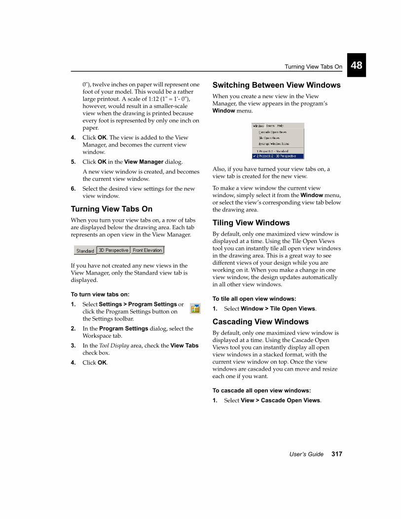
Turning View Tabs On
User’s Guide 317
48
0"), twelve inches on paper will represent one foot of your model. This would be a rather large printout. A scale of 1:12 (1" = 1'- 0"), however, would result in a smaller-scale view when the drawing is printed because every foot is represented by only one inch on paper.
4. Click OK. The view is added to the View Manager, and becomes the current view window.
5. Click OK in the View Manager dialog.
A new view window is created, and becomes the current view window.
6. Select the desired view settings for the new view window.
Turning View Tabs OnWhen you turn your view tabs on, a row of tabs are displayed below the drawing area. Each tab represents an open view in the View Manager.
If you have not created any new views in the View Manager, only the Standard view tab is displayed.
To turn view tabs on:1. Select Settings > Program Settings or
click the Program Settings button on the Settings toolbar.
2. In the Program Settings dialog, select the Workspace tab.
3. In the Tool Display area, check the View Tabs check box.
4. Click OK.
Switching Between View WindowsWhen you create a new view in the View Manager, the view appears in the program’s Window menu.
Also, if you have turned your view tabs on, a view tab is created for the new view.
To make a view window the current view window, simply select it from the Window menu, or select the view’s corresponding view tab below the drawing area.
Tiling View WindowsBy default, only one maximized view window is displayed at a time. Using the Tile Open Views tool you can instantly tile all open view windows in the drawing area. This is a great way to see different views of your design while you are working on it. When you make a change in one view window, the design updates automatically in all other view windows.
To tile all open view windows:1. Select Window > Tile Open Views.
Cascading View WindowsBy default, only one maximized view window is displayed at a time. Using the Cascade Open Views tool you can instantly display all open view windows in a stacked format, with the current view window on top. Once the view windows are cascaded you can move and resize each one if you want.
To cascade all open view windows:1. Select View > Cascade Open Views.

Chapter 48 Managing View Windows
318 3D Home Architect® Design Suite Deluxe 6
Returning to a Maximized ViewIf you have tiled or cascaded your open view windows, you can return to a maximized view (where only one view window is visible) by maximizing one of the open view windows.
To maximize a view window:1. Click the Maximize button in the view
window you want to maximize.
Restoring the Previous Arrangement of View WindowsIf you tiled, cascaded or arranged your view windows, then maximized one of them, you can use the Restore Down button to return to the view window arrangement that was displayed before you used the Maximize button.
To restore the previous arrangement of view windows:1. Click the Restore Down button in the top
right corner of the current view window.
Closing View WindowsBy default, the Standard view window is open when you start a project. Also, every time you create a new view window in the View Manager, that window is automatically opened for you. You can close individual view windows using the View Manager’s Close View button, or by clicking the view window’s Close button.
To close a view window from within the window itself:1. Click the Close button in the top right corner
of the view window.
To close a view window using the View Manager:1. Select View > View Manager.2. Select the view you want to close.
3. Click Close View.
Opening View Windows that You Have ClosedIf you have closed a view window either through the View Manager or by clicking a view window’s Close button, you can open it again using the View Manager’s Open View button.
To open a view window:1. Select View > View Manager.2. Select the view you want to open.
3. Click Open View. The view window becomes the current view window. It appears on the Window menu as well as on a view tab if you have view tabs turned on.
Renaming a View WindowYou can edit the name of a view window as it appears in the View Manager, in the program’s title bar, and on the view tabs. You can do this in the View Manager, or by accessing the view window’s properties.
To rename a view window when it is the current view window:1. Select View > View Properties, or right-click
in the view window and select View Properties.
2. In the View Properties dialog, type the new name in the Name edit box.
Restore Down
Application window controls
View window controls
Close
Application window controlsView window controls

Editing the Print Scale of a View
User’s Guide 319
48
3. Click OK.
To rename a view window in the View Manager:1. Select View > View Manager.2. Right-click the view you want to rename,
then select Rename. Or, select the view to rename and click the Properties button.
3. Type the new name and press ENTER.
4. Click OK.
Editing the Print Scale of a ViewYou can edit the print scale of a view by accessing the view’s properties.
A view’s print scale is the ratio of units on paper to real-world units. If the scale is set to 1:1 (12" = 1'- 0"), twelve inches on paper will represent one foot of your model. This would be a rather large printout. A scale of 1:12 (1" = 1'- 0"), however, would result in a smaller-scale view when the drawing is printed because every foot is represented by only one inch on paper.
Note that if you change the print scale, your 2D plan does not scale on the screen. It will only be scaled on paper when you print the drawing. The scale you specify in a view window’s properties has a direct link to the Print to Scale option in the Print dialog.
Changing the print scale has no effect in 3D views, neither on the screen nor in printouts, unless it is an elevation view. This is because a model being viewed in 3D does not have concrete measurements like a flat, 2D view has.
Things like text and dimensions will scale on the screen when you change the scale because they are specified in real-world units, whereas the model on your screen is created using units that are only proportional to real-world units. Regardless of a view’s scale, things like text and dimensions will always print out at the size that was assigned to them at the time of insertion. For example, if you inserted text that had a 1/2” text height setting, the text will be 1/2” on paper, regardless of the view scale or what the text looks like on the screen.
To edit a view window’s print scale when it is the current view window:1. Select View > View Properties, or right-click
in the view window and select View Properties.
2. In the View Properties dialog, select the desired scale from the Scale drop box.
3. Click OK.
To edit a view window’s print scale in the View Manager:1. Select View > View Manager.2. Select the view to edit and click the
Properties button.
3. In the View Properties dialog, select the desired scale from the Scale drop box.
4. Click OK.
Deleting View WindowsYou can delete a view window by removing it from the View Manager.
To delete a view window:1. Select View > View Manager.2. Select the view to delete.
3. Click the Delete button, or right-click and select Delete.
4. Click Yes to confirm that you want to delete the view.


321
Chapter
You can create your own custom 3D views and edit existing 3D views to suit your needs. For example, you can change the angle of the view, or the camera height. While in 3D view you can use a variety of navigation tools to walk through or fly around your house.
3D Home Architect® Design Suite also lets you view instant elevations of your design, and create custom elevations to suit your presentation needs. You can also draw a cut line through your model to create an interesting cross-section view of your model’s interior.
Custom Viewing

Chapter 49 Custom Viewing
322 3D Home Architect® Design Suite Deluxe 6
Creating New 3D ViewsYou can create a new 3D view by placing a new camera in your 2D plan view. Once you’ve inserted the camera, you specify the camera angle and viewing field angle by rotating and clicking your mouse.
To create a new 3D view:1. While in 2D plan view, select View > 3D
Model View > Place New Camera, or click the 3D Model View button on the Basic View Control or Advanced View Control toolbar and select Place New Camera. A camera is attached to your cursor, ready to be inserted.
2. Click to insert the camera where you want it.
3. Move your cursor in the direction you want to view. Moving the cursor back and forth changes the camera angle.
4. Once you have the desired direction and angle in place, click to select a location for the target.
Once you’ve defined the position and angle of your camera, the 3D view is instantly displayed.
The view will appear on your 3D Model View menu and toolbar flyouts for easy access. (By default, the first view you create is called Camera1).
Changing a 3D ViewThe position of the camera determines the point you are viewing your design from while in 3D view. By moving your camera you can change your viewpoint. See Changing Your Viewpoint on page 322.
If you are currently in a 3D view, you can use navigation tools such as Walk Around and Slide to move the camera dynamically. You can find these topics later in this chapter, starting on page 326.
You can also change what you’re focused on in a 3D view by moving the target. You can do this by displaying your cameras in 2D plan view and dragging the target icon to a new spot. See Changing the Target of Your View on page 323.
You can also change your camera height (page 323), target height (page 323) and viewing field angle (page 325).
Turning Cameras On and OffEvery 3D view is controlled by a virtual “camera”. The Cameras On/Off function displays a camera icon on the screen. This gives you an idea of where you are viewing from. If you click on a camera, the target and viewing field angle become highlighted. This lets you know what the camera is focused on, and how much of your design is included in the view.
When you have your cameras turned on, you can move cameras and their targets. You can also view the 3D view associated with a camera using the Look Through tool on a camera’s right-click menu.
To turn cameras on:• Select View > Viewing Aids > Cameras On/
Off, or• Click the Viewing Aids button on the Basic
View Control or Advanced View Control toolbar and select Cameras On/Off
In 2D plan view, all cameras for all 3D views are visible. (By default there are two: one for the 3D Perspective, and one for the 3D Overview.) You may need to zoom out to see them.
Changing Your ViewpointMoving a camera changes the angle you are viewing from in 3D. You can change the position of a camera by turning your cameras on, then moving the camera in 2D plan view. When you switch back to 3D view, the view will be changed accordingly.
To change your viewpoint for a 3D view:1. Make sure you are in 2D plan view.
2. Turn your cameras on. (See Turning Cameras On and Off on page 322.)
By default, the camera for the 3D Perspective view is located to the left of the model. The

Changing the Camera Height
User’s Guide 323
49
camera for the 3D Overview is located towards the right side of the model.
3. Click on the camera you want to move.
4. Hover your pointer over the camera’s blue grab handle to display the Move cursor. Or, right-click in the drawing area and select Move Camera.
5. Click and drag the camera to move it where you want it.
Changing the Camera HeightThe height of your camera determines the height you are viewing your model from. A positive camera height lets you look down on your model, while a negative camera height lets you look up at your model. A camera height of 0 would be like standing on the ground and looking at your model.
The default camera height in the 3D Perspective view is 5’-6”. In the 3D Overview, the camera height is set to approximately 32’.
To change the camera height:1. With the 3D view displayed, right-click in the
drawing window and select Camera Properties.
2. In the Camera Properties dialog, type the height you want in the Camera Height edit box, or use the arrows to scroll up or down through a list of values.
3. Click Apply to see the change.
4. If the view is acceptable, click OK.
Changing the Target of Your ViewThe target of a 3D view is the area you are focused on, or looking towards. You can change the position of a target by turning your cameras on, then moving the target in 2D plan view. When you switch back to 3D view, the view be changed accordingly.
To change the target of a 3D view:1. Make sure you are in 2D plan view.
2. Turn your cameras on. (See Turning Cameras On and Off on page 322.)
By default, the camera for the 3D Perspective view is located to the left of the model. The camera for the 3D Overview is located towards the right side of the model.
3. Click on the camera whose target you want to move. The target is usually inside or near your model. It is marked with a blue grab handle.
4. Hover your pointer over the target’s grab handle to display the Move cursor. Or, right-click in the drawing area and select Move Target.
5. Click and drag the target to move it where you want it.
Changing the Target HeightRaising or lowering your target can increase or decrease the steepness of the angle you are viewing from when looking through the camera.
To change the target height:1. With the 3D view displayed, right-click in the
drawing window and select Camera Properties.
2. In the Camera Properties dialog, type the height you want in the Target Height edit box, or use the arrows to scroll up or down through a list of values.
3. Click Apply to see the change.
4. If the view is acceptable, click OK.
Viewing in Perspective ModeWhen a 3D view is set to a perspective view mode, objects in the scene that are far away appear as if they are smaller; objects closer seem larger. This creates a more realistic view of the model than parallel mode because distance plays
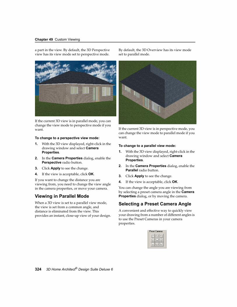
Chapter 49 Custom Viewing
324 3D Home Architect® Design Suite Deluxe 6
a part in the view. By default, the 3D Perspective view has its view mode set to perspective mode.
If the current 3D view is in parallel mode, you can change the view mode to perspective mode if you want.
To change to a perspective view mode:1. With the 3D view displayed, right-click in the
drawing window and select Camera Properties.
2. In the Camera Properties dialog, enable the Perspective radio button.
3. Click Apply to see the change.
4. If the view is acceptable, click OK.
If you want to change the distance you are viewing from, you need to change the view angle in the camera properties, or move your camera.
Viewing in Parallel ModeWhen a 3D view is set to a parallel view mode, the view is set from a common angle, and distance is eliminated from the view. This provides an instant, close-up view of your design.
By default, the 3D Overview has its view mode set to parallel mode.
If the current 3D view is in perspective mode, you can change the view mode to parallel mode if you want.
To change to a parallel view mode:1. With the 3D view displayed, right-click in the
drawing window and select Camera Properties.
2. In the Camera Properties dialog, enable the Parallel radio button.
3. Click Apply to see the change.
4. If the view is acceptable, click OK.
You can change the angle you are viewing from by selecting a preset camera angle in the Camera Properties dialog, or by moving the camera.
Selecting a Preset Camera AngleA convenient and effective way to quickly view your drawing from a number of different angles is to use the Preset Cameras in your camera properties.

Changing the Viewing Field Angle
User’s Guide 325
49
The nine preset camera angles show your drawing:
• looking down at an angle from above the four corners
• looking straight on from the four sides• looking straight down from directly above
(90°)
To select a preset Camera angle:1. With the 3D view displayed, right-click in the
drawing window and select Camera Properties.
2. In the Camera Properties dialog, click on one of the buttons in the Preset Cameras area.
3. Click Apply to see the change.
4. If the view is acceptable, click OK.
Note: You can change your viewing angle to any angle you want by moving the camera or using one of the dynamic navigation tools.
Changing the Viewing Field AngleThe viewing field can only be changed in the 3D Perspective view, or views with their view mode set to Perspective.
The viewing field refers to your field of vision. It works like a camera lens: higher values produce a wide-angle view; lower values produce a close-up view.
Sometimes changing the viewing field angle makes it seem like you are zooming in or out. This is because for wide-angle views, the program needs to shrink the image to provide enough screen space to contain the view. Conversely, the
program enlarges the image to fill the screen at smaller view angles, creating a close-up view.
Interior with 45º View Angle
Interior with 120º View Angle
To change the viewing field angle:1. With the 3D view displayed, right-click in the
drawing window and select Camera Properties.
2. In the Camera Properties dialog, type the desired angle in the View Angle edit box, or use the slider to increase or decrease the angle.
3. Click Apply to see the change.
4. If the view is acceptable, click OK.

Chapter 49 Custom Viewing
326 3D Home Architect® Design Suite Deluxe 6
Walking Around in 3D ViewWhen you are in a 3D view, you can use the Walk Around tool to walk around your model, or even go right inside it. You can walk forward, backward, left or right.
To walk around in 3D view:1. Select View > Zoom and Navigate >
Walk Around, or right-click in the drawing area and select Walk Around, or click the Walk Around button on the Zoom and Navigate toolbar.
2. Click and drag in the direction you want to move.
• To move forward, click and drag upward.
• To move backward, click and drag downward.
• To walk left or right, click and drag left or right.
If you click and drag up to the left, your path of motion will curve upward to the left, and so forth.
Flying Around Your 3D ModelIn a 3D view, the Fly Around tool revolves the camera around the target.
To fly around your model:1. Select View > Zoom and Navigate >
Fly Around, or right-click in the drawing area and select Fly Around, or click the Fly Around button on the Zoom and Navigate toolbar.
2. Use your mouse button to orbit the camera. Your options are described below.
• Click and hold the mouse button to slowly rotate the camera around the target on a level plane.
• Drag toward the top of the screen to make your model tilt downward like a boat coming off a wave.
• Drag toward the bottom of the screen to make your model tilt up like a boat riding onto a wave.
• Drag to the right to rotate the model in a clockwise direction.
• Drag to the left to rotate the model in a counterclockwise direction.
Note: Model direction is the opposite of camera direction. For example, if the model appears to be moving clockwise, the camera is actually moving counterclockwise.
Sliding in a 3D ViewIn a 3D view, the Slide tool moves both the camera and target at the same time.
To slide in a 3D view:1. Select View > Zoom and Navigate >
Slide, or right-click in the drawing area and select Slide, or click the Slide button on the Zoom and Navigate toolbar.
2. Once Slide is selected, you can do the following:
• Drag right to move your model view to the left.
• Drag left to move your model view to the right.
• Drag up (toward the top of the screen) to move your model view down (toward the bottom of the screen).
• Drag down to move your model view up.
Note: Model direction is the opposite of camera and target direction. For example, if the model appears to be moving to the right, the camera and target are actually moving to the left.
Spinning the View Using the Look Around Tool In a 3D view, the Look Around tool revolves the target around the camera.
To spin the view:1. Select View > Zoom and Navigate >
Look Around, or right-click in the drawing area and select Look Around, or click the Look Around button on the Zoom and Navigate toolbar.

Resetting the Camera in a 3D View
User’s Guide 327
49
2. Once Look Around is selected, you can do the following (presuming that your target is located inside or near the model):
• Drag right to move the target in a counterclockwise direction. Your model orbits around you in a clockwise direction.
• Drag left to move the target in a clockwise direction. Your model orbits around you in a counterclockwise direction.
• Drag up to lower the height and shorten the distance of the target. Your view becomes high-angle, and your model moves toward the top of the screen.
• Drag down to raise the height and lengthen the distance of the target. Your view becomes low-angle, and your model moves toward the bottom of the screen.
Note: Be careful when using the Look Around tool. It is very easy to lose sight of your model since the camera's "eye" is fixed in one direction only. It does not move to follow the orbiting target. Therefore, your field of vision is limited, and your model can quickly get above, below or behind you.
Resetting the Camera in a 3D ViewIf you have moved your camera, either by dragging it in 2D plan view or using a navigation tool like Walk Around or Slide, you can use the Reset Camera tool to move the camera back into its original position. Note that this tool is only available when the current view is a 3D view.
To reset the camera to its original position:1. Select View > Zoom and Navigate >
Reset Camera, or click the Reset Camera button on the Zoom and Navigate toolbar.
Selecting a Background for 3D ViewsBy default, a sky image is displayed behind your model when you are in a 3D view. You can select a different image to display, including custom bitmaps that you have imported, or switch to a night scene.
To select a background for the view:1. Select Settings > Background
Settings, or click the Background Settings button on the Settings toolbar.
2. In the Background Settings dialog, select either the Day Scene or Night Scene radio button. You would want to switch to a night scene if you are doing a nighttime 3DTrueView™ rendering of your model.
3. Click on the current preview to access the Materials dialog.

Chapter 49 Custom Viewing
328 3D Home Architect® Design Suite Deluxe 6
4. In the Materials dialog, select a background from the Materials list. To add a material to the list (if you have your own bitmap, for example), see Customizing the Materials Library on page 348.
5. Click OK in the Materials dialog.
6. Click OK in the Background Settings dialog.
Viewing ElevationsElevations are 2D views that show a particular side of your house (front, rear, left or right) as if you were looking at it face on. While in an elevation view you can zoom in and out as well as change the display type.
Sample Elevation
To view an elevation:1. Select View > Elevation View, or click the
Elevation View button on the Advanced View Control toolbar.
2. From the flyout, select the elevation you want to view (Front, Back, Right or Left).
Tip: If you have your elevation marks turned on in your 2D plan view, you can switch to an elevation view by selecting an elevation mark, right-clicking it, then selecting View Elevation.
Turning Elevation Marks On and OffYou can use the Elevation Marks On/Off tool to display elevation marks in your 2D plan view. An elevation mark contains the label given to the elevation in the elevation’s properties, as well as a
target arrow that identifies the view direction of the elevation.
Back Elevation Mark
By default, four marks are displayed, one for each of the default elevations on the Elevation View menu. If you have created a custom elevation, a mark is displayed for that elevation as well.
To turn elevation marks on or off:• Select View > Viewing Aids > Elevation
Marks On/Off, or• Click the Viewing Aids button on the Basic
View Control or Advanced View Control toolbar and select Elevation Marks On/Off
The marks are located at the extents of your drawing, so you may need to zoom out to see them.
If you select and right-click an elevation mark, you can access a number of editing tools such as Properties, Move and Move Target. Selecting View Elevation displays the elevation associated with that mark.
Moving Elevation MarksBy default, elevation marks are centered with your model, which means the model is centered on the screen when you view the resulting elevation view. If you move an elevation mark in your 2D plan view, the model may be moved left or right when you display the elevation view. Moving a mark closer to or farther away from the model has no effect on the resulting elevation view.
To move an elevation mark:1. Select the elevation mark in 2D plan view.
2. Hover your pointer over the mark’s blue grab handle to display the Move cursor. Or, right-click in the drawing area and select Move.

Changing the Target of an Elevation
User’s Guide 329
49
3. Click and drag the mark to move it where you want it.
4. Right-click and select View Elevation to see the resulting elevation.
Changing the Target of an ElevationBy default, elevation marks point straight at your model. The result is a completely face-on view when you display the resulting elevation view. If you rotate an elevation mark, you change the target of the elevation. This focuses the view on a different part of your design when you display the elevation view.
To change the target of an elevation:1. Make sure your elevation marks are turned
on.
2. In 2D plan view, select the mark whose target you want to change.
3. Right-click and select Move Target.4. Click and drag to rotate the mark so it is
pointing in a different direction.
5. Right-click and select View Elevation to see the result.
Editing Elevation PropertiesYou can edit the name of an elevation as it appears on the Elevation View menu, as well as edit the name and text style of an elevation mark.
To edit elevation properties:1. If the elevation view is currently displayed,
right-click and select Elevation Properties. If you are currently in 2D plan view, select the elevation mark, then right-click and select Properties.
2. To edit the name of the elevation as it appears on the Elevation View menu, edit the name in the Name edit box.
3. To edit the text that appears on the elevation mark, edit the text in the Mark Text edit box.
4. To apply a different text style to the elevation mark, click the Text Style button and make a selection from the Text Styles dialog. You can also edit the current text style if you want.
5. Click OK.
Deleting an ElevationYou can delete an elevation from the Elevation View menu by deleting its corresponding elevation mark in 2D plan view.
To delete an elevation:1. Make sure your elevation marks are turned
on.
2. In 2D plan view, select the mark to delete.
3. Press the Delete key on your keyboard, or right-click and select Delete.
Creating a Custom ElevationYou can create a custom elevation by inserting an elevation mark in your 2D plan view. Once you’ve inserted the mark, which represents your viewpoint, you can rotate it using your mouse to define the view direction.
To create a custom elevation:1. Make sure you are in 2D plan view.
2. Turn your elevation marks on. This is not necessary, but we recommend it so that you can see where other elevation marks are located. The default elevation marks are located at the extents of the terrain, so you may need to zoom out to see them.
3. Select View > Elevation View > Create New Elevation, or click the Elevation View button on the Advanced View Control toolbar and select Create New Elevation. An elevation mark is attached to your cursor, ready to be inserted.

Chapter 49 Custom Viewing
330 3D Home Architect® Design Suite Deluxe 6
4. Click to insert the new elevation mark. This represents your viewpoint, so naturally you would select a point in front of the model side you want to look at in your elevation.
5. Move your cursor to rotate the arrow on the elevation mark and define the view direction. Once it is pointing in the desired direction (usually towards your model), click to finish.
Once you’ve positioned the elevation mark, the resulting elevation is instantly displayed. It is also added to the Elevation View menu and toolbar flyout for easy access. (By default, the first view you create is called Elevation1.)
Tip: You can change the name of the elevation as well as edit the elevation mark properties by editing the Elevation Properties.
Creating a Section ViewYou can cut through any portion of your model to create a section view. Section views are a great way to see the interior features of your model that you are not able to see from the outside.
Sample Section
To create a section view, you draw a section line through your model in 2D plan view, then click to define the view direction and depth.
To create a section view:1. Make sure you are in 2D plan view.
2. Select View > Section View > Create New Section, or click the Section View button on the Advanced View Control toolbar and select Create New Section.
3. Select two points to draw a line that cuts through your model. This is the line you will be viewing from.
4. Move your cursor in the direction you want to view. The more you move away from the section line, the deeper your view becomes. Once the bounding box is the desired distance and direction from the section line, click to finish.
Once you’ve defined the section mark, the resulting section view is instantly displayed. It is also added to the Section View menu and toolbar flyouts for easy access. (By default, the first view you create is called Section1.)
Viewing Section Views If you have created section views, you can display them at any time using the Section View menu or toolbar.
To view a section view:1. Select View > Section View, or click
the Section View button on the Advanced View Control toolbar.
2. From the flyout, select the section you want to view.
Tip: If you have your section marks turned on in your 2D plan view, you can switch to a section view by selecting a section mark, right-clicking it, then selecting View Section.

Turning Section Marks On and Off
User’s Guide 331
49
Turning Section Marks On and OffWhen you create a section, a section mark is displayed in the 2D plan view. The section mark contains markers at each end of the section line which indicate the direction of the section view. You can turn section marks on and off using the Section Marks On/Off tool.
To turn section marks on or off:• Select View > Viewing Aids > Section
Marks On/Off, or• Click the Viewing Aids button on the Basic
View Control or Advanced View Control toolbar and select Section Marks On/Off
Editing a Section ViewYou can edit a section view by moving the section mark associated with the section view, or by stretching the bounding box attached to the section line. By moving a section mark you are changing your viewpoint. By stretching the bounding box, you are changing the depth of the view.
To change your viewpoint by moving the section mark:1. In 2D plan view, make sure your section
marks are turned on.
2. Click on the section mark.
3. Hover your pointer over the blue grab handle on the section line to display the Move cursor. Or, right-click in the drawing area and select Move.
4. Click and drag the mark to move it where you want it.
5. Right-click and select View Section to see the result.
To change the depth of the section view:1. In 2D plan view, make sure your section
marks are turned on.
2. Click on the section mark.
3. Hover your pointer over the blue grab handle on the bounding box line to
display the Stretch cursor. Or, right-click in the drawing area and select Stretch.
4. Click and drag to make the bounding box smaller or bigger. The bigger the box, the deeper the view.
5. Right-click and select View Section to see the result.
Editing Section PropertiesYou can edit the name of a section as it appears on the Section View menu, as well as edit the name and text style of a section mark.
To edit section properties:1. If the section view is currently displayed,
right-click and select Section Properties. If you are currently in 2D plan view, select the section mark, then right-click and select Properties.
2. To edit the name of the section as it appears on the Section View menu, edit the name in the Name edit box.
3. To edit the text that appears on the section mark, edit the text in the Mark Text edit box.
4. To apply a different text style to the section mark, click the Text Style button and make a selection from the Text Styles dialog. You can also edit the current text style if you want.
5. Click OK.
Deleting a Section ViewYou can delete a section from the Section View menu by deleting its corresponding section mark in 2D plan view.

Chapter 49 Custom Viewing
332 3D Home Architect® Design Suite Deluxe 6
To delete a section:1. Make sure your section marks are turned on.
2. In 2D plan view, select the mark to delete.
3. Press the Delete key on your keyboard, or right-click and select Delete.

333
Chapter
3D Home Architect® Design Suite’s Catalog Manager lets you add, edit and delete elements to suit your needs. You can also create new, custom catalogs that contain a specific selection of elements. You can open any catalog you want during a work session to gain access to the elements you want.
Another great feature is Save Element to Catalog, which lets you save an element that you have edited in your drawing to the current catalog.
Catalogs & Elements
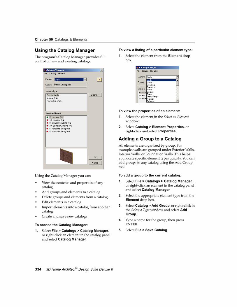
Chapter 50 Catalogs & Elements
334 3D Home Architect® Design Suite Deluxe 6
Using the Catalog ManagerThe program’s Catalog Manager provides full control of new and existing catalogs.
Using the Catalog Manager you can:
• View the contents and properties of any catalog
• Add groups and elements to a catalog• Delete groups and elements from a catalog• Edit elements in a catalog• Import elements into a catalog from another
catalog• Create and save new catalogs
To access the Catalog Manager:1. Select File > Catalogs > Catalog Manager,
or right-click an element in the catalog panel and select Catalog Manager.
To view a listing of a particular element type:1. Select the element from the Element drop
box.
To view the properties of an element:1. Select the element in the Select an Element
window.
2. Select Catalog > Element Properties, or right-click and select Properties.
Adding a Group to a CatalogAll elements are organized by group. For example, walls are grouped under Exterior Walls, Interior Walls, or Foundation Walls. This helps you locate specific element types quickly. You can add groups to any catalog using the Add Group tool.
To add a group to the current catalog:1. Select File > Catalogs > Catalog Manager,
or right-click an element in the catalog panel and select Catalog Manager.
2. Select the appropriate element type from the Element drop box.
3. Select Catalog > Add Group, or right-click in the Select a Type window and select Add Group.
4. Type a name for the group, then press ENTER.
5. Select File > Save Catalog.

Renaming a Group in a Catalog
User’s Guide 335
50
Renaming a Group in a CatalogYou can change the name of any group in a catalog using the Rename Group tool.
To rename a group:1. Select File > Catalogs > Catalog Manager,
or right-click an element in the catalog panel and select Catalog Manager.
2. Select the appropriate element type from the Element drop box.
3. In the Select a Type window, select the group you want to rename.
4. Select Catalog > Rename Group, or right-click and select Rename Group.
5. Type the new name and press ENTER.
6. Select File > Save Catalog.
Deleting a Group in a CatalogYou can delete a group in a catalog provided it contains no elements.
To delete a group in a catalog:1. Select File > Catalogs > Catalog Manager,
or right-click an element in the catalog panel and select Catalog Manager.
2. Select the appropriate element type from the Element drop box.
3. In the Select a Type window, select the group you want to delete. Note that the group can only be deleted if it contains no elements.
4. Select Catalog > Delete Group, or right-click and select Delete Group.
5. Select File > Save Catalog.
Adding and Editing Elements in a CatalogEvery element has a number of different properties that determine its size, geometry and appearance. You can edit these properties to suit your needs. If you want you can create a new element instead of editing an existing one.
Note: You can’t edit elements in the catalog panel. You need to use the Catalog Manager.
To edit an element in a catalog:1. Select File > Catalogs > Catalog Manager,
or right-click an element in the catalog panel and select Catalog Manager.
2. Select the appropriate element type from the Element drop box.
3. In the Select a Type window, select the group containing the element you want to edit.
4. In the Select an Element window, select the element to edit.
5. Select Catalog > Element Properties, or right-click and select Properties.
6. Edit the properties as desired. See Working with Property Pages on page 339 for more information.
7. Click OK to return to the Catalog Manager.8. Select File > Save Catalog.
Note: Editing elements in a catalog has no effect on elements already inserted in your drawing. It only affects future insertions of the element.
To add a new element to a catalog:1. Select File > Catalogs > Catalog Manager,
or right-click an element in the catalog panel and select Catalog Manager.
2. Select the appropriate element type from the Element drop box.
3. In the Select a Type window, select the group you want to add the element to.
4. Select Catalog > Add Element.Elements like furniture, appliances and accessories can be defined based on a set of general parameters, or by importing a 3D

Chapter 50 Catalogs & Elements
336 3D Home Architect® Design Suite Deluxe 6
Studio file. If this is the case, you will see a dialog similar to the following:
To define the element by specifying size properties, select the Use a Parametric Template radio button, select the specific element type you want to create (chair, table, etc.), then click OK.
To import a 3D Studio file, select the Import geometry from file radio button, click OK, then select the desired 3D Studio file. Some elements, like electronics, will prompt you directly for a 3D Studio file because they do not have a parametric template. For more information, see Importing 3D Studio Files on page 336.
5. Define the element's properties. (See Working with Property Pages on page 339.)
Note that if the Auto Name check box is enabled, the element will be automatically named for you. For example, if you are creat-ing a wall and select Masonry for the wall type, and specify a width of 6”, the name automatically becomes 6” Masonry Wall. For more information about automatic name gen-eration, see Using Automatic Name Genera-tion on page 339.)
If you want to give the element a different name, disable the Auto Name check box and type the desired name in the Name edit box.
6. Click OK. The element is added to the catalog.
7. Select File > Save Catalog.
Saving Edited Elements in Your Drawing to a CatalogIf you have edited the properties of an inserted element, you can save that element (and its custom properties) to the current catalog.
To add an edited element from your drawing into the current catalog:1. Select File > Catalogs > Save
Element to Catalog. Your pointer changes to a catalog cursor.
2. Select the element in your drawing.
3. Click Yes to save the element. The element is added to the current catalog.
Importing 3D Studio FilesMany sites on the Internet offer free downloading of elements in 3D Studio (*.3ds) format. You can easily convert these files for use in 3D Home Architect® Design Suite.
To import a 3D Studio file:1. Select File > Catalogs > Catalog Manager,
or right-click an element in the catalog panel and select Catalog Manager.
2. Select the appropriate element type from the Element drop box (e.g. Furniture).
3. In the Select a Type window, select the group you want to add the element to.

Importing 3D Studio Files
User’s Guide 337
50
4. Select Catalog > Add Element. In the Define Element dialog, select the Import geometry from file radio button.
5. Click OK.
6. In the Open dialog, select the 3D Studio file, then click Open.
Since 3D Home Architect® Design Suite can only import 3D Studio files, the only selection in the Create Components From drop box is Materials, since 3DS objects are essentially an assembly of materials.
7. By default, the imported object’s materials will be stored in a new group in your materials library. If you want to store them in
a specific group, click Select, then select the desired group.
8. Click OK in the Material Group(s) dialog.
9. When you import a 3D Studio block, there is usually no way of knowing what units the designer intended for the block. In the Block Import Options dialog, select the unit of measure in the Convert File From drop box that will result in a logical Resultant Width, Depth and Height. Selecting Custom lets you specify a custom scale in the Custom Scale edit box.
The scale is the multiplication factor of the units used for objects in the block. For example, if you're converting a file that you assume was created in feet and inches, the scale is 25.4.
10. Once logical dimensions are displayed, click OK in the Block Import Options dialog.
11. In the properties dialog, enter a name for the element in the Name edit box.
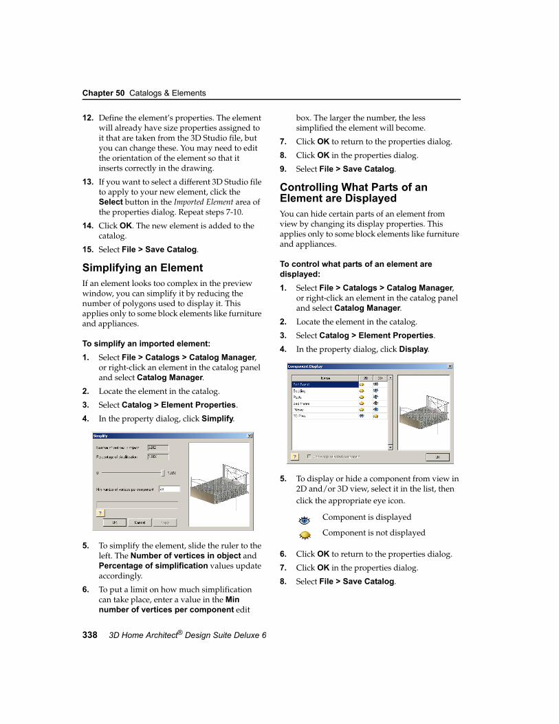
Chapter 50 Catalogs & Elements
338 3D Home Architect® Design Suite Deluxe 6
12. Define the element’s properties. The element will already have size properties assigned to it that are taken from the 3D Studio file, but you can change these. You may need to edit the orientation of the element so that it inserts correctly in the drawing.
13. If you want to select a different 3D Studio file to apply to your new element, click the Select button in the Imported Element area of the properties dialog. Repeat steps 7-10.
14. Click OK. The new element is added to the catalog.
15. Select File > Save Catalog.
Simplifying an ElementIf an element looks too complex in the preview window, you can simplify it by reducing the number of polygons used to display it. This applies only to some block elements like furniture and appliances.
To simplify an imported element:1. Select File > Catalogs > Catalog Manager,
or right-click an element in the catalog panel and select Catalog Manager.
2. Locate the element in the catalog.
3. Select Catalog > Element Properties.
4. In the property dialog, click Simplify.
5. To simplify the element, slide the ruler to the left. The Number of vertices in object and Percentage of simplification values update accordingly.
6. To put a limit on how much simplification can take place, enter a value in the Min number of vertices per component edit
box. The larger the number, the less simplified the element will become.
7. Click OK to return to the properties dialog.
8. Click OK in the properties dialog.
9. Select File > Save Catalog.
Controlling What Parts of an Element are DisplayedYou can hide certain parts of an element from view by changing its display properties. This applies only to some block elements like furniture and appliances.
To control what parts of an element are displayed:1. Select File > Catalogs > Catalog Manager,
or right-click an element in the catalog panel and select Catalog Manager.
2. Locate the element in the catalog.
3. Select Catalog > Element Properties.
4. In the property dialog, click Display.
5. To display or hide a component from view in 2D and/or 3D view, select it in the list, then click the appropriate eye icon.
6. Click OK to return to the properties dialog.
7. Click OK in the properties dialog.
8. Select File > Save Catalog.
Component is displayed
Component is not displayed

Working with Property Pages
User’s Guide 339
50
Working with Property PagesWhen you access an element’s property pages, a multi-tabbed dialog is displayed. The tabs and properties vary depending on the element. The most common property pages are Basic, Appearance, Quantity and Behavior. The name, notes and hyperlinks properties are common to all property pages.
Sample Properties Dialog
A preview of the element is shown in the preview window. By default, the image is displayed in a 3D rendered view. You can switch between 3D and 2D as well as select a different display mode by right-clicking in the preview window and making a selection from the menu.
When the image is in a 3D view, you can rotate it around by clicking and dragging with your mouse.
Using Automatic Name GenerationNames of elements are based on pre-defined formulas. The name 8" Concrete Wall is made up of three variables:
Each variable is separated by a space. These variables and spaces are defined in the name's formula.
If you add or change an element, and select Auto Name, the element's name updates automatically in the catalog. For example, if you create a concrete wall, and define a width of 10", the name automatically becomes 10" Concrete Wall.
Automatic name generation:
• Saves typing a name every time you add or edit an element
• Ensures consistency in catalogs • Prevents duplicate entries if you forget to
change a nameTo use automatic name generation when adding or editing an element, enable the Auto Name check box next to the Name edit box in the element’s properties dialog.
Note: If Auto Name is not selected, you can type any name you want in the Name edit box.
Editing the Name Generation FormulaWhen you add or edit a catalog element, you can modify the formula used to generate the element's name if you are using automatic name generation. Formulas are made up of variables (like Element Class and Element Type) and separators (spaces, symbols or characters).
Editing an element’s name generation formula sets the formula for any new elements you create of that type. For example, if you edit the name generation formula for an 8” Brick Wall, any new walls you add to the catalog will use the new formula if you use automatic name generation.
8” Concrete WallWidth Type Element

Chapter 50 Catalogs & Elements
340 3D Home Architect® Design Suite Deluxe 6
To modify the formula used for an element's automatic name generation:1. Select File > Catalogs > Catalog Manager,
or right-click an element in the catalog panel and select Catalog Manager.
2. Select the appropriate element type from the Element drop box.
3. Select the element to edit.
4. Select Catalog > Element Properties, or right-click and select Properties.
5. Click the Options button to the right of the Auto Name check box. The Automatic Name Generation dialog for that element type is displayed. The right pane (titled Used Variables and Separators) displays the current formula.
6. To remove a component from the formula, select it and click Remove.
7. To add a component to the formula, select the desired variable or separator in the Available Variables or Available Separators window and click Add.
8. To move a component in the formula, select the component and click Move Up or Move Down.
9. When you have finished modifying the formula, click OK to close the Automatic Name Generation dialog.
10. Click OK to close the element's properties dialog.
11. In the Catalog Manager, select File > Save Catalog.
Basic PageMost elements have a Basic property page, although the properties on this page will vary according to the element type. Generally there is a Type section, where you can select the specific element type, as well as a Properties section, where you can specify the dimensions of the element.
Sample Basic Page
Note: You can find detailed descriptions of size properties for specific element types in their respective chapters.
Changing an Element’s OrientationSymbol elements, such as furniture and light fixtures, are oriented in a logical fashion when you insert them in your drawing. For example, tables are inserted in a flat, upright position on the floor, and electrical outlets are inserted in a vertical position on the face of walls. You can edit the orientation of most symbol elements. For example, you may want to flip an air register so that you can insert it on the ceiling in your basement.

Appearance Page
User’s Guide 341
50
To change an element’s orientation:1. On the Basic property page, click the
appropriate arrow keys in the Orientation area to rotate the element.
(Y, Z) axes: Rotates the element front to back, and vice versa.
(X, Z) axes: Rotates the element towards its left or right side in 3D.
(X, Y) axes: Rotates the element left or right in 2D plan view.
Appearance PageThe Appearance properties page is common to most elements. It provides control over the materials applied to elements, which come into play when you view your model in Rendered or Patterned mode.
A material can be a texture, such as brick, or a color. This is what you see in Rendered mode. Materials also have a pattern assigned to them, which is what you see when you view in Patterned mode.
The contents of the Components window varies depending on the element. It contains a listing of the individual components that make up the element, so you can apply a different material to each component.
Sample Appearance Page
To change an element’s material:1. In the Components pane, select the component
whose material you want to change.
2. In the Material area, click the Select button.
3. In the Materials dialog, select the group containing the desired material. If you want to choose a solid color, select the Paint group.
4. Select the material you want to use. The swatches in the preview windows update automatically. If you want to edit the material, click on one of the swatches to access the Edit Materials dialog. For information about editing materials, see Editing Material Properties on page 349.
5. Click OK to return to the Appearance page.
6. If you want to rotate the material on the element, enter an angle in the Rotation edit box, or use the arrows to scroll through a list of angles. This rotates the material in a clockwise direction.
7. To shift the material on the element (left, right, up or down), use the Position arrows.
8. Select another component in the Components pane and select a material for that component.

Chapter 50 Catalogs & Elements
342 3D Home Architect® Design Suite Deluxe 6
9. When all your materials are defined, click OK.
Quantity PageThe Quantity properties page is common to most elements. It contains information that helps identify the element as a material, such as the manufacturer and price. Some of the information on this page is used in the project estimate.
Sample Quantity Page
Manuf: The Manufacturer of the product.
Supplier: The company or store who will be supplying the product.
Price: The unit price of the product.
Division: A construction division identification. In North America, CSI divisions are used.
Part No.: Part Number. A series of numbers that identifies the product.
Alt Code: Alternate Code. An extra identification code that is used to link an element in the program’s catalog to the databases of other applications, such as Timberline.
Behavior PageThe Behavior property page is available for symbol elements like cabinets, furniture and lights.
Sample Behavior Page
Usually this page contains a Distance above current location or terrain option which lets you control the height at which the element is inserted relative to the floor or terrain. The value entered is the distance from the floor or terrain to the insertion point of the element. (For most elements except windows and wall openings, the insertion point is at the bottom of the element.)
Some elements have a defined Insertion Point, which is the point on the element that is attached to the cursor when you are inserting the element. Some elements also have a defined Snap Edge, which determines which edge of the element will snap to the wall if you position it near a wall.
To edit an element’s insertion height:1. Edit the value in the Distance above current
location or terrain edit box.
To edit an element’s insertion point:1. Edit the values in the X Axis, Y Axis and Z
Axis edit boxes, or use the sliders beside these edit boxes.

Adding Notes to an Element’s Properties
User’s Guide 343
50
An X value moves the insertion point left or right. A Y value moves the insertion point forwards or backwards. A Z value moves the insertion point up or down on the element.
To edit an element’s snap edge:1. Click on the desired snap edge graphic in the
Snap Edge area.
Adding Notes to an Element’s PropertiesThe Notes function in the properties dialog lets you enter a note about the element. This additional information can be anything you want.
To add a note to an element’s properties:
1. Select File > Catalogs > Catalog Manager, or right-click an element in the catalog panel and select Catalog Manager.
2. Select the appropriate element type from the Element drop box.
3. Select the element to edit.
4. Select Catalog > Element Properties, or right-click and select Properties.
5. In the bottom left corner of the dialog, click the Add Notes button.
6. Enter your note in the Notes dialog.
7. Click OK.
Adding Hyperlinks to an Element’s PropertiesThe Hyperlinks function in the properties dialog lets you create a link to an external file (e.g. Word document) or Web address.
To add a hyperlink to an element’s properties:1. Select File > Catalogs > Catalog Manager,
or right-click an element in the catalog panel and select Catalog Manager.
2. Select the appropriate element type from the Element drop box.
3. Select the element to edit.
4. Select Catalog > Element Properties, or right-click and select Properties.
5. In the bottom left corner of the dialog, click the Add Hyperlinks button.
6. In the Hyperlinks dialog, specify a name for the hyperlink in the Name edit box (e.g. Broderbund Web Site).
7. In the Link to edit box, type the web address (e.g. http://www.broderbund.com) or path to the file you are linking to. If you are linking to a file, you can click Browse to search through the directories on your computer. Once you’ve located the file in the Open dialog, click Open. The path to the file is automatically displayed in the Link to edit box.
8. Click Add to add the link to the hyperlink window.
9. To view the link, select it in the hyperlink window, then click Go to.
10. To delete a hyperlink, select it in the hyperlink window, then click Delete.
11. Click OK.

Chapter 50 Catalogs & Elements
344 3D Home Architect® Design Suite Deluxe 6
Note: You can create a link to another
Broderbund® Home Design (*.bld) file. However, if that file uses the same catalog as the current drawing, you cannot access the catalog in the linked file.
Creating a New CatalogIf you plan to edit or add elements in the Master Catalog, you may want to create a new catalog instead of editing the existing one. That way, the custom elements you create are distinguishable from the defaults and are stored in one place. When you create a new catalog, you specify a name and where you want to store the catalog.
When you close the Catalog Manager, the new catalog will become the current catalog in the catalog panel.
To create a new catalog:1. Select File > Catalogs > Catalog Manager,
or right-click an element in the Catalog panel and select Catalog Manager.
2. Select File > New Catalog.
3. In the Create a new catalog dialog, type a name (without extension) in the File Name box.
4. Click the Browse button next to the Location edit box and select the directory where you want to store the new catalog. The default is the program's
Catalogs directory, which is where you should store all catalogs.
5. From the Type drop box, select the unit of measure you would like to use for elements in the catalog.
6. From the Precision drop box, select the level of precision you would like to use for measurements. For example, selecting #’-# #/16” sets the level of precision to 1/16th of an inch when working in feet and inches.
7. In the Name edit box, type your name.
8. In the Company edit box, type the name of your company, if applicable.
9. Click OK. A new, blank catalog is created.
10. Select File > Save Catalog.
11. You can now add groups and elements to the catalog, or import elements from another catalog (see Importing Elements into Catalogs on page 345). Remember to save the catalog after you make changes to it.

Creating a Copy of a Catalog
User’s Guide 345
50
Creating a Copy of a CatalogYou can save a catalog under a different name, which essentially creates a copy of it.
To create a copy of a catalog under a different name:1. Select File > Catalogs > Catalog Manager,
or right-click an element in the catalog panel and select Catalog Manager.
2. Make sure the catalog you want to save is the current catalog.
3. Select File > Save Catalog As.
4. In the File name edit box, type the name you want to save under (without extension).
5. Click Save.
Note: The newly saved catalog becomes the current catalog.
Importing Elements into CatalogsUsing the Catalog Manager you can import elements from another catalog into the current catalog. This feature is often used when you are creating new catalogs.
Note: If you want to import a 3D Studio file, see Importing 3D Studio Files on page 336.
To import elements into a catalog:1. Select File > Catalogs > Catalog Manager,
or right-click an element in the catalog panel and select Catalog Manager.
2. Make sure the catalog you want to import elements into is the currently open catalog.
3. From the Element drop box, select the appropriate element type.
4. Click Expand to expand the Catalog Manager dialog.
5. On the right side of the dialog, click the Browse button, then select the catalog you want to import elements from.
6. In the right-hand window, select an element to import, then click Import Item. If you want to import all elements listed, just click Import All. The element is imported into the current catalog. Note that the group that the element belongs to is also imported into the current catalog.
7. When you are done importing elements, click Collapse to return to the regular view in the Catalog Manager.
8. Select File > Save Catalog.

Chapter 50 Catalogs & Elements
346 3D Home Architect® Design Suite Deluxe 6
Deleting Elements from a CatalogYou can delete any element from a catalog.
To delete an element from a catalog:1. Select File > Catalogs > Catalog Manager,
or right-click an element in the catalog panel and select Catalog Manager.
2. Select the appropriate element type from the Element drop box.
3. Select the element you want to delete.
4. Select Catalog > Delete Element, or right-click and select Delete Element.
5. Select File > Save Catalog.
Opening a CatalogYou can use the Open Catalog tool to open any catalog and make it the current catalog in the catalog panel. The Open Catalog tool is also available in the Catalog Manager.
To open a catalog for display in the Catalog panel:1. Select File > Catalogs > Open Catalog.
2. In the Open dialog, locate the catalog you want to open.
3. Click Open. The catalog you opened becomes the active catalog. Note that when you open a catalog, only one element type is displayed. The type displayed depends on the last Insert tool selected.
To open a catalog in the Catalog Manager:1. Select File > Catalogs > Catalog Manager,
or right-click an element in the catalog panel and select Catalog Manager.
2. Select File > Open Catalog.
3. In the Open dialog, locate the catalog you want to open.
4. Click Open. The catalog you opened becomes the active catalog in the Catalog Manager.
5. Click OK. The catalog is now the current catalog in the catalog panel.
Closing a CatalogYou can use the Close Catalog tool to close the current catalog in the catalog panel or the Catalog Manager dialog. Note that this leaves the catalog window blank until you open another catalog.
To close the catalog in the catalog panel:1. Select File > Catalogs > Close Catalog.
To close a catalog in the Catalog Manager:1. Select File > Close Catalog.
Viewing Catalog PropertiesYou can view the properties of the current catalog (file name, location, etc.) using the Catalog Properties tool.
To view the properties of the catalog currently in the catalog panel:1. Select File > Catalogs > Catalog Properties.
To view catalog properties within the catalog Manager:1. Select File > Catalog Properties.

347
Chapter
Every element has a material assigned to it in the element's property pages. Materials determine what textures, colors and patterns are used to display elements in 3D view. You can edit and create materials on the fly.
All materials are stored in a materials library, called materials.mlb. You can create new material libraries containing a specific selection of materials, and load those custom libraries in other projects.
This chapter tells you how to customize materials and work with material libraries.
If you want to edit the material, color or pattern of an inserted element, see Changing an Element’s Material or Color on page 259.
Materials, Colors & Patterns

Chapter 51 Materials, Colors & Patterns
348 3D Home Architect® Design Suite Deluxe 6
Things You Should Know About Editing MaterialsWhen you add or edit a material through the Catalog Manager, the custom material is saved with the catalog, and is only available when editing elements in the catalog. If you add or edit a material when editing an element that has been inserted in your drawing, however, the customized material is only available in the current project when editing the properties of inserted elements. The materials library in the catalog remains unchanged. This is because the materials library in the catalog is separate from the materials library in the current drawing.
The reason that there is a project-specific materials library is so that any materials used in your project are always saved with the project, making it possible to share your project with others and always maintain your customized materials.
If you want materials that you have customized in your catalog to be available in your project-specific materials library, or vice versa, you can use the Transfer tool to save the custom materials to the external materials library file (materials.mlb), then import the custom materials from the library file into the other materials library.
Customizing the Materials LibraryThe materials library contains a vast array of materials that you can apply to elements. Even so, you may find that you want to customize it at some point in time.
In the materials library, materials are listed in groups (Concrete, Brick, Wood, etc.) so you can organize and find them easily. You can add, rename and delete groups as needed.
You can add new materials to the library, as well as edit and delete existing materials.
If you customize the catalog materials library (through the Catalog Manager), your change is saved with the catalog.
If you customize the project-specific materials library (by editing an inserted element), your change is saved in the current project only.
To access the catalog materials library:1. Select File > Catalogs > Catalog Manager,
or right-click an element in the catalog panel and select Catalog Manager.
2. In the Catalog Manager, select Libraries > Materials. The Materials dialog appears.
To access the project-specific materials library:1. Select an element in your drawing.
2. Right-click and select Properties.
3. In the properties dialog, select the Appearance tab.
4. Click the Select button. The Materials dialog appears.
To add a group to the materials library:1. Select Material > Add Group, or right-click
in the Group window and select Add Group.

Editing Material Properties
User’s Guide 349
51
2. Type a name for the group, then press ENTER.
To rename a group in the materials library:1. Select the group in the Group window.
2. Select Material > Rename Group, or right-click and select Rename Group.
3. Type the new name, then press ENTER.
To delete a group from the materials library:1. Select the group in the Group window.
2. Select Material > Delete Group, or right-click and select Delete Group.
Note: A group cannot be deleted if it contains materials.
To add a new material to the materials library:1. In the Group window, select or create the
group you want to add the material to.
2. Select Material > Add Material, or right-click in the Material window and select Add Material.
3. In the Material Name edit box, type a name for the new material.
4. Specify the material properties. See Editing Material Properties on page 349.
5. Click OK. The material is added to the library.
To edit a material in the materials library:1. Select the material in the Material window.
2. Select Material > Edit Material, or right-click and select Edit Material.
3. Edit the material properties in the Edit Materials dialog. See Editing Material Properties on page 349.
4. Click OK.
To delete a material from the materials library:1. Select the material in the Material window.
2. Select Material > Delete Material, or right-click and select Delete Material.
To save changes to the catalog materials library:1. Once you’ve made your changes in the
Materials dialog, click OK.
2. In the Catalog Manager, select File > Save Catalog.
Editing Material PropertiesWhen you are adding or editing a material in the materials library, you need to specify the material’s properties. A material has two main types of properties: Rendered and Patterned. Rendered properties determine what texture or color is used to display an element in the Rendered or Rendered Outline display mode. Patterned properties determine what pattern is used to display an element in Patterned mode.
To edit the properties of a material:1. Select the material to edit in the materials list.
2. Select Material > Edit Material, or click one of the preview swatches.

Chapter 51 Materials, Colors & Patterns
350 3D Home Architect® Design Suite Deluxe 6
To edit Rendered properties:1. In the Edit Materials dialog, select the
Rendered tab.
2. If you want to display an element in a solid color in 3D rendered or rendered outline view, enable the Use Solid Color radio button. Click the Select button, then select the color you want to use in the Color dialog.
3. If you want to display an element with a texture applied to it in 3D rendered or rendered outline view, enable the Use Texture radio button. Click the Select button, then select the texture you want to use. A wide selection of textures can be found in the program’s Textures directory. You can use BMP, JPG, TGA and PNG files. If want to use textures from outside sources, see Using Textures from Outside Sources on page 351 for guidelines.
4. If you want to change the scale of the texture, enter new values in the Tile Height and Tile Width edit boxes. Tile height refers to the height of one bitmap tile. The program uses tiled rendering to display images, meaning images are generated in pieces (tiles) vertically and horizontally. Changing the tile height of a brick material, for example, would make the bricks look taller. Changing the tile width would make the bricks look wider.
5. By default, the Tile Height and Tile Width have the Maintain Aspect Ratio lock closed. When the lock is closed, the Tile Width changes to match the Tile Height, and vice
versa. This prevents distortion. If you want to specify different values for each, you need to open the Maintain Aspect Ratio lock by clicking on it.
6. To repeat the bitmap tile horizontally, enable the Tile Horizontally check box.
7. To repeat the bitmap tile vertically, enable the Tile Vertically check box.
8. To change the surface finish of the material (dull, shiny, etc.), make a selection from the drop box in the Surface Properties area. This setting will take effect when you create a 3DTrueView. If you want to specify a custom surface finish, select Custom in the list, then click the Advanced button.
9. If creating a custom finish, specify its properties. These are described below.
Specular. Reflection that creates highlights on materials, making them appear shiny.
Emissive. The amount of light given off by a material. The more emissive a material is, the more self-luminous it appears.
Transparency. The degree to which a mate-rial is pervious to light.
Color Bleed. The degree to which different colors blend where they meet.
To return to the basic view, click the Basic button at the bottom of the dialog.
MaintainAspectRatio

Using Textures from Outside Sources
User’s Guide 351
51
To edit Patterned properties:1. In the Edit Materials dialog, select the
Patterned tab.
2. To select a different pattern to use in 3D patterned views, select the pattern in the Pattern list.
3. To edit the scale of the pattern, edit the value in the Scale edit box. A value of 2 doubles the original scale, while a value of .5 halves the original scale.
4. To specify more options, click the Advanced button. To edit a pattern, see Customizing the Patterns Library on page 353.
Using Textures from Outside SourcesWhen changing a material’s texture assignment, you can use textures from outside sources provided they are appropriately sized and not too large. As a rule, the texture’s dimensions should be a multiple of 2:
2, 4, 8, 16, 32, 64, 128, 256, 512, 1024, etc.
If the dimensions are not multiples of 2, the texture will be cropped (from the top and right side) to the next smallest size. For some textures, this will make it look like the texture is cut off.
For example, if your texture is 500 x 500, it will be cropped down to 256 x 256, since 500 is not a multiple of 2. If the texture were 512 x 512, however, it would not be cropped.
Cropping is not that important if the texture is a grid pattern (such as brick), since such a texture is
uniform throughout. However, cropping can have an undesirable result if the texture is something like a tree.
Saving Customized Materials to a Materials Library FileIf you have added or edited materials in either the catalog materials library or project-specific materials library, you can save the custom materials to the external materials library file (materials.mlb). You can then import the customized materials from the library file into any materials library, whether that be the catalog materials library or project-specific materials library. The library file basically acts like a shuttle between libraries.
You can save materials to the default materials library, or create a new library to save them in.
To save customized materials to a materials library file:1. In the Materials dialog, select
File > Transfer.2. In the Open dialog, select the library you
want to export materials to, then click Open. The main materials library is called materials.mlb.
Tip: You can create a new library file if you want by entering a name in the File name edit box.
3. In the left pane, select the customized material, then click Export Item. The material (and the group it is under) is added to the materials library file. If you wanted

Chapter 51 Materials, Colors & Patterns
352 3D Home Architect® Design Suite Deluxe 6
you could also click Export All to instantly export the entire materials list to the library file.
4. Click OK.
If you want to import the customized materials into your catalog materials library or project-specific materials library, see the next topic, Importing Materials from a Materials Library File.
Importing Materials from a Materials Library FileIf you have saved customized materials to the materials library file, you can import the materials into your catalog materials library or any project-specific materials library.
To import materials from a library file:1. In the Materials dialog, select File >
Transfer.2. In the Open dialog, select the materials
library (e.g. materials.mlb) that you want to import materials from, then click Open.
3. In the right pane, select the material to import, then click Import Item. Or, just click Import All to import the entire list.
4. Click OK.
Specifying the Location of the Textures DirectoryBy default, textures are located in the program’s Textures directory. If you move your textures directory to another location on your system, or would like to link to another Textures directory (such as one from an older version of the program), you will need to specify the location of the Textures directory so that textures appear properly in the program.
To specify the location of your Textures directory:1. Select Settings > Program Settings or
click the Program Settings button on the Settings toolbar.
2. In the Program Settings dialog, select the General tab.
3. In the File Paths area, click on the Textures Directory to select it.
4. Click Modify.
5. In the Browse For Folder dialog, locate the folder containing your textures, then click OK.
6. Click OK in the Program Settings dialog.
Note: If you set your path to the Textures directory of an older 3D Home Design program, the catalog in version 6 will have no textures in it until you switch the path back to the Textures directory of version 6. To alleviate this problem you can copy your old textures into your new Textures directory and leave the path set to the new Textures directory. You will then be able to open drawings from an older version and have all your textures applied, as well as leave the textures in the catalog intact.

Customizing the Patterns Library
User’s Guide 353
51
Customizing the Patterns LibraryThe patterns library contains an excellent selection of pre-defined patterns that you can apply to materials.
You can edit patterns to suit your needs.
To access the patterns library:1. Select File > Catalogs > Catalog Manager,
or right-click an element in the catalog panel and select Catalog Manager.
2. In the Catalog Manager, select Libraries > Patterns. The Patterns dialog appears.
Note: You can also access the patterns library when editing the Patterned properties of a material, by clicking the pattern swatch in the Edit Materials dialog.
To edit a pattern:1. Select the pattern in the list.
2. To edit the scale of a pattern, enter a value in the Scale edit box. A value of 2 doubles the original scale, while a value of .5 halves the original scale.
3. To edit the pattern’s line definition, click the Advanced button at the bottom of the dialog. A number of properties pop up that let you define the pattern.
No. of Lines. The number of lines that will repeat in the pattern. Usually, this will be 1 or 2, but it could be more depending on the complexity of the pattern.
Edit Line. The line you are currently editing.
Definition. Generally, the segment lengths and spaces in the line's pattern.
A single value (other than 0) creates a solid line. (See Example 2 on page 353.)
For dashed patterns, segments and spaces can be different lengths, but spaces must be preceded by a negative sign to indicate they are spaces.
For example, a definition of 20,-5,10,-5 (in Metric) creates the following pattern: 20 mm dash, 5 mm space, 10 mm dash, 5 mm space. (See Example 1 on page 353.)
X Origin. The point on the X axis the line passes through.
Y Origin. The point on the Y axis the line passes through.
Angle. The angle of the line in degrees.
Offset. The spacing between lines as the line is repeated (offset) parallel to the original throughout the pattern.
Shift. The distance each offset line is shifted (left or right) from the origin of the previous line. This creates a staggered effect. (See Example 3 on page 354.)
Example 1 (single line pattern)
Example 2 (multi-line pattern)
No. of Lines: 1Line Definition: 20,-5,10,-5
Angle: 45°
Offset: 5
No. of Lines: 2Line Definition: 1.00 (both lines)
Angle: 45° (line 1) and 135° (line 2)
Offset: 20 (both lines)

Chapter 51 Materials, Colors & Patterns
354 3D Home Architect® Design Suite Deluxe 6
Example 3 (pattern with a shift)
No. of Lines: 1Line Definition: 10,-5
Angle: 0°
Offset: 5Shift: 5

355
Chapter
A line style defines the type and color of a line. Line styles are applied when you insert electrical wiring in your drawing. They are also part of a dimension style’s definition.
You can customize the line styles and linetype libraries to suit your needs.
If you want to change the line style of electrical wiring that you have already inserted, see Changing the Line Style of Wiring on page 136.
To change the dimension style of an inserted dimension, see Changing the Style of a Dimension on page 282.
Line Styles

Chapter 52 Line Styles
356 3D Home Architect® Design Suite Deluxe 6
Things You Should Know About Editing Line StylesLine styles are used by electrical wiring and dimension styles. When you add or edit a line style through the Catalog Manager, the custom line style is saved with the catalog, and is only available when editing dimension styles in the catalog. If you add or edit a line style when editing electrical wiring or the style of a dimension in your drawing, however, the customized line style is only available in the current project when editing the properties of inserted wiring or dimensions. The line styles library in the catalog remains unchanged. This is because the line styles library in the catalog is separate from the line styles library in the current project.
The reason that there is a project-specific line styles library is so that any line styles used in your project are always saved with the project, making it possible to share your project with others and always maintain your customized line styles.
If you want line styles that you have customized in your catalog to be available in your project-specific line styles library, or vice versa, you can use the Transfer tool to save the custom line styles to the external line styles library file (linestyles.klb), then import the custom line styles from the library file into the other line styles library.
Customizing the Line Styles LibraryThe line styles library contains a wide selection of line styles that you can apply to electrical wiring and dimension styles. You may find that you want to customize the library at some point in time.
In the line styles library, line styles are listed in groups so you can organize and find them easily. The Wiring group contains an assortment of wiring styles. You can add, rename and delete groups as needed.
You can add new line styles to the library, as well as edit and delete existing line styles.
When you edit the line styles library in your catalog, the line styles are saved with your catalog. If you edit line styles while editing your drawing, the line styles are saved in the current drawing only.
To access the line styles library in the Catalog Manager:1. Select File > Catalogs > Catalog Manager,
or right-click an element in the catalog panel and select Catalog Manager.
2. In the Catalog Manager, select Libraries > Line Styles. The Line Styles dialog appears.

Customizing the Line Styles Library
User’s Guide 357
52
To access the line styles library through inserted electrical wiring:1. Select the wiring in your drawing.
2. Right-click and select Properties, or select Edit > Modify Elements > Properties. The Line Styles dialog appears. This is your project-specific line styles library.
To access the line styles library by editing a dimension style:1. Select Settings > Dimension Styles. Or,
select a dimension in your drawing, then right-click and select Properties.
2. In the Dimension Styles dialog, click Edit.3. In the Edit Dimension Styles dialog, select
the Line Styles tab. This is your project-specific line styles library.
To add a group to the line styles library:1. Select Linestyle > Add Group, or right-click
in the Group window and select Add Group.
2. Type a name for the group, then press ENTER.
To rename a group in the line styles library:1. Select the group in the Group window.
2. Select Linestyle > Rename Group, or right-click and select Rename Group.
3. Type the new name, then press ENTER.
To delete a group from the line styles library:1. Select the group in the Group window.
2. Select Linestyle > Delete Group, or right-click and select Delete Group.
Note: A group cannot be deleted if it contains line styles.
To add a new line style to the line styles library:1. In the Group window, select or create the
group you want to add the line style to.
2. Select Linestyle > Add Linestyle, or right-click in the Material window and select Add Linestyle.
3. In the Line Style Name edit box, type a name for the new line style.
4. To select a linetype for the line style, click the Browse button next to the Linetype edit box. Select a linetype from the Linetypes dialog. If you want to add or edit a linetype, see Customizing the Linetypes Library on page 359.
5. To select a color for the line, click the Color box in the Edit Line Styles dialog, then select the color you want from the Color dialog.
6. Click OK. The line style is added to the library.
To edit a line style in the line styles library:1. Select the line style in the Material window.
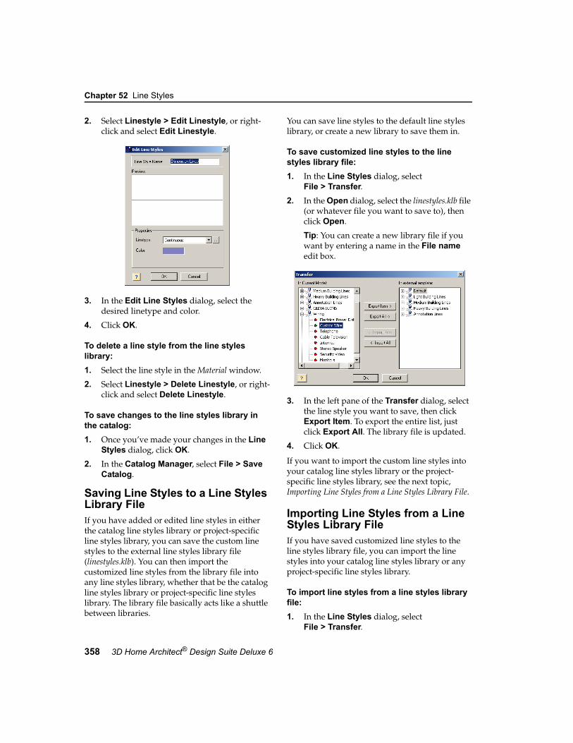
Chapter 52 Line Styles
358 3D Home Architect® Design Suite Deluxe 6
2. Select Linestyle > Edit Linestyle, or right-click and select Edit Linestyle.
3. In the Edit Line Styles dialog, select the desired linetype and color.
4. Click OK.
To delete a line style from the line styles library:1. Select the line style in the Material window.
2. Select Linestyle > Delete Linestyle, or right-click and select Delete Linestyle.
To save changes to the line styles library in the catalog:1. Once you’ve made your changes in the Line
Styles dialog, click OK.
2. In the Catalog Manager, select File > Save Catalog.
Saving Line Styles to a Line Styles Library FileIf you have added or edited line styles in either the catalog line styles library or project-specific line styles library, you can save the custom line styles to the external line styles library file (linestyles.klb). You can then import the customized line styles from the library file into any line styles library, whether that be the catalog line styles library or project-specific line styles library. The library file basically acts like a shuttle between libraries.
You can save line styles to the default line styles library, or create a new library to save them in.
To save customized line styles to the line styles library file:1. In the Line Styles dialog, select
File > Transfer.2. In the Open dialog, select the linestyles.klb file
(or whatever file you want to save to), then click Open.
Tip: You can create a new library file if you want by entering a name in the File name edit box.
3. In the left pane of the Transfer dialog, select the line style you want to save, then click Export Item. To export the entire list, just click Export All. The library file is updated.
4. Click OK.
If you want to import the custom line styles into your catalog line styles library or the project-specific line styles library, see the next topic, Importing Line Styles from a Line Styles Library File.
Importing Line Styles from a Line Styles Library FileIf you have saved customized line styles to the line styles library file, you can import the line styles into your catalog line styles library or any project-specific line styles library.
To import line styles from a line styles library file:1. In the Line Styles dialog, select
File > Transfer.

Customizing the Linetypes Library
User’s Guide 359
52
2. In the Open dialog, select the linestyles.klb file (or whatever file you want to import line styles from), then click Open.
3. In the right pane of the Transfer dialog, select the custom line style you want to import, then click Import Item. Or, to import the entire list, just click Import All. The list in the left pane is updated.
4. Click OK.
Customizing the Linetypes LibraryThe linetypes library contains a list of pre-defined linetypes that you can apply to line styles. You may want to add or edit linetypes to suit your needs.
To access the linetypes library:1. Select File > Catalogs > Catalog Manager,
or right-click an element in the catalog panel and select Catalog Manager.
2. In the Catalog Manager, select Libraries > Linetypes. The Linetypes dialog appears.
Note: You can also access the linetypes library when editing a line style, by clicking one of the swatches, then clicking the Browse button in the Edit Line Styles dialog. If you do access the linetypes library this way, new or edited linetypes will be saved with the line style in the current drawing only. The line styles and linetypes libraries in the catalog will remain unchanged.
To edit a linetype:1. Select the linetype in the list.
2. In the Definition edit box, edit the linetype’s definition. Lines are defined by a series of distances separated by commas. Each number represents the length of either a line segment or space. Positive numbers create a line segment of the specified length. Negative numbers create a space of the specified length. For example, a dashed line may have a definition like 1/4”, -1/4”.
3. Once you’ve edited the linetype, click OK.
To add a linetype to the list:1. Click the Add Item button below the
linetypes list, or right-click in the left pane and select Add Item. A new entry is added to the list.
2. Type a name for the linetype and press ENTER.
3. In the Definition edit box, specify the linetype’s definition.
4. Once you’ve defined the linetype, click OK.
To delete a linetype from the list:1. Select the linetype in the list.
2. Right-click and select Delete, or click the Delete button below the linetypes list.
Note: You cannot delete the existing, pre-defined linetypes because they are being used.
To save changes to the linetypes library in the catalog:1. Once you’ve made your changes in the
Linetypes dialog, click OK.

Chapter 52 Line Styles
360 3D Home Architect® Design Suite Deluxe 6
2. In the Catalog Manager, select File > Save Catalog.

361
Chapter
When you insert text or dimensions in your drawing, they are always based on a style that determines how they look.
Text and dimension styles are stored in libraries. You can edit and create text and dimension styles to suit your needs.
If you want to change the style of text that you have inserted in your drawing, see Changing the Style of Text on page 275. If you want to change the style of a dimension in your drawing, see Changing the Style of a Dimension on page 282.
Text & Dimension Styles

Chapter 53 Text & Dimension Styles
362 3D Home Architect® Design Suite Deluxe 6
Things You Should Know About Editing Text StylesWhen you add or edit a text style through the Catalog Manager, the custom text style is saved with the catalog, and is only available when editing text styles in the catalog. If you add or edit a text style when editing text in your drawing (or an element that uses text), however, the customized text style is only available in the current project when editing text styles in your drawing. The text styles library in the catalog remains unchanged. This is because the text styles library in the catalog is separate from the text styles library in the current project.
The reason that there is a project-specific text styles library is so that any text styles used in your project are always saved with the project, making it possible to share your project with others and always maintain your customized text styles.
If you want text styles that you have customized in your catalog to be available in your project-specific text styles library, or vice versa, you can use the Transfer tool to save the custom text styles to the external text styles library file (Textstyles.tsl), then import the custom text styles from the library file into the other text styles library.
Tip: You can save text styles in your template drawing by opening the template drawing, then selecting Settings > Text Styles and creating your custom text style in the Text Styles dialog. The custom text styles will then be available in the project-specific text styles libraries of future projects that you base on the template drawing.
Customizing the Text Styles LibraryThe text styles library contains a number of pre-defined text styles that you can apply to text. You can edit the existing text styles, or create your own.
When you edit the text styles library in your catalog, the text styles are saved with your catalog. If you edit text styles while editing inserted text, or an element that uses text, the text styles are saved in the current drawing only.
To access the text styles library in the Catalog Manager:1. Select File > Catalogs > Catalog Manager,
or right-click an element in the catalog panel and select Catalog Manager.
2. In the Catalog Manager, select Libraries > Text Styles. The Text Styles dialog appears.
To access the text styles library through inserted text:1. Select the text in your drawing.
2. Right-click and select Properties, or select Edit > Modify Elements > Properties.
3. In the Text dialog, click the Text Style button. The Text Styles dialog appears. This is your project-specific text styles library.
To access the text styles library through the Settings menu:1. Select Settings > Text Styles. This is your
project-specific text styles library.

Saving Customized Text Styles to the Text Styles Library File
User’s Guide 363
53
To add a text style to the library:1. Right-click in the text style window
and select Add Item. Or, click the Add Item button below the text style window. A new entry is added to the list.
2. Type a name for the text style and press ENTER.
3. In the Properties area, define the text style.
Font. A set of text characters in a specific style and size.
Font Style. The style of text. Choices can include Regular, Italic, Bold, and Bold Italic.
Text Height. The size of text.
Text Color. The color of text. Click the swatch to access the Color dialog and select a color.
4. Click OK.
To edit a text style in the library:1. Select the text style in the list.
2. Edit the properties in the Properties area.
Font. A set of text characters in a specific style and size.
Font Style. The style of text. Choices can include Regular, Italic, Bold, and Bold Italic.
Text Height. The size of text.
Text Color. The color of text. Click the swatch to access the Color dialog and select a color.
3. Click OK.
Note: Clicking Reset will return a text style to the following default values: Arial, Regular, 4", Black.
To delete a text style from the library:1. Select the text style in the list.
2. Right-click and select Delete, or click the Delete button below the text styles window.
To save changes to the text styles library in the catalog:1. Once you’ve made your changes in the Text
Styles dialog, click OK.
2. In the Catalog Manager, select File > Save Catalog.
Saving Customized Text Styles to the Text Styles Library FileIf you have added or edited text styles in either the catalog text styles library or project-specific text styles library, you can save the custom text styles to the external text styles library file (Textstyles.tsl). You can then import the customized text styles from the library file into any text styles library, whether that be the catalog text styles library or project-specific text styles library. The library file basically acts like a shuttle between libraries.
You can save text styles to the default text styles library file, or create a new library to save them in.
To save customized text styles to the text styles library file:1. In the Text Styles dialog, click the Transfer
button.
2. In the Open dialog, select the Textstyles.tsl file (or whatever file you want to save to), then click Open.
Tip: You can create a new library file if you want by entering a name in the File name edit box.
3. In the left pane of the Transfer dialog, select the text style you want to save, then click Export Item. To export the entire list, just click Export All. The library file is updated.
4. Click OK.
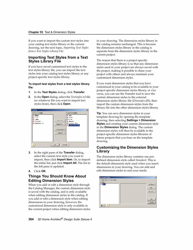
Chapter 53 Text & Dimension Styles
364 3D Home Architect® Design Suite Deluxe 6
If you want to import the custom text styles into your catalog text styles library or the current drawing, see the next topic, Importing Text Styles from a Text Styles Library File.
Importing Text Styles from a Text Styles Library FileIf you have saved customized text styles to the text styles library file, you can import the text styles into your catalog text styles library or any project-specific text styles library.
To import text styles from a text styles library file:1. In the Text Styles dialog, click Transfer.2. In the Open dialog, select the Textstyles.tsl file
(or whatever file you want to import text styles from), then click Open.
3. In the right pane of the Transfer dialog, select the custom text style you want to import, then click Import Item. Or, to import the entire list, just click Import All. The list in the left pane is updated.
4. Click OK.
Things You Should Know About Editing Dimension StylesWhen you add or edit a dimension style through the Catalog Manager, the custom dimension style is saved with the catalog, and is only available when editing dimension styles in the catalog. If you add or edit a dimension style when editing dimensions in your drawing, however, the customized dimension style is only available in the current project when editing dimension styles
in your drawing. The dimension styles library in the catalog remains unchanged. This is because the dimension styles library in the catalog is separate from the dimension styles library in the current project.
The reason that there is a project-specific dimension styles library is so that any dimension styles used in your project are always saved with the project, making it possible to share your project with others and always maintain your customized dimension styles.
If you want dimension styles that you have customized in your catalog to be available in your project-specific dimension styles library, or vice versa, you can use the Transfer tool to save the custom dimension styles to the external dimension styles library file (Dimstyles.dlb), then import the custom dimension styles from the library file into the other dimension styles library.
Tip: You can save dimension styles in your template drawing by opening the template drawing, then selecting Settings > Dimension Styles and creating your custom dimension style in the Dimension Styles dialog. The custom dimension styles will then be available in the project-specific dimension styles libraries of future projects that you base on the template drawing.
Customizing the Dimension Styles LibraryThe dimension styles library contains one pre-defined dimension style called Standard. This is the default dimension style used when you insert dimensions in your drawing. You can add and edit dimension styles to suit your needs.

Dimension Style Properties
User’s Guide 365
53
When you edit the dimension styles library in your catalog, the dimension styles are saved with your catalog. If you edit dimension styles while editing inserted dimensions, the dimension styles are saved in the current drawing only.
To access the dimension styles library in the Catalog Manager:1. Select File > Catalogs > Catalog Manager,
or right-click an element in the catalog panel and select Catalog Manager.
2. In the Catalog Manager, select Libraries > Dimension Styles. The Dimension Styles dialog appears.
To access the dimension styles library through inserted dimensions:1. Select the dimension in your drawing.
2. Right-click and select Properties, or select Edit > Modify Elements > Properties. The Dimension Styles dialog appears. This is your project-specific dimension styles library.
To access the dimension styles library through the Settings menu:1. Select Settings > Dimension Styles. This is
your project-specific dimension styles library.
To add a new dimension style to the list:1. Right-click in the dimension style
window and select Add Item. Or, click the Add Item button below the dimension style window. A new entry is added to the list.
2. Type a name for the dimension style and press ENTER.
3. Click the Edit button, then define the dimension style. See Dimension Style Properties on page 365.
4. Click OK.
To edit a dimension style:1. Select the dimension style in the list.
2. Click Edit.
3. Define the dimension in the Edit Dimension Styles dialog. See Dimension Style Properties on page 365.
4. Click OK.
To delete a dimension style from the library:1. Select the dimension style in the list.
2. Right-click and select Delete, or click the Delete button below the dimension styles window.
To save changes to the dimension styles library in the catalog:1. Once you’ve made your changes in the
Dimension Styles dialog, click OK.
2. In the Catalog Manager, select File > Save Catalog.
Dimension Style PropertiesYou can control a dimension’s line, arrow and text style properties.
Anatomy of a Dimension
Lines and Arrows
ExtensionLine
Text
Arrow,Tick orDot
DimensionLine

Chapter 53 Text & Dimension Styles
366 3D Home Architect® Design Suite Deluxe 6
Arrow TypeYou can specify an arrow type for dimensions and leaders (leaders are used with the Text with Leader tool). Choose an arrow, dot or tick for your arrow type.
The properties below the Arrow Type selection window (Extension Offset, Dimension Offset, etc.) vary depending on the arrow type selected. As you make different selections, the dimension updates in the preview window.
Dimension Text
UnitsThe units (e.g. feet and inches) and precision used to display the dimension value.
Override system units: Uses the unit of measure specified in the Edit Dimension Styles dialog instead of the unit of measure specified in the program settings.
Type: Choose from Feet-Inches, Millimeters, Centimeters, Meters or Inches.
Precision: For Feet-Inches, the choices are whole units (0, 1/2, 1/4 and so on). For metric units, the choices are number of decimal places you can use.
Text StyleRefers to the font, font style, text height and color of the dimension text. Click Text Style to select a style.
Vertical Text PositionThis is the vertical position of the dimension text relative to the dimension line.
Vertically Centered: Text is placed inside the dimension line.
Horizontal Text: Forces the dimension text to always be horizontal, regardless of the dimension line's angle.
Above Dimension Line: Text is placed above the dimension line.
Distance: Distance between the text and the dimension line when placing text above the dimension line.
Horizontal Text PositionThis is the position of the dimension text relative to the ends of the dimension line.
Centered: Centers the text inside the dimension line.
Distance from first end: Places the text a specific distance from the first end of the dimension. Specify the distance in the Distance edit box.
Distance from the second end: Places the text a specific distance from the second end of the dimension. Specify the distance in the Distance edit box.

Saving Customized Dimension Styles to the Dimension Styles Library File
User’s Guide 367
53
Line StylesYou can select a different line style for the dimension line, extension lines and arrows. A line style determines the linetype and color.
To assign a different line style to a dimension component, select the component in the left pane, then select the desired line style in the right pane.
For information about creating custom line styles, see the Line Styles chapter on page 355.
Saving Customized Dimension Styles to the Dimension Styles Library FileIf you have added or edited dimension styles in either the catalog dimension styles library or project-specific dimension styles library, you can save the custom dimension styles to the external dimension styles library file (Dimstyles.dlb). You can then import the customized dimension styles from the library file into any dimension styles library, whether that be the catalog dimension styles library or project-specific dimension styles library. The library file basically acts like a shuttle between libraries.
You can save dimension styles to the default dimension styles library file, or create a new library to save them in.
To save dimension styles to the dimension styles library file:1. In the Dimension Styles dialog, click the
Transfer button.
2. In the Open dialog, select the Dimstyles.dlb file (or whatever file you want to save to), then click Open.
Tip: You can create a new library file if you want by entering a name in the File name edit box.
3. In the left pane of the Transfer dialog, select the dimension style you want to save, then click Export Item. To export the entire list, just click Export All. The library file is updated.
4. Click OK.
If you want to import the custom dimension styles into your catalog dimension styles library or the project-specific dimension styles library, see the next topic, Importing Dimension Styles from a Dimension Styles Library File.
Importing Dimension Styles from Dimension Styles Library FileIf you have saved customized dimension styles to the dimension styles library file, you can import the dimension styles into your catalog dimension styles library or any project-specific dimension styles library.
To import dimension styles from a dimension styles library file:1. In the Dimension Styles dialog, click
Transfer.

Chapter 53 Text & Dimension Styles
368 3D Home Architect® Design Suite Deluxe 6
2. In the Open dialog, select the Dimstyles.dlb file (or whatever file you want to import dimension styles from), then click Open.
3. In the right pane of the Transfer dialog, select the custom dimension style you want to import, then click Import Item. Or, to import the entire list, just click Import All. The list in the left pane is updated.
4. Click OK.

369
Chapter
Light sources are basically light bulbs. Light sources are contained in a light source library which is accessible through the Catalog Manager as well as the Lights property page of light fixtures. You can edit existing light sources as well as import your own light source files into the library.
If you want to change a light fixture’s light source, see Editing a Light Fixture’s Light Source on page 129.
Light Sources

Chapter 54 Light Sources
370 3D Home Architect® Design Suite Deluxe 6
Things You Should Know About Editing Light SourcesLight sources are basically light bulbs. They are applied to light fixtures. When you add or edit a light source through the Catalog Manager, the custom light source is saved with the catalog, and is only available when editing light sources in the catalog. If you add or edit a light source when editing a light fixture that has been inserted in your drawing, however, the customized light source is only available in the current project when editing the properties of inserted light fixtures. The light source library in the catalog remains unchanged. This is because the light source library in the catalog is separate from the light source library in the current drawing.
The reason that there is a project-specific light source library is so that any light sources used in your project are always saved with the project, making it possible to share your project with others and always maintain your customized light sources.
If you want light sources that you have customized in your catalog to be available in your project-specific light source library, or vice versa, you can use the Transfer tool to save the custom light sources to the external light source library file (Lights.llb), then import the custom light source from the library file into the other light source library.
Customizing the Light Source LibraryThe light source library contains an assortment of light sources, mainly fluorescent and incandescent light bulbs, that can be applied to lighting fixtures.
You can customize the light source library by adding and editing light sources. Most manufacturers of lighting equipment provide downloadable .IES photometric data files free of charge on their web sites for use in lighting calculations. Once you’ve added a light source to your library, you can edit its intensity and color if you want.
Light sources are listed in groups so you can organize and find them easily. You can create, rename and delete groups.
When you edit the light source library in your catalog, the light sources are saved with your catalog. If you edit the light source library while editing an element, the light sources are saved in the current drawing only.
To access the light source library in the Catalog Manager:1. Select File > Catalogs > Catalog Manager,
or right-click an element in the catalog panel and select Catalog Manager.
2. In the Catalog Manager, select Libraries > Light Sources. The Light Sources dialog appears.

Saving Customized Light Sources to the Light Source Library File
User’s Guide 371
54
To access the light source library through an inserted light fixture:1. Select the light fixture.
2. Right-click and select Properties, or select Edit > Modify Elements > Properties.
3. In the Lights dialog, select the Lights tab.
4. Click Add or Edit to access the light source library.
To add a group to the light source library:1. Right-click an existing group and select
Add Group, or click the Add Group button below the light source window. An entry is added to the list.
2. Type a name for the group, then press ENTER.
To delete a group from the line styles library:1. Select the group to delete.
2. Right-click and select Delete Group, or click the Delete button below the light source window.
Note: A group cannot be deleted if it contains light sources.
To add a light source to the list:1. Select the group you want to add the light
source to.
2. Click the Add Item button below the light source window, or right-click in the light source window and select Add Item. A new entry is added to the list.
3. Type a name for the light source and press ENTER.
4. Click the Load IES File button.
5. Locate and select the *.ies file and click Open. The filename is displayed in the right pane of the Light Sources dialog.
6. If you want to change the intensity of the light, specify the desired percentage in the Scale edit box. For example, if the light source is a 60 Watt bulb, a value of 50% would make the bulb function like a 30 Watt bulb.
7. If you want to change the color of the light, click the Color edit box and make a selection from the Color dialog.
To apply a different IES file to a light source:1. Select the light source in the list.
2. Click the Load IES File button.
3. Locate and select the *.ies file and click Open. The filename is displayed in the right pane of the Light Sources dialog.
To edit the intensity of a light source:1. Select the light source in the list.
2. In the Scale edit box, specify how much you want to scale the intensity in terms of a percentage. For example, if the light source is a 60 Watt bulb, a value of 50% would make the bulb function like a 30 Watt bulb.
To edit the color of a light source:1. Select the light source in the list.
2. Click the Color edit box.
3. In the Color dialog, select the color you want, then click OK.
To delete a light source from the library:1. Select the light source in the list.
2. Right-click and select Delete, or click the Delete button below the light source window.
Saving Customized Light Sources to the Light Source Library FileIf you have added or edited light sources in either the catalog light source library or project-specific light source library, you can save the custom light sources to the external light source library file (Lights.llb). You can then import the customized light sources from the library file into any light
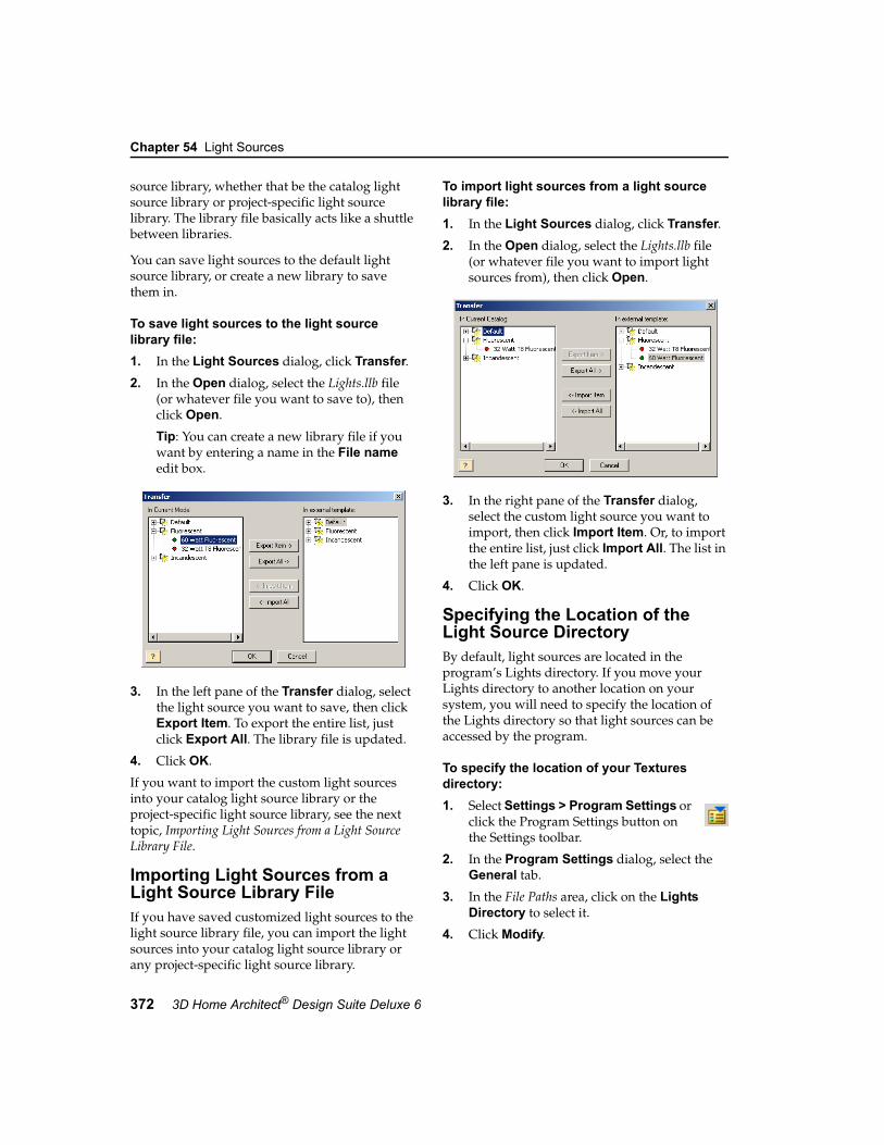
Chapter 54 Light Sources
372 3D Home Architect® Design Suite Deluxe 6
source library, whether that be the catalog light source library or project-specific light source library. The library file basically acts like a shuttle between libraries.
You can save light sources to the default light source library, or create a new library to save them in.
To save light sources to the light source library file:1. In the Light Sources dialog, click Transfer.2. In the Open dialog, select the Lights.llb file
(or whatever file you want to save to), then click Open.
Tip: You can create a new library file if you want by entering a name in the File name edit box.
3. In the left pane of the Transfer dialog, select the light source you want to save, then click Export Item. To export the entire list, just click Export All. The library file is updated.
4. Click OK.
If you want to import the custom light sources into your catalog light source library or the project-specific light source library, see the next topic, Importing Light Sources from a Light Source Library File.
Importing Light Sources from a Light Source Library FileIf you have saved customized light sources to the light source library file, you can import the light sources into your catalog light source library or any project-specific light source library.
To import light sources from a light source library file:1. In the Light Sources dialog, click Transfer.2. In the Open dialog, select the Lights.llb file
(or whatever file you want to import light sources from), then click Open.
3. In the right pane of the Transfer dialog, select the custom light source you want to import, then click Import Item. Or, to import the entire list, just click Import All. The list in the left pane is updated.
4. Click OK.
Specifying the Location of the Light Source DirectoryBy default, light sources are located in the program’s Lights directory. If you move your Lights directory to another location on your system, you will need to specify the location of the Lights directory so that light sources can be accessed by the program.
To specify the location of your Textures directory:1. Select Settings > Program Settings or
click the Program Settings button on the Settings toolbar.
2. In the Program Settings dialog, select the General tab.
3. In the File Paths area, click on the Lights Directory to select it.
4. Click Modify.

Specifying the Location of the Light Source Directory
User’s Guide 373
54
5. In the Browse For Folder dialog, locate the folder containing your light sources, then click OK.
6. Click OK in the Program Settings dialog.


375
Chapter
When you run the House Builder Wizard or Kitchen Builder Wizard, you are asked to select a style for your house or kitchen, such as “Country” or “Traditional”. The configuration you choose determines the appearance of elements used to build your house or kitchen.
You can specify your own custom configurations that can be used when running the House Builder Wizard or Kitchen Builder Wizard in any project.
Wizard Configurations

Chapter 55 Wizard Configurations
376 3D Home Architect® Design Suite Deluxe 6
Creating a Custom House Builder Wizard ConfigurationA House Builder Wizard configuration determines what elements are used for exterior walls, roofs, floors, ceilings, foundation walls and footings. You are asked to select a configuration for your house when you run the House Builder Wizard.
You can edit any of the existing configurations that are available in the House Builder Wizard, or create your own. Customized configurations are saved automatically and will be available when you run the House Builder Wizard in the current project, or any other project.
To access the building configuration library:1. Select File > Catalogs > Catalog Manager,
or right-click any element in the catalog panel and select Catalog Manager.
2. In the Catalog Manager dialog, select Libraries > Building Configuration.
To add a new configuration to the list:1. Click the Add Item button below the
left pane, or right-click in the left pane and select Add Item. An entry is added to the list.
2. Type a name for the configuration, then press ENTER.
To edit a building configuration:1. Select the configuration in the list. The
element selections for the configuration are listed in the center pane.
2. In the center pane, select an element type you want to specify a style for.
3. Click the Select button.
4. In the catalog dialog, select the specific style you want to apply to the selected element type, then click OK.
5. Continue selecting styles for the remaining element types.
To delete a configuration from the list:1. Select the configuration in the list.
2. Click the Delete button below the left pane, or right-click in the left pane and select Delete.
Creating a Custom Kitchen Builder Wizard ConfigurationA Kitchen Builder Wizard configuration determines what types of cabinets and appliances are used in your kitchen. You are asked to select a configuration for your kitchen when you run the Kitchen Builder Wizard.
You can edit any of the existing configurations that are available in the Kitchen Builder Wizard, or create your own. Customized configurations are saved automatically and will be available

Creating a Custom Kitchen Builder Wizard Configuration
User’s Guide 377
55
when you run the Kitchen Builder Wizard in the current project, or any other project.
To access the kitchen configuration library:1. Select File > Catalogs > Catalog Manager,
or right-click any element in the catalog panel and select Catalog Manager.
2. In the Catalog Manager dialog, select Libraries > Kitchen Configuration.
To add a new configuration to the list:1. Click the Add Item button below the
left pane, or right-click in the left pane and select Add Item. An entry is added to the list.
2. Type a name for the configuration, then press ENTER.
To edit a kitchen configuration:1. Select the configuration in the list. The
element selections for the configuration are listed in the center pane.
2. In the center pane, select an element type you want to specify a style for.
3. Click the Select button.
4. In the catalog dialog, select the specific style you want to apply to the selected element type, then click OK.
5. Continue selecting styles for the remaining element types.
To delete a configuration from the list:1. Select the configuration in the list.
2. Click the Delete button below the left pane, or right-click in the left pane and select Delete.


379
This handy Glossary contains definitions of construction terms, abbreviations and technical terms used in the program and in this User’s Guide. Entries are listed in alphabetical order for your convenience.
Glossary

Glossary
380 3D Home Architect® Design Suite Deluxe 6
Glossary
AAlkaline – Having a PH of more than 7.
Alt Code – Alternate Code. An extra identification code that is used to link an element in the program's catalog to the databases of other applications.
Ambient – A general level of light that is everywhere in the scene.
Angle Snap – Makes elements move/rotate at specific increments (angles).
Antialiasing – A method of improving image quality by smoothing out jagged edges. This is achieved by adjusting pixel positions or setting pixel intensities so that there is a more gradual transition between the color of a line and the background color.
Array – A method of copying an element into a pattern of rows and/or columns.
Artifacts – Fuzz or distortion in a graphic image or sequence of video images. Large digital pixels (“blocks”) and jerkiness in the video stream are examples of artifacts.
Aspect Ratio – The ratio of width to height.
Automatic Save – Saves your drawing for you at specified intervals without prompting.
Awning Window – A window having a sash hinged on pins at the two top or bottom corners of the frame. It opens outward.
BBacksplash – A vertical surface designed to protect the wall behind a stove or countertop.
Balustrade – A railing consisting of balusters (spindles) attached to a top rail. Used along stairs, landings, porches, decks, etc. Also called a banister.
Baseboard – A board or moulding along the base of a wall. Also called skirting.
Bay Window – A window made up of three sash units that project out from the wall. Usually includes a roof structure.
Beam – In a deck frame, structural member supported by posts that acts to support the deck’s floor joists.
Berm – A mound or bank of soil without formal sides. You often see large berms on the sides of highways, which are used for noise control.
Bi-Fold Doors – Narrow doors that are hinged to fold against each other and flat against the jamb.
Bird's Mouth – The notch cut in the lower end of a rafter to fit it to the top plate of a wall.
BLD – BUILD file. The drawing file produced by the program. The extension given to the program's drawing files.
BMP – Bitmap. An image file whose bits are referenced to pixels.
Bow Window – A type of bay window made up of several window units set at slight angles to form a curve.
CCasement Window – A window having a sash hinged on pins at the top and bottom corners of one side. It opens outward by means of a crank.
Catalog Directory –The directory containing the Master Catalog and other catalogs that you have created.
Catalog Panel – The window on the right side of the screen that displays the contents of the current catalog.
Ceiling Height – The height of the underside of a ceiling surface relative to the floor level.
Chair Rail – A decorative moulding applied horizontally to a wall inside a room at a height of about 3 feet. Used to prevent chairs from marring the wall.
Collision Control – An intelligent drawing aid that prevents elements from being inserted where they won't fit.

Glossary
User’s Guide 381
Commander – An editing window that appears when certain functions are chosen. It provides precise control over such things as distance and direction.
Complexity – The level of detail shown when elements are displayed.
Cove Molding – A molding with a concave face used as trim.
Crawlspace – The shallow area beneath a house enclosed by the foundation walls.
Crown Molding – A decorative molding along the top of a wall.
Cut Line – The symbol displayed on stairs in Plan view that illustrates the horizontal section cut at eye level.
DDaylight Saving Time – Time usually one hour ahead of standard time.
Delimiter – A character that marks the beginning or end of a unit of data.
Diffuse – The amount of color that is reflected when an element is illuminated by a light.
Division – A construction division identification. In North America, CSI divisions are used.
DLB File – Dimension Style Library File. Contains Dimension Styles.
Double Roof – A type of hip roof in which the slope to all four sides is broken into two slopes. Both slopes have a pitch.
DPI – Dots per inch. The measurement of resolution for printers.
Drag and Drop Mode – The default mode you are in when you select an element for editing. You can move and rotate elements with your mouse when you are in Drag and Drop Mode.
Drawing Aids – Tools that control the way your cursor works and the way elements are inserted.
Drywall — Gypsum, sometimes with additives, made into paper-covered sheets for use an interior wall or ceiling covering.
Duplicate – Copies a selected element on the same location.
Dutch Gable – A combination of a hip and gable roof. On either end, the lower segment is a hip roof and the upper segment is a gable end. Also known as a Dutch Hip Roof or a Full Return Gable.
DWG – Standard file format for saving vector graphics in applications like AutoCAD.
DXF – Drawing Exchange Format. An ASCII or binary file format of a CAD drawing.
EEditor – A software application capable of editing text.
Element – A specific type of element, such as a door, having its own distinct properties (size, appearance, etc.).
Elevation – 1. The front, back and side views of a building. 2. The height of an element above the floor or terrain.
Estimate – A report containing a listing of materials, quantities, unit costs, and total cost.
FFace Slider – Two or more doors that open by sliding to the side in front or behind each other. Also called bypass doors.
Fascia – A flat wood or plywood strip nailed to the overhanging ends of rafters.
Filter – To exclude an element or location from being displayed, quantified or selected.
Fixed Window – A window whose sash is permanently fixed in the frame.
Floor Level – The height of a floor (location) above the ground (0).
Fold-Back Stairs – Stairs that have two flights separated by a landing and that make a complete 180-degree turn. Sometimes called Scissor Stairs.
Fold-Up Door – A door made up of a number of narrow panels that opens overhead by folding up like an accordion.

Glossary
382 3D Home Architect® Design Suite Deluxe 6
Foundation – The supporting portion of a structure below the ground floor construction, or below grade, including the footings.
GGable Roof – A roof with two sloping sides (as opposed to a Hip Roof, with four sloping sides).
Girt Wall – A wall built up of horizontal structural members that are suspended between vertical columns. Usually found in industrial buildings.
Glass Slider – A door having a wood or aluminum frame fitted with one fixed glass panel and one sliding glass panel. Often called a patio door.
Group – A container for a list of specific element types. For example, doors are organized in groups such as Bi-fold and Single Hinged.
HHatching – A pattern of lines used to fill a particular area of your drawing and to represent the material used for that area (e.g. concrete).
Head Height –The height at which the tops of openings, doors and windows are located relative to the floor level.
Header – The structural members placed horizontally over doors, windows and wall openings.
Hidden Line – A view mode where hidden lines are removed from the view, leaving only surfaces displayed.
Highlite – A pane of glass located at the top of a window or door.
Hinged Door – Any type of door that swings open.
Hip Roof – A roof with four sloping sides (as opposed to a Gable Roof, with two sloping sides).
HLB File – Pattern Library File. Contains hatching patterns.
Hopper Window – A window in which the sash is hinged on pins at the two bottom corners, and which opens inward.
Hung Window – A window having two sashes, and whose lower sash slides up and over the fixed, upper sash on the inside.
Hyperlinks – Jumps (links) to external document files or Web addresses.
IIES File – Name derived from Illuminating Engineering Society. A photometric data file (Lights file) containing Luminaire definition and information.
Interface – Program components that you see on the screen and use to perform tasks.
JJamb – The wood or metal pieces that form the sides and top of a door or window enclosure.
Joist – One of a parallel set of structural members used to support floor and ceiling loads. They, in turn, are supported by beams, girders, or bearing walls.
KKLB File – Line Styles Library File.
LLanding – A platform between flights of stairs or at the termination of a flight of stairs.
L-Winder Stairs – Stairs that ascend in an L-shape and that use wedge-shaped treads called winders to change direction.
Line Styles – Settings that determine the color and pattern of a line. Used in electrical wiring and dimension styles.
Lite – A pane of glass in a window or door.
LLB File – Lights Library File.
Locations – Drawing layers containing definitions for wall height, floor level, head height and ceiling level.
Louvre Window – A small, slatted window placed high in a gable end. Used mostly for ventilation.

Glossary
User’s Guide 383
Lumen – A Lumen is equal to one foot-candle (the amount of light one candle generates one foot away) falling on one SQUARE foot of area.
Luminaire – The international term for a piece of lighting equipment. The complete unit including lamp, fixture, and other parts.
MMagnetic North – Magnetic North is the magnetic north pole. It is the focus of the planet's magnetic field and is the point magnetic compasses point toward.
Mansard Roof – A type of hip roof in which the slope to all four sides is broken into two slopes. The upper slope is nearly or completely flat, while the lower slope has a sharp pitch. Also known as a French gable roof.
MLB File – Materials Library File.
Mono Footing – A pad of masonry, usually concrete, that is wider than the column it supports. Used to transfer the load of the column.
Mullion – Thin horizontal and vertical members that divide the individual panes of glass in a window.
NNewel – The main post to which the end of a railing is attached.
NLB File – Linetype Library File.
Nosing – The portion of a stair tread that projects over the riser. Also, the projecting edge of a countertop.
OOpen GL – A 3D graphics Application Programming Interface (API) that includes routines for shading, texture mapping, texture filtering, anti-aliasing, lighting, geometry transformations, etc.
Opening – A cutout in a wall.
Ortho – A Drawing Aid that restricts drawing to straight up, down, left, or right.
Orthogonal View – An alternate name for Parallel View in which all drawing lines are parallel and the effect of distance is eliminated. Contrasts with Perspective View.
Overhang – The part of the roof that extends over the side wall. Also, the distance from the side wall to the fascia.
PPan – A control that allows you to move the on-screen view by dragging up, down, left, or right.
Parallel View – A 3D view that eliminates the effect of distance from a view. In Parallel View, all drawing lines are parallel. Contrasts with Perspective View. Parallel View is sometimes called Orthogonal View.
Parametric – Having a set of physical properties that determines the characteristics of an element.
Percent (%) Below Horizon – The percentage that you want the background to appear below ground level (absolute zero).
Perspective View – A 3D view in which the scale of an element decreases according to its distance from the viewer. Drawing lines converge to a vanishing point. Perspective View represents the way an element would appear to the human eye.
Photometric Data File – A file that allows you to define complex light distributions based on physical lamp properties. When loading a photometric file, a photometric web is constructed that defines the intensity of light for any direction from a light source.
Pixel – A word invented by combining the two words “picture” and “element”. The smallest unit of color on a computer display. Size varies by resolution.
Pixel Search Distance – The Pixel Search Distance determines how close your cursor (which is attached to an element you are inserting) needs to be to an existing element before Object Snap occurs.
Plan View – A flat, 2D view from above.

Glossary
384 3D Home Architect® Design Suite Deluxe 6
Plate (Top Plate) – The top member of a framed wall upon which the rafters and ceiling joists rest.
Plateau – A relatively large, flat area of land situated above the adjacent land.
Pocket Door – A door that rolls on an overhead track into a frame or pocket hidden in the wall.
Project Directory – The location of the default directory in which projects are stored.
Project Estimate – A report containing a listing of materials, quantities, unit costs, and total cost.
QQuantity Report – A list of the type and quantity of materials in your model. Also known as a Materials List or Bill of Materials.
RRafter – Structural members that make up the framing for a roof and roof overhang, and that support the sheathing and roofing materials.
Rake – To incline from the perpendicular.
Render – To display a 3D model with surfaces, textures, lighting and shading.
Rendered Mode – A display mode where solid colors and textures are applied to surfaces, creating a realistic 3D effect.
Rendered Outline Mode – A display mode where solid colors and textures are applied to elements, and surfaces are outlined with a black line for high definition.
Retaining Wall – A wall constructed to contain a lateral force, such as a bank of dirt.
Riser – The vertical board placed between the treads of a staircase.
Roller Door – A door made of hinged, horizontal steel or wood panels that move on rollers in overhead and side tracks.
Rough Opening – The opening created in a wall to receive a door or window frame.
SSaddle – A small, double-sloping roof built behind upper-story walls or the back side of a chimney to divert water around the wall or chimney.
Sash – A frame that holds one or more panes of glass and that is set into the window frame.
Seat Cut – The horizontal cut that is made when cutting a bird's mouth in a rafter.
Shininess – The ability of a texture to reflect light.
Slab – Concrete pavement, i.e. driveways, garages, and basement floors.
Slope – Ground that forms an incline.
Snap Angle – The increment angle your cursor will snap at (if Angle Snap is enabled).
Soffit – The area below the eave and overhang. The underside where the roof overhangs the walls.
Specular – A shininess factor that determines the amount of highlighting you see on an element from light sources.
Split L-Shaped Stairs – Stairs that ascend in an L-shaped direction and whose landing is split on a diagonal to make the change in direction.
Spreadsheet – A table of values arranged in rows and columns.
Status Bar – The bar below the drawing area that contains the Help message for the current state or tool. Also contains drawing aid buttons.
Stringer – The inclined side of a stair that supports the treads and risers.
Strip Footings – A flat, masonry section, usually concrete, that is wider than the wall it supports. Used to transfer the vertical load of the wall.
Studs – Members inserted vertically in a wall frame.
Suspended Ceiling – A grid of T-shaped bars hung on wires from overhead support framing, into which removable panels are inserted to form

Glossary
User’s Guide 385
a finished ceiling that allows easy access to the area above it. Typically found in office buildings and basements.
TTemplate – A set of pre-defined properties that determines the setup and outcome of something (like a report).
Temporary Directory – The default directory in which temporary files generated by the program are saved.
Terrain – A piece of land.
Tile Height – The height of one tile in a texture pattern. The program generates large images by “tiling” texture bitmaps horizontally and vertically.
Tilt Door – A door consisting of a single leaf that opens overhead by tilting up (e.g. Tilt Garage Door).
Toe Space – A recessed area between the bottom of a cabinet and the floor that allows you to stand close to the cabinet. Also called a toe kick.
Transom – A member between a door or window and a sidelite or highlite frame.
Transparency – The degree to which a texture can be penetrated by light.
Tread – The horizontal part of a stair that is stepped on.
True North – True North is the geographic North Pole. It is located at 90 degrees North latitude and all lines of longitude converge at the pole.
Truss – A variety of members made up into a series of triangles. Used for constructing roofs.
TSL File – Text Style Library File
UU-Winder Stairs – Stairs that ascend in a U-shaped direction.
VView Filter – A dialog used for displaying and hiding elements and/or locations, and controlling the selectability of elements.
Vent Window – A window made up of two or more segments with one segment acting as a vent.
VRML – Virtual Reality Modeling Language. The open standard for virtual reality on the Internet.
WWinder – One of the wedge-shaped treads that make up a winding or spiral staircase.
Windowing – A selection method where you click and drag a rectangle, from left to right, around elements you want to select.
Wireframe View – The default 3D view where all lines making up elements are displayed. It allows you to see through elements.
WRL File – WORLD file. Capable of being viewed in VRML viewers.
XX Axis – One of the three drawing axes. An X coordinate specifies a horizontal distance.
YY Axis – One of the three drawing axes. A Y coordinate specifies a vertical distance.
ZZ Axis – One of the three drawing axes. The Z coordinate indicates either elevation or depth.
Z Buffer – A block of memory used to store the Z-axis value of a pixel on the screen. Higher depth values improve detail of 3D display but may slow the system.
Zenith - Culminating point.
Zoom Realtime – Magnifies or shrinks the view as you click and drag with your mouse.
Zoom to Fit – Zooms the drawing to the extents of the drawing area, creating a maximized view of your entire design.
Zoom Window – Magnifies an area of your drawing that you select by windowing.


387
When you want to know where to find something in the catalog, this is the place to look. The Catalog Index contains a list of elements — everything from air hockey tables to water heaters — and tells you what tool to select to access each one, and what group to select in the catalog. Items are listed in alphabetical order for your convenience.
Catalog Index

Catalog Index
388 3D Home Architect® Design Suite Deluxe 6
Catalog IndexItems Tool to Select Catalog GroupsAir Hockey Table Insert > Interiors > Furniture Recroom Furniture
Air Returns Insert > Interiors > HVAC Ventilation
Aquariums Insert > Interiors > Accessories Aquariums
Arbors Insert > Landscape > Exterior Structures Arbors and Trellis
Area Rugs Insert > Interiors > Accessories Area Rugs
Armchairs Insert > Interiors > Furniture Living Room Furniture
Armoire Insert > Interiors > Furniture Bedroom Furniture
Arrows, north Insert > Landscape > Exterior Accessories
North Arrows
Badminton Courts Insert > Landscape > Exterior Structures Sports
Barbecues Insert > Landscape > Exterior Accessories
Outdoor Cooking and Heating
Bark Insert > Landscape > Fills Fills
Barstools Insert > Interiors > Furniture Recroom Furniture
Basinet Insert > Interiors > Furniture Bedroom Furniture
Basketball Nets and Courts
Insert > Landscape > Exterior Structures Sports
Bathroom Vanities Insert > Interiors > Cabinets Bathroom Vanities
Bathtubs Insert > Interiors > Plumbing Fixtures Tubs and Showers
Beds Insert > Interiors > Furniture Bedroom Furniture
Beer Bottle Insert > Interiors > Furniture Recroom Furniture
Benches, exterior Insert > Landscape > Exterior Furniture Benches and Storage

Catalog Index
User’s Guide 389
Benches, interior Insert > Interiors > Furniture Living Room Furniture
Bidets Insert > Interiors > Plumbing Fixtures Toilets and Bidets
Billiards Tables Insert > Interiors > Furniture Recroom Furniture
Bird Baths, Feeders & Houses
Insert > Landscape > Exterior Accessories
Decorative Accessories
Blender Insert > Interiors > Appliances Kitchen Appliances
Blinds Insert > Interiors > Accessories Window Treatments
Books Insert > Interiors > Accessories Decorative
Bookshelves Insert > Interiors > Furniture Bedroom FurnitureOffice Furniture
Borders, garden Insert > Landscape > Exterior Accessories
Decorative Accessories
Built-in Ovens Insert > Interiors > Appliances Kitchen Appliances
Cabinets, base Insert > Interiors > Cabinets Single Door Base CabinetsDouble Door Base CabinetsBase Drawer UnitsBase Corner CabinetsBase Island CabinetsBathroom Vanities
Cabinets, upper Insert > Interiors > Cabinets Upper Corner CabinetsUpper CabinetsUpper Island Cabinets
Cable Outlets Insert > Interiors > Electrical Outlets
Candle Sticks Insert > Interiors > Accessories Decorative
Card Table Insert > Interiors > Furniture Recroom Furniture
Cars Insert > Landscape > Exterior Accessories
Other Outdoor Items
CD Stands Insert > Interiors > Furniture Living Room Furniture
Catalog IndexItems Tool to Select Catalog Groups

Catalog Index
390 3D Home Architect® Design Suite Deluxe 6
Ceiling Fans Insert > Interiors > Lighting Ceiling Lights
Chairs, living room Insert > Interiors > Furniture Living Room Furniture
Chairs, patio Insert > Landscape > Exterior Furniture Chairs
Chairs, recroom Insert > Interiors > Furniture Recroom Furniture
Change Screen Insert > Interiors > Furniture Bedroom Furniture
Change Table Insert > Interiors > Furniture Bedroom Furniture
Chests Insert > Interiors > Furniture Bedroom Furniture
Chimney Insert > Interiors > HVAC Ventilation
Clocks Insert > Interiors > Electronics Clocks
Closet Rods/Shelves
Insert > Interiors > Furniture Bedroom Furniture
Coffee Tables Insert > Interiors > Furniture Living Room Furniture
Columns, decorative
Insert > Landscape > Exterior Accessories
Decorative Accessories
Computer Insert > Interiors > Electronics Computer Components
Concrete Edging Insert > Landscape > Edging Rail Edging
Concrete fills Insert > Landscape > Fills Fills
Cooktops Insert > Interiors > Appliances Kitchen Appliances
Corner Accents Insert > Landscape > Exterior Accessories
Decorative Accessories
Cribs Insert > Interiors > Furniture Bedroom Furniture
Cubicals Insert > Interiors > Furniture Office Furniture
Catalog IndexItems Tool to Select Catalog Groups

Catalog Index
User’s Guide 391
Cups Insert > Interiors > Accessories Dining Room/Kitchen Accessories
Curtains Insert > Interiors > Accessories Window Treatments
Dart Board Insert > Interiors > Furniture Recroom Furniture
Deck Box Insert > Landscape > Exterior Furniture Benches and Storage
Desks Insert > Interiors > Furniture Office Furniture
Dining Sets Insert > Interiors > Furniture Dining Room/Kitchen Furniture
Dishes Insert > Interiors > Accessories Dining Room/Kitchen Accessories
Dishwasher Insert > Interiors > Appliances Kitchen Appliances
Doghouses Insert > Landscape > Exterior Structures Storage & Enclosures
Door mats Insert > Interiors > Accessories Decorative
Down Spout Insert > Interiors > Plumbing Fixtures Exterior Plumbing Fixtures
Drapes Insert > Interiors > Accessories Window Treatments
Dressers Insert > Interiors > Furniture Bedroom Furniture
Dry Bars Insert > Interiors > Furniture Recroom Furniture
Dryers Insert > Interiors > Appliances Laundry Appliances
DVD Player Insert > Interiors > Electronics Televisions
Edging Insert > Landscape > Edging Plastic EdgingPost EdgingRail Edging
End tables Insert > Interiors > Furniture Living Room Furniture
Entertainment Units Insert > Interiors > Furniture Living Room Furniture
Catalog IndexItems Tool to Select Catalog Groups
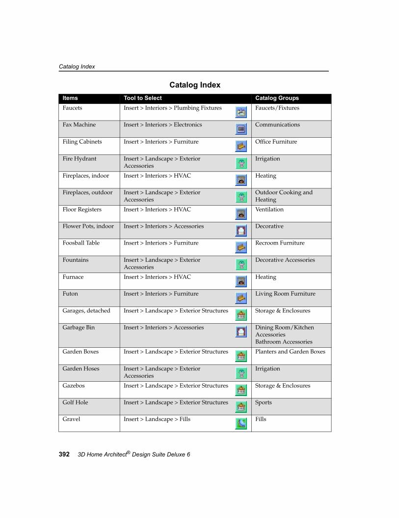
Catalog Index
392 3D Home Architect® Design Suite Deluxe 6
Faucets Insert > Interiors > Plumbing Fixtures Faucets/Fixtures
Fax Machine Insert > Interiors > Electronics Communications
Filing Cabinets Insert > Interiors > Furniture Office Furniture
Fire Hydrant Insert > Landscape > Exterior Accessories
Irrigation
Fireplaces, indoor Insert > Interiors > HVAC Heating
Fireplaces, outdoor Insert > Landscape > Exterior Accessories
Outdoor Cooking and Heating
Floor Registers Insert > Interiors > HVAC Ventilation
Flower Pots, indoor Insert > Interiors > Accessories Decorative
Foosball Table Insert > Interiors > Furniture Recroom Furniture
Fountains Insert > Landscape > Exterior Accessories
Decorative Accessories
Furnace Insert > Interiors > HVAC Heating
Futon Insert > Interiors > Furniture Living Room Furniture
Garages, detached Insert > Landscape > Exterior Structures Storage & Enclosures
Garbage Bin Insert > Interiors > Accessories Dining Room/Kitchen AccessoriesBathroom Accessories
Garden Boxes Insert > Landscape > Exterior Structures Planters and Garden Boxes
Garden Hoses Insert > Landscape > Exterior Accessories
Irrigation
Gazebos Insert > Landscape > Exterior Structures Storage & Enclosures
Golf Hole Insert > Landscape > Exterior Structures Sports
Gravel Insert > Landscape > Fills Fills
Catalog IndexItems Tool to Select Catalog Groups

Catalog Index
User’s Guide 393
Greenhouse Insert > Landscape > Exterior Structures Storage & Enclosures
Hammocks Insert > Landscape > Exterior Furniture Swings and Hammocks
Hoses, garden Insert > Landscape > Exterior Accessories
Irrigation
Hot Tubs Insert > Landscape > Exterior Structures Pools & Hot Tubs
House Templates Insert > Landscape > Exterior Structures House Templates
Islands, kitchen Insert > Interiors > Cabinets Base Island CabinetsUpper Island Cabinets
Jungle Gyms Insert > Landscape > Exterior Structures Playground
Kitchen Tables Insert > Interiors > Furniture Dining Room/Kitchen Furniture
Knife Sets Insert > Interiors > Accessories Dining Room/Kitchen Accessories
Lamps Insert > Interiors > Lighting Lamps
Lawn Edging Insert > Landscape > Edging Plastic Edging
Light Switches Insert > Interiors > Electrical Switches
Lights Insert > Interiors > Lighting Ceiling LightsLampsWall Lights
Lights, outdoor Insert > Landscape > Landscape Lighting Exterior FixturesGround LightingLight Posts
Lounge Chairs, outdoor
Insert > Landscape > Exterior Furniture Chairs
Loveseats Insert > Interiors > Furniture Living Room Furniture
Mail Boxes Insert > Landscape > Exterior Accessories
Other Outdoor Items
Medicine Cabinet Insert > Interiors > Accessories Bathroom Accessories
Merry-Go-Round Insert > Landscape > Exterior Structures Playground
Catalog IndexItems Tool to Select Catalog Groups

Catalog Index
394 3D Home Architect® Design Suite Deluxe 6
Microwaves Insert > Interiors > Appliances Kitchen Appliances
Mirror, standing Insert > Interiors > Furniture Bedroom Furniture
Mirrors, wall Insert > Interiors > Accessories Decorative
Nightstands Insert > Interiors > Furniture Bedroom Furniture
North Arrows Insert > Landscape > Exterior Accessories
North Arrows
Obelisks Insert > Landscape > Exterior Accessories
Arbors and Trellis
Office Tables Insert > Interiors > Furniture Office Furniture
Ottoman Insert > Interiors > Furniture Living Room Furniture
Outlets Insert > Interiors > Electrical Outlets
Ovens Insert > Interiors > Appliances Kitchen Appliances
Pantry Cabinets Insert > Interiors > Cabinets Pantry Cabinets
Patio Furniture Insert > Landscape > Exterior Furniture TablesChairsBenches and Storage
Patio umbrellas Insert > Landscape > Exterior Accessories
Tables
Phone Insert > Interiors > Electronics Communications
Phone Jacks Insert > Interiors > Electrical Outlets
Photo Copier Insert > Interiors > Electronics Communications
Pianos Insert > Interiors > Furniture Living Room Furniture
Picnic Tables Insert > Landscape > Exterior Furniture Tables
Pictures Insert > Interiors > Accessories Decorative
Catalog IndexItems Tool to Select Catalog Groups

Catalog Index
User’s Guide 395
Pillows Insert > Interiors > Accessories Decorative
Ping Pong Table Insert > Interiors > Furniture Recroom Furniture
Planters Insert > Landscape > Exterior Accessories
Planters and Garden Boxes
Play Gyms & Play Houses
Insert > Landscape > Exterior Structures Playground
Ponds Insert > Landscape > Fills Fills
Pool Tables Insert > Interiors > Furniture Recroom Furniture
Pools Insert > Landscape > Exterior Structures Pools & Hot TubsPlayground
Pot Racks Insert > Interiors > Furniture Dining Room/Kitchen Furniture
Pots & Pans Insert > Interiors > Accessories Dining Room/Kitchen Accessories
Printer Insert > Interiors > Electronics Computer Components
Propane Heater Insert > Landscape > Exterior Accessories
Outdoor Cooking and Heating
Range Hoods Insert > Interiors > Appliances Kitchen Appliances
Ranges Insert > Interiors > Appliances Kitchen Appliances
Refrigerators Insert > Interiors > Appliances Kitchen Appliances
Registers, floor Insert > Interiors > HVAC Ventilation
Rugs, area Insert > Interiors > Accessories Area Rugs
Sand Insert > Landscape > Fills Fills
Sandbox Insert > Landscape > Exterior Structures Playground
Sconces Insert > Interiors > Lighting Wall Lights
Catalog IndexItems Tool to Select Catalog Groups

Catalog Index
396 3D Home Architect® Design Suite Deluxe 6
Screen, change Insert > Interiors > Furniture Bedroom Furniture
Screened Rooms Insert > Landscape > Exterior Structures Storage & Enclosures
See-Saw Insert > Landscape > Exterior Structures Playground
Sheds Insert > Landscape > Exterior Structures Storage & Enclosures
Shelves, closet Insert > Interiors > Furniture Bedroom Furniture
Shelving Units Insert > Interiors > Furniture Living Room FurnitureOffice Furniture
Shower Curtain Insert > Interiors > Accessories Bathroom Accessories
Showers Insert > Interiors > Plumbing Fixtures Tubs and Showers
Shutters Insert > Interiors > Accessories Dining Room/Kitchen Accessories
Sinks Insert > Interiors > Plumbing Fixtures Sinks
Smoke Detector Insert > Interiors > Electrical Sensors and Controls
Snooker Table Insert > Interiors > Furniture Recroom Furniture
Sofas Insert > Interiors > Furniture Living Room Furniture
Soil Insert > Landscape > Fills Fills
Sprinklers Insert > Landscape > Irrigation Pop-up Sprinklers
Sundials Insert > Landscape > Exterior Accessories
Decorative Accessories
Swing Sets Insert > Landscape > Exterior Structures Playground
Swings, bench Insert > Landscape > Exterior Furniture Swings and Hammocks
Switches Insert > Interiors > Electrical Switches
Tables, coffee Insert > Interiors > Furniture Living Room Furniture
Catalog IndexItems Tool to Select Catalog Groups

Catalog Index
User’s Guide 397
Tables, end Insert > Interiors > Furniture Living Room Furniture
Tables, kitchen Insert > Interiors > Furniture Dining Room/Kitchen Furniture
Tables, office Insert > Interiors > Furniture Office Furniture
Tables, patio Insert > Landscape > Exterior Furniture Tables
Telephone Insert > Interiors > Electronics Communications
Television Stands Insert > Interiors > Furniture Living Room Furniture
Televisions Insert > Interiors > Electronics Televisions
Tennis Courts Insert > Landscape > Exterior Structures Sports
Thermostats Insert > Interiors > Electrical Sensors and Controls
Toaster Insert > Interiors > Appliances Kitchen Appliances
Toilet Paper Dispenser
Insert > Interiors > Accessories Bathroom Accessories
Toilets Insert > Interiors > Plumbing Fixtures Toilets and Bidets
Towel Racks/Rings Insert > Interiors > Accessories Bathroom Accessories
Track Lighting Insert > Interiors > Lighting Ceiling Lights
Trampoline Insert > Landscape > Exterior Structures Sports
Trash Compactor Insert > Interiors > Appliances Kitchen Appliances
Trellis Insert > Landscape > Exterior Accessories
Arbors and Trellis
Umbrellas, patio Insert > Landscape > Exterior Accessories
Tables
Valance Insert > Interiors > Accessories Window Treatments
Vanities, bathroom Insert > Interiors > Cabinets Bathroom Vanities
Catalog IndexItems Tool to Select Catalog Groups

Catalog Index
398 3D Home Architect® Design Suite Deluxe 6
Vases Insert > Interiors > Accessories Decorative
VCR Insert > Interiors > Electronics Televisions
Volleyball Courts Insert > Landscape > Exterior Structures Playground
Washers Insert > Interiors > Appliances Laundry Appliances
Water Insert > Landscape > Fills Fills
Water Heater Insert > Interiors > HVAC Heating
Water Well Insert > Landscape > Exterior Accessories
Irrigation
Weather Vanes Insert > Landscape > Exterior Accessories
Decorative Accessories
Windchimes Insert > Landscape > Exterior Accessories
Decorative Accessories
Windmill Insert > Landscape > Exterior Accessories
Decorative Accessories
Wood Edging Insert > Landscape > Edging Post EdgingRail Edging
Wood Stove Insert > Interiors > HVAC Heating
Catalog IndexItems Tool to Select Catalog Groups

399
1-2-32D % Open, 632D Designer’s View, 282D Image export, 3062D Percent Open, 1682D Plan Preview, 3392D Plan View, 282D plant representation, editing, 2042D Viewing
in catalog panel, 339in drawing area, 28
3D % Open, 633D Home Architect Online, 73D Model export, 3063D Model View
3D Overview, 293D Perspective, 29about, 29changing the camera height, 323changing the display mode, 30changing the target height, 323changing the viewing field angle, 325changing your viewpoint, 322changing, 322creating new, 322flying around in, 326moving the camera, 322moving the target, 323perspective view mode, 323selecting a preset camera angle, 324sliding in, 326spinning the view, 326walking around in, 326
3D Overview, 3243D Percent Open, 1683D Perspective, 3233D Studio files
exporting to, 306
importing, 336selecting to apply to an element, 338
3D Viewing, 293DS files
exporting to, 306importing, 336
3DTrueViewabout, 290adjusting image brightness, 293changing refresh rate during lighting calcula-
tions, 293creating fog effect, 294creating smoke effect, 294enabling ambient lighting, 294rendering a view, 292save location, 295save name, 296saving multiple renderings, 296saving to file, 295setting quality, 293setting the viewpoint, 290setting up the scene, 290specifying image size, 296turning daylight off, 294using antialiasing, 294
AAbove-ground pools, 224Accessories
applying different colors/finishes, 123deleting, 124editing properties, 123inserting, 122, 232lowering, 123moving, 122raising, 123rotating, 122
Add City, 291
Index

Index
400 3D Home Architect® Design Suite Deluxe 6
Add Groupcatalog, 334light source library, 371line styles library, 357materials library, 348
Add Linestyle, 357Add Location, 18Add Material, 349Add Text with Leader, 275Add Text, 274Adjust Height to Door, 64Adjust Height to Window, 69Adjust Segment (stairs), 83Adjust Width
highlite, 64, 68landing, 84, 86stairs, 83
Advanced Features, 5Air returns, 144Aligned Dimensions, 281Alignment of text, 275Alkaline, 380Alt Code, 342Ambient lighting, enabling, 294Angle from Joists, 176Angle Snap, 241Angle, camera, 324Angle, slope, 155Angle, view, 322, 325Angles, specifying, 250Annotation
Text with Leader, 275Text, 274
Antialiasing3DTrueView, 294
Appearance page, 341Appearance properties, 341Appearance, elements, 259, 341Appliances
applying different colors/finishes, 119deleting, 119editing properties, 118, 123inserting, 118lowering, 118moving, 118raising, 118rotating, 118
Apply 183Apply Auto Exterior Dimensions, 278Aquariums, 122
Arbors, 224Area/Perimeter Calculator, 245Array, 257Artifacts, eliminating, 313Auto Dimension Settings
exterior, 278interior, 280
Auto Exterior Dimensionscreating, 278specifying settings, 278
Auto Interior Dimensionsadding, 279specifying settings, 280
Auto Name, 336, 339Auto-cut terrain around building, 150Automatic ceilings, inserting, 22Automatic name generation
editing the formula, 339using, 339
Automatic Save, 301Automatically Insert Ceilings, 22Avoid saddle situations in next story, 95
BBackground color, drawing area, 312Background, in 3D views, 327Backsplash, 115Badminton courts, 224Balustrades, 87Barstools, 122Base Height, 248Base Offset, column, 49Baseboards, 59Basement, drawing, 44Basic property page, 340Basic View Control Toolbar, 11Basics, program, 5Basketball courts, 224Bathroom tutorial, 5Bathtubs, 140Beds, 122Beds, garden, 196Behavior
Photo Board, 268Behavior page, 344Behavior, strip footings, 47Benches, 220Berms
editing height, 152
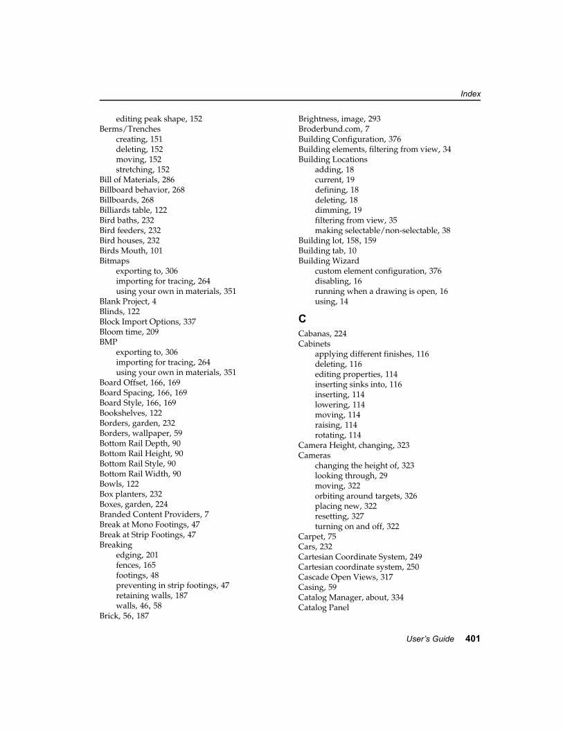
Index
User’s Guide 401
editing peak shape, 152Berms/Trenches
creating, 151deleting, 152moving, 152stretching, 152
Bill of Materials, 286Billboard behavior, 268Billboards, 268Billiards table, 122Bird baths, 232Bird feeders, 232Bird houses, 232Birds Mouth, 101Bitmaps
exporting to, 306importing for tracing, 264using your own in materials, 351
Blank Project, 4Blinds, 122Block Import Options, 337Bloom time, 209BMP
exporting to, 306importing for tracing, 264using your own in materials, 351
Board Offset, 166, 169Board Spacing, 166, 169Board Style, 166, 169Bookshelves, 122Borders, garden, 232Borders, wallpaper, 59Bottom Rail Depth, 90Bottom Rail Height, 90Bottom Rail Style, 90Bottom Rail Width, 90Bowls, 122Box planters, 232Boxes, garden, 224Branded Content Providers, 7Break at Mono Footings, 47Break at Strip Footings, 47Breaking
edging, 201fences, 165footings, 48preventing in strip footings, 47retaining walls, 187walls, 46, 58
Brick, 56, 187
Brightness, image, 293Broderbund.com, 7Building Configuration, 376Building elements, filtering from view, 34Building Locations
adding, 18current, 19defining, 18deleting, 18dimming, 19filtering from view, 35making selectable/non-selectable, 38
Building lot, 158, 159Building tab, 10Building Wizard
custom element configuration, 376disabling, 16running when a drawing is open, 16using, 14
CCabanas, 224Cabinets
applying different finishes, 116deleting, 116editing properties, 114inserting sinks into, 116inserting, 114lowering, 114moving, 114raising, 114rotating, 114
Camera Height, changing, 323Cameras
changing the height of, 323looking through, 29moving, 322orbiting around targets, 326placing new, 322resetting, 327turning on and off, 322
Carpet, 75Cars, 232Cartesian Coordinate System, 249Cartesian coordinate system, 250Cascade Open Views, 317Casing, 59Catalog Manager, about, 334Catalog Panel

Index
402 3D Home Architect® Design Suite Deluxe 6
about, 11displaying/hiding, 311resizing, 311
Catalog Properties, 346Catalogs
adding a group to, 334changing preview display, 339closing, 346creating copies of, 345creating new, 344deleting elements from, 346deleting groups from, 335editing elements, 335importing elements into, 345opening, 346previewing images in, 339renaming groups in, 335saving edited elements from your drawing,
336saving under different name, 345saving, 344, 345viewing properties of, 346
Categoriesadding to catalogs, 334deleting in catalogs, 335renaming in catalogs, 335
Ceiling fans, 128Ceiling Height, 18Ceiling lights, 128Ceiling Openings
curving edges, 79inserting in automatic ceilings, 78inserting in manual ceilings, 78removing, 79resizing, 78
Ceilingsabout, 75applying different materials to, 79by Perimeter, 76by Picking Points, 77by Room, 76curving openings in, 79curving, 77cutting openings in automatic ceilings, 78cutting openings in manual ceilings, 78deleting, 80displaying framing, 32inserting automatically, 22inserting openings in, 78lowering, 77
raising, 77raising/lowering, 77removing openings from, 79resizing openings, 78suspending, 77
Centered text, 275Ceramic Tiles, 75Chair Rails, 59Chairs, 122Chairs, patio, 220Change Display Every _ Steps, 293Changing 233Chests, 122Chimneys
applying materials to, 145editing height, 144inserting, 144
City, 291Click-and-drag insertion method, 22Close Catalog, 346Closed Riser, 181Closing
catalogs, 346Closing projects, 303Coffee tables, 122Cold air returns, 144Collision Control, 241Color
Background (drawing area), 312changing an element’s, 259, 341light sources, 371text, 275, 363toolbar areas, 310toolbars, 310
Color Bleed, 295, 350Colors
applying to the terrain, 150editing an element’s, 341editing material color, 350of plants throughout growing season, 209viewing an element’s, 341
Columnsattaching footings to, 49decorative, 232deleting, 49editing elevation, 49editing size, 49editing type, 49inserting, 48moving, 49

Index
User’s Guide 403
Commanderdisplaying, 248selecting a reference point for actions, 249specifying insertion heights, 248using to rotate elements, 250using when curving elements, 251using, 248
Common plant names, 208Complexity of care (plant), 208Component Display, 338Components, appearance of, 341Computer desks, 122Computers, 122Concrete slabs
applying different materials to, 183creating, 181deleting, 52, 183editing thickness, 52, 183inserting, 51moving, 51, 182reshaping, 51, 182resizing, 51, 182rotating, 52, 182
Concrete walls, drawing, 44Connection, 91Contents, package, 2Context-sensitive menus, 24, 254Contours, showing, 150Convert File From, 337Coordinate icon, displaying/hiding, 248Coordinate system
Cartesian, 250Polar, 250selecting, 249
Coordinates, entering, 250Copies (print), 304Copying
elements, 257walls to create a new story, 55
Copying elements, 257Corner details, 232Corrupted projects, repairing, 300Country, 291Cove Molding, 59Crawlspace foundation, creating, 44Create Elevation View, 329Creating 51, 196Cribs, 122Cropped textures, 351Cross-section, creating, 330
Crown Molding, 59Current View Size, 296Curtains, 122Curving
ceiling opening edges, 79ceilings, 77deck edges, 174deck opening edges, 178retaining walls, 186using the Commander, 251walls, 46, 58
Custom textures, 351Customer Service, 6Customizing
catalogs, 333dimension styles, 361elements, 335light sources, 369line styles, 355materials, 347screen, 309text styles, 361view windows, 315views, 321Wizard configurations, 375
Cut 102Cut an opening around next story, 95Cut Line Spacing, 85Cut Line, editing on stairs, 85Cut Opening
ceiling, 78deck, 177roof, 102
Cut-off textures, 351
DDamaged projects, repairing, 300Date and time, 291day 206Daylight Savings, 291Daylight, turning off, 294Deck Builder Wizard, 172Deck Openings
curving edges, 178inserting, 177removing, 178reshaping, 178resizing, 178
Deck Stairs

Index
404 3D Home Architect® Design Suite Deluxe 6
controlling railing display, 180deleting, 181editing properties, 179editing size, 179inserting, 178moving, 179parts, 179
Deck tool, 173Decks
building with Deck Builder Wizard, 172building with Deck tool, 173changing direction of deck boards, 174changing the railing style, 176controlling display of railings, 177controlling railings on deck stairs, 180creating openings in, 177curving edges, 174curving opening edges, 178deleting, 178displaying footings under posts, 175displaying skirting, 177editing frame construction, 175editing height, 175editing posts, 175inserting a deck floor, 173inserting stairs, 178moving, 174removing openings, 178reshaping openings, 178reshaping, 174resizing openings, 178stretching, 174viewing tutorial, 5
Default save directory, 301Define Floors, 74Delete Element, 346Delete Group
light source library, 371line styles library, 357materials library, 349
Delete Linestyle, 358Delete Material, 349Deleting
accessories, 124appliances, 119berms/trenches, 152building locations, 18cabinets, 116ceiling openings, 79ceilings, 80
columns, 49deck openings, 178deck stairs, 181decks, 178dimension styles from library, 365dimensions, 282doors, 66dormers, 104edging, 202electrical elements, 135electronics, 124elements, 258, 346elevations, 329exterior accessories, 233exterior furniture, 221exterior structures, 225fences, 167filled areas, 197floors, 75footings, 48, 50foundation, 45furniture, 124gates, 169groups from catalogs, 335groups from light source library, 371groups from line styles library, 357groups from materials library, 349groups in View Manager, 316hills, 151HVAC elements, 145irrigation, 236light fixtures, 131light source from library, 371line styles from library, 358linetypes from linetypes library, 359materials from library, 349mono footings, 50openings from roofs, 102outdoor light fixtures, 230paths, 191patio slabs, 183photo boards, 270plants, 206plateaus, 153plumbing fixtures, 141railings, 91ramps, 87retaining walls, 187roofs, 102section views, 331

Index
User’s Guide 405
site boundary, 158skylights, 105slabs, 52slopes, 155sprinklers, 236stairs, 87strip footings, 48text with leader, 277text, 275trace image, 265valleys, 151views in View Manager, 319wall openings, 72walls, 46, 55, 58windows, 70wiring, 137
Depth below ground level, 175Deselecting elements, 24Designer’s View, 28Dim Line Spacing, 279Dimension Offset, 279Dimension Styles
adding, 365changing, 282customizing dimension styles library, 364customizing library, 364deleting from library, 365editing, 365important considerations before editing, 364importing dimension styles from library into
catalog, 367properties, 282, 365saving to library file, 367setting current, 277
Dimensionsabout, 277aligned, 281auto exterior settings, 278auto exterior, 278auto interior, 279changing style, 282deleting, 282displaying/hiding, 36editing an element’s, 258filtering for selection, 40linear, 280moving dimension line, 281scale, 304, 319setting current style, 277stretching, 281
Dimming Percentage, locations, 19Direction, specifying, 250Disabling
Building Wizard, 16templates, 302
Diseases page (Encyclopedia), 215, 216Dishwasher, 118Display All But Framing, 32Display Filter, 34Display Framing, 32Display Highlite, 63, 68Display Left Sidelite, 63, 68Display Lowlite, 68Display Mode, 30Display of graphics, improving, 313Display Right Sidelite, 63, 68Display settings, adjusting, 4Displaying 32, 248
building elements, 34cameras, 322catalog panel, 311Coordinate Icon, 248dimensions, 36electrical wiring, 36framing, 32project trace images, 37selected building elements, 34selected parts on elements, 338terrain, 155text, 36toolbars, 310view tabs, 317
Distance above current location or terrain, 255,342Distance, measuring, 244Distance, specifying, 250Diving board, 224Division, 342Do not use Project Template, 302Doghouses, 224Door mats, 232Door Trim, 59Doors
deleting, 66editing leaf, 64editing shape, 62editing sidelites/highlites, 63editing size, 62editing type, 62flipping the swing, 65

Index
406 3D Home Architect® Design Suite Deluxe 6
flipping, 65inserting, 62lowering, 66moving, 65raising, 66
Dormer Roof, 103Dormers
about, 102creating, 102, 103deleting, 104moving, 103stretching, 104
Down to deck location, 180Down to previous location, 180Down to terrain, 180DPI, 381Dragging method of insertion, 22Drawing from scratch, 4Drawing Grid
displaying, 240setting up, 240turning on and off, 240
Drawings, opening from older versions, 2Dressers, 122Driveways, 190Dryer, 118Drywall, 381Duplicate to Locations, 55, 257Duplicate, 257DXF export, 306
EEdging
breaking, 201changing length, 201changing material, 202cleaning up corners, 200deleting, 202editing height, 202editing width, 202inserting, 200moving, 201rotating, 201stretching, 201
Edit 174Edit City, 291Edit Linestyle, 357Edit Material, 349Edit menu, 24
Editingabout, 253accessing edit commands, 254accessing edit tools, 24appliances, 118berms, 152building locations, 18cabinets, 114catalogs, 334ceilings, 77column elevation, 49column size, 49column type, 49deck stairs, 179decks, 174dimension styles, 364dimensions, 281doors, 62edging, 200electrical elements, 135element properties, 258elements in catalogs, 335exterior accessories, 232exterior furniture, 220exterior structures, 224fences, 165fills, 196floors, 74, 75furnishing elements, 122gates, 168hills, 151HVAC elements, 145leader with text, 276light fixtures, 129, 228light sources, 370line styles, 356linetypes, 359materials, 348mono footing size, 50mono footing type, 50openings, 71path elements, 190patio slabs, 182patterns, 353photo boards, 270plants, 204plumbing fixtures, 140print scale, 319railings, 89ramps, 85

Index
User’s Guide 407
retaining walls, 186roofs, 96, 99screen settings, 309sections, 331site boundary, 158slopes, 154stairs, 82strip footing type, 47text styles, 362text, 274views, 321wall elevation, 45, 57, 186wall height, 45, 57, 186wall openings, 71wall width, 45, 57, 186walls, 44, 54windows, 67
Editing Mode, 23, 254Electrical Elements
applying different colors/materials, 135deleting, 135editing size, 135lowering, 134moving, 135raising, 134wiring, 136
Electrical Wiringchanging line style, 136deleting, 137displaying/hiding, 36inserting, 136making selectable/non-selectable, 40reshaping/stretching, 136
Electronicsapplying different colors/finishes, 123deleting, 124editing properties, 123inserting, 122lowering, 123moving, 122raising, 123rotating, 122
Element Properties, 334Elements
changing display of in preview window, 339changing elevation, 255creating custom, 335deleting from catalogs, 346deleting, 258editing in catalogs, 335
editing properties, 258filtering from view, 34importing 3D Studio files, 336importing into catalogs, 345inserting, 22moving, 254rotating, 255saving edited elements to a catalog, 336
Elevate tool, 255Elevation
accessories, 123appliances, 118cabinets, 114ceilings, 77cut lines, 85doors, 66editing an element’s, 255electrical elements, 134electronics, 123exterior accessories, 232furniture, 123HVAC elements, 145light fixtures, 128photo board, 270plants, 204plumbing fixtures, 140retaining walls, 186wall openings, 72walls, 45, 57windows, 70
Elevation Marksediting properties of, 329moving, 328turning on/off, 328
Elevation Properties, 329Elevations
changing the target of, 329creating custom, 329deleting, 329displaying marks for, 328moving left or right, 328viewing, 328viewing/editing properties, 329
Emissive, 295, 350Enable Ambient Lighting, 294Enable Collision Control, 241Enable Daylight, 294Enable Pre-Selection, 23Encyclopedia
about, 207

Index
408 3D Home Architect® Design Suite Deluxe 6
accessing, 208Diseases page, 215Main page, 208Notebook page, 213Picture page, 214Plant Care Calendar, 210searching for a plant, 208selecting a plant to add to a catalog, 217selecting a plant to view, 208World Map page, 212
Estimatechanging report format, 286filtering, 286generating, 286printing, 286saving, 286specifying name, 287specifying save location, 287turning grid lines off, 286viewing saved estimate, 287
Excavated areas, 152Explicit Height, 180Export Model, 306Export View, 306Exporting
current view, 306custom light sources to library file, 371custom line styles to library file, 358dimension styles to library file, 367materials to library file, 351model, 306text styles to library file, 363to 3DS, 306to BMP, 306to DXF, 306to JPG, 306to TGA, 306to WRL, 306
Extend Stair, 179Extension Below Base, 45, 57, 186, 255Extension Lines, 279Exterior Accessories
changing elevation, 232deleting, 233editing appearance, 233editing size, 232inserting, 232moving, 232rotating, 232
Exterior dimension settings, 278
Exterior Furnitureapplying different colors/materials, 220deleting, 221editing size, 220inserting, 220moving, 220rotating, 220
Exterior Structuresapplying different materials, 225deleting, 225editing size, 225inserting house templates, 224inserting, 224moving, 224rotating, 224
Exterior Wall Tops to Roof, 97Exterior walls
ground floor, 54upper stories, 55
FFabrics, 123Fascia Depth, 101Fascia Distance, 100Fascia type, 101Faucets, 140Fences
breaking, 165deleting, 167editing material, 167editing properties, 165inserting, 164lengthening, 165parts, 165raked, 166shortening, 165stepped, 166stretching, 165
Field of vision, 325File Paths
Projects Directory, 301Templates directory, 302Temporary Directory, 303
Filing cabinets, 122Fills
changing fill material, 197creating, 196deleting, 197moving, 197

Index
User’s Guide 409
reshaping, 196resizing, 196rotating, 197
Filteringbuilding elements for selection, 38, 39building elements from view, 34building locations for selection, 38dimensions for selection, 40dimensions from view, 36display, 34electrical wiring from view, 36elements/locations for selection, 37landscape elements for selection, 39landscape elements from view, 35plants by disease, 215plants by selected criteria, 216project estimate, 286project trace images from view, 37text for selection, 39text from view, 36
Finishing commands, 22Fireplaces, indoor, 144Fireplaces, outdoor, 232Fit To Page, 304Flip Horizontal, 264Flip Opening
doors, 65gates, 168windows, 70
Flip Swingdoors, 65gates, 168
Flip Vertical, 264Flipping
doors swing, 65gate swing, 168gates, 168
Floor Level, 18Floor Locations
adding, 18current, 19defining, 18deleting, 18dimming, 19filtering from view, 35making selectable/non-selectable, 38
Floor openings, inserting, 75Floor plan tracing, 264Floor registers, 144Floor to Ceiling Height, 14
Floorsabout, 74applying different materials to, 46, 75deck, 173deleting, 75displaying framing, 32editing thickness, 75foundation, 44inserting openings in, 75raising/lowering, 74splitting, 74
Flowers, 204Fly Around tool, 326Focal point, moving, 323Fog, 294Font Style, 275, 363Font, 275, 363Footings
breaking, 48deleting mono footings, 50deleting strip footings, 48deleting, 48, 50displaying under deck posts, 175editing size, 47, 50editing type, 47, 50inserting beneath columns, 49lengthening/shortening, 48moving mono footings, 50moving strip footings, 47preventing breaking, 47rotating mono footings, 50stretching strip footings, 48strip footings beneath walls, 47
For 291Format, project estimate, 286Foundation
applying different material to floor, 46deleting, 45drawing walls, 44inserting a slab on grade, 51moving, 44resizing, 44, 45
Fountains, 232Framing
changing, 32displaying, 32editing deck frames, 175hiding, 32roofs, 101
Freezer, 118

Index
410 3D Home Architect® Design Suite Deluxe 6
Furnaces, 144Furniture
applying different materials, 123deleting, 124editing properties, 123inserting, 122lowering, 123moving, 122outdoor, 220raising, 123rotating, 122
GGable End appearance, 96Gable roofs
changing appearance of surfaces under gableends, 96
converting from hip roofs, 96extending gable end walls to roof, 97
Gable type, 101Gap, between trim and wall 59Garages, 224Garbage bins, 122Garden beds, 196Garden borders, 232Garden boxes, raised, 224Gardens, 204Gates
deleting, 169editing properties, 168flipping swing, 168flipping, 168hinge side, 168inserting, 167moving, 168
Gazebos, 224Generate Project Estimate, 286Generate Quantity Report, 286Geometry, editing, 258Global Settings, 291Glossary of Terms, 6, 379, 387Golf Holes, 224Graphics display, improving, 313Graphics print quality, 304Greenhouse, 224Grid
drawing, 240snap, 240
Grid Mesh Spacing, 150
Grid Snap, 240Ground Floor Height above Terrain, 14Ground floor walls, drawing, 54Groups
adding to catalogs, 334adding to light source library, 371adding to line styles library, 357adding to materials library, 348deleting from catalogs, 335deleting from light source library, 371deleting from line styles library, 357deleting from materials library, 349renaming in line styles library, 357renaming in materials library, 349renaming, 335
Growing season (plant), 209Growth, plant, 208Guarantee, 7Guardrails, 87
HHandicap ramp, 82Handle Style, 116Handrail Depth, 90Handrail Height, 90Handrail Style, 90Handrail Width, 90Handrails, 87Hanging planters, 232Hardware Acceleration, 312Hardwood flooring, 75Hatched view, 31Head Height, 18Heater, propane, 232Heating elements, 144Height 205
Camera, 323ceiling, 18deck, 175edging, 202floor, 18head, 18insertion, 342retaining walls, 186specifying insertion height in Commander,
248staircase, 82Target Height, 323wall, 18

Index
User’s Guide 411
window, 18Height (elevation)
appliances, 118cabinets, 114ceilings, 77doors, 66editing an element’s, 255electrical elements, 134exterior accessories, 232HVAC elements, 145light fixtures, 128photo boards, 270plants, 204plumbing fixtures, 140roof, 101wall openings, 72walls, 45, 57windows, 70
HelpE-mail Support, 6Glossary of Terms, 6Online Self-Support, 6online, 6technical, 6Telephone Support, 6Troubleshooting Guide, 6
Hidden Line view, 31Hiding
building elements, 34cameras, 322catalog panel, 311Coordinate Icon, 248dimensions, 36electrical wiring, 36framing, 32project trace images, 37selected building elements, 34terrain, 155text, 36toolbars, 310
Highlitesdoor, 63window, 68
Hillsdeleting, 151editing height, 151editing peak shape, 151moving, 151
Hills, 150Horiz. Distance, 100
Horizontal Separation, mullion, 65, 69Hot tubs, 224House Builder Wizard
custom element configuration, 376disabling, 16running when a drawing is open, 16using, 14
House Templates, 224How to Complete a Project, 5How to Use the Tools, 5Hug Terrain, 51, 166, 182, 190HVAC Elements
deleting, 145editing properties, 145inserting, 144lowering, 145moving, 145raising, 145rotating, 145
Hyperlinks, 343
IIcon, coordinate, 248IES files, importing, 371If 248Ignore next story, 95Image Brightness, 293Importing
3D Studio Files, 336dimension styles into dimension styles li-
brary, 367elements into catalogs, 345IES files, 371light source files, 371line styles into line styles library, 358, 372materials from library file, 352photo boards, 268text files, 274text styles into text styles library, 364
Improving graphics display, 313Include First Post, 90Include Last Post, 90Include Posts, 90Include railing on selected edges, 177Include Railings, 180Include skirting on selected edges, 177Include Walls, 103Included Angle, 251In-ground pools, 224

Index
412 3D Home Architect® Design Suite Deluxe 6
Insertingabout inserting elements, 22accessories, 122air returns, 144appliances, 118cabinets, 114columns, 48concrete slab, 51decks, 172doors, 62driveways, 190edging, 200electrical elements, 134electronics, 122exterior accessories, 232exterior furniture, 220exterior structures, 224exterior walls, 55fences, 164fills, 196floor registers, 144foundation walls, 44furniture, 122gates, 167HVAC elements, 144irrigation, 236landscaping, 193light fixtures, 128, 228mono footings, 49paths, 190patios, 181photo boards, 268, 269plants, 204plumbing fixtures, 140property lines, 158ramps, 82retaining walls, 186scanned home plan, 264sidewalks, 190site boundary, 158sprinklers, 236stairs, 82strip footings, 47text, 274vents, 144walls (exterior), 54walls (foundation), 44walls (interior), 57windows, 66
Insertion 342
Insertion Height, 248Insertion height, 342Insertion Method for line-drawn elements, 22Insertion Point, editing an element’s, 342Installing the software, 3Interior dimension settings, 280Interior dimensions, auto, 279Interior Wall Tops to Roof, 97Interior Walls
dimension setting, 279dimension string, 279
Interior walls, inserting, 57Interiors tab, 10Irrigation
deleting, 236editing height, 236editing spray, 236inserting, 236moving, 236rotating, 236
JJacks, 134JPG
exporting to, 306importing for tracing, 264using your own in materials, 351
Jungle Gyms, 224Justification, text, 275
KKitchen Builder Wizard
custom element configuration, 376using, 110
Kitchen Configuration, 376Kitchen tutorial, 5
LLamps, 128Landing Connection, 83Landing Thickness, 85, 86Landings
adding to ramps, 86adding to stairs, 84
Landscape Lightingediting size, 228inserting, 228moving, 228
Landscape tab, 10

Index
User’s Guide 413
Landscapingdecks, 171, 172edging, 200fences, 163, 164fills, 196filtering elements for selection, 39filtering landscape elements from view, 35garden beds, 196gates, 167hills and valleys, 150inserting furniture, 220inserting house templates, 224inserting structures, 224irrigation, 236paths, 190patios, 171plants, 204plateaus, 152ponds, 196retaining walls, 186sidewalks, 190slopes, 153terrain, 150toolbar, 10viewing tutorial, 5
Latin plant names, 208Latitude, 291Launch House Builder wizard when starting newdrawing, 16Lawn edging, 200Leader arrow style, 276Leader with text, 275Leaf Depth, 64Leaf, door, 64Lean-to roof, 97Learn menu, 5Learn to Use, 5Learning 5Left Justify Text, 275Length 86Lengthening
edging, 201fences, 165paths, 190railings, 91retaining walls, 186strip footings, 48walls, 45, 57
Levels, defining locations for, 18Libraries
Building Configuration, 376Dimension Styles, 364dimension styles, 364Kitchen Configuration, 376Light Source, 370Line Styles, 356Linetypes, 359Materials, 348Patterns, 353Text Styles, 362
Lifetime (plant), 208Light bulbs, changing, 129Light fixtures
changing the look of, 130, 230changing the snap on insertion, 128deleting, 131, 230editing light source, 129, 228editing size, 129, 228inserting outdoors, 228inserting, 128lowering, 128moving, 128, 228raising, 128rotating, 129turning on and off, 130, 229turning on/off, 130, 230
Light posts, 228Light Sources
adding groups to library, 371adding to library, 371customizing library, 370deleting from library, 371deleting groups from library, 371editing color, 371editing in light fixtures, 129, 228editing intensity, 371important considerations before editing, 370saving custom light sources to library file, 371specifying directory, 372
Light switches, 134Lighting preference (plant), 208Lights
customizing light source library, 370interior, 128outdoor, 228path, 228
Lights Directory, 372Line Styles
accessing library, 356adding groups to line styles library, 357

Index
414 3D Home Architect® Design Suite Deluxe 6
adding to library, 357changing for inserted wiring, 136deleting from library, 358deleting groups from library, 357editing in library, 357important considerations when editing, 356importing line styles from library into cata-
log, 358, 372renaming groups in library, 357saving custom line styles to library file, 358
Linear Dimensions, 280Linetypes
adding to linetypes library, 359customizing linetypes library, 359deleting from library, 359editing, 359viewing an element’s, 341
Linoleum, 75Load city template, 292Load IES File, 371Location Dimming, 19Locations
adding, 18current, 19defining, 18deleting, 18filtering from view, 35making selectable/non-selectable, 38
lock, Maintain Aspect Ratio, 350Longitude, 291Look Around tool, 326Look Through, 29Lot lines, 158, 159Lounges, 220Lower Width, 83, 86Lowering
appliances, 118cabinets, 114ceilings, 77decks, 175doors, 66electrical elements, 134elements, 255floors, 74furnishing elements, 123HVAC elements, 145light fixtures, 128outdoor accessories, 232photo boards, 270plants, 204
plumbing fixtures, 140retaining walls, 186wall openings, 72walls, 45, 57windows, 70
Lowlites, 68
MMailboxes, 232Maintain Aspect Ratio, 264, 270, 350Make Continuous, 90Manufacturer, 342Mark Text, 329, 331Marks
elevation, 328section, 331
Materialsadding groups to materials library, 348adding to library, 349applying to terrain, 150changing an element’s, 259, 341customizing materials library, 348deleting from library, 349deleting groups from library, 349editing an element’s, 341editing in library, 349editing surface properties, 295important notes about editing, 348importing from library file, 352properties, 349renaming groups in library, 349rotating on elements, 260, 341saving to library file, 351scale of in rendered views, 350Tile Height, 350Tile Width, 350using textures from outside sources, 350, 351viewing an element’s, 341
Materials Paintbrush, 259Mats, door, 232Max Stringer Spacing, 85Max. Post Spacing, 166Max. Riser Height, 180Maximizing a view window, 318Measure tool, 244Measuring area, 245Medicine cabinets, 122Member Spacing, 101Menu Bar, 10

Index
User’s Guide 415
Menusfor editing, 24, 254
Microwave, 118Min number of vertices per component, 338Mirrors, 122Modify Elements, 24, 254Mono footings
deleting, 50editing size, 50editing type, 50inserting under columns, 49moving, 50rotating, 50
Mono Footings Attached to Columns, 49month 206Month, 291Move Target, 329Move Whole Element
deck, 174fill, 197plateau, 153roof, 99slab, 51, 182
Movingaccessories, 122appliances, 118berms, 152cabinets, 114cameras for 3D views, 322columns, 49deck stairs, 179decks, 174dimension line, 281doors, 65edging, 201electrical elements, 135electronics, 122elements vertically, 255elements, 254elevation target, 329elevations marks, 328exterior accessories, 232exterior furniture, 220exterior structures, 224filled areas, 197foundation, 44furniture, 122gates, 168hills, 151HVAC elements, 145
irrigation, 236leader text, 277light fixtures, 128mono footings, 50outdoor lighting, 228paths, 191photo boards, 269plants, 204plateaus, 153plumbing fixtures, 140ramps, 87roofs, 99section marks, 331site boundary, 158skylights, 104slabs, 51, 182slopes, 155sprinklers, 236stairs, 87strip footings, 47text leader, 276text, 274toolbars, 310trenches, 152valleys, 151wall openings, 71walls, 54windows, 70
Mugs, 122Mulched beds, 196Mullion, 65, 69Multiple text insert, 274
NName generation
about, 339editing the formula, 339using, 339
Name, building location, 18Naming elements, 336New Catalog, 344New Project, 4New View, 316Newel Depth, 91Newel Spacing, 90Newel Style, 91Newel Width, 91Nightstands, 122North arrows, 232

Index
416 3D Home Architect® Design Suite Deluxe 6
Nosing Depth (stairs), 84Nosing, 181Nosing, cabinet, 115Note 242, 344Notebook page (Encyclopedia), 213, 216Notes, in properties dialog, 343Number of copies, 304Number of Floors, 14Number of Steps, 83Number, location, 18
OObelisks, 232Object Snap, 240OBJSNAP, 240Office furniture, 122Offset below roof surface, 97Offset from wall, 60Offset, trim, 59Older versions
opening drawings from, 2uninstalling, 3
Online Help, 6Online Software Help, 6Open Catalog, 346Open View, 316Open, 300Opening
catalogs, 346drawing from older versions, 2sample projects, 300saved estimate, 287saved project, 300saved projects, 300views, 316
Openingscreating in automatic ceilings, 78creating in manual ceilings, 78creating in roofs, 102curving ceiling openings, 79curving deck opening edges, 178deleting from walls, 72deleting, 72dimension string, 278dimension style, 279editing wall opening shapes, 71editing wall opening size, 71inserting in ceilings, 78inserting in decks, 177
inserting in floors, 75inserting in walls, 70lowering in walls, 72moving, 71raising in walls, 72removing from decks, 178reshaping in decks, 178resizing in ceilings, 78resizing in decks, 178
Orientation, element, 256, 340Ortho, 241Orthogonal view mode, 324Outdoor accessories, 232Outdoor fireplaces, 232Outdoor furniture, 220Outdoor structures, 224Outlets, 134Oven, 118Overall dimension string, 278Overall Height, 82Overhang
deck beams, 176deck boards, 176deck joists, 176deck stairs, 181roof, 100
Overhang Drop, 100Override system units, 283, 366
PPackage contents, 2Pad footings
editing size, 50editing type, 50inserting, 49moving, 50
Padsapplying different materials to, 183inserting, 51, 181
Paint, 58Paintbrush, materials, 259Panelling, wood, 58Panning, 30Pans, 122Parallel view mode, 324Part No., 342Path lights, 228Paths
applying different materials, 191

Index
User’s Guide 417
deleting, 191drawing, 190editing length, 190editing thickness, 191editing width, 191moving, 191rotating, 190
Patio furniture, 220Patio umbrellas, 232Patios
applying different materials to, 183creating, 181deleting, 183editing thickness, 183moving, 182reshaping, 182resizing, 182rotating, 182
Patterned properties, 351Patterned view, 31Patterns
customizing library, 353editing on elements, 259editing, 353important notes about editing, 353viewing an element’s, 341
Patterns, element, 341Perspective view mode, 323Perspective, 3D, 29Phone jacks, 134Photo Boards
changing elevation, 270changing to rotating, 270changing to stationary, 270creating transparency in, 270deleting, 270editing size, 270importing, 268inserting, 269moving, 269rotating, 269saving to the catalog, 269
Photo realistic images, 289Pianos, 122Pick and drag insertion method, selecting, 22Pick Points insertion method, selecting, 22Picnic tables, 220Picture page (Encyclopedia), 214Pictures, 122Piers, inserting, 48
Pixel Search Distance, 241Place New Camera, 322Plan view
displaying, 28rendered, 28
Plansimporting for tracing, 264sample, 300
Plant Care Calendar 210Plant Encyclopedia
about, 207accessing, 208care requirements, 208Diseases page, 215growth information, 208lighting preferences, 208Main page, 208Notebook page, 213Picture page, 214Plant Care Calendar, 210searching for a plant, 208selecting a plant to add to a catalog, 217selecting a plant to view, 208temperature preferences, 208water requirements, 208World Map page, 212
Plant Growth Over Time, 206Plant Seasonal Change, 206Planters, 232Planting age, 205Plants
adding to catalog from Encyclopedia, 217applying seasonal change, 206care calendar, 210changing age, 205changing elevation, 204deleting, 206diseases, 215, 216editing appearance in 2D plan view, 204editing size, 205Encyclopedia, 207filtering by selected criteria, 216forcing custom size, 205inserting, 204life expectancy, 208moving, 204seeing growth over time, 206soil requirements, 208usages, 208zone information, 208

Index
418 3D Home Architect® Design Suite Deluxe 6
Plateauscreating, 152deleting, 153editing height, 153editing peak shape, 153moving, 153reshaping, 153stretching, 153
Plates, 122Playgrounds, 224Playhouses, 224Plumb fascia, 101Plumb soffit, 101Plumbing Fixtures
applying different colors/finishes, 141deleting, 141editing size, 140inserting, 140lowering, 140moving, 140raising, 140rotating, 140
Pointer tool, 23, 254Polar Coordinate System, 249, 250Ponds, 196Pool slide, 224Pool table, 122Pools, 224Porch roof, 97Position Offset, 83, 86Position, materials on elements, 260Post Depth, 90Post edging, 200Post Extension, 166Post Height, 90Post Position, 90Post Rotation, 90, 166Post Spacing, 90Post Style, 90Post Width, 90, 166Posts
deck, 175deleting, 49editing elevation, 49editing size, 49editing type, 49fence, 166general, 48inserting, 48moving, 49
railings, 90Pot lights, 128Pots, 122Precision for units of measure, 244Precision, 344Pre-Selection, enabling, 23Preset Cameras, 324Preventing 16Preview, element, 339Previous versions
opening drawings from, 2uninstalling, 3
Price, 342Pricing, editing, 287Print Scale, editing, 319Print Setup, 304Print to Scale, 304Print, 303Printing
area/perimeter calculations, 245drawings, 303editing the print scale, 319project estimate, 286quality, 304to scale, 304
Program Basics, 5Program Help, 6Project Estimate
changing report format, 286filtering, 286generating, 286printing, 286saving, 286specifying name, 287specifying save location, 287turning grid lines off, 286viewing saved estimate, 287
Project Trace Imagedeleting, 265displaying/hiding, 37importing, 264making selectable/non-selectable, 40resizing, 264
Projections dimension string, 278Projects
opening, 300repairing, 300saving as templates, 301saving, 301
Projects Directory, 301
Index
User’s Guide 419
Propane heater, 232Properties
accessories, 123appearance, 341appliances, 118, 123berms, 152cabinets, 114columns, 49deck posts, 175deck railings, 176deck stairs, 179decks, 175dimensions, 282doors, 62, 63, 64edging, 202editing element properties in catalogs, 339editing, 346electrical elements, 135electronics, 123element composition, 258element geometry, 258element size, 258element, 258, 346elevation, 329exterior accessories, 232exterior furniture, 220exterior structures, 225fence, 165floors, 75furniture, 123gate, 168hills, 151HVAC elements, 145light fixtures, 129, 228mono footings, 50of catalogs, 346openings, 71path elements, 191photo boards, 270plants, 204plateaus, 153plumbing fixtures, 140railings, 89ramps, 85retaining walls, 186roofs, 100Section Properties, 331skylights, 105slopes, 155stairs, 83, 84
stairs/ramps, 82strip footings, 47viewing an element’s, 334viewing, 346wall openings, 71windows, 67
Property lines, 158, 159
QQuality, rendering, 293Quantity page, 342Quantity Reports
generating, 286
RRadius, 251Radius, nosing curve, 115Rafters, 101, 384Rail edging, 200Railings
by Picking Points, 89by picking points, 89changing a deck’s railings, 176deleting, 91editing properties, 89horizontal, 89inserting on a floor, 89inserting on stairs automatically, 87inserting, 87on deck stairs, 180on decks, 177on stair center, 88on stair left, 88on stair right, 88parts, 89rotating, 91stretching, 91
Rails (edging), 200Raised garden boxes, 224Raised Heel, 101Raising
appliances, 118cabinets, 114ceilings, 77decks, 175doors, 66electrical elements, 134elements, 255floors, 74

Index
420 3D Home Architect® Design Suite Deluxe 6
furnishing elements, 123HVAC elements, 145light fixtures, 128outdoor accessories, 232photo boards, 270plants, 204plumbing fixtures, 140retaining walls, 186wall openings, 72walls, 45, 57windows, 70
Raked fascia, 101Raked fence, 166Raked soffit, 101Raking walls, 97Ramp Thickness, 85Ramps
adding landings to, 86adding segments to, 86changing a segment type, 87deleting segments from, 87deleting, 87editing layout, 86editing properties, 85editing size properties, 82inserting, 82moving, 87rotating, 87
Range, 118Recently used file list, 300Redo, 254Reference point icon, 248Reference point, commander, 249Refreshing the view during rendering, 293Refrigerator, 118Registering the program, 4Registers, 144Rename Group
line styles library, 357materials library, 349
Renaminggroups in View Manager, 316groups, 335View Windows, 318
Render 3DTrueView, 292Render to File, 295, 296Rendered 2D plan view, 28Rendered Outline view, 31Rendered properties, 350Rendered view, 31
Renderingabout, 290adjusting image brightness, 293changing refresh rate during lighting calcula-
tions, 293changing refresh rate, 293creating a 3DTrueView rendering, 292creating fog effect, 294creating smoke effect, 294enabling ambient lighting, 294saving multiple image files, 296setting quality, 293setting the viewpoint, 290setting up scene, 290specifying image size, 296turning daylight off, 294using antialiasing, 294
Repair Project, 300Report filter, 286Report format, estimate, 286Report, material, 286Requirements, system, 2Reset Camera, 327Reshaping
deck openings, 178decks, 174filled areas, 196paths, 190plateaus, 153slabs, 51, 182wiring segments, 136
Resizingcatalog panel, 311ceiling openings, 78deck openings, 178exterior wall layout, 54, 56fills, 196foundation, 44, 45Project Trace Image, 264slabs, 51, 182
Resolution, setting, 4Restoring previous view window arrangement,318Retaining Walls
applying different finishes to, 187breaking, 187curving, 186definition, 384deleting, 187drawing, 186
Index
User’s Guide 421
editing properties, 186lengthening, 186lengthening/shortening, 186rotating, 186shortening, 186
Right Justify Text, 275Right-click menus
accessing, 24, 254Riser Angle, 84Riser Height, 82, 180Riser Maximum, 83Roof Openings
removing, 102Roof tiles, 101Roofs
applying different materials to, 101by Perimeter, 94by Picking Points, 94changing appearance of surfaces under gable
ends, 96changing the way a lower-story roof is creat-
ed, 95changing the way lower-story roofs are creat-
ed, 95converting hip to gable, 96cutting openings in, 102deleting, 102displaying framing, 32editing height, 101editing shape, 100editing size, 100extending gable end walls to roof, 97inserting automatically, 94inserting dormers, 102inserting skylights, 104moving, 99porch, 97removing openings from, 102rotating, 100selecting for editing, 99shed, 97solution types, 95specifying framing details, 101stretching, 99
Rotatingaccessories, 122appliances, 118cabinets, 114decks, 174edging, 201
electronics, 122elements, 255, 256, 340exterior accessories, 232exterior furniture, 220exterior structures, 224filled areas, 197furniture, 122HVAC elements, 145irrigation, 236light fixtures, 129materials on elements, 260, 341mono footings, 50paths, 190photo boards, 269plumbing fixtures, 140railings, 91ramps, 87retaining walls, 186roofs, 100skylights, 104slabs, 52, 182sprinklers, 236stairs, 87text, 274using the Commander, 250walls, 45, 57
Rugs, 122
SSamples, 300Sandboxes, 224Satisfaction Guaranteed, 7Save All, 301Save As, 301Save Catalog As, 345Save Catalog, 344, 345Save city template, 292Save directory, default, 301Save Element to Catalog, 336Save location, 3DTrueView image, 295Save location, project estimate, 287Save, 301Saved Project, 300Saving
3DTrueView renderings, 295automatically, 301catalogs, 345cities, 292custom materials to library file, 351

Index
422 3D Home Architect® Design Suite Deluxe 6
dimension styles to library file, 367multiple rendered images in same project,
296photo boards to the catalog, 269project estimate, 286projects as templates, 301projects, 301text styles to the library file, 363
Scaledrawing, 316editing, 319Fit to Page, 304light source intensity, 371of dimensions, 304, 319of materials, 350of text, 304, 319of views, 304, 319printing to, 304printouts, 319
Scaling project trace images, 264Scanned floor plans, importing, 264Scene setup for rendering, 290Sconces, 128Screen area size, setting, 4Screen layout, 9Screen settings, 309Screen tips, disabling, 23Screened rooms, 224Season Change, 206Season Color Diagram, 209Seat, 101Second Floor, adding, 55Secondary Post Position, 166Section Marks On/Off, 331Section Properties, 331Section Views
creating, 330deleting, 331editing properties, 331editing, 331turning section marks on/off, 331viewing, 330
Select 36, 37Select All, 23, 39Select button (3D Studio file), 338Select button (Encyclopedia), 217Select elements on current location only while inplan view, 24Select None, 39Select Previous, 23
Select/Edit, 23, 254Selectability
of building elements, 38, 39of building locations, 38of dimensions, 40of electrical wiring, 40of elements in 2D plan view, 24of project trace images, 40of text, 39specifying, 37
Selectingdisabling pre-selection, 23elements, 23roofs, 99
Selection Filterabout, 37filtering building elements, 38, 39filtering building locations, 38filtering dimensions, 40filtering electrical wiring, 40filtering landscape elements, 39filtering project trace images, 40filtering text, 39
Selection mode, 23, 254Set Current Time, 291Set Decking Direction, 174Settings, saving in a template, 301Shape
door, 63Shed roof, 97Sheds, 224Shelves
inserting, 122showing in cabinets, 115
Shingles, 101Shortcut menus, 24, 254Shortening
edging, 201fences, 165paths, 190railings, 91retaining walls, 186strip footings, 48walls, 45, 57
Show Backsplash, 115Show contours, 150Show Coordinate Icon, 248Show Counter, 115Show Cut Lines, 85Show Grid (estimate), 286

Index
User’s Guide 423
Show Grid, 245Show Handle, 116Show Nosing, 115Show Riser, 83Show Shelves, 115Show trunk in plan, 205Shower curtains, 122Showers, 140Shrubs, 204Shutters, 122Side Offset, 91Sidelites
door, 63window, 68
Sidewalks, 190Siding, 56Simplify, 338Simplifying 338Sinks, 116, 140Site Boundary, 158, 159Size
editing an element’s, 258printouts, 319property page, 340rendered image, 296
Skirting, deck, 177Skylights
deleting, 105editing properties, 105inserting, 104moving, 104rotating, 104
Slabsapplying different materials to, 183creating, 181deleting, 52, 183editing thickness, 52, 183inserting on grade, 51moving, 51, 182reshaping, 51, 182resizing, 51, 182rotating, 52, 182
Slide tool, 326Slope Type, 100Slope Value, 100Slope, ramp, 86Slopes
creating, 153deleting, 155editing angle, 155
editing height, 155moving, 155stretching, 154
Smoke detectors, 134Smoke, 294Snap Angle, 241Snap Edge, 342Snap Light To, 128Snapping
at defined angles, 241orthogonal, 241to drawing grid, 240to objects, 240
Sofas, 122Soffit type, 101Soil beds, 196Soil requirements (plant), 208Solution Type (roofs) 95Spacing
deck boards, 176posts along beam, 175
Specify Framing, 32, 101Specular, 295, 350Spinning in 3D view, 326Splitting floors, 74Spray properties, sprinkler, 236Sprinklers
deleting, 236editing height, 236editing spray properties, 236inserting, 236moving, 236rotating, 236
Square footage, measuring, 245Stairs
adding flights to, 84adding landings to, 84adding to deck, 178changing a segment type, 84deleting segments from, 84deleting, 87editing cut line, 85editing details, 84editing layout, 83editing size properties, 82inserting railings on, 87inserting, 82moving, 87parts, 82rotating, 87

Index
424 3D Home Architect® Design Suite Deluxe 6
Standard Report Form, 286Start a New Project, 4Starting from scratch, 4Starting the program, 4Startup dialog
about, 4disabling, 4
Stationary photo board, 268Status Bar
about, 12displaying, 312hiding, 312
Stepped fence, 166Stone, 56, 187Storage sheds, 224Stories
adding, 55defining locations for, 18
Stretchingberms, 152decks, 174dimensions, 281dormers, 104edging, 201exterior wall layout, 54, 56fences, 165fills, 196foundation wall layout, 44paths, 190plateaus, 153railings, 91retaining walls, 186roofs, 99section marks, 331slopes, 154strip footings, 48text leader, 276trenches, 152walls, 44, 45, 54, 56, 57wiring segments, 136
Stringer Side Offset, 84Stringer Thickness, 85Stringer Waste, 84Strip footings
breaking, 48deleting, 48editing size, 47editing type, 47lengthening/shortening, 48moving/stretching, 47
preventing breaking, 47stretching, 48
Strip Footings Attached to Walls, 47Structures, exterior, 224Sundials, 232Supplier, 342Support height above main roof, 103Support Height, 101Support, technical, 6Surface Properties, materials, 295Survey, site, 158, 159Suspended Ceiling, 77, 384Swing Type, 63Swing, flipping, 65Swings, 224Switches, 134System Requirements, 2
TTables, 122Tables, patio, 220Tables, picnic, 220Tabs
changing color of, 310disabling tabbed toolbars, 310displaying toolbars in 310hiding, 310showing, 310toolbar, 10view tabs, 317
Targetchanging the height of, 323moving an elevation’s, 329moving, 323orbiting around the camera, 326
Target Height, changing, 323Technical Support, 6Telephones, 122Television outlets, 134Televisions, 122Temperature preferences (plant), 208Template
path to Templates directory, 302saving a project as, 301setting default, 302starting drawings without, 302
Templates, house, 224Temporary Directory, 303Tennis courts, 224

Index
User’s Guide 425
Terrainapplying a texture and color, 150base level, 150hugging, 51, 182, 190settings, 150toolbar, 11turning on/off, 155
Terrain Base Level, 150Terrain tab, 10Text
adding to drawing, 274changing justification, 275changing the style of inserted text, 275deleting, 275displaying/hiding, 36editing content, 274editing leader text, 277filtering for selection, 39importing text files, 274moving, 274rotating, 274scale, 304, 319with leader, 275
Text Color, 275, 363Text Height, 275, 363Text Styles
changing the style of existing text, 275customizing text styles library, 362editing in elevation marks, 329editing in section marks, 331elevation marks, 329important considerations when editing, 362importing text styles from library into cata-
log, 364saving to library file, 363
Text with Leaderadding, 275changing leader arrow, 276deleting, 277editing text, 277moving the text, 277moving/stretching, 276
Texturesapplied to elements, 341applying different textures to elements, 259applying to the terrain, 150appropriate sizing for, 351cropped, 351cut-off, 351specifying location of directory, 352
using different, 350using from outside sources, 351viewing an element’s, 341
Textures Directory, 352TGA
exporting to, 306importing for tracing, 264using your own in materials, 351
Thermostats, 134Thickness
foundation slab, 52patio slab, 183roof, 100
Tile Height, 350Tile Horizontally, 350Tile Open Views, 317Tile Vertically, 350Tile Width, 350Tiles, 75Time of day, 291Time Zone, 291Title 10Title bar, 10Toaster, 118Toe Depth, 115Toe Height, 116Toilet paper dispenser, 122Toilets, 140Toolbars
Basic View Control, 11Building, 10changing color of toolbar areas, 310changing the background color of, 310displaying in non-tabbed format, 310displaying in tabs 310hiding, 310Interiors, 10Landscape, 10moving, 310showing, 310tabbed, 10terrain, 11Zoom and Navigate, 11
Tooltips on elements, 23Topography, recreating, 149Total Steps, 82Towel accessories, 122Tracing imported floor plans, 264Trampolines, 224Transfer

Index
426 3D Home Architect® Design Suite Deluxe 6
dimension styles, 367line styles, 358materials, 351, 352text styles, 363
Transomdoor lites, 65window lites, 69
Transparency, 295, 350Transparency, in photo boards, 270Trash Compactor, 118Tread Run, 83Tread Thickness, 84Trees, 204Trellises, 232Trenches
creating, 151deleting, 152moving, 152stretching, 152
Trim basepoint, 60Trim, adding to walls, 59Troubleshooting Guide, 6Trunk Diameter, 205Trusses, 101, 385Tubs, 140Tutorials
Advanced Roofs, 5Becoming a Power User, 5Catalogs, 5Customizing Elements, 5Importing Your Own Images, 5Multiple Floors/Split Levels, 5Visualizing in 3D, 5
Tutorials, 5
UUmbrella, patio, 232Undo, 254Uninstalling previous version, 3Units of Measure, 244, 344Upper Offset, 83, 86Upper Width, 83, 86Usage (plant), 208Use Solid Color, 350Use Texture, 350Using 14
VValleys
deleting, 151inserting, 150moving, 151
Vegetable garden boxes, 224Vents, 144Vert. Distance, 100Vertical Separation, mullion, 65, 69View Filter
about, 33filtering building elements from view, 34filtering dimensions from view, 36filtering landscape elements, 35filtering locations from view, 35filtering text from view, 36
View Manageraccessing, 316adding groups to, 316adding new views to, 316deleting groups in, 316deleting views in, 319renaming groups, 316
View ModeParallel, 324Perspective, 323
View Project Estimate, 287View Sample Plans, 300View Tabs
turning on/off, 317View Windows
cascading, 317creating new, 316creating, 316deleting, 319managing, 316maximizing, 318renaming, 318restoring the previous arrangement, 318switching between, 317
Viewing2D Designer’s View, 282D Plan View, 28cameras, 322elevations, 328framing, 32in 3D, 29managing views, 316section views, 330switching between view windows, 317
Viewing Angleincreasing/decreasing, 325

Index
User’s Guide 427
selecting a preset camera angle, 324Viewing Field, 325Viewpoint in 3DTrueView renderings, 290Viewpoint, 3D view, 322Views
exporting, 306opening, 316
Volleyball courts, 224VRML export, 306
WWainscoting, 59Walk Around tool, 326Wall air returns, 144Wall Height, 18, 45, 57, 186Wall lights, 128Wall Openings
deleting, 72editing shape, 71editing size, 71inserting, 70lowering, 72moving, 71raising, 72
Wallpaper borders, 59Wallpaper, 58Walls
adding trim to, 59applying different finishes to, 56attaching strip footings to, 47breaking, 46, 58concrete, 44curving, 46, 58deleting openings, 72deleting, 46, 55, 58displayed framing, 32editing elevation, 45, 57, 186editing height, 45, 57, 186editing opening shapes, 71editing properties, 45, 57editing width, 45, 57, 186extending to gable ends, 97exterior, 54foundation, 44ground floor exterior, 54inserting openings in, 70interior, 57lengthening, 57lengthening/shortening, 45, 57
moving openings, 71moving, 54painting, 58retaining, 186rotating, 45, 57second floor exterior, 55shortening, 57stretching the layout, 54, 56stretching, 44, 45, 54, 56wallpapering, 58
Washer, 118Water heaters, 144Water requirements (plant), 208Weather vanes, 232Width, wall, 45, 57, 186Windchimes, 232Windmills, 232Window Height, 67Window treatments, 122Window Trim, 59Window Width, 67Windows
deleting, 70editing details, 69editing lites, 68editing size, 67editing type, 67flipping, 70inserting, 66lowering, 70moving, 70raising, 70skylights, 104
Wireframe view, 31Wiring
changing line style, 136deleting, 137displaying/hiding, 36inserting, 136making selectable/non-selectable, 40reshaping, 136stretching, 136
WizardsDeck Builder, 172House Builder, 14, 16Kitchen Builder 110
Wood flooring, 75Wood panelling, 58Wood stoves, 144World Map page, 212, 216

Index
428 3D Home Architect® Design Suite Deluxe 6
WRL export, 306
XX, Y, Z coordinates, 250
ZZ 250Zone (plant), 208Zoom and Navigate toolbar, 11Zoom Realtime, 30Zoom to Fit, 30Zoom Window, 30Zooming 30Zooming in and out, 30