3d numerical modeling of free surface flow with air ... · 3d numerical modeling of free surface...
TRANSCRIPT
1
3D numerical modeling of free surface flow with air
entrainment. Complementary spillway of Salamonde.
Extended Abstract
Eddy Nelson dos Reis Pereira ([email protected])
Supervisor António Alberto do Nascimento Pinheiro
June 2016

2
1
1. Introduction
CFD (Computational Fluid Dynamics) models are very useful for the majority of the industry, as they
allow to develop alternative solutions in a faster and economical way. These models can also significantly
reduce the use of physical models, and avoid some scale effects that physical models cannot overcome.
From this point of view, CFD models may be regarded as a complementary tool for a more efficient
design procedure.
A key advantage of using CFDs is the possibility of economically varying the geometry and other
features for a given prototype. This may improve the solutions that, in the end, may be tested in physical
models, saving time and money.
In rapidly varied regimes occurring in complex geometry prototypes, 1-D and 2-D numerical models are
limited for the representation of flow characteristics, compared to the potential of CFD 3-D models
that allow to simulate, with high precision, turbulence effects associated for this type of regime.
2. Objectives
This dissertation intends to assess the numerical capabilities of air entrainment and sediment transport
simulation of the commercial CFD FLOW-3D® applied to the complementary spillway of Salamonde dam,
departing from the research developed by Silva (2013) and using physical model results, respectively.
Additionally, FLOW-3D® is also used to study alternative outlet structures for the spillway, analyzing the
corresponding jets and the respective scour holes.
3. Fundamental theory
3.1. Air entrainment and scale effects
According to Chanson (2001), scale effect is the discrepancy between model and prototype resulting when
one or more dimensionless parameters have different values in the model and prototype.
The correct physical modeling of a two-phase flow in a physical model requires a correct
representation of the similarity laws.
The similitude of the behavior of a two-phase flow between two systems is guaranteed if both match
the same Morton number. However, the Morton similarity between two systems guarantees correct
reproduction of the air bubbles, but does not characterize the problem of shear layer for a free jet.
The air entrainment in a free surface mainly results from the development of small turbulent structures
in the air-water free surface, which have the capacity to trap air carrying it to the core of the flow.
The entrance of air in the flow, through the free surface, is defined by an equilibrium condition between the
turbulent kinetic energy per unit volume (turbulent energy uplift), Pt, and energy stabilizing forces, Pd.
Numerically, the scalar method of the air entrainment model allows the volume entrance of air to
the mixture, through the following expression:
{
𝛿𝑉 = 0, 𝑖𝑓 𝑃𝑇 < 𝑃𝑑
𝛿𝑉 = 𝐶𝑎𝑖𝑟𝐴𝑠 [2 (𝑃𝑇 − 𝑃𝑑)
𝜌𝑚𝑖𝑥]
12
, 𝑖𝑓 𝑃𝑇 > 𝑃𝐷 (3.1)
where, 𝜌𝑚𝑖𝑥 define the density of the flow mixture, which is equal to the density of water, 𝜌𝑤, when only
scalar method is selected.
2
The definition of the mixture density is determined by the implementation of density evaluation method
through the following expression:
𝜌𝑚𝑖𝑥 = 𝐹𝜌𝑤 + (1 − 𝐹)𝜌𝑎𝑖𝑟 (3.2)
where F represents the volumetric fraction and 𝜌𝑎𝑖𝑟 the air density.
The density evaluation method considers the bulking increase in the mixture, modifying the flow behaviour,
when the entrained air is higher than 1-3%.
The numerical implementation of the drift-flux method considers the possibility of the air being entrained as
a cloud of tiny bubbles, which not only bulk the fluid but also affect the flow in two additional ways: by adding
relative velocity between the air and water, and by adding bubble form drag and inter-bubble wake drag
(Hirt, 2007).
3.2. Flow-3D sediment scour formulation
FLOW-3D® sediment scour model includes several numerical formulations that can describes sediment
transport behaviour, namely: drifting/settling, suspension, lifting, bed load and packing faction processes.
Bed load (rolling, sliding and saltating) and suspension motions are numerically solved separately
through the numerical definition of the saltation height layer, 𝛿𝑖, and packing fraction (Flow Science, 2014;
Van Rijn, 1984). Fernandez Luque, in Van Rijn (1984), measured and computed saltation characteristics for
three equivalent roughness of Nikuradse cases, 𝑘𝑠/𝑑50, and concluded that the saltation layer increase for
smaller values. Van Rijn (1984) also defined that the saltation height layer is equivalent to the thickness of
the bed load layer:
𝛿𝑖
𝑑50= 0.3𝑑∗,𝑖
0.7 (𝜃𝑖
𝜃𝑐𝑟− 1)
0.5
(3.3)
The bed load layer concentration (also called by packing fraction), 𝑓𝑏, is defined by the following expression:
𝑓𝑏,𝑖 = 0.18𝑓𝑠,𝑐𝑟𝑖𝑡
𝑑∗ (
𝜃𝑖
𝜃𝑐𝑟− 1) (3.4)
where, 𝑓𝑠,𝑐𝑟𝑖𝑡, is the maximum bed load concentration, called by maximum packing fraction in FLOW-3D®,
𝑑∗, is the dimensionless diameter, 𝜃𝑐𝑟, is the dimensionless Shields parameter, and 𝜃𝑖 is the Shields
effectiveness parameter.
The Shields parameter can be computed by Soulsby-Whitehouse (1997) formulation or manually by the
user. Slope and hiding-exposure formulations can also be optionally implemented to the numerical
Shields formulation.
In FLOW-3D®, settling, lifting, and bed load velocity motions are defined, respectively, by the Soulsby
(1997), Winterwerp (1992) and Meyer-Peter-Müller (1948) formulations, through the following expressions:
𝑢𝑠𝑒𝑡𝑡𝑙𝑖𝑛𝑔,𝑖 =𝜐𝑓
𝑑𝑖
[(10.362 + 1.049𝑑∗3)0.5 − 10.36] (3.5)
𝑢𝑙𝑖𝑓𝑡,𝑖 = 𝛼𝑛𝑠𝑑∗,𝑖0.3(𝜃𝑖 − 𝜃𝑐𝑟)1.5√𝑔 𝑑𝑖(𝑠 − 1) (3.6)
𝑢𝑏𝑒𝑑𝑙𝑜𝑎𝑑,𝑖 =𝑞𝑏,𝑖
𝛿𝑖𝑓𝑏,𝑖
(3.7) 𝜙𝑖 = 𝛽𝑖(𝜃𝑖 − 𝜃𝑐𝑟,𝑖)1/3
𝑞𝑏,𝑖 = 𝜙𝑖 [𝑔 (𝜌𝑠,𝑖 − 𝜌𝑓
𝜌𝑓) 𝑑𝑖
3]
1/2
3
in which 𝛼 and 𝛽 are the lift and bed load calibration factors, respectively, and 𝜙𝑖 and 𝑞𝑏,𝑖 are the
dimensionless and volumetric bedload transport rate.
4. Case study
The present case study results from Silva (2013) CFD study of the complementary spillway of Salamonde
dam, which analysed FLOW-3D® model capacities to simulate several flow discharges into this bended
complex geometry.
The flow characteristics for the original spillway design discharge (1233m3/s) are evaluated at the present
case study, without and with implementing the air entrainment model.
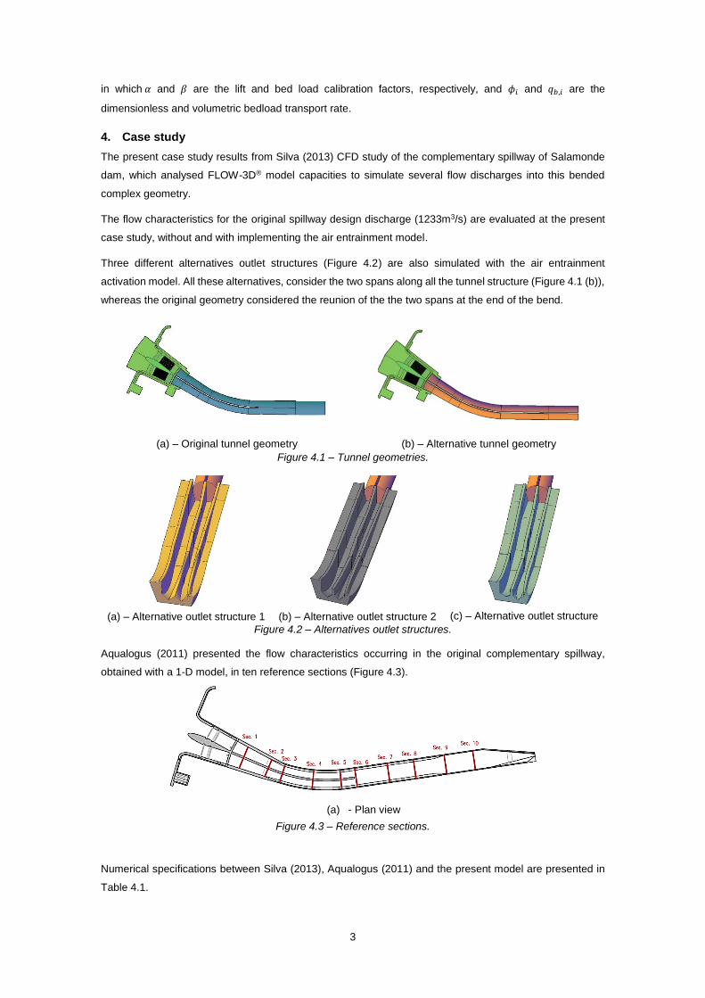
Three different alternatives outlet structures (Figure 4.2) are also simulated with the air entrainment
activation model. All these alternatives, consider the two spans along all the tunnel structure (Figure 4.1 (b)),
whereas the original geometry considered the reunion of the the two spans at the end of the bend.
(a) – Original tunnel geometry (b) – Alternative tunnel geometry
Figure 4.1 – Tunnel geometries.
(a) – Alternative outlet structure 1 (b) – Alternative outlet structure 2 (c) – Alternative outlet structure
3 Figure 4.2 – Alternatives outlet structures.
Aqualogus (2011) presented the flow characteristics occurring in the original complementary spillway,
obtained with a 1-D model, in ten reference sections (Figure 4.3).
(a) - Plan view
Figure 4.3 – Reference sections.
Numerical specifications between Silva (2013), Aqualogus (2011) and the present model are presented in
Table 4.1.

4
Table 4.1 - Numerical specifications that were applied to the studies of the complementary spillway of Salamonde dam.
Model Time results (s) Numerical model Cell Size (m) TLEN (m)
Aqualogus (2011) - 1-D - -
Silva (2013) 70 3-D (FLOW-3D®) 0,25 0,4
Present study 150 3-D (FLOW-3D®) 0,50 Dynamically computed
Scour holes are modelled for a plunge pool with an elevation of 209,30 m and with a flat sediment bottom
composed by one layer, characterized with grains size of 1,10 m. Physical processes of a scour hole
development by water jet impingement differ significantly to bed load transport processes. Meyer-Peter-
Müller numerical formulation is not adjusted to the grain size case and does not represent appropriately
scour hole processes. Thus, bed load transport numerical formulation was not activated.
5. Air entrainment results
5.1. Flow discharge
In order to assess the influence of turbulence models and air entrainment formulations into the water-
air flow discharge capacity, several simulations were performed (Table 5.1).
Table 5.1 – Air entrainment simulation tests.
Turbulence Air entrainment formulations
Model
TLEN
(m) Scalar
Density
evaluation Drift-Flux
Adiabatic
bubbles Surface tension
SV 1(1) RNG
k-e D.Compt2 x x x - -
SV 2.1 RNG
k-e 0,5 x x x - -
SV 2.2 RNG
k-e D.Compt x x x - -
SV 3 RNG
k-e D.Compt x x x x -
SV 4 RNG
k-e D.Compt x x x x 0,073
SV 5 LES x x x x 0,073
Water-air flow discharge capacities, and original and alternative spillways rating curves for SV4 parameters
simulation are presented on the Table 5.2 and Figure 5.1, respectively.
Table 5.2 – Averaged water-air flow discharge capacity in a control section in the downstream limit of
the tunnel structure.
Air entrained volume flow rate (m3/s)
Liquid volume flow rate (m3/s)
SV1 128 1306
SV2.1 255 1427
SV2.2 248 1418
SV3 128 1302
SV4 127 1302
SV5 5,0 1185
Silva (2013) 0 1206
Aqualogus (2011)
- 1233
Figure 5.1 – Original and alternative tunnel rating curve.
(1) – Cell size: 1.00 m (2) - D. Compt: Dynamically Computed
5
It is important to notice that all the two-phase flow simulations over predicted more or less significantly the
flow discharge capacity (SV5 LES simulation is an exception), in comparison the Aqualogus (2011) project
design and Silva (2013) numerical model.
Silva (2013) results underestimated the flow discharge in 2,2% in comparison to the project design. The
numerical model is reproduced from the prototype scale, and it is observed that the definition of superficial
tension has a residual influence on the air entrainment. It is also important to notice that the activation of the
adiabatic bubbles have a major importance to control the effect of the pressure gradient for extremely
accelerated regime.
An increase of +8% for the discharge capacity was observed for the SV4 simulation, in comparison to Silva
(2013) results. Thus, SV4 parameters were adopted to proceed for the validation of the main flow
characteristics results.
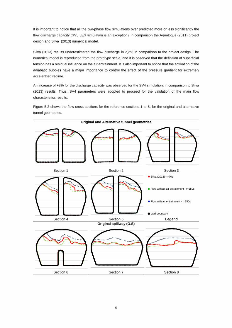
Figure 5.2 shows the flow cross sections for the reference sections 1 to 8, for the original and alternative
tunnel geometries.
Original and Alternative tunnel geometries
Section 1 Section 2 Section 3
Section 4 Section 5 Legend
Original spillway (O.S)
Section 6 Section 7 Section 8
243
245
247
249
251
253
Co
ta d
a s
up
. liv
re (
m)
235
237
239
241
243
245
Co
ta d
a s
up
. liv
re (
m)
234
236
238
240
242
244
Co
ta d
a s
up
. liv
re (
m)
233
235
237
239
241
243
Cota
da s
up. liv
re (
m)
231
233
235
237
239
241
Cota
da s
up. liv
re (
m)
Silva (2013)- t=70s
Flow without air entrainment - t=150s
Flow with air entrainment - t=150s
Wall boundary
230
232
234
236
238
240
Co
ta d
a s
up
. livre
(m
)
228
230
232
234
236
238
Co
ta d
a s
up
. liv
re (
m)
227
229
231
233
235
237
Co
ta d
a s
up
. liv
re (
m)
6
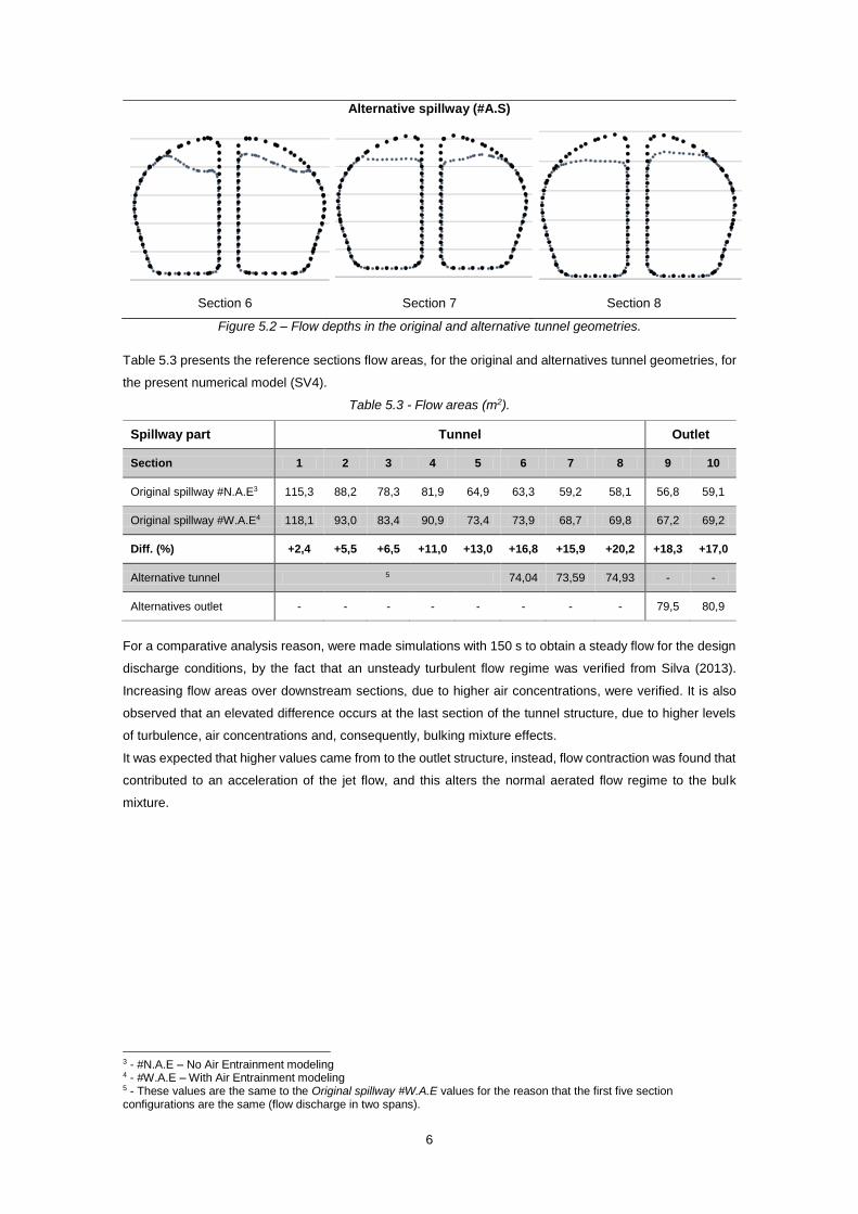
Alternative spillway (#A.S)
Section 6 Section 7 Section 8
Figure 5.2 – Flow depths in the original and alternative tunnel geometries.
Table 5.3 presents the reference sections flow areas, for the original and alternatives tunnel geometries, for
the present numerical model (SV4).
Table 5.3 - Flow areas (m2).
Spillway part Tunnel Outlet
Section 1 2 3 4 5 6 7 8 9 10
Original spillway #N.A.E3 115,3 88,2 78,3 81,9 64,9 63,3 59,2 58,1 56,8 59,1
Original spillway #W.A.E4 118,1 93,0 83,4 90,9 73,4 73,9 68,7 69,8 67,2 69,2
Diff. (%) +2,4 +5,5 +6,5 +11,0 +13,0 +16,8 +15,9 +20,2 +18,3 +17,0
Alternative tunnel 5 74,04 73,59 74,93 - -
Alternatives outlet - - - - - - - - 79,5 80,9
For a comparative analysis reason, were made simulations with 150 s to obtain a steady flow for the design
discharge conditions, by the fact that an unsteady turbulent flow regime was verified from Silva (2013).
Increasing flow areas over downstream sections, due to higher air concentrations, were verified. It is also
observed that an elevated difference occurs at the last section of the tunnel structure, due to higher levels
of turbulence, air concentrations and, consequently, bulking mixture effects.
It was expected that higher values came from to the outlet structure, instead, flow contraction was found that
contributed to an acceleration of the jet flow, and this alters the normal aerated flow regime to the bulk
mixture.
3 - #N.A.E – No Air Entrainment modeling 4 - #W.A.E – With Air Entrainment modeling 5 - These values are the same to the Original spillway #W.A.E values for the reason that the first five section configurations are the same (flow discharge in two spans).
230
232
234
236
238
240
Co
ta d
a s
up
. livre
(m
)
228
230
232
234
236
238
Co
ta d
a s
up
. livre
(m
)
227
229
231
233
235
237
Cota
da s
up.
livre
(m
)
7
5.2. Velocities
Tables 5.4, 5.5 and 5.6 presents the average and maximum flow velocities of the original, alternative tunnel,
and outlet structures.
Table 5.4 – Maximum flow velocities (m/s) in the original spillway.
Spillway part Tunnel Outlet
Section 1 2 3 4 5 6 7 8 9 10
Model Maximum velocities
#N.A.E 20,31 22,62 23,66 24,25 24,65 25,26 25,74 26,17 24,80 24,64
#W.A.E 20,92 22,27 23,60 24,17 24,60 25,24 25,60 26,37 24,49 24,42
Diff. (%) +3,00 -1,55 -0,25 -0,33 -0,20 -0,08 -0,54 +0,76 -1,25 -0,89
Table 5.5 – Mean flow velocities in the original spillway.
Spillway part Tunnel Outlet
Section 1 2 3 4 5 6 7 8 9 10
Model Averaged velocities
Aqualogus (2011) 20,59 23,34 23,51 24,01 24,50 24,62 24,83 25,41 25,88 26,36
Silva (2013) 18,30 19,45 21,07 21,50 21,69 21,88 22,42 22,86 23,59 23,88
#N.A.E 14,89* 15,51* 16,88* 16,97* 21,22 21,04 21,96 22,28 22,67 22,82
#W.A.E 14,71* 15,07* 16,66* 16,19* 20,57 20,31 21,17 21,44 21,98 22,00
Diff. (%) -1,21 -2,84 -1,30 -4,60 -3,06 -3,47 -3,60 -3,77 -3,04 -3,59
Table 5.6 - Flow velocities in the alternatives structures.
Spillway part Tunnel Outlet
Section 6 7 8 9 10
Mean velocity (m/s) 19,89 20,29 20,20 21,37 21,30
Maximum velocity (m/s) 24,54 24,80 25,29 25,40 24,15
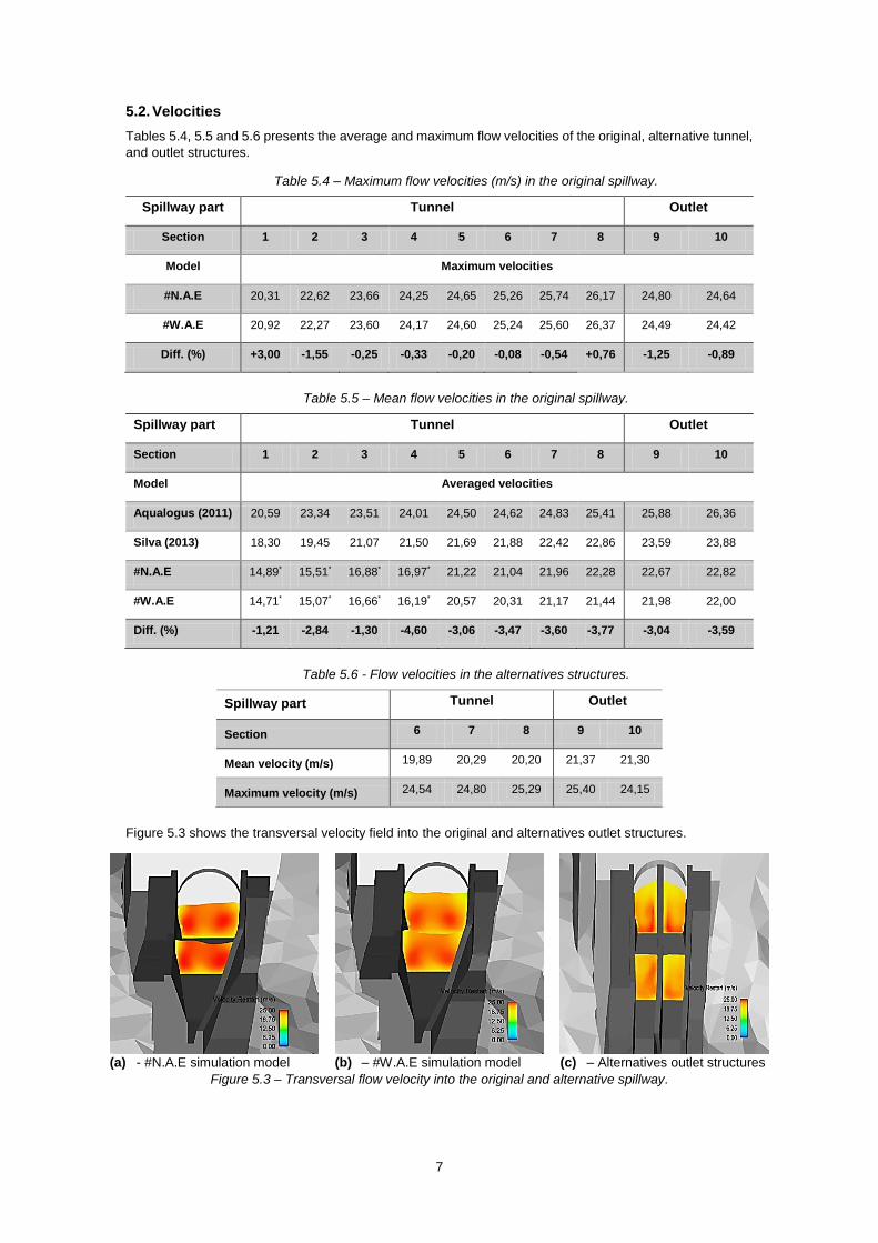
Figure 5.3 shows the transversal velocity field into the original and alternatives outlet structures.
(a) - #N.A.E simulation model (b) – #W.A.E simulation model (c) – Alternatives outlet structures
Figure 5.3 – Transversal flow velocity into the original and alternative spillway.
8
The obtained results show a global velocity reduction at the outlet structures. This probably occurs due to
the bulking effect simulation. These results contradict the theoretical expected tendency, which suggested
higher velocity values due to a lower flow resistance that occurs by water-air shear reduction.
Average flow velocities results, signalled by (*), are out of the expected range. The FlowSight® post-
processing software presents a higher average errors values in mesh blocks that were not aligned to the
preferential direction flow. This occurs in the first references sections, due the bended configuration of the
tunnel structure into this mesh block region.
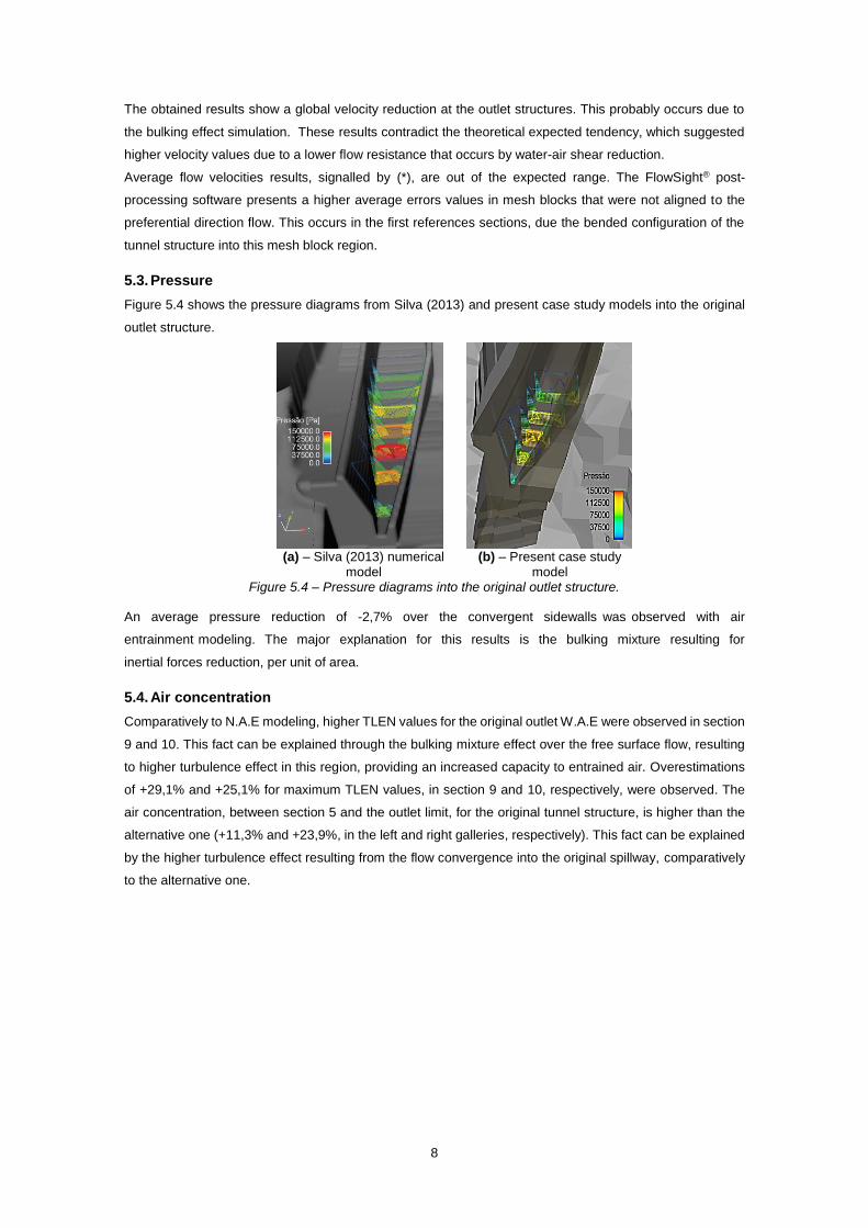
5.3. Pressure
Figure 5.4 shows the pressure diagrams from Silva (2013) and present case study models into the original
outlet structure.
(a) – Silva (2013) numerical
model (b) – Present case study
model Figure 5.4 – Pressure diagrams into the original outlet structure.
An average pressure reduction of -2,7% over the convergent sidewalls was observed with air
entrainment modeling. The major explanation for this results is the bulking mixture resulting for
inertial forces reduction, per unit of area.
5.4. Air concentration
Comparatively to N.A.E modeling, higher TLEN values for the original outlet W.A.E were observed in section
9 and 10. This fact can be explained through the bulking mixture effect over the free surface flow, resulting
to higher turbulence effect in this region, providing an increased capacity to entrained air. Overestimations
of +29,1% and +25,1% for maximum TLEN values, in section 9 and 10, respectively, were observed. The
air concentration, between section 5 and the outlet limit, for the original tunnel structure, is higher than the
alternative one (+11,3% and +23,9%, in the left and right galleries, respectively). This fact can be explained
by the higher turbulence effect resulting from the flow convergence into the original spillway, comparatively
to the alternative one.
9
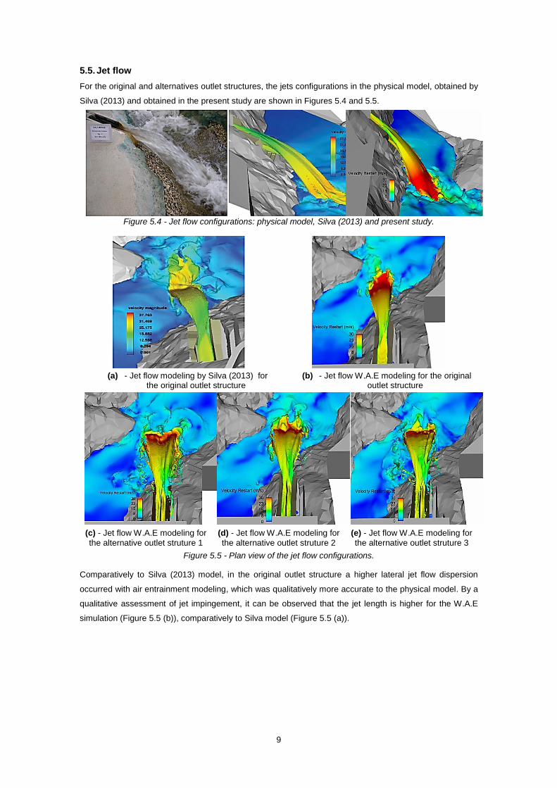
5.5. Jet flow
For the original and alternatives outlet structures, the jets configurations in the physical model, obtained by
Silva (2013) and obtained in the present study are shown in Figures 5.4 and 5.5.
Figure 5.4 - Jet flow configurations: physical model, Silva (2013) and present study.
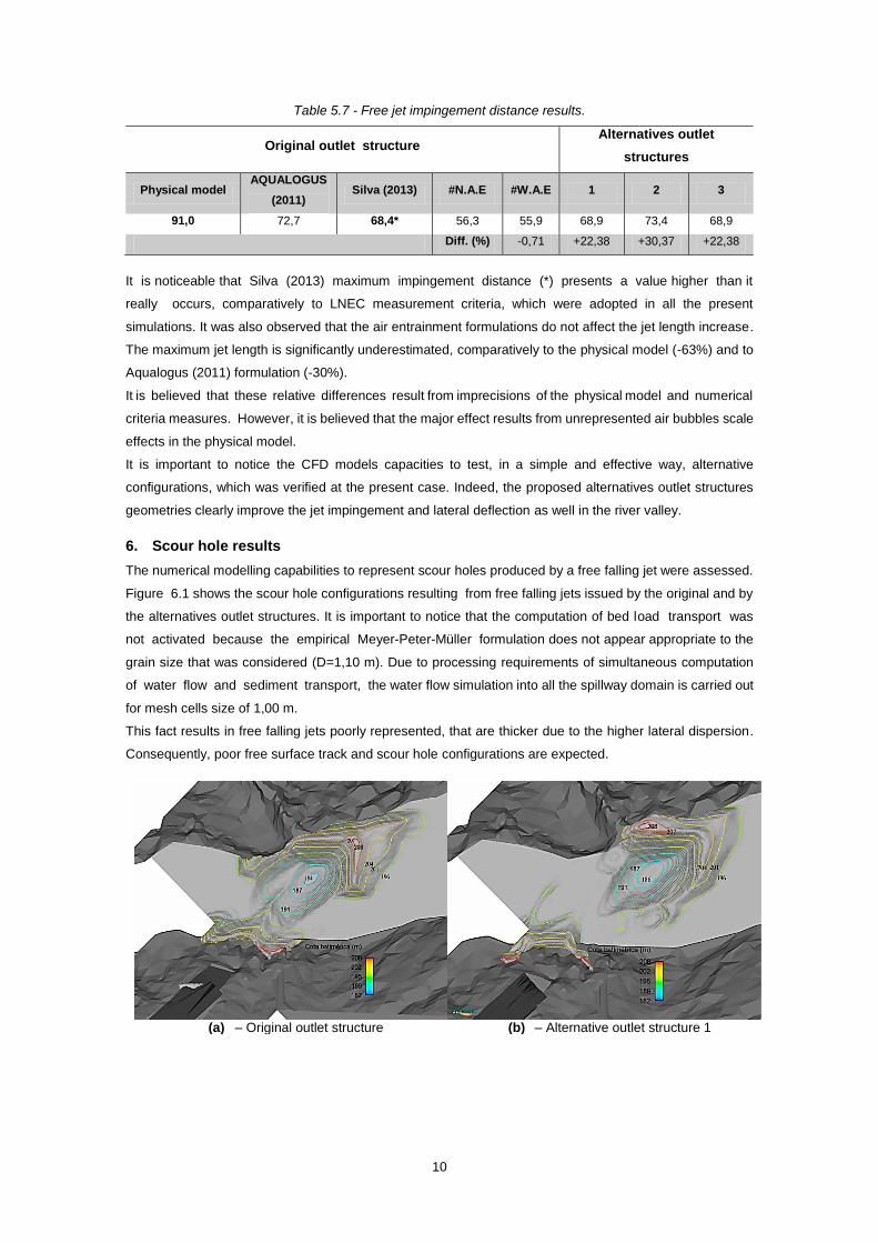
(a) - Jet flow modeling by Silva (2013) for the original outlet structure
(b) - Jet flow W.A.E modeling for the original outlet structure
(c) - Jet flow W.A.E modeling for
the alternative outlet struture 1
(d) - Jet flow W.A.E modeling for
the alternative outlet struture 2
(e) - Jet flow W.A.E modeling for
the alternative outlet struture 3
Figure 5.5 - Plan view of the jet flow configurations.
Comparatively to Silva (2013) model, in the original outlet structure a higher lateral jet flow dispersion
occurred with air entrainment modeling, which was qualitatively more accurate to the physical model. By a
qualitative assessment of jet impingement, it can be observed that the jet length is higher for the W.A.E
simulation (Figure 5.5 (b)), comparatively to Silva model (Figure 5.5 (a)).
10
Table 5.7 - Free jet impingement distance results.
Original outlet structure Alternatives outlet
structures
Physical model AQUALOGUS
(2011) Silva (2013) #N.A.E #W.A.E 1 2 3
91,0 72,7 68,4* 56,3 55,9 68,9 73,4 68,9
Diff. (%) -0,71 +22,38 +30,37 +22,38
It is noticeable that Silva (2013) maximum impingement distance (*) presents a value higher than it
really occurs, comparatively to LNEC measurement criteria, which were adopted in all the present
simulations. It was also observed that the air entrainment formulations do not affect the jet length increase.
The maximum jet length is significantly underestimated, comparatively to the physical model (-63%) and to
Aqualogus (2011) formulation (-30%).
It is believed that these relative differences result from imprecisions of the physical model and numerical
criteria measures. However, it is believed that the major effect results from unrepresented air bubbles scale
effects in the physical model.
It is important to notice the CFD models capacities to test, in a simple and effective way, alternative
configurations, which was verified at the present case. Indeed, the proposed alternatives outlet structures
geometries clearly improve the jet impingement and lateral deflection as well in the river valley.
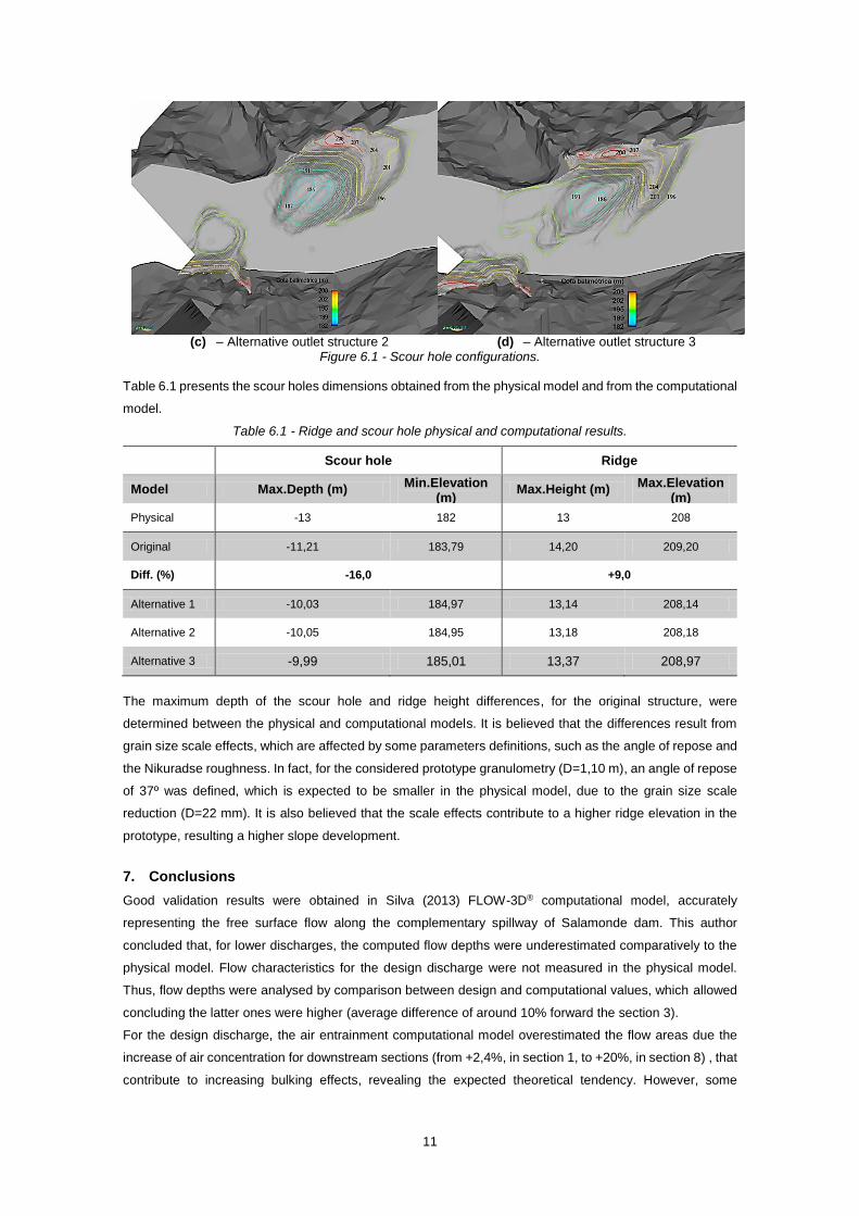
6. Scour hole results
The numerical modelling capabilities to represent scour holes produced by a free falling jet were assessed.
Figure 6.1 shows the scour hole configurations resulting from free falling jets issued by the original and by
the alternatives outlet structures. It is important to notice that the computation of bed load transport was
not activated because the empirical Meyer-Peter-Müller formulation does not appear appropriate to the
grain size that was considered (D=1,10 m). Due to processing requirements of simultaneous computation
of water flow and sediment transport, the water flow simulation into all the spillway domain is carried out
for mesh cells size of 1,00 m.
This fact results in free falling jets poorly represented, that are thicker due to the higher lateral dispersion.
Consequently, poor free surface track and scour hole configurations are expected.
(a) – Original outlet structure (b) – Alternative outlet structure 1
11
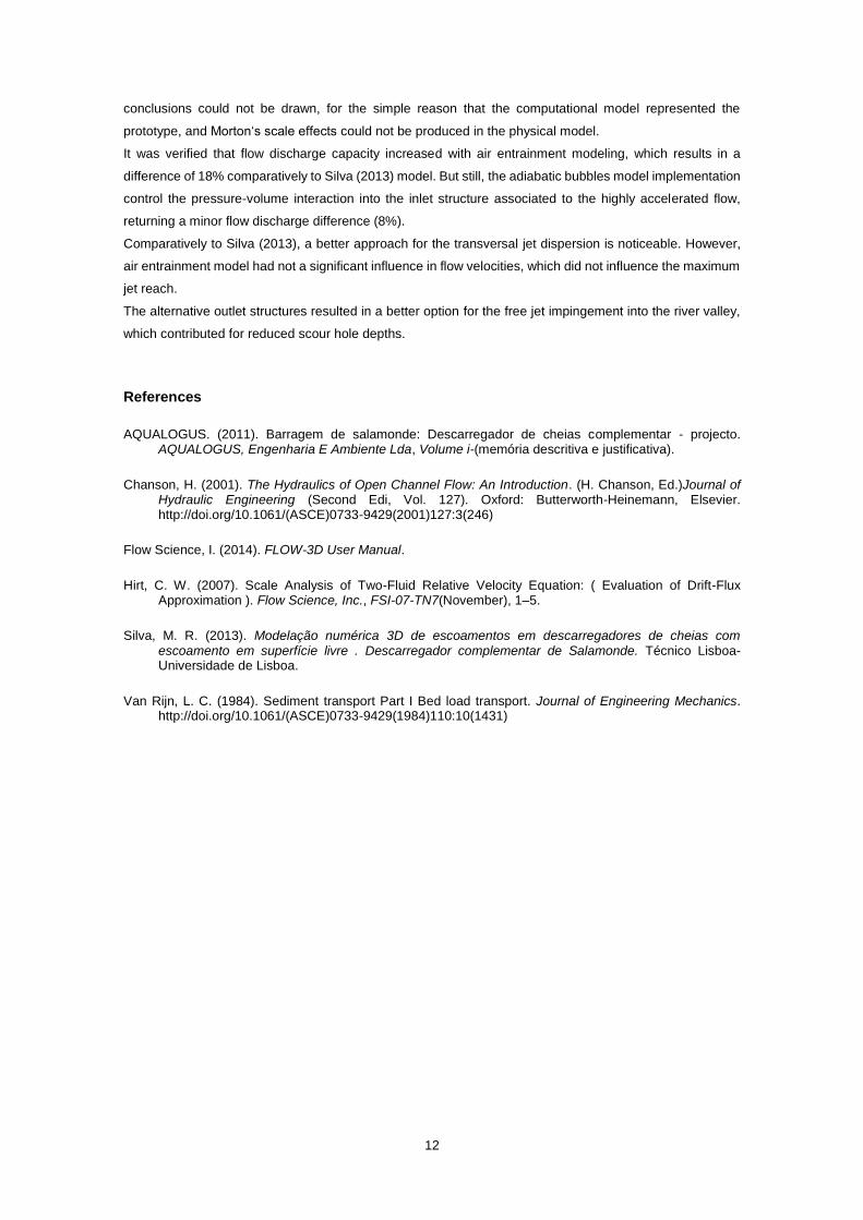
(c) – Alternative outlet structure 2 (d) – Alternative outlet structure 3
Figure 6.1 - Scour hole configurations.
Table 6.1 presents the scour holes dimensions obtained from the physical model and from the computational
model.
Table 6.1 - Ridge and scour hole physical and computational results.
Scour hole Ridge
Model Max.Depth (m) Min.Elevation
(m) Max.Height (m)
Max.Elevation (m)
Physical -13 182 13 208
Original -11,21 183,79 14,20 209,20
Diff. (%) -16,0 +9,0
Alternative 1 -10,03 184,97 13,14 208,14
Alternative 2 -10,05 184,95 13,18 208,18
Alternative 3 -9,99 185,01 13,37 208,97
The maximum depth of the scour hole and ridge height differences, for the original structure, were
determined between the physical and computational models. It is believed that the differences result from
grain size scale effects, which are affected by some parameters definitions, such as the angle of repose and
the Nikuradse roughness. In fact, for the considered prototype granulometry (D=1,10 m), an angle of repose
of 37º was defined, which is expected to be smaller in the physical model, due to the grain size scale
reduction (D=22 mm). It is also believed that the scale effects contribute to a higher ridge elevation in the
prototype, resulting a higher slope development.
7. Conclusions
Good validation results were obtained in Silva (2013) FLOW-3D® computational model, accurately
representing the free surface flow along the complementary spillway of Salamonde dam. This author
concluded that, for lower discharges, the computed flow depths were underestimated comparatively to the
physical model. Flow characteristics for the design discharge were not measured in the physical model.
Thus, flow depths were analysed by comparison between design and computational values, which allowed
concluding the latter ones were higher (average difference of around 10% forward the section 3).
For the design discharge, the air entrainment computational model overestimated the flow areas due the
increase of air concentration for downstream sections (from +2,4%, in section 1, to +20%, in section 8) , that
contribute to increasing bulking effects, revealing the expected theoretical tendency. However, some
12
conclusions could not be drawn, for the simple reason that the computational model represented the
prototype, and Morton‘s scale effects could not be produced in the physical model.
It was verified that flow discharge capacity increased with air entrainment modeling, which results in a
difference of 18% comparatively to Silva (2013) model. But still, the adiabatic bubbles model implementation
control the pressure-volume interaction into the inlet structure associated to the highly accelerated flow,
returning a minor flow discharge difference (8%).
Comparatively to Silva (2013), a better approach for the transversal jet dispersion is noticeable. However,
air entrainment model had not a significant influence in flow velocities, which did not influence the maximum
jet reach.
The alternative outlet structures resulted in a better option for the free jet impingement into the river valley,
which contributed for reduced scour hole depths.
References
AQUALOGUS. (2011). Barragem de salamonde: Descarregador de cheias complementar - projecto. AQUALOGUS, Engenharia E Ambiente Lda, Volume i-(memória descritiva e justificativa).
Chanson, H. (2001). The Hydraulics of Open Channel Flow: An Introduction. (H. Chanson, Ed.)Journal of Hydraulic Engineering (Second Edi, Vol. 127). Oxford: Butterworth-Heinemann, Elsevier. http://doi.org/10.1061/(ASCE)0733-9429(2001)127:3(246)
Flow Science, I. (2014). FLOW-3D User Manual.
Hirt, C. W. (2007). Scale Analysis of Two-Fluid Relative Velocity Equation: ( Evaluation of Drift-Flux Approximation ). Flow Science, Inc., FSI-07-TN7(November), 1–5.
Silva, M. R. (2013). Modelação numérica 3D de escoamentos em descarregadores de cheias com escoamento em superfície livre . Descarregador complementar de Salamonde. Técnico Lisboa- Universidade de Lisboa.
Van Rijn, L. C. (1984). Sediment transport Part I Bed load transport. Journal of Engineering Mechanics. http://doi.org/10.1061/(ASCE)0733-9429(1984)110:10(1431)