3d perception and planning for self-driving and ... · 3d perception and planning for self-driving...
TRANSCRIPT

3D Perception and Planning for Self-Driving and CooperativeAutomobiles
Christoph Stiller and Julius Ziegler
Abstract—This presentation focusses on key technologies forautomobiles that perceive a priori unknown environment andautomatically navigate through everyday traffic. Methods for3D Machine perception based on lidar and video sensors areoutlined. Beyond classical metrology, the recognition and basicunderstanding of situations must be accomplished for automatedtrajectory planning in urban traffic. We discuss how to representand acquire metric, symbolic and conceptual knowledge fromvideo and lidar data of a vehicle. A hardware and software ar-chitecture tailored to this knowledge structure for an autonomousvehicle is proposed. Emphasis is laid on methods for situationrecognition employing geometrical and topological reasoning andMarkov Logic Networks. A quality measure for trajectories isimposed that considers safety, efficiency, and comfort. We adopta flat input parameterization to plan trajectories that optimizethe imposed quality measure. Results from the autonomousvehicle AnnieWAY that recently won the Grand CooperativeDriving Challenge are shown in real world urban and platooningscenarios.
I. INTRODUCTION
Autonomous Vehicles that perceive their environment, com-municate with each other, understand the current traffic situa-tion and may by themselves or cooperatively with others planand conduct appropriate driving trajectories are an intense fieldof international research. This contribution outlines the con-cept and architecture of the ’Cognitive Automobile AnnieWAY’that has successfully participated in international competitionssuch as the 2005 Grand and the 2007 Urban Challenge, andrecently won the 2011 Grand Cooperative Driving Challenge[1], [2], [3], [4]. The vehicle constitutes an experimental basisfor automated machine behaviour [5], [6]. Within a few years,large improvements in traffic safety is expected from suchtechnologies [7].
A major goal of the scientific research is to advance knowl-edge acquisition and representation as a basis for automateddecisions. As illustrated in Figure 1, driving - whether bya human or by a cognitive machine - involves knowledgerepresentation in various forms. Metric knowledge, such asthe lane geometry and the position or velocity of other trafficparticipants is required to keep the vehicle on the lane at asafe distance to others. Symbolic knowledge, e.g. classifyinglanes as either ’vehicle lane forward’, ’vehicle lane rearward’,’bicyle lane’, ’walkway’, etc. is needed to conform with basicrules. Finally, conceptual knowlegde, e.g. specifying a rela-tionship between other traffic participants allows to anticipatethe expected evolution of the scene to drive foresightedly.
C. Stiller and J. Ziegler are with Institut fur Mess- und Regelungstech-nik, KIT - Karlsruher Institut fur Technologie, 76131 Karlsruhe, Germanystiller, [email protected]
25 m 30 km/h
S2
P2 P3
S1
P1
S3
P1 follows
P3
vehicle lane forward
bicycle lane
Fig. 1: Metric (yellow), symbolic (orange), and conceptual(red) knowledge for cognitive automobiles
II. ANNIEWAY SYSTEM OVERVIEW
A. AnnieWAY Hardware Architecture
Embodiment is widely considered a crucial element incognitive systems research. To assess and validate theoreticalfindings we have adopted the unified hardware and softwareframework of the Karlsruhe-Munich collaborate research cen-ter ’cognitive automobiles’ [8], [9]. Based on the architecturedepicted in Figure 2, meanwhile some ten experimental cog-nitive automobiles were set up [10], [6], [11]. To ensure real-
GPS-Antennas
3D-LIDAR
2D-LIDAR
Stereo Vision
Control Computer IMU
Power Supply
Main Computer Radar
E-Throttle E-Brakes E-Steering
V2V Communication
Fig. 2: Hardware setup for the cooperative cognitive automo-bile AnnieWAY.
time capabilities, vehicle control is performed on a dedicateddSpace AutoBox which directly communicates with the actu-ators over the vehicle CAN. All other perception and planningmodules as well as sensor data acquisition are performedby a single multicore multiprocessor computer system whichdelivers sufficient computing power to host all processesproviding low latencies and high bandwidth for inter-processcommunication.
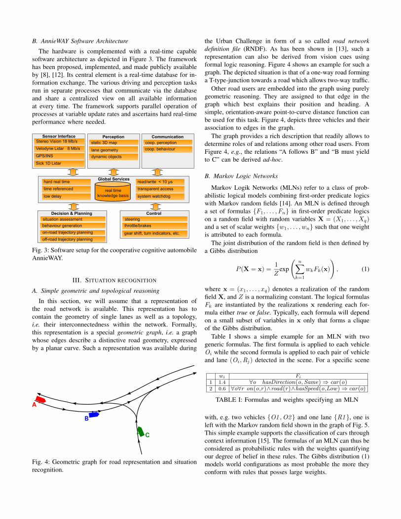
B. AnnieWAY Software ArchitectureThe hardware is complemented with a real-time capable
software architecture as depicted in Figure 3. The frameworkhas been proposed, implemented, and made publicly availableby [8], [12]. Its central element is a real-time database for in-formation exchange. The various driving and perception tasksrun in separate processes that communicate via the databaseand share a centralized view on all available informationat every time. The framework supports parallel operation ofprocesses at variable update rates and ascertains hard real-timeperformance where needed.
Velodyne Lidar 8 Mb/s
Sensor Interface
Global Services ServicDienste
real time knowledge basis
GPS/INS
Sick 1D Lidar
Perception static 3D map
dynamic objects
transparent access
system watchdog
read/write < 10 !s
time referenced
low delay
hard real time
behaviour generation
Decision & Planning situation assessment
throttle/brakes
Control steering
gear shift, turn indicators, etc.
Stereo Vision 18 Mb/s
coop. behaviour
Communication coop. perception
lane geometry
on-road trajectory planning
off-road trajectory planning
Fig. 3: Software setup for the cooperative cognitive automobileAnnieWAY.
III. SITUATION RECOGNITION
A. Simple geometric and topological reasoningIn this section, we will assume that a representation of
the road network is available. This representation has tocontain the geometry of single lanes as well as a topology,i.e. their interconnectedness within the network. Formally,this representation is a special geometric graph, i.e. a graphwhose edges describe a distinctive road geometry, expressedby a planar curve. Such a representation was available during
Fig. 4: Geometric graph for road representation and situationrecognition.
the Urban Challenge in form of a so called road networkdefinition file (RNDF). As has been shown in [13], such arepresentation can also be derived from vision cues usingformal logic reasoning. Figure 4 shows an example for such agraph. The depicted situation is that of a one-way road forminga T-type-junction towards a road which allows two-way traffic.
Other road users are embedded into the graph using purelygeometric reasoning. They are assigned to that edge in thegraph which best explains their position and heading. Asimple, orientation-aware point-to-curve distance function canbe used for this task. Figure 4, depicts three vehicles and theirassociation to edges in the graph.
The graph provides a rich description that readily allows todetermine roles of and relations among other road users. FromFigure 4, e.g., the relations “A follows B” and “B must yieldto C” can be derived ad-hoc.
B. Markov Logic Networks
Markov Logik Networks (MLNs) refer to a class of prob-abilistic logical models combining first-order predicate logicswith Markov random fields [14]. An MLN is defined througha set of formulas {F1, . . . , Fn} in first-order predicate logicson a random field with random variables X = (X1, . . . , Xq)and a set of scalar weights {w1, . . . , wn} such that one weightis attributed to each formula.
The joint distribution of the random field is then defined bya Gibbs distribution
P (X = x) =1
Zexp
�n�
k=1
wkFk(x)
�, (1)
where x = (x1, . . . , xq) denotes a realization of the randomfield X, and Z is a normalizing constant. The logical formulasFk are instantiated by the realizations x rendering each for-mula either true or false. Typically, each formula will dependon a small subset of variables in x only that forms a cliqueof the Gibbs distribution.
Table I shows a simple example for an MLN with twogeneric formulas. The first formula is applied to each vehicleOi while the second formula is applied to each pair of vehicleand lane (Oi ,Rj ) detected in the scene. For a specific scene
wi Fi
1 1.4 ∀o hasDirection(o,Same) ⇒ car(o)2 0.6 ∀o∀r on(o,r)∧road(r)∧hasSpeed(o,Low) ⇒ car(o)
TABLE I: Formulas and weights specifying an MLN
with, e.g. two vehicles {O1 ,O2} and one lane {R1}, one isleft with the Markov random field shown in the graph of Fig. 5.This simple example supports the classification of cars throughcontext information [15]. The formulas of an MLN can thus beconsidered as probabilistic rules with the weights quantifyingour degree of belief in these rules. The Gibbs distribution (1)models world configurations as most probable the more theyconform with rules that posses large weights.
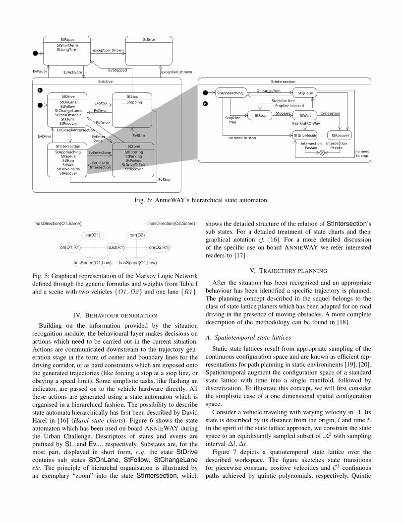
Fig. 6: AnnieWAY’s hierarchical state automaton.
hasDirection(O1,Same) hasDirection(O2,Same)
on(O1,R1) on(O2,R1)
car(O1) car(O2)
road(R1)
hasSpeed(O1,Low) hasSpeed(O1,Low)
Fig. 5: Graphical representation of the Markov Logic Networkdefined through the generic formulas and weights from Table Iand a scene with two vehicles {O1 ,O2} and one lane {R1}.
IV. BEHAVIOUR GENERATION
Building on the information provided by the situationrecognition module, the behavioural layer makes decisions onactions which need to be carried out in the current situation.Actions are communicated downstream to the trajectory gen-eration stage in the form of center and boundary lines for thedriving corridor, or as hard constraints which are imposed ontothe generated trajectories (like forcing a stop at a stop line, orobeying a speed limit). Some simplistic tasks, like flashing anindicator, are passed on to the vehicle hardware directly. Allthese actions are generated using a state automaton which isorganised in a hierarchical fashion. The possibility to describestate automata hierarchically has first been described by DavidHarel in [16] (Harel state charts). Figure 6 shows the stateautomaton which has been used on board ANNIEWAY duringthe Urban Challenge. Descriptors of states and events areprefixed by St...and Ev..., respectively. Substates are, for themost part, displayed in short form, e.g. the state StDrive
contains sub states StOnLane, StFollow, StChangeLane
etc. The principle of hierarchal organisation is illustrated byan exemplary “zoom” into the state StIntersection, which
shows the detailed structure of the relation of StIntersection’ssub states. For a detailed treatment of state charts and theirgraphical notation cf. [16]. For a more detailed discussionof the specific use on board ANNIEWAY we refer interestedreaders to [17].
V. TRAJECTORY PLANNING
After the situation has been recognized and an appropriatebehaviour has been identified a specific trajectory is planned.The planning concept described in the sequel belongs to theclass of state lattice planers which has been adapted for on roaddriving in the presence of moving obstacles. A more completedescription of the methodology can be found in [18].
A. Spatiotemporal state lattices
Static state lattices result from appropriate sampling of thecontinuous configuration space and are known as efficient rep-resentations for path planning in static environments [19], [20].Spatiotemporal augment the configuration space of a standardstate lattice with time into a single manifold, followed bydiscretization. To illustrate this concept, we will first considerthe simplistic case of a one dimensional spatial configurationspace.
Consider a vehicle traveling with varying velocity in . Itsstate is described by its distance from the origin, l and time t.In the spirit of the state lattice approach, we constrain the statespace to an equidistantly sampled subset of 2 with samplinginterval ∆l,∆t.
Figure 7 depicts a spatiotemporal state lattice over thedescribed workspace. The figure sketches state transitionsfor piecewise constant, positive velocities and C2 continuouspaths achieved by quintic polynomials, respectively. Quintic

Fig. 7: A spatiotemporal state lattice over a one dimensionalworkspace. The lower left shaded area depicts a control setfor paths in C0 while the upper right one depicts one designedfor higher order continuity, consisting of quintic polynomials.
polynomials are attractive for planning dynamic driving ma-noeuvres, because they minimize squared jerk [21] and allowfor fast computation of their coefficients for given boundaryconditions. Closed form expressions exist to describe theintegral of squared jerk and for maximum speed, accelerationand speed along the trajectory [22]. Quintic splines have beenused for automotive motion planning before [23], albeit onlyto describe kinematic paths without time parametrization.
B. Motion planning using spatiotemporal state lattices
In order to account for moving obstacles their future posi-tions are predicted. Obstacles can then readily be transferredto the space-time manifold, as shown in Figure 8. The shadedarea is occupied by a small object that moves with velocity12∆l∆t . A trajectory is found within the spatiotemporal lattice
that does not collide with the obstacle.To deal with obstacles efficiently, we create a mapping
between a discrete space-time obstacle map and the set ofall edges in the graph. This can be done in the offline graphgeneration phase. Then, edges blocked by obstacles can beinvalidated quickly by a single run over the obstacle map. Thismethod scales well with the number of obstacles maintainingan almost constant overall processing time.
Edge costs consider the integral of the squared jerk of theirgeometric representations, as opposed to simply consideringarc length. This improves safety, controllability and drivingcomfort.
Graph-based motion planning algorithms usually employshortest path algorithms that maintain vertices visited in apartially ordered data structure. Algorithms belonging to thisclass include A* search, as well as Stentz’ D* [24] and focusedD* [25]. Spatiotemporal lattices belong to the class of directedacyclic graphs (DAG). Hence, sorting vertices by time yieldsa topological ordering in advance, and vertices can be justprocessed in this order. The resulting algorithm is linear inthe number of vertices n, as opposed to Dijkstra’s generalscheme which is in O(n log n).
Fig. 8: Planning with a moving obstacle in the space-timemanifold. The shaded area is covered by a moving object. Atrajectory is shown that is composed of elements of the controlset. Shortest paths can be found by relaxing vertices from leftto right.
Fig. 9: Reparametrisation of the Cartesian plane. The dottedline indicates the original run of the road, (X,Y ). The greystructure illustrates the discrete reparametrization in l and r.
C. Lane-adapted reparametrizationThe principle of spatiotemporal state lattices developed in
the preceding sections generalizes naturally to two dimensions.Doing this naıvely, however, produces dimensionality prob-lems due to the required dense sampling of the state space.Note that, in comparison with [20] the dimensionality of thesampling space for the state lattice rises from 3 (2D positionand orientation, in [19], curvature is consider additionally) to7 (2D position, 2D velocity, 2D acceleration and time), due tomoving from a kinematic to a higher order dynamic model andthe incorporation of time. With dimensionality rising, coverageof the configuration space requires an exponentially growingnumber of samples. Hence, an efficient way of sampling theconfiguration space is needed that is adapted to the specialcase of navigating on a road whose run is known a prioi, e.g.from digital map data.
Given a continuous, piecewise twice differentiable, arclength s parametrized representation (X(s), Y (s)) of thecourse of the road, we define the following reparametrization(l, r) of the 2D workspace, where (x, y) denote Cartesiancoordinates, l(t) is the distance travelled along the road, andr(t) is the lateral offset towards the road centre:
x(t) = X(l)− rY �(l) (2)y(t) = Y (l) + rX �(l). (3)
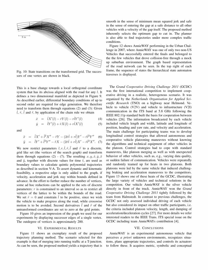
Fig. 10: State transitions on the transformed grid. The succes-sors of one vertex are shown in black.
This is a base change towards a local orthogonal coordinatesystem that has its abcissa aligned with the road for any l. Itdefines a two dimensional manifold as depicted in Figure 9.As described earlier, differential boundary conditions of up tosecond order are required for edge generation. We thereforeneed to transform them through equations (2) and (3): Givenl, r, l and r, by application of the chain rule we obtain
x = lX �(l)− rY (l)− rlY �(l) (4)y = lY �(l) + rX(l) + rlX �(l) (5)
and
x = lX � + l2X ��− rY − (2rl + rl)Y �
− rl2Y �� (6)y = lY � + l2Y ��
− rX − (2rl + rl)X �− rl2X ��. (7)
We now restrict parameters l, r, l, r, l and r to a discrete,grid like set (the vertices of the search graph) and transformthem through equations (2) - (7). The resulting x, y, x, y, xand y, together with discrete values for time t, are used asboundary values to calculate quintic polynomial trajectoriesas described in section V-A. To assert dynamic and kinematicfeasibility, a respective edge is only added to the graph, ifvelocity, acceleration and jerk stay within bounds defined inadvance. In the effort to further reduce the number of vertices,some ad hoc reductions can be applied to the sets of discreteparameters: r is constrained to an interval so as to restrict allvertices of the lattice to be within the bounds of the road.We set r = 0 and constrain l to be positive, since we wishthe vehicle to make progress along the road, while crosswisemotion is to be avoided. Second derivatives l and r of theuntransformed coordinates are set to zero at the grid points.
Figure 10 gives an impression of the graph we used for ourexperiments by displaying successor edges of a single vertex.The outdegree of vertices is approximately 200.
VI. EXPERIMENTAL RESULTS
Figure 11 shows an exemplary result of the proposedtrajectory planning method. The scenario selected for thisexample is that of merging into running traffic at a T-junction.As can be seen, the proposed method yields a trajectory that is
smooth in the sense of minimum mean squared jerk and safein the sense of entering the gap at a safe distance to all othervehicles with a velocity of the gap itself. The proposed methodinherently selects the optimum gap to cut in. The planneris also able to find trajectories under more complex trafficconditions.
Figure 12 shows AnnieWAY performing in the Urban Chal-lenge in 2007, where AnnieWAY was one of only two non-USVehicles that successfully entered the finals and belonged tothe the few vehicles that drove collision-free through a mockup suburban environment. The graph based representationof the road network can be seen. In the top right of eachframe, the sequence of states the hierarchical state automatontraverses is displayed.
The Grand Cooperative Driving Challenge 2011 (GCDC)was the first international competition to implement coop-erative driving in a realistic, heterogenous scenario. It wasorganized by the Netherlands Organisation for Applied Sci-entific Research (TNO) on a highway near Helmond. Ve-hicle to vehicle (V2V) and vehicle to infrastructure (V2I)communication in the ITS band at 5.8 GHz following theIEEE 802.11p standard built the basis for cooperation betweenvehicles [26]. The information broadcasted by each vehicleincluded vehicle length and width, latitude and longitude ofposition, heading and yaw rate, and velocity and acceleration.The main challenge for participating teams was to developlongitudinal control strategies that allowed autonomous andcooperative vehicle platooning maneuvres without knowingthe algorithms and technical equipment of other vehicles inthe platoon. Control strategies had to cope with standardmaneuvres, like platoon merging as well as with unexpectedbehavior of other vehicles, such as, e.g., varying data quality,or sudden failure of communication. Vehicles were repeatedlyand randomly teamed up for heats in two platoons. Bothplatoons were led by the same vehicle that induced challeng-ing braking and acceleration maneuvres to the competitors.Figure 13 shows one of these heats of the GCDC, illustratingthe large variety of vehicles and technical solutions in thecompetition. Our vehicle AnnieWAY is the silver vehicledirectly in front of the truck. AnnieWAY won the GrandCooperative Driving Challenge 2011 tightly followed by theteam from Halmstedt. In contrast to previous challenges, theGCDC not only assessed individual driving of each vehiclebut also considered its impact on other traffic participants, i.e.the criteria included platoon velocity, length, and damping ofacceleration/deceleration cycles [27]. For more details we referinterested readers to the IEEE Trans. ITS special issue on theGCDC including team AnnieWAYs contribution [4].
VII. CONCLUSIONS
AnnieWAY is an experimental autonomous vehicle thatperceives a priori unknown environments, recognizes situa-tions, plans appropriate trajectories, and controls its actuatorsto follow these. It acquires metric, symbolic and conceptual
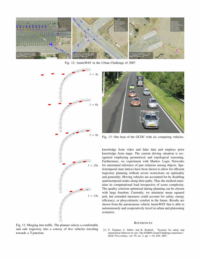
Fig. 12: AnnieWAY in the Urban Challenge of 2007
t = 4s
t = 6s
t = 8s
t = 10s
t = 12s
Fig. 11: Merging into traffic. The planner selects a comfortableand safe trajectory into a convoy of five vehicles travelingtowards a T-junction.
Fig. 13: One heat of the GCDC with six competing vehicles.
knowledge from video and lidar data and employs priorknowledge from maps. The current driving situation is rec-ognized employing geometrical and topological reasoning.Furthermore, we experiment with Markov Logic Networksfor automated inference of pair relations among objects. Spa-tiotemporal state lattices have been shown to allow for efficienttrajectory planning without severe restrictions on optimalityand generality. Moving vehicles are accounted for by disablingspatiotemporal nodes along their paths. Thus the method main-tains its computational load irrespective of scene complexity.The quality criterion optimized during planning can be chosenwith large freedom. Currently, we minimize mean squaredjerk, but extended measures could account for safety, energyefficiency, or phsycokinetic comfort in the future. Results areshown from the autonomous vehicle AnnieWAY that is able toautonomously and cooperatively travel in urban and platooningscenarios.
REFERENCES
[1] U. Ozguner, C. Stiller, and K. Redmill, “Systems for safety andautonomous behavior in cars: The DARPA Grand Challenge experience,”IEEE Proceedings, vol. 95, no. 2, pp. 1–16, Feb. 2007.

[2] Soren Kammel, Julius Ziegler, Benjamin Pitzer, Moritz Werling, TobiasGindele, Daniel Jagzent, Joachim Schroder, Michael Thuy, MatthiasGoebl, Felix von Hundelshausen, Oliver Pink, Christian Frese, andChristoph Stiller, “Team AnnieWAY’s autonomous system for the 2007DARPA Urban Challenge,” Journal of Field Robotics, vol. 25, no. 9,pp. 615 – 639, Sept. 2008.
[3] F. v. Hundelshausen, M. Himmelsbach, F. Hecker, A. Mueller, and H.-J.Wuensche, “Driving with tentacles: Integral structures for sensing andmotion,” Journal of Field Robotics, vol. 25, no. 9, pp. 640 – 673, Sept.2008.
[4] Andreas Geiger, Martin Lauer, Frank Moosmann, Benjamin Ranft, Hol-ger Rapp, Christoph Stiller, and Julius Ziegler, “Team annieway’s entryto the grand cooperative driving challenge 2011,” IEEE Transactionson Intelligent Transportation Systems (in print), 2012.
[5] C. Stiller, G. Farber, and S. Kammel, “Cooperative cognitive automo-biles,” in Proc. IEEE Intelligent Vehicles Symposium, Istanbul, Turkey,June 2007, pp. 215–220.
[6] M. Thuy, M. Althoff, M. Buss, K. Diepold, J. Eberspacher, G. Farber,M. Goebl, B. Heißing, S. Kraus, R. Nagel, Y. Naous, F. Ober-meier, F. Puente Leon, F. Rattei, C. Wang, M. Schweitzer, and H.J.Wunsche, “Kognitive Automobile - Neue Konzepte und Ideen desSonderforschungsbereiches/TR-28,” in 3. Tagung Aktive Sicherheitdurch Fahrerassistenz, Garching bei Munchen, 2008.
[7] European Union, “E-Safety,”http://www.ec.europa.eu/information society/activities/esafety, Novem-ber 2010.
[8] Matthias Goebl and Georg Farber, “A real-time-capable hard- andsoftware architecture for joint image and knowledge processing incognitive automobiles,” in Proc. IEEE Intelligent Vehicles Symposium,Istanbul, Turkey, June 2007, pp. 734–739.
[9] Moritz Werling, Matthias Goebl, Oliver Pink, and Christoph Stiller, “Ahardware and software framework for cognitive automobiles,” in Pro-ceedings of the IEEE Intelligent Vehicles Symposium 2008, Eindhoven,Niederlande, 2008, pp. 1080 – 1085.
[10] M. Goebl, M. Althoff, M. Buss, G. Farber, F. Hecker, B. Heißing,S. Kraus, R. Nagel, F. Puente Leon, F. Rattei, M. Russ, M. Schweitzer,M. Thuy, C. Wang, and H.J. Wuensche, “Design and Capabilities ofthe Munich Cognitive Automobile,” in Proc. IEEE Intelligent VehiclesSymposium, Eindhoven, the Netherlands, June 2008, pp. 1101–1107.
[11] J. Schroder, T. Gindele, D. Jagszent, and R. Dillmann, “Path planningfor cognitive vehicles,” in Proceedings of the IEEE Intelligent VehiclesSymposium, Eindhoven, Holland, 2008, pp. 1119–1124.
[12] Matthias Goebl, Eine realzeitfahige Architektur zur Integration kog-nitiver Funktionen, Dissertation, Technische Universitat Munchen,Munchen, 2009.
[13] Britta Hummel, Werner Thiemann, and Irina Lulcheva, “Descriptionlogic for vision-based intersection understanding,” in Proc. CognitiveSystems with Interactive Sensors (COGIS), 2007.
[14] Matthew Richardson and Pedro Domingos, “Markov logic networks,”Machine Learning, vol. 62, no. 1-2, pp. 107–136, 2006.
[15] C. Stiller, S.Kammel, I. Lulcheva, and J.Ziegler, “Probabilistic methodsfor environment perception of cognitive automobiles,” at - Automation,vol. 11, pp. 568–574, 2008.
[16] David Harel, “Statecharts: A visual formalism for complex systems,”Science of Computer Programming, vol. 8, no. 3, pp. 231–274, June1987.
[17] Tobias Gindele, Daniel Jagzent, Ben Pitzer, and Rudiger Dillmann,“Design of the planner of team annieway’s autonomous vehicle used inthe darpa urban challenge 2007,” in Proceedings of the IEEE IntelligentVehicles Symposium, Eindhoven, Die Niederlande, 2008.
[18] Julius Ziegler and Christoph Stiller, “Spatiotemporal state lattices forfast trajectory planning in dynamic on-road driving scenarios,” inInternational Conference on Intelligent Robots and Systems, 2009.
[19] M. Pitvoraiko and A. Kelly, “Efficient constrained path planning viasearch in state lattices,” in International Symposium on ArtificialIntelligence, Robotics, and Automation in Space, 2005.
[20] Maxim Likhachev and Dave Ferguson, “Planning long dynamically-feasible maneuvers for autonomous vehicles,” in Proceedings ofRobotics: Science and Systems IV, 2008.
[21] A. Takahashi, T. Hongo, Y. Ninomiya, and G. Sugimoto, “Local pathplanning and motion control for AGV in positioning,” in InternationalWorkshop on Intelligent Robots and Systems, 1989.
[22] R.L Andersson, “Aggressive trajectory generator for a robot ping-pongplayer,” Control Systems Magazine, vol. 9, pp. 15–21, 1989.
[23] A. Piazzi, C.G. Lo Bianco, M. Bertozzi, A. Fascioli, and A. Broggi,“Quintic G2-splines for the iterative steering of vision-based au-tonomous vehicles,” Transactions on Intelligent Transportation Systems,vol. 3, pp. 27–36, 2002.
[24] A. Stentz, “Optimal and efficient path planning for partially-knownenvironments,” in International Conference on Robotics and Automation,1994.
[25] A. Stentz, “The focussed D* algorithm for real-time replanning,” inInternational Joint Conference on Artificial Intelligence, 1995.
[26] D. Jiang and L. Delgrossi, “IEEE 802.11p: Towards an internationalstandard for wireless access in vehicular environments,” in IEEEVehicular Technology Conference Spring 2008, 2008, pp. 2036–2040.
[27] Martin Lauer and Anton Gerrits, “Next steps for the grand cooperativedriving challenge,” IEEE Intelligent Transportation Systems Magazine,vol. 1, no. 4, pp. 24–32, 2010.