3d piecewise planar object model for robotics … in 2d using homographies and ... representation...
TRANSCRIPT

3D Piecewise Planar Object Model for Robotics Manipulation
Johann Prankl, Michael Zillich, and Markus Vincze
Abstract— Man-made environments are abundant with pla-nar surfaces which have attractive properties for roboticsmanipulation tasks and are a prerequisite for a variety of visiontasks. This work presents automatic on-line 3D object modelacquisition assuming a robot to manipulate the object. Objectsare represented with piecewise planar surfaces in a spatio-temporal graph. Planes once detected in 2D are tracked andserve as priors in subsequent images. After reconstruction of theplanes the 3D motion is analyzed and initial object hypothesesare created. In case planes start moving independently a splitevent is triggered, the spatio-temporal object graph is tracedback and visible planes as well as occluded planes are assignedto the most probable split object. The novelty of this frameworkis to formalize Multi-body Structure-and-Motion (MSaM), thatis, to segment interest point tracks into different rigid objectsand compute the multiple-view geometry of each object, withMinimal Description Length (MDL) based on model selectionof planes in an incremental manner. Thus, object models arebuilt from planes, which directly can be used for roboticmanipulation.
I. INTRODUCTION
Increasing interest in enabling robot manipulators to oper-ate in everyday environments leads to the problem of how toacquire object models for manipulation. One does not wantto specify all objects and possible obstacles in advance butallow the robot to actively acquire its own models, usingthe robots ability to change view points and to interactwith the scene. Many objects in man-made environmentsconsist of planar surfaces, such as tables, shelves or box-shaped packaging. Also curved surfaces can be approximatedsufficiently accurately for most robotics tasks with piecewiseplanar surfaces, as is common in modelling for computergraphics. Planar surface patches support reasoning aboutobject properties important for manipulation, such as contactpoints and friction cones, in contrast to models based ondistinctive interest points, which typically lead to sparse pointsets and are more suitable for recognition.
Our overall goal is to build a cognitive robotic experi-mentation framework. The rationale behind our system is toenable human tutor driven learning-by-showing as well ascompletely automatic on-line model acquisition by the robot(see Figure 1). Schindler et al. [1] use a model selectionframework for multibody Structure-from-Motion estimationof image sequences. In contrast we use model selection todetect piecewise planar surfaces. We describe plane hypothe-ses using the 2D projective transformation (homography)computed from four interest point pairs in two uncalibratedimages. In the first step our model is simpler than that of
J. Prankl, M. Zillich, and M. Vincze are with the Automa-tion and Control Institute, Vienna University of Technology, Austria{prankl,zillich,vincze}@acin.tuwien.ac.at
camera trajectory
push object
(a) (b)
Fig. 1. Example scenario we used to test our system, where a cameramoves around objects and pushes them. The image shows a stereo setup,from which we use only a single camera.
Schindler, but it enables the robot to interact in more realisticenvironments. After 3D reconstruction of the planes themotion is analyzed and initial object hypotheses are created.In case planes start moving independently a splitting eventis triggered and current visible planes as well as alreadyoccluded planes, stored in a temporal object hypothesesgraph are assigned to the most plausible split object model.For assignment of the planes a Minimal Description Length(MDL) criterion formalizing the colour distribution and thedistance of planes within an object is used. Hence, at eachtimestamp piecewise planar object models of the currentscene are available, which directly can be used for analysisof the shape related to affordances. In case an interest pointdescriptor, such as the popular SIFT proposed by Lowe [2]is computed this model can directly be used for objectrecognition and full pose registration from a single image(see [3] and [4]).
After a review of the related work, we give an overviewof the system in Section II and its core parts, namelythe plane detection (Section II-A), Structure-from-Motion(Section II-B), merging of planes (Section II-C) and splittingof piecewise planar object models (Section II-D). Finally,results of the experiments are shown in Section III.
A. Related work
Although this work focuses on a framework for modellingobjects we first want to mention some literature from the fieldof active vision, which is the motivation for our experimentsshown later on and then tackle related work our system isbased on. The early attempts on Active Vision, that is anactive observer whose purpose is to improve the qualityof the perceptual results, goes back to [5], [6], [7]. In [6]Aloimonos et. al stressed that an active observer can solvebasic vision problems in a much more efficient way. They
introduce a general methodology, in which they believe low-level vision problems should be addressed. Metta et al. [8]developed an active strategy for a robot to acquire visualexperience through simple experimental manipulation. Theexperiments are oriented towards determining what parts ofthe environment are physically coherent, that is, which partswill move together, and which are more or less independent.Our experiments are similar, but in contrast to Meta, whostudies the causal chains of events we focus on learning a 3Dpiecewise planar object model triggered by motion events.
The basic parts of our object model are planes. Detectingplanes in uncalibrated image sequences is well studied.Most approaches use a hypothesize-and-test framework. Apopular method for detecting multiple models is to use therobust estimation method RANSAC [9], to sequentially fitthe model to a data set and then to remove inliers. To generateplane hypotheses Vincent et al. [10] use groups of four pointswhich are likely to be coplanar to compute the homography.To increase the likelihood that the points belong to the sameplane they select points lying on two different lines in animage. In contrast Kanazawa et al. [11] define a probabilityfor feature points to belong to the same plane using theEuclidean distance between the points. Both approaches usea RANSAC scheme, iteratively detect the dominant plane,remove the inliers and precede with the remaining interestpoints. The success of the plane computation depends onthe coplanarity of four matched points. In [12], [13], [14]different strategies are proposed to sequentially reduce theset of points/lines to three pairs. More recent approaches,such as proposed by Toldo et al. [15], Fouhey et al. [16] andChin et al. [17], concentrate on robust estimation of multiplestructures to treat hypotheses equally and do not favourplanes detected first over subsequent planes by greedilyconsuming features. These approaches have to create planehypotheses independently of each other and thus it is notpossible to restrict the search space, which leads to highercomputational complexity. Our method is most similar tothe approach by Prankl et al. [18], who propose incrementalmodel selection based on the MDL principle to overcomethese drawbacks.
The planes, represented by homographies, are the basicentities for 3D reconstruction and for merging/splitting tocreate the final object model. While classical Structure-from-Motion moving through a static scene is essentially solvedin a coherent theory [19], [20] and several robust systemsexist, in recent years, researchers focused on dynamic scenescomposed of rigidly moving objects. The solutions availableso far can be broadly classified into algebraic methods [21],[22], [23], which exploit algebraic constraints satisfied byall scene objects, even though they move relative to eachother, and non-algebraic methods [24], [25], which essen-tially combine rigid SfM with segmentation. Most relatedto our system are the methods proposed by Schindler [1]and by Ozden [26]. They use interleaved segmentation and3D reconstruction of tracked features into independent ob-jects. Instead of directly sampling features and generating3D object hypotheses, we incrementally cluster features to
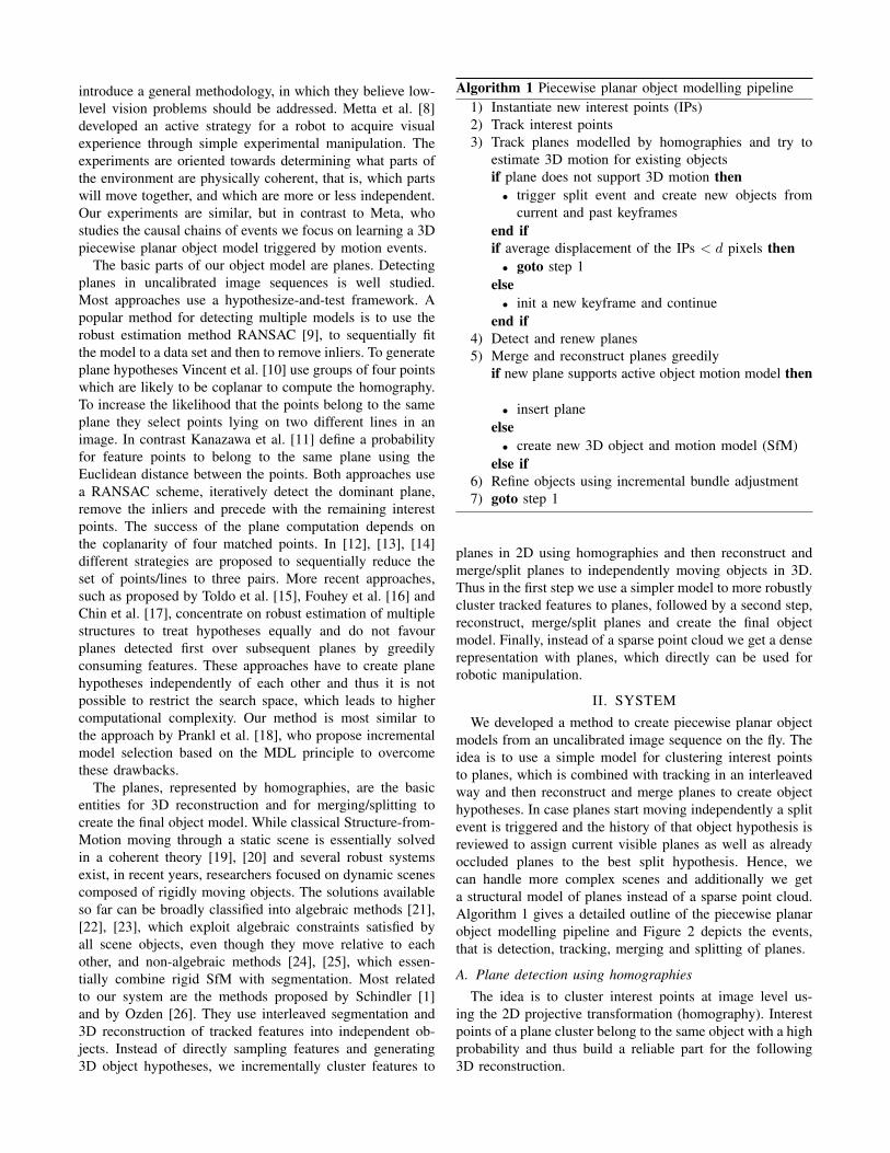
Algorithm 1 Piecewise planar object modelling pipeline1) Instantiate new interest points (IPs)2) Track interest points3) Track planes modelled by homographies and try to
estimate 3D motion for existing objectsif plane does not support 3D motion then• trigger split event and create new objects from
current and past keyframesend ifif average displacement of the IPs < d pixels then• goto step 1
else• init a new keyframe and continue
end if4) Detect and renew planes5) Merge and reconstruct planes greedily
if new plane supports active object motion model then
• insert planeelse• create new 3D object and motion model (SfM)
else if6) Refine objects using incremental bundle adjustment7) goto step 1
planes in 2D using homographies and then reconstruct andmerge/split planes to independently moving objects in 3D.Thus in the first step we use a simpler model to more robustlycluster tracked features to planes, followed by a second step,reconstruct, merge/split planes and create the final objectmodel. Finally, instead of a sparse point cloud we get a denserepresentation with planes, which directly can be used forrobotic manipulation.
II. SYSTEMWe developed a method to create piecewise planar object
models from an uncalibrated image sequence on the fly. Theidea is to use a simple model for clustering interest pointsto planes, which is combined with tracking in an interleavedway and then reconstruct and merge planes to create objecthypotheses. In case planes start moving independently a splitevent is triggered and the history of that object hypothesis isreviewed to assign current visible planes as well as alreadyoccluded planes to the best split hypothesis. Hence, wecan handle more complex scenes and additionally we geta structural model of planes instead of a sparse point cloud.Algorithm 1 gives a detailed outline of the piecewise planarobject modelling pipeline and Figure 2 depicts the events,that is detection, tracking, merging and splitting of planes.
A. Plane detection using homographies
The idea is to cluster interest points at image level us-ing the 2D projective transformation (homography). Interestpoints of a plane cluster belong to the same object with a highprobability and thus build a reliable part for the following3D reconstruction.

detection, reconstruction, merging of planes with common motion and tracking
trace back graph and model separate objects
split event
after pushing
keyframe #X1 keyframe #X2 keyframe #X3
Fig. 2. The upper row shows three keyframes of sequence 1 (897 frames) with detected planes in green which are merged because of common 3D motion.The brightness of the interest points indicates the assignment to different planes. After the gripper (two black dots on the left image border) pushes anobject the keyframe-graph is traced back and two different objects are modelled (lower image row).
Algorithm 2 Plane detection and trackingP ← Ptracked, P ′ ← 0k ← 0, ε←M/N , S ← 0while η = (1− εM )k ≥ η0 doP ′ ← PAdd Z random plane hypotheses to P ′
Select plane hypotheses from P ′ and store in PCount number of explained interest points (inliers) I forPif I > Imax thenImax ← Iε← Imax/N
end ifk ← k + 1
end while
1) Algorithm: Therefore we embedded Minimal Descrip-tion Length (MDL) based model selection in an iterativescheme. Existing planes, tracked from the last images orcreated in the last iteration compete with newly createdhypotheses to ensure that interest points are assigned to thebest current available hypothesis. Additionally hypothesisgeneration is guided to unexplained regions. This methodavoids the bias towards dominant planes typical for iterativemethods, and it limits the search space which leads to a fasterexplanation of the entire image in terms of piecewise planarsurfaces.
Algorithm 2 shows the proposed method for plane de-tection and tracking. In each iteration a small number Z ofnew plane hypotheses P ′ is computed which have to competewith the selected hypotheses P of the last iteration. In the
first iteration P is initialized with tracked planes of the lastimage. The termination criterion is based on the true inlierratio ε and the number of samples M which are necessary tocompute the homographies. As long as we do not know thesevalues we use the best estimate available up to now. For ε thatis the ratio of the number of explained interest points Imax ofthe current best plane hypotheses and the number of matchedinterest points N to explain. Accordingly M is the numberof plane hypotheses currently selected multiplied with theminimal set of interest points m = 4 to compute one planehomography. Furthermore in Algorithm 2 k is the numberof iterations, η stands for the probability that no correct setof hypotheses is found and η0 is the desired failure rate.Due to the incremental scheme it is possible to guide thecomputation of new hypotheses to unexplained regions.
2) Minimal Description Length based model selection:In each iteration selected homographies of the last iterationhave to compete with newly sampled hypotheses. For theselection, the idea is that the same feature cannot belongto more than one plane and that the model cannot be fittedsequentially. Thus an over-complete set of homographies isgenerated and the best subset in terms of a Minimum De-scription Length criterion is chosen. The basic mathematicaltool for this is introduced in [27] and adapted in [28]. Toselect the best model, the savings for each hypothesis h areexpressed as
Sh = Sdata − κ1Smodel − κ2Serror (1)
where in our case Sdata is the number of interest points Nexplained by h and Smodel stands for the cost of codingthe model itself. One model (the homography of a plane) isused and thus Smodel = 1. Serror describes the cost for the

error added, which we express with the log-likelihood overall interest points fk of the plane hypothesis h. Experimentshave shown that the Gaussian error model in conjunctionwith an approximation of the log-likelihood comply with theexpectations. κ1 and κ2 are constants to weight the differentfactors and thus the merit term of a model results in
sii = Sh = −κ1 +N∑
k=1
((1− κ2) + κ2p(fk|h)) , (2)
where p(fk|h) is the likelihood that an interest point belongsto the plane hypothesis h. Details for the derivation ofEquation 2 can be found in [18]. An interest point can only beassigned to one model. Hence, overlapping models competefor interest points which can be represented by interactioncosts
sij = −1
2
∑fk∈hi∩hj
((1− κ2) + κ2 min{p(fk|hi), p(fk|hj)}) .
(3)Finding the optimal possible set of homographies for thecurrent iteration leads to a Quadratic Boolean Problem(QBP)1
maxn
nTSn , S =
s11 · · · s1N...
. . ....
sN1 · · · sNN
(4)
where n= [n1, n2, · · · , nN ] stands for the indicator vectorwith ni = 1 if a plane hypothesis is selected and ni =0 otherwise. This iterative method keeps the number ofhypotheses tractable. Furthermore experiments have shownthat a greedy approximation gives good results and thus thesolution can be found very fast.
B. Structure from Motion (SfM)
The final results of our system are 3D models of objects.Approaching this goal from object reconstruction our systemis strongly related to the dynamic SfM frameworks [1], [26].In [26] Ozden et al. defined the following requirements:
1) Determine the number of independently moving ob-jects at the beginning of a sequence, and wheneverthat number changes
2) Segment the feature tracks into different moving ob-jects in each frame
3) Compute their 3D structure and the camera motion forthe frame
4) Resolve geometric ambiguities5) Robustness to short feature tracks due to occlusion,
motion blur, etc.6) Scale to realistic recording times
They propose interleaved segmentation and 3D reconstruc-tion of the feature tracks into independent objects. Insteadof directly sampling features and generating 3D object hy-potheses we incrementally cluster features to planes in 2D
1QBP assumes pairwise interaction, which in our case can be violated.But this is still a good approximation because interaction always increasescost, yielding a desirable bias against weak hypotheses.
and track them. Thus the first two items as well as the thirdare approached more robustly with a simpler model in 2Dfollowed by reconstruction, clustering and splitting of planesto objects in 3D.
To reconstruct planes which are not assigned to a 3Dmotion model we use a standard SfM pipeline similar toNister et al. [29] and Klein et al. [30]. Therefore the nonlinearrefined homography is directly decomposed to initialize thefirst camera pose (cp. [31]). In the following frames the rela-tive motion from C−1 to C is estimated using RANSAC [9]and a direct least squares solution between the two pointsets (cp. Haralick et al. [32]). A sparse bundle adjustmentimplementation by Lourakis [33] over the last N frames isused to refine camera pose and 3D points of the plane. Oncea plane is reconstructed our algorithm tries to incorporateplanes greedily in case of consistent motion.
C. Merging of planes with consistent motionMerging of planes amounts to checking whether the mo-
tion of a new plane is consistent with the motion of anexisting object. In contrast to Schindler et al. [1] we aim atbuilding individual object models and thus, once an objectis split we do not merge them again if they start movingtogether. Hence, it is possible that several objects with thesame motion are tracked at the same time and a new planemoves consistent with more than one object. If mergingwould be done only because of consistent motion this planewould be assigned to one of the objects just by chance.Therefore a pseudo-likelihood depending on colour and the3D location of interest points is introduced and planes areassigned to the object with a higher probability. Analogousto Equation 2 the formulation
pij = −ε1 +1
N
N∑k=1
((1− ε2) + ε2p(f
proji,k |Hj)
)+ ε3p
∗(ai|Aj) (5)
is used to assign the plane i to the object j with thehigher likelihood pij . In Equation 5 p(fproji,k |Hj) is theprobability that an interest point of a plane i belongs to the3D object Hj . Likewise in Equation 2, this is modelled usinga Gaussian error model. Therefore the camera pose of objectj is used to compute 3D points for plane i and the projectionsare compared to the corresponding tracked image points. εdenote constants to weight the different factors, where ε1 isan offset which must be reached to be considered as movingtogether and ε3 is a weighting factor to reduce the influenceof the appearance model and primarily merge depending onthe motion.
Being aware that merging of planes based on colour and3D interest point adjacency is a critical point, experimentshave shown that for our scenarios, where only a few objectsare modelled simultaneously, this is a good second mergingcriterion next to motion. The likelihood
p∗(ai|Aj) =1
N
N∑k=1
((1− ε4) + ε4p(f
3Di,k |Hj)
)+ log(p(ci|Cj)) (6)

combines these factors in a probabilistic manner. The firstterm describes a probabilistic voting scheme. Therefore aneighbourhood graph of all currently available 3D points isconstructed. This graph is used to compute the mean µ andthe standard deviation σ of the length of edges which connectpoints of the same plane. Then µ and σ are used to computeGaussian votes p(f3Di,k |Hj), where each 3D point of a targetplane votes for the nearest object and thus the object which isclose to the plane accumulates more votes and gets a higherprobability that the plane belongs to that object. The secondterm models the colour distribution of the objects. Thereforewe build the 8 × 8 × 8 colour histogram ci of the targetplane i and the histogram Cj of the object j to which theplane should be assigned. We use normalized rgb colours tobe insensitive to brightness differences of object planes. Theborder of the plane is approximated by the convex hull ofthe interest points. For comparison of colour models we usethe Bhattacharyya coefficient
p(ci|Cj) ∼∑q
√ci(q)Cj(q). (7)
Hence, the probability of a plane i which has to be assignedto an object j consists of a probabilistic vote of each interestpoint to the nearest object and a probability describing thecolour similarity.
D. Separating planes in case of different motions
Motivated by Palmer [34] – who stated that althoughthe vast majority of objects in ordinary environments arestationary the vast majority of the time, ones that move areimportant – we trigger our object modelling if an objectseparates, that is, planes start moving differently. Thereforein Equation 5, which is used to continuously test if planesstart moving separately, ε3 is set to zero and first visibleplanes are separated only because of motion without usingcolour and shape. Then past observations, where the planeshad a common motion are examined. If the camera movesaround an object and planes could not be tracked becauseof (self-)occlusion Equation 6 is used to assign them tothe new object with the higher probability. Therefore werepresent objects in a keyframe2 based graph structure. Eachobservation of an object is assigned to a keyframe and linkedto an observation in the previous as well as in the nextkeyframe. Thus the object itself is stored distributed withinthe graph structure and each observation holds the currentpose to the reference frame and the appearance modelledwith interest points and the colour histogram. Figure 2depicts an event chain where planes are merged because ofcommon motion, start moving separate and thus the objectis split and new object models are built by tracing back thegraph and assigning occluded planes to the object with thehigher probability.
2In our system keyframes are a subset of frames of the whole videosequence, which are automatically selected for plane detection or in case ofan event occurs.
III. EXPERIMENTS
For all experiments we use Shi-Tomasi interest points [35]and a KLT-tracker [36]. In [37] it has been shown that asub-pixel refinement essentially improves pose estimation.Hence, we use the affine refined location of the interestpoints with sub-pixel accuracy and finally compute a non-linear optimized homography using homest [38].
To test our system we use five videos each with about800 frames. Motivated by our cognitive robotic scenariosthe sequences show packaging of arbitrary shapes typicallyfound in a supermarket (see Figure 2). We placed twodifferent objects on a table and manually moved camera andgripper around them in a way that one half of the objectsis already occluded before the gripper pushes one object.The goal of the experiments is that our system detects theplanes, reconstructs, tracks and merges them depending oncommon motion and finally, after pushing one object, createstwo separate piecewise planar object models.
Three numbers are computed to compare the results, thatis the feature based precision
pf,pr =nf,tp
nf,tp + nf,fp(8)
which is the ratio of the number of inliers nf,tp correctlylocated on a ground truth plane and the total number offeatures per detected plane nf,tp+nf,fp. The second numberis the over-segmentation-rate
pov =np,fp
np,tp + np,fp(9)
per plane which indicates how often a plane is replacedduring tracking. np,fp the number of false positives is thenumber of detected planes minus the number of correctlydetected planes np,tp. Furthermore we computed the planebased accuracy
ppl,pr =np,tp
np,tp + np,fp(10)
which describes the ratio of the correctly detected planesnp,tp and the total number of detected planes np,tp + np,fp.
A. Plane detection
To test the plane detection we selected 30 keyframesand manually marked a total number of about 150 planes.With the first video sequence we tested the behaviour of theparameters of our algorithm. Figure 3 shows our performancemeasures for the parameter κ1 = [1...10] and κ2 = [0...1.].It can be seen that our algorithm is quite robust againstvariation of the parameters. Figure 3 (left) shows, thatthe Parameter κ1 mostly influences the over-segmentation-rate while the plane based precision slightly increases. Thefeature based precision pf,pr and the plane based precisionppl,pr are almost constant in Figure 3 (right) and the over-segmentation-rate has a minimum for κ2 = 0.3. The resultsfor all five videos are shown in Table I. It can be seenthat our algorithm did not detect a totally wrong plane(ppl,pr = 1) while in some cases interest points match a planeby chance (pf,pr ≈ 0.97). The over-segmentation-rate pov

0 1 2 3 4 5 6 7 8 9 100
0,10,20,30,40,50,60,70,80,9
1
Precision features Precision planes Over segm.
0 0,1 0,2 0,3 0,4 0,5 0,6 0,7 0,8 0,9 10,000,100,200,300,400,500,600,700,800,901,00
κ1 κ2
Fig. 3. Parameter optimisation
sequence pf,pr ppl,pr pov time per frame [s]1 0.97 1.0 0.40 0.252 0.98 1.0 0.25 0.183 0.93 1.0 0.43 0.154 0.99 1.0 NA 0.195 0.99 1.0 0.60 0.26
TABLE IRESULTS OF OUR FIVE VIDEO SEQUENCES.
would be zero if in the final 3D object model each manuallymarked plane is reconstructed by exactly one plane. Ourplane detection/tracking algorithm is designed to subdivideplanes if a better explanatation can be obtained in terms ofsmaller planes. The final object model consists of all theseplanes and thus is pov ≈ 0.4. Furthermore the pov is not zerobecause sometimes the manually marked planes are indeednot flat but a little bit curved.
B. Reconstruction
Figures 2, 4, 5, 6 and 7 show the qualitative results of oursystem. Planes merged to one object are drawn with the samecolour, whereas the brightness of interest points indicates theassignment to different planes. In each figure the third imageof each row shows the perspective of the camera shortlybefore/after the object is pushed and the last one depicts thereconstructed objects. Figure 2 shows the whole event chain,that is, detection, reconstruction and merging of planes witha common motion coloured green and separating planes asthey start moving independently (indicated in red and blue).In the Sequences 1, 2, 4 and 5, shown in Figures 2, 4, 6 and 7object modelling was successful and accurate as expected.The 3D reconstruction (right image of each row) shows thatsometimes parts of an object, which we intuitively wouldmark as one plane are split. That is on the one hand, becausethese planes are indeed not flat but a little bit curved and onthe other hand model selection within our plane detectionalgorithm replaces a plane in the following keyframes ifa better, more complete/accurate plane is found. Figure 5shows one of the failures which might occur. These twoobjects have approximately the same height and thus onejoined explanation was favoured instead of two separate.In the case shown in Figure 5 this results in a much toobig top surface of the red object which covers a part ofthe heart-shaped box. Figures 7 and 8 show the limits of
Fig. 8. Example image and reconstruction of a small more complexsequence which shows the limits of our system. Planes of the three dominantobjects at the front are reconstructed, while the object at the centre of theimage and the objects at the background are not detected because of lowtexture and too few features.
our system. Our reconstruction relies on planes modelled byhomographies and thus for one plane a theoretical minimumnumber of five interest points are necessary (4 + 1 whichsupports the homography). Because of reliability issues weused a threshold of 10. Hence, in Figure 7 even though asmall plane is detected (shown in the middle image, planewith id = 17) the top of the cleaner bottle is completelylost. In Figure 8 the object in the middle, which has hardlyany texture and the finer scene details at the background areinvisible for our system whereas the three prominent objectsare nicely recovered.
IV. CONCLUSION AND FURTHER WORK
We explored how robot motion can be used to learn moreabout unknown objects in a home or service robot task. Usingour approach it is possible to model the object surface frompushing the parts. If accidentally several objects are pushed,different motion will occur and they will be modelled as twodifferent items. We formalize model selection with MinimalDescription Length (MDL) to incrementally cluster featuresto planes in 2D using homographies and then reconstructand merge/split planes into independently moving objectsin 3D. Merging as well as splitting is triggered based on aprobability which combines 3D motion, structure and colourinformation of the planes. Consistent with plane detectionthis is formalized with MDL. Instead of a sparse point cloud,which is typical for Multi-body Structure-and-Motion, weget a dense representation with planes, which directly canbe used for robotic manipulation. For future work we wantto introduce more complex object models where parts arelinked with joints, e.g., scissors.
ACKNOWLEDGEMENT
The research leading to these results has received fund-ing from the European Community’s Seventh FrameworkProgramme [FP7/2007-2013] under grant agreement No.215181, CogX and No. 215821, GRASP.
REFERENCES
[1] K. Schindler, D. Suter, and H. Wang, “A model-selection frameworkfor multibody structure-and-motion of image sequences,” Int. J. Com-put. Vision, vol. 79, no. 2, pp. 159–177, 2008.
[2] D. G. Lowe, “Distinctive image features from scale-invariant key-points,” Int. J. Comput. Vision, vol. 60, no. 2, pp. 91–110, 2004.

Fig. 4. Sequence 2 (715 frames).
Fig. 5. Sequence 3 (543 frames).
Fig. 6. Sequence 4 (870 frames).
Fig. 7. Sequence 5 (811 frames).
[3] T. Morwald, J. Prankl, A. Richtsfeld, M. Zillich, and M. Vincze,“Blort - the blocks world robotic vision toolbox,” in Best Practicein 3D Perception and Modeling for Mobile Manipulation at ICRA2010, Anchorage, Alaska, 2010.
[4] A. C. Romea, D. Berenson, S. Srinivasa, and D. Ferguson, “Objectrecognition and full pose registration from a single image for roboticmanipulation,” in IEEE International Conference on Robotics andAutomation (ICRA ’09), May 2009.
[5] R. Bajcsy, “Active perception,” Proceedings of the IEEE, vol. 76, no. 8,pp. 966 –1005, aug. 1988.
[6] J. Aloimonos, I. Weiss, and A. Bandyopadhyay, “Active vision,”International Journal of Computer Vision, vol. 1, pp. 333–356, 1988.
[7] D. H. Ballard, “Animate vision,” Artif. Intell., vol. 48, no. 1, pp. 57–86,1991.
[8] G. Metta and P. Fitzpatrick, “Better vision through manipulation,”Adaptive Behavior, vol. 11, pp. 109–128, 2003.
[9] M. A. Fischler and R. C. Bolles, “Random sample consensus: aparadigm for model fitting with applications to image analysis and
automated cartography,” Commun. ACM, vol. 24, no. 6, pp. 381–395,1981.
[10] E. Vincent and R. Laganiere, “Detecting planar homographies in animage pair,” in Image and Signal Processing and Analysis, 2001. ISPA2001. Proceedings of the 2nd International Symposium on, 2001, pp.182 –187.
[11] Y. Kanazawa and H. Kawakami, “Detection of planar regions withuncalibrated stereo using distributions of feature points,” in BritishMachine Vision Conference (BMVC), 2004.
[12] M. Lourakis, A. Argyros, and S. Orphanoudakis, “Detecting planesin an uncalibrated image pair,” in British Machine Vision Conference(BMVC), 2002.
[13] G. Lopez Nicolas, J. Guerrero, O. Pellejero, and C. Sagues, “Com-puting homographies from three lines or points in an image pair,” inCIAP 2005, 2005, pp. 446–453.
[14] J. Piazzi and D. Prattichizzo, “Plane detection with stereo images,” inRobotics and Automation, 2006. ICRA 2006. Proceedings 2006 IEEEInternational Conference, may 2006, pp. 922 –927.

[15] R. Toldo and A. Fusiello, “Robust multiple structures estimationwith j-linkage,” in ECCV ’08: Proceedings of the 10th EuropeanConference on Computer Vision. Berlin, Heidelberg: Springer-Verlag,2008, pp. 537–547.
[16] D. Fouhey, D. Scharstein, and A. Briggs, “Multiple plane detectionin image pairs using j-linkage,” in 20th International Conference onPattern Recognition (ICPR 2010), To appear 2010.
[17] T.-J. Chin, H. Wang, and D. Suter., “Robust fitting of multiplestructures: The statistical learning approach,” in IEEE InternationalConference on Computer Vision (ICCV), 2009.
[18] J. Prankl, M. Zillich, B. Leibe, and M. Vincze, “Incremental modelselection for detection and tracking of planar surfaces,” in Proceedingsof the British Machine Vision Conference. BMVA Press, 2010, pp.87.1–87.12.
[19] O. Faugeras, Q.-T. Luong, and T. Papadopoulou, The Geometry ofMultiple Images: The Laws That Govern The Formation of Images ofA Scene and Some of Their Applications. Cambridge, MA, USA:MIT Press, 2001.
[20] A. Hartley, R.; Zisserman, Multiple View Geometry in computer vision.Cambridge University Press, 2008.
[21] R. Vidal and Y. Ma, “A unified algebraic approach to 2-d and 3-dmotion segmentation,” in Computer Vision - ECCV 2004, ser. LectureNotes in Computer Science, T. Pajdla and J. Matas, Eds. SpringerBerlin / Heidelberg, 2004, vol. 3021, pp. 1–15.
[22] J. Costeira and T. Kanade, “A multi-body factorization method formotion analysis,” jun. 1995, pp. 1071 –1076.
[23] R. Vidal and R. Hartley, “Motion segmentation with missing data usingpowerfactorization and gpca,” vol. 2, jun. 2004, pp. II–310 – II–316Vol.2.
[24] P. H. S. Torr, “Geometric motion segmentation and model selection,”Phil. Trans. Royal Society of London A, vol. 356, pp. 1321–1340,1998.
[25] A. W. Fitzgibbon and A. Zisserman, “Multibody structure and motion:3-d reconstruction of independently moving objects,” in In EuropeanConference on Computer Vision. Springer-Verlag, 2000, pp. 891–906.
[26] K. E. Ozden, K. Schindler, and L. V. Gool, “Multibody structure-from-motion in practice,” IEEE Transactions on Pattern Analysis andMachine Intelligence, vol. 32, pp. 1134–1141, 2010.
[27] A. Leonardis, A. Gupta, and R. Bajcsy, “Segmentation of range imagesas the search for geometric parametric models,” Int. J. Comput. Vision,vol. 14, no. 3, pp. 253–277, 1995.
[28] B. Leibe, A. Leonardis, and B. Schiele, “Robust object detection withinterleaved categorization and segmentation,” Int. J. Comput. Vision,vol. 77, no. 1-3, pp. 259–289, 2008.
[29] D. Nister, O. Naroditsky, and J. Bergen, “Visual odometry,” vol. 1,june 2004, pp. I–652 – I–659 Vol.1.
[30] G. Klein and D. Murray, “Improving the agility of keyframe-basedSLAM,” in Proc. 10th European Conference on Computer Vision(ECCV’08), Marseille, October 2008, pp. 802–815.
[31] S. K. J. S. S. Ma, Y.; Soatto, An Invitation to 3-D Vision - FromImages to Geometric Models, J. S. L. W. S. Antman, S.S.; Marsden,Ed. Springer, 2004.
[32] R. Haralick, H. Joo, C. Lee, X. Zhuang, V. Vaidya, and M. Kim,“Pose estimation from corresponding point data,” Systems, Man andCybernetics, IEEE Transactions on, vol. 19, no. 6, pp. 1426 –1446,nov. 1989.
[33] M. A. Lourakis and A. Argyros, “Sba: A software package for genericsparse bundle adjustment,” ACM Trans. Math. Software, vol. 36, no. 1,pp. 1–30, 2009.
[34] S. Palmer, Vision Sciene - Photons to Phenomenology. The MITPress, 1999.
[35] J. Shi and C. Tomasi, “Good features to track,” jun. 1994, pp. 593–600.
[36] C. Tomasi and T. Kanade, “Detection and tracking of point features,”Carnegie Mellon University, Tech. Rep. CMU-CS-91-132, April 1991.
[37] C. Mei, G. Sibley, M. Cummins, P. Newman, and I. Reid, “Aconstant-time efficient stereo slam system,” in British Machine VisionConference (BMVC), 2009.
[38] M. Lourakis, “homest: A c/c++ library for robust, non-linear homogra-phy estimation,” [web page] http://www.ics.forth.gr/ lourakis/homest/,Jul. 2006, [Accessed on 20 Jul. 2006.].