3d pose refinement from reflectionsiclepetit/papers/lagger_cvpr08.pdf · 3d pose refinement from...
TRANSCRIPT
3D Pose Refinement from Reflections ∗
Pascal Lagger, Mathieu Salzmann, Vincent Lepetit, Pascal Fua
Computer Vision Laboratory
EPFL, Switzerland
{pascal.lagger, mathieu.salzmann, vincent.lepetit, pascal.fua}@epfl.ch
AbstractWe demonstrate how to exploit reflections for accurate
registration of shiny objects: The lighting environment can
be retrieved from the reflections under a distant illumination
assumption. Since it remains unchanged when the camera
or the object of interest moves, this provides powerful ad-
ditional constraints that can be incorporated into standard
pose estimation algorithms.
The key idea and main contribution of the paper is there-
fore to show that the registration should also be performed
in the lighting environment space, instead of in the image
space only. This lets us recover very accurate pose esti-
mates because the specularities are very sensitive to pose
changes. An interesting side result is an accurate estimate
of the lighting environment.
Furthermore, since the mapping from lighting environ-
ment to specularities has no analytical expression for ob-
jects represented as 3D meshes, and is not 1-to-1, register-
ing lighting environments is far from trivial. However we
propose a general and effective solution. Our approach is
demonstrated on both synthetic and real images.
1. IntroductionIt has long been known that specular reflections provide
useful shape and pose information [23, 26, 3]. However,
practical approaches to using them to retrieve detailed shape
information have only been reported recently [8, 4]. More-
over, to the best of our knowledge, they have not yet been
exploited for pose estimation. As depicted by Figure 1, we
show that they can indeed be used to increase the accuracy
of registration methods. This is in contrast to all current
approaches we know of, which treat reflections, and more
generally lighting effects, as nuisances to be discounted us-
ing either robust statistics or descriptors that are insensitive
to their effects [10, 12].
More specifically, we represent the light striking the tar-
get object by an environment map. It associates 3D direc-
tions with the properties of the light-rays coming from these
∗This work was supported in part by the Swiss National Science Foun-
dation.
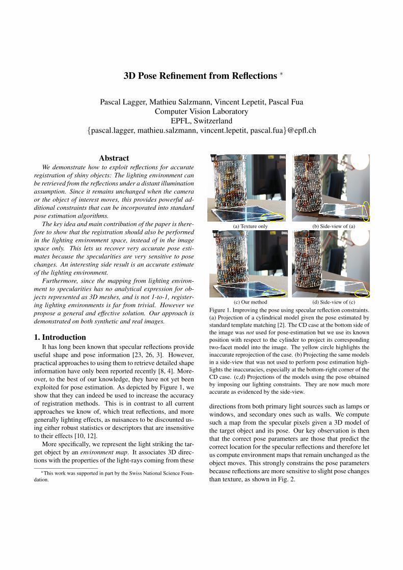
(a) Texture only (b) Side-view of (a)
(c) Our method (d) Side-view of (c)
Figure 1. Improving the pose using specular reflection constraints.
(a) Projection of a cylindrical model given the pose estimated by
standard template matching [2]. The CD case at the bottom side of
the image was not used for pose-estimation but we use its known
position with respect to the cylinder to project its corresponding
two-facet model into the image. The yellow circle highlights the
inaccurate reprojection of the case. (b) Projecting the same models
in a side-view that was not used to perform pose estimation high-
lights the inaccuracies, especially at the bottom-right corner of the
CD case. (c,d) Projections of the models using the pose obtained
by imposing our lighting constraints. They are now much more
accurate as evidenced by the side-view.
directions from both primary light sources such as lamps or
windows, and secondary ones such as walls. We compute
such a map from the specular pixels given a 3D model of
the target object and its pose. Our key observation is then
that the correct pose parameters are those that predict the
correct location for the specular reflections and therefore let
us compute environment maps that remain unchanged as the
object moves. This strongly constrains the pose parameters
because reflections are more sensitive to slight pose changes
than texture, as shown in Fig. 2.
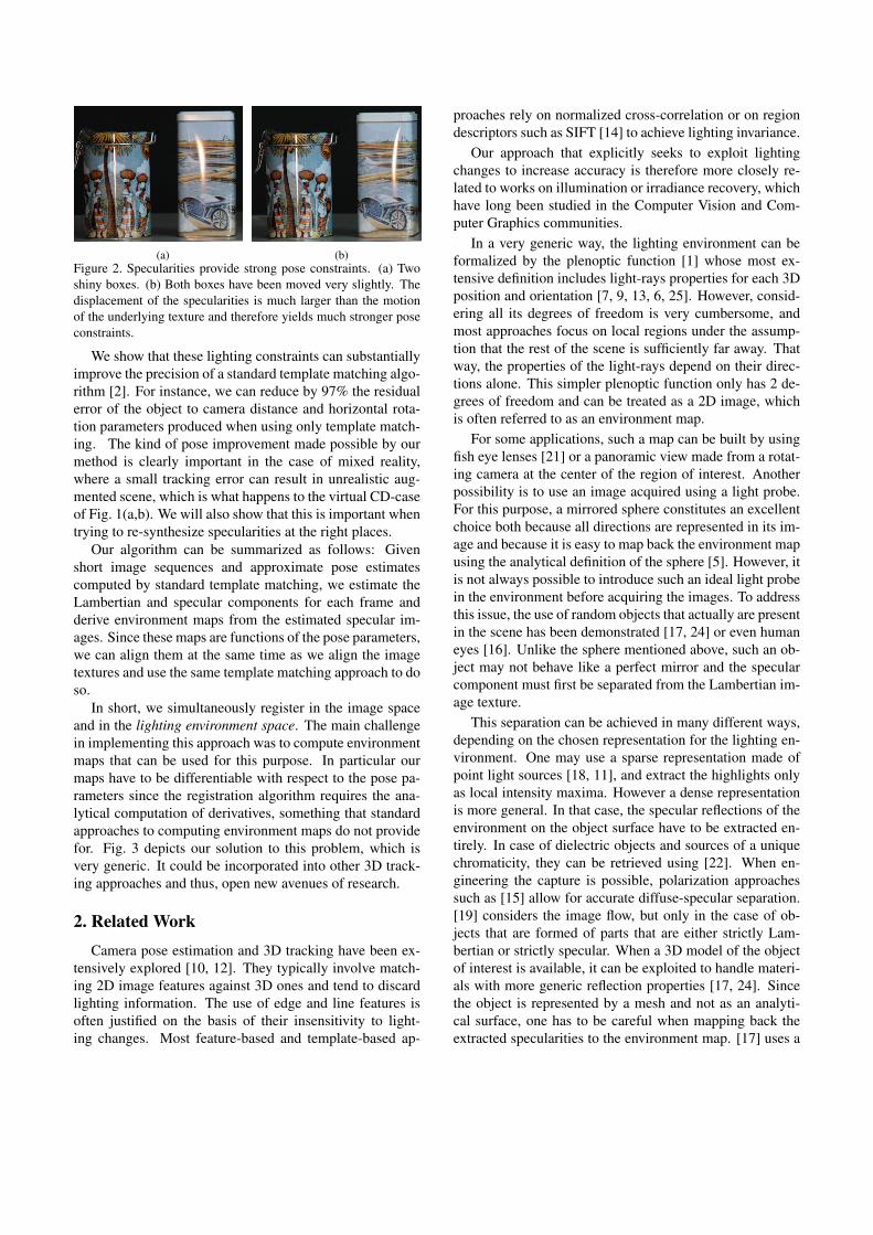
(a) (b)
Figure 2. Specularities provide strong pose constraints. (a) Two
shiny boxes. (b) Both boxes have been moved very slightly. The
displacement of the specularities is much larger than the motion
of the underlying texture and therefore yields much stronger pose
constraints.
We show that these lighting constraints can substantially
improve the precision of a standard template matching algo-
rithm [2]. For instance, we can reduce by 97% the residual
error of the object to camera distance and horizontal rota-
tion parameters produced when using only template match-
ing. The kind of pose improvement made possible by our
method is clearly important in the case of mixed reality,
where a small tracking error can result in unrealistic aug-
mented scene, which is what happens to the virtual CD-case
of Fig. 1(a,b). We will also show that this is important when
trying to re-synthesize specularities at the right places.
Our algorithm can be summarized as follows: Given
short image sequences and approximate pose estimates
computed by standard template matching, we estimate the
Lambertian and specular components for each frame and
derive environment maps from the estimated specular im-
ages. Since these maps are functions of the pose parameters,
we can align them at the same time as we align the image
textures and use the same template matching approach to do
so.
In short, we simultaneously register in the image space
and in the lighting environment space. The main challenge
in implementing this approach was to compute environment
maps that can be used for this purpose. In particular our
maps have to be differentiable with respect to the pose pa-
rameters since the registration algorithm requires the ana-
lytical computation of derivatives, something that standard
approaches to computing environment maps do not provide
for. Fig. 3 depicts our solution to this problem, which is
very generic. It could be incorporated into other 3D track-
ing approaches and thus, open new avenues of research.
2. Related Work
Camera pose estimation and 3D tracking have been ex-
tensively explored [10, 12]. They typically involve match-
ing 2D image features against 3D ones and tend to discard
lighting information. The use of edge and line features is
often justified on the basis of their insensitivity to light-
ing changes. Most feature-based and template-based ap-
proaches rely on normalized cross-correlation or on region
descriptors such as SIFT [14] to achieve lighting invariance.
Our approach that explicitly seeks to exploit lighting
changes to increase accuracy is therefore more closely re-
lated to works on illumination or irradiance recovery, which
have long been studied in the Computer Vision and Com-
puter Graphics communities.
In a very generic way, the lighting environment can be
formalized by the plenoptic function [1] whose most ex-
tensive definition includes light-rays properties for each 3D
position and orientation [7, 9, 13, 6, 25]. However, consid-
ering all its degrees of freedom is very cumbersome, and
most approaches focus on local regions under the assump-
tion that the rest of the scene is sufficiently far away. That
way, the properties of the light-rays depend on their direc-
tions alone. This simpler plenoptic function only has 2 de-
grees of freedom and can be treated as a 2D image, which
is often referred to as an environment map.
For some applications, such a map can be built by using
fish eye lenses [21] or a panoramic view made from a rotat-
ing camera at the center of the region of interest. Another
possibility is to use an image acquired using a light probe.
For this purpose, a mirrored sphere constitutes an excellent
choice both because all directions are represented in its im-
age and because it is easy to map back the environment map
using the analytical definition of the sphere [5]. However, it
is not always possible to introduce such an ideal light probe
in the environment before acquiring the images. To address
this issue, the use of random objects that actually are present
in the scene has been demonstrated [17, 24] or even human
eyes [16]. Unlike the sphere mentioned above, such an ob-
ject may not behave like a perfect mirror and the specular
component must first be separated from the Lambertian im-
age texture.
This separation can be achieved in many different ways,
depending on the chosen representation for the lighting en-
vironment. One may use a sparse representation made of
point light sources [18, 11], and extract the highlights only
as local intensity maxima. However a dense representation
is more general. In that case, the specular reflections of the
environment on the object surface have to be extracted en-
tirely. In case of dielectric objects and sources of a unique
chromaticity, they can be retrieved using [22]. When en-
gineering the capture is possible, polarization approaches
such as [15] allow for accurate diffuse-specular separation.
[19] considers the image flow, but only in the case of ob-
jects that are formed of parts that are either strictly Lam-
bertian or strictly specular. When a 3D model of the object
of interest is available, it can be exploited to handle materi-
als with more generic reflection properties [17, 24]. Since
the object is represented by a mesh and not as an analyti-
cal surface, one has to be careful when mapping back the
extracted specularities to the environment map. [17] uses a
(a) (b) (c) (d)
3d
d2
d1
d3
d2
d1
(e) (f)
d2
3d
6d
d1
d4d5
d6
d5
d4
d2
3d 1d
(g) (h)
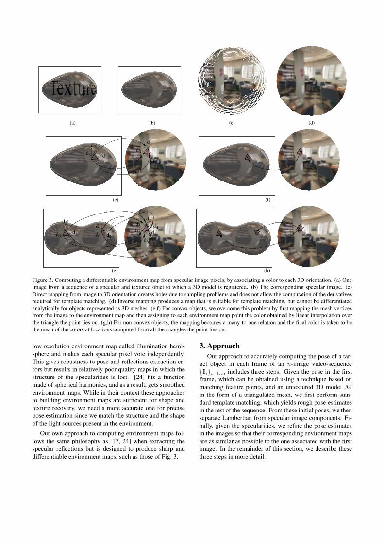
Figure 3. Computing a differentiable environment map from specular image pixels, by associating a color to each 3D orientation. (a) One
image from a sequence of a specular and textured objet to which a 3D model is registered. (b) The corresponding specular image. (c)
Direct mapping from image to 3D orientation creates holes due to sampling problems and does not allow the computation of the derivatives
required for template matching. (d) Inverse mapping produces a map that is suitable for template matching, but cannot be differentiated
analytically for objects represented as 3D meshes. (e,f) For convex objects, we overcome this problem by first mapping the mesh vertices
from the image to the environment map and then assigning to each environment map point the color obtained by linear interpolation over
the triangle the point lies on. (g,h) For non-convex objects, the mapping becomes a many-to-one relation and the final color is taken to be
the mean of the colors at locations computed from all the triangles the point lies on.
low resolution environment map called illumination hemi-
sphere and makes each specular pixel vote independently.
This gives robustness to pose and reflections extraction er-
rors but results in relatively poor quality maps in which the
structure of the specularities is lost. [24] fits a function
made of spherical harmonics, and as a result, gets smoothed
environment maps. While in their context these approaches
to building environment maps are sufficient for shape and
texture recovery, we need a more accurate one for precise
pose estimation since we match the structure and the shape
of the light sources present in the environment.
Our own approach to computing environment maps fol-
lows the same philosophy as [17, 24] when extracting the
specular reflections but is designed to produce sharp and
differentiable environment maps, such as those of Fig. 3.
3. Approach
Our approach to accurately computing the pose of a tar-
get object in each frame of an n-image video-sequence
{Ii}i=1..n includes three steps. Given the pose in the first
frame, which can be obtained using a technique based on
matching feature points, and an untextured 3D model Min the form of a triangulated mesh, we first perform stan-
dard template matching, which yields rough pose-estimates
in the rest of the sequence. From these initial poses, we then
separate Lambertian from specular image components. Fi-
nally, given the specularities, we refine the pose estimates
in the images so that their corresponding environment maps
are as similar as possible to the one associated with the first
image. In the remainder of this section, we describe these
three steps in more detail.
3.1. Initial Pose Estimation
We treat the first image as a reference and perform tem-
plate matching to estimate the pose in the others. More
specifically, given the pose Θ1 in the first image I1, we seek
to recover the pose Θi in the following ones in terms of 3
exponential map coefficients for rotation and 3 translation
parameters. Let W (I,Θ,Θ′) be the function that warps the
image of mesh M with pose Θ in I to synthesize the one
that would have been produced if its pose had been Θ′. We
use barycentric coordinates to select regularly spaced 3D
points on each of the nf facets of M and assign to these
points the intensity corresponding to their reprojection in
image I1 given pose Θ1. We retrieve the pose Θi in image
Ii by maximizing
fT(Θi) =
nf∑
j=1
NCC (W (I1,Θ1,Θi)(pj(Θi)), I(pj(Θi))) , (1)
where the pj are the 2D projections of the 3D points sam-
pled on facet j, and NCC(., .) represents normalized cross-
correlation. Bilinear image interpolation lets us treat fT as
a differentiable function of the pose, which is important for
optimization purposes.
3.2. Isolating Specularities
To extract specularities, we could have used sophisti-
cated methods, such as those proposed [22, 20] for dielec-
tric materials. However, for the sake of both simplicity and
generality, we used a much simpler median-based approach,
which has proved adequate for our purposes.
Because normalized cross-correlation is relatively insen-
sitive to illumination changes, template matching yields
pose estimates that, while not perfectly accurate, are suffi-
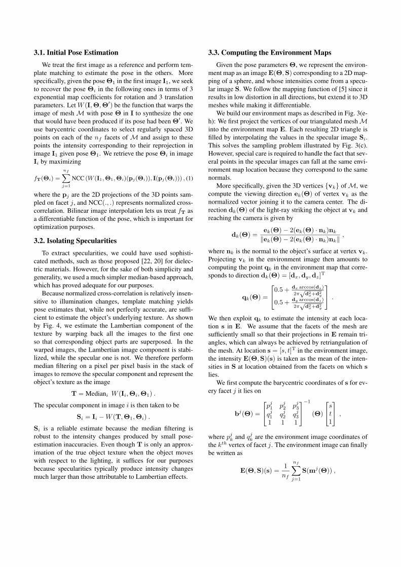
cient to estimate the object’s underlying texture. As shown
by Fig. 4, we estimate the Lambertian component of the
texture by warping back all the images to the first one
so that corresponding object parts are superposed. In the
warped images, the Lambertian image component is stabi-
lized, while the specular one is not. We therefore perform
median filtering on a pixel per pixel basis in the stack of
images to remove the specular component and represent the
object’s texture as the image
T = Mediani W (Ii,Θi,Θ1) .
The specular component in image i is then taken to be
Si = Ii − W (T,Θ1,Θi) .
Si is a reliable estimate because the median filtering is
robust to the intensity changes produced by small pose-
estimation inaccuracies. Even though T is only an approx-
imation of the true object texture when the object moves
with respect to the lighting, it suffices for our purposes
because specularities typically produce intensity changes
much larger than those attributable to Lambertian effects.
3.3. Computing the Environment Maps
Given the pose parameters Θ, we represent the environ-
ment map as an image E(Θ,S) corresponding to a 2D map-
ping of a sphere, and whose intensities come from a specu-
lar image S. We follow the mapping function of [5] since it
results in low distortion in all directions, but extend it to 3D
meshes while making it differentiable.
We build our environment maps as described in Fig. 3(e-
h): We first project the vertices of our triangulated mesh Minto the environment map E. Each resulting 2D triangle is
filled by interpolating the values in the specular image Si.
This solves the sampling problem illustrated by Fig. 3(c).
However, special care is required to handle the fact that sev-
eral points in the specular images can fall at the same envi-
ronment map location because they correspond to the same
normals.
More specifically, given the 3D vertices {vk} of M, we
compute the viewing direction ek(Θ) of vertex vk as the
normalized vector joining it to the camera center. The di-
rection dk(Θ) of the light-ray striking the object at vk and
reaching the camera is given by
dk(Θ) =ek(Θ) − 2(ek(Θ) · nk)nk
‖ek(Θ) − 2(ek(Θ) · nk)nk‖,
where nk is the normal to the object’s surface at vertex vk.
Projecting vk in the environment image then amounts to
computing the point qk in the environment map that corre-
sponds to direction dk(Θ) = [dx,dy,dz]T
qk(Θ) =
0.5 + dx arccos(dz)
2π√
d2x+d2
y
0.5 +dy arccos(dz)
2π√
d2x+d2
y
.
We then exploit qk to estimate the intensity at each loca-
tion s in E. We assume that the facets of the mesh are
sufficiently small so that their projections in E remain tri-
angles, which can always be achieved by retriangulation of
the mesh. At location s = [s, t]T in the environment image,
the intensity E(Θ,S)(s) is taken as the mean of the inten-
sities in S at location obtained from the facets on which s
lies.
We first compute the barycentric coordinates of s for ev-
ery facet j it lies on
bj(Θ) =
pj1 p
j2 p
j3
qj1 q
j2 q
j3
1 1 1
−1
(Θ)
s
t
1
,
where pjk and q
jk are the environment image coordinates of
the kth vertex of facet j. The environment image can finally
be written as
E(Θ,S)(s) =1
nf
nf∑
j=1
S(mj(Θ)) ,
(a) (b) (c) (d)
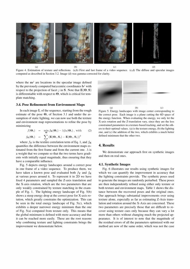
Figure 4. Estimation of texture and reflections. (a,b) First and last frame of a video sequence. (c,d) The diffuse and specular images
computed as described in Section 3.2. Image (d) was gamma-corrected for clarity.
where the mj are locations in the specular image defined
by the previously computed barycentric coordinates bj with
respect to the projection of facet j in S. Note that E(Θ,S)is differentiable with respect to Θ, which is critical for tem-
plate matching.
3.4. Pose Refinement from Environment Maps
In each image Ii of the sequence, starting from the rough
estimate of the pose Θi of Section 3.1 and under the as-
sumption of static lighting, we can now use both the texture
and environment map representations to refine the pose by
minimizing
f(Θi) = minΘ
fE(Θi) − λfT(Θi) , with (2)
fE(Θi) =∑
s
(E(Θi,Si) − E(Θ1,S1))2
where fT is the texture correlation term of Eq. 1, and fE
quantifies the difference between the environment maps es-
timated from the first frame and from the current one. λ is
a weight that we compute so that the two terms have gradi-
ents with initially equal magnitude, thus ensuring that they
have a comparable influence.
Fig. 5 depicts energy landscapes around a correct pose
in one frame of a video sequence. To produce them, we
have taken a known pose and evaluated both fT and fE
at various poses around it. To represent it in 2D we have
fixed 4 parameters and sampled the Z-axis translation and
the X-axis rotation, which are the two parameters that are
only weakly constrained by texture matching in the exam-
ple of Fig. 1. The lighting energy landscape of Fig. 5(b)
shows a steep energy drop at the correct pose for X-axis ro-
tation, which greatly constrains the optimization. This can
be seen in the total energy landscape of Fig. 5(c), which
exhibits a deeper narrower energy minimum than the one
of Fig. 5(a) computed from texture only. This means that
the global minimum is defined with more accuracy and that
it can be reached more easily. These are the root reasons
why combining texture and lighting constraints brings the
improvement we demonstrate below.
(a) (b) (c)
Figure 5. Energy landscapes with image center corresponding to
the correct pose. Each image is a plane cutting the 6D space of
the energy function. When evaluating the energy, we only let the
X-axis rotation and the Z-translation vary, since they are the less
constrained parameters in a texture-based tracking, and set the oth-
ers to their optimal values. (a) is the texture energy, (b) the lighting
one, and (c) the addition of the two, which exhibits a much better
defined minimum that the other two.
4. Results
We demonstrate our approach first on synthetic images
and then on real ones.
4.1. Synthetic Images
Fig. 6 illustrates our results using synthetic images for
which we can quantify the improvement in accuracy that
the lighting constraints provide. The synthetic poses used
to generate the images are randomly perturbed. These poses
are then independently refined using either only texture or
both texture and environment maps. Table 1 shows the dis-
tance between the recovered poses and the original ones.
Our approach brings substantial improvements over using
texture alone, especially as far as estimating Z-Axis trans-
lation and rotation around the X-Axis are concerned. These
two parameters are precisely those that are difficult to re-
cover using texture cues only because they can vary a lot
more than others without changing much the projected ap-
pearance. It is of interest to note that the magnitude of
the residual errors of all the parameters optimized with our
method are now of the same order, which was not the case
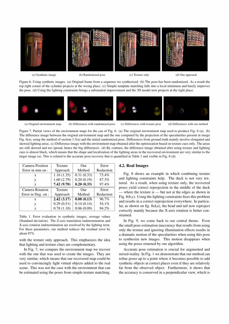
(a) Synthetic image (b) Randomized pose (c) Texture only (d) Our approach
Figure 6. Using synthetic images. (a) Original frame from a sequence we synthesized. (b) The pose has been randomized. As a result the
top right corner of the cylinder projects at the wrong place. (c) Simple template matching falls into a local minimum and barely improves
the pose. (d) Using the lighting constraints brings a substantial improvement and the 3D model now projects at the right place.
(a) Original environment map (b) Differences with randomized pose (c) Differences with texture pose (d) Differences with our method
Figure 7. Partial views of the environment maps for the can of Fig. 6. (a) The original environment map used to produce Fig. 6 (a). (b)
The difference image between the original environment map and the one computed by the projection of the specularities present in image
Fig. 6(a), using the method of section 3.3(a) and the initial randomized pose. Differences from ground truth mainly involve elongated and
skewed lighting areas. (c) Difference image with the environment map obtained after the optimization based on texture cues only. The areas
are still skewed and too spread, hence the big differences. (d) By contrast, the difference image obtained after using texture and lighting
cues is almost black, which means that the shape and localization of the lighting areas in the recovered environment are very similar to the
target image (a). This is related to the accurate pose recovery that is quantified in Table 1 and visible in Fig. 6 (d).
Camera Position Texture Our Error
Error in mm on : Approach Method Reduction
x 1.16 (1.35) 0.31 (0.33) 73.4%
y 1.60 (2.79) 0.20 (0.19) 87.3%
z 7.42 (9.70) 0.20 (0.33) 97.4%
Camera Rotation Texture Our Error
Error in Deg. on : Approach Method Reduction
x 2.42 (3.17) 0.08 (0.13) 96.7%
y 0.29 (0.51) 0.14 (0.14) 54.1%
z 0.78 (1.10) 0.06 (0.09) 94.2%
Table 1. Error evaluation in synthetic images, average values
(Standard deviation). The Z-axis translation indetermination and
X-axis rotation indetermination are resolved by the lighting term.
For these parameters, our method reduces the residual error by
about 97%.
with the texture only approach. This emphasizes the idea
that lighting and texture clues are complementary.
In Fig. 7, we compare the environment map we recover
with the one that was used to create the images. They are
very similar, which means that our recovered map could be
used to convincingly light virtual objects added to the real
scene. This was not the case with the environment that can
be estimated using the poses from simple texture matching.
4.2. Real Images
Fig. 8 shows an example in which combining texture
and lighting constraints help. The duck is not very tex-
tured. As a result, when using texture only, the recovered
poses yield correct reprojection in the middle of the duck
— where the texture is — but not at the edges as shown in
Fig. 8(b,c). Using the lighting constraints fixes this problem
and results in a correct reprojection everywhere. In particu-
lar, as shown on fig. 8(d,e), the head and tail now reproject
correctly mainly because the X-axis rotation is better con-
strained.
In Fig. 9, we come back to our central theme. Even
the small pose-estimation inaccuracy that results from using
only the texture and ignoring illumination effects results in
a dramatic motion of the specularities when using this pose
to synthesize new images. This motion disappears when
using the poses returned by our algorithm.
Accurate pose estimation is crucial for augmented and
mixed-reality. In Fig. 1 we demonstrate that our method can
refine poses up to a point where it becomes possible to add
synthetic objects at correct places even if they are relatively
far from the observed object. Furthermore, it shows that
the accuracy is conserved in a perpendicular view, which is
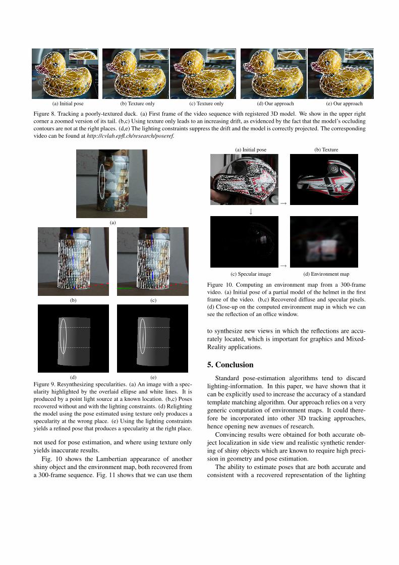
(a) Initial pose (b) Texture only (c) Texture only (d) Our approach (e) Our approach
Figure 8. Tracking a poorly-textured duck. (a) First frame of the video sequence with registered 3D model. We show in the upper right
corner a zoomed version of its tail. (b,c) Using texture only leads to an increasing drift, as evidenced by the fact that the model’s occluding
contours are not at the right places. (d,e) The lighting constraints suppress the drift and the model is correctly projected. The corresponding
video can be found at http://cvlab.epfl.ch/research/poseref.
(a)
(b) (c)
(d) (e)
Figure 9. Resynthesizing specularities. (a) An image with a spec-
ularity highlighted by the overlaid ellipse and white lines. It is
produced by a point light source at a known location. (b,c) Poses
recovered without and with the lighting constraints. (d) Relighting
the model using the pose estimated using texture only produces a
specularity at the wrong place. (e) Using the lighting constraints
yields a refined pose that produces a specularity at the right place.
not used for pose estimation, and where using texture only
yields inaccurate results.
Fig. 10 shows the Lambertian appearance of another
shiny object and the environment map, both recovered from
a 300-frame sequence. Fig. 11 shows that we can use them
(a) Initial pose (b) Texture
→↓
→(c) Specular image (d) Environment map
Figure 10. Computing an environment map from a 300-frame
video. (a) Initial pose of a partial model of the helmet in the first
frame of the video. (b,c) Recovered diffuse and specular pixels.
(d) Close-up on the computed environment map in which we can
see the reflection of an office window.
to synthesize new views in which the reflections are accu-
rately located, which is important for graphics and Mixed-
Reality applications.
5. Conclusion
Standard pose-estimation algorithms tend to discard
lighting-information. In this paper, we have shown that it
can be explicitly used to increase the accuracy of a standard
template matching algorithm. Our approach relies on a very
generic computation of environment maps. It could there-
fore be incorporated into other 3D tracking approaches,
hence opening new avenues of research.
Convincing results were obtained for both accurate ob-
ject localization in side view and realistic synthetic render-
ing of shiny objects which are known to require high preci-
sion in geometry and pose estimation.
The ability to estimate poses that are both accurate and
consistent with a recovered representation of the lighting
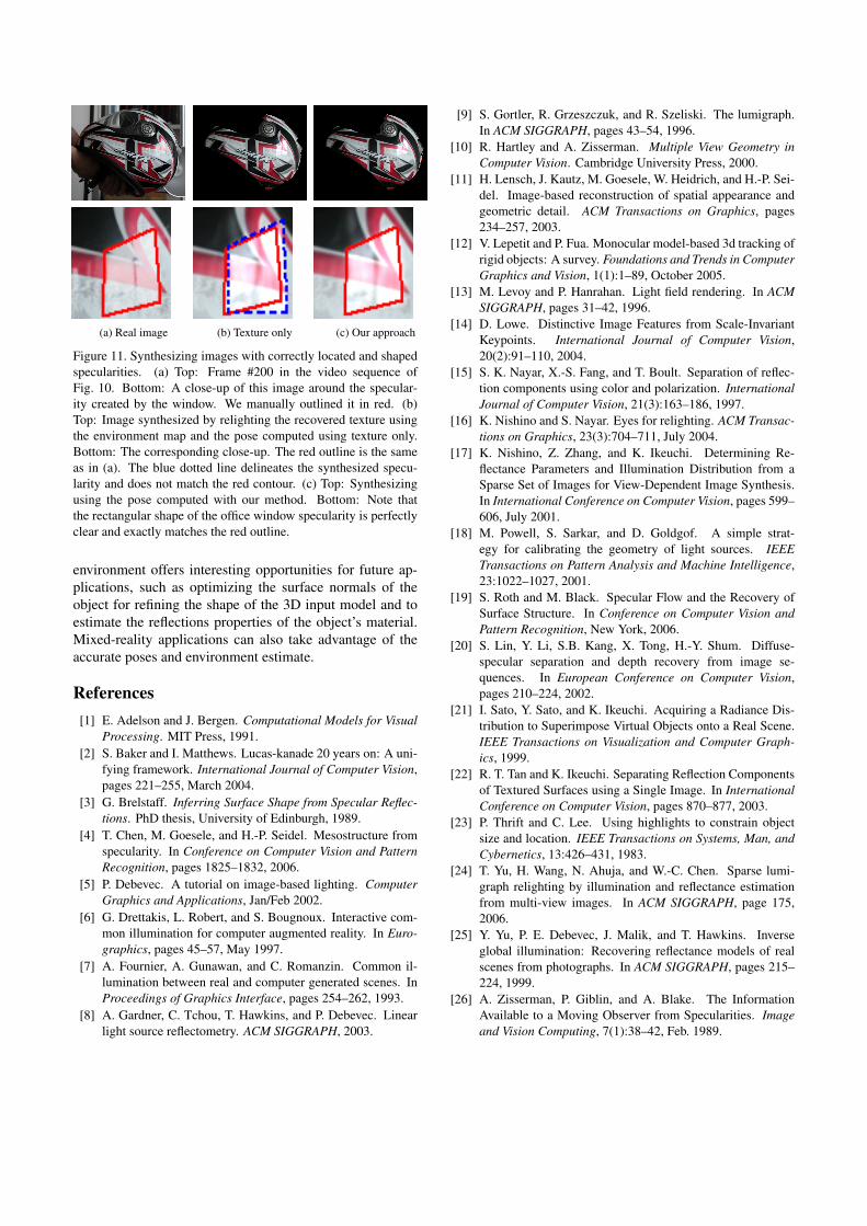
(a) Real image (b) Texture only (c) Our approach
Figure 11. Synthesizing images with correctly located and shaped
specularities. (a) Top: Frame #200 in the video sequence of
Fig. 10. Bottom: A close-up of this image around the specular-
ity created by the window. We manually outlined it in red. (b)
Top: Image synthesized by relighting the recovered texture using
the environment map and the pose computed using texture only.
Bottom: The corresponding close-up. The red outline is the same
as in (a). The blue dotted line delineates the synthesized specu-
larity and does not match the red contour. (c) Top: Synthesizing
using the pose computed with our method. Bottom: Note that
the rectangular shape of the office window specularity is perfectly
clear and exactly matches the red outline.
environment offers interesting opportunities for future ap-
plications, such as optimizing the surface normals of the
object for refining the shape of the 3D input model and to
estimate the reflections properties of the object’s material.
Mixed-reality applications can also take advantage of the
accurate poses and environment estimate.
References
[1] E. Adelson and J. Bergen. Computational Models for Visual
Processing. MIT Press, 1991.
[2] S. Baker and I. Matthews. Lucas-kanade 20 years on: A uni-
fying framework. International Journal of Computer Vision,
pages 221–255, March 2004.
[3] G. Brelstaff. Inferring Surface Shape from Specular Reflec-
tions. PhD thesis, University of Edinburgh, 1989.
[4] T. Chen, M. Goesele, and H.-P. Seidel. Mesostructure from
specularity. In Conference on Computer Vision and Pattern
Recognition, pages 1825–1832, 2006.
[5] P. Debevec. A tutorial on image-based lighting. Computer
Graphics and Applications, Jan/Feb 2002.
[6] G. Drettakis, L. Robert, and S. Bougnoux. Interactive com-
mon illumination for computer augmented reality. In Euro-
graphics, pages 45–57, May 1997.
[7] A. Fournier, A. Gunawan, and C. Romanzin. Common il-
lumination between real and computer generated scenes. In
Proceedings of Graphics Interface, pages 254–262, 1993.
[8] A. Gardner, C. Tchou, T. Hawkins, and P. Debevec. Linear
light source reflectometry. ACM SIGGRAPH, 2003.
[9] S. Gortler, R. Grzeszczuk, and R. Szeliski. The lumigraph.
In ACM SIGGRAPH, pages 43–54, 1996.
[10] R. Hartley and A. Zisserman. Multiple View Geometry in
Computer Vision. Cambridge University Press, 2000.
[11] H. Lensch, J. Kautz, M. Goesele, W. Heidrich, and H.-P. Sei-
del. Image-based reconstruction of spatial appearance and
geometric detail. ACM Transactions on Graphics, pages
234–257, 2003.
[12] V. Lepetit and P. Fua. Monocular model-based 3d tracking of
rigid objects: A survey. Foundations and Trends in Computer
Graphics and Vision, 1(1):1–89, October 2005.
[13] M. Levoy and P. Hanrahan. Light field rendering. In ACM
SIGGRAPH, pages 31–42, 1996.
[14] D. Lowe. Distinctive Image Features from Scale-Invariant
Keypoints. International Journal of Computer Vision,
20(2):91–110, 2004.
[15] S. K. Nayar, X.-S. Fang, and T. Boult. Separation of reflec-
tion components using color and polarization. International
Journal of Computer Vision, 21(3):163–186, 1997.
[16] K. Nishino and S. Nayar. Eyes for relighting. ACM Transac-
tions on Graphics, 23(3):704–711, July 2004.
[17] K. Nishino, Z. Zhang, and K. Ikeuchi. Determining Re-
flectance Parameters and Illumination Distribution from a
Sparse Set of Images for View-Dependent Image Synthesis.
In International Conference on Computer Vision, pages 599–
606, July 2001.
[18] M. Powell, S. Sarkar, and D. Goldgof. A simple strat-
egy for calibrating the geometry of light sources. IEEE
Transactions on Pattern Analysis and Machine Intelligence,
23:1022–1027, 2001.
[19] S. Roth and M. Black. Specular Flow and the Recovery of
Surface Structure. In Conference on Computer Vision and
Pattern Recognition, New York, 2006.
[20] S. Lin, Y. Li, S.B. Kang, X. Tong, H.-Y. Shum. Diffuse-
specular separation and depth recovery from image se-
quences. In European Conference on Computer Vision,
pages 210–224, 2002.
[21] I. Sato, Y. Sato, and K. Ikeuchi. Acquiring a Radiance Dis-
tribution to Superimpose Virtual Objects onto a Real Scene.
IEEE Transactions on Visualization and Computer Graph-
ics, 1999.
[22] R. T. Tan and K. Ikeuchi. Separating Reflection Components
of Textured Surfaces using a Single Image. In International
Conference on Computer Vision, pages 870–877, 2003.
[23] P. Thrift and C. Lee. Using highlights to constrain object
size and location. IEEE Transactions on Systems, Man, and
Cybernetics, 13:426–431, 1983.
[24] T. Yu, H. Wang, N. Ahuja, and W.-C. Chen. Sparse lumi-
graph relighting by illumination and reflectance estimation
from multi-view images. In ACM SIGGRAPH, page 175,
2006.
[25] Y. Yu, P. E. Debevec, J. Malik, and T. Hawkins. Inverse
global illumination: Recovering reflectance models of real
scenes from photographs. In ACM SIGGRAPH, pages 215–
224, 1999.
[26] A. Zisserman, P. Giblin, and A. Blake. The Information
Available to a Moving Observer from Specularities. Image
and Vision Computing, 7(1):38–42, Feb. 1989.