3d-printed wearable backpack stimulator for chronic in
TRANSCRIPT
3D-printed Wearable Backpack Stimulator for Chronic in vivo AquaticStimulation
Graciela Unguez1, Craig Duran2, Delia Valles-Rosales2,
Michael Harris3, Evan Salazar3, Michael McDowell1, Wei Tang4
Abstract— The neural mechanisms underlying changes ingene expression in the interconversion between skeletal muscleand the non-contractile electrogenic cells of the electric organin electric fishes require several days to be manifested. It isextremely challenging to study these non-immediate forms ofplasticity in reduced preparations in cell culture due to thetime requirements. To address this experimental obstacle wedeveloped a 3D-printed wearable backpack that allows chronicelectrical stimulation of aquatic teleost fish. The backpackholds a biphasic simulator using a full H-bridge driver struc-ture. Stimulation amplitude is adjusted with a current sourcecontrolled by a micro potentiometer whereas the stimulationwaveform is reconfigurable through a micro-controller. A 3.7 VLithium Ion Polymer battery powers the entire circuit. Thisbackpack system will allow underwater chronic stimulationexperiments aimed to study the role that neuronal input exertson cell phenotypes in a vertebrate species with high tissueregeneration and cell trans-differentiation capabilities.
Index Terms— Cell Phenotype, Nerve-dependent Gene Regu-lation, Electric Fish, Aquatic Chronic Stimulation, 3D printedBackpack, Spinal Transection.
I. INTRODUCTION
The significance of optimal skeletal muscle performance
for the health and survival of animal organisms is profound.
It is well established that the nervous system is a key regu-
lator of functional properties of fully differentiated skeletal
muscle cells and greatly affects the regeneration of skeletal
muscle following trauma or disease [1]–[7]. However, we
still lack an understanding of how nerve-dependent electrical
activity regulates the plasticity and regeneration of the stri-
ated muscle cell phenotype. Increasing our understanding of
nerve- dependent mechanisms underlying differentiation, re-
differentiation, and trans-differentiation of tissues that occurs
during regeneration is not only critical to understanding the
biology of cell phenotype, but also has important implica-
tions to tissue plasticity and restoration in vertebrates.
Previous research in nerve-dependent regeneration and
plasticity of muscle has focused largely on experimental
*This research was funded by NIH grant 1SC1GM092297- 01A1 (GAU)and NSF INSPIRE Award CNS-1248109 (GAU)
1Graciela Unguez and Michael McDowell are with Department ofBiology, New Mexico State University, Las Cruces, New Mexico, 88003,USA [email protected], [email protected]
2Craig Duran and Delia Valles-Rosales are with Department of IndustryEngineering, New Mexico State University, Las Cruces, New Mexico,88003, USA [email protected], [email protected]
3Michael Harris and Evan Salazar are with Visgence Inc, LasCruces, New Mexico, 88003, USA [email protected],[email protected]
4Wei Tang is with Klipsch School of Electrical and Computer Engineer-ing, New Mexico State University, Las Cruces, New Mexico, 88003, [email protected]
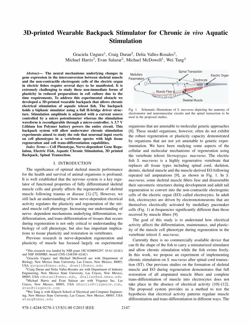
Muscle Fiber
Spinal TransactionElectric Organ
Electrocyte
Skeletal Muscle
Medullary
Pacemakers
Fig. 1. Schematic illustrations of S. macrurus depicting the anatomy ofelectromotor and neuromuscular circuits and the spinal transection to beused in the proposed studies.
organisms that are amenable to molecular genetic approaches
[8]. These model organisms, however, often do not exhibit
the robust regeneration or plasticity capacity demonstrated
by organisms that are not yet amenable to genetic exper-
imentation. We have been studying some aspects of the
cellular and molecular mechanisms of regeneration using
the vertebrate teleost Sternopygus. macrurus. The electric
fish S. macrurus is a highly regenerative vertebrate that
replaces all tissue types including spinal cord, skeleton,
dermis, skeletal muscle and the muscle-derived EO following
repeated tail amputations [9], as shown in Fig. 1. In S.macrurus, some skeletal muscle fibers fuse and disassemble
their sarcomeric structures during development and adult tail
regeneration to convert into the non-contractile electrogenic
cells of the electric organ (EO) called electrocytes. In adult
fish, electrocytes are driven by electromotoneurons that are
themselves electrically activated by medullary pacemaker
cells (Fig. 1) at frequencies significantly different than those
received by muscle fibers [9].
The goal of this study is to understand how electrical
activity affects the differentiation, maintenance, and plastic-
ity of the muscle cell phenotype during regeneration in the
vertebrate teleost S. macrurus.
Currently there is no commercially available device that
can fit the shape of the fish to carry a miniaturized stimulator
and allow chronic stimulation while the fish swims freely.
In this work, we propose an experiment of implementing
chronic stimulation on S. macrurus after spinal cord transec-
tion (ST). Our previous studies on the formation of skeletal
muscle and EO during regeneration demonstrates that full
restoration of all amputated muscle fibers and complete
trans-differentiation of muscle into electrocytes does not
take place in the absence of electrical activity [10]–[12].
The proposed system provides us a method to test the
hypothesis that electrical activity patterns regulate muscle
differentiation and trans-differentiation in different ways. The
978-1-4244-9270-1/15/$31.00 ©2015 IEEE 2147
proposed system consists of a wearable 3D-printed backpack
for the fish equipped the stimulator circuits for chronic
underwater stimulation. This paper is organized as follows.
Section II describes the system design and implementation
considerations. Section III presents the experiment results of
stimulation. Section IV concludes the paper and discusses
future works.
II. SYSTEM DESIGN AND IMPLEMENTATION
In order to study in vivo experiments that provide critical
mechanistic understanding of how skeletal muscle differ-
entiation and regeneration respond to electrical activation
patterns, an interdisciplinary design is introduced. The design
consists of a wearable backpack using 3D-printed prototyp-
ing and an aquatic stimulation circuit. This section describes
design considerations of the proposed system.
A. Stimulator Circuits
To date, chronic in vivo stimulation studies using S.macrurus have proven challenging due to lack of available
experimental hardware for use in aquatic environments. Our
goal is to develop a low-power reconfigurable miniaturized
stimulator that fits in a wearable backpack. In order to pre-
vent harmful electrochemical process, the stimulator should
generate a biphasic stimulation waveform [13]. In such a
waveform, a positive pulse causes activation, followed by a
second pulse with opposite polarity to balance the charge of
the first pulse [14]. A short time delay is necessary between
the two pulses in order to produce an action potential, as
shown in Fig 2 (a). Parameters need to be adjusted in
such waveforms include pulse width w, pulse amplitude a,
distance between two positive pulses d, and distance between
positive and negative pulses p. An alternative stimulation
waveform uses an extended anodic pulse with reduced ampli-
tude to compensate for charge distribution and reduce fatigue
[15], as shown in Fig 2 (b). This waveform requires more
parameters since there are different pulse widths (wp and
wn) and pulse amplitudes (ap and an) for both positive and
negative pulses.
a p
w
0
Am
plit
ud
e
Time
w
a
d
(a)
ap p
wp
0 Time
d
(b)
wnan
Am
plit
ud
e
Fig. 2. Stimulator waveforms (a) Biphasic waveform (b) Extended anodicpulse. In this work we uses the biphasic waveform.
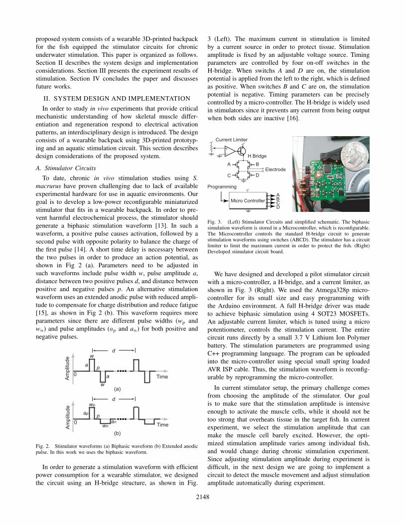
In order to generate a stimulation waveform with efficient
power consumption for a wearable stimulator, we designed
the circuit using an H-bridge structure, as shown in Fig.
3 (Left). The maximum current in stimulation is limited
by a current source in order to protect tissue. Stimulation
amplitude is fixed by an adjustable voltage source. Timing
parameters are controlled by four on-off switches in the
H-bridge. When switchs A and D are on, the stimulation
potential is applied from the left to the right, which is defined
as positive. When switches B and C are on, the stimulation
potential is negative. Timing parameters can be precisely
controlled by a micro-controller. The H-bridge is widely used
in stimulators since it prevents any current from being output
when both sides are inactive [16].
Current Limiter
H Bridge
A B
C D
Micro Controller
ABCD
Programming
Electrode
Fig. 3. (Left) Stimulator Circuits and simplified schematic. The biphasicsimulation waveform is stored in a Microcontroller, which is reconfigurable.The Microcontroller controls the standard H-bridge circuit to generatestimulation waveforms using switches (ABCD). The stimulator has a circuitlimiter to limit the maximum current in order to protect the fish. (Right)Developed stimulator circuit board.
We have designed and developed a pilot stimulator circuit
with a micro-controller, a H-bridge, and a current limiter, as
shown in Fig. 3 (Right). We used the Atmega328p micro-
controller for its small size and easy programming with
the Arduino environment. A full H-bridge driver was made
to achieve biphasic simulation using 4 SOT23 MOSFETs.
An adjustable current limiter, which is tuned using a micro
potentiometer, controls the stimulation current. The entire
circuit runs directly by a small 3.7 V Lithium Ion Polymer
battery. The stimulation parameters are programmed using
C++ programming language. The program can be uploaded
into the micro-controller using special small spring loaded
AVR ISP cable. Thus, the stimulation waveform is reconfig-
urable by reprogramming the micro-controller.
In current stimulator setup, the primary challenge comes
from choosing the amplitude of the stimulator. Our goal
is to make sure that the stimulation amplitude is intensive
enough to activate the muscle cells, while it should not be
too strong that overheats tissue in the target fish. In current
experiment, we select the stimulation amplitude that can
make the muscle cell barely excited. However, the opti-
mized stimulation amplitude varies among individual fish,
and would change during chronic stimulation experiment.
Since adjusting stimulation amplitude during experiment is
difficult, in the next design we are going to implement a
circuit to detect the muscle movement and adjust stimulation
amplitude automatically during experiment.
2148
B. 3D-printed Backpack
A fish backpack is designed to host the stimulator circuit
and battery on the target fish without creating excessive stress
on the animal [17]. This entails a lightweight device which
has the similar density of water without metal, since metal
affects EO. The backpack must be adjustable to fit individual
fish and provide mounting place for the stimulator electrode.
The backpack should be firmly attached on fish and should
not slide-off when fish is swimming. The backpack contains
a waterproof circuit case and a battery case to host the
stimulator circuit and battery. The case should be waterproof,
light weighted, and allow for wires to travel from the inside
to the outside of the case while remaining waterproof. In
order to realize the backpack design, we applied rapid
prototyping using three dimensional (3D) computer aided
design (CAD) and 3D printing.
In order to design the backpack, a 3D model of the target
fish is created by measuring its physical size. The 3D model
of the fish is created based on an airfoil shape midsections
with adjusted height and width. The measurements were
used in Unigraphics NX 8.5 to create a 3D model of the
midsection of the fish. The model was used as a basis of
conceptualization on creating the backpack.
Fig. 4. (Left) Design of 3D model fish backpack and enclosure for circuitcase. Similar enclosure for battery on a parallel bar is not shown. (Right)Anesthetized fish getting fitted with a backpack.
The fish backpack consists of two rings to attach it on
the fish body, and two sidebars connecting the rings while
hosting the circuit case and the battery case. Fig. 4 shows
the design of the backpack. The design of the rings was
based on the 3D model of the fish midsection. The rings
were printed using a 25% infill, 0.25mm layer height, 230 C
nozzle temperatures, with 1 shell at 40 mm/s printing speed.
The next step is to measure distance from the front ring to the
rear ring, which creates an optimal fit on the fishs body. The
fish was sedated so that it could be removed from the tank,
and the rings were slid onto the body until they fit snugly
at each end. A flexible ruler was then used to measure the
distance between the two rings. A measurement was also
taken from the tip of the nose to adjust the ring size better
for that point on the body. A different filament was also
used in the manufacturing of the rings because the standard
Polylactic Acid (PLA) was too rigid and exerted chafing to
the fish skin. Hence, MakerBot Flexible PLA was chosen as
the material for its softer and more flexible properties, while
retaining the non-hazardous properties of the standard PLA.
The overall mass of the dual ring system is 5.77 grams.
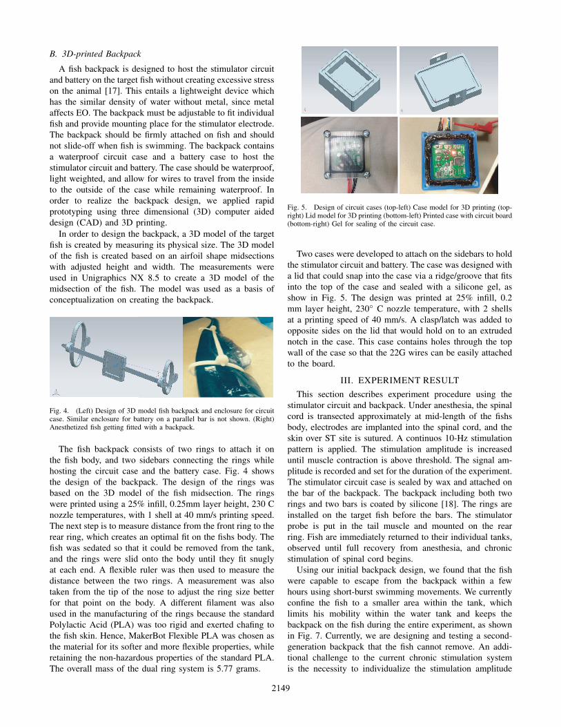
Fig. 5. Design of circuit cases (top-left) Case model for 3D printing (top-right) Lid model for 3D printing (bottom-left) Printed case with circuit board(bottom-right) Gel for sealing of the circuit case.
Two cases were developed to attach on the sidebars to hold
the stimulator circuit and battery. The case was designed with
a lid that could snap into the case via a ridge/groove that fits
into the top of the case and sealed with a silicone gel, as
show in Fig. 5. The design was printed at 25% infill, 0.2
mm layer height, 230◦ C nozzle temperature, with 2 shells
at a printing speed of 40 mm/s. A clasp/latch was added to
opposite sides on the lid that would hold on to an extruded
notch in the case. This case contains holes through the top
wall of the case so that the 22G wires can be easily attached
to the board.
III. EXPERIMENT RESULT
This section describes experiment procedure using the
stimulator circuit and backpack. Under anesthesia, the spinal
cord is transected approximately at mid-length of the fishs
body, electrodes are implanted into the spinal cord, and the
skin over ST site is sutured. A continuos 10-Hz stimulation
pattern is applied. The stimulation amplitude is increased
until muscle contraction is above threshold. The signal am-
plitude is recorded and set for the duration of the experiment.
The stimulator circuit case is sealed by wax and attached on
the bar of the backpack. The backpack including both two
rings and two bars is coated by silicone [18]. The rings are
installed on the target fish before the bars. The stimulator
probe is put in the tail muscle and mounted on the rear
ring. Fish are immediately returned to their individual tanks,
observed until full recovery from anesthesia, and chronic
stimulation of spinal cord begins.
Using our initial backpack design, we found that the fish
were capable to escape from the backpack within a few
hours using short-burst swimming movements. We currently
confine the fish to a smaller area within the tank, which
limits his mobility within the water tank and keeps the
backpack on the fish during the entire experiment, as shown
in Fig. 7. Currently, we are designing and testing a second-
generation backpack that the fish cannot remove. An addi-
tional challenge to the current chronic stimulation system
is the necessity to individualize the stimulation amplitude
2149
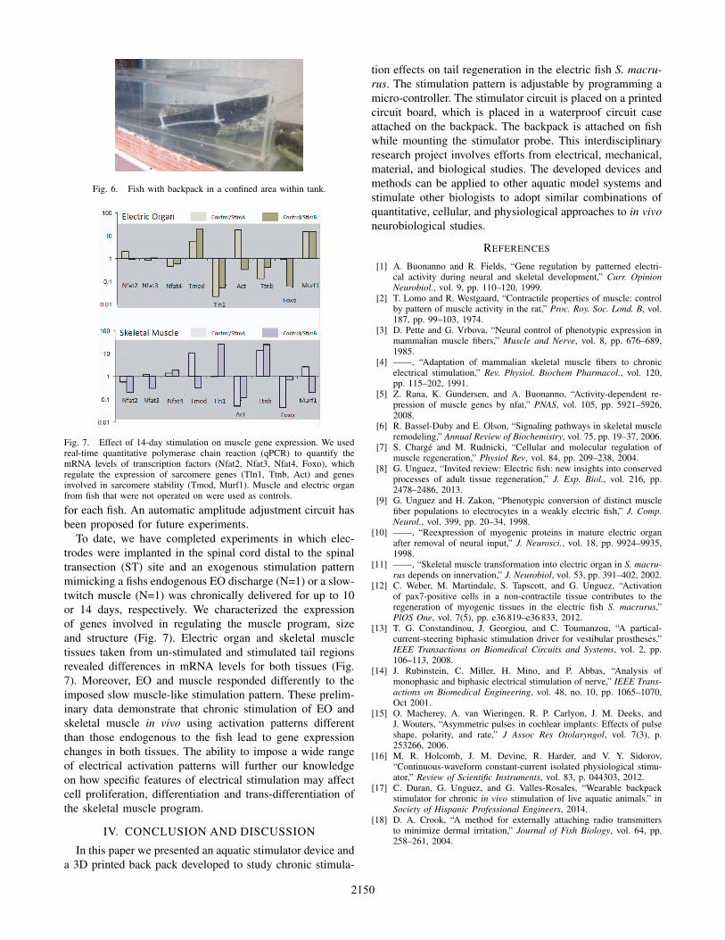
Fig. 6. Fish with backpack in a confined area within tank.
Fig. 7. Effect of 14-day stimulation on muscle gene expression. We usedreal-time quantitative polymerase chain reaction (qPCR) to quantify themRNA levels of transcription factors (Nfat2, Nfat3, Nfat4, Foxo), whichregulate the expression of sarcomere genes (Tln1, Ttnb, Act) and genesinvolved in sarcomere stability (Tmod, Murf1). Muscle and electric organfrom fish that were not operated on were used as controls.
for each fish. An automatic amplitude adjustment circuit has
been proposed for future experiments.
To date, we have completed experiments in which elec-
trodes were implanted in the spinal cord distal to the spinal
transection (ST) site and an exogenous stimulation pattern
mimicking a fishs endogenous EO discharge (N=1) or a slow-
twitch muscle (N=1) was chronically delivered for up to 10
or 14 days, respectively. We characterized the expression
of genes involved in regulating the muscle program, size
and structure (Fig. 7). Electric organ and skeletal muscle
tissues taken from un-stimulated and stimulated tail regions
revealed differences in mRNA levels for both tissues (Fig.
7). Moreover, EO and muscle responded differently to the
imposed slow muscle-like stimulation pattern. These prelim-
inary data demonstrate that chronic stimulation of EO and
skeletal muscle in vivo using activation patterns different
than those endogenous to the fish lead to gene expression
changes in both tissues. The ability to impose a wide range
of electrical activation patterns will further our knowledge
on how specific features of electrical stimulation may affect
cell proliferation, differentiation and trans-differentiation of
the skeletal muscle program.
IV. CONCLUSION AND DISCUSSION
In this paper we presented an aquatic stimulator device and
a 3D printed back pack developed to study chronic stimula-
tion effects on tail regeneration in the electric fish S. macru-rus. The stimulation pattern is adjustable by programming a
micro-controller. The stimulator circuit is placed on a printed
circuit board, which is placed in a waterproof circuit case
attached on the backpack. The backpack is attached on fish
while mounting the stimulator probe. This interdisciplinary
research project involves efforts from electrical, mechanical,
material, and biological studies. The developed devices and
methods can be applied to other aquatic model systems and
stimulate other biologists to adopt similar combinations of
quantitative, cellular, and physiological approaches to in vivoneurobiological studies.
REFERENCES
[1] A. Buonanno and R. Fields, “Gene regulation by patterned electri-cal activity during neural and skeletal development,” Curr. OpinionNeurobiol., vol. 9, pp. 110–120, 1999.
[2] T. Lomo and R. Westgaard, “Contractile properties of muscle: controlby pattern of muscle activity in the rat,” Proc. Roy. Soc. Lond. B, vol.187, pp. 99–103, 1974.
[3] D. Pette and G. Vrbova, “Neural control of phenotypic expression inmammalian muscle fibers,” Muscle and Nerve, vol. 8, pp. 676–689,1985.
[4] ——, “Adaptation of mammalian skeletal muscle fibers to chronicelectrical stimulation,” Rev. Physiol. Biochem Pharmacol., vol. 120,pp. 115–202, 1991.
[5] Z. Rana, K. Gundersen, and A. Buonanno, “Activity-dependent re-pression of muscle genes by nfat,” PNAS, vol. 105, pp. 5921–5926,2008.
[6] R. Bassel-Duby and E. Olson, “Signaling pathways in skeletal muscleremodeling,” Annual Review of Biochemistry, vol. 75, pp. 19–37, 2006.
[7] S. Charge and M. Rudnicki, “Cellular and molecular regulation ofmuscle regeneration,” Physiol Rev, vol. 84, pp. 209–238, 2004.
[8] G. Unguez, “Invited review: Electric fish: new insights into conservedprocesses of adult tissue regeneration,” J. Exp. Biol., vol. 216, pp.2478–2486, 2013.
[9] G. Unguez and H. Zakon, “Phenotypic conversion of distinct musclefiber populations to electrocytes in a weakly electric fish,” J. Comp.Neurol., vol. 399, pp. 20–34, 1998.
[10] ——, “Reexpression of myogenic proteins in mature electric organafter removal of neural input,” J. Neurosci., vol. 18, pp. 9924–9935,1998.
[11] ——, “Skeletal muscle transformation into electric organ in S. macru-rus depends on innervation,” J. Neurobiol, vol. 53, pp. 391–402, 2002.
[12] C. Weber, M. Martindale, S. Tapscott, and G. Unguez, “Activationof pax7-positive cells in a non-contractile tissue contributes to theregeneration of myogenic tissues in the electric fish S. macrurus,”PlOS One, vol. 7(5), pp. e36 819–e36 833, 2012.
[13] T. G. Constandinou, J. Georgiou, and C. Toumanzou, “A partical-current-steering biphasic stimulation driver for vestibular prostheses,”IEEE Transactions on Biomedical Circuits and Systems, vol. 2, pp.106–113, 2008.
[14] J. Rubinstein, C. Miller, H. Mino, and P. Abbas, “Analysis ofmonophasic and biphasic electrical stimulation of nerve,” IEEE Trans-actions on Biomedical Engineering, vol. 48, no. 10, pp. 1065–1070,Oct 2001.
[15] O. Macherey, A. van Wieringen, R. P. Carlyon, J. M. Deeks, andJ. Wouters, “Asymmetric pulses in cochlear implants: Effects of pulseshape, polarity, and rate,” J Assoc Res Otolaryngol, vol. 7(3), p.253266, 2006.
[16] M. R. Holcomb, J. M. Devine, R. Harder, and V. Y. Sidorov,“Continuous-waveform constant-current isolated physiological stimu-ator,” Review of Scientific Instruments, vol. 83, p. 044303, 2012.
[17] C. Duran, G. Unguez, and G. Valles-Rosales, “Wearable backpackstimulator for chronic in vivo stimulation of live aquatic animals.” inSociety of Hispanic Professional Engineers, 2014.
[18] D. A. Crook, “A method for externally attaching radio transmittersto minimize dermal irritation,” Journal of Fish Biology, vol. 64, pp.258–261, 2004.
2150