3d printing of electro mechanical systems · this paper describes the fabrication of a high current...
TRANSCRIPT
3D Printing of Electro Mechanical Systems
Efrain Aguilera1,2, Jorge Ramos1,3, David Espalin1, Fernando Cedillos1,3,
Dan Muse5, Ryan Wicker1,3, Eric MacDonald1,2
1. W.M. Keck Center for 3D Innovation, University of Texas at El Paso, TX 79968 USA
2. Electrical and Computer Engineering, University of Texas at El Paso, TX 79968 USA
3. Mechanical Engineering, University of Texas at El Paso, TX 79968 USA
4. Materials Science and Engineering, University of Texas at El Paso, TX 79968 USA
5. Printed Device Concepts, LLC, 500 W. Overland, El Paso, TX 79901 USA
Abstract
Recent research has focused on the fabrication freedom of 3D printing to not only create
conceptual models but final end-use products as well. By democratizing the manufacturing
process, products will inevitably be fabricated locally and with unit-level customization. For 3D
printed end-use products to be profoundly meaningful, the fabrication technologies will be
required to enhance the structures with additional features such as electromechanical content. In
the last decade, several research groups have reported embedding electronic components and
electrical interconnect into 3D printed structures during process interruptions. However, to date
there appears to be an absence of fabricated devices with electromechanical functionality in which
moving parts with electronic control have been created within a single Additive Manufacturing
(AM) build sequence. Moreover, previously reported 3D printed electronics were limited by the
use of conductive inks, which serve as electrical interconnect and are commonly known for
inadequate conductivity. This paper describes the fabrication of a high current (>1 amp)
electromechanical device through a single hybrid AM build sequence using a uPrint Plus, a
relatively low cost 3D. Additionally, a novel integrated process for embedding high performance
conductors directly into the thermoplastic FDM substrate is demonstrated. By avoiding low
conductivity inks, high power electromechanical applications are enabled such as 3D printed
robotics, UAVs and biomedical devices.
Index Terms— Additive Manufacturing; 3D Printed Electronics; 3D Printed Electromechancial devices; hybrid
manufacturing; Structural Electronics
I. INTRODUCTION
Additive Manufacturing (AM) (more popularly referred to as 3D printing) is a form of
manufacturing in which a Computer Aided Design (CAD) model is captured and then subsequently
fabricated layer-by-layer. The AM technology used to create the electromechanical part described
in this paper is a polymer extrusion-based process – in which a thermoplastic material is extruded
through a heated nozzle to provide a robust polymer substrate – in the end fabricating an object
that is customized without the requirement for tooling. Although the process is useful for
fabricating mechanical parts such as custom fixtures or molds, the shapes are relegated to simple
mechanical objects. Recent research has shifted focus into increasing the functionality of AM-
fabricated parts through the integration of electronic components and interconnects into 3D printed
950
devices [1-6]; however, reports of freeform fabricated electromechanical devices are limited. In
[7], AM technology was used to build a simple electrostatic biocompatible actuator with a service
life of two to three actuation cycles, this displays a clear interest in increasing functionality of AM
parts. Concurrently to and independently of this work, a cleverly designed 3D printed stepper
motor has surfaced in pop culture [8], but the fabricated parts required a final assembly process
and could have been easily fabricated with traditional manufacturing. Consequently, the example
does not take advantage of having access to individual layers during a build with AM and seems
to offer no significant advantage in AM other than the reduction in amortizable cost of the initial
units by eliminating expensive tooling. The University of Texas at El Paso (UTEP) is exploring
the fabrication of fully electromechanical devices fabricated in a single build sequence that
includes an AM technology with process interruptions allowing for the robotic placement of
components (microcontrollers, magnets and other electronic control circuits) to create multi-
functional 3D printed structures.
The advantages of a 3D printed electromechanical device such as a motor – fabricated in
one single build sequence as opposed to an assembly process - is the ability to apply the benefits
of 3D printing (unit level customization) to not just mechanical parts but also electronic and
electromechanical parts within larger customized systems such as a robot or UAV. When each
fabrication can be unit-level customized as required for the final application, the possibility exists
to fabricate objects that conform to human anatomy or to provide rapid deployment of a specific
UAV system. Other benefits include the ability to provide geometric complexity for free -
fabricating structures that cannot be built in any other technology (e.g. internal cavities or meshes).
Additionally, by adapting the placement and orientation of the electronics within the final envelope
of the design, volumetric efficiency can be dramatically improved.
II. Previous Work
Recently, reports in literature describing 3D printing with embedded electronics have been
growing. The combination of Direct Printing (DP) of conductive inks onto 3D printed structures
was introduced by Palmer [9] and expanded in Medina [10] and Lopes [11] in which simple circuits
were implemented to demonstrate functionality by integrating a dispensing system into a
stereolithography (SL) machine using three-dimensional linear stages with a dispensing head. This
approach included a demonstration of a simple prototype temperature sensor with nine components
including a 555-timer chip. Navarrete [12] describes improvements to using DP on AM substrates
by introducing channels into the substrate for the conductive material in order to provide
delineation of the electrical lines and allow for the reduction of line width and spacing while
simultaneously reducing the possibility of line-to-line shorting. Line pitch was thus determined
by the precision of the SL fabrication (e.g. laser beam size) rather than the dispensing process with
lower spatial resolution. 3D printed electronics can conform to any shape providing a unique
advantage over mundane electrical systems and one example of exploiting the 3D design freedom
is illustrated in a CubeSat called Trailblazer, which will be launched into low Earth orbit in late
2013. One of the elements of this small satellite is a 3D printed UV curable substrate with
embedded electronics, including a microcontroller, gyroscope, crystal, and several passive
components (e.g. capacitors and resistors) [13].
Though advancements regarding the process of DP electrical interconnects integrated into
951

3D printed structures were described and have contributed to the advancement of low power
applications, such as magnetometers or six-sided gaming dice, the research to date described
electronics that do not require electric currents exceeding 100mA. In these low power cases, the
conductive ink interconnects are sufficient in terms of conductivity. However, the application
described in this paper requires electric currents that can reach 5 amps and possibly higher, which
required an appropriately sized or capable current carrying conductor. A patent pending process
developed at UTEP in which solid metal conductors can be embedded into 3D printed
thermoplastic structures provides electrical interconnect with sufficiently high current density
capabilities for the presented demonstration [13] – similar to the conductivity provided by
traditional Printed Circuit Boards (PCB).
III. Fabrication
Although many AM technologies exists today that are capable of producing metal, ceramic
or plastic substrates, an extrusion-based AM process that deposits thermoplastics was selected to
create the 3-Phase DC motor due to ease of access to the build chamber, the low cost of operation,
the durability of the thermoplastics and the simplicity of the build process. The goal of this line
of research is to eventually allow consumers to download an electro-mechanical or electronic
design from the internet (such as a cell phone or toy car) and 3D print a fully functional device in
the comfort of their own home, or alternatively, to allow NASA to manufacture space hardware on
the International Space Station or a lunar colony. Plastic extrusion AM uses commercial grade
thermoplastics – providing for the fabrication of durable substrates. Additionally a sacrificial
support material is used that can be removed in an ultrasonic bath to allow for overhanging
substrate features. The AM machine selected to create the 3-Phase motor was a uPrint Plus
manufactured by Stratasys (retail price of approximately $20k) and the material used was ABSplus
- the material provided by Stratasys [14]. Consequently, this paper demonstrates that
electromechanical devices can be fabricated with relative inexpensive printers and that printing
multi-functionality is not limited to expensive commercial-grade AM systems. This capability is
fertile for exploration and optimization by the Do It Yourself (DIY) community.
The main goal of this demonstration, however, is to illustrate the potential for multi-
technology fabrication, which is currently under development at the W. M. Keck Center for 3D
Innovation. Whereas the demonstration described in this paper was completed (1) with an
inexpensive commercial system, and (2) with interruptions introduced for the manual insertion of
components and electrical interconnects, the ultimate objective of this course of research is to
fabricate a motor in a completely automated fashion with a novel multi-technology AM system
(multi3D). The demonstration illustrates what is possible to fabricate when multiple manufacturing
techniques are integrated together. With contemporary AM providing the base fabrication process
for a dielectric substrate, a comprehensive manufacturing suite is being integrated seamlessly to
include 1) extrusion of a wide variety of robust thermoplastics/metals, 2) micromachining, 3) laser
ablation, 4) embedding of wires and fine-pitch meshes submerged within the thermoplastics and
5) component placement. Collectively, the integrated technologies will be capable of fabricating
multi-material structures through the integration of a wide variety of manufacturing systems
(multi-technology) to provide multi-functional products (consumer wearable electronics, bio-
medical devices, defense, space and energy systems, electromechanical devices etc.).
952
IV. Design and Build Process
The freedom of design provided by AM technologies allows a unique approach for
conformal electromechanical devices. For example, the presented electric motor could be
fabricated in the form of a conical shape if the intended use is in the nose of an airplane, or
alternatively, mounting brackets could be designed onto the motor increasing the freedom of device
placement within a large system on a case-by-case basis. This paper describes the process in which
a 3-Phase brushless DC motor is constructed in a single build sequence, including a rotor inside a
stator separated by two single row ball bearings that serve to maintain alignment between the two
structures and allow the rotor to rotate freely within the stator. Designing electromechanical parts
requires a more complex design representation using CAD when compared to a simple mechanical
form, due to the concomitant mechanical and electronic features. These simultaneous features
require both mechanical and electrical CAD methodologies and the confluence of both was
completed manually in this example. Future work includes a unified methodology in which 3D
printed electronics could be designed with a high degree of freedom component placement and
routing within arbitrary forms.
The first complication faced when using a uPrint Plus was the lack of available options and
control over the rastering and support material. This includes no option for at-will addition or
removal of support in the design to be printed. Whereas in some AM system, the user has arbitrary
control over the use of support, design rules had to be implemented in the uPrint design to avoid
post-processing and other complications associated with the support material. Eliminating the
need for support is important when building internal features since access for support removal may
be difficult or impossible. In the case of the presented single motor build, moving internal
structures and electronic components were encapsulated during the build process, and
consequently, the support cannot be easily removed after fabrication. The removal process
involves an ultrasonic bath, where the device is submerged and heated in water for several hours
until all the sacrificial material has been dissolved. If water-soluble support material is required
to enable internal overhanging structural features and is subsequently removed in an ultrasonic
bath after fabrication, electronic components cannot be included in the substrate prior to this post-
process step. The minimum angle to avoid the automatic placement of support in the uPrint Plus’s
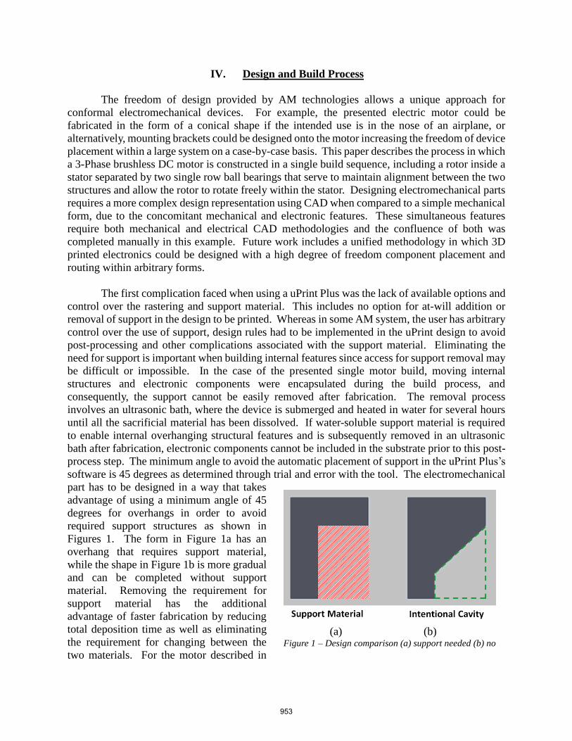
software is 45 degrees as determined through trial and error with the tool. The electromechanical
part has to be designed in a way that takes
advantage of using a minimum angle of 45
degrees for overhangs in order to avoid
required support structures as shown in
Figures 1. The form in Figure 1a has an
overhang that requires support material,
while the shape in Figure 1b is more gradual
and can be completed without support
material. Removing the requirement for
support material has the additional
advantage of faster fabrication by reducing
total deposition time as well as eliminating
the requirement for changing between the
two materials. For the motor described in
(a) (b) Figure 1 – Design comparison (a) support needed (b) no
support needed
953
this paper, the only support material used was for the base of the motor.
An alternative approach is to use different STL file processing software (e.g. Insight) that
allows for complete control over placement and removal of support material. Normally, the uPrint
Plus’s proprietary software automatically places support material to serve temporarily to form a
cavity, but for design cases like the one described in this paper, where components are being
embedded, the user can identify that the cavity will be filled with a component rather than maintain
free space and that once embedded can double as support material. This allows for material to be
dispensed over the component and subsequently continue the build. Direct control of deposition
of the support material allows the user to evaluate each cavity and decide if a component is present
and will act as support. The lack of additional control provided by the uPrint Plus software led to
the implementation of 45 degrees to indirectly avoid support material and allow for cavities inside
the device where components can be embedded.
A further complication of the 3-Phase motor is that this application requires high electric
currents depending on performance and power requirements and was designed to be able to
consume up to 10 amps at 12 volts; however similarly sized motors on the market can reach up to
120 amps or more. Initial versions of the UTEP AM motors have been fabricated using electrical
interconnects dispensed using a Direct-Write (DW) method for conductive inks - typically
consisting of a silver-based ink suspended in a binder. These types of printed interconnects have
very low conductivity due to the restrictions imposed by the plastic substrate on the curing
temperatures. Conductive inks generally cannot handle high current densities (>0.02mA/um2)
where 150 mA fused a printed line of approximately 250 um width and 10 um thickness – as
opposed to 40 gauge wire at 1.5 mA/um2 [15]. When used to connect the electronics and
electromagnets of the motor, printed lines were destroyed due to high current densities required
and became open circuits – resulting initially in unreliable operation and ultimately in system
failure. Therefore the use of conductive inks was not possible. Alternatively, a patent pending
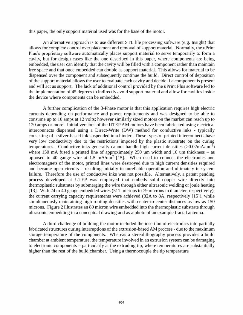
process developed at UTEP was employed that embeds solid copper wire directly into
thermoplastic substrates by submerging the wire through either ultrasonic welding or joule heating
[13]. With 24 to 40 gauge embedded wires (511 microns to 79 microns in diameter, respectively),
the current carrying capacity requirements were achieved (32A to 8A, respectively [15]), while
simultaneously maintaining high routing densities with center-to-center distances as low as 150
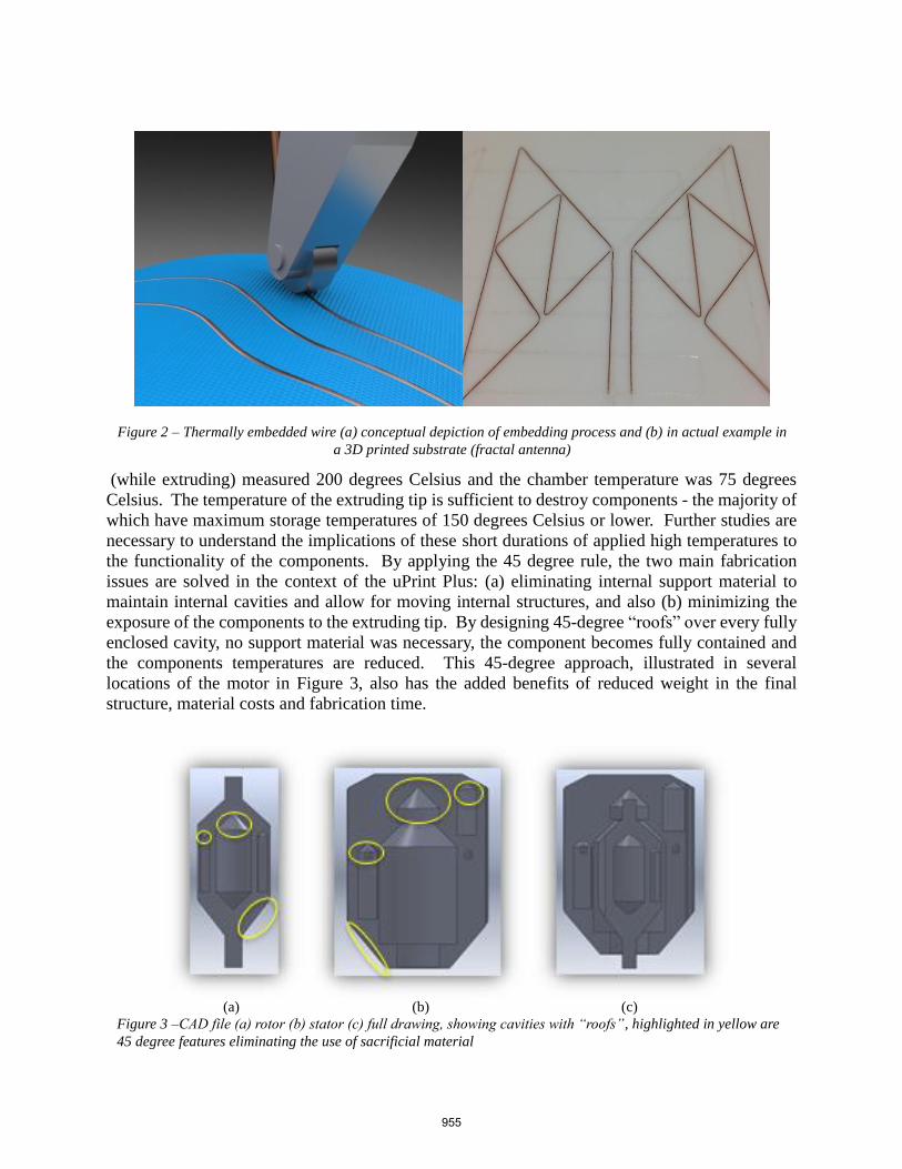
microns. Figure 2 illustrates an 80 micron wire embedded into the thermoplastic substrate through
ultrasonic embedding in a conceptual drawing and as a photo of an example fractal antenna.
A third challenge of building the motor included the insertion of electronics into partially
fabricated structures during interruptions of the extrusion-based AM process - due to the maximum
storage temperature of the components. Whereas a stereolithography process provides a build
chamber at ambient temperature, the temperature involved in an extrusion system can be damaging
to electronic components – particularly at the extruding tip, where temperatures are substantially
higher than the rest of the build chamber. Using a thermocouple the tip temperature
954
(while extruding) measured 200 degrees Celsius and the chamber temperature was 75 degrees
Celsius. The temperature of the extruding tip is sufficient to destroy components - the majority of
which have maximum storage temperatures of 150 degrees Celsius or lower. Further studies are
necessary to understand the implications of these short durations of applied high temperatures to
the functionality of the components. By applying the 45 degree rule, the two main fabrication
issues are solved in the context of the uPrint Plus: (a) eliminating internal support material to
maintain internal cavities and allow for moving internal structures, and also (b) minimizing the
exposure of the components to the extruding tip. By designing 45-degree “roofs” over every fully
enclosed cavity, no support material was necessary, the component becomes fully contained and
the components temperatures are reduced. This 45-degree approach, illustrated in several
locations of the motor in Figure 3, also has the added benefits of reduced weight in the final
structure, material costs and fabrication time.
Figure 2 – Thermally embedded wire (a) conceptual depiction of embedding process and (b) in actual example in
a 3D printed substrate (fractal antenna)
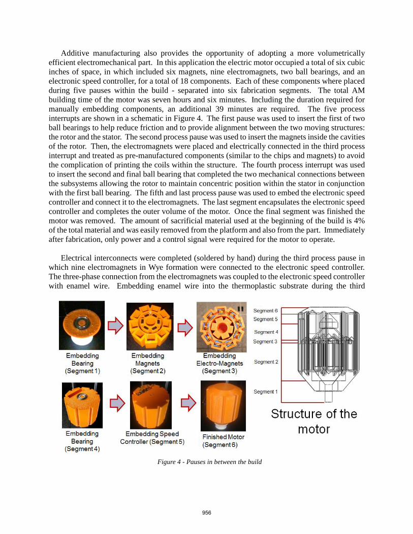
(a) (b) (c)
Figure 3 –CAD file (a) rotor (b) stator (c) full drawing, showing cavities with “roofs”, highlighted in yellow are
45 degree features eliminating the use of sacrificial material
955
Additive manufacturing also provides the opportunity of adopting a more volumetrically
efficient electromechanical part. In this application the electric motor occupied a total of six cubic
inches of space, in which included six magnets, nine electromagnets, two ball bearings, and an
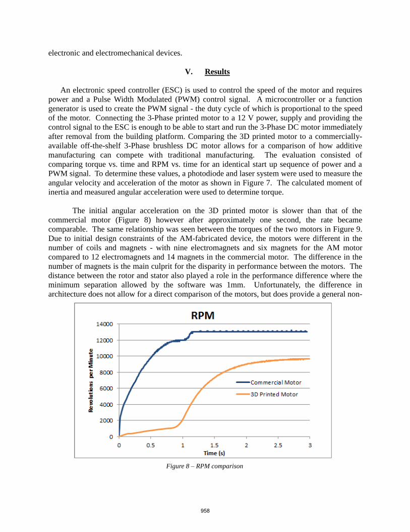
electronic speed controller, for a total of 18 components. Each of these components where placed
during five pauses within the build - separated into six fabrication segments. The total AM
building time of the motor was seven hours and six minutes. Including the duration required for
manually embedding components, an additional 39 minutes are required. The five process
interrupts are shown in a schematic in Figure 4. The first pause was used to insert the first of two
ball bearings to help reduce friction and to provide alignment between the two moving structures:
the rotor and the stator. The second process pause was used to insert the magnets inside the cavities
of the rotor. Then, the electromagnets were placed and electrically connected in the third process
interrupt and treated as pre-manufactured components (similar to the chips and magnets) to avoid
the complication of printing the coils within the structure. The fourth process interrupt was used
to insert the second and final ball bearing that completed the two mechanical connections between
the subsystems allowing the rotor to maintain concentric position within the stator in conjunction
with the first ball bearing. The fifth and last process pause was used to embed the electronic speed
controller and connect it to the electromagnets. The last segment encapsulates the electronic speed
controller and completes the outer volume of the motor. Once the final segment was finished the
motor was removed. The amount of sacrificial material used at the beginning of the build is 4%
of the total material and was easily removed from the platform and also from the part. Immediately
after fabrication, only power and a control signal were required for the motor to operate.
Electrical interconnects were completed (soldered by hand) during the third process pause in
which nine electromagnets in Wye formation were connected to the electronic speed controller.
The three-phase connection from the electromagnets was coupled to the electronic speed controller
with enamel wire. Embedding enamel wire into the thermoplastic substrate during the third
Figure 4 - Pauses in between the build
956

process interrupt provided the additional benefit of maintaining the position of the components
during subsequent fabrication. The enamel dielectric avoided shorts between lines as the wires
shared a single channel in the substrate. These channels also provided a flush, planar surface to
continue thermoplastic deposition as seen in Figure 5. Connections were then hand soldered on
the final pause to the electronic speed controller completing the circuit. As described in Section
2, a system under development (multi3D) will provide the automation of a range of integrated
manufacturing technologies such as laser welding systems for a solderless and automated
component connection solution. An example of a laser-welded component is shown Figure 6.
Implementing a YAG laser micro-welding system from Miyachi Unitek [16] within a custom
machine like the Multi3D is the subject of ongoing work for the fully automated fabrication of
Figure 7 - Testing set-up
Figure 5 –Electromagnets embedded Figure 6 – Micro-Welding with YAG laser
957
electronic and electromechanical devices.
V. Results
An electronic speed controller (ESC) is used to control the speed of the motor and requires
power and a Pulse Width Modulated (PWM) control signal. A microcontroller or a function
generator is used to create the PWM signal - the duty cycle of which is proportional to the speed
of the motor. Connecting the 3-Phase printed motor to a 12 V power, supply and providing the
control signal to the ESC is enough to be able to start and run the 3-Phase DC motor immediately
after removal from the building platform. Comparing the 3D printed motor to a commercially-
available off-the-shelf 3-Phase brushless DC motor allows for a comparison of how additive
manufacturing can compete with traditional manufacturing. The evaluation consisted of
comparing torque vs. time and RPM vs. time for an identical start up sequence of power and a
PWM signal. To determine these values, a photodiode and laser system were used to measure the
angular velocity and acceleration of the motor as shown in Figure 7. The calculated moment of
inertia and measured angular acceleration were used to determine torque.
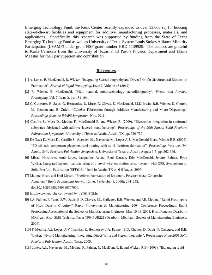
The initial angular acceleration on the 3D printed motor is slower than that of the
commercial motor (Figure 8) however after approximately one second, the rate became
comparable. The same relationship was seen between the torques of the two motors in Figure 9.
Due to initial design constraints of the AM-fabricated device, the motors were different in the
number of coils and magnets - with nine electromagnets and six magnets for the AM motor
compared to 12 electromagnets and 14 magnets in the commercial motor. The difference in the
number of magnets is the main culprit for the disparity in performance between the motors. The
distance between the rotor and stator also played a role in the performance difference where the
minimum separation allowed by the software was 1mm. Unfortunately, the difference in
architecture does not allow for a direct comparison of the motors, but does provide a general non-
Figure 8 – RPM comparison
958

0
qualitative evaluation. Future work includes fabricating a motor that is identical to a commercial
system at least in terms of number of internal components for a more direct comparison.
VI. Conclusion/Future Work
An electromechanical device was fabricated with 3D printing and functionality was
demonstrated. Using relatively inexpensive commercially available equipment, printing of
electronic and electromechanical devices is possible in remote places such as space or battlefields
where no readily available inventory is in stock – or by the DIY community. Inevitably, even
consumers will be able to download printable design files representing an electronic device, and
subsequently, 3D print the device within their own home.
Though manual intervention was used in this example to build an electromechanical device, this
system demonstrated the potential of what can be fabricated with a multi-material and multi-
technology 3D printer. Current work includes seamlessly integrating several manufacturing
technologies into a single system (Multi3D) including multiple polymer extrusion technologies,
micro-machining, wire embedding, pick and place and micro-welding. Once complete,
electromechanical systems such as the demonstration piece described in this paper will be
fabricated in a single build sequence without manual intervention. Eliminating human
involvement will allow for improved manufacturing tolerances and simplicity of fabrication and
eventually will enable a “press print” methodology where one can start a fabrication of a CAD
design and return to a new functional device the next morning.
Acknowledgements
The research presented here was conducted at The University of Texas at El Paso within
the W.M. Keck Center for 3D Innovation (Keck Center). Through funding from the State of Texas
Figure 9 – Torque comparison
959
1
Emerging Technology Fund, the Keck Center recently expanded to over 13,000 sq. ft., housing
state-of-the-art facilities and equipment for additive manufacturing processes, materials, and
applications. Specifically, this research was supported by funding from the State of Texas
Emerging Technology Fund as well as University of Texas System Louis Stokes Alliance Minority
Participation (LSAMP) under grant NSF grant number HRD-1139929. The authors are grateful
to Karla Carmona from the University of Texas at El Paso’s Physics Department and Elaine
Maestas for their participation and contribution.
References
[1] A. Lopes, E. MacDonald, R. Wicker, “Integrating Stereolithography and Direct Print for 3D Structural Electronics
Fabrication”, Journal of Rapid Prototyping, Issue 2, Volume 18 (2012).
[2] R. Wicker, E. MacDonald, “Multi-material, multi-technology stereolithography”, Virtual and Physical
Prototyping, Vol. 7. Issue 3, pp. 181-194.
[3] C. Gutierrez, R. Salas, G. Hernandez, D. Muse, R. Olivas, E. MacDonald, M.D. Irwin, R.B. Wicker, K. Church,
M. Newton and B. Zufelt, “CubeSat Fabrication through Additive Manufacturing and Micro-Dispensing,”
Proceedings from the IMAPS Symposium, Nov. 2011.
[4] Castillo S., Muse D., Medina F., MacDonald E. and Wicker R. (2009), “Electronics integration in conformal
substrates fabricated with additive layered manufacturing”, Proceedings of the 20th Annual Solid Freeform
Fabrication Symposium, University of Texas at Austin, Austin, TX, pp. 730-737.
[5] De Nava E., Muse D., Castillo S., Alawneh M., Navarrete M., Lopes A.J., MacDonald E. and Wicker R.B. (2008),
“3D off-axis component placement and routing with solid freeform fabrication”, Proceedings from the 19th
Annual Solid Freeform Fabrication Symposium, University of Texas at Austin, August 3-5, pp. 362-369.
[6] Misael Navarrete, Amit Lopes, Jacqueline Acuna, Raul Estrada, Eric MacDonald, Jeremy Palmer, Ryan
Wicker, Integrated layered manufacturing of a novel wireless motion sensor system with GPS, Symposium on
Solid Freeform Fabrication (SFF)(18th) held in Austin, TX on 6-8 August 2007.
[7] Malone, Evan, and Hod Lipson. “Freeform Fabrication of Ionomeric Polymer-metal Composite
Actuators.” Rapid Prototyping Journal 12, no. 5 (October 1, 2006): 244–253.
doi:10.1108/13552540610707004.
[8] http://www.youtube.com/watch?v=paT63-8DLbs
[9] J.A. Palmer, P. Yang, D.W. Davis, B.D. Chavez, P.L. Gallegos, R.B. Wicker, and F.R. Medina, “Rapid Prototyping
of High Density Circuitry,” Rapid Prototyping & Manufacturing 2004 Conference Proceedings, Rapid
Prototyping Association of the Society of Manufacturing Engineers, May 10-13, 2004, Hyatt Regency Dearborn,
Michigan. Also, SME Technical Paper TP04PUB221 (Dearborn, Michigan: Society of Manufacturing Engineers,
2004).
[10] F. Medina, A.J. Lopes, A.V. Inamdar, R. Hennessey, J.A. Palmer, B.D. Chavez, D. Davis, P. Gallegos, and R.B.
Wicker, “Hybrid Manufacturing: Integrating Direct-Write and Stereolithography”, Proceedings of the 2005 Solid
Freeform Fabrication, Austin, Texas, 2005.
[11] Lopes, A.J., Navarrete, M., Medina, F., Palmer, J., MacDonald, E. and Wicker, R.B. (2006), “Expanding rapid
960

2
prototyping for electronic systems integration of arbitrary form”, Proceedings of the 17th Annual Solid
Freeform Fabrication Symposium, University of Texas at Austin, Austin, TX.
[12] M. Navarrete, A.J. Lopes, J. Acuna, R. Estrada, E. MacDonald, J.A. Palmer, and R.B. Wicker “Integrated
Layered Manufacturing of a Novel Wireless Motion Sensor with GPS,” Proceedings from the 18th Annual Solid
Freeform Fabrication Symposium, University of Texas at Austin, August 06-08, 2007.
[13] David Espalin, Danny W. Muse, Frank Medina, Eric MacDonald, Ryan B. Wicker, (forthcoming) “3D Printing
Multi-Functionality: Structures with Electronics”, International Journal of Advance Manufacturing Technology
[14] http://www.stratasys.com/
[15] Douglas Brooks, "Fusing Current: When Traces Melt Without a Trace", December 1998
[16] http://www.miyachiunitek.com/
961