3d-printing with thermoplastics and continuous …
TRANSCRIPT

Symposium Lightweight Design in Product Development 2018 (LWD-PD18) Zurich, Switzerland, 14th–15th June 2018
3D-PRINTING WITH THERMOPLASTICS AND CONTINUOUS CARBON FIBER M. Titze1, B.T. Kletz2 and J. Riemenschneider3 Institute of Composite Structures and Adaptive Systems, German Aerospace Center (DLR), Brunswick, Germany. [email protected], [email protected], [email protected] 1. INTRODUCTION
Using standard filaments and standard fibers is key to enable industrial scale 3D-printing with continuous carbon fiber reinforcement. The novel printing head for Additive Composite Structures (AddCompSTM) serves this task as one element along the completely new developed process chain for continuous fiber reinforced 3D-printing. Both the AddCompS printing head and the process chain are described within this paper. 2. PRINTING HEAD DESIGN
The design of the printing head offers the opportunity to process standard fiber materials in conjunction with up to three different thermoplastics. The developed manufacturing process is based on the Fused Filament Fabrication (FFF) technology and serves the need for additive manufacturing of three dimensional, fiber reinforced, multi-material, lightweight structures. To establish a robust printing process, several innovations focus on the routing of the standard fibers as well as the thermal management of the printing head and of the generated structure.
The fiber is automatically pulled into the printing head due to its adhesion to the thermoplastic melt during the extrusion. To ensure an adequate feeding of the fiber it is essential to reduce its friction within the printing head, guard the fiber from sharp edges and prevent small bending radiuses. Another challenge is the development of a valve which allows the fiber to get in contact with the melt, but prevents the melted plastics from infiltrating the valve. This is solved by an optimized geometry of the contact zone between fiber and thermoplastic melt supported by centrally supplied compressed air along the fiber routing. The concept is outlined in Figure 1. The thermoplastic melt flow is redirected along a specially shaped needle, so that the flow is forced alongside the extrusion direction. Assisted by a low pressurization of the needle the fiber is routed into the melted plastic while preventing the melt from rising into the needle.
Besides the routing of the fiber, the thermal design of the printing head is crucial for a reliable printing process. This is assured by realizing a sharp temperature gradient between the zone of filament feeding and the melting zone. Preceding investigations using different types of conventional heatbreaks manufactured from aluminium or titanium showed unsatisfactory results. For this reason a new concept is developed and shown in Figure 1. A 1 mm to 3 mm thick calcium silicate glassfiber reinforced plate serves as thermal insulation between the cool feeding zone and the hot melting zone. The temperature gradient is further increased by an actively cooled body directly attached to the insulation plate. Long term measurements indicated a temperature of 45 °C directly above the insulation plate while the temperature of the melting zone is 220 °C. The printing head, the cooling body and the thermal insulation plate are aligned during assembly with a tool to guarantee an edge free channel for the filament routing. To also process materials like PEEK the printing head is able to provide melting temperatures of up to 450 °C. This is addressed by utilizing two cartridge heaters with a total heat power of 400 W, which also enable the system to precisely control the temperature distribution and rapidly react to changing environmental influences.
With the aim of high quality results the impregnation of the fiber as well as the adhesion of the fiber to the matrix and the thermal management of the printed structure needs to be considered. The adhesion as well as the process stability is improved by preheating the fiber before it gets in contact with the melted plastics. It is of major importance the fiber is not damaged during this process step. Other points to address are the printing bed temperature, the temperature of the preceding printed structure to properly bond the new extruded material and the general cooling of the structure to prevent internal stress concentrations or distortions. Another challenge is to prevent the fiber from being pulled out from its desired position during high speeds, sharp curvature movements or real three-dimensional trajectories. For that purpose an adaptive cooling system, which acts directly below the extrusion nozzle on the extruded material, is installed at the printing head. In dependence of the process parameters like the extrusion speed of the printing head or the movement speed and the movement history of the kinematic system, this device allows to set up customable fluid mass flows from different directions to precisely control the temperature distribution of the extruded material. This enables the manufacturing system to print sharp curves or three-dimensional structures without support while assuring an accurate placed fiber.

M. Titze, B.T. Kletz and J. Riemenschneider
Fig. 1: Printing Head Design
3. ADDITIVE MANUFACTURING PROCESS For a successful implementation of a process chain from a CAD model to an additive manufactured three-
dimensional continuous fiber reinforced structure, it is necessary to innovate in different fields of activities. First, the printing head technology itself needs to be developed as described before. Second, there needs to be a process integration which combines the printing head technology, a kinematic system, a control system und the required sensor system. As a third point, the design methodology needs to be defined, considering the specific requirements of the printing head in conjunction with the kinematic system. Design rules have to be formulated and restrictive boundary conditions need to be known. This can only be done, if, as a fourth topic, the material development and material characterization in dependence of the process parameters are accounted. As a last fifth working area, mechanisms for an inline quality assurance during the printing process are required. This creates the potential to monitor the printing process and react dynamically to deviations. By simultaneously addressing these work areas, a robust additive manufacturing system for generating continuous fiber reinforced structures is developed.
The translation of a virtual model to a real structure demands multiple work steps. First of all the design of the CAD model needs to be done in compliance with the design methodology which is defined by the provided additive manufacturing system. Afterwards the numerical model can be compiled for its manufacturing with the kinematic system. Thus, the information of the trajectories to build the structure is stored. For that purpose a software tool is developed, capable to directly translate CATIA CAD models into G-code, to plan the path movements of the kinematic system. The current software version is able to handle structures with a three-dimensional closed polygon base layer and arbitrary thickness. The next step contains the insertion of the printing parameters according to the planned movements like nozzle temperature, filament feeding rate or adaptive cooling of specific trajectory sections. Subsequent the required fiber and thermoplastic materials are loaded into the manufacturing system. Using a central control unit, the created printing job is executed. Additionally a quality control of the generated structure is conducted.
As a first step the described process chain is used to manufacture test specimen for material characterizations as well as real three-dimensional structures. The focus is on the optimization of the printing parameters for different material combinations. This includes PLA, PC, PEI, PEEK as thermoplastics and different types of fibers like twisted yarn or standard and special coated rovings with a size from 3K up to 24K. These materials are used to print test specimen with different ply orientations to characterize them mechanically. Further surveys address cooling profiles for the adaptive cool system. Different parameter settings for the cooling of edges and for the realization of three-dimensional structures without support are explored. In addition the inline quality assurance system is developed further by collecting and evaluating process data. This is assisted by the development of numerical models to simulate critical process steps and analyze the collected process data.
M. Titze, B.T. Kletz and J. Riemenschneider 4. OUTLOOK
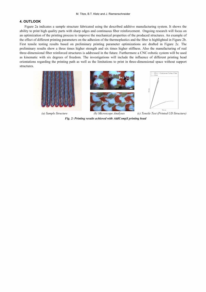
Figure 2a indicates a sample structure fabricated using the described additive manufacturing system. It shows the ability to print high quality parts with sharp edges and continuous fiber reinforcement. Ongoing research will focus on an optimization of the printing process to improve the mechanical properties of the produced structures. An example of the effect of different printing parameters on the adhesion of the thermoplastics and the fiber is highlighted in Figure 2b. First tensile testing results based on preliminary printing parameter optimizations are drafted in Figure 2c. The preliminary results show a three times higher strength and six times higher stiffness. Also the manufacturing of real three-dimensional fiber reinforced structures is addressed in the future. Furthermore a CNC-robotic system will be used as kinematic with six degrees of freedom. The investigations will include the influence of different printing head orientations regarding the printing path as well as the limitations to print in three-dimensional space without support structures.
(a) Sample Structure (b) Microscope Analyses (c) Tensile Test (Printed UD Structure) Fig. 2: Printing results achieved with AddCompS printing head