3d soil modelling (geometry) - midasadmin.midasuser.com/uploadfiles2/webinar/midas gts...3d soil...
TRANSCRIPT
Page 1 of 9
3D Soil Modelling (Geometry)
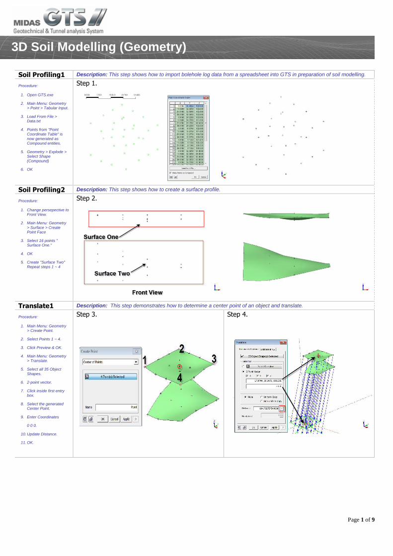
Soil Profiling1 Description: This step shows how to import bolehole log data from a spreadsheet into GTS in preparation of soil modelling.
Procedure:
1. Open GTS.exe
2. Main Menu: Geometry > Point > Tabular Input.
3. Load From File > Data.txt
4. Points from "Point Coordinate Table" is now generated as Compound entities.
5. Geometry > Explode > Select Shape (Compound)
6. OK
Step 1.
Soil Profiling2 Description: This step shows how to create a surface profile.
Procedure:
1. Change persepective to Front View.
2. Main Menu: Geometry > Surface > Create Point Face
3. Select 16 points " Surface One."
4. OK
5. Create "Surface Two" Repeat steps 1 ~ 4
Step 2.
Translate1 Description: This step demonstrates how to determine a center point of an object and translate.
Procedure:
1. Main Menu: Geometry > Create Point.
2. Select Points 1 ~ 4.
3. Click Preview & OK.
4. Main Menu: Geometry > Translate.
5. Select all 35 Object Shapes.
6. 2-point vector.
7. Click inside first entry box.
8. Select the generated Center Point.
9. Enter Coordinates
0 0 0.
10. Update Distance.
11. OK.
Step 3.
Step 4.
Page 2 of 9
3D Soil Modelling (Geometry)
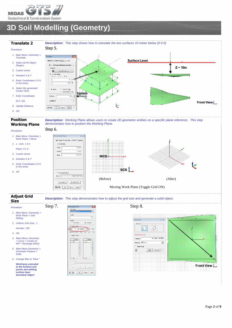
Translate 2 Description: This step shows how to translate the two surfaces 10 meter below (0 0 0)
Procedure:
1. Main Menu: Geometry > Translate.
2. Select all 35 Object Shapes.
3. 2-point vector.
4. Deselect X & Y
5. Enter Coordinates 0 0 0 in first entry.
6. Select the generated Center Point.
7. Enter Coordinates
(0 0 -10).
8. Update Distance.
9. OK.
Step 5.
Position
Working Plane Description: Working Plane allows users to create 2D geometric entities on a specific plane reference. This step demonstrates how to position the Working Plane.
Procedure:
1. Main Menu: Geometry > Work Plane > Move.
2. x - Axis: 1 0 0
Plane: 0 1 0
3. 2-point vector.
4. Deselect X & Y
5. Enter Coordinates 0 0 0 in first entry.
6. OK
Step 6.
Adjust Grid Size
Description: This step demonstrates how to adjust the grid size and generate a solid object.
Procedure:
1. Main Menu: Geometry > Work Plane > Grid Setting.
2. Uniform Grid Size : 1
Number: 100
3. OK.
4. Main Menu: Geometry > Curve > Create on WP > Rectange (Wire)
5. Main Menu:Geometry > Generator Feature > Solid.
6. Change filter to "Wire."
Wireframe extended to the furthest end points and withing surface layer boundary edges!
Step 7.
Step 8.
(Before) (After)
Moving Work Plane (Toggle Grid ON)
Page 3 of 9
3D Soil Modelling (Geometry)
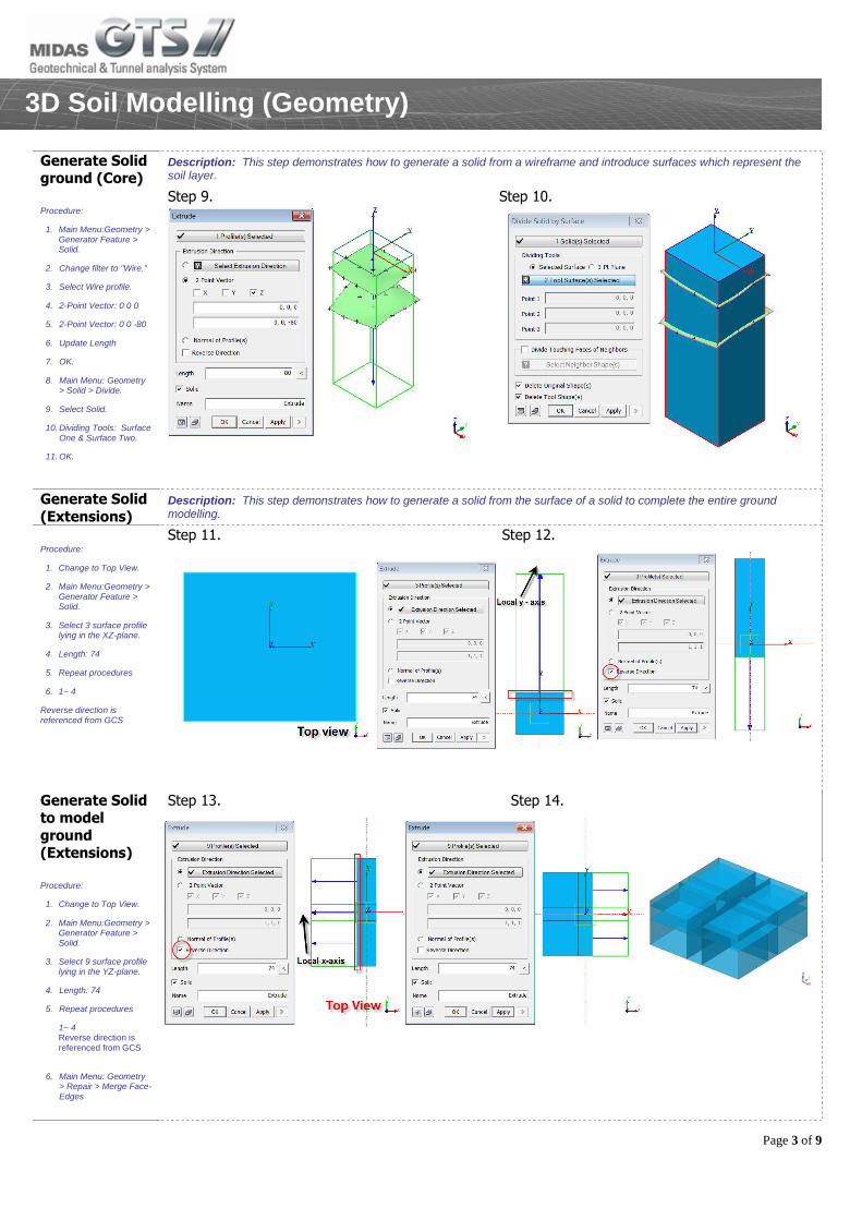
Generate Solid ground (Core)
Description: This step demonstrates how to generate a solid from a wireframe and introduce surfaces which represent the soil layer.
Procedure:
1. Main Menu:Geometry > Generator Feature > Solid.
2. Change filter to "Wire."
3. Select Wire profile.
4. 2-Point Vector: 0 0 0
5. 2-Point Vector: 0 0 -80
6. Update Length
7. OK.
8. Main Menu: Geometry > Solid > Divide.
9. Select Solid.
10. Dividing Tools: Surface One & Surface Two.
11. OK.
Step 9.
Step 10.
Generate Solid
(Extensions) Description: This step demonstrates how to generate a solid from the surface of a solid to complete the entire ground modelling.
Procedure:
1. Change to Top View.
2. Main Menu:Geometry > Generator Feature > Solid.
3. Select 3 surface profile lying in the XZ-plane.
4. Length: 74
5. Repeat procedures
6. 1~ 4
Reverse direction is referenced from GCS
Step 11. Step 12.
Generate Solid to model
ground (Extensions)
Step 13. Step 14.
Procedure:
1. Change to Top View.
2. Main Menu:Geometry > Generator Feature > Solid.
3. Select 9 surface profile lying in the YZ-plane.
4. Length: 74
5. Repeat procedures
1~ 4 Reverse direction is referenced from GCS
6. Main Menu: Geometry > Repair > Merge Face-Edges
Page 4 of 9
3D Soil Modelling (Geometry)
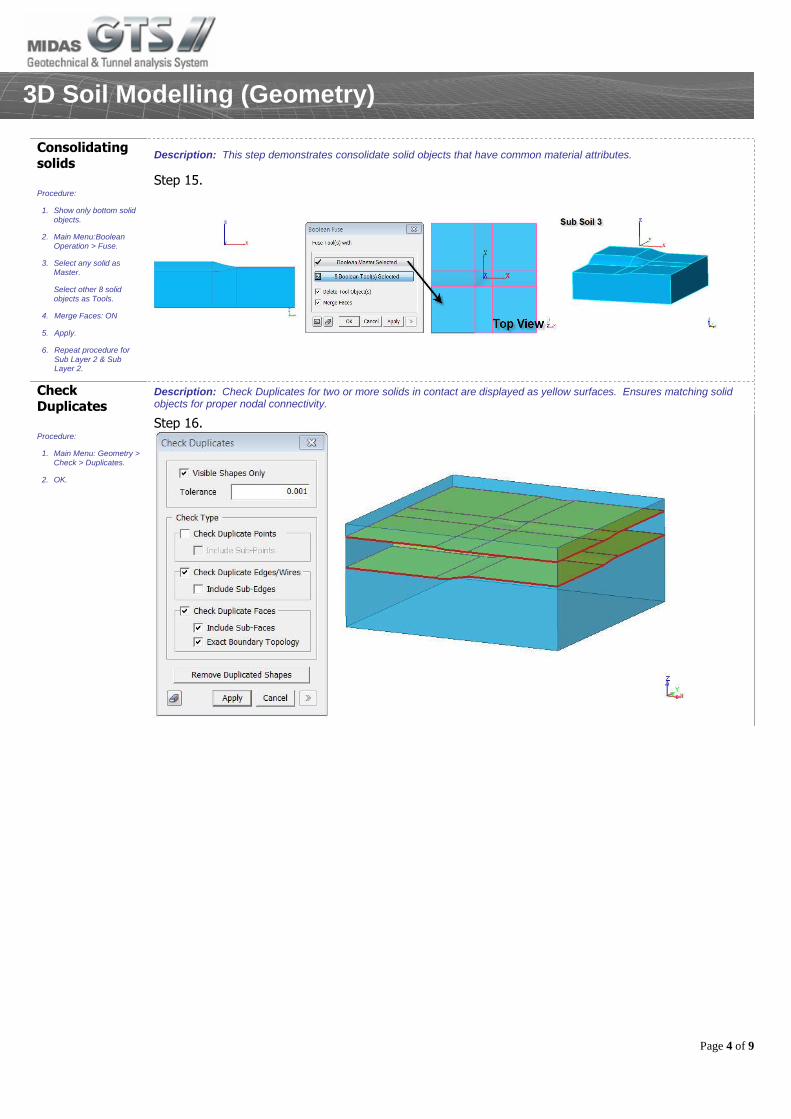
Consolidating solids
Description: This step demonstrates consolidate solid objects that have common material attributes.
Procedure:
1. Show only bottom solid objects.
2. Main Menu:Boolean Operation > Fuse.
3. Select any solid as Master.
Select other 8 solid objects as Tools.
4. Merge Faces: ON
5. Apply.
6. Repeat procedure for Sub Layer 2 & Sub Layer 2.
Step 15.
Check Duplicates
Description: Check Duplicates for two or more solids in contact are displayed as yellow surfaces. Ensures matching solid objects for proper nodal connectivity.
Procedure:
1. Main Menu: Geometry > Check > Duplicates.
2. OK.
Step 16.
Page 5 of 9
3D Modelling of Pile Mat Foundation (Geometry)
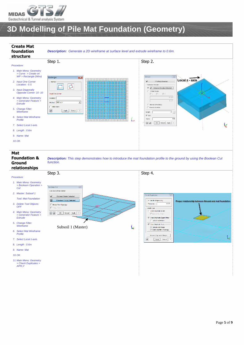
Create Mat
foundation structure
Description: Generate a 2D wireframe at surface level and extrude wireframe to 0.6m.
Procedure:
1. Main Menu: Geometry > Curve > Create on WP > Rectangle (Wire)
2. Input One Corner Location: -5 5
3. Input Diagonally Opposite Corner: 10 -10
4. Main Menu: Geometry > Generator Feature > Extrude
5. Change Filter: Wireframe
6. Select Mat Wireframe Profile
7. Select Local z-axis.
8. Length : 0.6m
9. Name: Mat
10. OK.
Step 1.
Step 2.
Mat Foundation &
Ground relationships
Description: This step demonstrates how to introduce the mat foundation profile to the ground by using the Boolean Cut function.
Procedure:
1. Main Menu: Geometry > Boolearn Operation > Cut
2. Master: Subsoil 1
Tool: Mat Foundation
3. Delete Tool Objects: OFF
4. Main Menu: Geometry > Generator Feature > Extrude
5. Change Filter: Wireframe
6. Select Mat Wireframe Profile
7. Select Local z-axis.
8. Length : 0.6m
9. Name: Mat
10. OK.
11. Main Menu: Geometry > Check Duplicates > APPLY
Step 3.
Step 4.
Subsoil 1 (Master)
Page 6 of 9
3D Modelling of Pile Mat Foundation (Geometry)
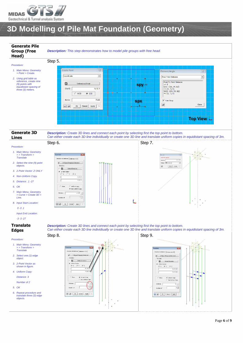
Generate Pile
Group (Free Head)
Description: This step demonstrates how to model pile groups with free head.
Procedure:
1. Main Menu: Geometry > Point > Create.
2. Using grid table as reference, create nine (9) points with equidistant spacing of three (3) meters.
Step 5.
Generate 3D
Lines Description: Create 3D lines and connect each point by selecting first the top point to bottom. Can either create each 3D line individiually or create one 3D line and translate uniform copies in equidistant spacing of 3m.
Procedure:
1. Main Menu: Geometry > > Transform > Translate
2. Select the nine (9) point objects.
3. 2-Point Vector: Z ONLY
4. Non-Uniform Copy.
5. Distance: .1 -27
6. OK
7. Main Menu: Geometry > Curve > Create 3D > Line.
8. Input Start Location:
0 -3 .1
Input End Location:
-3 -3 -27
Step 6.
Step 7.
Translate
Edges Description: Create 3D lines and connect each point by selecting first the top point to bottom. Can either create each 3D line individiually or create one 3D line and translate uniform copies in equidistant spacing of 3m.
Procedure:
1. Main Menu: Geometry > > Transform > Translate
2. Select one (1) edge object.
3. 2-Point Vector as shown in figure.
4. Uniform Copy:
Distance: 3
Number of 2
5. OK
6. Repeat procedure and translate three (3) edge objects.
Step 8.
Step 9.
Page 7 of 9
Mesh Generation of Solids & 3D Pile elements
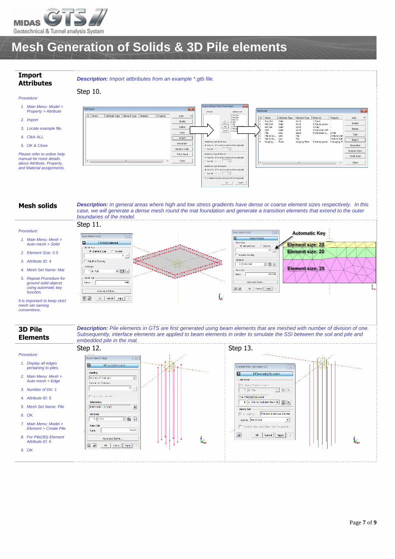
Import
Attributes Description: Import attbributes from an example *.gtb file.
Procedure:
1. Main Menu: Model > Property > Attribute
2. Import
3. Locate example file.
4. Click ALL
5. OK & Close
Please refer to online help manual for more details about Attribute, Property, and Material assignments.
Step 10.
Mesh solids Description: In general areas where high and low stress gradients have dense or coarse element sizes respectively. In this case, we will generate a dense mesh round the mat foundation and generate a transition elements that extend to the outer boundaries of the model.
Procedure:
1. Main Menu: Mesh > Auto-mesh > Solid
2. Element Size: 0.5
3. Attribute ID: 4
4. Mesh Set Name: Mat
5. Repeat Procedure for ground solid objects using automatic key function.
It is important to keep strict mesh set naming conventions.
Step 11.
3D Pile Elements
Description: Pile elements in GTS are first generated using beam elements that are meshed with number of division of one. Subsequently, interface elements are applied to beam elements in order to simulate the SSI between the soil and pile and embedded pile in the mat.
Procedure:
1. Display all edges pertaining to piles.
2. Main Menu: Mesh > Auto-mesh > Edge
3. Number of Div: 1
4. Attribute ID: 5
5. Mesh Set Name: Pile
6. OK.
7. Main Menu: Model > Element > Create Pile
8. For Pile(3D) Element Attribute ID: 6
9. OK.
Step 12.
Step 13.
Page 8 of 9
Analysis: Boundary Conditions & Self-weight
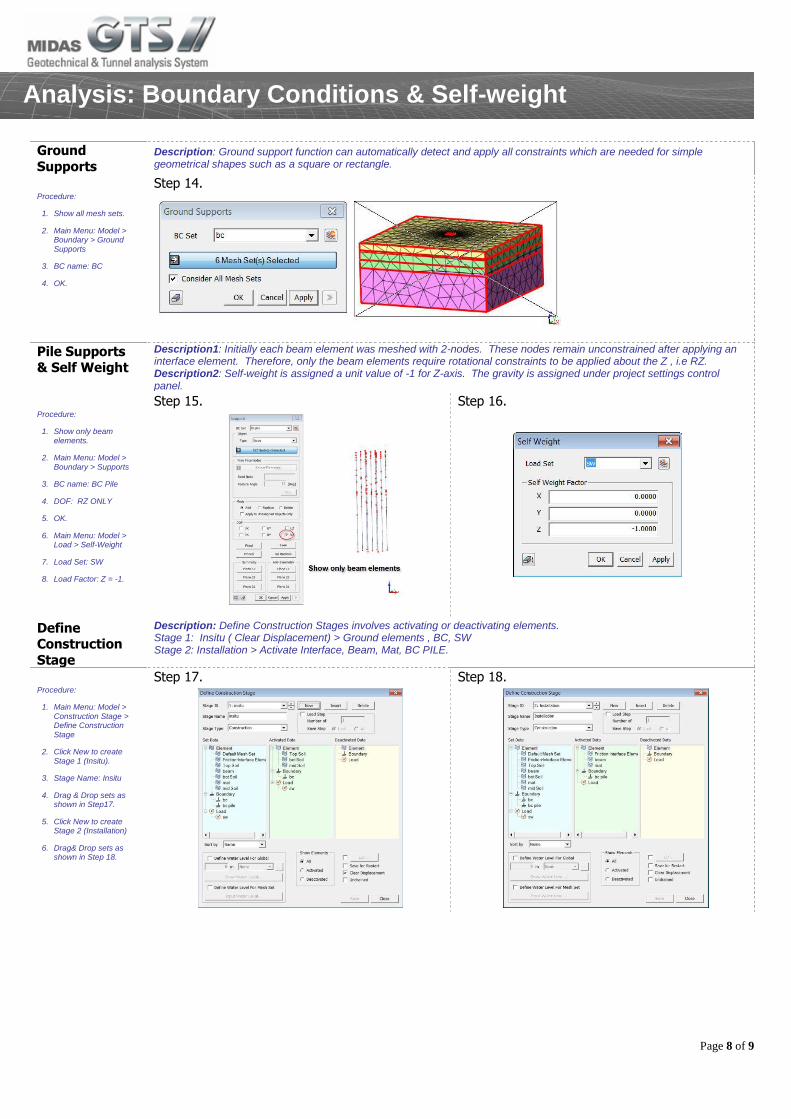
Ground
Supports Description: Ground support function can automatically detect and apply all constraints which are needed for simple geometrical shapes such as a square or rectangle.
Procedure:
1. Show all mesh sets.
2. Main Menu: Model > Boundary > Ground Supports
3. BC name: BC
4. OK.
Step 14.
Pile Supports & Self Weight
Description1: Initially each beam element was meshed with 2-nodes. These nodes remain unconstrained after applying an interface element. Therefore, only the beam elements require rotational constraints to be applied about the Z , i.e RZ. Description2: Self-weight is assigned a unit value of -1 for Z-axis. The gravity is assigned under project settings control panel.
Procedure:
1. Show only beam elements.
2. Main Menu: Model > Boundary > Supports
3. BC name: BC Pile
4. DOF: RZ ONLY
5. OK.
6. Main Menu: Model > Load > Self-Weight
7. Load Set: SW
8. Load Factor: Z = -1.
Step 15.
Step 16.
Define Construction
Stage
Description: Define Construction Stages involves activating or deactivating elements. Stage 1: Insitu ( Clear Displacement) > Ground elements , BC, SW Stage 2: Installation > Activate Interface, Beam, Mat, BC PILE.
Procedure:
1. Main Menu: Model > Construction Stage > Define Construction Stage
2. Click New to create Stage 1 (Insitu).
3. Stage Name: Insitu
4. Drag & Drop sets as shown in Step17.
5. Click New to create Stage 2 (Installation)
6. Drag& Drop sets as shown in Step 18.
Step 17.
Step 18.
Page 9 of 9
Analysis: Boundary Conditions & Self-weight
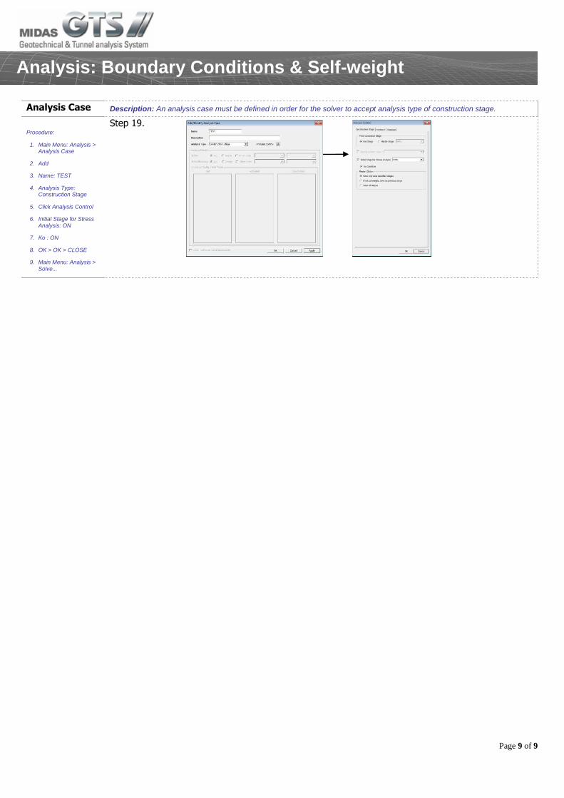
Analysis Case Description: An analysis case must be defined in order for the solver to accept analysis type of construction stage.
Procedure:
1. Main Menu: Analysis > Analysis Case
2. Add
3. Name: TEST
4. Analysis Type: Construction Stage
5. Click Analysis Control
6. Initial Stage for Stress Analysis: ON
7. Ko : ON
8. OK > OK > CLOSE
9. Main Menu: Analysis > Solve...
Step 19.