3dmc machine control - · pdf fileuse of lss combined with the topcon machine control using...
TRANSCRIPT

Interface with
3DMC Machine Control

LSS with Topcon Machine Control Version LSSv10.00.01 Page 2 Mar 2017
© McCarthy Taylor Systems Ltd, 2017
Preamble
In our experience software options are often only used in their simplest forms particularly when
combined with data transfer. This document aims to uncover the more powerful aspects of the
use of LSS combined with the Topcon machine control using 3DMC.
This document assumes the use of LSSv10.00.01 or later and the information is based on default
installation/configuration settings and shows the principles and intricacies of the system from any
perspective or knowledge base.
We hope that this document meets all your expectations, but if you feel that it has fallen short in
any way please let us know so that we may improve its structure and content.
Richard Dalton MRICS Survey Software Specialist McCarthy Taylor Systems Ltd

LSS with Topcon Machine Control Version LSSv10.00.01 Page 3 Mar 2017
© McCarthy Taylor Systems Ltd, 2017
Introduction to Topcon machine control The four data types handled by the machine control are;
1. DTM - also known as the TIN within Topcon.
2. Linework – Comprising both Links and Text - the text informs the operator of names of
surfaces etc
3. Alignments
4. Control
5. Points – these do not yet have a use.
The following relate to the options used to export the above data types and the required steps to
transfer the data through 3D Office and into 3DMC.

LSS with Topcon Machine Control Version LSSv10.00.01 Page 4 Mar 2017
© McCarthy Taylor Systems Ltd, 2017
DTM and Linework - Export to Onboard Instrument DTM
This option exports the LSS model as proprietary Topcon TN3 and LN3 files which are the native
file formats for ‘3D Office’ or ‘3DMC’.
Select ‘Topcon Surfaces (TINs) TN3/LN3’
The triangles can be exported to the TN3 as
either Entire survey or an individual Surface
feature.
‘Adjust levels for surface height / depth’ -
will be available when heighted surface codes
are present in the model and is best used
with a single heighted surface only where
the base / top of the triangles are exported
based on their height / depth values.
Note: for multiple surface heights/depths
within a model please refer to the "Creating a
Formation model" section below to see how an
LSS formation model can be created avoiding
the vertical sides that normally form between
adjacent surfaces of varying depths.
'Linework' and 'General text' are the options, for the LN3 file and are on by default
Please also refer to the Tutorials for both Output options which can be found on the LSS media
or ‘www.dtmsoftware.com/tutorials’

LSS with Topcon Machine Control Version LSSv10.00.01 Page 5 Mar 2017
© McCarthy Taylor Systems Ltd, 2017
3D Office
For a New project select ‘File / New’
‘TIN / Options’ – set Show Boundaries in the Plan view tab
Import data
‘TIN / Import TIN / From 3D TIN file (*.TN3) – this will import the DTM into a new surface in 3D
Office.

LSS with Topcon Machine Control Version LSSv10.00.01 Page 6 Mar 2017
© McCarthy Taylor Systems Ltd, 2017
Points – Export/XYZ (.CSV)
1. From the main menu, select
‘Export/XYZ(.CSV)’.
2. Enter a filename (CSV) and select the dialog
options as shown with the ‘order’ sequential.
3. Select the observations using the selection filter
3D Office
To add the Points data to the model
Points / Import points – from text file (CSV)
Here we need to set up a format of the conversion to match the exported data i.e. Point name /
Easting / Northing / Elevation / Description.
Export data to machine control as PT3
Points / Export selected points – to 3D point file (*.PT3)
Points – Export/LandXML - Observations
4. From the main menu, select ‘Export / LandXML’
5. Enter a filename and select the required options
6. Choose Entire Survey or select the observations
using the selection filter dialog shown opposite

LSS with Topcon Machine Control Version LSSv10.00.01 Page 7 Mar 2017
© McCarthy Taylor Systems Ltd, 2017
Control - Export/Upload Stations
7. From the main menu, select ‘Export/Upload
data to survey instruments’.
8. Select an existing configured logger set to
‘Topcon – GTS7’ (or configure a new one)
and provide a file name for the exported
data.
9. Select Stations - which has no other
options.
3D Office To add the Stations to the model
Project / Import control points – from text file
Here use the same format as used previously with points (i.e. Point name / Easting / Northing /
Elevation / Description)
Export data
Project / Export control points – to 3D control file (*.GC3)
3DMC
All the above files need to be copied to the data card for input to 3DMC
The TIN is used in 3DMC as the Working model.
If the TIN file has surface depths then the original design DTM could also be exported and used
as the Reference model.

LSS with Topcon Machine Control Version LSSv10.00.01 Page 8 Mar 2017
© McCarthy Taylor Systems Ltd, 2017
Creating a Formation Model
This topic describes the combined use of Output / Surface Boundaries and Output /
Survey to build a ‘formation model’ i.e. one that decribes the shape along the top or
underside of each surface feature height/depths of the current model.
The resultant formation model includes a user defined step between adjacent surface
features of different height/depths which avoids anomalies (vertical sides) in the DTM
and can therefore be used for machine control work and setting-out etc.
The following steps are needed to complete the process
1) Use File / SaveAs to create a copy of your current model
2) Repeat the use of Output / Surface Boundaries twice
a. On the first pass use a zero Internal offset distance to tidy the model i.e.
this will make sure that all surface boundaries are linked i.e. are
breaklines in the DTM (this load file can also be used to supply Hatching
boundaries for Autocad)
b. On the second pass use a small Internal offset distance e.g. 10mm, to
create parallel offsets to all the selected boundary lines. This is what the
Output / Survey option uses to avoid the vertical steps in the resultant
formation model where the adjacent surface height/depths have different
values.
3) Finally use the Output / Survey command as described below. See particularly
the option ‘Adjust levels for surface height/depth’ and the related setting
‘Perpendicular to surface’
The rest of this topic describes this process in detail.

LSS with Topcon Machine Control Version LSSv10.00.01 Page 9 Mar 2017
© McCarthy Taylor Systems Ltd, 2017
Output Surface Boundaries
This command creates parallel offsets to the selected surface feature boundaries.
It generates a series of links either on or just inside the outer edge of each nominated surface
feature. These points can be given a level at either a horizontal offset or interpolated from the
Terrain i.e. they are NOT assigned the surface feature height/depth at this point. The
height/depth is only applied to the surface at the Output / Survey stage.
Create file - The name of the load file to create. Selecting "Next" will generate the next available
number to load into the current survey. The file produced may be used to create a separate
survey by specifying an alternative name. By specifying a "+" or a "-" symbol after the load file
number e.g. 200- it is possible to force LSS to generate the next available load file equal to or
below (-) or above (+) this number. For example the user may want to create load files in a
number range. e.g. 001-050 for survey data and 100-200 for design data etc.
Output
Surface feature(s) - The name of the surface feature code(s) to output the boundaries of.
The feature code can be selected or located.
Internal offset distance - The offset distance from the boundary of each Surface code.
Offset link feature - The link feature to apply to the offset points. The feature may be
selected or located.
o Replace existing links - This option will replace any existing links along the offset line if
the offset has been set to zero.
o Calculate terrain level at offset - This option will calculate the level for the new
boundary points by interpolating from the Terrain.

LSS with Topcon Machine Control Version LSSv10.00.01 Page 10 Mar 2017
© McCarthy Taylor Systems Ltd, 2017
Notes
1. Ignored triangles.
LSS will initially check the
survey to see if there are any
thin triangles on the
boundaries of the surface
codes. The tolerance for a thin
triangle is 2x offset value. If a
triangle is found to be
"thinner" than this, then LSS
will ignore it.
If LSS were to include this type of triangle, then seemingly rogue points could be generated.
This test is not carried out when the offset value is zero.
2. Mitred external corners.
LSS will always mitre around the
boundaries...
... except when the external angle is
greater than 275 degrees. In which
case 3 radius points will be created.
3. At the end of the output, LSS will generate a report window if...
a) A number of surface boundaries do not have links.
b) A number of thin triangles have been ignored when generating the surface boundaries.
c) A number of points have landed in a surface feature other than that of the surface boundary being output.
LSS with Topcon Machine Control Version LSSv10.00.01 Page 11 Mar 2017
© McCarthy Taylor Systems Ltd, 2017
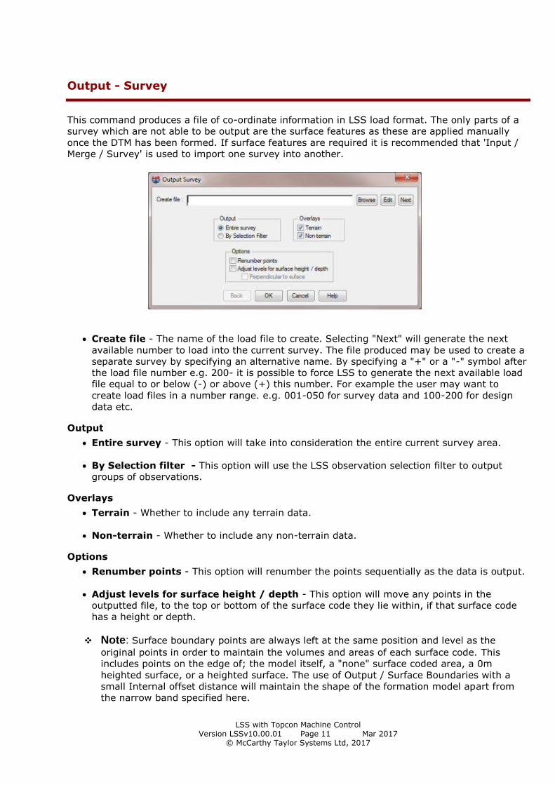
Output - Survey
This command produces a file of co-ordinate information in LSS load format. The only parts of a
survey which are not able to be output are the surface features as these are applied manually
once the DTM has been formed. If surface features are required it is recommended that 'Input /
Merge / Survey' is used to import one survey into another.
Create file - The name of the load file to create. Selecting "Next" will generate the next
available number to load into the current survey. The file produced may be used to create a
separate survey by specifying an alternative name. By specifying a "+" or a "-" symbol after
the load file number e.g. 200- it is possible to force LSS to generate the next available load
file equal to or below (-) or above (+) this number. For example the user may want to
create load files in a number range. e.g. 001-050 for survey data and 100-200 for design
data etc.
Output
Entire survey - This option will take into consideration the entire current survey area.
By Selection filter - This option will use the LSS observation selection filter to output
groups of observations.
Overlays
Terrain - Whether to include any terrain data.
Non-terrain - Whether to include any non-terrain data.
Options
Renumber points - This option will renumber the points sequentially as the data is output.
Adjust levels for surface height / depth - This option will move any points in the
outputted file, to the top or bottom of the surface code they lie within, if that surface code
has a height or depth.
Note: Surface boundary points are always left at the same position and level as the
original points in order to maintain the volumes and areas of each surface code. This
includes points on the edge of; the model itself, a "none" surface coded area, a 0m
heighted surface, or a heighted surface. The use of Output / Surface Boundaries with a
small Internal offset distance will maintain the shape of the formation model apart from
the narrow band specified here.
LSS with Topcon Machine Control Version LSSv10.00.01 Page 12 Mar 2017
© McCarthy Taylor Systems Ltd, 2017
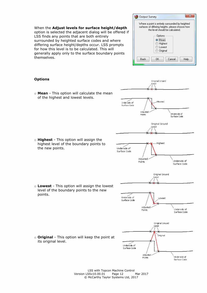
When the Adjust levels for surface height/depth
option is selected the adjacent dialog will be offered if
LSS finds any points that are both entirely
surrounded by heighted surface codes and where
differing surface height/depths occur. LSS prompts
for how this level is to be calculated. This will
generally apply only to the surface boundary points
themselves.
Options
o Mean - This option will calculate the mean
of the highest and lowest levels.
o Highest - This option will assign the
highest level of the boundary points to
the new points.
o Lowest - This option will assign the lowest
level of the boundary points to the new
points.
o Original - This option will keep the point at
its original level.

LSS with Topcon Machine Control Version LSSv10.00.01 Page 13 Mar 2017
© McCarthy Taylor Systems Ltd, 2017
Perpendicular to surface - This option will move any points in the outputted file, to be
perpendicular to the relevant surface.
When dealing with relatively horizontal surfaces the difference between a vertical depth and
one which is measured perpendicular to the slope will be negligible. However, the steeper
the slope, the greater will be the discrepancy and it is because of this fact that this
additional option has been offered.
Here are a few rules:-
1) Observations within surfaces will be offset perpendicular to the slope
2) Any points on the edge of the survey, or a "none" area, or a 0m heighted surface is
always at the same position and level as original, to maintain volumes in adjacent surfaces.
3) Any points on a surface boundary, but surrounded by surface depths, are extended
vertically, and all surrounding triangles are offset, then the mean level of intersections with
this line is calculated
4) (i) If all surrounding triangles to the point intersect the line from original to new at more
than 0.1m apart (the mean is taken), then a PIN1 feature is created.
(ii) If the new point is further away in plan than twice the surface height, then a PIN2
feature code is created.

LSS with Topcon Machine Control Version LSSv10.00.01 Page 14 Mar 2017
© McCarthy Taylor Systems Ltd, 2017
(1) This line is vertical
because it is on a surface
boundary. This is to
maintain the plan areas.
(2) The offset triangles (by
surface height/depth) in
this case are calculated to
intersect with the vertical
line (Normally the new
point is calculated to where
the offset triangles
intersect).
(3) The Mean / Highest /
Lowest is then taken.
Quality Assurance
When the data is outputted, some points may include a point feature such as PIN1, PIN2 or PIN3.
1. PIN1 – The new point is calculated based on the surrounding triangles. LSS will check
between the original point to the new one and then if any surrounding triangles cross this
line. A PIN1 feature is generated if any of these intersections are 0.1m away from the new
point coordinates. The new point is not adjusted.
2. PIN2 - where the new point is further away in plan than twice the surface height.
3. PIN3 - where the point ends up in a different surface and is made vertical to original.
