3e technologies international, inc. (3eti) · 2016-12-15 · that allows for full-duplex mesh links...
TRANSCRIPT

3e Technologies International, Inc. (3eTI)
WWWhhhiiittteee PPPaaapppeeerrr
Mesh Networking Architectures and System Topologies
1 Confidential 3eTI 2005
3e Technologies International, Inc. (3eTI)
Table of Contents 1. Introduction......................................................................................................................... 3 2. System Capabilities............................................................................................................. 3
2.1 Utilization of 3eTI’s Mesh network capable dual radio AP-Bridge nodes..................... 3 2.2 Advantages of a multi-radio solution.............................................................................. 4
3. Network Configuration Models .......................................................................................... 6 3.1 Hotspot Service Provider Configuration......................................................................... 6 3.2 WISP Configuration........................................................................................................ 7
4. Summary ............................................................................................................................. 8
Appendix A: Dual Bridge throughput test report Appendix B: Hardware encryption throughput test report Appendix C: Tsinghua University competitive Mesh Throughput test results compared to 3eTI
internal tests
2 Confidential 3eTI 2005
3e Technologies International, Inc. (3eTI)
1. Introduction Mesh networking techniques have gained significant attention for a variety of applications. Mesh algorithms have the potential to greatly expand the flexibility, deploy-ability, and scalability of WiFi systems. It has therefore gained substantial interest from Municipalities, service providers, and industrial customers interested in extending the wired infrastructure into un-served areas. However, each type of deployment will face differing bandwidth utilization demands from the applications using the Mesh infrastructure bandwidth and will have differing reliability expectations.
Applications as voice and video will require high quality of service and therefore place a premium on minimizing system latency. In addition, video will demand high bandwidth availability. Industrial users may not need very high bandwidth, but latency and system uptime will be critical for customers to develop confidence in the network. Finally, if the goal is to extend the Mesh network over a large area where fixed WAN backhaul is limited, then the ability to maintain high bandwidth links is a critical success factor.
Each customer must examine their needs and determine the systems capabilities of the various architectures that fits their needs.
2. System Capabilities
2.1 Utilization of 3eTI’s Mesh network capable dual radio AP-Bridge nodes 3eTI’s mesh enabled access points are designed for maximum performance and ease of installation for wireless broadband coverage. The 3e-525C-3 is a ruggedized access point / bridge intended for use in outdoor environments where extreme weather conditions are encountered. Incorporating an IP67 weather rated enclosure, derived from military design, it can operate from -30º to 70º C if equipped with the optional temperature control module. It accommodates user selectable 802.11a, 802.11b/g or high speed turbo a, and super g modes to provide maximum bandwidth to the user. The units allow combined local area access with integrated backhaul. The user can select how to deploy each unit, there are 2 radios available to be used in whichever mode the user chooses, based on the specific needs of the network topology. For maximum backhaul bandwidth, 1 node per service installation may be set up as a dual bridge (see example 4 “Infrastructure Mesh” under section 2.2). 3eTI has tested its systems using the various modes available and found them to provide class leading latency and throughput over a large scale Mesh network. Results of internal tests for throughput and latency over multiple hops through Mesh network nodes is shown in Appendix A at the end of this paper. The superior results are achieved using a version of spanning tree protocol, whereby the topology of accessible nodes across the network are mapped into the memory of each node, and an optimal route selected using an algorithm that selects links based on signal strength, throughput, and latency. After the optimal route is selected, others are “pruned” until there is a
3 Confidential 3eTI 2005

3e Technologies International, Inc. (3eTI)
disruption. At that point, the new best route is recalculated and the backhaul path reestablished. This process gives the Mesh network its self configuring and self healing capabilities. Combining the Mesh algorithms with a multi-radio hardware platform allows the system to maximize the capabilities of the algorithms to deliver a high availability and high capacity network.
2.2 Advantages of a multi-radio solution Any single radio solution must share its channel among several services and devices competing for the available bandwidth. Since the 802.11 carrier sensing multiple access (CSMA/CA) protocols require each device to issue a request to send (RTS) followed by a clear to send (CTS) signal, the latency for any given communication session will be highly variable, depending on the demand on a given node at any point in time. Therefore, the single radio system will have high average and highly variable latency. Further, with each backhaul link operating half-duplex (that is, the uplink and downlink message occurs at different times), the available bandwidth drops by more than half for each hop away from the satellite WAN uplink.
Advantages1. Ad-hoc - 1 radio half duplex
– Low cost
Disdvantages
– Low Bandwidth and high latency due to shared multi-mode single radio
– Backhaul loss over 50% per hop
– Total bandwidth available is divided by number of shared connections, including clients and backhaul bridges~15Mbps,
latency highly variable
~7Mbps
~15Mbps, latency highly variable
Moving to a 2 radio system, such as the 3e-525C-2 or 3e-525C-3 gives latency predictability, with about 1ms per hop tested for 3eTI’s systems, vs. 30ms min and 100ms max needed to support time sensitive applications such as voice. There are, however, throughput concerns if the network size is large since a single radio is used for mesh backhaul and is, as in the previous scenario, operating in half-duplex mode.
4 Confidential 3eTI 2005
3e Technologies International, Inc. (3eTI)
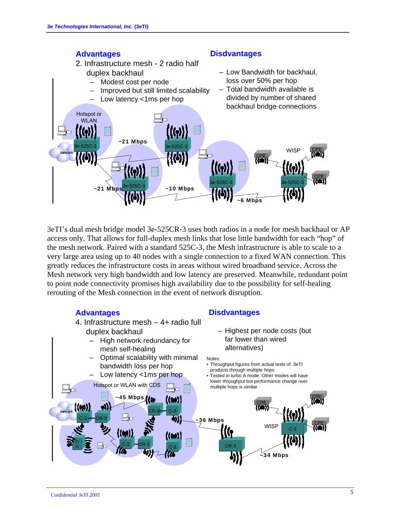
Advantages2. Infrastructure mesh - 2 radio half
duplex backhaul– Modest cost per node– Improved but still limited scalability– Low latency <1ms per hop
Disdvantages
– Low Bandwidth for backhaul, loss over 50% per hop
– Total bandwidth available is divided by number of shared backhaul bridge connections
~21 Mbps3e-525C-33e-525C-3
3e-525C-33e-525C-3
3e-525C-33e-525C-3
3e-525C-33e-525C-3~21 Mbps ~10 Mbps
~6 Mbps
3e-525C-33e-525C-3
CPECPECPECPE
CPECPE
Hotspot or WLAN
WISP
3eTI’s dual mesh bridge model 3e-525CR-3 uses both radios in a node for mesh backhaul or AP access only. That allows for full-duplex mesh links that lose little bandwidth for each “hop” of the mesh network. Paired with a standard 525C-3, the Mesh infrastructure is able to scale to a very large area using up to 40 nodes with a single connection to a fixed WAN connection. This greatly reduces the infrastructure costs in areas without wired broadband service. Across the Mesh network very high bandwidth and low latency are preserved. Meanwhile, redundant point to point node connectivity promises high availability due to the possibility for self-healing rerouting of the Mesh connection in the event of network disruption.
C-3C-3
Disdvantages
– Highest per node costs (but far lower than wired alternatives)
~24Mbps
C-3C-3
~34 Mbps
~45 MbpsCPECPE
CPECPE
CPECPE~36 Mbps
Hotspot or WLAN with CDS
WISP
CR-3CR-3 C-3C-3
CR-3CR-3
Advantages4. Infrastructure mesh – 4+ radio full
duplex backhaul– High network redundancy for
mesh self-healing– Optimal scalability with minimal
bandwidth loss per hop– Low latency <1ms per hop
C-3C-3
CR-3CR-3C-3C-3
CR-3CR-3
C-3
C-3
Notes:• Throughput figures from actual tests of 3eTI
products through multiple hops• Tested in turbo A mode. Other modes will have
lower throughput but performance change over multiple hops is similar
5 Confidential 3eTI 2005

3e Technologies International, Inc. (3eTI)
In the above example, directional antennas are suggested to minimize channel interference in dense areas, such as the Hotspot service, or to bridge long distances such as for the WISP service. Choice of antenna is left to the installer to determine depending on the specific needs of a particular installation. A site survey is advisable to determine the optimal equipment setup topology and configuration. Results of 3eTI mesh network throughput tests using dual-bridge full-duplex nodes are included in the attached appendix A.
3. Network Configuration Models There are 2 possible configurations for remote areas:
1. Hotspot service provider – uses network of overlapping access points linked with mesh bridges to provided ubiquitous hotspot coverage for any authorized customer’s client devices
2. Wireless service provider (WISP) – uses customer premises equipment (CPE) device to extend node range and guarantee local network connectivity
In the diagrams below, a Satcom uplink is shown for the WAN connection needed to support the remote Mesh network, but any fixed (DSL, T1, fiber, etc) or high bandwidth wireless (such as WiMax or microwave) connection could be used. Mixed mode configurations are also possible, depending on the particular requirements of specific implementations.
3.1 Hotspot Service Provider Configuration
Mesh nodes are will typically overlap to provide a continuous service area using wireless distribution system (WDS). Both APs and bridge radios could operate with omni-directional
6 Confidential 3eTI 2005

3e Technologies International, Inc. (3eTI)
antennas, although directional antennas on the bridging radios will provide some advantages in greater link stability and lower channel conflict since the RF patterns will interfere with each other less. One possibility would be to use directional antennas for multiple primary links (see chart above) and omni-directional antennas where redundant secondary links are present. The service area of the hotspot configuration provides access for common user devices operating in client mode, such as Centrino laptops and WiFi equipped PDAs. The service restricts each session to authorized users only through login permissions, which can vary depending on VLAN configurations of multiple BSSIDs to allow multiple networks to share the same physical infrastructure. However, because the hotspot is operating with omni-directional antennas and needs to receive signals from low powered client devices, the AP density must be much higher than for the WISP configuration. It is best used for dense environments such as urban downtowns, where mobility and pervasive broadband access is the primary consideration. The actual number of mesh nodes needed varies depending on line-of-sight availability and whether clients are indoors or outdoors. With line-of-sight, up to 600m range should be possible. However, it is best to count on no more than 200m range given the uncertainties posed by environmental conditions such as wooded areas, and attenuation from walls and buildings. At least 5 nodes, although possible more, depending on the degree of signal attenuating obstructions in the coverage area, will be needed to cover a 1 sq km area. These nodes would share a single connection to the WAN uplink and backhaul their signal through a mesh network. Some hotspots would use 2 or 3 radios operating in Mesh bridging mode and 1 AP for the hotspot, while others operating on the edge of the CDS coverage area would only need 1 dual radio node. The However, the advantage is elimination of CPEs and SOHO wireless routers, since there will be nearly ubiquitous hotspot coverage in the 1 sq km area. Therefore, about 100-150 mesh AP nodes would be needed for the proposed project, but no CPEs or wireless routers are required, which would result in a net savings.
3.2 WISP Configuration In WISP configuration, fewer APs are needed because the CPE is configured with a high gain directional antenna in a fixed position aimed toward the AP node. The node can be set up in dual AP node with sector antennas to improve range. The combination allows greater range and coverage area and would permit the 10-20 users to share a single node in most cases, unless the coverage area is significantly more than 1 sq km. Each user could be guaranteed a minimum of 128kbps, and usually substantially higher, even if all 20 users are simultaneously accessing the AP, provided the satcom link provides a constant 20mbps. Under those conditions, 20mbps / 20 users or 1mbps would be available per user. The AP is capable of up to 44mbps in turbo A mode, per 3eTI tests. In this configuration, usually 1, and probably no more than 2 AP nodes will be needed to cover a community of 20-30 clients, assuming the CPEs have good line of sight visibility of the node’s antenna. However, 1 CPE per user will be required, for a total of 200-400 CPEs. Furthermore, the users will be restricted by the need to maintain connectivity to the CPE. That could be reduced by connecting low cost SOHO wireless routers to the system, at a modest increase in cost.
7 Confidential 3eTI 2005

3e Technologies International, Inc. (3eTI)
Satellite dish
Satellite
1000m
CPECPECPE
CPE
CPECPE CPE
CPE
CPECPE
1000m
CPECPECPE
CPE
CPECPE CPE
CPE
CPECPE
4. Summary 3eTI has long experience building high capacity wireless infrastructure for the military and government agencies. The Mesh architecture has been tested and proven under the most demanding circumstances, and tested for security flaws using the most rigorous military standards. Unlike many start-ups and recent entrants to the marketplace which are enhancing low performance small office and home systems to more demanding WISP, Industrial, and MetroWiFi environments, 3eTI’s systems have been designed for more demanding applications and are adapted to meet the unique needs of high end commercial markets while retaining their military grade design characteristics. With 3eTI’s wireless for a hostile world, top performance is standard equipment.
8 Confidential 3eTI 2005
3e Technologies International, Inc. (3eTI)
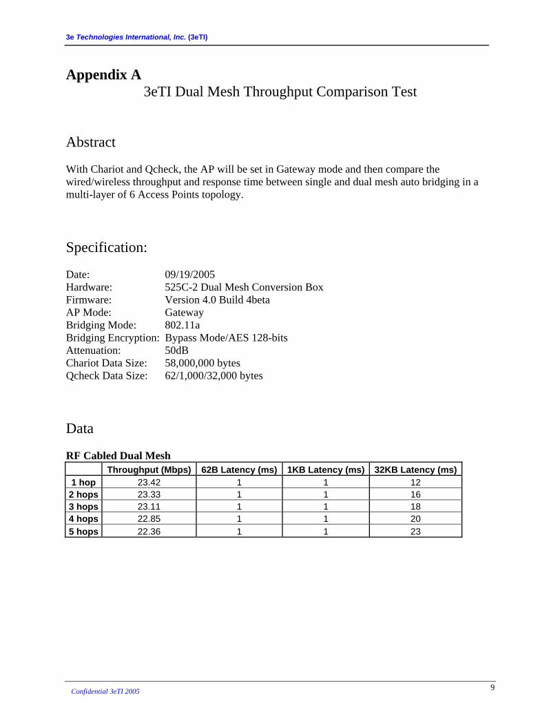
Appendix A 3eTI Dual Mesh Throughput Comparison Test
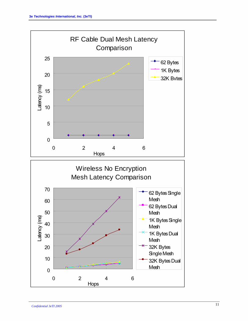
Abstract With Chariot and Qcheck, the AP will be set in Gateway mode and then compare the wired/wireless throughput and response time between single and dual mesh auto bridging in a multi-layer of 6 Access Points topology. Specification: Date: 09/19/2005 Hardware: 525C-2 Dual Mesh Conversion Box Firmware: Version 4.0 Build 4beta AP Mode: Gateway Bridging Mode: 802.11a Bridging Encryption: Bypass Mode/AES 128-bits Attenuation: 50dB Chariot Data Size: 58,000,000 bytes Qcheck Data Size: 62/1,000/32,000 bytes Data RF Cabled Dual Mesh
Throughput (Mbps) 62B Latency (ms) 1KB Latency (ms) 32KB Latency (ms)1 hop 23.42 1 1 12 2 hops 23.33 1 1 16 3 hops 23.11 1 1 18 4 hops 22.85 1 1 20 5 hops 22.36 1 1 23
9 Confidential 3eTI 2005

3e Technologies International, Inc. (3eTI)
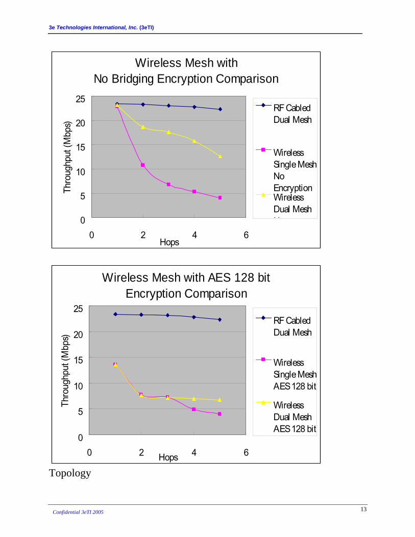
Wireless Mesh with No Bridging Encryption Throughput (Mbps) 62B Latency (ms) 1KB Latency (ms) 32KB Latency (ms) Single Dual Single Dual Single Dual Single Dual
1 hop 22.87 23.24 1 1 1 1 15 13 2 hops 10.84 18.74 2 2 2 2 26 17 3 hops 6.85 17.57 3 3 4 3 39 22 4 hops 5.29 15.8 4 4 5 5 50 29 5 hops 4.03 12.67 5 5 6 5 62 34
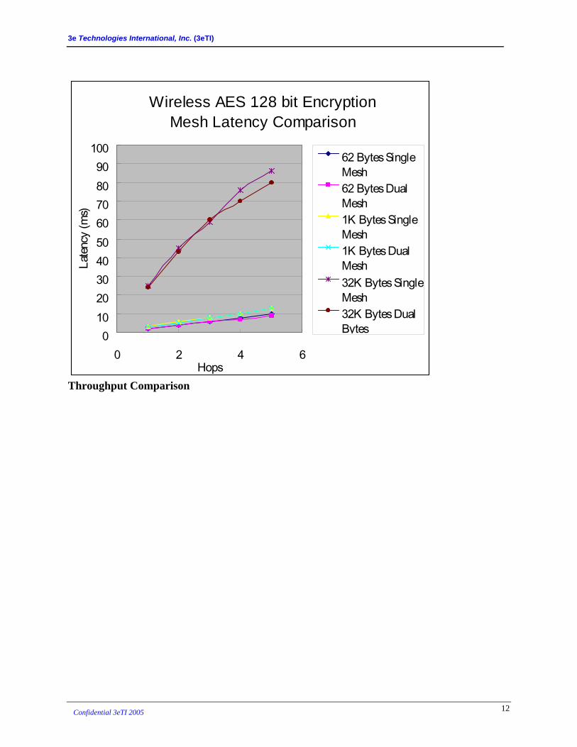
Wireless Mesh with AES 128 bit Bridging Encryption* Throughput (Mbps) 62B Latency (ms) 1KB Latency (ms) 32KB Latency (ms)
Single Dual Single Dual Single Dual Single Dual 1 hop 13.62 13.69 2 2 3 3 25 24 2 hops 7.81 7.66 4 4 6 5 45 43 3 hops 7.29 7.26 6 6 8 8 59 60 4 hops 4.92 7.02 8 7 10 10 76 70 5 hops 3.96 6.82 10 9 13 13 86 80
* Note: See further improved throughput results when 128bit AES-CCM hardware encryption is enabled in Appendix B. According to that test, a 58% throughput improvement can be expected with using hardware encryption in place of software encryption used for the test above.
Comparison Charts Latency Comparison
10 Confidential 3eTI 2005
3e Technologies International, Inc. (3eTI)
RF Cable Dual Mesh LatencyComparison
0
5
10
15
20
25
0 2 4 6Hops
Laten
cy (m
s)
62 Bytes1K Bytes32K Bytes
Wireless No EncryptionMesh Latency Comparison
0
10
20
30
40
50
60
70
0 2 4 6Hops
Laten
cy (m
s)
62 Bytes SingleMesh62 Bytes DualMesh1K Bytes SingleMesh1K Bytes DualMesh32K BytesSingle Mesh32K Bytes DualMesh
11 Confidential 3eTI 2005
3e Technologies International, Inc. (3eTI)
Wireless AES 128 bit EncryptionMesh Latency Comparison
0102030405060708090
100
0 2 4 6Hops
Laten
cy (m
s)
62 Bytes SingleMesh62 Bytes DualMesh1K Bytes SingleMesh1K Bytes DualMesh32K Bytes SingleMesh32K Bytes DualBytes
Throughput Comparison
12 Confidential 3eTI 2005
3e Technologies International, Inc. (3eTI)
Wireless Mesh withNo Bridging Encryption Comparison
0
5
10
15
20
25
0 2 4 6Hops
Thro
ughp
ut (M
bps)
RF CabledDual Mesh
WirelessSingle MeshNoEncryptionWirelessDual MeshN
Wireless Mesh with AES 128 bitEncryption Comparison
0
5
10
15
20
25
0 2 4 6Hops
Thro
ughp
ut (M
bps)
RF CabledDual Mesh
WirelessSingle MeshAES 128 bit
WirelessDual MeshAES 128 bit
Topology
13 Confidential 3eTI 2005
3e Technologies International, Inc. (3eTI)
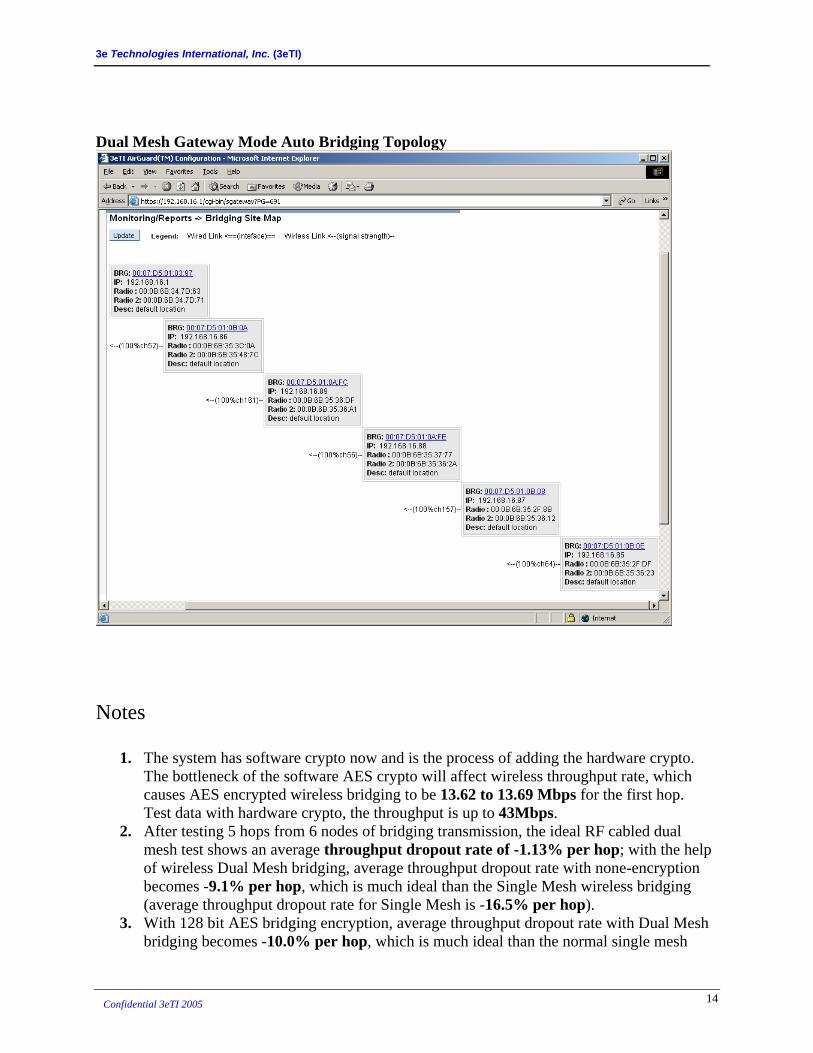
Dual Mesh Gateway Mode Auto Bridging Topology
Notes
1. The system has software crypto now and is the process of adding the hardware crypto. The bottleneck of the software AES crypto will affect wireless throughput rate, which causes AES encrypted wireless bridging to be 13.62 to 13.69 Mbps for the first hop. Test data with hardware crypto, the throughput is up to 43Mbps.
2. After testing 5 hops from 6 nodes of bridging transmission, the ideal RF cabled dual mesh test shows an average throughput dropout rate of -1.13% per hop; with the help of wireless Dual Mesh bridging, average throughput dropout rate with none-encryption becomes -9.1% per hop, which is much ideal than the Single Mesh wireless bridging (average throughput dropout rate for Single Mesh is -16.5% per hop).
3. With 128 bit AES bridging encryption, average throughput dropout rate with Dual Mesh bridging becomes -10.0% per hop, which is much ideal than the normal single mesh
14 Confidential 3eTI 2005
3e Technologies International, Inc. (3eTI)
wireless bridging (average throughput dropout rate of -14.1% per hop). As AES encryption is processed on both bridging radio, Dual Mesh will be around 40~50% more efficient than Single Mesh in throughput dropout rate.
4. In term of latency analysis, it has been stable for smaller data size that each hop will take around 1ms per hop, as long as the testing file packet size is less than 1000 bytes.
5. With file size of 32,000 bytes, AES bridging encrypted latencies seem similar between Single and Dual Mesh that their increasing rates are 68.8 and 66.7% per hop. 82.7 and 52.3 % are the rate for non-encrypted Single and Dual Mesh that they all seems pretty high after comparing to 38% from the idea RF cabled Dual Mesh bridging. This has lots to do with wireless RF interference and testing environment based on the room structure and set-up.
6. Please check the attached files from Chariot and Qcheck for more detailed data and analysis.
15 Confidential 3eTI 2005

3e Technologies International, Inc. (3eTI)
Appendix B Note that the units in the above tests were using AES-CCM software encryption, as is needed to comply with FIPS 140-2 criteria. However, for the 3e-525C-3 and 3e-525CR-3 128bit hardware encryption has been enabled for 802.11i security. Throughput with hardware encryption under different modes tested as follows:
Bridge Encryption Setting Average Throughput (Mbps)
Bridge b/g Mixed with AES-CCM 128-bit 17.779 Bridge Super G with AES-CCM 128-bit encryption 29.188 Bridge 11a with AES-CCM 128-bit encryption 23.488 Bridge Turbo A with AES-CCM 128-bit encryption 44.459
Compare with above tests – 802.11a with 128bit software encryption tested 13.62 Mbps, versus 23.488 Mbps above, a 58% improvement over the software encryption tested in the dual Mesh bridge throughput comparison test of appendix A.
16 Confidential 3eTI 2005

3e Technologies International, Inc. (3eTI)
Appendix C Tsinghua University conducted a Mesh throughput test comparing Tropos MetroMesh and Nortel WMN mesh sThe tests examined the throughput deterioration of the competing over multiple hops for a single client endpoint. They did not explore the latency question as did 3eTI’s tests in Appendix A.
ystems.
Tropos MetroMesh is a single radio system such as described above in section 2.2 in example 1. Mesh bridging and local access share the same 2.4GHz 80211b/g channel. Tropos was set up with a true mesh topology, which allowed the mesh nodes to dynamically choose path to optimize the performance, unlike 3eTI’s test of Appendix A, which linked mesh nodes in a linear topology:
17 Confidential 3eTI 2005

3e Technologies International, Inc. (3eTI)
In contrast, the Nortel systems were placed in a linear topology. Nortel MWM is a 2 channel system such as described in section 2.2 example 2, with 1 radio for local access and a second radio for Mesh bridging.
Test results from Tsinghua for Nortel and Tropos are compared to 3eTI’s results from Appendix A in the chart below
Mesh Throughput Vendor Comparison
0
1
2
3
4
5
6
1 2 3 4 5
Hops Count
Mbp
s
0
5
10
15
20
25
Tropos 802.11b Nortel 802.11b 3eTI single bridge 802.11a 3eTI dual bridge 802.11a
Hatched observations are trendline estimates
18 Confidential 3eTI 2005

3e Technologies International, Inc. (3eTI)
Despite some differences in the testing methodology, the results can be compared to show the relative throughput deterioration across multiple hops. While Tropos received an advantageous setup in the Tsinghua tests, 3eTI compares favorably even for the single bridge mesh test. 3eTI’s single bridge is decisively superior in throughput to Nortel, which was set up in a linear configuration more directly comparable to 3eTI’s internal testing. However, 3eTI’s dual bridge throughput performance is far superior to either competitor’s single bridge systems. Further, Tsinghua did not “stress” the system by connecting a large number of client devices to share the available bandwidth, and did not test for latency. 3eTI believes that such additional tests would have revealed additional advantages for its technology.
19 Confidential 3eTI 2005