3g+c antenna in the galileo monitoring network - fig home page
TRANSCRIPT

TS06B - GNSS Positioning and Measurement II and Remote Sensing - 6688
Dirk Kowalewski
3G+C antenna in the Galileo Monitoring network
FIG Working Week 2013
Environment for Sustainability
Abuja, Nigeria, 6 – 10 May 2013
1/11
3G+C antenna in the Galileo Monitoring network
Dirk KOWALEWSKI, Germany
Key words: GNSS Antennas, Calibration, Monitoring Stations
SUMMARY
The global navigation satellite system Galileo takes big steps to its target. The IOV (In Orbit
Validation) phase is working now. The financing is sure, the satellites are ordered and the
rockets are in mission. In between the control centers, the TTC and the sensor stations are also
building up monitoring stations. This paper informs you about the selection procedure of the
antennas and how important the antenna parameters like multipath reduction and phase center
variation are in the reality.
ZUSAMMENFASSUNG
Das Satellitennavigationssystem Galileo kommt jetzt endlich mit großen Schritten voran. Die
IOV (In Orbit Validation) Phase ist im vollen Gange, die Finanzierung ist gesichert, die
Satelliten sind bestellt und die Raketen sind auch in Auftrag gegeben. Neben den
Kontrollcentern, den TTC und Sensor Stationen werden auch Monitoring Stationen aufgebaut.
Es wird hier auf das Auswahlverfahren und die Wichtigkeit von Antenneneigenschaften wie
gute Multipathunterdrückung und sehr geringe Phasenzentrumsvariationen hingewiesen.

TS06B - GNSS Positioning and Measurement II and Remote Sensing - 6688
Dirk Kowalewski
3G+C antenna in the Galileo Monitoring network
FIG Working Week 2013
Environment for Sustainability
Abuja, Nigeria, 6 – 10 May 2013
2/11
3G+C antenna in the Galileo Monitoring network
Dirk KOWALEWSKI, Germany
1. STATUS OF GALILEO
Galileo, the European Navigation System, has a long history. The first plan of the European
Union was to have an operable system since 2008. The miscarrying of the public private
partnership between the EU and a part of the industrial magnate took a lot of time. The fact
that 27 EU countries discussed about the financing of Galileo didn’t really helped for fast
decisions. But now everything is fixed, the financial budget is concluded and Galileo is on a
good way. The first satellite GIOVE-A started in 2007 and the second test satellite GIOVE-B
followed in 2008. One important payload of GIOVE-B was the hydrogen passive maser clock.
This clock has a significant higher accuracy than the atomic clocks from the GPS or
GLONASS satellite navigation systems. Another big step for Galileo is the signal structure. It
helps to track the signals faster.
1.1 In Orbit Validation (IOV)
The IOV phase is a very important milestone for the Galileo navigation system. In IOV we
have four operable Galileo satellites in the Orbit. Two satellites launched on the 21 October
2011 and the next two on the 12 October 2012. Both Soyuz rockets (Russia) started from the
Guiana Space Centre (CSG) in Kourou in French Guiana. This was the first time that a
Russian missile launched in CSG. Four navigation satellites the absolutely minimum
requirement for a positioning by means of trilateration calculation, as well longitude and
latitude as the altitude and point in time can exactly be captured. Assist by this Satellite
quartet starts the construction of the new worldwide navigation system Galileo. The
development and the manufacturing occur in Ottobrunn, Germany. The main contractor was
EADS Astrium and OHB. The IOV says, that the satellites are fully operable, all
Galileosignals can be received and the monitoring system from two Ground Control Centers
(GCC) works also. One is in Fucino, Italy. They host and operate the Ground Mission
Segment (GMS). Te second one is in Oberpfaffenhofen, Germany. They will host and operate
the Ground Control Segment (GCS). A network of sensor stations is providing the coverage
for orbitography and synchronization of the measurements.
1.2 The next steps of the Galileo navigations system
The EU Commission give the order to OHB Technology to build further 22 Galileo
navigation satellites and EADS Astrium has the order to build also 4 Galileo navigation
satellites. With the 4 IOV satellites the Galileo system will have 30 Satellites in orbit.
Arianespace will send with 6 Sojuz rockets 12 satellites and with three Ariane 5 rockets 12
satellites in the orbit. The target is to have in 2015 a fully operable Galileo navigation system.
In my opinion the chance is very good to have the system in time.

TS06B - GNSS Positioning and Measurement II and Remote Sensing - 6688
Dirk Kowalewski
3G+C antenna in the Galileo Monitoring network
FIG Working Week 2013
Environment for Sustainability
Abuja, Nigeria, 6 – 10 May 2013
3/11
1.3 Technical sheets from the Galileo Satellites
Parameter GIOVE-A GIOVE-B IOV OHC
Launch mass 602 kg 530 kg 700 kg 733 kg
Dry mass 550 kg 502 kg 640 kg 680 kg
Body size 1.3 m x 1.8 m x 1.65 m
0.95 m x 0.95 m x 2.4 m
2.74 m x 1.58 m x 1.59 m
2.5 m x 1.2 m x 1.1 m
Solar array size 2 x 2 x 1.74 m x 0.98 m
2 x 4 x 1.5 m x 0.8 m
2 x 2 x ~3 m x ~1 m
2 x 2 x 2.5 m x 1.1 m
Span width ~10 m ~10 m 14.5 m 14.8 m
Cross section 9 m2 12 m
2 n/a n/a
SRP acceleration 99 nm/s2 151 nm/s
2 113 nm/s
2 n/a
GIOVE-A GIOVE-B Galileo-IOV
2. GALILEO GROUND SEGMENT
The whole Galileo constellation will be monitored from the Galileo ground segment. The task
of the ground segment is to control the Galileo constellation, monitoring satellite health and
uploading data to the satellites. The most important task is the clock synchronization and the
orbit ephemeris. For this job Galileo needs a worldwide network of stations. Forty Galileo
sensor stations (GSS) for orbit determination and time synchronization. Five Galileo TTC
Station with a 13 m antenna dish for telematics and remote control and nine Galileo Mission
Uplink Stations (ULS) to send navigation and integrity signals to the satellites. The following
sheet compares the ground segment infrastructure of GPS and Galileo.
GPS Galileo
Sensor Station 6 40 (GSS)
Uplink Station 3 9 (ULS)
TTC Stations - 5 (TTC)
Control Center 1 2 (GCC)

TS06B - GNSS Positioning and Measurement II and Remote Sensing - 6688
Dirk Kowalewski
3G+C antenna in the Galileo Monitoring network
FIG Working Week 2013
Environment for Sustainability
Abuja, Nigeria, 6 – 10 May 2013
4/11
3. GALILEO MONITORING STATIONS
Further the ESA builds up monitoring stations. The plan is that every country in the EU shall
build up minimum one station. Every monitoring station must have 3 reference stations and
two rovers. The special task is at now not defined, but everybody knows that they have to
control the accuracy and the time shift of the system. For this task they need special GNSS
receivers and also very good GNSS antennas. The following subsection describes the
selection procedure of the GNSS antennas.
4. SELECTION OF GNSS ANTENNAS
In the shortlist came three antennas. The Trimble Zephyr Geodetic II, the Leica AR10 and the
navXperience 3G+C.
4.1 Trimble Zephyr Geodetic II
The brochure of the Trimble Zephyr antenna promises a lot of good parameters, minimum
tracking elevation 0°. But in the leaflet is written in practice more than 3°. An important
feature is the phase center accuracy of 2 mm or better and the phase center repeatability of
less than 1 mm. Furthermore the brochure promises to receive all existing and prospectively
GNSS signals. The Zephyr technology promises a good multipath reduction and the stealth
ground plane cuts reflected signals. The antenna is developed in 2006 and a big quantity of
Zephyr Geodetic II is in the market.
4.2 Leica AR10
The brochure also promises the tracking of all signals from GPS, Glonass Galileo and
Compass (BeiDou), sup-millimeter phase center repeatability and an optimal signal quality. If
you trust the brochure the antenna has nearly a chokering performance and a high multipath
TS06B - GNSS Positioning and Measurement II and Remote Sensing - 6688
Dirk Kowalewski
3G+C antenna in the Galileo Monitoring network
FIG Working Week 2013
Environment for Sustainability
Abuja, Nigeria, 6 – 10 May 2013
5/11
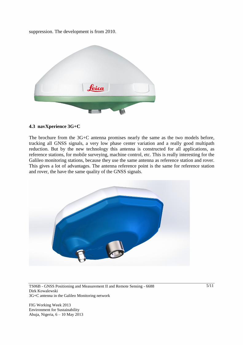
suppression. The development is from 2010.
4.3 navXperience 3G+C
The brochure from the 3G+C antenna promises nearly the same as the two models before,
tracking all GNSS signals, a very low phase center variation and a really good multipath
reduction. But by the new technology this antenna is constructed for all applications, as
reference stations, for mobile surveying, machine control, etc. This is really interesting for the
Galileo monitoring stations, because they use the same antenna as reference station and rover.
This gives a lot of advantages. The antenna reference point is the same for reference station
and rover, the have the same quality of the GNSS signals.

TS06B - GNSS Positioning and Measurement II and Remote Sensing - 6688
Dirk Kowalewski
3G+C antenna in the Galileo Monitoring network
FIG Working Week 2013
Environment for Sustainability
Abuja, Nigeria, 6 – 10 May 2013
6/11
4.4 Compare the technical data
Zephyr Geod. II AR10 3G+C
Tracking all signals Yes Yes Yes
Minimum phase v. Yes Yes Yes
Polarization RHCP RHCP RHCP
Power 3.5 to 20 V 3.3 to 12 V 3.3 to 20 V
Antenna gain 50 dB 29 dB 29 dB the 3G+C
42 dB the 3G+C marine
48 dB the 3G+C reference
Axial Ratio (Zenit) 2 dB 1.4 dB 3 dB
Vibration rating MIL-STD 810f ISO9022-3 MIL-STD 810f
Weight 1.36 kg 1.12 kg 0.38 kg
5. MEASUREMENTS
5.1 Phase Center Variations (PCV)
The phase center of a GNSS antenna is in an ideal case stabile, punctual and constant. It is not
possible to build an antenna without a phase center variation. Each antenna phase center is
flitting according to the azimuth and elevation angle of the satellites. GNSS antennas with
azimuth dependence are not so good antennas. The Trimble and the Leica GNSS antenna
promise a good phase center repeatability, but the brochures doesn’t mention anything about
the phase center variation. The phase center variations are very important for precise
measurements. Nearly each manufacture of GNSS antennas let them calibrate from
independent companies or Institutes. It needs minimum 5 antennas for a typical calibration
file. The following chapters show the results of calibrations. Everybody can download the
typical calibration files from the following website: http://www.ngs.noaa.gov/ANTCAL/.
Here are the results absolute comparable, because all calibration has been done from the same
company, Geo++. They made the typical calibration for these three antennas. Geo++
calibrated five antennas from AR10, six antennas from the Zephyr und eight antennas from
the 3G+C.

TS06B - GNSS Positioning and Measurement II and Remote Sensing - 6688
Dirk Kowalewski
3G+C antenna in the Galileo Monitoring network
FIG Working Week 2013
Environment for Sustainability
Abuja, Nigeria, 6 – 10 May 2013
7/11
5.1.1 Zephyr Geodetic II: results of the typical calibration
GPS L1 GPS L2 GLONASS L1 GLONASS L2
5.1.2 Leica AR10: results of the typical calibration
GPS L1 GPS L2 GLONASS L1 GLONASS L2
5.1.3 navXperience 3G+C: results of the typical calibration
GPS L1 GPS L2 GLONASS L1 GLONASS L2
5.1.4 Assessment of the results
The Trimble Zephyr Geodetic II has a phase center variation from -4 to +8 mm and the
antenna has only the variation in the height. This is a really good result. The Leica AR10 has
a phase center variation of 12 mm, but the wings are not good for the accuracy when you
work without a calibration or if you use this antenna for a mobile (rover) application. This
antenna was canceled for the next step. The navXperience 3G+C has only a maximum of 4
mm phase center variation and also only variations in the height. In this comparison the 3G+C
is better. The next step was to elaborate the navXperience 3G+C antenna for the qualification
TS06B - GNSS Positioning and Measurement II and Remote Sensing - 6688
Dirk Kowalewski
3G+C antenna in the Galileo Monitoring network
FIG Working Week 2013
Environment for Sustainability
Abuja, Nigeria, 6 – 10 May 2013
8/11
as a reference and mobile GNSS antenna.
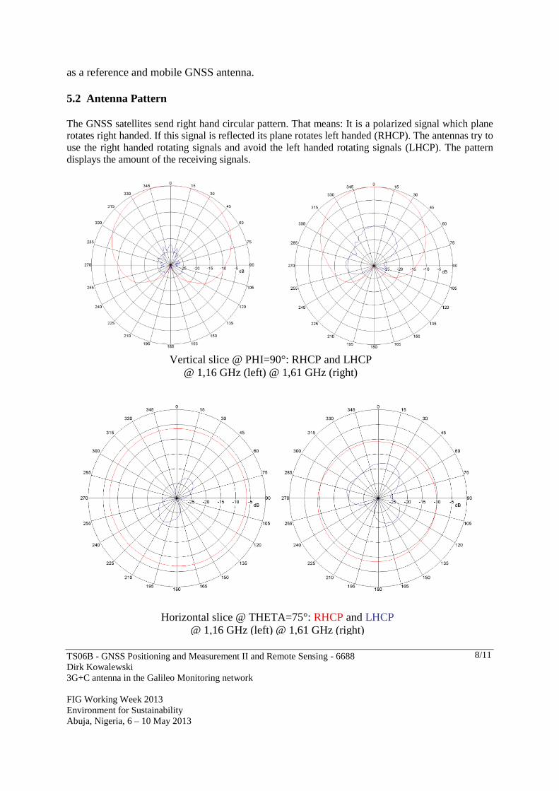
5.2 Antenna Pattern
The GNSS satellites send right hand circular pattern. That means: It is a polarized signal which plane
rotates right handed. If this signal is reflected its plane rotates left handed (RHCP). The antennas try to
use the right handed rotating signals and avoid the left handed rotating signals (LHCP). The pattern
displays the amount of the receiving signals.
Vertical slice @ PHI=90°: RHCP and LHCP
@ 1,16 GHz (left) @ 1,61 GHz (right)
Horizontal slice @ THETA=75°: RHCP and LHCP
@ 1,16 GHz (left) @ 1,61 GHz (right)

TS06B - GNSS Positioning and Measurement II and Remote Sensing - 6688
Dirk Kowalewski
3G+C antenna in the Galileo Monitoring network
FIG Working Week 2013
Environment for Sustainability
Abuja, Nigeria, 6 – 10 May 2013
9/11
The red line shows the received quality of the RHCP signals and the blue line shows the LHCP
signals. The measurement told us that the 3G+C antenna has a very good multipath reduction (blue
line) and enough gain to receive the signals from the satellites with low elevation (0°).
5.3 Filtering
The antenna filter was measured with a network analyzer. The input of the antenna is not
accessible. A wideband log-periodic antenna was used to radiate into the 3G+C. This implies
that the measurements are only relative and of limited accuracy. Nevertheless, we can
conclude the antenna is nicely tuned to all GNSS frequency, with rather good suppression by
50dB typically with the exception of parts of the spectrum around 2.5GHz.
In spite of this filter, really strong signals, such as the air traffic radar at Bertem, which has a
line of sight with the installation on the roof, can still leak through and saturate the amplifier.
The radar in our vicinity has a frequency of 1.274GHz and the first and second harmonic are
clearly leaking through. Following measurements show the peak power recorded with a
spectrum analyzer.

TS06B - GNSS Positioning and Measurement II and Remote Sensing - 6688
Dirk Kowalewski
3G+C antenna in the Galileo Monitoring network
FIG Working Week 2013
Environment for Sustainability
Abuja, Nigeria, 6 – 10 May 2013
10/11
5.4 The passive gain
The value of the passive gain is in dbic. For simplifying you can determine: If the value is
higher the antenna is able to hear better the signals from the satellites. Normally the receiver
hears nothing under a value of 2 dbic. The 3G+C antenna has a really good passive gain. Here
the s/n ratio between 3G+C (blue) and the Zephyr (red).
The 3G+C has e a better s/n ratio with every GPS satellite independent of the elevation angle.
This is the reason to do the next step only with the 3G+C antenna from navXperience.
5.5 The group delay phase variation
The phase delay variation in depend of the elevation angle is very important for the time
synchronization and for the accuracy. In March 2013 the Geo++ Company got the order to
make the measurement with three 3G+C antennas. Unfortunately for this paper the
information about the results comes too late. More information about the group delays in the
presentation. In simulation we expect a group delay phase variation under 1 ns.
6. CONCLUSION
A disappointment in the comparisons was the Leica AR10. The brochure promised a new
good antenna design with a high accuracy. But the ANTEX data showed a four wings result
when the elevation angle goes down. We don’t expect these results from a new precise GNSS
antenna. The Zephyr and the 3G+C antenna deliver here much better results. Surprisingly
were the PCV results from the navXperience 3G+C antenna. Also in the other disciplines
surprised the 3G+C antenna: A very good tracking of GNSS satellites with low elevation,
good filters and perfect multipath reduction. If ESA has no negative surprise with the group
delay phase variation the 3G+C antenna is fixed for rover and for reference station in the
Galileo monitoring network.

TS06B - GNSS Positioning and Measurement II and Remote Sensing - 6688
Dirk Kowalewski
3G+C antenna in the Galileo Monitoring network
FIG Working Week 2013
Environment for Sustainability
Abuja, Nigeria, 6 – 10 May 2013
11/11
REFERENCES
J.-A. Avila-Rodriguez, G. W. Hein, S. Wallner, J.-L. Issler, L. Ries, L. Lestarquit, A. de Latour, J.
Godet, F. Bastide, T. Pratt, and J. Owen, 2007, "The MBOC Modulation: The Final Touch to the
Galileo Frequency and Signal Plan,” in Proceedings of the ION GNSS 2007 Meeting, 25-28
September 2007, Fort Worth, Texas, USA (Institute of Navigation, Alexandria, Virginia), pp. 1515-
1529.
J. Hahn and E. Powers, 2007, “A Report on GPS and Galileo Time Offset Coordination Efforts,” in
Proceedings of TimeNav’07, the 21st European Frequency and Time Forum (EFTF) Joint with 2007
IEEE International Frequency Control Symposium (IEEE-FCS), 29 May-1 June 2007, Geneva,
Switzerland (IEEE Publication CH37839), pp. 440-445.
BIOGRAPHICAL NOTES
1987 – 1991 Technische Fachhochschule Berlin Dipl.-Ing. Geodesy
From 2001 Founder and director of the Geo.IT Systeme GmbH
From 2009 Founder and director of the navXperience GmbH
2009 – 2012 Research projects: MoDeSh with GL and HSVA: Motion and Deformation of Ships
From 2010 Developing precise GNSS antennas
From 2012 Member of the working group AK 3 “Measurement method and Systems” DVW Germany
CONTACTS
Dipl.-Ing. Dirk Kowalewski
navXperience GmbH
Querweg 20
13591 Berlin
GERMANY
Tel. +49 30 375 896 7-0
Fax + 49 30 375 896 7-1
Email: [email protected]
Web site: www.navxperience.com