3gpp ts 23.216 v9.2 - qtc.jp utran (hspa) – sgsn (iu-ps) ... handling of srvcc from 3gpp...
TRANSCRIPT
3GPP TS 23.216 V9.2.0 (2009-12) Technical Specification
3rd Generation Partnership Project;Technical Specification Group Services and System Aspects;
Single Radio Voice Call Continuity (SRVCC);Stage 2
(Release 9)
The present document has been developed within the 3rd Generation Partnership Project (3GPP TM) and may be further elaborated for the purposes of 3GPP. The present document has not been subject to any approval process by the 3GPP Organizational Partners and shall not be implemented. This Specification is provided for future development work within 3GPP only. The Organizational Partners accept no liability for any use of this Specification. Specifications and reports for implementation of the 3GPP TM system should be obtained via the 3GPP Organizational Partners' Publications Offices.
3GPP
3GPP TS 23.216 V9.2.0 (2009-12) 2Release 9
Keywords LTE, UMTS, GSM, Circuit mode, IP, multimedia,
IMS, voice
3GPP
Postal address
3GPP support office address 650 Route des Lucioles - Sophia Antipolis
Valbonne - FRANCE Tel.: +33 4 92 94 42 00 Fax: +33 4 93 65 47 16
Intpp.org
Copyright Notification
No part may be reproduced except as authorized by written permission. The copyright and the foregoing restriction extend to reproduction in all media.
© 2009, 3GPP Organizational Partners (ARIB, ATIS, CCSA, ETSI, TTA, TTC).
All rights reserved.
UMTS™ is a Trade Mark of ETSI registered for the benefit of its members 3GPP™ is a Trade Mark of ETSI registered for the benefit of its Members and of the 3GPP Organizational Partners LTE™ is a Trade Mark of ETSI currently being registered for the benefit of its Members and of the 3GPP Organizational Partners GSM® and the GSM logo are registered and owned by the GSM Association
3GPP
3GPP TS 23.216 V9.2.0 (2009-12) 3Release 9
Contents Foreword ...................................................................................................................................................... 5 1 Scope .................................................................................................................................................. 6 2 References .......................................................................................................................................... 6 3 Definitions and abbreviations .............................................................................................................. 7 3.1 Definitions ................................................................................................................................................... 7 3.3 Abbreviations............................................................................................................................................... 8 4 High level Principles and Concepts ..................................................................................................... 8 4.1 High level Principles ............................................................................................................................... 8 4.1.1 Architectural Principles for 3GPP2 1xCS SRVCC ................................................................................... 8 4.1.2 Architectural Principles for 3GPP UTRAN/GERAN SRVCC .................................................................. 8 4.2 Concepts ...................................................................................................................................................... 9 4.2.1 E-UTRAN and 3GPP2 1xCS SRVCC ..................................................................................................... 9 4.2.2 E-UTRAN and 3GPP UTRAN/GERAN SRVCC .................................................................................... 9 4.2.3 UTRAN (HSPA) to 3GPP UTRAN/GERAN SRVCC ........................................................................... 10 4.2.4 SRVCC for IMS emergency sessions .................................................................................................... 11 4.2.4.1 E-UTRAN/UTRAN (HSPA) to 3GPP UTRAN/GERAN .................................................................. 11 4.2.4.2 E-UTRAN to 3GPP2 1xCS .............................................................................................................. 12 4.2.4.3 SRVCC in Limited Service Mode .................................................................................................... 13 4.2.4.3.1 E-UTRAN/UTRAN (HSPA) to 3GPP UTRAN/GERAN ............................................................ 13 4.2.4.3.2 E-UTRAN to 3GPP2 1xCS ........................................................................................................ 13 5 Architecture model and reference points............................................................................................ 14 5.1 General ...................................................................................................................................................... 14 5.2 Reference architecture ................................................................................................................................ 14 5.2.1 E-UTRAN and 3GPP2 1xCS SRVCC architecture ................................................................................ 14 5.2.2 E-UTRAN and 3GPP UTRAN/GERAN SRVCC architecture................................................................ 14 5.2.3 UTRAN (HSPA) and 3GPP UTRAN/GERAN SRVCC architecture ...................................................... 15 5.3 Functional Entities ..................................................................................................................................... 16 5.3.1 3GPP2 1x CS SRVCC interworking solution function (1xCS IWS) ....................................................... 16 5.3.2 MSC Server enhanced for E-UTRAN/UTRAN (HSPA) and 3GPP UTRAN/GERAN SRVCC ............... 16 5.3.3 MME.................................................................................................................................................... 17 5.3.3.1 Interworking with 3GPP2 1xCS IWS ............................................................................................... 17 5.3.3.2 Interworking with 3GPP MSC Server enhanced for SRVCC ............................................................ 17 5.3.3.2.1 Interworking with 3GPP MSC Server enhanced for SRVCC ....................................................... 17 5.3.3.2.2 PS bearer splitting function ........................................................................................................ 17 5.3.3A SGSN ................................................................................................................................................... 17 5.3.3A.1 Interworking with 3GPP MSC Server enhanced for SRVCC ............................................................ 17 5.3.3A.1.1 Interworking with 3GPP MSC Server enhanced for SRVCC ....................................................... 17 5.3.3A.1.2 PS bearer splitting function ........................................................................................................ 18 5.3.4 UE enhanced for SRVCC ...................................................................................................................... 18 5.3.4.1 Interworking with 3GPP2 1xCS ....................................................................................................... 18 5.3.4.2 Interworking with 3GPP UTRAN/GERAN ...................................................................................... 18 5.3.5 Serving/PDN GW ................................................................................................................................. 18 5.3.6 E-UTRAN ............................................................................................................................................ 18 5.3.6.1 Interworking with 3GPP2 1xCS ....................................................................................................... 18 5.3.6.2 Interworking with 3GPP UTRAN/GERAN ...................................................................................... 18 5.3.6A UTRAN (HSPA) .................................................................................................................................. 19 5.3.7 HSS ...................................................................................................................................................... 19 5.3.7.1 Interworking with 3GPP UTRAN/GERAN ...................................................................................... 19 5.4 Reference points ........................................................................................................................................ 19 5.4.1 MME – 3GPP2 1xCS IWS (S102)......................................................................................................... 19 5.4.2 MME/SGSN – MSC Server (Sv) ........................................................................................................... 19 5.4.3 E-UTRAN – MME (S1-MME) ............................................................................................................. 20 5.4.3A UTRAN (HSPA) – SGSN (Iu-ps) .......................................................................................................... 20 5.4.4 HSS – MME (S6a) ................................................................................................................................ 20
3GPP
3GPP TS 23.216 V9.2.0 (2009-12) 4Release 9
5.4.5 HSS – SGSN (Gr) ................................................................................................................................. 20 6 Procedures and flows ........................................................................................................................ 20 6.1 SRVCC from E-UTRAN to 3GPP2 1xCS ................................................................................................... 20 6.1.1 E-UTRAN Attach procedure for SRVCC .............................................................................................. 20 6.1.2 Service Request procedures for SRVCC ................................................................................................ 20 6.1.3 Call flows for SRVCC from E-UTRAN ................................................................................................ 20 6.2 E-UTRAN and 3GPP GERAN/UTRAN SRVCC ........................................................................................ 22 6.2.1 E-UTRAN Attach procedure for SRVCC .............................................................................................. 22 6.2.1A Service Request procedures for SRVCC ................................................................................................ 23 6.2.2 Call flows for SRVCC from E-UTRAN ................................................................................................ 23 6.2.2.1 SRVCC from E-UTRAN to GERAN without DTM support ............................................................. 23 6.2.2.1A SRVCC from E-UTRAN to GERAN with DTM but without DTM HO support ................................ 26 6.2.2.2 SRVCC from E-UTRAN to UTRAN or GERAN with DTM HO support ......................................... 26 6.3 UTRAN (HSPA) and 3GPP GERAN/UTRAN SRVCC .............................................................................. 30 6.3.1 GPRS Attach procedure for SRVCC ..................................................................................................... 30 6.3.2 Call flows for SRVCC from UTRAN (HSPA) ....................................................................................... 30 6.3.2.1 SRVCC from UTRAN (HSPA) to GERAN without DTM support ................................................... 30 6.3.2.1a SRVCC from UTRAN (HSPA) to GERAN with DTM but without DTM HO support ...................... 33 6.3.2.2 SRVCC from UTRAN (HSPA) to UTRAN or GERAN with DTM HO support ................................ 33 7 Charging ........................................................................................................................................... 36 8 Handover Failure .............................................................................................................................. 36 8.1 Failure in EUTRAN/UTRAN (HSPA) and 3GPP UTRAN/GERAN SR-VCC ............................................. 36 8.1.1 Failure before MSC Server initiates Session Transfer ............................................................................ 36 8.1.2 Failure after UE receives HO command ................................................................................................ 36 8.1.3 Handover Cancellation .......................................................................................................................... 36 9 Security ............................................................................................................................................ 37 9.1 Network Domain Security with 3GPP2 1xCS IWS ..................................................................................... 37 9.2 Network Domain Security with 3GPP UTRAN/GERAN MSC Server ......................................................... 37
Annex A (informative): Determination of Neighbour Cell List ....................................................... 39 A.1 SRVCC from E-UTRAN to 3GPP2 1xCS ......................................................................................... 39 A.2 SRVCC from E-UTRAN to GERAN/UTRAN .................................................................................. 39 A.3 SRVCC from UTRAN (HSPA) to GERAN/UTRAN......................................................................... 39
Annex B (informative): Change history ........................................................................................... 40
3GPP
3GPP TS 23.216 V9.2.0 (2009-12) 5Release 9
Foreword This Technical Specification has been produced by the 3rd Generation Partnership Project (3GPP).
The contents of the present document are subject to continuing work within the TSG and may change following formal TSG approval. Should the TSG modify the contents of the present document, it will be re-released by the TSG with an identifying change of release date and an increase in version number as follows:
Version x.y.z
where:
x the first digit:
1 presented to TSG for information;
2 presented to TSG for approval;
3 or greater indicates TSG approved document under change control.
y the second digit is incremented for all changes of substance, i.e. technical enhancements, corrections, updates, etc.
z the third digit is incremented when editorial only changes have been incorporated in the document.
3GPP
3GPP TS 23.216 V9.2.0 (2009-12) 6Release 9
1 Scope The present document specifies the architecture enhancements for Single Radio Voice Call Continuity (SRVCC) between E-UTRAN access and 3GPP2's 1xCS, and between E-UTRAN access and 3GPP's UTRAN/GERAN accesses and between UTRAN (HSPA) access and 3GPP's UTRAN/GERAN accesses, for Circuit Switched (CS) calls that are anchored in the IMS.
This document will not describe 3GPP2 functional entities. However, interfaces between both 3GPP and 3GPP2 functional entities are described in this specification.
SRVCC from E-UTRAN access to 3GPP2 1xCS is covered in this specification, including the handling of IMS emergency call continuity. Handling of non-voice component and SRVCC from 3GPP2 1xCS to E-UTRAN direction is not specified in this release.
SRVCC from E-UTRAN/UTRAN (HSPA) access to 3GPP UTRAN/GERAN CS accesses for voice calls that are anchored in the IMS, as well as the coordination between the SRVCC for voice call and the handover of non-voice PS bearers and the handling of IMS emergency call continuity, are covered in this specification. The handover of non-voice PS bearer from E-UTRAN is specified by the procedures defined in TS 23.401 [2], TS 23.060 [10], TS 25.413 [11] and TS 43.129 [12]. The handover of non voice PS bearer from UTRAN (HSPA) is specified by the procedures defined in TS 23.060 [10], TS 25.413 [11] and TS 43.129 [12]. Handling of SRVCC from 3GPP UTRAN/GERAN CS accesses to E-UTRAN/UTRAN (HSPA) direction is not specified in this release.
2 References The following documents contain provisions which, through reference in this text, constitute provisions of the present document.
References are either specific (identified by date of publication, edition number, version number, etc.) or non-specific.
For a specific reference, subsequent revisions do not apply.
For a non-specific reference, the latest version applies. In the case of a reference to a 3GPP document (including a GSM document), a non-specific reference implicitly refers to the latest version of that document in the same Release as the present document.
[1] 3GPP TR 21.905: "Vocabulary for 3GPP Specifications".
[2] 3GPP TS 23.401: "GPRS enhancements for E-UTRAN access".
[3] 3GPP TS 23.402 "Architecture enhancements for non-3GPP accesses".
[4] 3GPP2 X.S0042-0: "Voice Call Continuity between IMS and Circuit Switched System".
[5] ITU-T Recommendation I.130: "Method for the characterization of telecommunication services supported by an ISDN and network capabilities of an ISDN".
[6] ITU-T Recommendation Q.65: "Methodology - Stage 2 of the method for the characterisation of services supported by an ISDN".
[7] 3GPP TR 36.938: "Improved Network Controlled Mobility between E-UTRAN and 3GPP2/Mobile WiMAX Radio Technologies".
[8] 3GPP2 A.S0008-C: "Interoperability Specification (IOS) for High Rate Packet Data (HRPD) Radio Access Network Interfaces with Session Control in the Access Network".
[9] 3GPP TS 22.278: "Service requirements for the Evolved Packet System (EPS)".
[10] 3GPP TS 23.060: "General Packet Radio Service (GPRS); Service description; Stage 2".
3GPP
3GPP TS 23.216 V9.2.0 (2009-12) 7Release 9
[11] 3GPP TS 25.413: "UTRAN Iu interface Radio Access Network Application Part (RANAP) signalling".
[12] 3GPP TS 43.129: "Packet-switched handover for GERAN A/Gb mode; Stage 2".
[13] 3GPP TS 23.292: "IP Multimedia Subsystem (IMS) Centralized Services: Stage 2".
[14] 3GPP TS 23.237: "IP Multimedia Subsystem (IMS) Service Continuity: Stage 2".
[15] 3GPP TS 23.002: "Network Architecture".
[16] 3GPP TS 36.300: "Evolved Universal Terrestrial Radio Access (E-UTRA) and Evolved Universal Terrestrial Radio Access Network (E-UTRAN); Overall description; Stage 2".
[17] Void.
[18] 3GPP TS 23.009: "Handover procedures".
[19] 3GPP TS 25.331: "Radio Resource Control (RRC) protocol specification".
[20] 3GPP2 A.S0014: "Interoperability Specification (IOS) for cdma2000 Access Network Interfaces".
[21] 3GPP TS 33.210: "3G Security; Network Domain Security; IP network layer security".
[22] 3GPP TS 33.401: "3GPP System Architecture Evolution (SAE): Security architecture".
[23] 3GPP TS 48.008: "Mobile Switching Centre - Base Station System (MSC-BSS) interface; Layer 3 specification".
[24] 3GPP TS 48.018: "General Packet Radio Service (GPRS); Base Station System (BSS) - Serving GPRS Support Node (SGSN); BSS GPRS Protocol (BSSGP)".
[25] 3GPP TS 33.102: "3G Security; Security architecture".
[26] 3GPP TS 22.173: "IP Multimedia Core Network Subsystem (IMS) Multimedia Telephony Service and supplementary services".
[27] 3GPP TS 23.003: "Numbering, addressing and identification".
[28] 3GPP TS 23.167: "IP Multimedia Core Network Subsystem (IMS) emergency sessions".
[29] 3GPP TS 23.271: "Functional stage 2 description of Location Services (LCS)".
3 Definitions and abbreviations
3.1 Definitions For the purposes of the present document, the terms and definitions given in TR 21.905 [1] and the following apply. A term defined in the present document takes precedence over the definition of the same term, if any, in TR 21.905 [1].
1xCS: The 3GPP2 legacy circuit switched signalling system as defined in 3GPP2 X.S0042-0 [4].
3GPP SRVCC UE: A 3GPP SRVCC UE is a UE enhanced for IMS Service Continuity with the additional UE capabilities described in this specification for SRVCC between E-UTRAN and 3GPP UTRAN and / or between E-UTRAN and 3GPP GERAN and / or between UTRAN (HSPA) and 3GPP UTRAN and 3GPP GERAN.
Emergency Session Transfer Number for SR VCC (E-STN-SR): see TS 23.237 [14].
Single Radio Voice Call Continuity: Voice call continuity between IMS over PS access and CS access for calls that are anchored in IMS when the UE is capable of transmitting/receiving on only one of those access networks at a given time.
Session Transfer Number for SR-VCC (STN-SR): see TS 23.237 [14].
3GPP
3GPP TS 23.216 V9.2.0 (2009-12) 8Release 9
Correlation MSISDN: An MSISDN used for correlation of sessions. See TS 23.003 [14] for more information.
3.3 Abbreviations For the purposes of the present document, the abbreviations given in TR 21.905 [1] and the following apply. An abbreviation defined in the present document takes precedence over the definition of the same abbreviation, if any, in TR 21.905 [1].
SRVCC Single Radio Voice Call Continuity 1xCS IWS Single Radio Voice Call Continuity Interworking solution Function for 3GPP2 1xCS SAI Serving Area Identity as defined in TS 25.413 [11] C-MSISDN Correlation MSISDN
4 High level Principles and Concepts
4.1 High level Principles
4.1.1 Architectural Principles for 3GPP2 1xCS SRVCC The solution for SRVCC fulfils the requirements of TS 22.278 [9] and the following architectural principles:
1. The solution shall allow coexistence and be compatible with the 1xCS procedures specified in the 3GPP2 VCC specification, X.S0042 [4].
2. The solution shall not require UE with multiple RATs capability to simultaneously signal on two different RATs.
3. The solution shall be transparent to E-UTRA only terminal or network.
4. The solution shall minimize the coupling between the E-UTRAN and the 3GPP2 access. In particular, the solution shall allow the cdma2000 1xRTT specification to evolve without necessitating a modification to the E-UTRAN specifications.
5. RAT change and domain selection should be under network control.
6. In roaming cases, the Visited PLMN should control the RAT change and/or domain selection while taking into account any related HPLMN policies.
7. The solution shall not impact cdma2000 RAT.
8. The solution shall not impact cdma2000 CS CN.
4.1.2 Architectural Principles for 3GPP UTRAN/GERAN SRVCC The solution for SRVCC fulfils the requirements of TS 22.278 [9] and the following architectural principles:
1. The solution shall allow coexistence and be compatible with TS 23.292 [13] and TS 23.237 [14].
2. The solution shall not require UE with multiple RATs capability to simultaneously signal on two different RATs.
3. RAT change and domain selection should be under network control.
4. E-UTRAN/UTRAN (HSPA) to UTRAN/GERAN handover for SRVCC is triggered by the same radio handover conditions and mechanisms as for an E-UTRAN/UTRAN (HSPA) to UTRAN/GERAN PS handover.
NOTE: The UE may have multiple voice media streams that are carried over multiple voice (e.g. QCI=1) bearers or are multiplexed over a single voice bearer. Only one of these voice streams is selected for SRVCC by the SCC AS (see TS 23.237 [14]).
3GPP
3GPP TS 23.216 V9.2.0 (2009-12) 9Release 9
4.2 Concepts
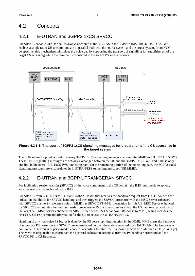
4.2.1 E-UTRAN and 3GPP2 1xCS SRVCC For SRVCC-capable UEs, the call is always anchored at the VCC AS in the 3GPP2's IMS. The 3GPP2 1xCS IWS enables a single radio UE to communicate in parallel both with the source system and the target system. From VCC perspective, this mechanism minimizes the voice gap by supporting the transport of signalling for establishment of the target CS access leg while the terminal is connected to the source PS access network.
Figure 4.2.1-1: Transport of 3GPP2 1xCS signalling messages for preparation of the CS access leg in the target system
The S102 reference point is used to convey 3GPP2 1xCS signalling messages between the MME and 3GPP2 1xCS IWS. These 1x CS signalling messages are actually exchanged between the UE and the 3GPP2 1xCS IWS, and S102 is only one link in the overall UE-1xCS IWS tunnelling path. On the remaining portion of the tunnelling path, the 3GPP2 1xCS signalling messages are encapsulated in E-UTRAN/EPS tunnelling messages (UE-MME).
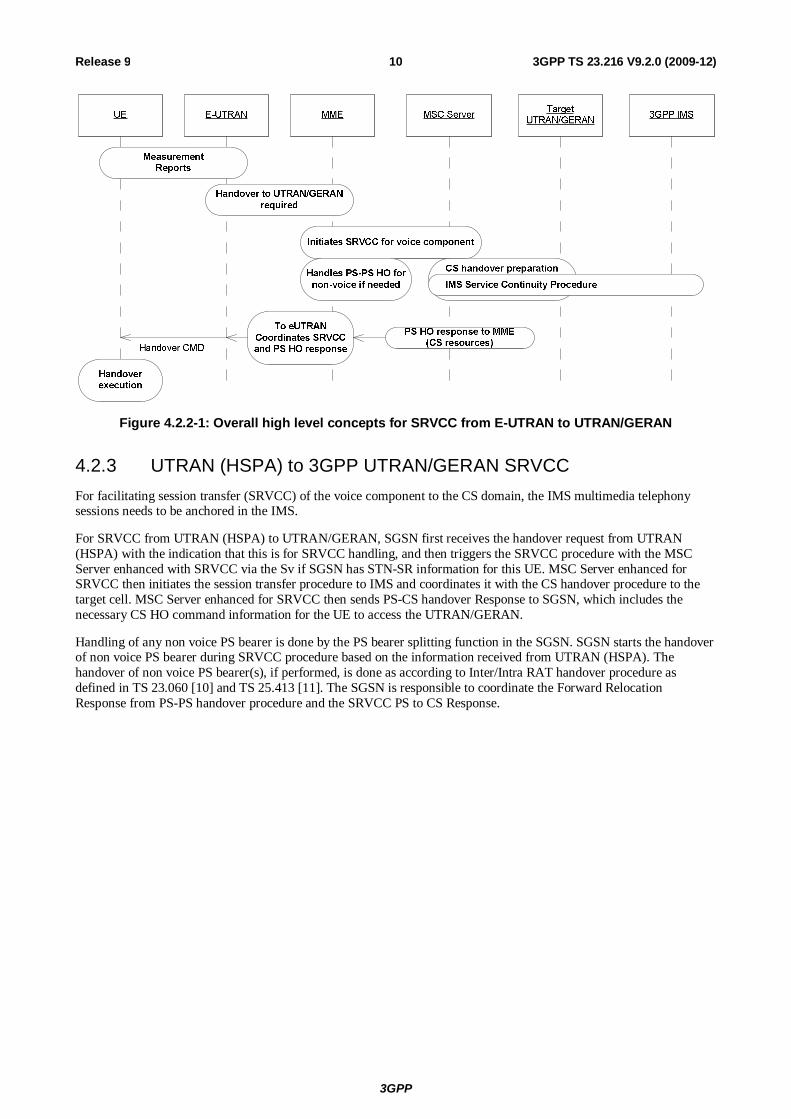
4.2.2 E-UTRAN and 3GPP UTRAN/GERAN SRVCC For facilitating session transfer (SRVCC) of the voice component to the CS domain, the IMS multimedia telephony sessions needs to be anchored in the IMS.
For SRVCC from E-UTRAN to UTRAN/GERAN, MME first receives the handover request from E-UTRAN with the indication that this is for SRVCC handling, and then triggers the SRVCC procedure with the MSC Server enhanced with SRVCC via the Sv reference point if MME has SRVCC STN-SR information for this UE. MSC Server enhanced for SRVCC then initiates the session transfer procedure to IMS and coordinates it with the CS handover procedure to the target cell. MSC Server enhanced for SRVCC then sends PS-CS handover Response to MME, which includes the necessary CS HO command information for the UE to access the UTRAN/GERAN.
Handling of any non-voice PS bearer is done by the PS bearer splitting function in the MME. MME starts the handover of non-voice PS bearer during SRVCC procedure based on the information received from E-UTRAN. The handover of non-voice PS bearer(s), if performed, is done as according to Inter RAT handover procedure as defined in TS 23.401 [2]. The MME is responsible to coordinate the Forward Relocation Response from PS-PS handover procedure and the SRVCC PS to CS Response.
3GPP
3GPP TS 23.216 V9.2.0 (2009-12) 10Release 9
Figure 4.2.2-1: Overall high level concepts for SRVCC from E-UTRAN to UTRAN/GERAN
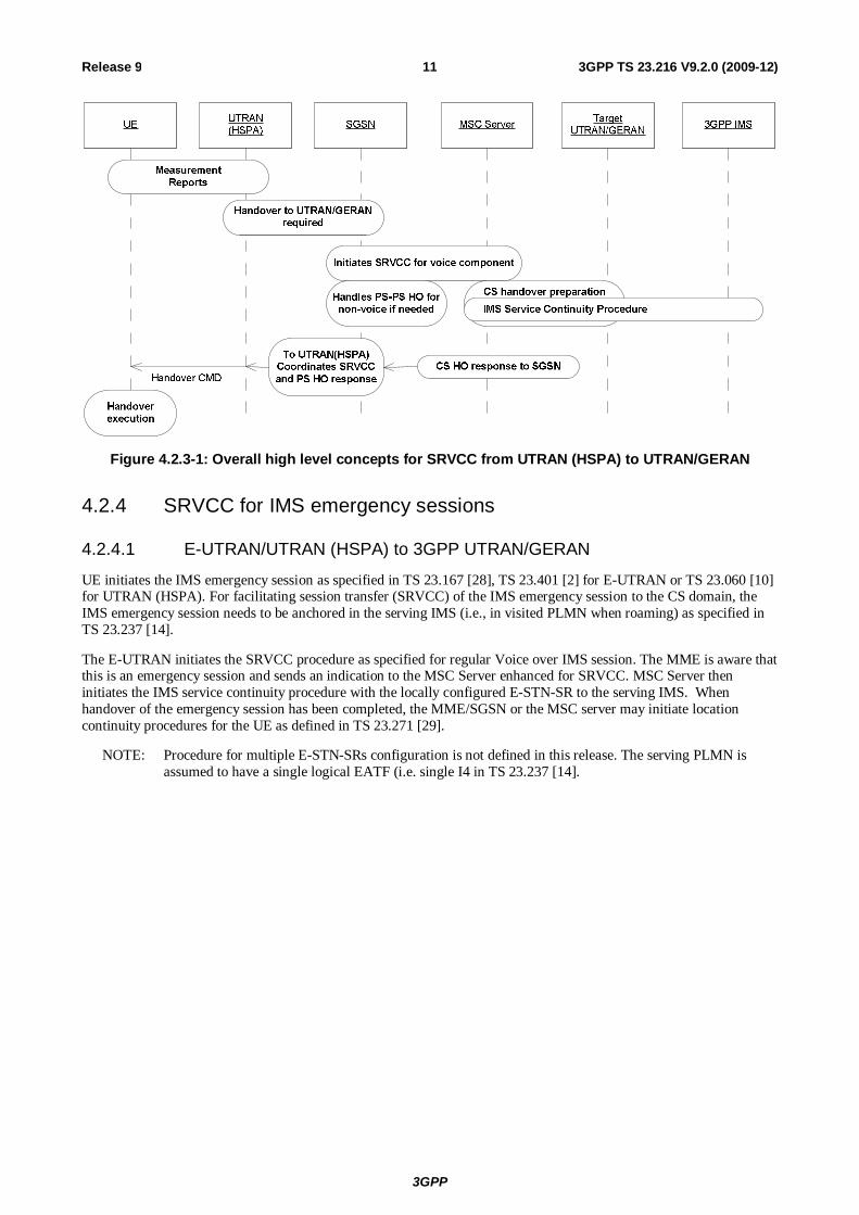
4.2.3 UTRAN (HSPA) to 3GPP UTRAN/GERAN SRVCC For facilitating session transfer (SRVCC) of the voice component to the CS domain, the IMS multimedia telephony sessions needs to be anchored in the IMS.
For SRVCC from UTRAN (HSPA) to UTRAN/GERAN, SGSN first receives the handover request from UTRAN (HSPA) with the indication that this is for SRVCC handling, and then triggers the SRVCC procedure with the MSC Server enhanced with SRVCC via the Sv if SGSN has STN-SR information for this UE. MSC Server enhanced for SRVCC then initiates the session transfer procedure to IMS and coordinates it with the CS handover procedure to the target cell. MSC Server enhanced for SRVCC then sends PS-CS handover Response to SGSN, which includes the necessary CS HO command information for the UE to access the UTRAN/GERAN.
Handling of any non voice PS bearer is done by the PS bearer splitting function in the SGSN. SGSN starts the handover of non voice PS bearer during SRVCC procedure based on the information received from UTRAN (HSPA). The handover of non voice PS bearer(s), if performed, is done as according to Inter/Intra RAT handover procedure as defined in TS 23.060 [10] and TS 25.413 [11]. The SGSN is responsible to coordinate the Forward Relocation Response from PS-PS handover procedure and the SRVCC PS to CS Response.
3GPP
3GPP TS 23.216 V9.2.0 (2009-12) 11Release 9
Figure 4.2.3-1: Overall high level concepts for SRVCC from UTRAN (HSPA) to UTRAN/GERAN
4.2.4 SRVCC for IMS emergency sessions
4.2.4.1 E-UTRAN/UTRAN (HSPA) to 3GPP UTRAN/GERAN
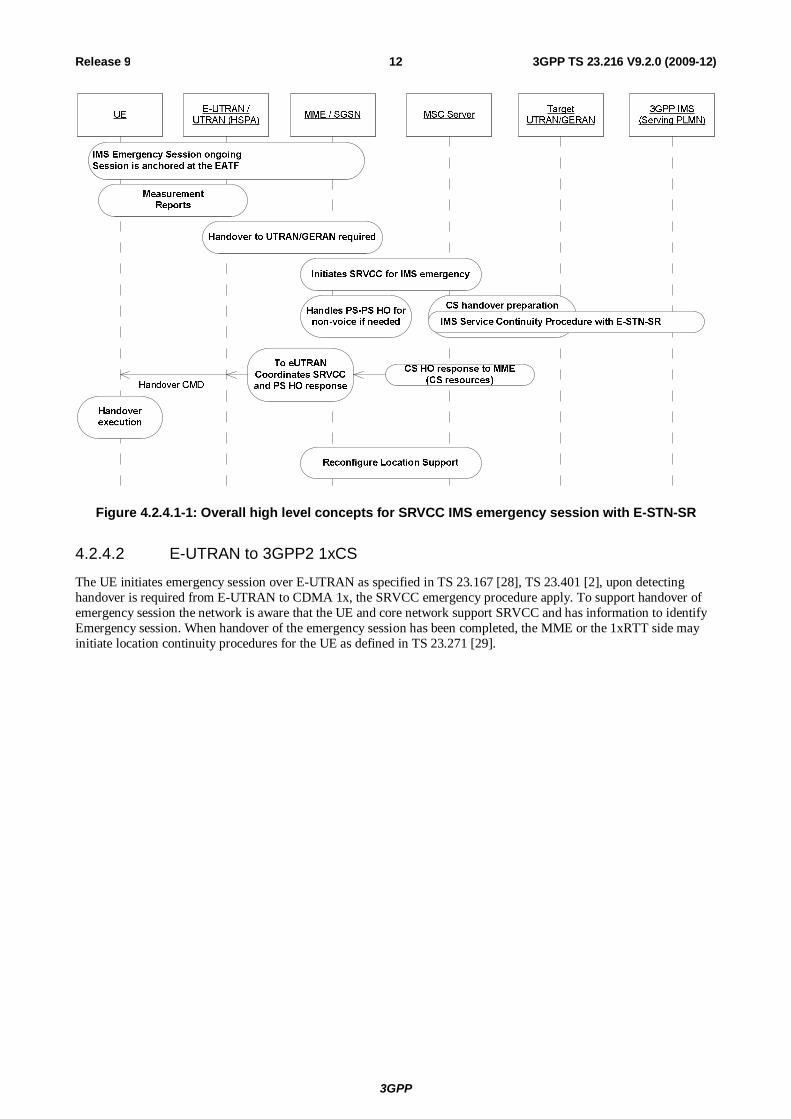
UE initiates the IMS emergency session as specified in TS 23.167 [28], TS 23.401 [2] for E-UTRAN or TS 23.060 [10] for UTRAN (HSPA). For facilitating session transfer (SRVCC) of the IMS emergency session to the CS domain, the IMS emergency session needs to be anchored in the serving IMS (i.e., in visited PLMN when roaming) as specified in TS 23.237 [14].
The E-UTRAN initiates the SRVCC procedure as specified for regular Voice over IMS session. The MME is aware that this is an emergency session and sends an indication to the MSC Server enhanced for SRVCC. MSC Server then initiates the IMS service continuity procedure with the locally configured E-STN-SR to the serving IMS. When handover of the emergency session has been completed, the MME/SGSN or the MSC server may initiate location continuity procedures for the UE as defined in TS 23.271 [29].
NOTE: Procedure for multiple E-STN-SRs configuration is not defined in this release. The serving PLMN is assumed to have a single logical EATF (i.e. single I4 in TS 23.237 [14].
3GPP
3GPP TS 23.216 V9.2.0 (2009-12) 12Release 9
Figure 4.2.4.1-1: Overall high level concepts for SRVCC IMS emergency session with E-STN-SR
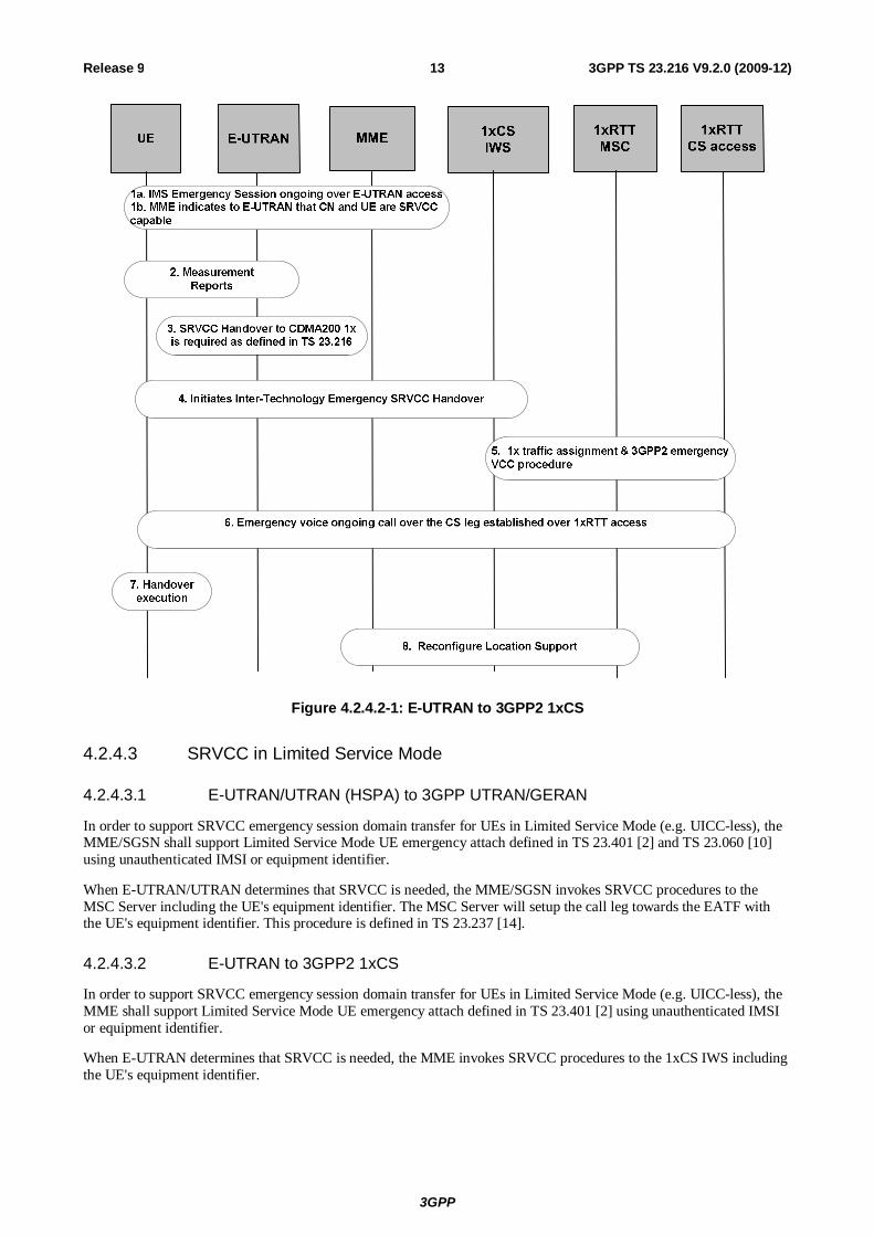
4.2.4.2 E-UTRAN to 3GPP2 1xCS
The UE initiates emergency session over E-UTRAN as specified in TS 23.167 [28], TS 23.401 [2], upon detecting handover is required from E-UTRAN to CDMA 1x, the SRVCC emergency procedure apply. To support handover of emergency session the network is aware that the UE and core network support SRVCC and has information to identify Emergency session. When handover of the emergency session has been completed, the MME or the 1xRTT side may initiate location continuity procedures for the UE as defined in TS 23.271 [29].
3GPP
3GPP TS 23.216 V9.2.0 (2009-12) 13Release 9
Figure 4.2.4.2-1: E-UTRAN to 3GPP2 1xCS
4.2.4.3 SRVCC in Limited Service Mode
4.2.4.3.1 E-UTRAN/UTRAN (HSPA) to 3GPP UTRAN/GERAN
In order to support SRVCC emergency session domain transfer for UEs in Limited Service Mode (e.g. UICC-less), the MME/SGSN shall support Limited Service Mode UE emergency attach defined in TS 23.401 [2] and TS 23.060 [10] using unauthenticated IMSI or equipment identifier.
When E-UTRAN/UTRAN determines that SRVCC is needed, the MME/SGSN invokes SRVCC procedures to the MSC Server including the UE's equipment identifier. The MSC Server will setup the call leg towards the EATF with the UE's equipment identifier. This procedure is defined in TS 23.237 [14].
4.2.4.3.2 E-UTRAN to 3GPP2 1xCS
In order to support SRVCC emergency session domain transfer for UEs in Limited Service Mode (e.g. UICC-less), the MME shall support Limited Service Mode UE emergency attach defined in TS 23.401 [2] using unauthenticated IMSI or equipment identifier.
When E-UTRAN determines that SRVCC is needed, the MME invokes SRVCC procedures to the 1xCS IWS including the UE's equipment identifier.
3GPP
3GPP TS 23.216 V9.2.0 (2009-12) 14Release 9
5 Architecture model and reference points
5.1 General The SRVCC Architecture for 3GPP2 1xCS reuses many existing elements in 3GPP2 X.S0042 [4] for 3GPP2 1xCS.
The SRVCC Architecture for 3GPP UTRAN/GERAN reuses the session transfer function defined for IMS in TS 23.237 [14] for IMS service continuity. The MSC Server that is enhanced for SRVCC may also be enhanced for ICS as defined in TS 23.292 [13].
The overall model and impacts to the various elements is provided in the following clauses.
5.2 Reference architecture
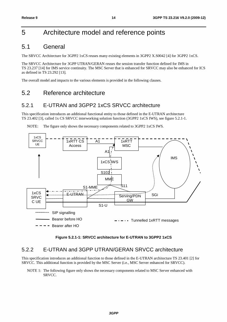
5.2.1 E-UTRAN and 3GPP2 1xCS SRVCC architecture This specification introduces an additional functional entity to those defined in the E-UTRAN architecture TS 23.402 [3], called 1x CS SRVCC interworking solution function (3GPP2 1xCS IWS), see figure 5.2.1-1.
NOTE: The figure only shows the necessary components related to 3GPP2 1xCS IWS.
E-UTRAN
MME
Serving/PDN GW
SGi
1xRTT CS Access
1xRTT MSC
1xCS IWS
S102
S11 S1-MME
S1-U
A1
1xCS SRVCC UE
Bearer before HO
Bearer after HO
SIP signalling
A1
IMS
Tunnelled 1xRTT messages
1xCS SRVCC
UE
Figure 5.2.1-1: SRVCC architecture for E-UTRAN to 3GPP2 1xCS
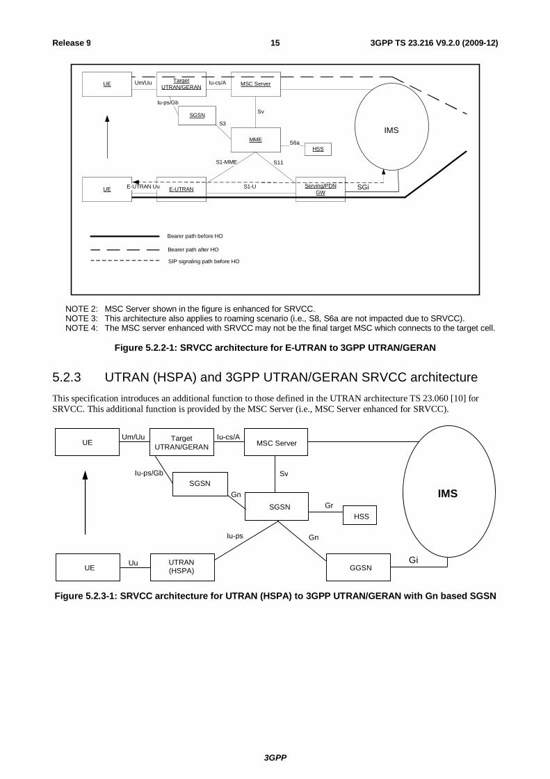
5.2.2 E-UTRAN and 3GPP UTRAN/GERAN SRVCC architecture This specification introduces an additional function to those defined in the E-UTRAN architecture TS 23.401 [2] for SRVCC. This additional function is provided by the MSC Server (i.e., MSC Server enhanced for SRVCC).
NOTE 1: The following figure only shows the necessary components related to MSC Server enhanced with SRVCC.
3GPP
3GPP TS 23.216 V9.2.0 (2009-12) 15Release 9
UE E-UTRAN
MME
MSC ServerTarget UTRAN/GERAN
Serving/PDNGW
IMS
UE Um/Uu Iu-cs/A
S3
Sv
S11S1-MME
S1-UE-UTRAN Uu SGi
HSSS6a
SGSN
Iu-ps/Gb
Bearer path before HO
Bearer path after HO
SIP signaling path before HO
NOTE 2: MSC Server shown in the figure is enhanced for SRVCC. NOTE 3: This architecture also applies to roaming scenario (i.e., S8, S6a are not impacted due to SRVCC). NOTE 4: The MSC server enhanced with SRVCC may not be the final target MSC which connects to the target cell.
Figure 5.2.2-1: SRVCC architecture for E-UTRAN to 3GPP UTRAN/GERAN
5.2.3 UTRAN (HSPA) and 3GPP UTRAN/GERAN SRVCC architecture This specification introduces an additional function to those defined in the UTRAN architecture TS 23.060 [10] for SRVCC. This additional function is provided by the MSC Server (i.e., MSC Server enhanced for SRVCC).
UE Target
UTRAN/GERAN MSC Server
SGSN
SGSN HSS
GGSN UTRAN (HSPA) UE
IMS
Uu
Um/Uu Iu-cs/A
Iu-ps/Gb
Gn
Sv
Gr
Gn
Gi
Iu-ps
Figure 5.2.3-1: SRVCC architecture for UTRAN (HSPA) to 3GPP UTRAN/GERAN with Gn based SGSN
3GPP
3GPP TS 23.216 V9.2.0 (2009-12) 16Release 9
UE Target
UTRAN/GERAN MSC Server
SGSN
SGSN HSS
Serving/PDN GW
UTRAN (HSPA) UE
IMS
Uu
Um/Uu Iu-cs/A
Iu-ps/Gb
S16
Sv
Gr
S4
SGi
Iu-ps
S12
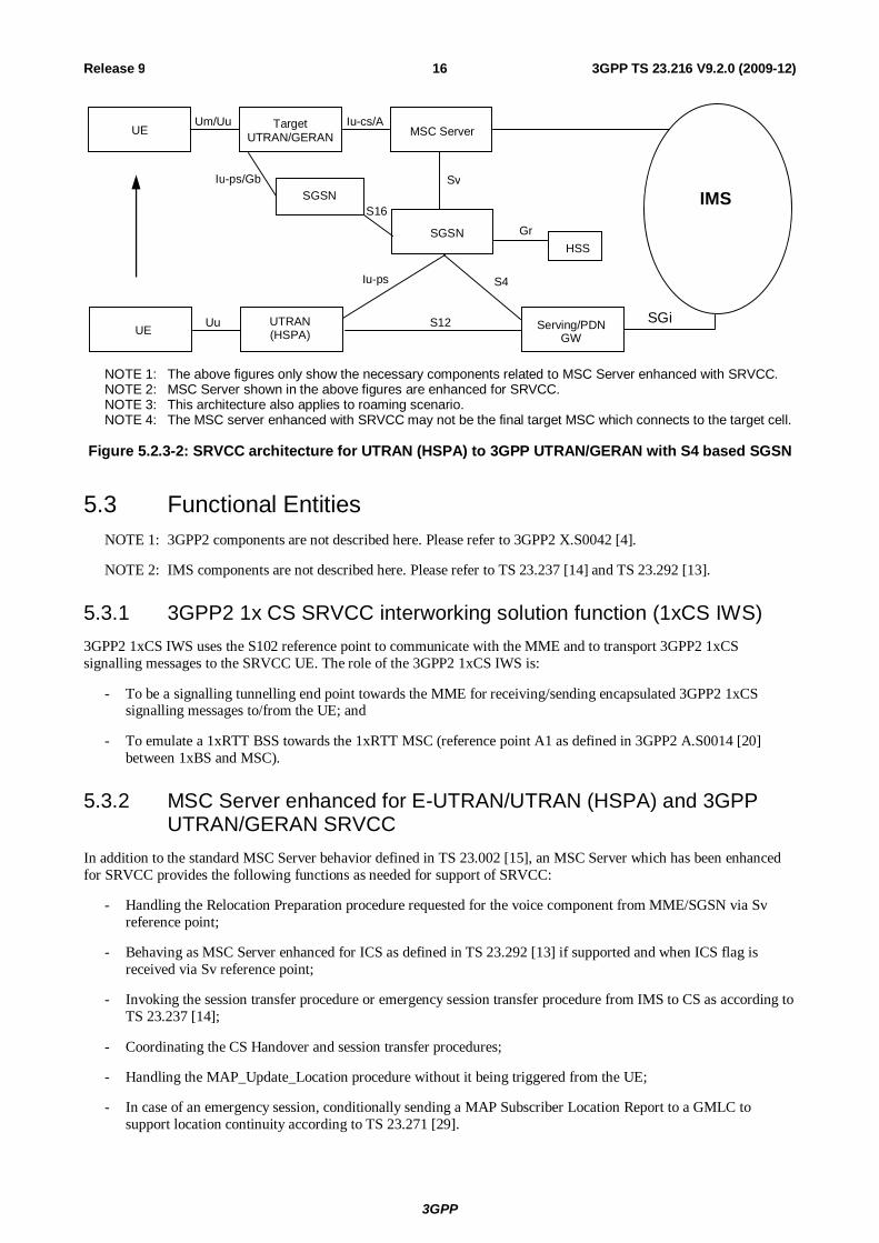
NOTE 1: The above figures only show the necessary components related to MSC Server enhanced with SRVCC. NOTE 2: MSC Server shown in the above figures are enhanced for SRVCC. NOTE 3: This architecture also applies to roaming scenario. NOTE 4: The MSC server enhanced with SRVCC may not be the final target MSC which connects to the target cell.
Figure 5.2.3-2: SRVCC architecture for UTRAN (HSPA) to 3GPP UTRAN/GERAN with S4 based SGSN
5.3 Functional Entities NOTE 1: 3GPP2 components are not described here. Please refer to 3GPP2 X.S0042 [4].
NOTE 2: IMS components are not described here. Please refer to TS 23.237 [14] and TS 23.292 [13].
5.3.1 3GPP2 1x CS SRVCC interworking solution function (1xCS IWS) 3GPP2 1xCS IWS uses the S102 reference point to communicate with the MME and to transport 3GPP2 1xCS signalling messages to the SRVCC UE. The role of the 3GPP2 1xCS IWS is:
- To be a signalling tunnelling end point towards the MME for receiving/sending encapsulated 3GPP2 1xCS signalling messages to/from the UE; and
- To emulate a 1xRTT BSS towards the 1xRTT MSC (reference point A1 as defined in 3GPP2 A.S0014 [20] between 1xBS and MSC).
5.3.2 MSC Server enhanced for E-UTRAN/UTRAN (HSPA) and 3GPP UTRAN/GERAN SRVCC
In addition to the standard MSC Server behavior defined in TS 23.002 [15], an MSC Server which has been enhanced for SRVCC provides the following functions as needed for support of SRVCC:
- Handling the Relocation Preparation procedure requested for the voice component from MME/SGSN via Sv reference point;
- Behaving as MSC Server enhanced for ICS as defined in TS 23.292 [13] if supported and when ICS flag is received via Sv reference point;
- Invoking the session transfer procedure or emergency session transfer procedure from IMS to CS as according to TS 23.237 [14];
- Coordinating the CS Handover and session transfer procedures;
- Handling the MAP_Update_Location procedure without it being triggered from the UE;
- In case of an emergency session, conditionally sending a MAP Subscriber Location Report to a GMLC to support location continuity according to TS 23.271 [29].
3GPP
3GPP TS 23.216 V9.2.0 (2009-12) 17Release 9
5.3.3 MME
5.3.3.1 Interworking with 3GPP2 1xCS IWS
If the MME (operator) supports interworking to 3GPP2 1xCS, the MME shall follow the rules and procedures described in TS 23.402 [3] with the following additions and clarifications:
- To be a signalling tunnelling end point towards the 3GPP2 1xCS IWS for sending/receiving encapsulated 3GPP2 1xCS signalling messages to/from the UE, which are encapsulated in S1-MME S1 Information Transfer messages (TR 36.938 [7]).
- release of the E-UTRAN resources after SRVCC to the 3GPP2 1xCS is completed.
- include information to enable 3GPP2 network to determine emergency session.
- insert the equipment identifier during the handover procedure for the case UE operating in limited service mode.
5.3.3.2 Interworking with 3GPP MSC Server enhanced for SRVCC
5.3.3.2.1 Interworking with 3GPP MSC Server enhanced for SRVCC
If the MME (operator) supports the interworking to 3GPP CS, the MME shall follow the rules and procedures described in TS 23.401 [2] with the following additions and clarifications:
- Performing the PS bearer splitting function by separating the voice PS bearer from the non-voice PS bearers.
- Handling the non-voice PS bearers handover with the target cell as according to Inter RAT handover procedure as defined in TS 23.401 [2].
- Initiating the SRVCC handover procedure for handover of the voice component to the target cell via the Sv interface and including an emergency indication if this is an emergency session. This procedure is only triggered once regardless of the number of voice bearers (i.e. QCI=1) that are in use by the UE. If there are multiple voice bearers and one of those is for IMS emergency session then MME shall only execute the SRVCC for emergency.
- Coordinating PS handover and SRVCC handover procedures when both procedures are performed.
- Sending the equipment identifier to the MSC Server during the handover procedure for the case of UEs operating in limited service mode.
- In case of an emergency session, conditionally sending a Subscriber Location Report to a GMLC to support location continuity according to TS 23.271 [29].
5.3.3.2.2 PS bearer splitting function
The function identifies the voice PS bearer upon E-UTRAN to UTRAN/GERAN SRVCC and performs different handling of these bearers from the non-voice PS bearers (see detailed procedures in subsequent clauses).
5.3.3A SGSN
5.3.3A.1 Interworking with 3GPP MSC Server enhanced for SRVCC
5.3.3A.1.1 Interworking with 3GPP MSC Server enhanced for SRVCC
If the SGSN (operator) supports the interworking to 3GPP CS, the SGSN shall follow the rules and procedures described in TS 23.060 [10] with the following additions and clarifications:
- Performing the PS bearer splitting function by separating the voice PS bearer from the non-voice PS bearers. VoIP is detected by traffic class=conversational and SSD='speech'.
- Handling the non-voice PS bearers handover with the target cell as according to Inter/Intra RAT handover procedure as defined in TS 23.060 [10].
3GPP
3GPP TS 23.216 V9.2.0 (2009-12) 18Release 9
- Initiating the SRVCC handover procedure for handover of the voice component to the target cell via the Sv interface and including an emergency indication if this is an emergency session. This process is only triggered once regardless of the number of PS voice bearers (i.e. SSD='speech') that are in use by the UE. If there are multiple voice bearers and one of those is for IMS emergency session then SGSN shall only execute the SRVCC for emergency.
- Coordinating PS handover and SRVCC handover procedures when both procedures are performed.
- Sending the equipment identifier to the MSC Server during the handover procedure for the case of UEs operating in limited service mode.
- In case of an emergency session, conditionally sending a MAP Subscriber Location Report to a GMLC to support location continuity according to TS 23.271 [29].
5.3.3A.1.2 PS bearer splitting function
The function identifies the voice PS bearer upon HSPA to UTRAN/GERAN SRVCC and performs different handling on these bearers from the non-voice PS bearers (see detailed procedures in subsequent clauses).
5.3.4 UE enhanced for SRVCC
5.3.4.1 Interworking with 3GPP2 1xCS
If the UE supports 3GPP2 1xCS access, the 1xCS SRVCC UE is a UE that is capable to perform SRVCC to the 3GPP2 1xCS system. The interaction between UE and E-UTRAN is described in TR 36.938 [7]. The interaction with the 3GPP2 1xCS system is described in this specification.
5.3.4.2 Interworking with 3GPP UTRAN/GERAN
3GPP SRVCC UE is needed to perform SRVCC (see clause 3.1 for 3GPP SRVCC UE definition). The interaction between UE and E-UTRAN is described in TS 36.300 [16] and between UE and UTRAN (HSPA) is described in TS 25.331 [19].
The SRVCC UE indicates to the network that the UE is SRVCC capable when being configured for using IMS speech service supported by the home operator, e.g. the IMS Multimedia Telephony Service for bi-directional speech as described in TS 22.173 [26] and the operator policy on the SRVCC UE as specified in TS 23.237 [14] does not restrict the session transfer.
5.3.5 Serving/PDN GW No additional requirement due to SRVCC.
5.3.6 E-UTRAN
5.3.6.1 Interworking with 3GPP2 1xCS
If the E-UTRAN (operator) supports interworking to 3GPP2 1xCS, the E-UTRAN performs the HO trigger, tunnelling of the 3GPP2 1xCS signalling messages toward the MME, and interacting with the SRVCC UE as described in TR 36.938 [7].
E-UTRAN may be capable of determining the neighbour cell list based on the "SRVCC operation possible" indication and/or presence of established QCI=1 bearers for a specific UE. An example algorithm is provided in clause A.1.
NOTE: If E-UTRAN does not update the neighbour cell list dynamically, if E-UTRAN triggers handover to 1x when either the "SRVCC operation possible" indication is set to "false" or there are no established QCI=1 bearers for a specific UE, this will result in an error case.
5.3.6.2 Interworking with 3GPP UTRAN/GERAN
Between UE and E-UTRAN, no additional functionality is required for the E-UTRAN as defined in TS 36.300 [16].
3GPP
3GPP TS 23.216 V9.2.0 (2009-12) 19Release 9
When E-UTRAN selects a target cell for SRVCC handover, it needs to send an indication to MME that this handover procedure requires SRVCC
E-UTRAN may be capable of determining the neighbour cell list based on the "SRVCC operation possible" indication and/or presence of established QCI=1 bearers for a specific UE. An example algorithm is provided in clause A.2.
NOTE: In case E-UTRAN does not update the neighbour cell list dynamically, if E-UTRAN triggers handover to a VoIP-incapable cell when the "SRVCC operation possible" indication is set to "false" and there are established voice (QCI=1) bearers for a specific UE, the establishment of the voice bearers will be rejected by the target access.
5.3.6A UTRAN (HSPA) When HSPA capable UTRAN selects a target cell for SRVCC handover, it needs to send an indication to SGSN that this handover procedure requires SRVCC.
NOTE 1: UTRAN (HSPA) assumes that SGSN supports SRVCC functionality.
UTRAN may be capable of determining the neighbour cell list based on the "SRVCC operation possible" indication and/or presence of established voice bearers (i.e. bearers with Traffic Class = Conversational and Source Statistic Descriptor = 'speech') for a specific UE. An example algorithm is provided in clause A.3.
NOTE 2: In case UTRAN does not update the neighbour cell list dynamically, if UTRAN triggers handover to a VoIP-incapable cell when the "SRVCC operation possible" indication is set to "false" and there are established bearers with Traffic Class = Conversational and Source Statistic Descriptor = 'speech' for a specific UE, the establishment of the voice bearers will be rejected by the target access.
5.3.7 HSS
5.3.7.1 Interworking with 3GPP UTRAN/GERAN
The SRVCC STN-SR, C-MSISDN and optional ICS flag are downloaded to MME from HSS during E-UTRAN attach procedure. For UTRAN (HSPA), these subscription information are downloaded to SGSN from HSS during GPRS attach procedure. HSS also informs the MME/SGSN when STN-SR is modified or removed from the subscription.
The ICS flag is used by the MSC Server enhanced for SRVCC to behave also as MSC Server enhanced for ICS in TS 23.292 [13] if supported by the network.
NOTE: HSS functionality is not impacted when MSC Server enhanced with SRVCC performs the MAP_Update_Location procedure.
5.4 Reference points
5.4.1 MME – 3GPP2 1xCS IWS (S102) The S102 reference point provides a tunnel between MME and 3GPP2 1xCS IWS to relay 3GPP2 1xCS signalling messages. 1x CS signalling messages are those messages that are defined for A21 interface as described in 3GPP2 A.S0008-C [8].
NOTE. It is up to stage 3 to determine whether the tunnelling protocol for S102 can be defined as exactly as in A21. If so, S102 is then equivalent to A21.
5.4.2 MME/SGSN – MSC Server (Sv) The Sv reference point provides SRVCC support between 3GPP E-UTRAN/UTRAN (HSPA) and 3GPP UTRAN/GERAN.
MME/SGSN includes the optional ICS flag if received from the HSS.
3GPP
3GPP TS 23.216 V9.2.0 (2009-12) 20Release 9
5.4.3 E-UTRAN – MME (S1-MME) For 3GPP2 1xCS SRVCC, the S1-MME reference point provides S1 Information Transfer message (TR 36.938 [7]) between UE and MME to relay the 3GPP2 1xCS signalling messages.
For 3GPP SRVCC, the S1-MME reference point allows handover signalling between E-UTRAN and MME. It is defined in TS 36.300 [16]
5.4.3A UTRAN (HSPA) – SGSN (Iu-ps) For 3GPP HSPA SRVCC, the Iu-ps reference point allows handover signalling between UTRAN and SGSN. It is defined in TS 25.413 [11].
5.4.4 HSS – MME (S6a) For 3GPP SRVCC, the S6a is used to download SRVCC related information to MME during E-UTRAN attach procedure or to inform MME that STN-SR information in the HSS has changed.
5.4.5 HSS – SGSN (Gr) For 3GPP SRVCC, the Gr is used to download SRVCC related information to SGSN during UTRAN (HSPA) attach procedure or to inform SGSN that STN-SR information in the HSS has changed.
6 Procedures and flows
6.1 SRVCC from E-UTRAN to 3GPP2 1xCS
6.1.1 E-UTRAN Attach procedure for SRVCC E-UTRAN attach or emergency attach procedure for 3GPP2 SRVCC UE is performed as defined in TS 23.401 [2] with the following additions:
- SRVCC UE includes the SRVCC capability indication as part of the "UE Network Capability" in the Attach Request message. MME stores this information for SRVCC operation.
- SRVCC UE capable for IMS emergency calls shall include the SRVCC capability indication as part of the UE network capability in the Emergency Attach Request message. MME stores this information for emergency SRVCC operation.
- MME includes a "SRVCC operation possible" indication in the S1 AP Initial Context Setup Request, meaning that both UE and MME are SRVCC-capable.
6.1.2 Service Request procedures for SRVCC Service Request procedures for 3GPP2 SRVCC UE are performed as defined in TS 23.401 [2] with the following additions:
- MME includes a "SRVCC operation possible" indication in the S1 AP Initial Context Setup Request, meaning that both UE and MME are SRVCC-capable.
6.1.3 Call flows for SRVCC from E-UTRAN Figure 6.1.3-1 illustrates a high-level call flow for the E-UTRAN-to-1x voice service continuity procedure.
3GPP
3GPP TS 23.216 V9.2.0 (2009-12) 21Release 9
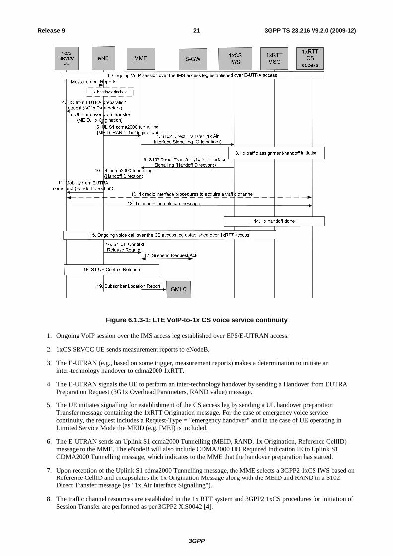
Figure 6.1.3-1: LTE VoIP-to-1x CS voice service continuity
1. Ongoing VoIP session over the IMS access leg established over EPS/E-UTRAN access.
2. 1xCS SRVCC UE sends measurement reports to eNodeB.
3. The E-UTRAN (e.g., based on some trigger, measurement reports) makes a determination to initiate an inter-technology handover to cdma2000 1xRTT.
4. The E-UTRAN signals the UE to perform an inter-technology handover by sending a Handover from EUTRA Preparation Request (3G1x Overhead Parameters, RAND value) message.
5. The UE initiates signalling for establishment of the CS access leg by sending a UL handover preparation Transfer message containing the 1xRTT Origination message. For the case of emergency voice service continuity, the request includes a Request-Type = "emergency handover" and in the case of UE operating in Limited Service Mode the MEID (e.g. IMEI) is included.
6. The E-UTRAN sends an Uplink S1 cdma2000 Tunnelling (MEID, RAND, 1x Origination, Reference CellID) message to the MME. The eNodeB will also include CDMA2000 HO Required Indication IE to Uplink S1 CDMA2000 Tunnelling message, which indicates to the MME that the handover preparation has started.
7. Upon reception of the Uplink S1 cdma2000 Tunnelling message, the MME selects a 3GPP2 1xCS IWS based on Reference CellID and encapsulates the 1x Origination Message along with the MEID and RAND in a S102 Direct Transfer message (as "1x Air Interface Signalling").
8. The traffic channel resources are established in the 1x RTT system and 3GPP2 1xCS procedures for initiation of Session Transfer are performed as per 3GPP2 X.S0042 [4].
3GPP
3GPP TS 23.216 V9.2.0 (2009-12) 22Release 9
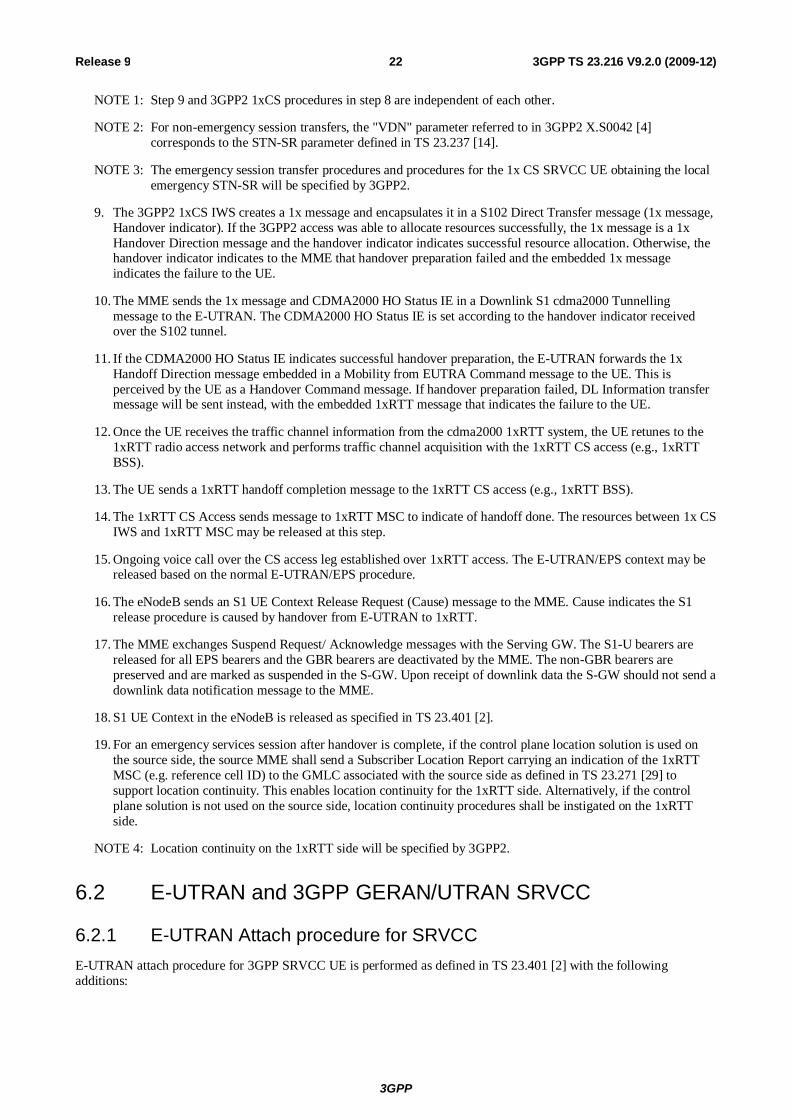
NOTE 1: Step 9 and 3GPP2 1xCS procedures in step 8 are independent of each other.
NOTE 2: For non-emergency session transfers, the "VDN" parameter referred to in 3GPP2 X.S0042 [4] corresponds to the STN-SR parameter defined in TS 23.237 [14].
NOTE 3: The emergency session transfer procedures and procedures for the 1x CS SRVCC UE obtaining the local emergency STN-SR will be specified by 3GPP2.
9. The 3GPP2 1xCS IWS creates a 1x message and encapsulates it in a S102 Direct Transfer message (1x message, Handover indicator). If the 3GPP2 access was able to allocate resources successfully, the 1x message is a 1x Handover Direction message and the handover indicator indicates successful resource allocation. Otherwise, the handover indicator indicates to the MME that handover preparation failed and the embedded 1x message indicates the failure to the UE.
10. The MME sends the 1x message and CDMA2000 HO Status IE in a Downlink S1 cdma2000 Tunnelling message to the E-UTRAN. The CDMA2000 HO Status IE is set according to the handover indicator received over the S102 tunnel.
11. If the CDMA2000 HO Status IE indicates successful handover preparation, the E-UTRAN forwards the 1x Handoff Direction message embedded in a Mobility from EUTRA Command message to the UE. This is perceived by the UE as a Handover Command message. If handover preparation failed, DL Information transfer message will be sent instead, with the embedded 1xRTT message that indicates the failure to the UE.
12. Once the UE receives the traffic channel information from the cdma2000 1xRTT system, the UE retunes to the 1xRTT radio access network and performs traffic channel acquisition with the 1xRTT CS access (e.g., 1xRTT BSS).
13. The UE sends a 1xRTT handoff completion message to the 1xRTT CS access (e.g., 1xRTT BSS).
14. The 1xRTT CS Access sends message to 1xRTT MSC to indicate of handoff done. The resources between 1x CS IWS and 1xRTT MSC may be released at this step.
15. Ongoing voice call over the CS access leg established over 1xRTT access. The E-UTRAN/EPS context may be released based on the normal E-UTRAN/EPS procedure.
16. The eNodeB sends an S1 UE Context Release Request (Cause) message to the MME. Cause indicates the S1 release procedure is caused by handover from E-UTRAN to 1xRTT.
17. The MME exchanges Suspend Request/ Acknowledge messages with the Serving GW. The S1-U bearers are released for all EPS bearers and the GBR bearers are deactivated by the MME. The non-GBR bearers are preserved and are marked as suspended in the S-GW. Upon receipt of downlink data the S-GW should not send a downlink data notification message to the MME.
18. S1 UE Context in the eNodeB is released as specified in TS 23.401 [2].
19. For an emergency services session after handover is complete, if the control plane location solution is used on the source side, the source MME shall send a Subscriber Location Report carrying an indication of the 1xRTT MSC (e.g. reference cell ID) to the GMLC associated with the source side as defined in TS 23.271 [29] to support location continuity. This enables location continuity for the 1xRTT side. Alternatively, if the control plane solution is not used on the source side, location continuity procedures shall be instigated on the 1xRTT side.
NOTE 4: Location continuity on the 1xRTT side will be specified by 3GPP2.
6.2 E-UTRAN and 3GPP GERAN/UTRAN SRVCC
6.2.1 E-UTRAN Attach procedure for SRVCC E-UTRAN attach procedure for 3GPP SRVCC UE is performed as defined in TS 23.401 [2] with the following additions:
3GPP
3GPP TS 23.216 V9.2.0 (2009-12) 23Release 9
- SRVCC UE includes the SRVCC capability indication as part of the "MS Network Capability" in the Attach Request message and in Tracking Area Updates. MME stores this information for SRVCC operation. The procedures are as specified in TS 23.401 [22].
NOTE 1: If the service configuration on the UE is changed (e.g. the user changes between an IMS speech service supported by the home operator and a PS speech service incompatible with SRVCC), the UE can change its SRVCC capability indication as part of the "MS Network Capability" in a Tracking Area Update message.
- SRVCC UE includes the GERAN MS Classmark 3 (if GERAN access is supported), MS Classmark 2 (if GERAN or UTRAN access or both are supported) and Supported Codecs IE (if GERAN or UTRAN access or both are supported) in the Attach Request message and in the non-periodic Tracking Area Update messages.
NOTE 2: MS Classmark 2, 3 and the Supported Codec IE are not sent from the source MME to the target MME/SGSN at inter CN-node mobility.
- If the subscriber is allowed to have SRVCC in the VPLMN then HSS includes SRVCC STN-SR and C-MSISDN as part of the subscription data sent to the MME.
- MME includes a "SRVCC operation possible" indication in the S1 AP Initial Context Setup Request, meaning that both UE and MME are SRVCC-capable.
E-UTRAN emergency attach procedure for 3GPP SRVCC UE is performed as defined in TS 23.401 [2] and above with the following clarifications:
- SRVCC UE shall include the SRVCC capability indication as part of the "MS Network Capability" in the Emergency Attach Request message, and maintained during Tracking Area Updates. MME stores this information for SRVCC operation. The procedures are as specified in TS 23.401 [22].
6.2.1A Service Request procedures for SRVCC Service Request procedures for 3GPP SRVCC UE are performed as defined in TS 23.401 [2] with the following additions:
- MME includes a "SRVCC operation possible" indication in the S1 AP Initial Context Setup Request, meaning that both UE and MME are SRVCC-capable.
6.2.2 Call flows for SRVCC from E-UTRAN NOTE 1: If the MSC Server enhanced for SRVCC controls the target BSS/RNS, the steps depicted with dot-dashed
arrows representing the MSC-MSC handover procedure defined in TS 23.009 [18] are not executed and the functions of the MSC Server enhanced for SRVCC are merged with those of the target MSC.
NOTE 2: For the sake of brevity the call flow descriptions use "MSC Server" instead of "MSC Server enhanced for SRVCC".
NOTE 3: The target MSC need not be enhanced for SRVCC.
6.2.2.1 SRVCC from E-UTRAN to GERAN without DTM support
Depicted in figure 6.2.2.1-1 is a call flow for SRVCC from E-UTRAN to GERAN without DTM support.
3GPP
3GPP TS 23.216 V9.2.0 (2009-12) 24Release 9
UE Source E-UTRAN
Source MME
MSC Server/ MGW
Target MSC
14. Handover Command
Target BSS
1. Measurement reports
3. Handover Required
SGW
2. Decision for HO
5.PS to CS Req 6.Prep HO Req
7. HO Request/Ack
8.Prep HO Resp
9. Establish circuit
19. HO Complete
20.SES (HO Complete)
21. ANSWER
13.PS to CS Resp
15. HO from EUTRAN command
HSS/ HLR
23a.UpdateLoc
10. Initiation of Session Transfer (STN-SR or E-STN-SR)
11. Session transfer and Update remote end
IMS (SCC AS)
12. Release of IMS access leg
22. PS to CS Complete/Ack
Target SGSN
16. UE tunes to GERAN
17. HO Detection 18. Suspend (see TS 23.060)
18. Suspend 18. Suspend Request / Response
18. Update Bearer
4. Bearer Splitting
GMLC 24. Subscriber Location Report
23b. TMSI Reallocation
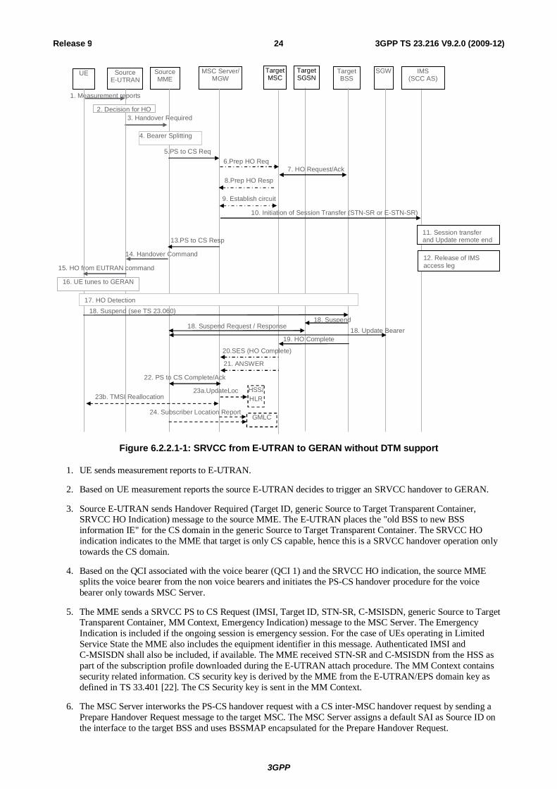
Figure 6.2.2.1-1: SRVCC from E-UTRAN to GERAN without DTM support
1. UE sends measurement reports to E-UTRAN.
2. Based on UE measurement reports the source E-UTRAN decides to trigger an SRVCC handover to GERAN.
3. Source E-UTRAN sends Handover Required (Target ID, generic Source to Target Transparent Container, SRVCC HO Indication) message to the source MME. The E-UTRAN places the "old BSS to new BSS information IE" for the CS domain in the generic Source to Target Transparent Container. The SRVCC HO indication indicates to the MME that target is only CS capable, hence this is a SRVCC handover operation only towards the CS domain.
4. Based on the QCI associated with the voice bearer (QCI 1) and the SRVCC HO indication, the source MME splits the voice bearer from the non voice bearers and initiates the PS-CS handover procedure for the voice bearer only towards MSC Server.
5. The MME sends a SRVCC PS to CS Request (IMSI, Target ID, STN-SR, C-MSISDN, generic Source to Target Transparent Container, MM Context, Emergency Indication) message to the MSC Server. The Emergency Indication is included if the ongoing session is emergency session. For the case of UEs operating in Limited Service State the MME also includes the equipment identifier in this message. Authenticated IMSI and C-MSISDN shall also be included, if available. The MME received STN-SR and C-MSISDN from the HSS as part of the subscription profile downloaded during the E-UTRAN attach procedure. The MM Context contains security related information. CS security key is derived by the MME from the E-UTRAN/EPS domain key as defined in TS 33.401 [22]. The CS Security key is sent in the MM Context.
6. The MSC Server interworks the PS-CS handover request with a CS inter-MSC handover request by sending a Prepare Handover Request message to the target MSC. The MSC Server assigns a default SAI as Source ID on the interface to the target BSS and uses BSSMAP encapsulated for the Prepare Handover Request.
3GPP
3GPP TS 23.216 V9.2.0 (2009-12) 25Release 9
NOTE 1: The value of the default SAI is configured in the MSC and allows a release 8 and later BSC to identify that the source for the SRVCC Handover is E-UTRAN. To ensure correct statistics in the target BSS the default SAI should be different from the SAIs used in UTRAN.
7. Target MSC performs resource allocation with the target BSS by exchanging Handover Request/ Acknowledge messages.
8. Target MSC sends a Prepare Handover Response message to the MSC Server.
9. Establishment of circuit connection between the target MSC and the MGW associated with the MSC Server e.g. using ISUP IAM and ACM messages.
10. For non-emergency session, the MSC Server initiates the Session Transfer by using the STN-SR e.g. by sending an ISUP IAM (STN-SR) message towards the IMS. For emergency session, the MSC Server initiates the Session Transfer by using the locally configured E-STN-SR. Standard IMS Service Continuity or Emergency IMS Service Continuity procedures are applied for execution of the Session Transfer, see TS 23.237 [14].
NOTE 2: This step can be started after step 8.
NOTE 3: If the MSC Server is using an ISUP interface, then the initiation of the session transfer for non-emergency session may fail if the subscriber profile including CAMEL triggers is not available prior handover (see clause 7.3.2.1.3 in TS 23.292 [13]).
11. During the execution of the Session Transfer procedure the remote end is updated with the SDP of the CS access leg. The downlink flow of VoIP packets is switched towards the CS access leg at this point.
12. Source IMS access leg is released as per TS 23.237 [14].
NOTE 4: Steps 11 and 12 are independent of step 13.
13. MSC Server sends a SRVCC PS to CS Response (Target to Source Transparent Container) message to the source MME.
14. Source MME sends a Handover Command (Target to Source Transparent Container) message to the source E-UTRAN. The message includes information about the voice component only.
15. Source E-UTRAN sends a Handover from E-UTRAN Command message to the UE.
16. UE tunes to GERAN.
17. Handover Detection at the target BSS occurs. The UE sends a Handover Complete message via the target BSS to the target MSC. If the target MSC is not the MSC Server, then the Target MSC sends an SES (Handover Complete) message to the MSC Server.
18. The UE starts the Suspend procedure specified in TS 23.060 [10], clause 16.2.1.1.2 and if ISR is activated the TLLI and RAI pair are derived from the GUTI as described in TS 23.401 [2]. This triggers the Target SGSN to send a Suspend Request message to the Source MME. The MME returns a Suspend Response to the Target SGSN. The MME also starts the preservation of non-GBR bearers and the deactivation of the voice and other GBR bearers.
19. Target BSS sends a Handover Complete message to the target MSC.
20. Target MSC sends an SES (Handover Complete) message to the MSC Server. The speech circuit is through connected in the MSC Server/MGW according to TS 23.009 [18].
21. Completion of the establishment procedure with ISUP Answer message to the MSC Server according to TS 23.009 [18].
22. MSC Server sends a SRVCC PS to CS Complete Notification message to the source MME, informing it that the UE has arrived on the target side. Source MME acknowledges the information by sending a SRVCC PS to CS Complete Acknowledge message to the MSC Server.
23a. If IMSI is unknown in the VLR, the MSC Server performs a MAP Update Location to the HSS/HLR unless there is no authenticated IMSI (e.g. for an emergency services session without authenticated IMSI).
NOTE 5: This Update Location is not initiated by the UE.
3GPP
3GPP TS 23.216 V9.2.0 (2009-12) 26Release 9
23b. If the MSC Server performed a MAP Update location in step 23a and if multiple MSC/VLRs serve the same LAI, the MSC Server performs a TMSI reallocation towards the UE using a non-broadcast LAI with its own Network Resource Identifier (NRI).
24. For an emergency services session after handover is complete, the source MME or the MSC Server may send a Subscriber Location Report carrying the identity of the MSC Server to a GMLC associated with the source or target side, respectively, as defined in TS 23.271 [29] to support location continuity.
NOTE 6: Any configuration of the choice between a source MME versus MSC Server update to a GMLC needs to ensure that a single update occurs from one of these entities when the control plane location solution is used on the source and/or target sides.
After the CS voice call is terminated and if the UE is still in GERAN, then (as specified in TS 23.060 [10]) the UE shall resume PS services by sending a Routeing Area Update Request message to the SGSN. The Update Type depends on the mode of operation of the GERAN network, e.g. in mode I a Combined RA/LA Update is used and in mode II or III Routeing Area Update is used.
6.2.2.1A SRVCC from E-UTRAN to GERAN with DTM but without DTM HO support
The call flow for this scenario is similar to the call flow depicted in figure 6.2.2.1-1, with the exception that the Suspend procedure (step 18 in figure 6.2.2.1-1) is not performed. At the end of the procedure described in figure 6.2.2.1-1, the UE re-establishes the PS resources by performing the Routeing Area update procedure as described in TS 23.060 [10].
6.2.2.2 SRVCC from E-UTRAN to UTRAN or GERAN with DTM HO support
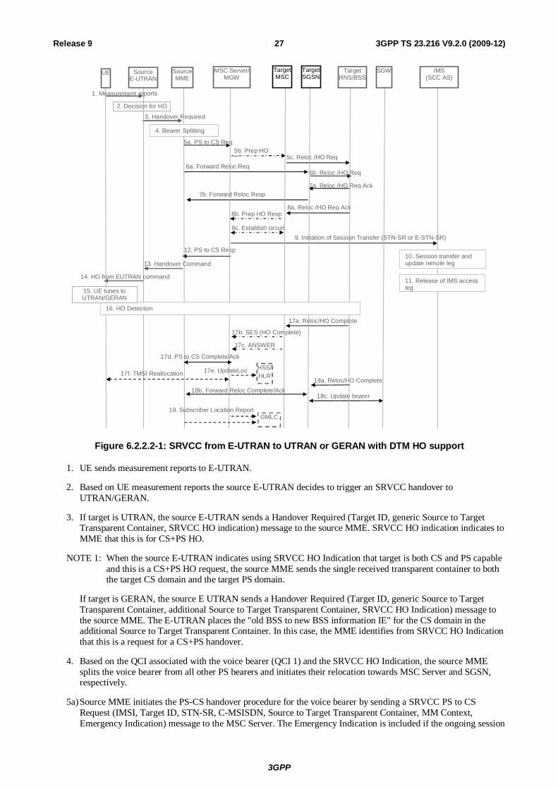
Depicted in figure 6.2.2.2-1 is a call flow for SRVCC from E-UTRAN to UTRAN or GERAN with DTM HO support, including the handling of the non-voice component.
3GPP
3GPP TS 23.216 V9.2.0 (2009-12) 27Release 9
13. Handover Command
1. Measurement reports
3. Handover Required
2. Decision for HO
5a. PS to CS Req
17a. Reloc/HO Complete
17b. SES (HO Complete)
17c. ANSWER
12. PS to CS Resp
18a. Reloc/HO Complete
18c. Update bearer
HSS/ HLR
17e. UpdateLoc
5b. Prep HO Req
8b. Prep HO Resp
8c. Establish circuit
6a. Forward Reloc Req 6b. Reloc /HO Req
5c. Reloc /HO Req
8a. Reloc /HO Req Ack
7b. Forward Reloc Resp 7a. Reloc /HO Req Ack
11. Release of IMS access leg
10. Session transfer and update remote leg
9. Initiation of Session Transfer (STN-SR or E-STN-SR)
UE Source E-UTRAN
Source MME
MSC Server/ MGW
Target MSC
Target RNS/BSS
SGW IMS (SCC AS)
TargetSGSN
14. HO from EUTRAN command
17d. PS to CS Complete/Ack
18b. Forward Reloc Complete/Ack
16. HO Detection
4. Bearer Splitting
15. UE tunes to UTRAN/GERAN
GMLC 19. Subscriber Location Report
17f. TMSI Reallocation
Figure 6.2.2.2-1: SRVCC from E-UTRAN to UTRAN or GERAN with DTM HO support
1. UE sends measurement reports to E-UTRAN.
2. Based on UE measurement reports the source E-UTRAN decides to trigger an SRVCC handover to UTRAN/GERAN.
3. If target is UTRAN, the source E-UTRAN sends a Handover Required (Target ID, generic Source to Target Transparent Container, SRVCC HO indication) message to the source MME. SRVCC HO indication indicates to MME that this is for CS+PS HO.
NOTE 1: When the source E-UTRAN indicates using SRVCC HO Indication that target is both CS and PS capable and this is a CS+PS HO request, the source MME sends the single received transparent container to both the target CS domain and the target PS domain.
If target is GERAN, the source E UTRAN sends a Handover Required (Target ID, generic Source to Target Transparent Container, additional Source to Target Transparent Container, SRVCC HO Indication) message to the source MME. The E-UTRAN places the "old BSS to new BSS information IE" for the CS domain in the additional Source to Target Transparent Container. In this case, the MME identifies from SRVCC HO Indication that this is a request for a CS+PS handover.
4. Based on the QCI associated with the voice bearer (QCI 1) and the SRVCC HO Indication, the source MME splits the voice bearer from all other PS bearers and initiates their relocation towards MSC Server and SGSN, respectively.
5a) Source MME initiates the PS-CS handover procedure for the voice bearer by sending a SRVCC PS to CS Request (IMSI, Target ID, STN-SR, C-MSISDN, Source to Target Transparent Container, MM Context, Emergency Indication) message to the MSC Server. The Emergency Indication is included if the ongoing session
3GPP
3GPP TS 23.216 V9.2.0 (2009-12) 28Release 9
is emergency session. For the case of UEs operating in Limited Service State, the MME includes the equipment identifier in this message. Authenticated IMSI and C-MSISDN shall also be included if available. The message includes information relevant to the CS domain only. MME received STN-SR and C-MSISDN from the HSS as part of the subscription profile downloaded during the E-UTRAN attach procedure. MM Context contains security related information. CS security key is derived by the MME from the E-UTRAN/EPS domain key as defined in TS 33.401 [22]. The CS Security key is sent in the MM Context.
5b) MSC Server interworks the PS-CS handover request with a CS inter-MSC handover request by sending a Prepare Handover Request message to the target MSC. If the target system is GERAN, the MSC Server assigns a default SAI as Source ID on the interface to the target BSS and uses BSSMAP encapsulated for the Prepare Handover Request. If the target system is UTRAN, the MSC Server uses RANAP encapsulated for the Prepare Handover Request.
NOTE 2: The value of the default SAI is configured in the MSC and allows a release 8 and later BSC to identify that the source for the SRVCC Handover is E-UTRAN. To ensure correct statistics in the target BSS the default SAI should be different from the SAIs used in UTRAN.
5c) Target MSC requests resource allocation for the CS relocation by sending the Relocation Request/Handover Request (additional Source to Target Transparent Container) message to the target RNS/BSS.
6. In parallel to the previous step the source MME initiates relocation of the PS bearers. The following steps are performed (for details see TS 23.401 [2] clauses 5.5.2.1 and 5.5.2.3):
a) Source MME sends a Forward Relocation Request (Source to Target Transparent Container, MM Context, PDN Connections) message to the target SGSN. The PDP Context includes bearer information for the non-voice component(s) and the voice bearer(s). The PS-to-CS handover indicator shall be set for the voice bearer(s). The handling of security keys for PS handover of the remaining non-voice PS bearers is specified in TS 33.401 [22].
NOTE 3: In case of handover to a Gn/Gp SGSN the Forward Relocation Request will contain PDP Contexts instead of PDN Connections. Also instead of providing the PS-to-CS indicator for the voice bearer(s) the MBR parameter will be set equal to zero to indicate handover to CS domain.
b) Target SGSN requests resource allocation for the PS relocation by sending the Relocation Request/Handover Request (Source to Target Transparent Container) message to the target RNS/BSS.
7. After the target RNS/BSS receives both the CS relocation/handover request with the PS relocation/handover request, it assigns the appropriate CS and PS resources. The following steps are performed:
a) Target RNS/BSS acknowledges the prepared PS relocation/handover by sending the Relocation Request Acknowledge/Handover Request Acknowledge (Target to Source Transparent Container) message to the target SGSN.
b) Target SGSN sends a Forward Relocation Response (Target to Source Transparent Container) message to the source MME.
8. In parallel to the previous step the following steps are performed:
a) Target RNS/BSS acknowledges the prepared CS relocation/handover by sending the Relocation Request Acknowledge/Handover Request Acknowledge (Target to Source Transparent Container) message to the target MSC.
b) Target MSC sends a Prepare Handover Response (Target to Source Transparent Container) message to the MSC Server.
c) Establishment of circuit connection between the target MSC and the MGW associated with the MSC Server e.g. using ISUP IAM and ACM messages.
NOTE 4: The Target to Source Transparent Container sent to the target SGSN is step 7a and the Target to Source Transparent Container sent to the target MSC in step 8a, include the same allocation of CS and PS resources (e.g. the target BSS includes the same DTM Handover Command in both containers).
9. For non-emergency session, the MSC Server initiates the Session Transfer by using the STN-SR e.g. by sending an ISUP IAM (STN-SR) message towards the IMS. For emergency session, the MSC Server initiates the Session
3GPP
3GPP TS 23.216 V9.2.0 (2009-12) 29Release 9
Transfer by using the locally configured E-STN-SR. Standard IMS Service Continuity or Emergency IMS Service Continuity procedures are applied for execution of the Session Transfer, TS 23.237 [14].
NOTE 5: This step can be started after step 8b.
NOTE 6: If the MSC Server is using an ISUP interface, then the initiation of the session transfer for non-emergency sessions may fail if the subscriber profile including CAMEL triggers is not available prior handover (see clause 7.3.2.1.3 of TS 23.292 [13]).
10. During the execution of the Session Transfer procedure the remote end is updated with the SDP of the CS access leg according to TS 23.237 [14]. The downlink flow of VoIP packets is switched towards the CS access leg at this point.
11. The source IMS access leg is released according to TS 23.237 [14].
NOTE 7: Steps 10 and 11 are independent of step 12.
12. The MSC Server sends a SRVCC PS to CS Response (Target to Source Transparent Container) message to the source MME.
13. Source MME synchronises the two prepared relocations and sends a Handover Command (Target to Source Transparent Container) message to the source E-UTRAN.
NOTE 8: When the target cell is GERAN, the MME may receive different Target to Source Transparent Containers from the MSC Server and from the SGSN, i.e. a "New BSS to Old BSS Information" (see TS 48.008 [23]) may be received from the MSC Server and a "Target BSS to Source BSS Transparent Container" (see TS 48.018 [24]) may be received from the SGSN.
14. E-UTRAN sends a Handover from E-UTRAN Command message to the UE.
15. UE tunes to the target UTRAN/GERAN cell.
16. Handover Detection at the target RNS/BSS occurs. The UE sends a Handover Complete message via the target RNS/BSS to the target MSC. If the target MSC is not the MSC Server, then the Target MSC sends an SES (Handover Complete) message to the MSC Server.
17. The CS relocation/handover is complete. The following steps are performed:
a) Target RNS/BSS sends Relocation Complete/Handover Complete message to the target MSC.
b) Target MSC sends an SES (Handover Complete) message to the MSC Server. The speech circuit is through connected in the MSC Server/MGW according to TS 23.009 [18].
c) Completion of the establishment procedure with ISUP Answer message to the MSC Server according to TS 23.009 [18].
d) MSC Server sends a SRVCC PS to CS Complete Notification message to the source MME. Source MME acknowledges the information by sending a SRVCC PS to CS Complete Acknowledge message to the MSC Server.
e) If IMSI is unknown in the VLR, the MSC Server performs a MAP Update Location to the HSS/HLR unless there is no authenticated IMSI (e.g. for an emergency services session without authenticated IMSI).
NOTE 9: This Update Location is not initiated by the UE.
f) If the MSC Server performed a MAP Update location in step 17e and if multiple MSC/VLRs serve the same LAI, the MSC Server performs a TMSI reallocation towards the UE using a non-broadcast LAI with its own Network Resource Identifier (NRI).
18. In parallel to the previous step, the PS relocation/handover is completed. The following steps are performed:
a) Target RNS/BSS sends Relocation Complete/Handover Complete message to target SGSN.
b) Target SGSN sends a Forward Relocation Complete message to the source MME. Source MME acknowledges the information by sending a Forward Relocation Complete Acknowledge message to the target SGSN.
3GPP
3GPP TS 23.216 V9.2.0 (2009-12) 30Release 9
c) Target SGSN updates the bearer with Serving GW as specified in TS 23.401 [2]. The PS-to-CS handover indicator shall be set for the voice bearer(s).
NOTE 10: For Gn/Gp SGSN the PS-to-CS indicator can not be signalled for the voice bearer(s). Instead the MBR parameter will be set equal to zero to indicate handover to CS domain.
19. For an emergency services session after handover is complete, the source MME or the MSC Server may send a Subscriber Location Report carrying the identity of the MSC Server to a GMLC associated with the source or target side, respectively, as defined in TS 23.271 [29] to support location continuity.
NOTE 11: Any configuration of the choice between a source MME versus MSC Server update to a GMLC needs to ensure that a single update occurs from one of these entities when the control plane location solution is used on the source and/or target sides.
6.3 UTRAN (HSPA) and 3GPP GERAN/UTRAN SRVCC
6.3.1 GPRS Attach procedure for SRVCC GPRS attach procedure for 3GPP SRVCC UE is performed as defined in TS 23.060 [10] with the following additions:
- SRVCC UE includes the SRVCC capability indication as part of the "MS Network Capability" in the Attach Request message and in Routeing Area Updates. SGSN stores this information for SRVCC operation.
NOTE 1: If the service configuration on the UE is changed (e.g. the user changes between an IMS speech service supported by the home operator and a PS speech service incompatible with SRVCC), the UE can change its SRVCC capability indication as part of the "MS Network Capability" in a Routeing Area Update message.
- UTRAN (HSPA) receives UE SRVCC capability indication as part of the "UE Radio Access Capability".
- SRVCC UE includes the GERAN MS Classmark 3 (if GERAN access is supported), MS Classmark 2 and Supported Codecs IE in the Attach Request message and in the non-periodic Routeing Area Update messages.
NOTE 2: MS Classmark 2, 3 and the Supported Codec IE are not sent from the source SGSN to the target MME/SGSN at inter CN-node mobility.
- If the subscriber is allowed to have SRVCC in the VPLMN then HSS includes STN-SR and C-MSISDN as part of the subscription data sent to the SGSN.
GPRS emergency attach procedure for 3GPP SRVCC UE is performed as defined in TS 23.060 [10] and above with the following clarifications:
- SRVCC UE shall include the SRVCC capability indication as part of the "MS Network Capability" in the Emergency Attach Request message and maintained during Routeing Area Updates. SGSN stores this information for SRVCC operation.
6.3.2 Call flows for SRVCC from UTRAN (HSPA) NOTE 1: If the MSC Server enhanced for SRVCC controls the target BSS/RNS, the steps depicted with dot-dashed
arrows representing the MSC-MSC handover procedure defined in TS 23.009 [18] are not executed and the functions of the MSC Server enhanced for SRVCC are merged with those of the target MSC.
NOTE 2: For the sake of brevity the call flow descriptions use "MSC Server" instead of "MSC Server enhanced for SRVCC".
NOTE 3: The target MSC need not be enhanced for SRVCC.
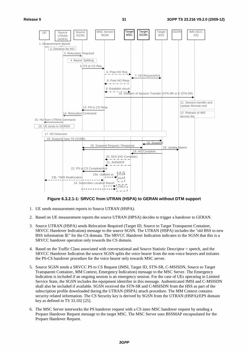
6.3.2.1 SRVCC from UTRAN (HSPA) to GERAN without DTM support
Depicted in figure 6.3.2.1-1 is a call flow for SRVCC from HSPA to GERAN without DTM support.
3GPP
3GPP TS 23.216 V9.2.0 (2009-12) 31Release 9
UE Source UTRAN (HSPA)
Source SGSN
MSC Server/ MGW
Target MSC
14. Relocation Command
Target BSS
1. Measurement reports
3. Relocation Required
GGSN
2. Decision for HO
5. PS to CS Req
6. Prep HO Req 7. HO Request/Ack
8. Prep HO Resp
9. Establish circuit
19. HO Complete
20. SES (HO Complete)
21. ANSWER
13. PS to CS Resp
15. HO from UTRAN command
4. Bearer Splitting
HSS/HLR
23a. UpdateLoc
10. Initiation of Session Transfer (STN-SR or E-STN-SR)
11. Session transfer and Update Remote end
IMS (SCC AS)
12. Release of IMS access leg
22. PS to CS Complete/Ack
Target SGSN
16. UE tunes to GERAN
17. HO Detection 18. Suspend (see TS 23.060)
18. Suspend 18. Suspend Request / Response 18. Update Bearer
GMLC 24. Subscriber Location Report
23b. TMSI Reallocation
Figure 6.3.2.1-1: SRVCC from UTRAN (HSPA) to GERAN without DTM support
1. UE sends measurement reports to Source UTRAN (HSPA).
2. Based on UE measurement reports the source UTRAN (HPSA) decides to trigger a handover to GERAN.
3. Source UTRAN (HSPA) sends Relocation Required (Target ID, Source to Target Transparent Container, SRVCC Handover Indication) message to the source SGSN. The UTRAN (HSPA) includes the "old BSS to new BSS information IE" for the CS domain. The SRVCC Handover Indication indicates to the SGSN that this is a SRVCC handover operation only towards the CS domain.
4. Based on the Traffic Class associated with conversational and Source Statistic Descriptor = speech, and the SRVCC Handover Indication the source SGSN splits the voice bearer from the non-voice bearers and initiates the PS-CS handover procedure for the voice bearer only towards MSC server.
5. Source SGSN sends a SRVCC PS to CS Request (IMSI, Target ID, STN-SR, C-MSISDN, Source to Target Transparent Container, MM Context, Emergency Indication) message to the MSC Server. The Emergency Indication is included if an ongoing session is an emergency session. For the case of UEs operating in Limited Service State, the SGSN includes the equipment identifier in this message. Authenticated IMSI and C-MSISDN shall also be included if available. SGSN received the STN-SR and C-MSISDN from the HSS as part of the subscription profile downloaded during the UTRAN (HSPA) attach procedure. The MM Context contains security related information. The CS Security key is derived by SGSN from the UTRAN (HSPA)/EPS domain key as defined in TS 33.102 [25].
6. The MSC Server interworks the PS handover request with a CS inter-MSC handover request by sending a Prepare Handover Request message to the target MSC. The MSC Server uses BSSMAP encapsulated for the Prepare Handover Request.
3GPP
3GPP TS 23.216 V9.2.0 (2009-12) 32Release 9
7. Target MSC performs resource allocation with the target BSS by exchanging Handover Request/ Acknowledge messages.
8. Target MSC sends a Prepare Handover Response message to the MSC Server.
9. Establishment of circuit connection between the target MSC and the MGW associated with the MSC Server e.g. using ISUP IAM and ACM messages.
10. For non-emergency session, the MSC Server initiates the Session Transfer by using the STN-SR e.g. by sending an ISUP IAM (STN-SR) message towards the IMS. For emergency session, the MSC Server initiates the Session Transfer by using the locally configured E-STN-SR. Standard IMS Service Continuity or Emergency IMS Service Continuity procedures are applied for execution of the Session Transfer, see TS 23.237 [14].
NOTE 1: This step can be started after step 8.
NOTE 2: If the MSC Server is using an ISUP interface, then the initiation of the session transfer for non-emergency session may fail if the subscriber profile including CAMEL triggers is not available prior handover (see clause 7.3.2.1.3 of TS 23.292 [13]).
11. During the execution of the Session Transfer procedure the remote end is updated with the SDP of the CS access leg. The downlink flow of VoIP packets is switched towards the CS access leg at this point.
12. Source IMS access leg is released according to TS 23.237 [14].
NOTE 3: Steps 11 and 12 are independent of step 13.
13. MSC Server sends a SRVCC PS to CS Response (Target to Source Transparent Container) message to the source SGSN.
14. Source SGSN sends a Relocation Command (Target to Source Transparent Container) message to the source UTRAN (HSPA). The message includes information about the voice component only.
15. Source UTRAN (HSPA) sends a Handover Command message to the UE.
16. UE tunes to GERAN.
17. Handover Detection at the target BSS occurs. The UE sends a Handover Complete message via the target RNS/BSS to the target MSC.
18. The UE starts the Suspend procedure specified in TS 23.060 [10], clause 16.2.1.1.2 and if ISR is activated the TLLI and RAI pair are derived from the GUTI as described in TS 23.401 [2]. This triggers the Target SGSN to send a Suspend Request message to the Source SGSN. The Source SGSN returns a Suspend Response to the Target SGSN. The Source SGSN also starts the preservation of non-GBR bearers and the deactivation of the voice and other GBR bearers.
19. Target BSS sends a Handover Complete message to the target MSC.
20. Target MSC sends an SES (Handover Complete) message to the MSC Server. The speech circuit is through connected in the MSC Server/MGW according to TS 23.009 [18].
21. Completion of the establishment procedure with ISUP Answer message to the MSC Server according to TS 23.009 [18].
22. MSC Server sends a SRVCC PS to CS Complete Notification message to the source SGSN, informing it that the UE has arrived on the target side. Source SGSN acknowledges the information by sending a SRVCC PS to CS Complete Acknowledge message to the MSC Server.
23a. If IMSI is unknown in the VLR, the MSC Server performs a MAP Update Location to the HSS/HLR unless there is no authenticated IMSI (e.g. for an emergency services session without authenticated IMSI).
NOTE 4: This Update Location is not initiated by the UE.
23b. If the MSC Server performed a MAP Update location in step 23a and if multiple MSC/VLRs serve the same LAI, the MSC Server performs a TMSI reallocation towards the UE using a non-broadcast LAI with its own Network Resource Identifier (NRI).
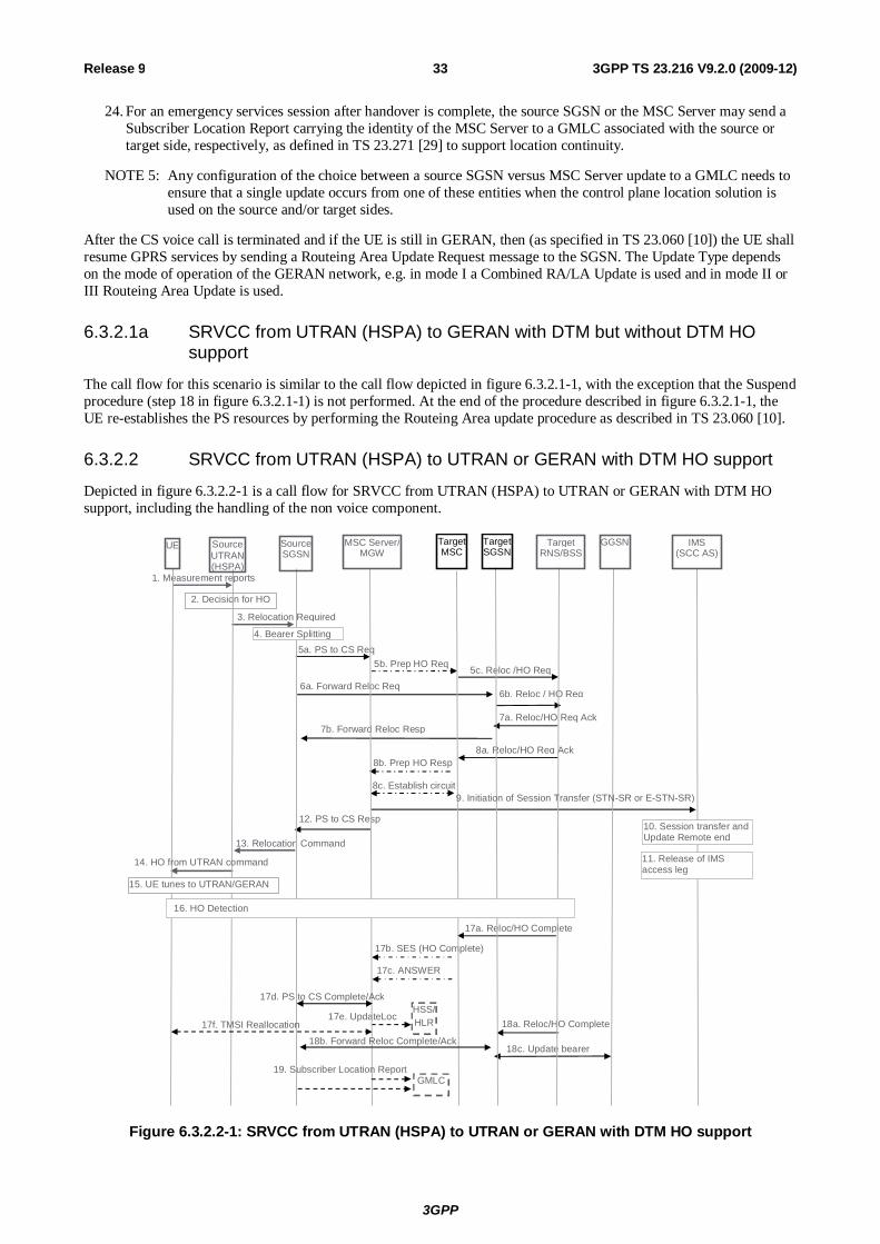
3GPP
3GPP TS 23.216 V9.2.0 (2009-12) 33Release 9
24. For an emergency services session after handover is complete, the source SGSN or the MSC Server may send a Subscriber Location Report carrying the identity of the MSC Server to a GMLC associated with the source or target side, respectively, as defined in TS 23.271 [29] to support location continuity.
NOTE 5: Any configuration of the choice between a source SGSN versus MSC Server update to a GMLC needs to ensure that a single update occurs from one of these entities when the control plane location solution is used on the source and/or target sides.
After the CS voice call is terminated and if the UE is still in GERAN, then (as specified in TS 23.060 [10]) the UE shall resume GPRS services by sending a Routeing Area Update Request message to the SGSN. The Update Type depends on the mode of operation of the GERAN network, e.g. in mode I a Combined RA/LA Update is used and in mode II or III Routeing Area Update is used.
6.3.2.1a SRVCC from UTRAN (HSPA) to GERAN with DTM but without DTM HO support
The call flow for this scenario is similar to the call flow depicted in figure 6.3.2.1-1, with the exception that the Suspend procedure (step 18 in figure 6.3.2.1-1) is not performed. At the end of the procedure described in figure 6.3.2.1-1, the UE re-establishes the PS resources by performing the Routeing Area update procedure as described in TS 23.060 [10].
6.3.2.2 SRVCC from UTRAN (HSPA) to UTRAN or GERAN with DTM HO support
Depicted in figure 6.3.2.2-1 is a call flow for SRVCC from UTRAN (HSPA) to UTRAN or GERAN with DTM HO support, including the handling of the non voice component.
13. Relocation Command
1. Measurement reports
3. Relocation Required
2. Decision for HO
5a. PS to CS Req
17a. Reloc/HO Complete
17b. SES (HO Complete)
17c. ANSWER
12. PS to CS Resp
18a. Reloc/HO Complete
18c. Update bearer
HSS/ HLR 17e. UpdateLoc
5b. Prep HO Req
8b. Prep HO Resp
8c. Establish circuit
6a. Forward Reloc Req 6b. Reloc / HO Req
5c. Reloc /HO Req
8a. Reloc/HO Req Ack
7b. Forward Reloc Resp 7a. Reloc/HO Req Ack
11. Release of IMS access leg
10. Session transfer and Update Remote end
9. Initiation of Session Transfer (STN-SR or E-STN-SR)
UE Source UTRAN (HSPA)
SourceSGSN
MSC Server/ MGW
Target MSC
Target RNS/BSS
GGSN IMS (SCC AS)
Target SGSN
14. HO from UTRAN command
17d. PS to CS Complete/Ack
18b. Forward Reloc Complete/Ack
16. HO Detection
4. Bearer Splitting
15. UE tunes to UTRAN/GERAN
GMLC 19. Subscriber Location Report
17f. TMSI Reallocation
Figure 6.3.2.2-1: SRVCC from UTRAN (HSPA) to UTRAN or GERAN with DTM HO support
3GPP
3GPP TS 23.216 V9.2.0 (2009-12) 34Release 9
1. UE sends measurement reports to Source UTRAN (HSPA).
2. Based on UE measurement reports the source UTRAN (HSPA) decides to trigger a handover to UTRAN/GERAN.
3. If target is UTRAN, the source UTRAN (HSPA) sends a Relocation Required (Target ID, Source RNC to Target RNC Transparent Container, SRVCC Handover Indication) message to the source SGSN. UTRAN (HSPA) also indicates to SGSN that this is for CS+PS HO.
NOTE 1: When the source UTRAN (HSPA) indicates that this is a CS+PS HO request, the source SGSN sends the single received transparent container to both the target CS domain and the target PS domain.
If target is GERAN, the source UTRAN (HSPA) sends a Relocation Required (Target ID, Old BSS to New BSS Information IE for the CS domain and Source BSS to Target BSS Transparent Container for the PS Domain, SRVCC Handover Indication) message to the source SGSN. In this case, the SGSN identifies from the SRVCC Handover Indication that this is a request for a CS+PS handover.
4. Based on the Traffic Class associated with conversational and Source Statistic Descriptor = speech, and the SRVCC Handover Indication the Source SGSN splits the voice bearer from all other PS bearers and initiates their relocation towards MSC Server and SGSN, respectively.
5a) Source SGSN initiates the PS-CS handover procedure for the voice bearer by sending a SRVCC PS to CS Request (IMSI, Target ID, STN-SR, C-MSISDN, Source to Target Transparent Container, MM Context, Emergency Indication) message to the MSC Server. The Emergency Indication is included if the ongoing session is emergency session. For the case of UEs operating in Limited Service Mode the SGSN includes the equipment identifier in this message. Authenticated IMSI and C-MSISDN shall be included if available. The message includes information relevant to the CS domain only. SGSN received STN-SR and C-MSISDN from the HSS as part of the subscription profile downloaded during the UTRAN (HSPA) attach procedure. MM Context contains security related information. The CS Security key is derived by the SGSN from the UTRAN (HSPA)/EPS domain key as defined in TS 33.102 [25].
5b) MSC Server interworks the PS handover request with a CS inter-MSC handover request by sending a Prepare Handover Request message to the target MSC. If the target system is GERAN, MSC Server uses BSSMAP encapsulated for the Prepare Handover Request. If the target system is UTRAN, MSC Server uses RANAP encapsulated for the Prepare Handover Request.
5c) Target MSC requests resource allocation for the CS relocation by sending the Relocation Request/Handover Request (Source to Target Transparent Container) message to the target RNS/BSS.
6. In parallel to the previous step the source SGSN initiates relocation of the PS bearers. The following steps are performed (for details see TS 23.060 [10]):
a) Source SGSN sends a Forward Relocation Request (Source to Target Transparent Container, MM Context and PDP Context) message to the target SGSN. The PDP Context includes bearer information for the non-voice component(s) and the preserved voice bearer(s) (i.e. bit rates set to 0 kbps). The handling of security keys for PS handover of the remaining non-voice PS bearers is specified in TS 33.102 [25].
b) Target SGSN requests resource allocation for the PS relocation by sending the Relocation Request/Handover Request (Source to Target Transparent Container) message to the target RNS/BSS.
7. Target RNS/BSS coordinates the CS relocation request with the PS relocation request and assigns resources. The following steps are performed:
a) Target RNS/BSS acknowledges the prepared PS relocation by sending the Relocation Request Acknowledge/Handover Request Acknowledge (Target to Source Transparent Container) message to the target SGSN.
b) Target SGSN sends a Forward Relocation Response (Target to Source Transparent Container) message to the source SGSN.
8. In parallel to the previous step the following steps are performed:
a) Target RNS/BSS acknowledges the prepared CS relocation by sending the Relocation Request Acknowledge/Handover Request Acknowledge (Target to Source Transparent Container) message to the target MSC.
3GPP
3GPP TS 23.216 V9.2.0 (2009-12) 35Release 9
b) Target MSC sends a Prepare Handover Response (Target to Source Transparent Container) message to the MSC Server.
c) Establishment of circuit connection between the target MSC and the MGW associated with the MSC Server e.g. using ISUP IAM and ACM messages.
9. For non-emergency session, the MSC Server initiates the Session Transfer by using the STN-SR e.g. by sending an ISUP IAM (STN-SR) message towards the IMS. For emergency session, the MSC Server initiates the Session Transfer by using the locally-configured E-STN-SR. Standard IMS Service Continuity or Emergency IMS Service Continuity procedures are applied for execution of the Session Transfer, see TS 23.237 [14].
NOTE 2: This step can be started after step 8b.
NOTE 3: If the MSC Server is using an ISUP interface, then the initiation of the session transfer for non-emergency sessions may fail if the subscriber profile including CAMEL triggers is not available prior handover (see clause 7.3.2.1.3 of TS 23.292 [13]).
10. During the execution of the Session Transfer procedure the remote end is updated with the SDP of the CS access leg according to TS 23.237 [14]. The downlink flow of VoIP packets is switched towards the CS access leg at this point.
11. The source IMS access leg is released according to TS 23.237 [14].
NOTE 4: Steps 10 and 11 are independent of step 12.
12. The MSC Server sends a SRVCC PS to CS Response (Target to Source Transparent Container) message to the source SGSN.
13. Source SGSN synchronises the two prepared relocations and sends a Relocation Command (Target to Source Transparent Container) message to the source UTRAN (HSPA).
14. UE tunes to the target UTRAN/GERAN cell.
15. UTRAN (HSPA) sends a Handover Command message to the UE.
16. Handover Detection at the target RNS/BSS. The UE sends a Handover Complete message via the target RNS/BSS to the target MSC.
17. The CS relocation is complete. The following steps are performed:
a) Target RNS/BSS sends Relocation Complete/Handover Complete message to the target MSC.
b) Target MSC sends an SES (Handover Complete) message to the MSC Server. The speech circuit is through connected in the MSC Server/MGW according to TS 23.009 [18].
c) Completion of the establishment procedure with ISUP Answer message to the MSC Server according to TS 23.009 [18].
d) MSC Server sends a SRVCC PS to CS Complete Notification message to the source SGSN. Source SGSN acknowledges the information by sending a SRVCC PS to CS Complete Acknowledge message to the MSC Server.
e) If IMSI is unknown in the VLR, the MSC Server performs a MAP Update Location to the HSS/HLR unless there is no authenticated IMSI (e.g. for an emergency services session without authenticated IMSI).
NOTE 5: this Update Location is not initiated by the UE.
f) If the MSC Server performed a MAP Update location in step 17e and if multiple MSC/VLRs serve the same LAI, the MSC Server performs a TMSI reallocation towards the UE using a non-broadcast LAI with its own Network Resource Identifier (NRI).
18. In parallel to the previous step, the PS relocation is complete. The following steps are performed:
a) Target RNS/BSS sends Relocation Complete/Handover Complete message to target SGSN.
3GPP
3GPP TS 23.216 V9.2.0 (2009-12) 36Release 9
b) Target SGSN sends a Forward Relocation Complete message to the source SGSN. Source SGSN acknowledges the information by sending a Forward Relocation Complete Acknowledge message to the target SGSN.
c) Target SGSN updates the bearer with GGSN.
19. For an emergency services session after handover is complete, the source SGSN or the MSC Server may send a Subscriber Location Report carrying the identity of the MSC Server to a GMLC associated with the source or target side, respectively, as defined in TS 23.271 [29] to support location continuity.
NOTE 6: Any configuration of the choice between a source SGSN versus MSC Server update to a GMLC needs to ensure that a single update occurs from one of these entities when the control plane location solution is used on the source and/or target sides.
7 Charging See TS 23.292 [13] clause 8 on charging for guidance on the handling of charging for SRVCC.
8 Handover Failure
8.1 Failure in EUTRAN/UTRAN (HSPA) and 3GPP UTRAN/GERAN SR-VCC
8.1.1 Failure before MSC Server initiates Session Transfer If a failure is encountered before the MSC Server initiates Session Transfer, then the standardised handover failure procedures apply according to TS 23.401 [2]. No further action is required by the UE.
8.1.2 Failure after UE receives HO command If the UE encounters a failure after it receives the handover command and does not successfully transition to 3GPP UTRAN/GERAN, the UE attempts to return to E-UTRAN/UTRAN, according to standardised procedures and initiates signalling to transfer the session back to E-UTRAN/UTRAN using the service continuity procedures described in TS 23.237 [14]. The core network (MME, MSC Server) shall take no SR-VCC specific action in the event of not receiving the Handover Complete message from the UE.
8.1.3 Handover Cancellation If the source E-UTRAN/UTRAN decides to terminate the handover procedure before its completion, the MME/SGSN shall return to its state before the handover procedure was triggered. The MME/SGSN attempts to trigger, at the MSC Server enhanced for SRVCC, handover cancellation procedures according to TS 23.009 [18]. The MSC Server enhanced for SRVCC shall take no SRVCC-specific action towards IMS.
The MME/SGSN shall also send a session reestablishment trigger notification to UE to start the recovery procedure if it receives notification from the MSC server that the session continuity procedure is in progress. Figure 8.1.3-1 shows the overall procedure for SRVCC handover cancellation.
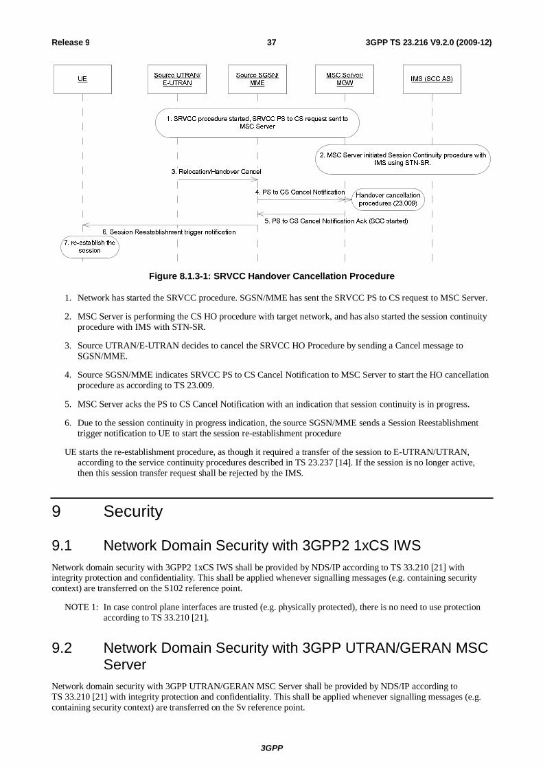
3GPP
3GPP TS 23.216 V9.2.0 (2009-12) 37Release 9
Figure 8.1.3-1: SRVCC Handover Cancellation Procedure
1. Network has started the SRVCC procedure. SGSN/MME has sent the SRVCC PS to CS request to MSC Server.
2. MSC Server is performing the CS HO procedure with target network, and has also started the session continuity procedure with IMS with STN-SR.
3. Source UTRAN/E-UTRAN decides to cancel the SRVCC HO Procedure by sending a Cancel message to SGSN/MME.
4. Source SGSN/MME indicates SRVCC PS to CS Cancel Notification to MSC Server to start the HO cancellation procedure as according to TS 23.009.
5. MSC Server acks the PS to CS Cancel Notification with an indication that session continuity is in progress.
6. Due to the session continuity in progress indication, the source SGSN/MME sends a Session Reestablishment trigger notification to UE to start the session re-establishment procedure
UE starts the re-establishment procedure, as though it required a transfer of the session to E-UTRAN/UTRAN, according to the service continuity procedures described in TS 23.237 [14]. If the session is no longer active, then this session transfer request shall be rejected by the IMS.
9 Security
9.1 Network Domain Security with 3GPP2 1xCS IWS Network domain security with 3GPP2 1xCS IWS shall be provided by NDS/IP according to TS 33.210 [21] with integrity protection and confidentiality. This shall be applied whenever signalling messages (e.g. containing security context) are transferred on the S102 reference point.
NOTE 1: In case control plane interfaces are trusted (e.g. physically protected), there is no need to use protection according to TS 33.210 [21].
9.2 Network Domain Security with 3GPP UTRAN/GERAN MSC Server
Network domain security with 3GPP UTRAN/GERAN MSC Server shall be provided by NDS/IP according to TS 33.210 [21] with integrity protection and confidentiality. This shall be applied whenever signalling messages (e.g. containing security context) are transferred on the Sv reference point.
3GPP
3GPP TS 23.216 V9.2.0 (2009-12) 38Release 9
NOTE 2: In case control plane interfaces are trusted (e.g. physically protected), there is no need to use protection according to TS 33.210 [21].
3GPP
3GPP TS 23.216 V9.2.0 (2009-12) 39Release 9
Annex A (informative): Determination of Neighbour Cell List This annex describes example algorithms for determination of Neighbour Cell List (NCL) for SRVCC operation. In case of SRVCC to GERAN/UTRAN it is also clarified when the E-UTRAN includes a SRVCC indication in the Handover Required message.
A.1 SRVCC from E-UTRAN to 3GPP2 1xCS E-UTRAN may determine the NCL as follows:
- If the "SRVCC operation possible" indication is set to "true" (i.e. both EPC and UE are SRVCC capable), then:
- if there is an established QCI=1 bearer for this UE, then 1x cells may be included as candidate target cells in the NCL;
- if there is no established QCI=1 bearer for this UE, then 1x cells are not included in the NCL.
- If the "SRVCC operation possible" indication is set to "false" (i.e. either EPC or UE is not SRVCC capable), then 1x cells are not included in the NCL.
A.2 SRVCC from E-UTRAN to GERAN/UTRAN E-UTRAN may determine the NCL, as well as the need to signal a SRVCC indication, as follows:
- If the "SRVCC operation possible" indication is set to "true" (i.e. both EPC and UE are SRVCC capable), then VoIP-incapable cells may be included as candidate target cells in the NCL, regardless of the presence of established QCI=1 bearers for this UE. Moreover:
- if there is an established QCI=1 bearer for this UE and the selected target cell is VoIP-capable, then E-UTRAN does not include a SRVCC indication in the Handover Required message;
- if there is an established QCI=1 bearer for this UE and the selected target cell is VoIP-incapable, then E-UTRAN includes a SRVCC indication in the Handover Required message;
- if there is no established QCI=1 bearer for this UE, then E-UTRAN does not include a SRVCC indication in the Handover Required message;
- If the "SRVCC operation possible" indication is set to "false" (i.e. either EPC or UE is not SRVCC capable), then E-UTRAN does not include a SRVCC indication in the Handover Required message. Moreover:
- if there is an established QCI=1 bearer for this UE, then VoIP-incapable cell are not be included in the NCL;
- if there is no established QCI=1 bearer for this UE, then VoIP-incapable cells may be included in the NCL.
A.3 SRVCC from UTRAN (HSPA) to GERAN/UTRAN Similar logic may be used as in clause A.2 by replacing E-UTRAN with UTRAN.
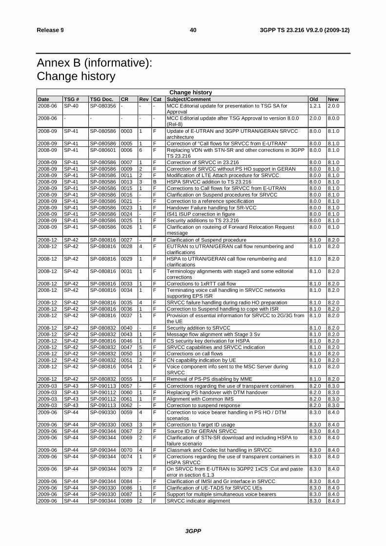
3GPP
3GPP TS 23.216 V9.2.0 (2009-12) 40Release 9
Annex B (informative): Change history
Change history Date TSG # TSG Doc. CR Rev Cat Subject/Comment Old New 2008-06 SP-40 SP-080356 - - - MCC Editorial update for presentation to TSG SA for
Approval 1.2.1 2.0.0
2008-06 - - - - - MCC Editorial update after TSG Approval to version 8.0.0 (Rel-8)
2.0.0 8.0.0
2008-09 SP-41 SP-080586 0003 1 F Update of E-UTRAN and 3GPP UTRAN/GERAN SRVCC architecture
8.0.0 8.1.0
2008-09 SP-41 SP-080586 0005 1 F Correction of "Call flows for SRVCC from E-UTRAN" 8.0.0 8.1.0 2008-09 SP-41 SP-080601 0006 6 F Replacing VDN with STN-SR and other corrections in 3GPP
TS 23.216 8.0.0 8.1.0
2008-09 SP-41 SP-080586 0007 1 F Correction of SRVCC in 23.216 8.0.0 8.1.0 2008-09 SP-41 SP-080586 0009 2 F Correction of SRVCC without PS HO support in GERAN 8.0.0 8.1.0 2008-09 SP-41 SP-080586 0011 2 F Modification of LTE Attach procedure for SRVCC 8.0.0 8.1.0 2008-09 SP-41 SP-080586 0013 3 B HSPA SRVCC addition to TS 23.216 8.0.0 8.1.0 2008-09 SP-41 SP-080586 0015 1 F Corrections to Call flows for SRVCC from E-UTRAN 8.0.0 8.1.0 2008-09 SP-41 SP-080586 0016 - F Clarification on Suspend procedures for SRVCC 8.0.0 8.1.0 2008-09 SP-41 SP-080586 0021 - F Correction to a reference specification 8.0.0 8.1.0 2008-09 SP-41 SP-080586 0023 1 F Handover Failure handling for SR-VCC 8.0.0 8.1.0 2008-09 SP-41 SP-080586 0024 - F IS41 ISUP correction in figure 8.0.0 8.1.0 2008-09 SP-41 SP-080586 0025 1 F Security additions to TS 23.216 8.0.0 8.1.0 2008-09 SP-41 SP-080586 0026 1 F Clarification on routeing of Forward Relocation Request
message 8.0.0 8.1.0
2008-12 SP-42 SP-080816 0027 - F Clarification of Suspend procedure 8.1.0 8.2.0 2008-12 SP-42 SP-080816 0028 4 F EUTRAN to UTRAN/GERAN call flow renumbering and
clarifications 8.1.0 8.2.0
2008-12 SP-42 SP-080816 0029 1 F HSPA to UTRAN/GERAN call flow renumbering and clarifications
8.1.0 8.2.0
2008-12 SP-42 SP-080816 0031 1 F Terminology alignments with stage3 and some editorial corrections
8.1.0 8.2.0
2008-12 SP-42 SP-080816 0033 1 F Corrections to 1xRTT call flow 8.1.0 8.2.0 2008-12 SP-42 SP-080816 0034 1 F Terminating voice call handling in SRVCC networks
supporting EPS ISR 8.1.0 8.2.0
2008-12 SP-42 SP-080816 0035 4 F SRVCC failure handling during radio HO preparation 8.1.0 8.2.0 2008-12 SP-42 SP-080816 0036 1 F Correction to Suspend handling to cope with ISR 8.1.0 8.2.0 2008-12 SP-42 SP-080816 0037 1 F Provision of essential information for SRVCC to 2G/3G from
the UE 8.1.0 8.2.0
2008-12 SP-42 SP-080832 0040 - F Security addition to SRVCC 8.1.0 8.2.0 2008-12 SP-42 SP-080832 0043 1 F Message flow alignment with Stage 3 Sv 8.1.0 8.2.0 2008-12 SP-42 SP-080816 0046 1 F CS security key derivation for HSPA 8.1.0 8.2.0 2008-12 SP-42 SP-080832 0047 5 F SRVCC capabilities and SRVCC indication 8.1.0 8.2.0 2008-12 SP-42 SP-080832 0050 1 F Corrections on call flows 8.1.0 8.2.0 2008-12 SP-42 SP-080832 0051 2 F CN capability indication by UE 8.1.0 8.2.0 2008-12 SP-42 SP-080816 0054 1 F Voice component info sent to the MSC Server during
SRVCC 8.1.0 8.2.0
2008-12 SP-42 SP-080832 0055 1 F Removal of PS-PS disabling by MME 8.1.0 8.2.0 2009-03 SP-43 SP-090113 0057 - F Corrections regarding the use of transparent containers 8.2.0 8.3.0 2009-03 SP-43 SP-090112 0060 1 F Replacing PS handover with DTM handover 8.2.0 8.3.0 2009-03 SP-43 SP-090112 0061 1 F Alignment with Common IMS 8.2.0 8.3.0 2009-03 SP-43 SP-090113 0062 - F Correction to suspend response 8.2.0 8.3.0 2009-06 SP-44 SP-090330 0059 4 F Correction to voice bearer handling in PS HO / DTM
scenarios 8.3.0 8.4.0
2009-06 SP-44 SP-090330 0063 3 F Correction to Target ID usage 8.3.0 8.4.0 2009-06 SP-44 SP-090344 0067 2 F Source ID for GERAN SRVCC 8.3.0 8.4.0 2009-06 SP-44 SP-090344 0069 2 F Clarification of STN-SR download and including HSPA to
failure scenario 8.3.0 8.4.0
2009-06 SP-44 SP-090344 0070 4 F Classmark and Codec list handling in SRVCC 8.3.0 8.4.0 2009-06 SP-44 SP-090344 0074 1 F Corrections regarding the use of transparent containers in
HSPA SRVCC 8.3.0 8.4.0
2009-06 SP-44 SP-090344 0079 2 F On SRVCC from E-UTRAN to 3GPP2 1xCS :Cut and paste error in section 6.1.3
8.3.0 8.4.0
2009-06 SP-44 SP-090344 0084 - F Clarification of IMSI and Gr interface in SRVCC 8.3.0 8.4.0 2009-06 SP-44 SP-090330 0086 1 F Clarification of UE-TADS for SRVCC UEs 8.3.0 8.4.0 2009-06 SP-44 SP-090330 0087 1 F Support for multiple simultaneous voice bearers 8.3.0 8.4.0 2009-06 SP-44 SP-090344 0089 2 F SRVCC indicator alignment 8.3.0 8.4.0
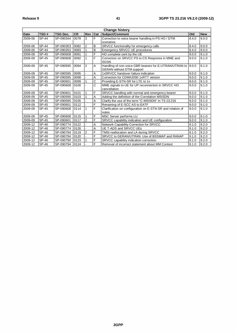
3GPP
3GPP TS 23.216 V9.2.0 (2009-12) 41Release 9
Change history Date TSG # TSG Doc. CR Rev Cat Subject/Comment Old New 2009-06 SP-44 SP-090344 0078 3 F Correction to voice bearer handling in PS HO / DTM
scenarios 8.4.0 9.0.0
2009-06 SP-44 SP-090353 0082 2 B SRVCC functionality for emergency calls 8.4.0 9.0.0 2009-06 SP-44 SP-090353 0083 1 B Emergency SRVCC UE procedures 8.4.0 9.0.0 2009-09 SP-45 SP-090608 0091 1 F HO complete sent by the UE 9.0.0 9.1.0 2009-09 SP-45 SP-090608 0092 1 F Correction on SRVCC PS to CS Response in MME and
SGSN 9.0.0 9.1.0
2009-09 SP-45 SP-090595 0094 2 A Handling of non-voice GBR bearers for E-UTRAN/UTRAN to GERAN without DTM support
9.0.0 9.1.0
2009-09 SP-45 SP-090595 0095 - A 1xSRVCC handover failure indication 9.0.0 9.1.0 2009-09 SP-45 SP-090595 0098 - A Correction for CDMA2000 1xRTT version 9.0.0 9.1.0 2009-09 SP-45 SP-090601 0099 1 C Providing E-STN-SR for LTE to 1x 9.0.0 9.1.0 2009-09 SP-45 SP-090608 0100 - C MME signals to UE for UP reconnection in SRVCC HO
cancellation 9.0.0 9.1.0
2009-09 SP-45 SP-090601 0101 1 F SRVCC handling with normal and emergency bearer 9.0.0 9.1.0 2009-09 SP-45 SP-090595 0103 1 A Adding the definition of the Correlation MSISDN 9.0.0 9.1.0 2009-09 SP-45 SP-090595 0105 - A Clarify the use of the term "C-MSISDN" in TS 23.216 9.0.0 9.1.0 2009-09 SP-45 SP-090601 0112 - F Renaming of E-SCC AS to EATF 9.0.0 9.1.0 2009-09 SP-45 SP-090608 0114 1 F Clarification on configuration on E-STN-SR and relation of
notes 9.0.0 9.1.0
2009-09 SP-45 SP-090608 0115 1 F MSC Server performs LU 9.0.0 9.1.0 2009-09 SP-45 SP-090601 0117 2 F SRVCC capability indication and UE configuration 9.0.0 9.1.0 2009-12 SP-46 SP-090774 0122 - A Network Capability Correction for SRVCC 9.1.0 9.2.0 2009-12 SP-46 SP-090774 0126 - A UE T-ADS and SRVCC UEs 9.1.0 9.2.0 2009-12 SP-46 SP-090794 0119 2 F TMSI reallocation and LA during SRVCC 9.1.0 9.2.0 2009-12 SP-46 SP-090794 0120 - F SRVCC to GERAN/UTRAN: Use of BSSMAP and RANAP 9.1.0 9.2.0 2009-12 SP-46 SP-090790 0123 1 F SRVCC capability indication correction 9.1.0 9.2.0 2009-12 SP-46 SP-090794 0124 - F Removal of incorrect statement about MM Context 9.1.0 9.2.0