3gpp ts 29 - etsi.org · 3gpp ts 29.214 version 7.4.0 release 7 etsi 1 etsi ts 129 214 v7.4.0...
TRANSCRIPT

ETSI TS 129 214 V7.4.0 (2008-04)
Technical Specification
Universal Mobile Telecommunications System (UMTS);Policy and charging control over Rx reference point
(3GPP TS 29.214 version 7.4.0 Release 7)

ETSI
ETSI TS 129 214 V7.4.0 (2008-04) 1 3GPP TS 29.214 version 7.4.0 Release 7
Reference RTS/TSGC-0329214v740
Keywords UMTS
ETSI
650 Route des Lucioles F-06921 Sophia Antipolis Cedex - FRANCE
Tel.: +33 4 92 94 42 00 Fax: +33 4 93 65 47 16
Siret N° 348 623 562 00017 - NAF 742 C
Association à but non lucratif enregistrée à la Sous-Préfecture de Grasse (06) N° 7803/88
Important notice
Individual copies of the present document can be downloaded from: http://www.etsi.org
The present document may be made available in more than one electronic version or in print. In any case of existing or perceived difference in contents between such versions, the reference version is the Portable Document Format (PDF).
In case of dispute, the reference shall be the printing on ETSI printers of the PDF version kept on a specific network drive within ETSI Secretariat.
Users of the present document should be aware that the document may be subject to revision or change of status. Information on the current status of this and other ETSI documents is available at
http://portal.etsi.org/tb/status/status.asp
If you find errors in the present document, please send your comment to one of the following services: http://portal.etsi.org/chaircor/ETSI_support.asp
Copyright Notification
No part may be reproduced except as authorized by written permission. The copyright and the foregoing restriction extend to reproduction in all media.
© European Telecommunications Standards Institute 2008.
All rights reserved.
DECTTM, PLUGTESTSTM, UMTSTM, TIPHONTM, the TIPHON logo and the ETSI logo are Trade Marks of ETSI registered for the benefit of its Members.
3GPPTM is a Trade Mark of ETSI registered for the benefit of its Members and of the 3GPP Organizational Partners.
ETSI
ETSI TS 129 214 V7.4.0 (2008-04) 2 3GPP TS 29.214 version 7.4.0 Release 7
Intellectual Property Rights IPRs essential or potentially essential to the present document may have been declared to ETSI. The information pertaining to these essential IPRs, if any, is publicly available for ETSI members and non-members, and can be found in ETSI SR 000 314: "Intellectual Property Rights (IPRs); Essential, or potentially Essential, IPRs notified to ETSI in respect of ETSI standards", which is available from the ETSI Secretariat. Latest updates are available on the ETSI Web server (http://webapp.etsi.org/IPR/home.asp).
Pursuant to the ETSI IPR Policy, no investigation, including IPR searches, has been carried out by ETSI. No guarantee can be given as to the existence of other IPRs not referenced in ETSI SR 000 314 (or the updates on the ETSI Web server) which are, or may be, or may become, essential to the present document.
Foreword This Technical Specification (TS) has been produced by ETSI 3rd Generation Partnership Project (3GPP).
The present document may refer to technical specifications or reports using their 3GPP identities, UMTS identities or GSM identities. These should be interpreted as being references to the corresponding ETSI deliverables.
The cross reference between GSM, UMTS, 3GPP and ETSI identities can be found under http://webapp.etsi.org/key/queryform.asp.
ETSI
ETSI TS 129 214 V7.4.0 (2008-04) 3 3GPP TS 29.214 version 7.4.0 Release 7
Contents
Intellectual Property Rights ................................................................................................................................2
Foreword.............................................................................................................................................................2
Foreword.............................................................................................................................................................5
1 Scope ........................................................................................................................................................6
2 References ................................................................................................................................................6
3 Definitions and abbreviations...................................................................................................................7 3.1 Definitions..........................................................................................................................................................7 3.2 Abbreviations .....................................................................................................................................................7
4 Rx reference point ....................................................................................................................................8 4.1 Overview ............................................................................................................................................................8 4.2 Rx reference model ............................................................................................................................................8 4.3 Functional elements............................................................................................................................................9 4.3.1 AF .................................................................................................................................................................9 4.3.2 PCRF ............................................................................................................................................................9 4.4 PCC procedures over Rx reference point .........................................................................................................10 4.4.1 Initial Provisioning of Session Information ................................................................................................10 4.4.2 Modification of Session Information ..........................................................................................................11 4.4.3 Gate Related Procedures.............................................................................................................................12 4.4.4 AF Session Termination .............................................................................................................................12 4.4.5 Subscription to Notification of Signalling Path Status ...............................................................................12 4.4.5a Subscription to IP-CAN type change Notification......................................................................................13 4.4.6 Traffic Plane Events....................................................................................................................................13 4.4.6.1 IP-CAN Session Termination................................................................................................................13 4.4.6.2 Service Data Flow Deactivation............................................................................................................13 4.4.6.3 Notification of Signalling Path Status ...................................................................................................14 4.4.6.4 IP-CAN type change Notification .........................................................................................................14 4.4.6.5 Access Network Charging Information Notification.............................................................................14
5 Rx protocol.............................................................................................................................................14 5.1 Protocol support ...............................................................................................................................................14 5.2 Initialization, maintenance and termination of connection and session............................................................15 5.3 Rx specific AVPs .............................................................................................................................................15 5.3.1 Abort-Cause AVP.......................................................................................................................................16 5.3.2 Access-Network-Charging-Address AVP ..................................................................................................16 5.3.3 Access-Network-Charging-Identifier AVP.................................................................................................17 5.3.4 Access-Network-Charging-Identifier-Value AVP......................................................................................17 5.3.5 AF-Application-Identifier AVP..................................................................................................................17 5.3.6 AF-Charging-Identifier AVP ......................................................................................................................17 5.3.7 Codec-Data AVP ........................................................................................................................................17 5.3.8 Flow-Description AVP ...............................................................................................................................18 5.3.9 Flow-Number AVP.....................................................................................................................................18 5.3.10 Flows AVP..................................................................................................................................................18 5.3.11 Flow-Status AVP ........................................................................................................................................19 5.3.12 Flow-Usage AVP........................................................................................................................................19 5.3.13 Specific-Action AVP ..................................................................................................................................19 5.3.14 Max-Requested-Bandwidth-DL AVP.........................................................................................................20 5.3.15 Max-Requested-Bandwidth-UL AVP.........................................................................................................21 5.3.16 Media-Component-Description AVP .........................................................................................................21 5.3.17 Media-Component-Number AVP...............................................................................................................22 5.3.18 Media-Sub-Component AVP......................................................................................................................22 5.3.19 Media-Type AVP........................................................................................................................................22 5.3.20 RR-Bandwidth AVP ...................................................................................................................................23 5.3.21 RS-Bandwidth AVP....................................................................................................................................23 5.3.22 SIP-Forking-Indication AVP ......................................................................................................................23

ETSI
ETSI TS 129 214 V7.4.0 (2008-04) 4 3GPP TS 29.214 version 7.4.0 Release 7
5.3.23 Service-URN AVP......................................................................................................................................23 5.3.24 Acceptable-Service-Info AVP ....................................................................................................................23 5.3.25 Service-Info-Status-AVP ............................................................................................................................24 5.4 Rx re-used AVPs..............................................................................................................................................24 5.5 Rx specific Experimental-Result-Code AVP values ........................................................................................25 5.6 Rx messages .....................................................................................................................................................25 5.6.1 AA-Request (AAR) command....................................................................................................................25 5.6.2 AA-Answer (AAA) command....................................................................................................................26 5.6.3 Re-Auth-Request (RAR) command ............................................................................................................26 5.6.4 Re-Auth-Answer (RAA) command ............................................................................................................27 5.6.5 Session-Termination-Request (STR) command .........................................................................................27 5.6.6 Session-Termination-Answer (STA) command..........................................................................................27 5.6.7 Abort-Session-Request (ASR) command ...................................................................................................28 5.6.8 Abort-Session-Answer (ASA) command....................................................................................................28
Annex A (normative): IMS Related P-CSCF Procedures over Rx..................................................29
A.1 Provision of Service Information at P-CSCF .........................................................................................29
A.2 Enabling of IP Flows..............................................................................................................................30
A.3 Support for SIP forking ..........................................................................................................................30 A.3.1 PCC rule provisioning for early media for forked responses ...........................................................................30 A.3.2 Updating the provisioned PCC rules at the final answer ..................................................................................31
A.4 Notification of IMS Signalling Transmission Path Status .....................................................................31
A.5 Indication of Emergency Session ...........................................................................................................31
Annex B (normative): Flow identifiers: Format definition and examples ......................................32
B.1 Format of a flow identifier .....................................................................................................................32
B.2 Example 1...............................................................................................................................................33
B.3 Example 2...............................................................................................................................................34
B.4 Example 3 without media components...................................................................................................35
B.5 Example 4...............................................................................................................................................36
Annex C (informative): Change history ...............................................................................................37
History ..............................................................................................................................................................38
ETSI
ETSI TS 129 214 V7.4.0 (2008-04) 5 3GPP TS 29.214 version 7.4.0 Release 7
Foreword This Technical Specification has been produced by the 3rd Generation Partnership Project (3GPP).
The contents of the present document are subject to continuing work within the TSG and may change following formal TSG approval. Should the TSG modify the contents of the present document, it will be re-released by the TSG with an identifying change of release date and an increase in version number as follows:
Version x.y.z
where:
x the first digit:
1 presented to TSG for information;
2 presented to TSG for approval;
3 or greater indicates TSG approved document under change control.
y the second digit is incremented for all changes of substance, i.e. technical enhancements, corrections, updates, etc.
z the third digit is incremented when editorial only changes have been incorporated in the document.
ETSI
ETSI TS 129 214 V7.4.0 (2008-04) 6 3GPP TS 29.214 version 7.4.0 Release 7
1 Scope The present document provides the stage 3 specification of the Rx reference point for the present release. The functional requirements and the stage 2 specifications of the Rx reference point are contained in 3GPP TS 23.203 [7]. The Rx reference point lies between the Application Function and the Policy and Charging Rule Function.
Whenever it is possible the present document specifies the requirements for the protocol by reference to specifications produced by the IETF within the scope of Diameter. Where this is not possible, extensions to Diameter are defined within the present document.
2 References The following documents contain provisions which, through reference in this text, constitute provisions of the present document.
• References are either specific (identified by date of publication and/or edition number or version number) or non-specific.
• For a specific reference, subsequent revisions do not apply.
• For a non-specific reference, the latest version applies. In the case of a reference to a 3GPP document (including a GSM document), a non-specific reference implicitly refers to the latest version of that document in the same Release as the present document.
[1] 3GPP TR 21.905: "Vocabulary for 3GPP Specifications".
[2] 3GPP TS 23.203: "Policy and Charging Control architecture".
[3] void
[4] void
[5] 3GPP TS 29.209: "Policy control over Gq interface", latest Rel-6 version.
[6] void
[7] 3GPP TS 29.211: "Rx Interface and Rx/Gx signalling flows", latest Rel-6 version.
[8] 3GPP TS 29.212: "Policy and Charging Control over Gx reference point".
[9] 3GPP TS 29.213: "Policy and Charging Control signalling flows and QoS parameter mapping".
[10] IETF RFC 3588: "Diameter Base Protocol".
[11] IETF RFC 3556: "Session Description Protocol (SDP) Bandwidth Modifiers for RTP Control Protocol (RTCP) Bandwidth".
[12] IETF RFC 4005: "Diameter Network Access Server Application".
[13] IETF RFC 4566: "SDP: Session Description Protocol".
[14] IETF RFC 4006: "Diameter Credit Control Application".
[15] ETSI TS 183 017: "Telecommunications and Internet Converged Services and Protocols for Advanced Networking (TISPAN); Resource and Admission Control: DIAMETER protocol for session based policy set-up information exchange between the Application Function (AF) and the Service Policy Decision Function (SPDF); Protocol specification".
[16] 3GPP TS 23.228: "IP Multimedia Subsystem (IMS); Stage 2".
[17] 3GPP TS 24.229: "IP Multimedia Call Control Protocol based on SIP and SDP; Stage 3".

ETSI
ETSI TS 129 214 V7.4.0 (2008-04) 7 3GPP TS 29.214 version 7.4.0 Release 7
[18] IETF RFC 3264: "An Offer/Answer Model with the Session Description Protocol (SDP)".
[19] IETF RFC 4566: "SDP: Session Description Protocol".
[20] IETF RFC 3162: "Radius and IPv6".
[21] draft-ietf-ecrit-service-urn-05 (August 2006): "A Uniform Resource Name (URN) for Services".
Editor's note: The above document cannot be formally referenced until it is published as an RFC.
[22] 3GPP TS 29.061: "Interworking between the Public Land Mobile Network (PLMN) supporting packet based services and Packet Data Networks (PDN)".
3 Definitions and abbreviations
3.1 Definitions For the purposes of the present document, the terms and definitions given in 3GPP TR 21.905 [1] and the following apply:
Application Function (AF): element offering application(s) that use IP bearer resources
NOTE: One example of an AF is the P-CSCF of the IM CN subsystem.
AF Session: application level session established by an application level signalling protocol offered by the AF that requires a session set-up with explicit session description before the use of the service.
NOTE: One example of an application session is an IMS session.
Attribute-Value Pair (AVP): See RFC 3588 [5], corresponds to an Information Element in a Diameter message.
binding: PCRF process of associating IP flows described in AF Service Information with IP-CAN bearers.
IP-CAN bearer: IP transmission path of defined capacity, delay and bit error rate, etc. See 3GPP TS 21.905 [1] for the definition of bearer.
IP-CAN session: association between a UE and an IP network (for GPRS, APN). The association is identified by a UE IP address together with a UE identity information, if available. An IP-CAN session incorporates one or more IP-CAN bearers. Support for multiple IP-CAN bearers per IP-CAN session is IP-CAN specific. An IP-CAN session exists as long as the UE IP address is established and announced to the IP network.
IP flow: unidirectional flow of IP packets with the same source IP address and port number and the same destination IP address and port number and the same transport protocol Port numbers are only applicable if used by the transport protocol.
packet flow: A specific user data flow carried through the PCEF. A packet flow can be an IP flow.
PCC rule: set of information enabling the detection of a service data flow and providing parameters for policy control and/or charging control
service information: set of information conveyed from the AF to the PCRF over the Rx interface to be used as a basis for PCC decisions at the PCRF, including information about the AF session (e.g. application identifier, type of media, bandwidth, IP address and port number)
service data flow: An aggregate set of packet flows.
3.2 Abbreviations For the purpose of the present document, the abbreviations given in 3GPP TR 21.905 [1] and the following apply:
AF Application Function

ETSI
ETSI TS 129 214 V7.4.0 (2008-04) 8 3GPP TS 29.214 version 7.4.0 Release 7
AVP Attribute Value Pair CRF Charging Rules Function IP-CAN IP Connectivity Access Network PCC Policy and Charging Control PCEF Policy and Charging Enforcement Function PCRF Policy and Charging Rule Function PDF Policy Decision Function P-CSCF Proxy-Call Session Control Function QoS Quality of Service SDF Service Data Flow SPR Subscriber Profile Repository UE User Equipment
4 Rx reference point
4.1 Overview The Rx reference point is used to exchange application level session information between the Policy and Charging Rules Function (PCRF) and the Application Function (AF). As defined in the stage 2 specifications (3GPP TS 23.203 [2]), this information is part of the input used by the PCRF for the Policy and Charging Control (PCC) decisions. The PCRF exchanges the PCC rules with the Policy and Charging Enforcement Function (PCEF) as specified in 3GPP TS 29.212 [8].
Signalling flows related to the both Rx and Gx interfaces are specified in 3GPP TS 29.213 [9].
4.2 Rx reference model The Rx reference point is defined between the PCRF and the AF. The relationships between the different functional entities involved are depicted in figure 4.1.

ETSI
ETSI TS 129 214 V7.4.0 (2008-04) 9 3GPP TS 29.214 version 7.4.0 Release 7
GW
Online Charging System (OCS)
Service Data Flow
Based Credit Control
Policy and Charging
Rules Function (PCRF)
CAMELSCP
Gy
Rx
AF
Gz
Gx
Subscription Profile
Repository (SPR)
Sp
Offline Charging System (OFCS)
PCEF
Figure 4.1: Rx reference point at the Policy and Charging Control (PCC) architecture
NOTE: The details associated with the Sp reference point are not specified in this Release. The SPR's relation to existing subscriber databases is not specified in this Release.
4.3 Functional elements
4.3.1 AF
The AF is an element offering applications that require the Policy and Charging Control of traffic plane resources (e.g. UMTS PS domain/GPRS domain resources). One example of an application function is the P-CSCF. The AF shall use the Rx reference point to provide session information to the PCRF.
4.3.2 PCRF
The PCRF (Policy Control and Charging Rules Function) is a functional element that encompasses policy control decision and flow based charging control functionalities. These 2 functionalities are the heritage of the release 6 logical entities PDF and CRF respectively. The PCRF provides network control regarding the service data flow detection, gating, QoS and flow based charging (except credit management) towards the PCEF. The PCRF receives session and media related information from the AF and informs AF of traffic plane events.
The PCRF may check that the service information provided by the AF is consistent with the operator defined policy rules before storing the service information. The service information shall be used to derive the QoS for the service. The PCRF may reject the request received from the AF and as a result the PCRF shall indicate, in the response to the AF, the service information that can be accepted by the PCRF.

ETSI
ETSI TS 129 214 V7.4.0 (2008-04) 103GPP TS 29.214 version 7.4.0 Release 7
The PCRF may use the subscription information as basis for the policy and charging control decisions. The subscription information may apply for both session based and non-session based services. The subscription specific information for each service may contain e.g. max QoS class and max bit rate.
If the AF requests it, the PCRF shall report IP-CAN session events (including bearer events and events on AF signalling transport) to the AF via the Rx reference point.
The PCRF PCC Rule decisions may be based on one or more of the following:
- the session and media related information obtained from the AF via the Rx reference point;
- the bearer and subscriber related information obtained from the PCEF over the Gx reference point;
- subscriber and service related data the PCRF may be aware of by configuration or through the Sp reference point;
- pre-configured information in the PCRF.
NOTE: The details associated with the Sp reference point are not specified in this Release. The SPR's relation to existing subscriber databases is not specified in this Release.
The PCRF shall provision PCC Rules to the PCEF via the Gx reference point.
4.4 PCC procedures over Rx reference point
4.4.1 Initial Provisioning of Session Information
When a new AF session is being established and media information for this AF session is available at the AF, the AF shall open an Rx Diameter session with the PCRF using a AA-Request command. The AF shall provide the UE's IP address using either Framed-IP-Address AVP or Framed-IPv6-Prefix AVP, and the corresponding Service Information within Media-Component-Description AVP(s). The AF shall indicate to the PCRF as part of the Media-Component-Description whether the media IP flow(s) should be enabled or disabled with the Flow-Status AVP.
The AF may include the AF-Application-Identifier AVP into the AA-Request in order to indicate the particular service that the AF session belongs to. This AVP can be provided at both AF session level, and Media-Component-Description level. When provided at both levels, the AF-Application Identifier provided within the Media-Component-Description AVP will have precedence.
The AF may include the AF-Charging-Identifier AVP into the AA-Request for charging correlation purposes. The AF may also include the Specific-Action AVP to request notification for certain user plane events, e.g. bearer termination.
The AF may include the Service-URN AVP in order to indicate that the new AF session relates to emergency traffic. If the PCRF receives the Service-URN AVP indicating an emergency session, the PCRF may apply special policies, for instance prioritising service flows relating to the new AF session or allowing these service flows free of charge.
For the normal case that the AF provides service information that has been fully negotiated (e.g. based on the SDP answer), the AF may include the Service-Info-Status AVP set to FINAL_SERVICE_INFORMATION. In this case the PCRF shall authorize the session and provision the corresponding PCC rules to the PCEF.
The AF may additionally provide preliminary service information not fully negotiated yet (e.g. based on the SDP offer) at an earlier stage. To do so, the AF shall include the Service-Info-Status AVP with the value set to PRELIMINARY SERVICE INFORMATION. Upon receipt of such preliminary service information, the PCRF shall perform an early authorization check of the service information. For GPRS, the PCRF shall not provision PCC rules towards the PCEF.
When the PCRF receives an initial AA-Request from the AF, the PCRF shall perform session binding as described in 3GPP TS 29.213 [9]. To allow the PCRF to identify the IP-CAN session for which this request applies, the AF shall provide either the Framed-IP-Address or the Framed-IPv6-Prefix containing the routable IP address applicable for the IP Flows towards the UE. If the PCRF fails in executing session binding, the PCRF responds to the AF with an AA-Answer including the Experimental-Result-Code AVP set to the value IP-CAN_SESSION_NOT_AVAILABLE. Further details on how the PCRF identifies suitable IP-CAN sessions can be found in the binding mechanism described in 3GPP TS 29.213 [9].

ETSI
ETSI TS 129 214 V7.4.0 (2008-04) 113GPP TS 29.214 version 7.4.0 Release 7
If the request contains Media-Component-Description Attribute-Value Pair(s) (AVP(s)) the PCRF shall store the received Service Information. The PCRF shall process the received Service Information according to the operator policy and may decide whether the request is accepted or not. The PCRF may take the priority information within the Reservation-Priority AVP into account when making this decision. If the service information provided in the AA-Request command is rejected (e.g. the subscribed guaranteed bandwidth for a particular user is exceeded), the PCRF shall indicate in the AA-Answer the cause for the rejection with the Experimental-Result-Code AVP set to the value REQUESTED_SERVICE_NOT_AUTHORIZED. The PCRF may additionally provide the acceptable bandwidth within the Acceptable-Service-Info AVP.
To allow the PCRF and PCEF to perform PCC rule authorization and bearer binding for the described service IP flows, the AF shall supply both source and destination IP addresses and port numbers within the Flow-Description AVP, if such information is available.
NOTE: In SDP source port information is usually not available.
The AF may specify the Reservation-Priority AVP at request level in the AA-Request in order to assign a priority to the AF Session as well as specify the Reservation-Priority AVP at the media-component-description AVP level to assign a priority to the IP flow. The presence of the Reservation-Priority in both levels does not constitute a conflict as they each represent different types of priority. Specifically the Reservation-Priority at the AA-Request level provides the relative priority for a session while the Reservation-Priority at the media-component-description level provides the relative priority for an IP flow within a session. If the Reservation-Priority AVP is not specified the requested priority is DEFAULT (0).
The AF may request notifications of specific IP-CAN session events through the usage of the Specific-Action AVP in the AA-Request command. The PCRF shall make sure to inform the AF of the requested notifications in the event that they take place.
The PCRF shall check whether the received Service Information requires PCC Rules to be created and provisioned and/or authorized QoS to be provisioned. Provisioning of PCC Rules and Authorized QoS to the PCEF shall be carried out as specified at 3GPP TS 29.212 [8].
The PCRF shall reply with an AA-Answer to the AF. The acknowledgement towards the AF should take place before or in parallel with any required PCC Rule provisioning towards the PCEF and shall include the Access-Network-Charging-Identifier(s) and may include the Access-Network-Charging-Address AVP, if they are available. The AA-Answer message shall also include the IP-CAN-Type AVP, if such information is available. In the case where the IP-CAN-Type AVP is included with a value of 3GPP (0), the AA-Answer message shall include the 3GPP-RAT-Type AVP. If the PCRF needs to terminate the Rx session before it has sent the AA Answer, the PCRF shall send the AA Answer immediately and before the AS Request.
NOTE: For certain IP-CANs, in Network-Only mode, it could be more optimal to wait for the provisioning of the PCC rules to complete before replying to the AF; in such a case, if the PCRF is unable to provision the PCC rules, the PCRF shall consider the session request failed, return an AA-Answer with a negative response and release any resources established for the session.
The behaviour when the AF does not receive the AA Answer, or when it arrives after the internal timer waiting for it has expired, or when it arrives with an indication different than DIAMETER_SUCCESS, are outside the scope of this specification and based on operator policy.
4.4.2 Modification of Session Information
The AF may modify the session information at any time (e.g. due to an AF session modification or internal AF trigger) sending an AA-Request command to the PCRF containing the Media-Component-Description AVP(s) with the updated Service Information.
For the normal case where the AF provides service information that has been fully negotiated (e.g. based on the SDP answer), the AF may include the Service-Info-Status AVP set to FINAL_SERVICE_INFORMATION. In this case the PCRF shall authorize the session and provision the corresponding PCC rules to the PCEF.
The AF may additionally provide preliminary service information not fully negotiated yet (e.g. based on the SDP offer) at an earlier stage. To do so, the AF shall include the Service-Info-Status AVP with the value set to PRELIMINARY SERVICE INFORMATION. Upon receipt of such preliminary service information, the PCRF shall perform an early authorization check of the service information. For GPRS, the PCRF shall not provision PCC rules towards the PCEF.
ETSI
ETSI TS 129 214 V7.4.0 (2008-04) 123GPP TS 29.214 version 7.4.0 Release 7
The PCRF shall process the received Service Information according the operator policy and may decide whether the request is accepted or not. If the updated Service Information is not acceptable (e.g. subscribed guaranteed bandwidth for a particular user is exceeded), the PCRF shall indicate in the AA-Answer the cause for the rejection with the Experimental-Result-Code AVP set to the value REQUESTED_SERVICE_NOT_AUTHORIZED. The PCRF may additionally provide the acceptable bandwidth within the Acceptable-Service-Info AVP.
If accepted, the PCRF shall update the Service Information with the new information received. Due to the updated Service Information, the PCRF may need to create, modify or delete the related PCC rules and provide the updated information towards the PCEF following the corresponding procedures specified at 3GPP TS 29.212 [8]. The procedures to update the Authorized QoS for the affected IP-CAN bearer are also specified at 3GPP TS 29.212 [8].
The PCRF shall reply with an AA-Answer to the AF. The acknowledgement towards the AF should take place before or in parallel with any required PCC Rule provisioning towards the PCEF and shall include the Access-Network-Charging-Identifier(s) and may include the Access-Network-Charging-Address AVP, if they are available at this moment and have not been yet supplied earlier to the AF. The AA-Answer message shall include the IP-CAN-Type AVP if such information is available and has not yet been supplied earlier to the AF. In the case where the IP-CAN-Type AVP is included with a value of 3GPP (0), the AA-Answer message shall include the 3GPP-RAT-Type AVP. If the PCRF needs to terminate the Rx session before it has sent the AA Answer, the PCRF shall send the AA Answer immediately and before the AS Request.
NOTE: For certain IP-CANs, in Network-Only mode, it could be more optimal to wait for the provisioning of the PCC rules to complete before replying to the AF; in such a case, if the PCRF is unable to provision the PCC rules, the PCRF shall consider the session modification request failed and return an AA-Answer with a negative response and should return the session resources to the state prior to receipt of the AA-Request.
4.4.3 Gate Related Procedures
Depending on the application, in the Service Information provision, the AF may instruct the PCRF when the IP flow(s) are to be enabled or disabled to pass through the IP-CAN. The AF does this by sending the AA-Request message containing the Media-Component- Description AVP(s) that contains the flow status information (in the Flow-Status AVP) for the flows to be enabled or disabled.
In response to this action the PCRF shall set the appropriate gate status for the corresponding active PCC rule(s).
If a Media-Sub-Component AVP under a Media-Component-Description AVP contains a Flow-Usage AVP with the value RTCP, then the corresponding RTCP IP Flows in both directions shall be enabled even if the Flow-Status AVP under the Media-Sub-Component AVP is set to ENABLED-UPLINK, ENABLED-DOWNLINK, ENABLED, or DISABLED.
The PCRF shall reply with an AA-Answer and shall include the Access-Network-Charging-Identifier(s) available at this moment. The PCRF forwards the AF decision to enable or disable the authorized IP flows.
The behaviour when the AF does not receive the AAA, or when it arrives after the internal timer waiting for it has expired, or when it arrives with an indication different than DIAMETER_SUCCESS, are outside the scope of this specification and based on operator policy.
4.4.4 AF Session Termination
When an AF session is terminated, the AF shall send Session-Termination-Request command to the PCRF.
When the PCRF receives a ST-Request from the AF, indicating an AF session termination, it shall acknowledge that request by sending a ST-Answer to the AF. Afterwards, it shall free the resources allocated for the corresponding Service Data Flow(s). In order to do that, the PCRF shall initiate the request for the removal of any related PCC rules from the PCEF and for the update of the Authorized QoS for the affected IP-CAN bearer following the corresponding procedures specified at 3GPP TS 29.212 [8].
4.4.5 Subscription to Notification of Signalling Path Status
An AF may subscribe to notifications of the status of the AF Signalling transmission path. To do so, the AF shall open an Rx Diameter session with the PCRF using an AA-Request command. The AF shall provide the UE's IP address

ETSI
ETSI TS 129 214 V7.4.0 (2008-04) 133GPP TS 29.214 version 7.4.0 Release 7
(using either the Framed-IP-Address AVP or the Framed-IPv6-Prefix AVP) and the Specific-Action AVP requesting the subscription to "INDICATION_OF_LOSS_OF BEARER". The AF shall additionally provide a Media-Component-Description AVP including a single Media-Sub-Component AVP with the Flow-Usage AVP set to the value "AF_SIGNALLING". The Media-Component-Description AVP shall contain the Media-Component-Number AVP set to '0', and the Media-Sub-Component AVP shall contain the Flow-Number AVP set to '0'. The rest of AVPs within the Media-Component-Description and Media-Sub-Component AVPs shall not be used in this case.
When the PCRF receives an AA-Request as described in the preceding paragraph from the AF, the PCRF shall perform session binding as described in 3GPP TS 29.213 [9] and acknowledges the AAR command by sending an AA-Answer command to the AF.
PCC Rules related to AF Signalling IP Flows should be provisioned to PCEF using the corresponding procedures specified at 3GPP TS 29.212 [8] at an earlier stage (e.g. typically at the establishment of the IP-CAN bearer dedicated for AF Signalling IP Flows). The PCRF may install the corresponding dynamic PCC rule for the AF signalling IP flows if none has been installed before.
The AF may cancel the subscription to notifications of the status of the AF Signalling transmission path at any time. In that case, the AF shall use a Session-Termination-Request (STR) command to the PCRF, which shall be acknowledged with a Session-Termination-Answer (STA) command.
4.4.5a Subscription to IP-CAN type change Notification
The AF may subscribe to notifcations for changes in a UE's IP-CAN type by including a Specific-Action AVP in the AAR that is set to IP-CAN_CHANGE. If the subscription is successful the PCRF shall send back an AAA that includes the IP-CAN-Type AVP.
4.4.6 Traffic Plane Events
4.4.6.1 IP-CAN Session Termination
When an IP-CAN session is terminated, the PCRF shall inform the AF about the IP-CAN session termination by sending an ASR (abort session request) command to the AF.
When the AF receives the ASR command, it shall acknowledge the command by sending an ASA (abort session answer) command to the PCRF and indicate the termination of the session by sending an STR (session termination request) command to the PCRF. The PCRF shall acknowledge the termination of the session by sending an STA (session termination answer) command to the AF.
Signalling flows for IP-CAN session termination cases are presented in 3GPP TS 29.213 [9].
4.4.6.2 Service Data Flow Deactivation
It may happen that one or more PCC Rules (i.e. Service Data Flows) are deactivated at the PCEF at a certain time. When the PCRF gets the knowledge that one or more SDFs have been deactivated, (e.g. due to a bearer release or loss of bearer), the PCRF shall inform the AF accordingly if the AF has previously subscribed using the Specific-Action AVP in the AAR command.
When not all the service data flows within the AF session are affected, the PCRF shall inform the AF by sending an RAR (re-authorization request) command. The RAR command shall include the deactivated IP Flows encoded in the Flows AVP and the cause encoded in the Specific-Action AVP.
When the AF receives the RAR command, it shall acknowledge the command by sending an RAA (re-authorization answer) command to the PCRF. The AF may also update the session information by sending an AAR (AA-request) command to the PCRF.
If the PCRF receives the AAR command, it shall acknowledge the command by sending an AAA (AA-answer) command to the AF.
When all the service data flows within the AF session are affected, the PCRF shall inform the AF by sending an ASR command. When the AF receives the ASR command, it shall acknowledge the command by sending an ASA (abort
ETSI
ETSI TS 129 214 V7.4.0 (2008-04) 143GPP TS 29.214 version 7.4.0 Release 7
session answer) command to the PCRF. After that the AF shall initiate an AF session termination procedure as defined in clause 4.4.4.
Signalling flows for Service Data Flow Deactivation cases are presented in 3GPP TS 29.213 [9].
4.4.6.3 Notification of Signalling Path Status
In the event that the PCRF is notified of the Loss of Resources associated to the PCC Rules corresponding with AF Signalling IP Flows, the PCRF shall inform the AF about the Loss of the Signalling Transmission path by sending a Re-Authorization Request (RAR) command to the AF. The RAR shall include the Specific-Action AVP set to the value "INDICATION_OF_LOSS_OF_BEARER" and the deactivated IP Flow encoded in the Flows AVP.
When the AF receives the RAR command, it shall acknowledge the command by sending an RAA command to the PCRF.
The AF may then decide to terminate the Rx Diameter session used for the notification of the status of the AF Signalling transmission path. The AF may also decide to terminate any other active Rx Diameter session with the PCRF related to the AF Signalling which is not available any longer. In that case, the AF shall then initiate the AF Termination procedure towards the PCRF as defined in clause 4.4.4.
4.4.6.4 IP-CAN type change Notification
If the AF has successfully subscribed for change notifications in UE's IP-CAN type, then the PCRF shall send an RAR when a corresponding event occurs in the subscription status i.e change in UE's IP-CAN. In this case the RAR from the PCRF shall include the Specific-Action AVP for the subscribed event and include the IP-CAN_type AVP for UE's new IP-CAN.
4.4.6.5 Access Network Charging Information Notification
If the AF has subscribed to a notification about Access Network Charging Information and the PCRF obtains new or modified access network charging information from the PCEF, and if there is no unanswered AAR at this point in time, the PCRF shall notify the AF by sending a Re-Authorization Request (RAR) command to the AF. The RAR shall include the Specific-Action AVP set to the value "CHARGING_CORRELATION_EXCHANGE" and and shall include the new of modified Access-Network-Charging-Identifier(s) and may include the Access-Network-Charging-Address AVP.
5 Rx protocol
5.1 Protocol support The Rx interface in the present release is based on Rx and Gq protocols defined for Release 6 as specified in 3GPP TS 29.211 [7] and 3GPP TS 29.209 [5] respectively. However, to be able to separate the policy and charging rules function (PCRF) of the present release from the policy decision function (PDF) and charging rules function (CRF) of Release 6, the Rx application in the present release has an own vendor specific Diameter application.
The Rx application is defined as an IETF vendor specific Diameter application, where the vendor is 3GPP and the Application-ID for the Rx application in the present release is 16777236. The vendor identifier assigned by IANA to 3GPP (http://www.iana.org/assignments/enterprise-numbers) is 10415.
NOTE: A route entry can have a different destination based on the application identification AVP of the message. Therefore, Diameter agents (relay, proxy, redirection, translation agents) must be configured appropriately to identify the 3GPP Rx application within the Auth-Application-Id AVP in order to create suitable routeing tables.
Due to the definition of the commands used in Rx protocol, there is no possibility to skip the Auth-Application-Id AVP and use the Vendor-Specific-Application-Id AVP instead. Therefore the Rx application identification shall be included in the Auth-Application-Id AVP.
ETSI
ETSI TS 129 214 V7.4.0 (2008-04) 153GPP TS 29.214 version 7.4.0 Release 7
With regard to the Diameter protocol defined over the Rx reference point, the PCRF acts as a Diameter server, in the sense that it is the network element that handles AF session authorization requests for a particular realm. The AF acts as the Diameter client, in the sense that is the network element requesting the authorization of resources for an AF session.
5.2 Initialization, maintenance and termination of connection and session
The initialization and maintenance of the connection between each AF and PCRF pair is defined by the underlying protocol. Establishment and maintenance of connections between Diameter nodes is described in RFC 3588 [10].
After establishing the transport connection, the PCRF and the AF shall advertise the support of the Rx specific Application by including the value of the application identifier in the Auth-Application-Id AVP and the value of the 3GPP (10415) in the Vendor-Id AVP of the Vendor-Specific-Application-Id AVP contained in the Capabilities-Exchange-Request and Capabilities-Exchange-Answer commands. The Capabilities-Exchange-Request and Capabilities-Exchange-Answer commands are specified in the Diameter Base Protocol (RFC 3588 [10]).
The termination of the Diameter user session is specified in RFC 3588 [10] in clauses 8.4 and 8.5. The description of how to use of these termination procedures in the normal cases is embedded in the procedures description (clause 4.4).
5.3 Rx specific AVPs Table 5.3.1 describes the Diameter AVPs defined for the Rx interface protocol, their AVP Code values, types, possible flag values and whether or not the AVP may be encrypted. The Vendor-Id header of all AVPs defined in the present document shall be set to 3GPP (10415).
NOTE: Most of these AVPs have already been defined in 3GPP TS 29.209 [5] for Rel-6. Their definition is based on the one used for Rel-6 with some possible modifications to be applied to the Rel-7 protocols.

ETSI
ETSI TS 129 214 V7.4.0 (2008-04) 163GPP TS 29.214 version 7.4.0 Release 7
Table 5.3.1: Rx specific Diameter AVPs
AVP Flag rules (note 1) Attribute Name AVP
Code Clause defined
Value Type (note 2) Must May Should not
Must not
May Encr.
Abort-Cause 500 5.3.1 Enumerated M,V P Y Access-Network-Charging-Address
501 5.3.2 Address M,V P Y
Access-Network-Charging-Identifier
502 5.3.3 Grouped M,V P Y
Access-Network-Charging-Identifier-Value
503 5.3.4 OctetString M,V P Y
Acceptable-Service-Info 526 5.3.24 Grouped M,V P Y AF-Application-Identifier 504 5.3.5 OctetString M,V P Y AF-Charging-Identifier 505 5.3.6 OctetString M,V P Y Codec-Data 524 5.3.7 OctetString M,V P Y Flow-Description 507 5.3.8 IPFilterRule M,V P Y Flow-Number 509 5.3.9 Unsigned32 M,V P Y Flows 510 5.3.10 Grouped M,V P Y Flow-Status 511 5.3.11 Enumerated M,V P Y Flow-Usage 512 5.3.12 Enumerated M,V P Y Service-URN 525 5.3.23 OctetString M,V P Y Specific-Action 513 5.3.13 Enumerated M,V P Y Max-Requested-Bandwidth-DL 515 5.3.14 Unsigned32 M,V P Y Max-Requested-Bandwidth-UL 516 5.3.15 Unsigned32 M,V P Y Media-Component-Description 517 5.3.16 Grouped M,V P Y Media-Component-Number 518 5.3.17 Unsigned32 M,V P Y Media-Sub-Component AVP 519 5.3.18 Grouped M,V P Y Media-Type 520 5.3.19 Enumerated M,V P Y RR-Bandwidth 521 5.3.20 Unsigned32 M,V P Y RS-Bandwidth 522 5.3.21 Unsigned32 M,V P Y Service-Info-Status 527 5.3.25 Enumerated M,V P Y SIP-Forking-Indication 523 5.3.22 Enumerated M,V P Y NOTE 1: The AVP header bit denoted as 'M', indicates whether support of the AVP is required. The AVP header bit
denoted as 'V', indicates whether the optional Vendor-ID field is present in the AVP header. For further details, see RFC 3588 [10].
NOTE 2: The value types are defined in RFC 3588 [10].
5.3.1 Abort-Cause AVP
The Session-Abort-Cause AVP (AVP code 500) is of type Enumerated, and determines the cause of an abort session request (ASR) or of a RAR indicating a PDP context release. The following values are defined:
BEARER_RELEASED (0)
This value is used when the bearer has been deactivated as a result from normal signalling handling. For GPRS the bearer refers to the PDP Context.
INSUFFICIENT_SERVER_RESOURCES (1)
This value is used to indicate that the server is overloaded and needs to abort the session.
INSUFFICIENT_BEARER_RESOURCES (2)
This value is used when the bearer has been deactivated due to insufficient bearer resources at a transport gateway (e.g. GGSN for GPRS).
5.3.2 Access-Network-Charging-Address AVP
The Access-Network-Charging-Address AVP (AVP code 501) is of type Address, and it indicates the IP Address of the network entity within the access network performing charging (e.g. the GGSN IP address). The Access-Network-Charging-Address AVP should not be forwarded over an inter-operator interface.
ETSI
ETSI TS 129 214 V7.4.0 (2008-04) 173GPP TS 29.214 version 7.4.0 Release 7
5.3.3 Access-Network-Charging-Identifier AVP
The Access-Network-Charging-Identifier AVP (AVP code 502) is of type Grouped, and contains a charging identifier (e.g. GCID) within the Access-Network-Charging-Identifier-Value AVP along with information about the flows transported within the corresponding bearer within the Flows AVP. If no Flows AVP is provided, the Access-Network-Charging-Identifier-Value applies for all flows within the AF session.
The Access-Network-Charging-Identifier AVP can be sent from the PCRF to the AF. The AF may use this information for charging correlation with session layer.
AVP Format:
Access-Network-Charging-Identifier ::= < AVP Header: 502 > { Access-Network-Charging-Identifier-Value} *[ Flows ]
5.3.4 Access-Network-Charging-Identifier-Value AVP
The Access-Network-Charging-Identifier-Value AVP (AVP code 503) is of type OctetString, and contains a charging identifier (e.g. GCID).
5.3.5 AF-Application-Identifier AVP
The AF-Application-identifier AVP (AVP code 504) is of type OctetString, and it contains information that identifies the particular service that the AF service session belongs to. This information may be used by the PCRF to differentiate QoS for different application services.
For example the AF-Application-Identifier may be used as additional information together with the Media-Type AVP when the QoS class for the bearer authorization at the Gx interface is selected. The AF-Application-Identifier may be used also to complete the QoS authorization with application specific default settings in the PCRF if the AF does not provide full Session-Component-Description information.
5.3.6 AF-Charging-Identifier AVP
The AF-Charging-Identifier AVP (AVP code 505) is of type OctetString, contains the AF Charging Identifier that is sent by the AF. This information may be used for charging correlation with bearer layer.
5.3.7 Codec-Data AVP
The Codec-Data AVP (AVP code 524) is of type OctetString.
The Codec-Data AVP shall contain codec related information known at the AF. This information shall be encoded as follows:
- The first line of the value of the Codec-Data AVP shall consist of either the word "uplink" or the word "downlink" (in ASCII, without quotes) followed by a new-line character. The semantics of these words are the following:
- "uplink" indicates that the SDP was received from the UE and sent to the network.
- "downlink" indicates that the SDP was received from the network and sent to the UE.
NOTE: The first line indicates the direction of the source of the SDP used to derive the information. The majority of the information within the Codec-Data AVP indicating "downlink" describes properties, for instance receiver capabilities, of the sender of the SDP, the network in this case and is therefore applicable for IP flows in the uplink direction. Similarly, the majority of the information within the Codec-Data AVP indicating "uplink" describes properties, for instance receiver capabilities, of the sender of the SDP, the UE in this case and is therefore applicable for IP flows in the downlink direction.

ETSI
ETSI TS 129 214 V7.4.0 (2008-04) 183GPP TS 29.214 version 7.4.0 Release 7
- The second line of the value of the Codec-Data AVP shall consist of either the word "offer" or the word "answer", or the word "description" (in ASCII, without quotes) followed by a new-line character. The semantics of these words are the following:
- "offer" indicates that SDP lines from an SDP offer according to RFC 3264 [18] are being provisioned in the Codec-Data AVP;
- "answer" indicates that SDP lines from an SDP answer according to RFC 3264 [18] are being provisioned in the Codec-Data AVP;
- "description" indicates that SDP lines from a SDP session description in a scenario where the offer-answer mechanism of RFC 3264 [18] is not being applied are being provisioned in the Codec-Data AVP. For instance, SDP from an RTSP "Describe" reply may be provisioned.
- The rest of the value shall consist of SDP line(s) in ASCII encoding separated by new-line characters, as specified in IETF RFC 4566 [13]. The first of these line(s) shall be an "m" line. The remaining lines shall be any available SDP "a" and "b" lines related to that "m" line. However, to avoid duplication of information, the SDP "a=sendrecv", "a=recvonly ", "a=sendonly", "a=inactive", "b:AS", "b:RS" and "b:RR" lines do not need to be included.
5.3.8 Flow-Description AVP
The Flow-Description AVP (AVP code 507) is of type IPFilterRule, and defines a packet filter for an IP flow with the following information:
- Direction (in or out).
- Source and destination IP address (possibly masked).
- Protocol.
- Source and destination port (The Source Port may be omitted to indicate that any source port is allowed. For the Rx interface, lists or ranges shall not be used.).
The IPFilterRule type shall be used with the following restrictions:
- Only the Action "permit" shall be used.
- No "options" shall be used.
- The invert modifier "!" for addresses shall not be used.
- The keyword "assigned" shall not be used.
If any of these restrictions is not observed by the AF, the server shall send an error response to the AF containing the Experimental-Result-Code AVP with value FILTER_RESTRICTIONS.
For the Rx interface, the Flow description AVP shall be used to describe a single IP flow.
The direction "in" refers to uplink IP flows, and the direction "out" refers to downlink IP flows.
5.3.9 Flow-Number AVP
The Flow-Number AVP (AVP code 509) is of type Unsigned32, and it contains the ordinal number of the IP flow(s), assigned according to the rules in Annex B.
5.3.10 Flows AVP
The Flows AVP (AVP code 510) is of type Grouped, and it indicates IP flows via their flow identifiers.
If no Flow-Number AVP(s) are supplied, the Flows AVP refers to all Flows matching the media component number.
AVP Format:
Flows::= < AVP Header: x >
ETSI
ETSI TS 129 214 V7.4.0 (2008-04) 193GPP TS 29.214 version 7.4.0 Release 7
{ Media-Component-Number} *[ Flow-Number]
5.3.11 Flow-Status AVP
The Flow-Status AVP (AVP code 511) is of type Enumerated, and describes whether the IP flow(s) are enabled or disabled. The following values are defined:
ENABLED-UPLINK (0)
This value shall be used to enable associated uplink IP flow(s) and to disable associated downlink IP flow(s).
ENABLED-DOWNLINK (1)
This value shall be used to enable associated downlink IP flow(s) and to disable associated uplink IP flow(s).
ENABLED (2)
This value shall be used to enable all associated IP flow(s) in both directions.
DISABLED (3)
This value shall be used to disable all associated IP flow(s) in both directions.
REMOVED (4)
This value shall be used to remove all associated IP flow(s). The IP Filters for the associated IP flow(s) shall be removed. The associated IP flows shall not be taken into account when deriving the authorized QoS.
NOTE: The interpretation of values for the RTCP flows in the Rx interface is described within the procedures in clause 4.4.3.
5.3.12 Flow-Usage AVP
The Flow-Usage AVP (AVP code 512) is of type Enumerated, and provides information about the usage of IP Flows. The following values are defined:
NO_INFORMATION (0)
This value is used to indicate that no information about the usage of the IP flow is being provided.
RTCP (1)
This value is used to indicate that an IP flow is used to transport RTCP.
AF_SIGNALLING (2)
This value is used to indicate that the IP flow is used to transport AF Signalling Protocols (e.g. SIP/SDP).
NO_INFORMATION is the default value.
NOTE: An AF may choose not to identify RTCP flows, e.g. in order to avoid that RTCP flows are always enabled by the server.
5.3.13 Specific-Action AVP
The Specific-Action AVP (AVP code 513) is of type Enumerated.
Within a PCRF initiated Re-Authorization Request, the Specific-Action AVP determines the type of the action.
Within an initial AA request the AF may use the Specific-Action AVP to request specific actions from the server at the bearer events and to limit the contact to such bearer events where specific action is required. If the Specific-Action AVP is omitted within the initial AA request, no notification of any of the events defined below is requested.
The following values are defined:
ETSI
ETSI TS 129 214 V7.4.0 (2008-04) 203GPP TS 29.214 version 7.4.0 Release 7
SERVICE_INFORMATION_REQUEST (0)
Within a RAR, this value shall be used when the server requests the service information from the AF for the bearer event. In the AAR, this value indicates that the AF requests the server to demand service information at each bearer authorization.
CHARGING_CORRELATION_EXCHANGE (1)
Within a RAR, this value shall be used when the server reports the access network charging identifier to the AF. The Access-Network-Charging-Identifier AVP shall be included within the request. In the AAR, this value indicates that the AF requests the server to provide an access network charging identifier to the AF at each bearer establishment/modification, when a new access network charging identifier becomes available.
INDICATION_OF_LOSS_OF_BEARER (2)
Within a RAR, this value shall be used when the server reports a loss of a bearer (e.g. in the case of GPRS PDP context bandwidth modification to 0 kbit) to the AF. The SDFs that are deactivated as a consequence of this loss of bearer shall be provided within the Flows AVP. In the AAR, this value indicates that the AF requests the server to provide a notification at the loss of a bearer.
INDICATION_OF_RECOVERY_OF_BEARER (3)
Within a RAR, this value shall be used when the server reports a recovery of a bearer (e.g. in the case of GPRS, PDP context bandwidth modification from 0 kbit to another value) to the AF. The SDFs that are re-activated as a consequence of the recovery of bearer shall be provided within the Flows AVP. In the AAR, this value indicates that the AF requests the server to provide a notification at the recovery of a bearer.
INDICATION_OF_RELEASE_OF_BEARER (4)
Within a RAR, this value shall be used when the server reports the release of a bearer (e.g. PDP context removal for GPRS) to the AF. The SDFs that are deactivated as a consequence of this release of bearer shall be provided within the Flows AVP. In the AAR, this value indicates that the AF requests the server to provide a notification at the removal of a bearer.
INDICATION_OF_ESTABLISHMENT_OF_BEARER (5)
Within a RAR, this value shall be used when the server reports the establishment of a bearer (e.g. PDP context activation for GPRS) to the AF. In the AAR, this value indicates that the AF requests the server to provide a notification at the establishment of a bearer.
IP-CAN_CHANGE (6)
This value shall be used in RAR command by the PCRF to indicate a change in the IP-CAN type. When used in an AAR command, this value indicates that the AF is requesting subscription for IP-CAN change notification. When used in RAR it indicates that the PCRF generated the request because of an IP-CAN change. IP-CAN-Type AVP shall be provided in the same request with the new value. For 3GPP IP-CAN type value, 3GPP-RAT-Type AVP shall also be provided.
SERVICE_INFORMATION_REQUEST is maintained for backward compatibility with previous releases and shall not be used in Rx messages in this release and shall be ignored in incoming messages.
5.3.14 Max-Requested-Bandwidth-DL AVP
The Max-Requested-Bandwidth-DL AVP (AVP code 515) is of type Unsigned32, and it indicates the maximum bandwidth in bits per second for a downlink IP flow. The bandwidth contains all the overhead coming from the IP-layer and the layers above, e.g. IP, UDP, RTP and RTP payload.
When provided in an AA-Request, it indicates the maximum requested bandwidth. When provided in an AA-Answer, it indicates the maximum bandwidth acceptable by PCRF.

ETSI
ETSI TS 129 214 V7.4.0 (2008-04) 213GPP TS 29.214 version 7.4.0 Release 7
5.3.15 Max-Requested-Bandwidth-UL AVP
The Max -Bandwidth-UL AVP (AVP code 516) is of type Unsigned32, and it indicates the maximum requested bandwidth in bits per second for an uplink IP flow. The bandwidth contains all the overhead coming from the IP-layer and the layers above, e.g. IP, UDP, RTP and RTP payload.
When provided in an AA-Request, it indicates the maximum requested bandwidth. When provided in an AA-Answer, it indicates the maximum bandwidth acceptable by PCRF.
5.3.16 Media-Component-Description AVP
The Media-Component-Description AVP (AVP code 517) is of type Grouped, and it contains service information for a single media component within an AF session or the AF signalling information. The service information may be based on the SDI exchanged between the AF and the AF session client in the UE. The information may be used by the PCRF to determine authorized QoS and IP flow classifiers for bearer authorization and PCC rule selection.
Within one Diameter message, a single IP flow shall not be described by more than one Media-Component-Description AVP.
Bandwidth information and Flow-Status information provided within the Media-Component-Description AVP applies to all those IP flows within the media component, for which no corresponding information is being provided within Media-Sub-Component AVP(s).
If a Media-Component-Description AVP is not supplied by the AF, or if optional AVP(s) within a Media-Component-Description AVP are omitted, but corresponding information has been provided in previous Diameter messages, the previous information for the corresponding IP flow(s) remains valid.
All IP flows within a Media-Component-Description AVP are permanently disabled by supplying a Flow Status AVP with value "REMOVED". The server may delete corresponding filters and state information.
Reservation-Priority provided within the Media-Component-Description AVP in the request from the AF applies to all those IP flows within the media component and describes the relative importance of the IP flow as compared to other IP flows. The PCRF may use this value to implement priority based admission. If the Reservation-Priority AVP is not specified the IP flow priority is DEFAULT (0).
Each Media-Component-Description AVP shall contain either zero, or one, or two Codec-Data AVPs. In the case of conflicts, information contained in other AVPs either within this Media-Component-Description AVP, or within the corresponding Media-Component-Description AVP in a previous message, shall take precedence over information within the Codec-Data AVP(s). The AF shall provision all the available information in other applicable AVPs in addition to the information in the Codec-Data AVP, if such other AVPs are specified.
If the SDP offer-answer procedures of IETF RFC 3264 [18] are applicable for the session negotiation between the two ends taking part in the communication (e.g. for IMS), the following applies:
- The AF shall provision information derived from an SDP answer and shall also provision information derived from the corresponding SDP offer.
- If the Media-Component-Description AVP contains two Codec-Data AVPs, one of them shall represent an SDP offer and the other one the corresponding SDP answer.
- If the Media-Component-Description AVP contains one Codec-Data AVP, and this AVP represents an SDP offer, the AF shall provision the corresponding SDP answer information in a Codec-Data AVP within a subsequent Rx message.
NOTE: Some SDP parameters for the same codec in the SDP offer and answer are independent of each other and refer to IP flows in opposite directions, for instance some MIME parameters conveyed within "a=fmtp" SDP lines and the packetization time within the "a=ptime" line. Other parameters within the SDP answer take precedence over corresponding parameters within the SDP offer.
If SDP is applied without using the offer-answer procedures, zero or one Codec-Data AVP shall be provisioned.
The PCRF may provide the Media-Component-Description AVP(s) within the Acceptable-Service-Info AVP in the AA-Answer command if the service information received from the AF is rejected. For this usage, the Media-
ETSI
ETSI TS 129 214 V7.4.0 (2008-04) 223GPP TS 29.214 version 7.4.0 Release 7
Component-Description AVP shall only include the appropriate Media-Component-Number AVP and the Max-Requested-Bandwidth-UL and/or Max-Requested-Bandwidth-DL AVPs indicating the maximum acceptable bandwidth.
AVP format:
Media-Component-Description ::= < AVP Header: 517 > { Media-Component-Number } ; Ordinal number of the media comp. *[ Media-Sub-Component ] ; Set of flows for one flow identifier [ AF-Application-Identifier ] [ Media-Type ] [ Max-Requested-Bandwidth-UL ] [ Max-Requested-Bandwidth-DL ] [ Flow-Status ] [ Reservation-priority ] [ RS-Bandwidth ] [ RR-Bandwidth ] *[ Codec-Data ]
5.3.17 Media-Component-Number AVP
The Media-Component-Number AVP (AVP code 518) is of type Unsigned32, and it contains the ordinal number of the media component, assigned according to the rules in Annex B.
When this AVP refers to AF signalling, this is indicated by using the value 0 according to the rules in Annex B.
5.3.18 Media-Sub-Component AVP
The Media-Sub-Component AVP (AVP code 519) is of type Grouped, and it contains the requested bitrate and filters for the set of IP flows identified by their common Flow-Identifier. The Flow-Identifier is defined in Annex B.
Possible Bandwidth information and Flow-Status information provided within the Media-Sub-Component AVP takes precedence over information within the encapsulating Media Component Description AVP. If a Media-Sub-Component- AVP is not supplied, or if optional AVP(s) within a Media-Sub-Component AVP are omitted, but corresponding information has been provided in previous Diameter messages, the previous information for the corresponding IP flow(s) remains valid, unless new information is provided within the encapsulating Media-Component-Description AVP. If Flow-Description AVP(s) are supplied, they replace all previous Flow-Description AVP(s), even if a new Flow-Description AVP has the opposite direction as the previous Flow-Description AVP.
All IP flows within a Media-Sub-Component- AVP are permanently disabled by supplying a Flow Status AVP with value "REMOVED". The server may delete corresponding filters and state information.
AVP format:
Media-Sub-Component ::= < AVP Header: 519 > { Flow-Number } ; Ordinal number of the IP flow 0*2[ Flow-Description ] ; UL and/or DL [ Flow-Status ] [ Flow-Usage ] [ Max-Requested-Bandwidth-UL ] [ Max-Requested-Bandwidth-DL ] *[ AVP ]
5.3.19 Media-Type AVP
The Media-Type AVP (AVP code 520) is of type Enumerated, and it determines the media type of a session component. The media types indicate the type of media in the same way as the SDP media types with the same names defined in RFC 4566 [13]. The following values are defined:
- AUDIO (0)
- VIDEO (1)
- DATA (2)
- APPLICATION (3)

ETSI
ETSI TS 129 214 V7.4.0 (2008-04) 233GPP TS 29.214 version 7.4.0 Release 7
- CONTROL (4)
- TEXT (5)
- MESSAGE (6)
- OTHER (0xFFFFFFFF)
5.3.20 RR-Bandwidth AVP
The RR-Bandwidth AVP (AVP code 521) is of type Unsigned32, and it indicates the maximum required bandwidth in bits per second for RTCP receiver reports within the session component, as specified in RFC 3556 [11]. The bandwidth contains all the overhead coming from the IP-layer and the layers above, i.e. IP, UDP and RTCP.
5.3.21 RS-Bandwidth AVP
The RS-Bandwidth AVP (AVP code 522) is of type Unsigned32, and it indicates the maximum required bandwidth in bits per second for RTCP sender reports within the session component, as specified in RFC 3556 [11]. The bandwidth contains all the overhead coming from the IP-layer and the layers above, i.e. IP, UDP and RTCP.
5.3.22 SIP-Forking-Indication AVP
The SIP-Forking-Indication AVP (AVP code 523) is of type Enumerated, and describes if several SIP dialogues are related to one Diameter session:
SINGLE_DIALOGUE (0)
This value is used to indicate that the Diameter session relates to a single SIP dialogue. This is the default value applicable if the AVP is omitted.
SEVERAL_DIALOGUES (1)
This value is used to indicate that the Diameter session relates to several SIP dialogues.
5.3.23 Service-URN AVP
The Service-URN AVP (AVP code 525) is of type OctetString, and it indicates that an AF session is used for emergency traffic.
It contains values of the service URN including subservices, as defined in [21] or registered at IANA. The string "urn:service:" in the beginning of the URN shall be omitted in the AVP and all subsequent text shall be included. Examples of valid values of the AVP are "sos", "sos.fire", "sos.police" and "sos.ambulance".
5.3.24 Acceptable-Service-Info AVP
The Acceptable-Service-Info AVP (AVP code 526) is of type Grouped, and contains the maximum bandwidth for an AF session and/or for specific media components that will be authorized by the PCRF. The Max-Requested-Bandwidth-DL AVP and Max-Requested-Bandwidth-UL AVP directly within the Acceptable-Service-Info AVP indicate the acceptable bandwidth for the entire AF session. The Max-Requested-Bandwidth-DL AVP and Max-Requested-Bandwidth-UL AVP within a Media-Component-Description AVP included in the Acceptable-Service-Info AVP indicate the acceptable bandwidth for the corresponding media component.
If the acceptable bandwidth applies to one or more media components, only the Media-Component-Description AVP will be provided. If the acceptable bandwidth applies to the whole AF session, only the Max-Requested-Bandwidth-DL AVP and Max-Requested-Bandwidth-UL AVP will be included.
Acceptable-Service-Info::= < AVP Header: x > *[ Media-Component-Description] [ Max-Requested-Bandwidth-DL ] [ Max-Requested-Bandwidth-UL ] *[ AVP ]

ETSI
ETSI TS 129 214 V7.4.0 (2008-04) 243GPP TS 29.214 version 7.4.0 Release 7
5.3.25 Service-Info-Status-AVP
The Service-Info-Status AVP (AVP code 527) is of type Enumerated, and indicates the status of the service information that the AF is providing to the PCRF. If the Service-Info-Status AVP is not provided in the AA request, the value FINAL SERVICE INFORMATION shall be assumed.
FINAL SERVICE INFORMATION (0)
This value is used to indicate that the service has been fully negotiated between the two ends and service information provided is the result of that negotiation.
PRELIMINARY SERVICE INFORMATION (1)
This value is used to indicate that the service information that the AF has provided to the PCRF is preliminary and needs to be further negotiated between the two ends (e.g. for IMS when the service information is sent based on the SDP offer).
5.4 Rx re-used AVPs Table 5.4.1 lists the Diameter AVPs re-used by the Rx reference point from existing Diameter Applications, including a reference to their respective specifications and when needed, a short description of their usage within the Rx reference point. Other AVPs from existing Diameter Applications, except for the AVPs from Diameter Base Protocol, do not need to be supported. The AVPs from Diameter Base Protocol are not included in table 5.4.1, but they are re-used for the Rx protocol.
Table 5.4.1: Rx re-used Diameter AVPs
Attribute Name Reference Comments
Subscription-Id RFC 4006 [14] The identification of the subscription (IMSI, MSISDN, etc.)
Reservation-priority TS 183.017 [15]
The vendor-id shall be set to ETSI (13019) [15]. The support of this AVP shall be advertised in the capabilities exchange mechanisms (CER/CEA) by including the ETSI parameter in the Supported-Vendor-Id AVP.
Framed-IP-Address RFC 4005 [12]
The valid routable IPv4 address that is applicable for the IP Flows towards the UE at the PCEF. The PCRF shall use this address to identify the correct IP-CAN session (session binding). For example, the IP address may actually be that of the network interface of a NAT device between the UE and the GW. The values 0xFFFFFFFF and 0xFFFFFFFE are not applicable as described in RFC 4005 [12].
Framed-IPv6-Prefix RFC 4005 [12]
The valid routable IPv6 address prefix that is applicable for the IP Flows towards the UE at the PCEF. The PCRF shall use this address to identify the correct IP-CAN session (session binding). For example, the IP address may actually be that of the network interface of a NAT device between the UE and the GW. The encoding of the value within this Octet String type AVP shall be as defined in RFC 3162 [20], clause 2.3. The "Reserved", "Prefix-Length" and "Prefix" fields shall be included in this order.
3GPP-RAT-Type 3GPP TS 29.061 [22] Clause 16a.5
Indicate which Radio Access Technology is currently serving the UE.
IP-CAN-Type 3GPP TS 29.212 [8] IP-CAN type of the user.
ETSI
ETSI TS 129 214 V7.4.0 (2008-04) 253GPP TS 29.214 version 7.4.0 Release 7
5.5 Rx specific Experimental-Result-Code AVP values RFC 3588 [10] specifies the Experimental-Result AVP containing Vendor-ID AVP and Experimental-Result-Code AVP. The Experimental-Result-Code AVP (AVP Code 298) is of type Unsigned32 and contains a vendor-assigned value representing the result of processing a request. The Vendor-ID AVP shall be set to 3GPP (10415).
Specific values of the Rx specific Experimental-Result-Code AVP are:
INVALID_SERVICE_INFORMATION (5061)
The PCRF rejects new or modified service information the service information provided by the AF is invalid or insufficient for the server to perform the requested action.
FILTER_RESTRICTIONS (5062)
The PCRF rejects new or modified service information because the Flow-Description AVP(s) cannot be handled by the server because restrictions defined in clause 5.3.7 are not observed.
REQUESTED_SERVICE_NOT_AUTHORIZED (5063)
The PCRF rejects new or modified service information because the requested service, as described by the service information provided by the AF, is not consistent with either the related subscription information or operator defined policy rules.
DUPLICATED_AF_SESSION (5064)
The PCRF rejects a new Rx session setup because the new Rx session relates to an AF session with another related active Rx session, e.g. if the AF provided the same AF charging identifier for this new Rx session that is already in use for the other ongoing Rx session.
IP-CAN_SESSION_NOT_AVAILABLE (5065)
The PCRF rejects a new Rx session setup when it fails to associate the described service IP flows within the session information received from the AF to an existing IP-CAN session.
5.6 Rx messages Existing Diameter command codes from the Diameter base protocol RFC 3588 [10] and the NASREQ Diameter application (RFC 4005 [12]) are used with the Rx specific AVPs. An Rx specific Auth-Application id is used together with the command code to identify the Rx messages.
NOTE 1: The notion of NAS (Network Access Server) is not used here, NASREQ is just used for protocol purposes, not for its functional meaning.
NOTE 2: Some of the AVPs included in the messages formats below are in bold to highlight that these AVPs are used by this specific protocol and do not belong to the original Diameter Base Protocol RFC 3588 [10].
5.6.1 AA-Request (AAR) command
The AAR command, indicated by the Command-Code field set to 265 and the 'R' bit set in the Command Flags field, is sent by an AF to the PCRF in order to provide it with the Session Information.
Message Format:
<AA-Request> ::= < Diameter Header: 265, REQ, PXY > < Session-Id > { Auth-Application-Id } { Origin-Host } { Origin-Realm } { Destination-Realm } [ Destination-Host ] [ AF-Application-Identifier ] *[ Media-Component-Description ]

ETSI
ETSI TS 129 214 V7.4.0 (2008-04) 263GPP TS 29.214 version 7.4.0 Release 7
[Service-Info-Status ] [ AF-Charging-Identifier ] [ SIP-Forking-Indication ] *[ Specific-Action ] *[ Subscription-ID ] [ Reservation-Priority ] [ Framed-IP-Address ] [ Framed-IPv6-Prefix ] [ Service-URN ] [ Origin-State-Id ] *[ Proxy-Info ] *[ Route-Record ] *[ AVP ]
5.6.2 AA-Answer (AAA) command
The AAA command, indicated by the Command-Code field set to 265 and the 'R' bit cleared in the Command Flags field, is sent by the PCRF to the AF in response to the AAR command.
Message Format:
<AA-Answer> ::= < Diameter Header: 265, PXY > < Session-Id > { Auth-Application-Id } { Origin-Host } { Origin-Realm } [ Result-Code ] [ Experimental-Result ] *[ Access-Network-Charging-Identifier ] [ Access-Network-Charging-Address ] [Acceptable-Service-Info ] [ IP-CAN-Type ] [ 3GPP-RAT-Type ] [ Error-Message ] [ Error-Reporting-Host ] *[ Failed-AVP ] [ Origin-State-Id ] *[ Redirect-Host ] [ Redirect-Host-Usage ] [ Redirect-Max-Cache-Time ] *[ Proxy-Info ] *[ AVP ]
5.6.3 Re-Auth-Request (RAR) command
The RAR command, indicated by the Command-Code field set to 258 and the 'R' bit set in the Command Flags field, is sent by the PCRF to the AF in order to indicate an Rx specific action.
Message Format:
<RA-Request> ::= < Diameter Header: 258, REQ, PXY > < Session-Id > { Origin-Host } { Origin-Realm } { Destination-Realm } { Destination-Host } { Auth-Application-Id } { Specific-Action } *[ Access-Network-Charging-Identifier ] [ Access-Network-Charging-Address ] *[ Flows ] *[ Subscription-ID ] [ Abort-Cause ] [ IP-CAN-Type ] [ 3GPP-RAT-Type ] [ Origin-State-Id ] *[ Proxy-Info ] *[ Route-Record ] *[ AVP ]

ETSI
ETSI TS 129 214 V7.4.0 (2008-04) 273GPP TS 29.214 version 7.4.0 Release 7
5.6.4 Re-Auth-Answer (RAA) command
The RAA command, indicated by the Command-Code field set to 258 and the 'R' bit cleared in the Command Flags field, is sent by the AF to the PCRF in response to the RAR command.
Message Format:
<RA-Answer> ::= < Diameter Header: 258, PXY > < Session-Id > { Origin-Host } { Origin-Realm } [ Result-Code ] [ Experimental-Result ] *[ Media-Component-Description ] [ Service-URN ] [ Origin-State-Id ] [ Error-Message ] [ Error-Reporting-Host ] *[ Failed-AVP ] *[ Proxy-Info ] *[ AVP ]
5.6.5 Session-Termination-Request (STR) command
The STR command, indicated by the Command-Code field set to 275 and the 'R' bit set in the Command Flags field, is sent by the AF to inform the PCRF that an established session shall be terminated.
Message Format:
<ST-Request> ::= < Diameter Header: 275, REQ, PXY > < Session-Id > { Origin-Host } { Origin-Realm } { Destination-Realm } { Auth-Application-Id } { Termination-Cause } [ Destination-Host ] *[ Class ] [ Origin-State-Id ] *[ Proxy-Info ] *[ Route-Record ] *[ AVP ]
5.6.6 Session-Termination-Answer (STA) command
The STA command, indicated by the Command-Code field set to 275 and the 'R' bit cleared in the Command Flags field, is sent by the PCRF to the AF in response to the STR command.
Message Format:
<ST-Answer> ::= < Diameter Header: 275, PXY > < Session-Id > { Origin-Host } { Origin-Realm } [ Result-Code ] [ Experimental-Result ] [ Error-Message ] [ Error-Reporting-Host ] *[ Failed-AVP ] [ Origin-State-Id ] *[ Redirect-Host ] [ Redirect-Host-Usage ] [ Redirect-Max-Cache-Time ] *[ Proxy-Info ] *[ AVP ]

ETSI
ETSI TS 129 214 V7.4.0 (2008-04) 283GPP TS 29.214 version 7.4.0 Release 7
5.6.7 Abort-Session-Request (ASR) command
The ASR command, indicated by the Command-Code field set to 274 and the 'R' bit set in the Command Flags field, is sent by the PCRF to inform the AF that bearer for the established session is no longer available.
Message Format:
<AS-Request> ::= < Diameter Header: 274, REQ, PXY > < Session-Id > { Origin-Host } { Origin-Realm } { Destination-Realm } { Destination-Host } { Auth-Application-Id } { Abort-Cause } [ Origin-State-Id ] *[ Proxy-Info ] *[ Route-Record ] *[ AVP ]
5.6.8 Abort-Session-Answer (ASA) command
The ASA command, indicated by the Command-Code field set to 274 and the 'R' bit cleared in the Command Flags field, is sent by the AF to the PCRF in response to the ASR command.
Message Format:
<AS-Answer> ::= < Diameter Header: 274, PXY > < Session-Id > { Origin-Host } { Origin-Realm } [ Result-Code ] [ Experimental-Result ] [ Origin-State-Id ] [ Error-Message ] [ Error-Reporting-Host ] *[ Failed-AVP ] *[ Redirected-Host ] [ Redirected-Host-Usage ] [ Redirected-Max-Cache-Time ] *[ Proxy-Info ] *[ AVP ]

ETSI
ETSI TS 129 214 V7.4.0 (2008-04) 293GPP TS 29.214 version 7.4.0 Release 7
Annex A (normative): IMS Related P-CSCF Procedures over Rx
A.1 Provision of Service Information at P-CSCF
The P-CSCF shall send service information to the PCRF upon every SIP message that includes an SDP answer payload for the purpose of authorizing the IP flows and the QoS resources required for a negotiated IMS session. In this case, the service information shall be derived both from the SDP offer and the SDP answer. This ensures that the PCRF receives proper information to perform media authorization for all possible IMS session set-up scenarios, and that the PCRF is also capable of handling session modifications. The P-CSCF may include the Service-Info-Status AVP with the value set to FINAL_SERVICE_INFORMATION.
Additionally, the P-CSCF may send service information to the PCRF when receiving a SIP message that includes an SDP offer payload for the purpose of performing an early bandwidth authorization check. In this case, the P-CSCF shall derive the service information only from the SDP offer and shall include the Service-Info-Status AVP with the value set to PRELIMINARY SERVICE INFORMATION.
The P-CSCF shall derive Flow-Description AVP within the service information from the SDP as follows:
- An uplink Flow-Description AVP shall be formed as follows: The destination address and port number shall be taken from the SDP information received by the P-CSCF in downlink direction, while the source IP address may be formed from the address present in the SDP received by the P-CSCF in uplink direction (taking into account only the 64 bit prefix of the IPv6 address), and the source port number shall be wildcarded.
EXAMPLE 1: Assuming UE A sends an SDP to UE B, the PCRF of UE B uses the address present in this SDP for the destination address of UE B's uplink Flow-Description AVP, while the PCRF of the UE A uses the 64 bit prefix of the same address for the source address of UE A's uplink Flow-Description AVP. If the source address is not formed from the 64 bit prefix, the source address shall be wildcarded.
- A downlink Flow-Description AVP shall be formed as follows: The destination address and port number shall be taken from the SDP information received by the P-CSCF in uplink direction, while the source IP address may be formed (in order to reduce the possibilities of bearer misuse) from the destination address in the SDP received by the P-CSCF in downlink direction (taking into account only the 64 bit prefix of the IPv6 address) and the source port number shall be wildcarded.
EXAMPLE 2: Assuming UE A sends an SDP to UE B, the PCRF of UE A uses the address present in this SDP for the destination address of UE A's downlink Flow-Description AVP, while the PCRF of UE B uses the 64 bit prefix of the same address for the source address of UE B's downlink Flow-Description AVP. If the source address is not formed from the 64 bit prefix, the source address shall be wildcarded.
The P-CSCF shall derive the bandwidth information within the service information, from the "b=AS" SDP parameter, as detailed in 3GPP TS 29.213 [9] clause 6.2. For the possibly associated RTCP IP flows, the P-CSCF shall use the SDP "b=RR" and "b=RS" parameters, if present, as specified in 3GPP TS 29.213 [9] clause 6.2. The "b=AS", "b=RR" and "b=RS" parameters in the SDP contain all the overhead coming from the IP-layer and the layers above, e.g. IP, UDP, RTP and RTCP payload, or IP, UDP and RTCP.
When available, the P-CSCF shall also indicate to PCRF, as a complement to the Service Information, the IMS Communication Service Identifier within the AF-Application-Identifier AVP. The P-CSCF shall take the IMS Communication Service Identifier value from the SIP response for which the corresponding SIP request included the same IMS Communication Service Identifier value. Otherwise, the P-CSCF may not be able to provide an IMS Communication Service Identifier value to the PCRF. The format and specific headers where IMS communication service identifiers are transported within SIP are defined in 3GPP TS 24.229 [17].
The PCRF may decide not to authorize requested service information. The PCRF will indicate it to the P-CSCF by sending an AA-Answer with Experimental-Result-Code AVP set to the value

ETSI
ETSI TS 129 214 V7.4.0 (2008-04) 303GPP TS 29.214 version 7.4.0 Release 7
REQUESTED_SERVICE_NOT_AUTHORIZED. Upon receiving an AA-Answer with Experimental-Result-Code AVP set to the value REQUESTED_SERVICE_NOT_AUTHORIZED the P-CSCF shall apply the procedures defined in 3GPP TS 24.229 [17].
A.2 Enabling of IP Flows Prior to the completion of the SIP session set-up, i.e. until the 200 OK (INVITE) or any other 2xx response is received, the P-CSCF may enable or disable media IP flows depending on operator policy, thus allowing or forbidding early media in forward and/or backward direction. Only to disable early media, the P-CSCF may modify the values of the Flow-Status AVPs derived from SDP according to 3GPP TS 29.213 [9] clause 6.2. If the P-CSCF chooses to modify the values, the P-CSCF shall store the last received SDP.
When a 2xx response is received, the P-CSCF shall enable all media IP flows according to the direction attribute within the last received SDP, as specified in 3GPP TS 29.213 [9] clause 6.2. When a 2xx response is received and the P-CSCF previously provided modified values of the Flow-Status AVPs in the session information, the P-CSCF shall provide service information with values of the Flow-Status AVPs corresponding to the last received SDP.
NOTE: In most cases a 2xx response is a 200 OK.
If the P-CSCF receives SDP answers after the completion of the SIP session set-up, i.e. after the 200 OK (INVITE) or any other 2xx response is received, the P-CSCF shall provide the Flow-Status AVP, based on the last received SDP answer. The Flow-Status AVP as derived from the SDP according to 3GPP TS 29.213 [9] clause 6.2.
A.3 Support for SIP forking
The P-CSCF shall be able to handle forking when PCC is applied. Forking can occur as specified in 3GPP TS 23.228 [16]. The related UE procedures are described in 3GPP TS 24.229 [17].
A.3.1 PCC rule provisioning for early media for forked responses When a SIP session has been originated by a connected UE, the P-CSCF may receive multiple provisional responses due to forking before the first final answer is received. Multiple early media session may be established during this process.
The UE and the P-CSCF become aware of the forking only when a subsequent provisional response arrives for a new early dialogue. After the first early media session is established, for each subsequent provisional response establishing an additional early media session,, the P-CSCF shall use an AA request within the existing Diameter session containing the SIP-Forking-Indication AVP with value SEVERAL_DIALOGUES and include the service information derived from the latest provisional response.
The P-CSCF shall also provision the service information derived from any subsequent SDP offer-answer exchange within an early dialogue (e.g. in PRACK and OK(PRACK), or UPDATE and OK(UPDATE) ) using an AA request within the existing Diameter session containing the SIP-Forking-Indication AVP with value SEVERAL_DIALOGUES and the derived service information.
When receiving an AA request containing the SIP-Forking-Indication AVP with value SEVERAL_DIALOGUES, the PCRF shall identify the existing authorization information for that AF session. The PCRF shall send additional PCC Rules or individual service data flow filters to already provided PCC rules as required by the Flow Description AVPs within the session information to the PCEF. The PCRF shall authorize any additional media components and any increased QoS requirements for the previously authorized media components, as requested within the service information. The PCRF shall authorize the maximum bandwidth required by any of the dialogues, but not the sum of the bandwidths required by all dialogues. Thus, the QoS authorized for a media component is equal to the highest QoS requested for that media component by any of the forked responses. The PCRF shall open or close the gates for service flows depending on the flow status that is being provisioned. However, if a flow ID has been enabled in uplink or downlink direction or bothway within previous service information, it shall remain enabled even if the PCRF receives service information that disable this flow ID within an AA request containing the SIP-Forking-Indication AVP with value SEVERAL_DIALOGUES.
ETSI
ETSI TS 129 214 V7.4.0 (2008-04) 313GPP TS 29.214 version 7.4.0 Release 7
A.3.2 Updating the provisioned PCC rules at the final answer
The P-CSCF shall store the SDP information for each early dialogue separately till the first final SIP answer is received. Then the related early dialogue is progressed to an established dialogue to establish the final SIP session. All the other early dialogues are terminated. The service information for the SIP session is updated to match the requirements of the remaining early dialogue only.
When receiving the first final SIP response, the P-CSCF shall send an AA request without the SIP-Forking-Indication AVP and include the service information derived from the SDP corresponding to the dialogue of the final response. The P-CSCF shall provision the full service information including the applicable Flow-Description AVP(s) and Flow-Status AVP(s).
Editor's Note: Additional Procedures are required to prevent that the PCRF is provisioned with service information about the wrong dialogue if SIP final response messages or their acknowledgments are lost between P-CSCF and UE, unless the procedures in CT1 specifications are modified in such a way that this error may no longer occur.
When receiving an AA request with no SIP-Forking-Indication AVP or with a SIP-Forking-Indication AVP with value SINGLE_DIALOGUE, the PCRF shall update installed PCC Rules information and Authorized-QoS information to match only the requirements of the service information within this AA request. The PCRF should immediately remove PCC Rule(s) or individual service data flow filters not matching IP flow(s) in the updated Service Information, to reduce the risk for initial clipping of the media stream, and to minimize possible misuse of resources. The PCRF shall also open or close the gates for service flows according to the flow status in the received service information.
A.4 Notification of IMS Signalling Transmission Path Status
When the P-CSCF receives an initial REGISTER SIP message from an attached UE, the P-CSCF may subscribe to notifications of the status of the IMS SIP Signalling transmission path using the procedures specified in clause 4.4.5. Once the P-CSCF has subscribed, the P-CSCF may receive notifications from the PCRF according to clause 4.4.6.2.
The P-CSCF shall cancel the subscription to notification of the status of the IMS SIP Signalling transmission path when the IMS SIP Signalling to that particular user is terminated (i.e. when the user is de-REGISTERED from the IM CN subsystem).
When the P-CSCF receives a notification of loss of signalling connectivity from the PCRF, the P-CSCF shall behave as defined in 3GPP TS 24.229 [17].
A.5 Indication of Emergency Session A SIP INVITE request can contain a service URN [22] within the request URI. If the service within this URN is "sos", possibly with additional sub-service information, the P-CSCF shall provision this service and sub-service information within the Service-URN AVP towards the PCRF. The P-CSCF may also provision possible information about other services received within the service URN.
ETSI
ETSI TS 129 214 V7.4.0 (2008-04) 323GPP TS 29.214 version 7.4.0 Release 7
Annex B (normative): Flow identifiers: Format definition and examples
B.1 Format of a flow identifier A flow identifier is expressed as a 2-tuple as follows:
<The ordinal number of the position of the media component description in the SDI , The ordinal number of the IP flow(s) within the media component description assigned in the order of increasing downlink port numbers as detailed below >
where both are numbered starting from 1. The encoding of the flow identifier is as indicated in 3GPP TS 24.008 [12].
If UE and AF share an algorithm for a given application, which guarantees that UE and AF assign the same ordinal number to each media component, the ordinal numbers of the IP Flows within a media component shall be assigned according to the following rules:
- All IP flow(s) or bidirectional combinations of two IP flow(s) within the media component, for which a downlink destination port number is available, shall be assigned ordinal numbers in the order of downlink destination port numbers.
- All IP flows, where no downlink destination port number is available, shall be assigned the next higher ordinal numbers in the order of uplink destination port numbers.
The ordinal number of a media component shall not be changed when the session description information is modified.
For SDP, the flow identifier shall be assigned in the following way:
The ordinal number of the position of the "m=" line in the SDP
The ordinal number of the IP flow(s) within the 'm=' line assigned in the order of increasing downlink destination port numbers, if downlink destination port numbers are available. For uplink or inactive unicast media IP flows, a downlink destination port number is nevertheless available, if SDP offer-answer according to RFC 3264 is used. The ordinal number of the IP flow(s) within the 'm=' line assigned in the order of increasing uplink destination port numbers, if no downlink destination port numbers are available.
If no SDI with fixed and unique positions for media components is exchanged between UE and AF, the UE and AF may assign the ordinal numbers of the media components in another application-dependent algorithm which guarantees that UE and AF assign the same ordinal number to each media component.
If UE and AF do not share an algorithm for a given application, which guarantees that UE and AF assign the same ordinal number to each media component, the ordinal number of the media component shall be set to zero and the ordinal number of the IP flows shall be assigned according to the following rules:
1. If ordinal numbers for several IP flows are assigned at the same time, all uplink IP flows shall be assigned lower ordinal number than all downlink IP flows.

ETSI
ETSI TS 129 214 V7.4.0 (2008-04) 333GPP TS 29.214 version 7.4.0 Release 7
2. If ordinal numbers for several IP flows are assigned at the same time, all uplink and all downlink IP flows shall separately be assigned ordinal numbers according to increasing internet protocol number assigned by IANA (e.g. 8 for TCP and 17 for UDP)
3. If ordinal numbers for several IP flows are assigned at the same time, for each internet protocol with a port concept, all uplink and all downlink IP flows of this internet protocol shall separately be assigned ordinal numbers according to increasing port numbers.
4. If IP flows are removed from an existing session, the previously assigned binding info shall remain unmodified for the remaining IP flows.
5. If IP flows are added to an existing session, the previously assigned binding info shall remain unmodified and the new IP flows shall be assigned ordinal numbers following the rules 1. to 3., starting with the first previously unused ordinal number. The numbers freed in step 4. shall not be reused.
If the IP flows correspond to AF signalling (e.g. SIP signalling IP Flows), both the ordinal number of the media component and the IP flows shall be set to zero.
B.2 Example 1 An UE, as the offerer, sends a SDP session description, as shown in table B.2.1, to an application server (only relevant SDP parameters are shown):
Table B.2.1: The values of the SDP parameters sent by the UE in example 1.
v=0 o=ecsreid 3262464865 3262464868 IN IP6 2001:0646:00F1:0045:02D0:59FF:FE14:F33A s=MM01 i=One unidirectional audio media and one unidirectional video media and one bidirectional application media t=3262377600 3262809600 m=video 50230 RTP/AVP 31 c=IN IP6 2001:0646:00F1:0045:02D0:59FF:FE14:F33A a=recvonly m=audio 50330 RTP/AVP 0 c=IN IP6 2001:0646:00F1:0045:02D0:59FF:FE14:F33A a=sendonly m=application 50430 udp wb c=IN IP6 2001:0646:00F1:0045:02D0:59FF:FE14:F33A a=sendrecv
and receives the SDP parameters, as shown in table B.2.2, from the application server:
Table B.2.2: The values of the SDP parameters sent by the application server in example 1.
v=0 o=ecsreid 3262464865 3262464868 IN IP6 2001:0646:00F1:0045:02D0:59FF:FE14:F33A s=MM01 i=One unidirectional audio media and one unidirectional video media and one bidirectional application media t=3262377600 3262809600 m=video 51372 RTP/AVP 31 c=IN IP6 2001:0646:000A:03A7:02D0:59FF:FE40:2014 a=sendonly m=audio 49170 RTP/AVP 0 c=IN IP6 2001:0646:000A:03A7:02D0:59FF:FE40:2014 a=recvonly m=application 32416 udp wb c=IN IP6 2001:0646:000A:03A7:0250:DAFF:FE0E:C6F2

ETSI
ETSI TS 129 214 V7.4.0 (2008-04) 343GPP TS 29.214 version 7.4.0 Release 7
a=sendrecv
From this offer–answer exchange of SDP parameters the UE and the PCRF each creates a list of flow identifiers comprising the IP flows as shown in table B.2.3:
Table B.2.3: Flow identifiers in example 1.
Order of 'm='-line
Type of IP flows Destination IP address / Port number of the IP flows Flow identifier
1 RTP (Video) DL 2001:0646:00F1:0045:02D0:59FF:FE14:F33A / 50230 <1,1> 1 RTCP DL 2001:0646:00F1:0045:02D0:59FF:FE14:F33A / 50231 <1,2> 1 RTCP UL 2001:0646:000A:03A7:02D0:59FF:FE40:2014 / 51373 <1,2> 2 RTP (Audio) UL 2001:0646:000A:03A7:02D0:59FF:FE40:2014 / 49170 <2,1> 2 RTCP DL 2001:0646:00F1:0045:02D0:59FF:FE14:F33A / 50331 <2,2> 2 RTCP UL 2001:0646:000A:03A7:02D0:59FF:FE40:2014 / 49171 <2,2> 3 UDP (application) DL 2001:0646:00F1:0045:02D0:59FF:FE14:F33A / 50430 <3,1> 3 UDP (application) UL 2001:0646:000A:03A7:0250:DAFF:FE0E:C6F2 / 32416 <3,1>
B.3 Example 2 In the general case, multiple ports may be specified with a "number of ports" qualifier as follows, RFC 2327 [17]:
m=<media> <port>/<number of ports> <transport> <fmt list>
An UE, as the offerer, sends a SDP session description, as shown in table B.3.1, to an application server (only relevant SDP parameters are shown):
Table B.3.1: The values of the SDP parameters sent by the UE in example 2.
v=0 o=ecsreid 3262464321 3262464325 IN IP6 2001:0646:00F1:0045:02D0:59FF:FE14:F33A s=MM02 i=One unidirectional audio media consisting of two media IP flows described by one media component t=3262377600 3262809600 m=audio 50330/2 RTP/AVP 0 c=IN IP6 2001:0646:00F1:0045:02D0:59FF:FE14:F33A a=recvonly
and receives the SDP parameters, as shown in table B.3.2, from the application server:
Table B.3.2: The values of the SDP parameters sent by the application server in example 2.
v=0 o=ecsreid 3262464321 3262464325 IN IP6 2001:0646:00F1:0045:02D0:59FF:FE14:F33A s=MM02 i=One unidirectional audio media consisting of two media IP flows described by one media component t=3262377600 3262809600 m=audio 49170/2 RTP/AVP 0 c=IN IP6 2001:0646:000A:03A7:02D0:59FF:FE40:2014 a=sendonly

ETSI
ETSI TS 129 214 V7.4.0 (2008-04) 353GPP TS 29.214 version 7.4.0 Release 7
From this offer–answer exchange of SDP parameters the UE and the PCRF each creates a list of flow identifiers comprising the IP flows as shown in table B.3.3:
Table B.3.3: Flow identifiers in example 2.
Order of 'm='-line
Type of IP flows Destination IP address / Port number of the IP flows Flow identifier
1 RTP (audio) DL 2001:0646:00F1:0045:02D0:59FF:FE14:F33A / 50330 <1,1> 1 RTCP DL 2001:0646:00F1:0045:02D0:59FF:FE14:F33A / 50331 <1,2> 1 RTCP UL 2001:0646:000A:03A7:02D0:59FF:FE40:2014 / 49171 <1,2> 1 RTP (audio) DL 2001:0646:00F1:0045:02D0:59FF:FE14:F33A / 50332 <1,3> 1 RTCP DL 2001:0646:00F1:0045:02D0:59FF:FE14:F33A / 50333 <1,4> 1 RTCP UL 2001:0646:000A:03A7:02D0:59FF:FE40:2014 / 49173 <1,4>
B.4 Example 3 without media components. The UE and AF do not exchange SDP for an application and do not share an algorithm, which guarantees that UE and AF assign the same ordinal number to each media component.
At the AF session initiation, the UE and AF agree to set up the following IP flows:
- Uplink UDP flow with destination port 100.
- Downlink UDP flow with destination port 100.
- Downlink TCP flow with destination port 100.
- Uplink TCP flow with destination port 100.
- Uplink UDP flow with destination port 200.
The following binding info is assigned to these IP flows.
- Uplink UDP flow with destination port 100: (0, 2)
- Downlink UDP flow with destination port 100: (0, 5)
- Downlink TCP flow with destination port 100: (0, 4)
- Uplink TCP flow with destination port 100: (0, 1)
- Uplink UDP flow with destination port 200: (0, 3)
At a later stage in the session, the TCP IP flows are removed and the following IP flows are added:
- Uplink UDP flow with destination port 150.
- Downlink UDP flow with destination port 50.
The following binding info is assigned to the IP flows existing at this stage:
- Uplink UDP flow with destination port 100: (0, 2)
- Downlink UDP flow with destination port 100: (0, 5)
- Uplink UDP flow with destination port 200: (0, 3)
- Uplink UDP flow with destination port 150: (0, 6)
- Downlink UDP flow with destination port 50: (0, 7)
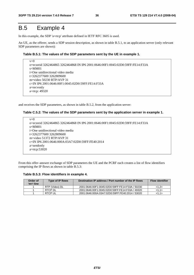
ETSI
ETSI TS 129 214 V7.4.0 (2008-04) 363GPP TS 29.214 version 7.4.0 Release 7
B.5 Example 4 In this example, the SDP 'a=rtcp' attribute defined in IETF RFC 3605 is used.
An UE, as the offerer, sends a SDP session description, as shown in table B.5.1, to an application server (only relevant SDP parameters are shown):
Table B.5.1: The values of the SDP parameters sent by the UE in example 1.
v=0 o=ecsreid 3262464865 3262464868 IN IP6 2001:0646:00F1:0045:02D0:59FF:FE14:F33A s=MM01 i=One unidirectional video media t=3262377600 3262809600 m=video 50230 RTP/AVP 31 c=IN IP6 2001:0646:00F1:0045:02D0:59FF:FE14:F33A a=recvonly a=rtcp: 49320
and receives the SDP parameters, as shown in table B.5.2, from the application server:
Table C.5.2: The values of the SDP parameters sent by the application server in example 1.
v=0 o=ecsreid 3262464865 3262464868 IN IP6 2001:0646:00F1:0045:02D0:59FF:FE14:F33A s=MM01 i=One unidirectional video media t=3262377600 3262809600 m=video 51372 RTP/AVP 31 c=IN IP6 2001:0646:000A:03A7:02D0:59FF:FE40:2014 a=sendonly a=rtcp:53020
From this offer–answer exchange of SDP parameters the UE and the PCRF each creates a list of flow identifiers comprising the IP flows as shown in table B.5.3:
Table B.5.3: Flow identifiers in example 4.
Order of 'm='-line
Type of IP flows Destination IP address / Port number of the IP flows Flow identifier
1 RTP (Video) DL 2001:0646:00F1:0045:02D0:59FF:FE14:F33A / 50230 <1,2> 1 RTCP DL 2001:0646:00F1:0045:02D0:59FF:FE14:F33A / 49320 <1,1> 1 RTCP UL 2001:0646:000A:03A7:02D0:59FF:FE40:2014 / 53020 <1,1>
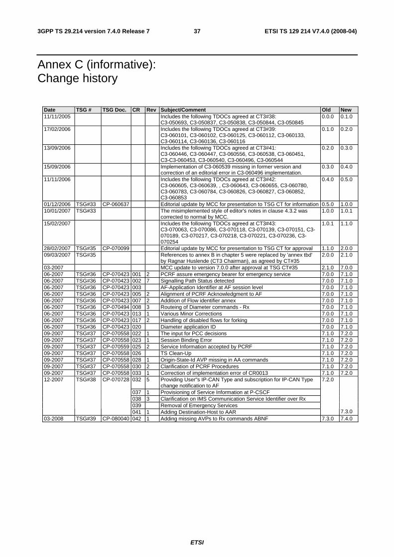
ETSI
ETSI TS 129 214 V7.4.0 (2008-04) 373GPP TS 29.214 version 7.4.0 Release 7
Annex C (informative): Change history
Date TSG # TSG Doc. CR Rev Subject/Comment Old New 11/11/2005 Includes the following TDOCs agreed at CT3#38:
C3-050693, C3-050837, C3-050838, C3-050844, C3-050845 0.0.0 0.1.0
17/02/2006 Includes the following TDOCs agreed at CT3#39: C3-060101, C3-060102, C3-060125, C3-060112, C3-060133, C3-060114, C3-060136, C3-060116
0.1.0 0.2.0
13/09/2006 Includes the following TDOCs agreed at CT3#41: C3-060446, C3-060447, C3-060556, C3-060538, C3-060451, C3-C3-060453, C3-060540, C3-060496, C3-060544
0.2.0 0.3.0
15/09/2006 Implementation of C3-060539 missing in former version and correction of an editorial error in C3-060496 implementation.
0.3.0 0.4.0
11/11/2006 Includes the following TDOCs agreed at CT3#42: C3-060605, C3-060639, , C3-060643, C3-060655, C3-060780, C3-060783, C3-060784, C3-060826, C3-060827, C3-060852, C3-060853
0.4.0 0.5.0
01/12/2006 TSG#33 CP-060637 Editorial update by MCC for presentation to TSG CT for information 0.5.0 1.0.0 10/01/2007 TSG#33 The misimplemented style of editor's notes in clause 4.3.2 was
corrected to normal by MCC. 1.0.0 1.0.1
15/02/2007 Includes the following TDOCs agreed at CT3#43: C3-070063, C3-070086, C3-070118, C3-070139, C3-070151, C3-070189, C3-070217, C3-070218, C3-070221, C3-070236, C3-070254
1.0.1 1.1.0
28/02/2007 TSG#35 CP-070099 Editorial update by MCC for presentation to TSG CT for approval 1.1.0 2.0.0 09/03/2007 TSG#35 References to annex B in chapter 5 were replaced by 'annex tbd'
by Ragnar Huslende (CT3 Chairman), as agreed by CT#35 2.0.0 2.1.0
03-2007 MCC update to version 7.0.0 after approval at TSG CT#35 2.1.0 7.0.0 06-2007 TSG#36 CP-070423 001 2 PCRF assure emergency bearer for emergency service 7.0.0 7.1.0 06-2007 TSG#36 CP-070423 002 7 Signalling Path Status detected 7.0.0 7.1.0 06-2007 TSG#36 CP-070423 003 AF-Application Identifier at AF session level 7.0.0 7.1.0 06-2007 TSG#36 CP-070423 005 2 Alignment of PCRF Acknowledgment to AF 7.0.0 7.1.0 06-2007 TSG#36 CP-070423 007 2 Addition of Flow identifier annex 7.0.0 7.1.0 06-2007 TSG#36 CP-070494 008 3 Routeing of Diameter commands - Rx 7.0.0 7.1.0 06-2007 TSG#36 CP-070423 013 1 Various Minor Corrections 7.0.0 7.1.0 06-2007 TSG#36 CP-070423 017 2 Handling of disabled flows for forking 7.0.0 7.1.0 06-2007 TSG#36 CP-070423 020 Diameter application ID 7.0.0 7.1.0 09-2007 TSG#37 CP-070558 022 1 The input for PCC decisions 7.1.0 7.2.0 09-2007 TSG#37 CP-070558 023 1 Session Binding Error 7.1.0 7.2.0 09-2007 TSG#37 CP-070559 025 2 Service Information accepted by PCRF 7.1.0 7.2.0 09-2007 TSG#37 CP-070558 026 TS Clean-Up 7.1.0 7.2.0 09-2007 TSG#37 CP-070558 028 1 Origin-State-Id AVP missing in AA commands 7.1.0 7.2.0 09-2007 TSG#37 CP-070558 030 2 Clarification of PCRF Procedures 7.1.0 7.2.0 09-2007 TSG#37 CP-070558 033 1 Correction of implementation error of CR0013 7.1.0 7.2.0
032 5 Providing User"s IP-CAN Type and subscription for IP-CAN Type change notification to AF
037 1 Provisioning of Service Information at P-CSCF 038 3 Clarification on IMS Communication Service Identifier over Rx 039 Removal of Emergency Services
12-2007 TSG#38 CP-070728
041 1 Adding Destination-Host to AAR
7.2.0
7.3.0 03-2008 TSG#39 CP-080040 042 1 Adding missing AVPs to Rx commands ABNF 7.3.0 7.4.0

ETSI
ETSI TS 129 214 V7.4.0 (2008-04) 383GPP TS 29.214 version 7.4.0 Release 7
History
Document history
V7.1.0 June 2007 Publication
V7.2.0 October 2007 Publication
V7.3.0 January 2008 Publication
V7.4.0 April 2008 Publication