3l v6 tdi - static.nhtsa.gov · introduction 1 the success story for v6 tdi engines at audi began...
TRANSCRIPT

The Second Generation 3.0L V6 TDI Engine
Self-Study Program 920213
Audi of America, LLC
Service Training
Printed in U.S.A.
Printed 9/2012
Course Number 920213
©2012 Audi of America, LLC
All rights reserved. Information contained in this manual is
based on the latest information available at the time of printing
and is subject to the copyright and other intellectual property
rights of Audi of America, LLC., its affi liated companies and its
licensors. All rights are reserved to make changes at any time
without notice. No part of this document may be reproduced,
stored in a retrieval system, or transmitted in any form or by
any means, electronic, mechanical, photocopying, recording or
otherwise, nor may these materials be modifi ed or reposted to
other sites without the prior expressed written permission of
the publisher.
All requests for permission to copy and redistribute
information should be referred to Audi of America, LLC.
Always check Technical Bulletins and the latest electronic
service repair literature for information that may supersede any
information included in this booklet.
Table of Contents
Introduction . . . . . . . . . . . . . . . . . . . . . . . . . . . . . . . . . . . . . . .1 Technical Features . . . . . . . . . . . . . . . . . . . . . . . . . . . . . . . . . . . . . . . . . . . . . . . . . . . 2
Specifi cations . . . . . . . . . . . . . . . . . . . . . . . . . . . . . . . . . . . . . . . . . . . . . . . . . . . . . . . 4
Engine Design . . . . . . . . . . . . . . . . . . . . . . . . . . . . . . . . . . . . .5 Cylinder Block . . . . . . . . . . . . . . . . . . . . . . . . . . . . . . . . . . . . . . . . . . . . . . . . . . . . . . . 5
Crankshaft Assembly . . . . . . . . . . . . . . . . . . . . . . . . . . . . . . . . . . . . . . . . . . . . . . . . 6
Chain Drive System . . . . . . . . . . . . . . . . . . . . . . . . . . . . . . . . . . . . . . . . . . . . . . . . . . 7
Cylinder Head . . . . . . . . . . . . . . . . . . . . . . . . . . . . . . . . . . . . . . . . . . . . . . . . . . . . . . . 8
Oil Circuit . . . . . . . . . . . . . . . . . . . . . . . . . . . . . . . . . . . . . . . . . .9 Oil Circuit . . . . . . . . . . . . . . . . . . . . . . . . . . . . . . . . . . . . . . . . . . . . . . . . . . . . . . . . . . . 9
Engine Oil Pump with Integral Vacuum Pump . . . . . . . . . . . . . . . . . . . . . . . . . . 10
Engine Oil Cooler with Thermostat Controlled Bypass Port. . . . . . . . . . . . . . 11
Cooling System . . . . . . . . . . . . . . . . . . . . . . . . . . . . . . . . . . .12 Overview . . . . . . . . . . . . . . . . . . . . . . . . . . . . . . . . . . . . . . . . . . . . . . . . . . . . . . . . . . 12
Coolant Circuit and Thermal Management System . . . . . . . . . . . . . . . . . . . . . 13
Cylinder Head Cooling Circuit . . . . . . . . . . . . . . . . . . . . . . . . . . . . . . . . . . . . . . . . 14
Cylinder Block Cooling Circuit . . . . . . . . . . . . . . . . . . . . . . . . . . . . . . . . . . . . . . . . 15
Exhaust Gas Recirculation . . . . . . . . . . . . . . . . . . . . . . . . . .16 Overview . . . . . . . . . . . . . . . . . . . . . . . . . . . . . . . . . . . . . . . . . . . . . . . . . . . . . . . . . . 16
Active EGR Cooler . . . . . . . . . . . . . . . . . . . . . . . . . . . . . . . . . . . . . . . . . . . . . . . . . . 17
Intake Air Ducting . . . . . . . . . . . . . . . . . . . . . . . . . . . . . . . . .18
Turbocharging . . . . . . . . . . . . . . . . . . . . . . . . . . . . . . . . . . . .19 Charge Air Cooling . . . . . . . . . . . . . . . . . . . . . . . . . . . . . . . . . . . . . . . . . . . . . . . . . 20
Common Rail Injection System . . . . . . . . . . . . . . . . . . . . .21 Chain-Driven Injection System . . . . . . . . . . . . . . . . . . . . . . . . . . . . . . . . . . . . . . . 21
Fuel Delivery System . . . . . . . . . . . . . . . . . . . . . . . . . . . . . . . . . . . . . . . . . . . . . . . 22
Engine Management . . . . . . . . . . . . . . . . . . . . . . . . . . . . . . .24 System Overview . . . . . . . . . . . . . . . . . . . . . . . . . . . . . . . . . . . . . . . . . . . . . . . . . . 24
Special Tools and Workshop Equipment . . . . . . . . . . . . .26
Knowledge Assessment . . . . . . . . . . . . . . . . . . . . . . . . . . .29
i

ii
Reference Note
!
The Self-Study Program provides introductory information regarding the design
and function of new models, automotive components, or technologies.
The Self-Study Program is not a Repair Manual!All values given are intended as a guideline only.
For maintenance and repair work, always refer to current technical literature.
Introduction
1
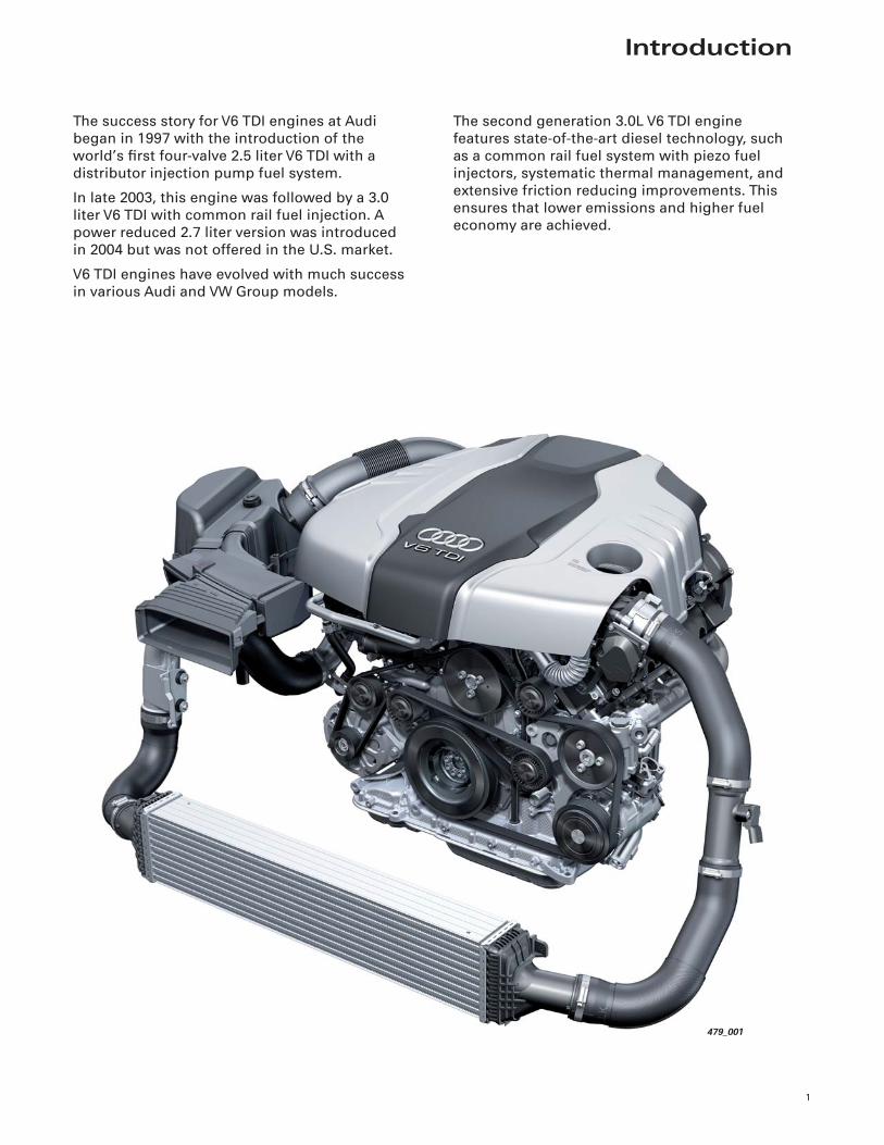
The success story for V6 TDI engines at Audi
began in 1997 with the introduction of the
world’s fi rst four-valve 2.5 liter V6 TDI with a
distributor injection pump fuel system.
In late 2003, this engine was followed by a 3.0
liter V6 TDI with common rail fuel injection. A
power reduced 2.7 liter version was introduced
in 2004 but was not offered in the U.S. market.
V6 TDI engines have evolved with much success
in various Audi and VW Group models.
The second generation 3.0L V6 TDI engine
features state-of-the-art diesel technology, such
as a common rail fuel system with piezo fuel
injectors, systematic thermal management, and
extensive friction reducing improvements. This
ensures that lower emissions and higher fuel
economy are achieved.
479_001
2
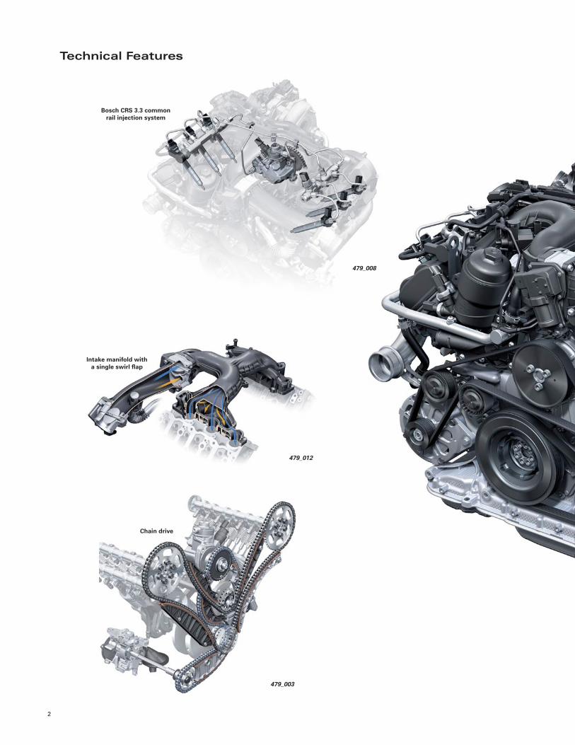
Intake manifold with a single swirl fl ap
479_012
Bosch CRS 3.3 common rail injection system
479_008
Chain drive
479_003
Technical Features
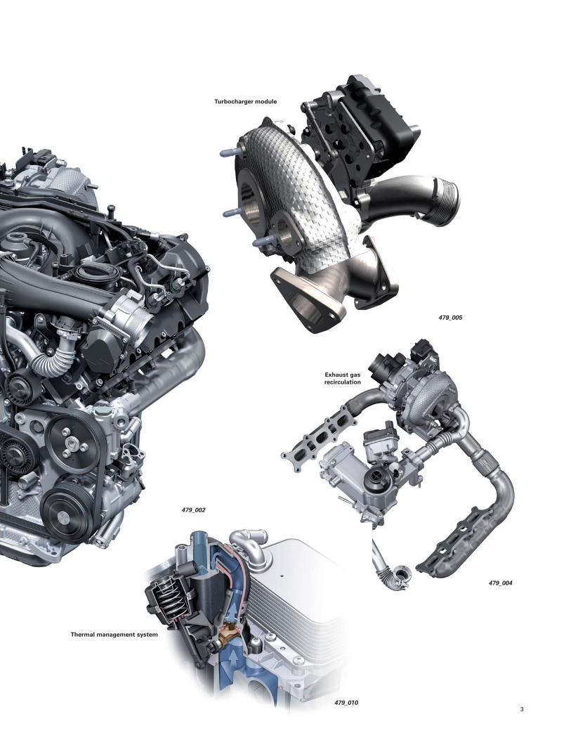
3
479_002
Turbocharger module
479_005
Exhaust gas recirculation
479_010
Thermal management system
479_004
4
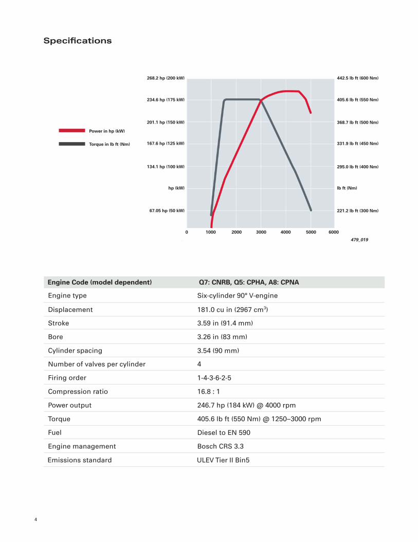
Engine type
Displacement
Stroke
Bore
Cylinder spacing
Number of valves per cylinder
Firing order
Compression ratio
Power output
Six-cylinder 90° V-engine
181.0 cu in (2967 cm3)
3.59 in (91.4 mm)
3.26 in (83 mm)
3.54 (90 mm)
4
1-4-3-6-2-5
16.8 : 1
246.7 hp (184 kW) @ 4000 rpm
Engine Code (model dependent) Q7: CNRB, Q5: CPHA, A8: CPNA
Torque
Fuel
Engine management
405.6 lb ft (550 Nm) @ 1250–3000 rpm
Diesel to EN 590
Bosch CRS 3.3
Power in hp (kW)
Torque in lb ft (Nm)
479_019
234.6 hp (175 kW)
201.1 hp (150 kW)
167.6 hp (125 kW)
134.1 hp (100 kW)
268.2 hp (200 kW)
hp (kW)
0
67.05 hp (50 kW)
405.6 lb ft (550 Nm)
368.7 lb ft (500 Nm)
331.9 lb ft (450 Nm)
295.0 lb ft (400 Nm)
442.5 lb ft (600 Nm)
lb ft (Nm)
221.2 lb ft (300 Nm)
2000 3000 4000 60001000 5000
Specifi cations
Emissions standard ULEV Tier II Bin5
Engine Design
5
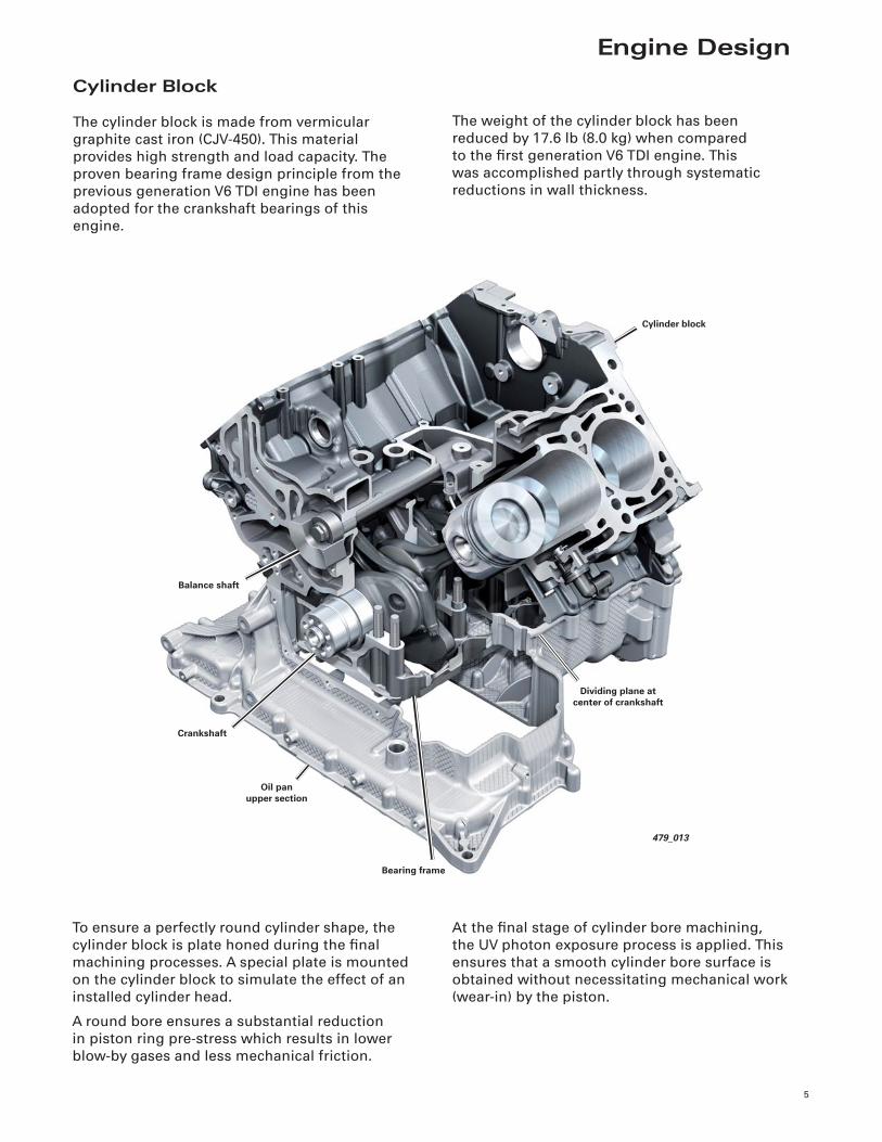
Cylinder Block
The cylinder block is made from vermicular
graphite cast iron (CJV-450). This material
provides high strength and load capacity. The
proven bearing frame design principle from the
previous generation V6 TDI engine has been
adopted for the crankshaft bearings of this
engine.
The weight of the cylinder block has been
reduced by 17.6 lb (8.0 kg) when compared
to the fi rst generation V6 TDI engine. This
was accomplished partly through systematic
reductions in wall thickness.
To ensure a perfectly round cylinder shape, the
cylinder block is plate honed during the fi nal
machining processes. A special plate is mounted
on the cylinder block to simulate the effect of an
installed cylinder head.
A round bore ensures a substantial reduction
in piston ring pre-stress which results in lower
blow-by gases and less mechanical friction.
At the fi nal stage of cylinder bore machining,
the UV photon exposure process is applied. This
ensures that a smooth cylinder bore surface is
obtained without necessitating mechanical work
(wear-in) by the piston.
479_013
Balance shaft
Cylinder block
Oil panupper section
Crankshaft
Dividing plane at center of crankshaft
Bearing frame
6
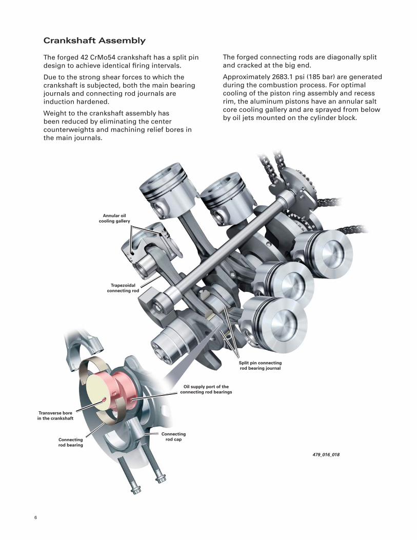
479_016_018
Annular oil cooling gallery
Split pin connecting rod bearing journal
Trapezoidal connecting rod
Connectingrod bearing
Oil supply port of the connecting rod bearings
Transverse bore in the crankshaft
Connecting rod cap
The forged connecting rods are diagonally split
and cracked at the big end.
Approximately 2683.1 psi (185 bar) are generated
during the combustion process. For optimal
cooling of the piston ring assembly and recess
rim, the aluminum pistons have an annular salt
core cooling gallery and are sprayed from below
by oil jets mounted on the cylinder block.
Crankshaft Assembly
The forged 42 CrMo54 crankshaft has a split pin
design to achieve identical fi ring intervals.
Due to the strong shear forces to which the
crankshaft is subjected, both the main bearing
journals and connecting rod journals are
induction hardened.
Weight to the crankshaft assembly has
been reduced by eliminating the center
counterweights and machining relief bores in
the main journals.
7
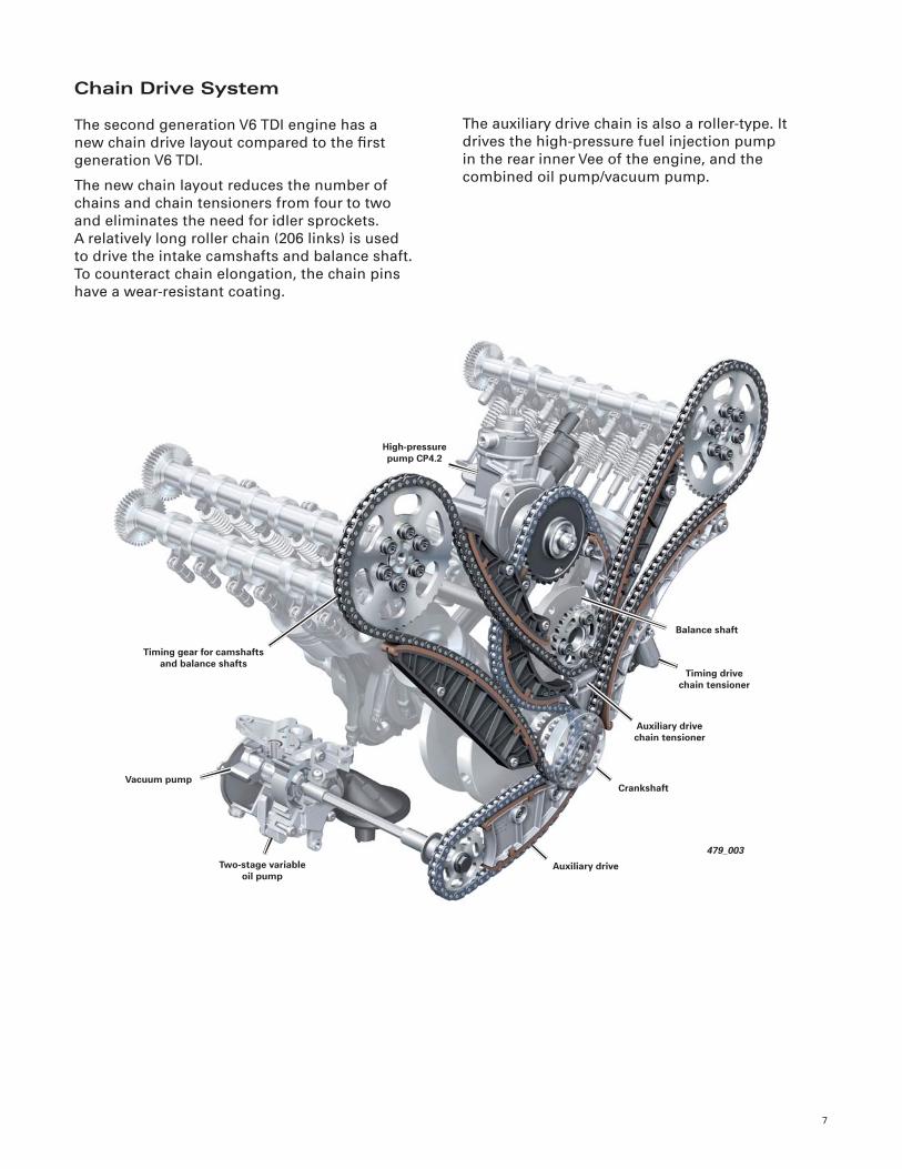
Chain Drive System
The second generation V6 TDI engine has a
new chain drive layout compared to the fi rst
generation V6 TDI.
The new chain layout reduces the number of
chains and chain tensioners from four to two
and eliminates the need for idler sprockets.
A relatively long roller chain (206 links) is used
to drive the intake camshafts and balance shaft.
To counteract chain elongation, the chain pins
have a wear-resistant coating.
The auxiliary drive chain is also a roller-type. It
drives the high-pressure fuel injection pump
in the rear inner Vee of the engine, and the
combined oil pump/vacuum pump.
479_003
Balance shaft
High-pressure pump CP4.2
Crankshaft
Timing drive chain tensioner
Auxiliary drive chain tensioner
Auxiliary driveTwo-stage variable oil pump
Vacuum pump
Timing gear for camshafts and balance shafts
8
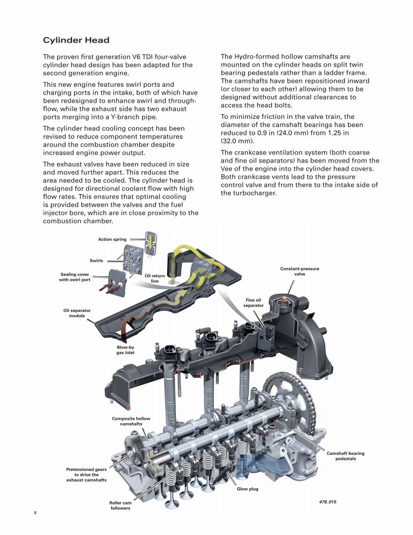
The Hydro-formed hollow camshafts are
mounted on the cylinder heads on split twin
bearing pedestals rather than a ladder frame.
The camshafts have been repositioned inward
(or closer to each other) allowing them to be
designed without additional clearances to
access the head bolts.
To minimize friction in the valve train, the
diameter of the camshaft bearings has been
reduced to 0.9 in (24.0 mm) from 1.25 in
(32.0 mm).
The crankcase ventilation system (both coarse
and fi ne oil separators) has been moved from the
Vee of the engine into the cylinder head covers.
Both crankcase vents lead to the pressure
control valve and from there to the intake side of
the turbocharger.
479_015
Constant-pressure valve
Action spring
Pretensioned gears to drive the
exhaust camshafts
Fine oil separator
Composite hollow camshafts
Swirls
Sealing cover with swirl port
Oil separator module
Oil return line
Blow-by gas inlet
Roller cam followers
Glow plug
Camshaft bearing pedestals
Cylinder Head
The proven fi rst generation V6 TDI four-valve
cylinder head design has been adapted for the
second generation engine.
This new engine features swirl ports and
charging ports in the intake, both of which have
been redesigned to enhance swirl and through-
fl ow, while the exhaust side has two exhaust
ports merging into a Y-branch pipe.
The cylinder head cooling concept has been
revised to reduce component temperatures
around the combustion chamber despite
increased engine power output.
The exhaust valves have been reduced in size
and moved further apart. This reduces the
area needed to be cooled. The cylinder head is
designed for directional coolant fl ow with high
fl ow rates. This ensures that optimal cooling
is provided between the valves and the fuel
injector bore, which are in close proximity to the
combustion chamber.
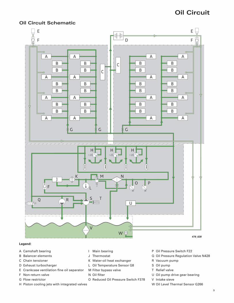
Oil Circuit
9
Oil Circuit Schematic
I Main bearing
J Thermostat
K Water-oil heat exchanger
L Oil Temperature Sensor G8
M Filter bypass valve
N Oil fi lter
O Reduced Oil Pressure Switch F378
A Camshaft bearing
B Balancer elements
C Chain tensioner
D Exhaust turbocharger
E Crankcase ventilation fi ne oil separator
F Non-return valve
G Flow restrictor
H Piston cooling jets with integrated valves
Legend:
P Oil Pressure Switch F22
Q Oil Pressure Regulation Valve N428
R Vacuum pump
S Oil pump
T Relief valve
U Oil pump drive gear bearing
V Intake sieve
W Oil Level Thermal Sensor G266
479_028
10
ReferenceFor more detailed information about the fl ow rate controlled oil pump, refer to Self-Study Program 941803,
Audi 3.0-liter V6 TDI With Clean Diesel System.
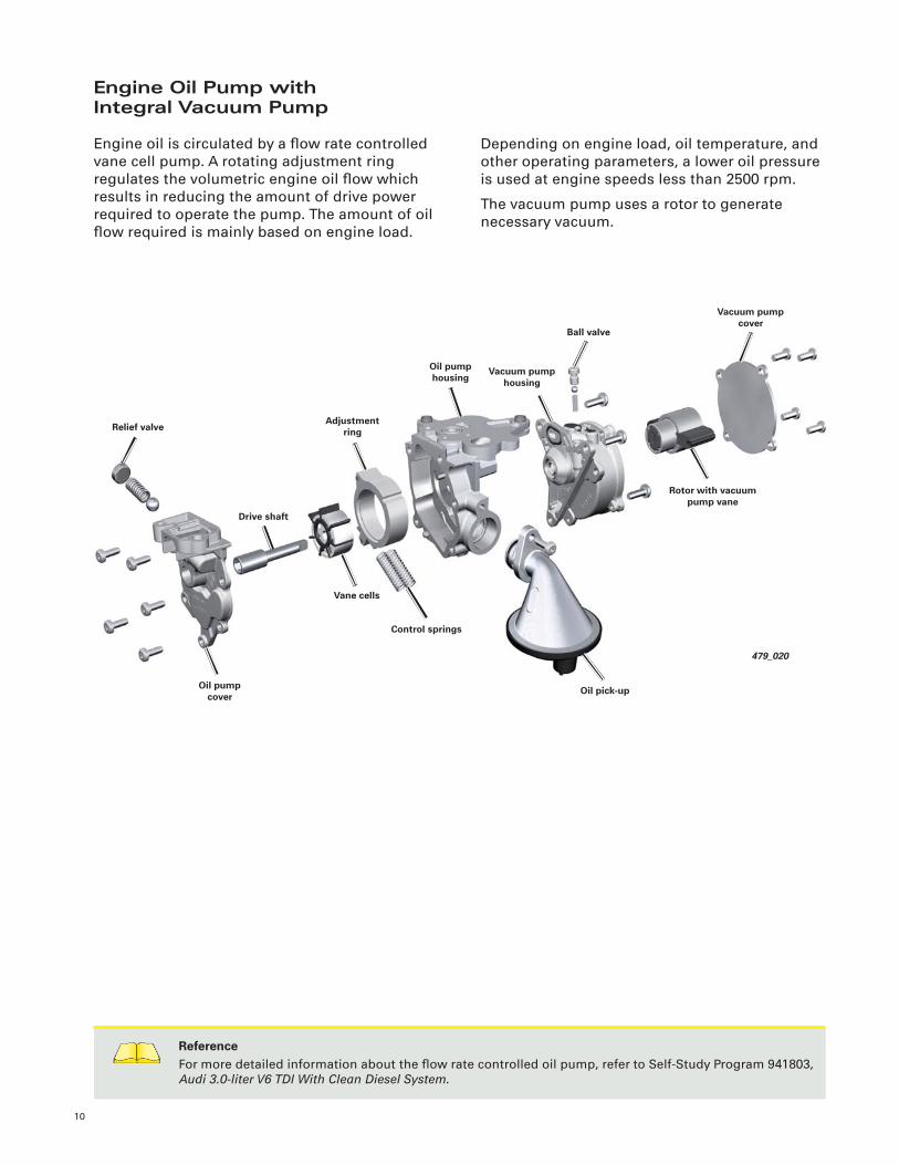
Engine Oil Pump withIntegral Vacuum Pump
Engine oil is circulated by a fl ow rate controlled
vane cell pump. A rotating adjustment ring
regulates the volumetric engine oil fl ow which
results in reducing the amount of drive power
required to operate the pump. The amount of oil
fl ow required is mainly based on engine load.
Depending on engine load, oil temperature, and
other operating parameters, a lower oil pressure
is used at engine speeds less than 2500 rpm.
The vacuum pump uses a rotor to generate
necessary vacuum.
479_020
Vacuum pump cover
Oil pump housing
Vane cells
Ball valve
Control springs
Adjustment ring
Oil pump cover
Relief valve
Vacuum pump housing
Drive shaft
Rotor with vacuum pump vane
Oil pick-up
11
479_030
Coolant pump drive gear mounting
Thermostat
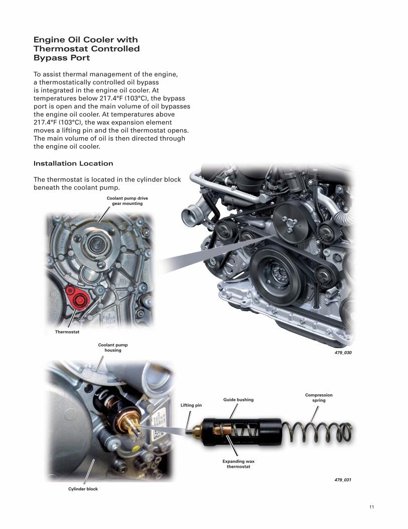
Engine Oil Cooler with Thermostat ControlledBypass Port
To assist thermal management of the engine,
a thermostatically controlled oil bypass
is integrated in the engine oil cooler. At
temperatures below 217.4°F (103°C), the bypass
port is open and the main volume of oil bypasses
the engine oil cooler. At temperatures above
217.4°F (103°C), the wax expansion element
moves a lifting pin and the oil thermostat opens.
The main volume of oil is then directed through
the engine oil cooler.
Installation Location
The thermostat is located in the cylinder block
beneath the coolant pump.
Lifting pin
Coolant pump housing
Cylinder block
Expanding wax thermostat
Compression spring
479_031
Guide bushing
Cooling System
12
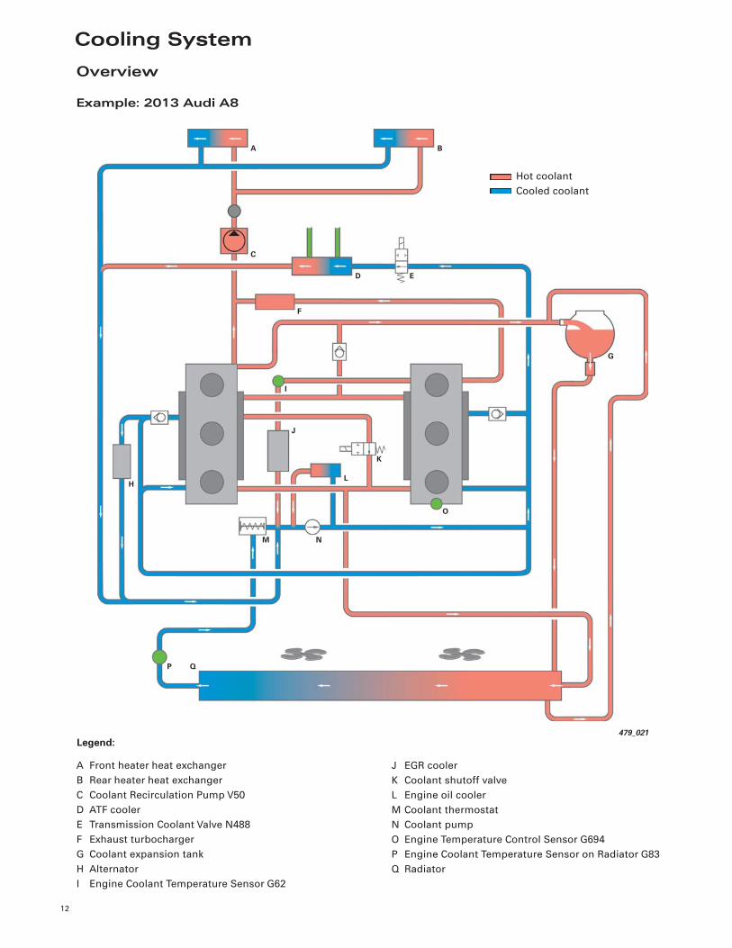
Overview
Example: 2013 Audi A8
479_021
BA
H
G
J
C
E
F
D
I
L
K
O
M N
P Q
J EGR cooler
K Coolant shutoff valve
L Engine oil cooler
M Coolant thermostat
N Coolant pump
O Engine Temperature Control Sensor G694
P Engine Coolant Temperature Sensor on Radiator G83
Q Radiator
A Front heater heat exchanger
B Rear heater heat exchanger
C Coolant Recirculation Pump V50
D ATF cooler
E Transmission Coolant Valve N488
F Exhaust turbocharger
G Coolant expansion tank
H Alternator
I Engine Coolant Temperature Sensor G62
Legend:
Hot coolant
Cooled coolant
13
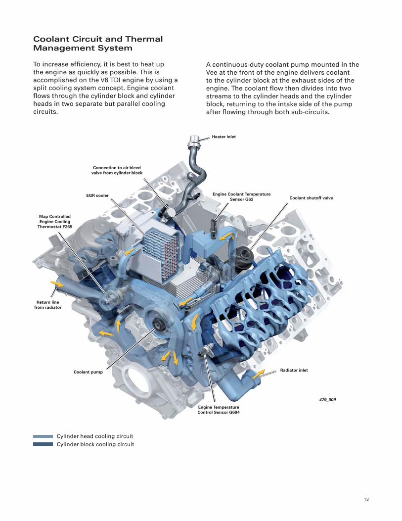
Coolant Circuit and Thermal Management System
To increase effi ciency, it is best to heat up
the engine as quickly as possible. This is
accomplished on the V6 TDI engine by using a
split cooling system concept. Engine coolant
fl ows through the cylinder block and cylinder
heads in two separate but parallel cooling
circuits.
A continuous-duty coolant pump mounted in the
Vee at the front of the engine delivers coolant
to the cylinder block at the exhaust sides of the
engine. The coolant fl ow then divides into two
streams to the cylinder heads and the cylinder
block, returning to the intake side of the pump
after fl owing through both sub-circuits.
Cylinder head cooling circuit
Cylinder block cooling circuit
479_009
Engine Coolant Temperature Sensor G62
Heater inlet
Radiator inlet
Coolant shutoff valve
Connection to air bleed valve from cylinder block
EGR cooler
Map Controlled Engine Cooling
Thermostat F265
Return line from radiator
Coolant pump
Engine Temperature Control Sensor G694
14
NoteThe cooling system is equipped with a control valve and can only be fi lled using VAS 6096 (vacuum fi lling).
Follow all instructions outlined in current technical literature.!
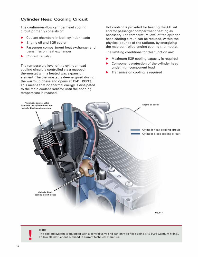
Cylinder Head Cooling Circuit
The continuous-fl ow cylinder head cooling
circuit primarily consists of:
• Coolant chambers in both cylinder heads
• Engine oil and EGR cooler
• Passenger compartment heat exchanger and
transmission heat exchanger
• Coolant radiator
The temperature level of the cylinder head
cooling circuit is controlled via a mapped
thermostat with a heated wax expansion
element. The thermostat is de-energized during
the warm-up phase and opens at 194°F (90°C).
This means that no thermal energy is dissipated
to the main coolant radiator until the opening
temperature is reached.
Hot coolant is provided for heating the ATF oil
and for passenger compartment heating as
necessary. The temperature level of the cylinder
head cooling circuit can be reduced, within the
physical bounds of the radiator, by energizing
the map-controlled engine cooling thermostat.
The limiting conditions for this function are:
• Maximum EGR cooling capacity is required
• Component protection of the cylinder head
under high component load
• Transmission cooling is required
479_011
Pneumatic control valve(controls the cylinder head and cylinder block cooling system)
Engine oil cooler
Cylinder block cooling circuit closed
Cylinder head cooling circuit
Cylinder block cooling circuit
15
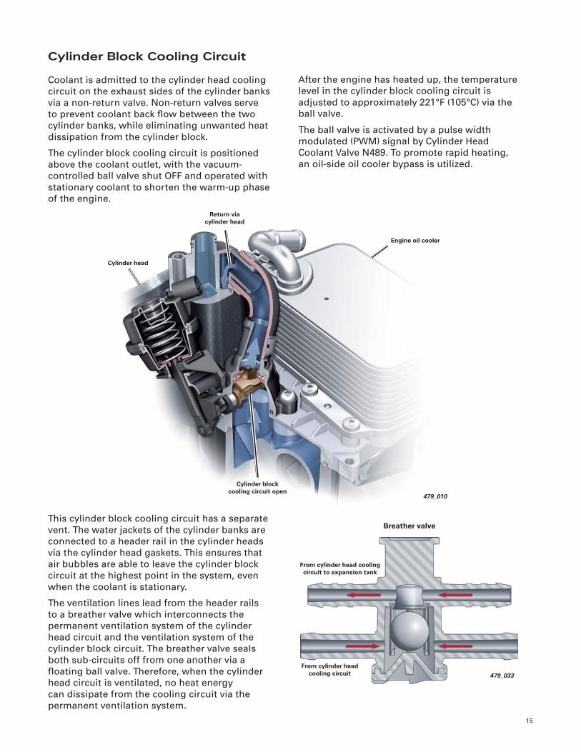
479_010
Engine oil cooler
Cylinder head
Cylinder block cooling circuit open
Return via cylinder head
Cylinder Block Cooling Circuit
Coolant is admitted to the cylinder head cooling
circuit on the exhaust sides of the cylinder banks
via a non-return valve. Non-return valves serve
to prevent coolant back fl ow between the two
cylinder banks, while eliminating unwanted heat
dissipation from the cylinder block.
The cylinder block cooling circuit is positioned
above the coolant outlet, with the vacuum-
controlled ball valve shut OFF and operated with
stationary coolant to shorten the warm-up phase
of the engine.
After the engine has heated up, the temperature
level in the cylinder block cooling circuit is
adjusted to approximately 221°F (105°C) via the
ball valve.
The ball valve is activated by a pulse width
modulated (PWM) signal by Cylinder Head
Coolant Valve N489. To promote rapid heating,
an oil-side oil cooler bypass is utilized.
This cylinder block cooling circuit has a separate
vent. The water jackets of the cylinder banks are
connected to a header rail in the cylinder heads
via the cylinder head gaskets. This ensures that
air bubbles are able to leave the cylinder block
circuit at the highest point in the system, even
when the coolant is stationary.
The ventilation lines lead from the header rails
to a breather valve which interconnects the
permanent ventilation system of the cylinder
head circuit and the ventilation system of the
cylinder block circuit. The breather valve seals
both sub-circuits off from one another via a
fl oating ball valve. Therefore, when the cylinder
head circuit is ventilated, no heat energy
can dissipate from the cooling circuit via the
permanent ventilation system.
479_033
From cylinder head cooling circuit to expansion tank
Breather valve
From cylinder head cooling circuit
Exhaust Gas Recirculation
16
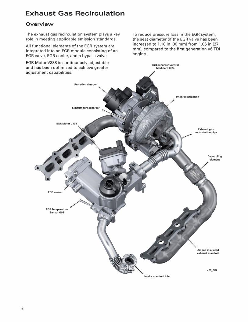
479_004
Integral insulation
Turbocharger Control Module 1 J724
Air gap insulated exhaust manifold
Exhaust gas recirculation pipe
Decoupling element
Intake manifold inlet
EGR Temperature Sensor G98
EGR cooler
EGR Motor V338
Exhaust turbocharger
Pulsation damper
Overview
The exhaust gas recirculation system plays a key
role in meeting applicable emission standards.
All functional elements of the EGR system are
integrated into an EGR module consisting of an
EGR valve, EGR cooler, and a bypass valve.
EGR Motor V338 is continuously adjustable
and has been optimized to achieve greater
adjustment capabilities.
To reduce pressure loss in the EGR system,
the seat diameter of the EGR valve has been
increased to 1.18 in (30 mm) from 1.06 in (27
mm), compared to the fi rst generation V6 TDI
engine.
17
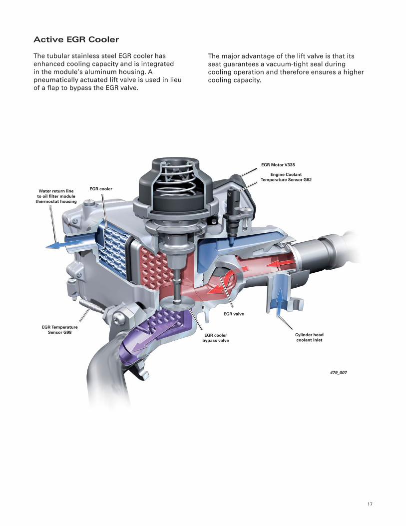
Active EGR Cooler
The tubular stainless steel EGR cooler has
enhanced cooling capacity and is integrated
in the module’s aluminum housing. A
pneumatically actuated lift valve is used in lieu
of a fl ap to bypass the EGR valve.
The major advantage of the lift valve is that its
seat guarantees a vacuum-tight seal during
cooling operation and therefore ensures a higher
cooling capacity.
479_007
Engine Coolant Temperature Sensor G62
EGR Motor V338
EGR Temperature Sensor G98
EGR coolerWater return line to oil fi lter module
thermostat housing
Cylinder head coolant inlet
EGR cooler bypass valve
EGR valve
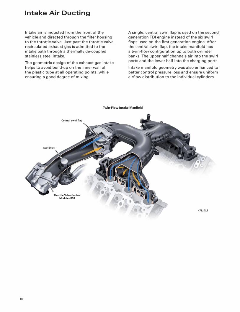
Intake Air Ducting
18
Intake air is inducted from the front of the
vehicle and directed through the fi lter housing
to the throttle valve. Just past the throttle valve,
recirculated exhaust gas is admitted to the
intake path through a thermally de-coupled
stainless steel intake.
The geometric design of the exhaust gas intake
helps to avoid build-up on the inner wall of
the plastic tube at all operating points, while
ensuring a good degree of mixing.
A single, central swirl fl ap is used on the second
generation TDI engine instead of the six swirl
fl aps used on the fi rst generation engine. After
the central swirl fl ap, the intake manifold has
a twin-fl ow confi guration up to both cylinder
banks. The upper half channels air into the swirl
ports and the lower half into the charging ports.
Intake manifold geometry was also enhanced to
better control pressure loss and ensure uniform
airfl ow distribution to the individual cylinders.
479_012
EGR inlet
Central swirl fl ap
Throttle Valve Control Module J338
Twin-Flow Intake Manifold
Turbocharging
19
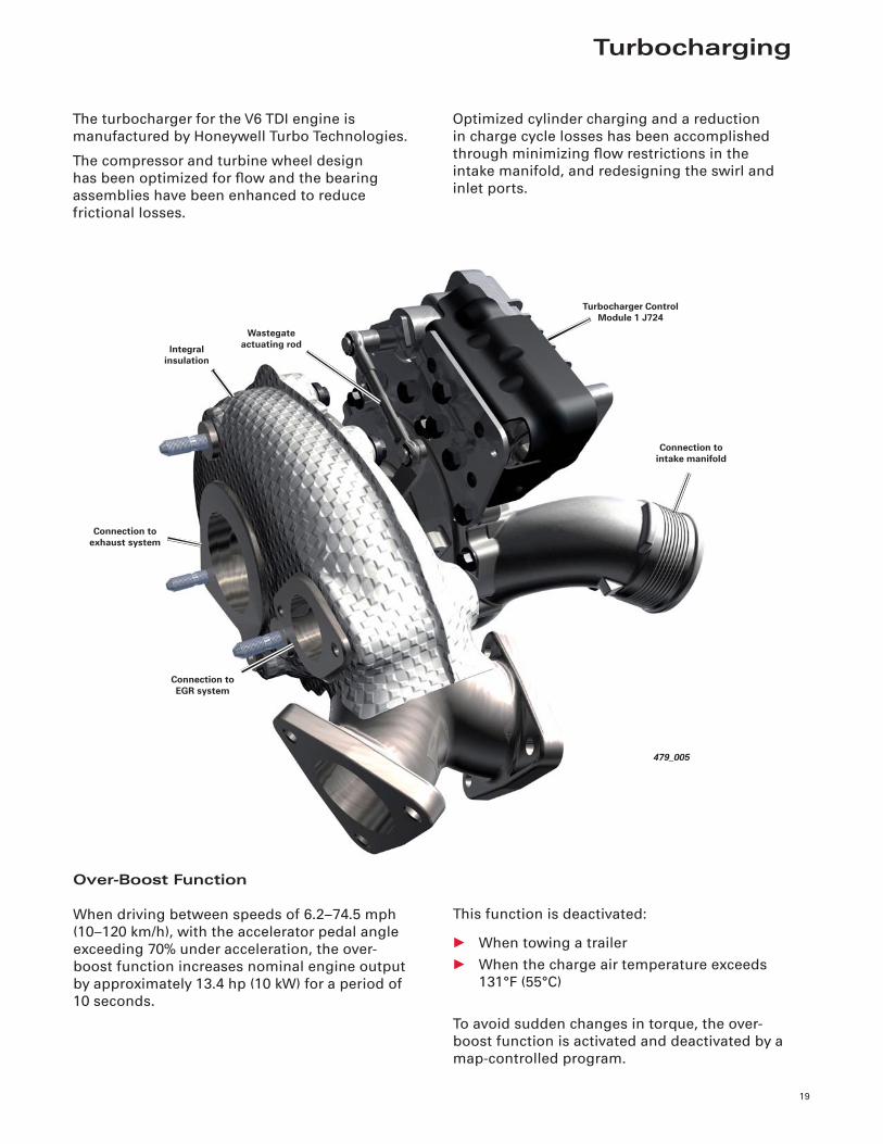
479_005
Turbocharger Control Module 1 J724
Wastegate actuating rod
Connection to EGR system
Integral insulation
Connection to exhaust system
Connection to intake manifold
The turbocharger for the V6 TDI engine is
manufactured by Honeywell Turbo Technologies.
The compressor and turbine wheel design
has been optimized for fl ow and the bearing
assemblies have been enhanced to reduce
frictional losses.
Optimized cylinder charging and a reduction
in charge cycle losses has been accomplished
through minimizing fl ow restrictions in the
intake manifold, and redesigning the swirl and
inlet ports.
Over-Boost Function
When driving between speeds of 6.2–74.5 mph
(10–120 km/h), with the accelerator pedal angle
exceeding 70% under acceleration, the over-
boost function increases nominal engine output
by approximately 13.4 hp (10 kW) for a period of
10 seconds.
This function is deactivated:
• When towing a trailer
• When the charge air temperature exceeds
131°F (55°C)
To avoid sudden changes in torque, the over-
boost function is activated and deactivated by a
map-controlled program.
20
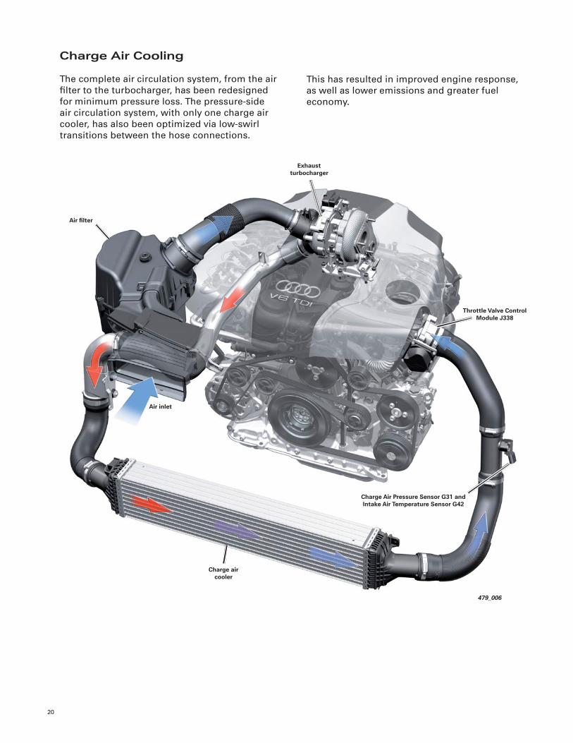
Charge Air Cooling
The complete air circulation system, from the air
fi lter to the turbocharger, has been redesigned
for minimum pressure loss. The pressure-side
air circulation system, with only one charge air
cooler, has also been optimized via low-swirl
transitions between the hose connections.
This has resulted in improved engine response,
as well as lower emissions and greater fuel
economy.
479_006
Throttle Valve Control Module J338
Air fi lter
Exhaust turbocharger
Air inlet
Charge air cooler
Charge Air Pressure Sensor G31 and Intake Air Temperature Sensor G42
Common Rail Injection System
21
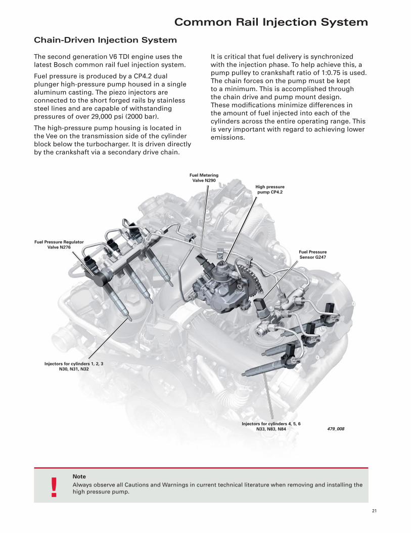
Chain-Driven Injection System
The second generation V6 TDI engine uses the
latest Bosch common rail fuel injection system.
Fuel pressure is produced by a CP4.2 dual
plunger high-pressure pump housed in a single
aluminum casting. The piezo injectors are
connected to the short forged rails by stainless
steel lines and are capable of withstanding
pressures of over 29,000 psi (2000 bar).
The high-pressure pump housing is located in
the Vee on the transmission side of the cylinder
block below the turbocharger. It is driven directly
by the crankshaft via a secondary drive chain.
It is critical that fuel delivery is synchronized
with the injection phase. To help achieve this, a
pump pulley to crankshaft ratio of 1:0.75 is used.
The chain forces on the pump must be kept
to a minimum. This is accomplished through
the chain drive and pump mount design.
These modifi cations minimize differences in
the amount of fuel injected into each of the
cylinders across the entire operating range. This
is very important with regard to achieving lower
emissions.
479_008
Fuel Metering Valve N290
Fuel Pressure Regulator Valve N276
Injectors for cylinders 1, 2, 3N30, N31, N32
High pressure pump CP4.2
Fuel Pressure Sensor G247
Injectors for cylinders 4, 5, 6N33, N83, N84
NoteAlways observe all Cautions and Warnings in current technical literature when removing and installing the
high pressure pump. !
22
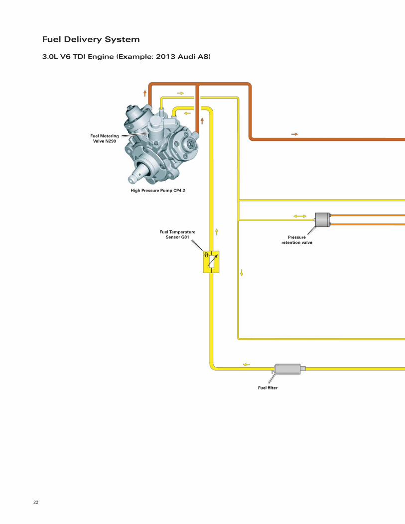
Fuel Delivery System
3.0L V6 TDI Engine (Example: 2013 Audi A8)
Fuel Metering Valve N290
High Pressure Pump CP4.2
Fuel Temperature Sensor G81 Pressure
retention valve
Fuel fi lter
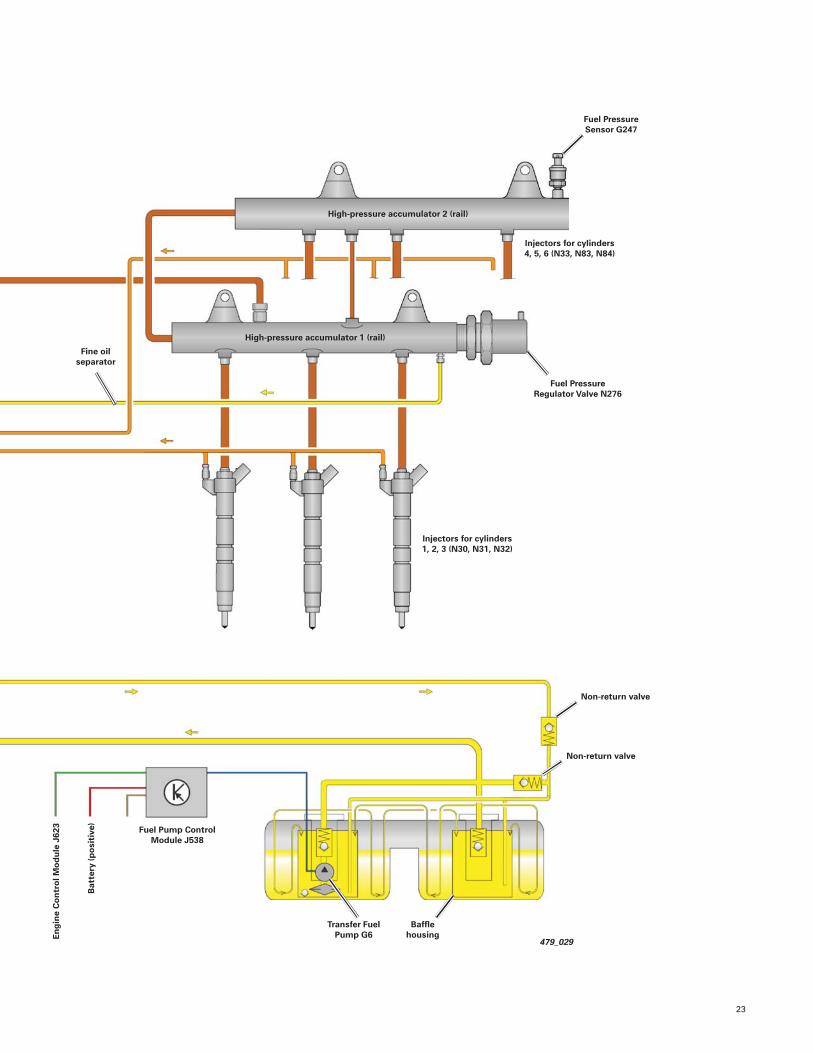
23
479_029
Fuel Pressure Regulator Valve N276
Injectors for cylinders 4, 5, 6 (N33, N83, N84)
Fine oil separator
Transfer Fuel Pump G6
Fuel Pressure Sensor G247
Bat
tery
(pos
itiv
e)
Eng
ine
Con
trol
Mod
ule
J62
3
Non-return valve
High-pressure accumulator 2 (rail)
High-pressure accumulator 1 (rail)
Injectors for cylinders 1, 2, 3 (N30, N31, N32)
Fuel Pump Control Module J538
Baffl e housing
Non-return valve
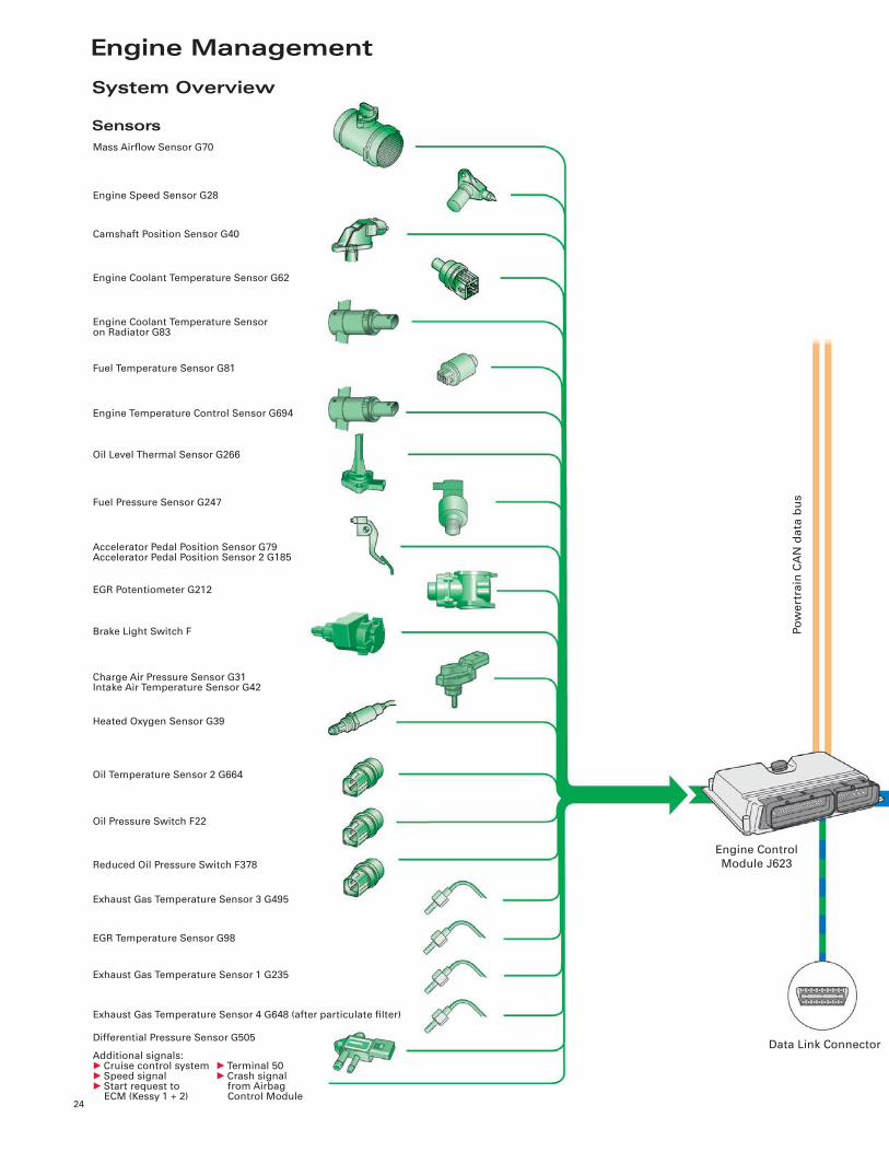
Engine Management
24
System Overview
Sensors
Engine Speed Sensor G28
Data Link Connector
Engine Control
Module J623
Po
we
rtra
in C
AN
da
ta b
us
Mass Airfl ow Sensor G70
Camshaft Position Sensor G40
Engine Coolant Temperature Sensor G62
Engine Coolant Temperature Sensoron Radiator G83
Fuel Temperature Sensor G81
Engine Temperature Control Sensor G694
Oil Level Thermal Sensor G266
Fuel Pressure Sensor G247
Accelerator Pedal Position Sensor G79Accelerator Pedal Position Sensor 2 G185
EGR Potentiometer G212
Brake Light Switch F
Charge Air Pressure Sensor G31Intake Air Temperature Sensor G42
Heated Oxygen Sensor G39
Oil Temperature Sensor 2 G664
Oil Pressure Switch F22
Reduced Oil Pressure Switch F378
Exhaust Gas Temperature Sensor 3 G495
EGR Temperature Sensor G98
Exhaust Gas Temperature Sensor 1 G235
Exhaust Gas Temperature Sensor 4 G648 (after particulate fi lter)
Differential Pressure Sensor G505
Additional signals:• Cruise control system• Speed signal• Start request to ECM (Kessy 1 + 2)
• Terminal 50• Crash signal from Airbag Control Module
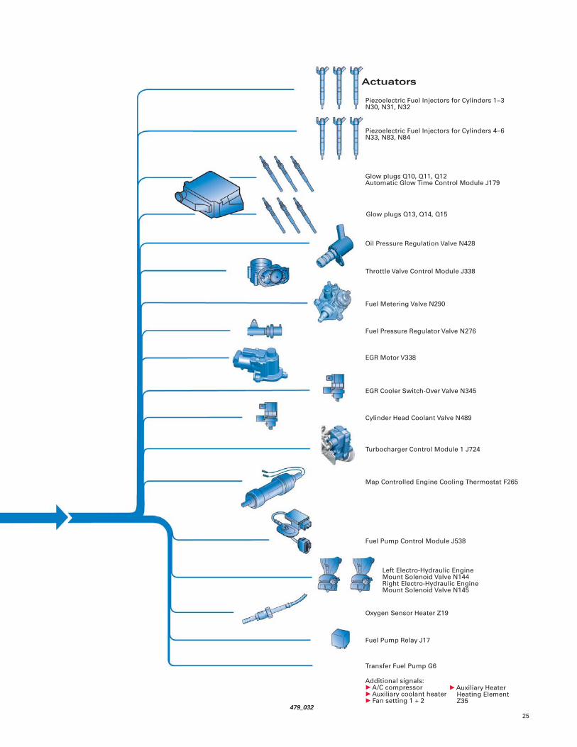
25
Actuators
Piezoelectric Fuel Injectors for Cylinders 1–3 N30, N31, N32
479_032
Piezoelectric Fuel Injectors for Cylinders 4–6 N33, N83, N84
Glow plugs Q10, Q11, Q12Automatic Glow Time Control Module J179
Glow plugs Q13, Q14, Q15
Oil Pressure Regulation Valve N428
Throttle Valve Control Module J338
Fuel Metering Valve N290
Fuel Pressure Regulator Valve N276
EGR Motor V338
EGR Cooler Switch-Over Valve N345
Cylinder Head Coolant Valve N489
Turbocharger Control Module 1 J724
Map Controlled Engine Cooling Thermostat F265
Fuel Pump Control Module J538
Left Electro-Hydraulic EngineMount Solenoid Valve N144Right Electro-Hydraulic EngineMount Solenoid Valve N145
Oxygen Sensor Heater Z19
Fuel Pump Relay J17
Transfer Fuel Pump G6
Additional signals:• A/C compressor• Auxiliary coolant heater• Fan setting 1 + 2
• Auxiliary Heater Heating Element Z35
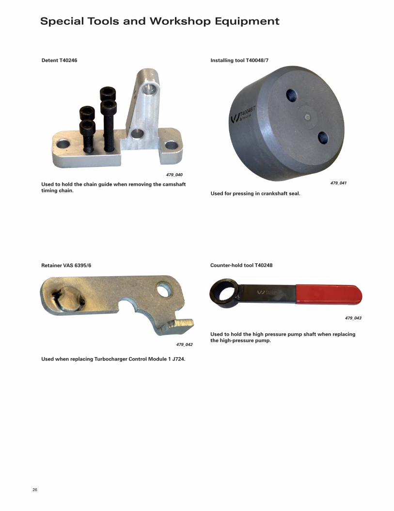
Special Tools and Workshop Equipment
26
Detent T40246
479_040
Used to hold the chain guide when removing the camshaft timing chain.
Retainer VAS 6395/6
479_042
Used when replacing Turbocharger Control Module 1 J724.
479_041
Installing tool T40048/7
Used for pressing in crankshaft seal.
Counter-hold tool T40248
479_043
Used to hold the high pressure pump shaft when replacing the high-pressure pump.
27
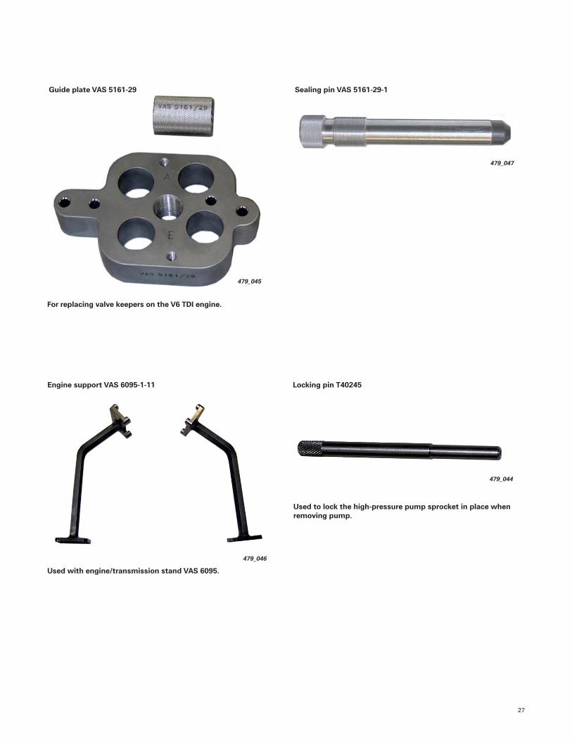
Guide plate VAS 5161-29
479_045
For replacing valve keepers on the V6 TDI engine.
Sealing pin VAS 5161-29-1
479_047
Engine support VAS 6095-1-11
479_046
Used with engine/transmission stand VAS 6095.
479_044
Locking pin T40245
Used to lock the high-pressure pump sprocket in place when removing pump.

Notes
28
Knowledge Assessment
29
An on-line Knowledge Assessment (exam) is available for this Self-Study Program.
The Knowledge Assessment is required for Certifi cation.
You can fi nd this Knowledge Assessment at:
www.accessaudi.com
From the accessaudi.com Homepage:
• Click on the “ACADEMY” tab
• Click on the “Academy Site” link
• Click on Course Catalog Search and select “920213B — The Audi 3.0L V6 TDI Engine
(second generation)”
Please submit any questions or inquiries via the Academy CRC Online Support Form
which is located under the “Support” tab or the “Contact Us” tab of the Academy CRC.
Thank you for reading this Self-Study Program and taking the assessment.

920213
All rights reserved.Technical specifi cations subject to change without notice.
Audi of America, LLC2200 Ferdinand Porsche DriveHerndon, VA 20171