3rd intermediate progress report - cordis · 4 executive summary this deliverable d800.5 3rd...
TRANSCRIPT

3RD INTERMEDIATE PROGRESS REPORT
Deliverable D800.5
Circulation: PU: Public Lead partner: SINTEF Contributing partners: All Authors: Daniel Weber Quality Controllers: Georg Muntingh, Daniel Weber Version: 1.0 Date: 22.03.2016

CloudFlow (FP7-2013-NMP-ICT-FoF- 609100) D800.5
©Copyright 2016: The CloudFlow Consortium
Consisting of
Fraunhofer Fraunhofer Gesellschaft zur Förderung der angewandten Forschung e.V.
SINTEF Stiftelsen SINTEF JOTNE Jotne EPM Technology AS DFKI Deutsches Forschungszentrum für Kuenstliche Intelligenz GmbH
UNott The University of Nottingham CARSA Consultores de Automatizacion y Robotica S.A. NUMECA Numerical Mechanics Applications International SA ITI ITI Gesellschaft für Ingenieurtechnische Informationsverarbeitung MBH
Missler Missler Software ARCTUR Arctur Racunalniski Inzeniring Doo Stellba Stellba Hydro GmbH & Co KG ESS European Sensor Systems SA
Helic HELIC ELLINIKA OLOKLIROMENA KYKLOMATA A.E.
ATHENA ATHENA Research and Innovation Center in Information Communication and
Knowledge Technologies
Introsys Introsys - Integration for Robotic Systems-Integração de Sistemas Roboticos SA
Simplan SimPlan AG
Uni Kassel Universität Kassel
BOGE BOGE KOMPRESSOREN Otto Boge GmbH & Co. KG
CapVidia CapVidia NV
SES-Tec SES-Tec OG
AVL AVL List GmbH
nablaDOT nablaDot SL
BioCurve BioCurve
UNIZAR Universidad de Zaragoza
BTECH Barcelona Technical Center SL
CSUC Consorci de Serveis Universitaris de Catalunya
TTS Technology Transfer System s.r.l.
FICEP FICEP S.p.a.
SUPSI Scuola universitaria professionale della Svizzera italiana
This document may not be copied, reproduced, or modified in whole or in part for any purpose
without written permission from the CloudFlow Consortium. In addition to such written permission
to copy, reproduce, or modify this document in whole or part, an acknowledgement of the authors of
the document and all applicable portions of the copyright notice must be clearly referenced.
All rights reserved.
This document may change without notice.

D800.5 CloudFlow (FP7-2013-NMP-ICT-FoF- 609100)
3
Document History
Version1 Issue Date Stage Content and Changes
1.0 22.03.2016 100% Version to be submitted to the Project Officer
1 Integers correspond to submitted versions

4
EXECUTIVE SUMMARY
This deliverable D800.5 3rd Intermediate Progress Report is the fifth progress report of the CloudFlow
consortium and project. It has been agreed during the negotiation period that there will be eight
progress reports within CloudFlow: four intermediate progress reports (after M7, M19, M31 and
M37), three periodic progress reports (M13, M25 and M42), and a final report due in M42. The
project management is responsible for generating the intermediate and periodic progress reports,
which will be used for internal progress checking and will be made available to the Project Officer. An
intermediate report is an informal progress report, while each periodic progress report will follow
the suggested format and EC guidelines.
This report consequently covers the project's activities from Month 25 to Month 30 (July to
December 2015).
The following deliverables are due in the six-month period (M25–M30) and are covered by this
intermediate progress report:
Deliverable number Deliverable name Due date Delivery date
D100.2 1st wave experiment results M25 May, 2015 (M23) D800.4 2nd period progress report M25 February, 2016 (M32)
A draft of the 2nd periodic progress report D800.4 with financial figures was submitted on time, two
weeks before the first project review in M27. However, the second and final version of the periodic
progress report D800.4 was submitted only in M32, due to several complications concerning the
reporting in NEF, especially for the partners that are new to EC projects.
Apart from the reports on the intermediate results of the wave 1 and 2 experiments listed later on in
this document, an overview of the status of these experiments was also given at the 2nd Project
Review in London.
There has been extensive activity in meetings (both teleconferences and in-person meetings) to
address administrative and technical aspects of CloudFlow in the project period M25–M30, including:
Internal experiment reviews (M26–M27) for all experiments in wave 1 and wave 2.
Review meeting (M27)
The review was held during September 24–25 as part of a multi-project review and
collaboration event organized by the CloudSME project at Brunel University, London, during
September 21–25. All CloudFlow partners prepared presentations and demonstrations
regarding the experiments, the CloudFlow infrastructure and the business aspects to show
the progress and the state of the project.
Monthly Project Board meetings.
Monthly administrative meetings for wave 2 experiments.
Bi-weekly teleconferences in the System Design Group.
Technical teleconferences, a total of 10, for wave 2 experiments.
Internal evaluation (M29–M30) for all experiments in wave 2.
Consensus meetings (M29) for the 22 submitted proposals for wave 3.
Preparation of instructions (M30) for Grant Agreement amendment of the selected wave 3
experiments.

D800.5 CloudFlow (FP7-2013-NMP-ICT-FoF- 609100)
5
Beside these major events, many interactions have happened on the level of the sub-groups of the
consortium, as well as many informal teleconferences in the Core Management. In addition,
teleconferences were held with participation from all partners to report progress to the CloudFlow
management on a monthly basis. A comprehensive list of all meetings that took place in the project
period M25–M30 is provided in Section 4.

CloudFlow (FP7-2013-NMP-ICT-FoF- 609100) D800.5
6
TABLE OF CONTENTS
Executive summary ................................................................................................................................. 4
Table of contents ..................................................................................................................................... 6
1 Project objectives for the period ..................................................................................................... 7
2 Experiment work packages ............................................................................................................. 7
2.1 WP100 — Competence Centre ............................................................................................... 8
2.2 WP110 — 1st wave of experiments ....................................................................................... 11
2.3 WP111 — CAD on the Cloud ................................................................................................. 13
2.4 WP112 — CAM on the Cloud ................................................................................................ 16
2.5 WP113 — CFD on the Cloud .................................................................................................. 19
2.6 WP114 — PLM on the Cloud ................................................................................................. 22
2.7 WP115 — Systems Simulation on the Cloud ......................................................................... 26
2.8 WP116 — Point cloud vs CAD Comparison on the Cloud...................................................... 30
2.9 WP120 — 2nd wave of experiments ...................................................................................... 34
2.10 WP121 — Electronics Design Automation (EDA) — Modelling of MEMS Sensors ............... 40
2.11 WP122 — Plant Simulation and Optimization in the CLOUD ................................................ 53
2.12 WP123 — SIMCASE ............................................................................................................... 60
2.13 WP124 — Cloud-Based HPC Supported Cooling Air-Flow Optimization for industrial
machines shown exemplary for compressors ................................................................................... 66
2.14 WP125 — Cloud-Based Multiphase Flow Simulation of a Bioreactor ................................... 79
2.15 WP126 — CFD Design of Biomass Boilers in the Cloud ......................................................... 86
2.16 WP127 — Automobile Light Design: Thermal Simulation of Lighting Systems ..................... 93
2.17 WP130 — 3rd wave of experiments ..................................................................................... 102
3 Infrastructure work packages ...................................................................................................... 105
3.1 WP200 – Data ...................................................................................................................... 106
3.2 WP300 — Services ............................................................................................................... 112
3.3 WP400 — Workflows .......................................................................................................... 120
3.4 WP500 — Users ................................................................................................................... 127
3.5 WP600 — Business Models ................................................................................................. 134
3.6 WP700 — Outreach ............................................................................................................. 141
4 WP800 — Management .............................................................................................................. 148
5 Deliverables and milestones tables ............................................................................................. 159
5.1 Deliverables ......................................................................................................................... 159
5.2 Milestones ........................................................................................................................... 159
6 Annex: Report on 2nd Open Call for Application Experiments .................................................... 160
D800.5 CloudFlow (FP7-2013-NMP-ICT-FoF- 609100)
7
1 PROJECT OBJECTIVES FOR THE PERIOD
The objectives of CloudFlow in the period M25–M30 are reflected in the 2nd Project Review. There
are no milestones in this period.
2nd Project Review (Month 27)
Presentations and demonstrations regarding the experiments, the CloudFlow infrastructure
and the business aspects to show the progress and the state of the project.
2 EXPERIMENT WORK PACKAGES
There is a hierarchy of work packages related to the 1st wave of experiments in CloudFlow, and to
avoid too much duplication of information in the reporting of the separate work packages, the
experiment reporting follows this hierarchy. For each 1st wave experiment there is a dedicated work
package that contains the experiment execution and assessment and validation tasks. The activities
on assessment and validation have been finalized in this period. Work is ongoing related to the first
wave of experiments in WP110 and WP100 as well as in the technical WPs (WP200 to WP600). In
WP120, the work for the core partners to support the 2nd wave of experiments is reported, including
technical work (also partly addressed in WP200 to WP500) business modelling and evaluation as well
as assessment. The individual experiment work packages for wave 2 are WP121–WP127.
Furthermore, in this period, there was a strong effort in WP130 related to the 2nd Open Call and the
evaluation of submitted proposals to prepare Milestone 6 with the selection of the seven new
experiments for the 3rd wave.
The experiment-oriented work packages are:
WP100 Competence Centre addressed in Section 2.1,
WP110 1st wave of experiments in Section 2.2,
o WP111 — CAD on the Cloud in Section 2.3,
o WP112 — CAM on the Cloud in Section 2.4,
o WP113 — CFD on the Cloud in Section 2.5,
o WP114 — PLM on the Cloud in Section 2.6,
o WP115 — Systems simulation on the Cloud in Section 2.7,
o WP116 — Point cloud vs CAD comparison on the Cloud in Section 2.8,
WP120 2nd wave of experiments in Section 2.9,
o WP121 — Electronics Design Automation (EDA) — Modelling of MEMS Sensors in
Section 2.10,
o WP122 — Plant Simulation and Optimization in the CLOUD in Section 2.11,
o WP123 — SIMCASE in Section 2.12,
o WP124 — Cloud-Based HPC Supported Cooling Air-Flow Optimization for industrial
machines shown exemplary for compressors in Section 2.13,
o WP125 — Cloud-Based Multiphase Flow Simulation of a Bioreactor in Section 2.14,
o WP126 — CFD Design of Biomass Boilers in the Cloud in Section 2.15,
o WP127 — Automobile Light Design: Thermal Simulation of Lighting Systems in
Section 2.16 and
WP130 3rd wave of experiments in Section 2.17.

CloudFlow (FP7-2013-NMP-ICT-FoF- 609100) D800.5
8
2.1 WP100 — Competence Centre
Start M01 End M42 Lead Fraunhofer
Participants SINTEF, JOTNE, DFKI, UNott, CARSA, NUMECA, ITI, Missler, ARCTUR, Stellba
OBJECTIVES (AS STATED IN GRANT AGREEMENT)
This work package is an umbrella or bracket around all experiment-related work packages. This work
package defines a general validation methodology. It collects the results of the different waves of
experiments and assesses them through the Competence Centre.
TASK 100.1: GENERAL VALIDATION METHODOLOGY FOR THE INFRASTRUCTURE (AS STATED IN GRANT AGREEMENT)
Task 100.1 will define an approach to validating the outcomes of the experiments against the success
criteria, both technical and user acceptance. The validation methodology foresees to assess the
outcomes of the experiments against user and CloudFlow objectives. In addition to the objective
performance measures, user-centred design methods such as focus groups, interviews, and
questionnaires will be used to evaluate the outcomes of experiments against their expectations,
needs, visions and understanding. The validation methodology defined in this task will be applied in
the experiments to inform the design, implementation, adaptation and verification processes within
CloudFlow.
TASKS ADDRESSED IN WP100, M25–M30
In the reporting period the following task has been active:
Task 100.2: Summary of experiment results (Fraunhofer, SINTEF, Jotne, DFKI, UNott, CARSA,
NUMECA, ITI, Missler, Arctur, Stellba (Lead))
This task will analyse and summarize the individual findings of the experiments of the
three waves and consolidate them into public reports.
SIGNIFICANT RESULTS
The work package has created the following significant results in the reporting period:
The validation methodology was successfully implemented during the evaluation of wave 1
experiments at Stellba, June 2015. The approach successfully captured the performance of
the CloudFlow technologies in supporting the end users’ activities and led to improvements
in usability, which were recognised during the review meeting September 2015.
The results of the wave 1 experiments have been summarized in the form of a brochure
released by the end of May 2015 (M23), six weeks earlier than initially planned (M25).
MAIN ACTIVITIES IN WP100, M25–M30
The main activities in the reporting period comprise:
D800.5 CloudFlow (FP7-2013-NMP-ICT-FoF- 609100)
9
Monitoring that the outcome of the evaluation of wave 1 experiments will be included in the
progress to be shown at the second project review of CloudFlow (in collaboration with
WP110 and WP800).
Review of the validation methodology used in wave 1.
Adaptation of the evaluation methodology considering the experience gathered in the
evaluation of experiments of wave 1.
Introduction of the evaluation methodology to wave 2 experiments.
MILESTONES APPLICABLE TO WP100, M25–M30
None
DEVIATION FROM PLANS
Deliverable D100.2 1st wave experiment results (month 25) has been published in the form of a
brochure released by the end of May (M23), six weeks earlier than initially planned (M25). In
addition, the results of the experiments are described in the per experiment reports (deliverables
D11n.1, with n = 1, 2, 3, 4, 5 and 6) and summarized in the last periodic report. Technical insights
have been used to further drive the development of the CloudFlow infrastructure and business
aspects have influenced exploitation planning.
DEVIATIONS FROM CRITICAL OBJECTIVES
None
CORRECTIVE ACTIONS
None necessary
REFLECTION ON FUTURE PLANS FROM D800.4
Beside the mere continuation of this WP, it was planned to assess the validation methodology, its
measures and further optimization. This is a continuous process which has not only affected the
structure of the per experiment reports, but even the content of the information package for the 2nd
Open Call and the structure of the proposal template for the newly proposed experiments.
CloudFlow (FP7-2013-NMP-ICT-FoF- 609100) D800.5
10
FUTURE PLANS
For the remaining project duration, the main activities for WP100 will be:
co-ordination amongst the waves;
reporting the experiment results in a form easy to understand (public brochures, social
media, etc.) — the latter in collaboration with WP700 Outreach;
implementing the validation methodology in a similar manner for the wave 2 partners during
January 2016 with the addition of video interviews regarding the impact of each experiment,
which will (with the interviewee’s permission) be shown on the CloudFlow website, as
recommended by the Project Officer;
continuation of the assessment of the validation methodology, its measures and further
optimization.
USED RESOURCES IN THIS WORK PACKAGE IN M25–M30
WP
10
0 Fr
aun
ho
f
er
SIN
TEF
JOTN
E
DFK
I
UN
ott
CA
RSA
NU
MEC
A
ITI
Mis
sle
r
AR
CTU
R
Ste
llba
Tota
l
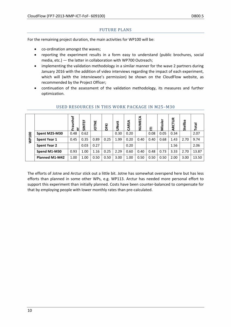
Spent M25-M30 0.48 0.62 0.30 0.20 0.08 0.05 0.34 2.07
Spent Year 1 0.45 0.35 0.89 0.25 1.99 0.20 0.40 0.40 0.68 1.43 2.70 9.74
Spent Year 2 0.03 0.27 0.20 1.56 2.06
Spend M1-M30 0.93 1.00 1.16 0.25 2.29 0.60 0.40 0.48 0.73 3.33 2.70 13.87
Planned M1-M42 1.00 1.00 0.50 0.50 3.00 1.00 0.50 0.50 0.50 2.00 3.00 13.50
The efforts of Jotne and Arctur stick out a little bit. Jotne has somewhat overspend here but has less
efforts than planned in some other WPs, e.g. WP113. Arctur has needed more personal effort to
support this experiment than initially planned. Costs have been counter-balanced to compensate for
that by employing people with lower monthly rates than pre-calculated.
D800.5 CloudFlow (FP7-2013-NMP-ICT-FoF- 609100)
11
2.2 WP110 — 1st wave of experiments
Start M01 End M24 Lead Fraunhofer
Participants SINTEF, JOTNE, DFKI, UNott, CARSA, NUMECA, ITI, Missler, ARCTUR, Stellba
OBJECTIVES (AS STATED IN GRANT AGREEMENT)
The aim of this work package is to act as an umbrella for the execution, assessment and validation of
the wave 1 experiments.
TASK 110.2: MONITORING OF THE EXECUTION OF EXPERIMENTS (AS STATED IN GRANT AGREEMENT)
This task will plan and monitor the process of execution of the experiments. The output of the
experiments has to be captured and reported. The partners involved in the application experiments
will be responsible for the execution of their corresponding experiments and the reporting.
TASKS ADDRESSED IN WP110, M25–M30
Task 110.2 “Monitoring of the Execution of Experiments” was supposed to end by M24 and the
evaluation of wave 1 experiments mostly happened on time. However, further improvements —
based on the outcome of the evaluation — were realised by various partners before the 2nd project
review in September 2015. These improvements have been overseen by the monitoring activities of
Task 110.2.
SIGNIFICANT RESULTS
In the reporting period the co-ordination and the preparation of the presentation of the wave 1
experiments’ results at the 2nd project review, as well as their successful demonstration at the review
in London, constitute the most significant results.
MAIN ACTIVITIES IN WP110, M25–M30
The outcome of the evaluation of the experiments of wave 1 was assessed and prioritized in order to improve the individual tool’s functionalities and usability as well as the CloudFlow infrastructure. The improvements have been successfully shown during the review in September 2015 in London. This required the coordination between all wave 1 partners. Not only the technical aspects have been progressed in this reporting period but also the business aspects, including the estimation of future business value as detailed in the individual per experiment reports and the last Periodic Progress Report (D800.4), whose finalization falls into the reporting period.
MILESTONES APPLICABLE TO WP110, M25–M30
None

CloudFlow (FP7-2013-NMP-ICT-FoF- 609100) D800.5
12
DEVIATION FROM PLANS
This work package was supposed to end by M24. Actually, the preparation for the 2nd project review
in M27 required some monitoring efforts as reported above.
DEVIATIONS FROM CRITICAL OBJECTIVES
None
CORRECTIVE ACTIONS
None
REFLECTION ON FUTURE PLANS FROM D800.4
In D800.4 we reported that we want to keep Stellba involved until the end of the project (and
beyond). For wave 3 we are planning an assessment of the 3rd version of the CloudFlow
infrastructure and Portal together with Stellba, dedicating some internal budget to Stellba for this
additional, not initially planned effort for Stellba.
FUTURE PLANS
We consider this work package as being closed and will handle additional activities which may
involve existing wave 1 partners as part of WP800.
USED RESOURCES IN THIS WORK PACKAGE IN M25–M30
WP
11
0 Fr
aun
ho
f
er
SIN
TEF
JOTN
E
DFK
I
UN
ott
CA
RSA
NU
MEC
A
ITI
Mis
sle
r
AR
CTU
R
Ste
llba
Tota
l
Spent M25-M30 0.10 0.07 0.17
Spent Year 1 0.50 0.50 0.87 1.00 0.49 0.50 0.25 0.40 0.69 2.04 7.24
Spent Year 2 1.00 1.00 0.18 2.51 0.50 0.25 2.34 7.78
Spend M1-M30 1.50 1.60 1.12 1.00 3.00 1.00 0.50 0.40 0.69 4.38 15.19
Planned M1-M42 1.80 1.60 0.30 1.50 3.00 1.00 0.50 0.50 0.30 2.00 12.50
The effort of Jotne, Missler and Arctur stick out a little bit. Missler has somewhat overspend here but
has less efforts than planned in some other WPs, e.g. WP111. Jotne has somewhat overspend here
but overall a balanced involvement w.r.t. plans. Arctur has needed more personal effort to support
the experiments than initially planned. Costs have been counter-balanced to compensate for that by
employing people with lower monthly rates than pre-calculated.

D800.5 CloudFlow (FP7-2013-NMP-ICT-FoF- 609100)
13
2.3 WP111 — CAD on the Cloud
Start M01 End M24 Lead Missler
Participants JOTNE, UNott, ARCTUR, Stellba
OBJECTIVES (AS STATED IN GRANT AGREEMENT)
The aim of this work package is to implement an application experiment for modelling services using
a tailored parametric CAD application on the CloudFlow infrastructure.
TASK 111.1: EXECUTION OF EXPERIMENTS (AS STATED IN GRANT AGREEMENT)
The list of CAD steps suitable for automation in the transformation of the surface model into a
volume model is manifold:
adding material thicknesses,
inserting struts or drill-holes,
adding roundings at edges between blade and hub / shroud, especially complicated at the
blade’s sharp trailing edge,
parametric design of the flange that connects Kaplan turbine blades to the hub,
adding a parameterized notch between the Kaplan blade and Kaplan flange,
parametric construction of a Kaplan hub and
parametric preparation of the finished runner model for the following structural simulations.
The subsequent structural simulations are usually carried out in just one blade channel (with
rotationally symmetric patches in circumferential direction). Taking advantage of the symmetry
accelerates the simulation runtime and simplifies the meshing but adds the task of cutting “one piece
of the cake” in CAD, which can be quite tricky and is a perfect task for automation. Given the
experiment’s constraints in time and effort, it will not be possible to automate all items of the above
list, so 2–3 of them will be chosen, based on expected benefit and ease of automation.
TASK 111.2: EXPERIMENT ASSESSMENT AND VALIDATION (AS STATED IN GRANT AGREEMENT)
This task will evaluate the execution process of the experiments. The results of the experiment have
been captured, post-processed, evaluated and reported in the Deliverable D111.1.

CloudFlow (FP7-2013-NMP-ICT-FoF- 609100) D800.5
14
TASKS ADDRESSED IN WP111, M25–M30
By M24 both tasks of the experiment were completed. However, work related to the experiment in
WP111 and WP200 has been addressed with a special focus on the review in September 2015 (M27)
and the use of Experiment 111 for tests of new developments of the CloudFlow infrastructure.
SIGNIFICANT RESULTS
In the period M25–M30 the following main results were achieved:
Stabilization of the software of the experiment.
Development of a new workflow to allow usage of the full CAD software on a virtual machine
on the Cloud (SAAS).
Successful live demonstration of the Experiment 111 workflow at the review in September
2015 (M27).
New developments of the CloudFlow infrastructure are as a general rule first tested on the
Experiment 111 workflow.
MAIN ACTIVITIES IN WP111, M25–M30
The main activities focussed on the preparation of the demonstration for the review. Missler
developed a new workflow to allow the usage of the generic CAD software on a virtual machine on
the cloud. This workflow will create a new business model based on SAAS.
MILESTONES APPLICABLE TO WP111, M25–M30
None
DEVIATION FROM PLANS
A new possibility, not scheduled within the CloudFlow project, has been added to use the CAD
software on a virtual machine on the cloud.
DEVIATIONS FROM CRITICAL OBJECTIVES
None
CORRECTIVE ACTIONS
None necessary
PROGRESS BEYOND THE STATE OF THE ART
This experiment allows the end user Stellba to optimize their design process of Kaplan blades and to
save time in the production of their turbines. It is possible to create such a turbine design by using
standard CAD functionalities, but it can take a long time and a lot of interactions to obtain the final
result. By using the dedicated Cloud application developed for this experiment, we can define a new
blade by performing just a few interactions. Before the experiment more than 20 operations were
D800.5 CloudFlow (FP7-2013-NMP-ICT-FoF- 609100)
15
necessary to design the full blade in the chosen example. In contrast, the new application that can be
used through the Cloud needs only 2 operations.
It is now possible to configure the CAD application with only the necessary functions for the design a
customer wants to carry out (drafting, rendering, surface modeller, volume modeller, etc.), starting
from a core CAD system and implementing it with plug-ins on-demand.
This new generic methodology is now in place and Missler — or any third party — can add and
deploy through the Cloud any add-ons or applications in an economic way.
REFLECTION ON FUTURE PLANS FROM D800.4
The user evaluation by Stellba, which was monitored by UNott, has been carried out on time. The
results now further steer the adaptation phase. This adaptation phase will continue after the end of
this experiment and even after the end of the project, according to the evolutions of the CloudFlow
infrastructure and the statement of the Competence Centre.
FUTURE PLANS
As the analysis of the evaluation results is completed, the results (usability issues, technology
readiness and areas for improvement) have been communicated to the involved partners and used
to improve the current application.
As the file format changed with the dedicated add-on information, at the moment it is necessary that
the add-on has already been launched to read an input file correctly. The next extension step for the
CAD application will be to implement functionalities to launch the necessary add-on automatically
when opening the file. This will be done after the end of the project.
An analysis has to be done to define the list of already existing applications that can be available on
the cloud.
The CAD software is not prepared to be a full web application. Some adaptations are necessary,
which have to be completed after the end of the project.
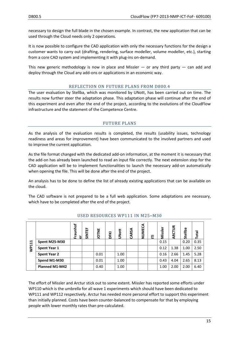
USED RESOURCES WP111 IN M25–M30
WP
11
1 Fr
aun
ho
f
er
SIN
TEF
JOTN
E
DFK
I
UN
ott
CA
RSA
NU
MEC
A
ITI
Mis
sle
r
AR
CTU
R
Ste
llba
Tota
l
Spent M25-M30 0.15 0.20 0.35
Spent Year 1 0.12 1.38 1.00 2.50
Spent Year 2 0.01 1.00 0.16 2.66 1.45 5.28
Spend M1-M30 0.01 1.00 0.43 4.04 2.65 8.13
Planned M1-M42 0.40 1.00 1.00 2.00 2.00 6.40
The effort of Missler and Arctur stick out to some extent. Missler has reported some efforts under
WP110 which is the umbrella for all wave 1 experiments which should have been dedicated to
WP111 and WP112 respectively. Arctur has needed more personal effort to support this experiment
than initially planned. Costs have been counter-balanced to compensate for that by employing
people with lower monthly rates than pre-calculated.

CloudFlow (FP7-2013-NMP-ICT-FoF- 609100) D800.5
16
2.4 WP112 — CAM on the Cloud
Start M01 End M24 Lead Missler
Participants UNott, ARCTUR, Stellba
OBJECTIVES (AS STATED IN GRANT AGREEMENT)
The aim of this work package is to implement an application experiment for manufacturing services
using a CAM application on the CloudFlow infrastructure.
TASK 112.1: EXECUTION OF EXPERIMENTS (AS STATED IN GRANT AGREEMENT)
Based on the experiment to be executed all input data (parameters, movement laws), models,
configurations, and tools needed for computing the model will be defined. The proposed experiment
will be executed on the target infrastructure. The end user will define parameters and movement
laws. The model will be computed using the CAM on the Cloud service and results will be exported.
At the end a post-processor will generate the required ISO code for a dedicated milling machine.
TASK 112.2: EXPERIMENT ASSESSMENT AND VALIDATION (AS STATED IN GRANT AGREEMENT)
This task will evaluate the execution process of the experiments. The results of the experiment have
been captured, post-processed, evaluated and reported in the Deliverable D112.1.
TASKS ADDRESSED IN WP112, M25–M30
By M24 both tasks of the experiment were completed. However, work related to the experiment in
WP112 and WP200 has been addressed with a special focus on the review in September 2015 (M27)
and the use of Experiment 112 for tests of new developments of the CloudFlow infrastructure.
SIGNIFICANT RESULTS
In the period M25–M30 the following main results were achieved:
Stabilization of the software of the experiment.
Successful live demonstration of the Experiment 112 workflow at the review in September
2015 (M27).
The first version of this experiment has been demonstrated live at the Project Review,
including
o using a dedicated Cloud user interface,
o uploading data,
o launching the computation and
o getting the resulting CAM tool path.
A dedicated document has been written explaining how to use the CAM in the Cloud
application.
New developments of the CloudFlow infrastructure are as a general rule first tested on the
Experiment 112 workflows.
D800.5 CloudFlow (FP7-2013-NMP-ICT-FoF- 609100)
17
MAIN ACTIVITIES IN WP112, M25–M30
The main activities focussed on the preparation of the demonstration for the review.
MILESTONES APPLICABLE TO WP112, M25–M30
None
DEVIATION FROM PLANS
None
DEVIATIONS FROM CRITICAL OBJECTIVES
None
CORRECTIVE ACTIONS
None necessary
PROGRESS BEYOND THE STATE OF THE ART
To produce a part in a CAM system, it is necessary to define and compute all steps of the process one
by one. Some of these steps or operations can take a long time to compute and can be launched only
one at a time. This time can be reduced by using a more powerful machine and by parallelizing this
process and the algorithms inside.
The CAM experiment yielded good results in terms of performance using the Cloud, as it can work
with one or more ‘big machines’ on the Cloud. All operations defined to produce the part can be
‘transported’ to the Cloud, where it can be computed in parallel using all the computing power
provided. The necessary computation time for one operation on one VM has been decreased by a
factor of 3.
The main bottleneck of the process remains to provide the results on the local system as it can take
some time just to download all the resulting data from the Cloud. Our tests were carried out only for
one process, raising the interesting issue of launching several processes, allowing the end user to
work on his local computer and prepare other parts in the meantime.
REFLECTION ON FUTURE PLANS FROM D800.4
The user evaluation by Stellba, monitored by UNott, has been carried out on time. The results now
further steer the adaptation phase. This adaptation phase will continue after the end of this
experiment, according to the evolutions of the CloudFlow infrastructure.
FUTURE PLANS
We will continue to use this experiment as a test case for new functionality in the CloudFlow
infrastructure, including exploitation of HPC-resources.

CloudFlow (FP7-2013-NMP-ICT-FoF- 609100) D800.5
18
The results of Experiment 112 will be used as background in the new FoF project CAxMan
(September 2015 – August 2018) addressing design and simulation for additive manufacturing.
Missler plans to make the CAM share of the workflow of Experiment 112 commercially available in
the Cloud as part of the cooperation in the CloudFlow Competence Centre.
USED RESOURCES WP112 IN M25–M30
WP
11
2 Fr
aun
ho
f
er
SIN
TEF
JOTN
E
DFK
I
UN
ott
CA
RSA
NU
MEC
A
ITI
Mis
sle
r
AR
CTU
R
Ste
llba
Tota
l
Spent M25-M30 0.35 0.20 0.55
Spent Year 1 0.10 1.26 0.70 2.06
Spent Year 2 1.00 0.67 2.78 2.30 6.75
Spend M1-M30 1.00 1.12 4.04 3.20 9.36
Planned M1-M42 1 1 2 2 6.00
The effort of Missler and Arctur stick out to some extent. Missler has reported some efforts under
WP110 which is the umbrella for all wave 1 experiments which should have been dedicated to
WP111 and WP112 respectively. Arctur has needed more personal effort to support this experiment
than initially planned. Costs have been counter-balanced to compensate for that by employing
people with lower monthly rates than pre-calculated.

D800.5 CloudFlow (FP7-2013-NMP-ICT-FoF- 609100)
19
2.5 WP113 — CFD on the Cloud
Start M01 End M24 Lead NUMECA
Participants Jotne, UNott, Arctur, Stellba
OBJECTIVES (AS STATED IN GRANT AGREEMENT)
This experiment addresses CFD analyses in an engineering workflow on the CloudFlow infrastructure.
TASK 111.1: EXECUTION OF EXPERIMENTS (AS STATED IN GRANT AGREEMENT)
The experiment starts from CAD input files. Standard representation of CAD data shall be used (ISO
10303 AP203, AP214, AP242). Support for CAD vendor formats must also be considered. This initial
data usually resides on the user’s local network, where the CAD system resides. CAD data is used as
input for the mesh generation tool. The setup of the mesh generation, requiring possibly many
manual operations and visualisation, is performed on the local network. The mesh generation,
requiring large shared memory machines, is performed on the Cloud. This involves a transfer of the
tessellated geometry over the Internet, in a fully secure way, as well as a transparent launch of the
mesher on the Cloud.
The result of the mesh generation is a file containing the mesh. Standardized representation of this
mesh and boundary conditions (ISO 10303 AP209) must be used to enable smooth data transfer
between heterogeneous software in the CloudFlow environment. During the mesh generation
process, which can last for several hours for large meshes, a monitoring of the generation is
foreseen, through a web browser.
Next, the setup of the CFD simulation is performed, again on the local user’s machine. The input to
the solver is the mesh previously generated, together with the boundary conditions and initial
conditions. In the setup process it should be avoided, if possible, to copy the mesh back and forth,
saving time and increasing the benefit. The solver service is launched on the Cloud according to the
resources requested by the user. A monitoring of the solver convergence will be available through a
thin client or a web browser to allow the user to control the process.
TASK 111.3: EXPERIMENT ASSESSMENT AND VALIDATION (AS STATED IN GRANT AGREEMENT)
This task evaluates the execution process of the experiments. The results of the experiment have
been captured, post-processed, evaluated and reported in the Deliverable D111.1.

CloudFlow (FP7-2013-NMP-ICT-FoF- 609100) D800.5
20
TASKS ADDRESSED IN WP113, M25–M30
The major work on this experiment has been completed by M24, as foreseen in the work plan.
Special focus has been addressed on the September review (M27), for which the experiments, basic
CFD workflow and the parametric study, have been refined and improved.
SIGNIFICANT RESULTS
In the period M25–M30 the following main results were achieved:
Stabilization of the software of the experiment.
Improvement of the robustness of the parametric study. Compared to previously obtained
results, many more CFD runs, corresponding to different sets of parameters, have been able
to converge until the end.
This has allowed the Hill chart to be generated by Stellba, which was the main objective of
the study.
MAIN ACTIVITIES IN WP113, M25–M30
The main activities focussed on the preparation of the demonstration for the review and on the
finalisation of the parametric study workflow.
MILESTONES APPLICABLE TO WP113, M25–M30
None
DEVIATION FROM PLANS
The parametric study was not initially foreseen in the DoW. However, considering its importance to
the end user Stellba, it has been planned and successfully conducted until the end.
As of today, it is still easier for an end user to prepare a CFD project (mesh parameters, solver
parameters) on a local workstation, before executing the workflow on the CloudFlow platform.
DEVIATIONS FROM CRITICAL OBJECTIVES
None
CORRECTIVE ACTIONS
None
PROGRESS BEYOND THE STATE OF THE ART
Thanks to the CloudFlow platform and the developed workflows, industrial use of advanced CFD is
now possible on the Cloud, at the HPC level.
D800.5 CloudFlow (FP7-2013-NMP-ICT-FoF- 609100)
21
Users can now fully visualize and generate their meshes in their web browser using remote execution
on the cloud, allowing a use of great resources and making the generation and the CFD simulation
much faster than on a local desktop.
In addition, users can now run, in an automated manner, hundreds of mesh generations and CFD
simulations, saving hours of manual operations.
The use of PLM as a means to store and exchange data between heterogeneous tools is also seen as
a major step forward towards advanced engineering workflows on the Cloud.
REFLECTION ON FUTURE PLANS FROM D800.4
In the Section “Future plans” of Deliverable D800.4, it was stated: “The priority is now on
industrialising and exploiting the developments so as to make them fully usable for industrial use, in
terms of quality and usability. The adaptation of the existing workflow will be pursued to match the
new advances in the CloudFlow infrastructure.” As explained in the previous section “Progress
beyond state of the art”, these goals have been achieved to a large extent.
FUTURE PLANS
The last objective within WP113 is to bring the workflows to the new CloudFlow Portal.
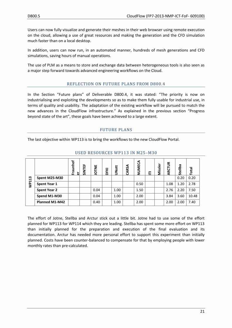
USED RESOURCES WP113 IN M25–M30
WP
11
3 Fr
aun
ho
f
er
SIN
TEF
JOTN
E
DFK
I
UN
ott
CA
RSA
NU
MEC
A
ITI
Mis
sle
r
AR
CTU
R
Ste
llba
Tota
l
Spent M25-M30 0.20 0.20
Spent Year 1 0.50 1.08 1.20 2.78
Spent Year 2 0.04 1.00 1.50 2.76 2.20 7.50
Spend M1-M30 0.04 1.00 2.00 3.84 3.60 10.48
Planned M1-M42 0.40 1.00 2.00 2.00 2.00 7.40
The effort of Jotne, Stellba and Arctur stick out a little bit. Jotne had to use some of the effort
planned for WP113 for WP114 which they are leading. Stellba has spent some more effort on WP113
than initially planned for the preparation and execution of the final evaluation and its
documentation. Arctur has needed more personal effort to support this experiment than initially
planned. Costs have been counter-balanced to compensate for that by employing people with lower
monthly rates than pre-calculated.

CloudFlow (FP7-2013-NMP-ICT-FoF- 609100) D800.5
22
2.6 WP114 — PLM on the Cloud
Start M01 End M24 Lead JOTNE
Participants Fraunhofer, UNott, ARCTUR, Stellba
OBJECTIVES (AS STATED IN GRANT AGREEMENT)
This experiment addresses the necessary product lifecycle management (PLM) capabilities in an
engineering workflow on the CloudFlow infrastructure.
TASK 114.1: EXECUTION OF EXPERIMENTS (AS STATED IN GRANT AGREEMENT)
Partners will provide the needed data for the PLM system and the requirements for the resulting
behaviour will be specified. All necessary input data, models, configurations, and tools will be
defined. In preparation for the complete example, the individual processing steps will be executed
and tested separately. The entire example workflow will be executed by simulation and PLM experts.
TASK 114.2: EXPERIMENT ASSESSMENT AND VALIDATION (AS STATED IN GRANT AGREEMENT)
This task will evaluate the execution process of the experiments. The results of the experiment will
be captured, post-processed, evaluated and reported.
TASKS ADDRESSED IN WP114, M25–M30
By M24 both tasks of the experiment were completed. However, work related to this experiment
was addressed in WP100, WP110, and WP200–WP700 with special focus on
the review in September 2015 (M27) and
the use of Experiment 114 for tests of new developments of the CloudFlow infrastructure.
SIGNIFICANT RESULTS
Significant results in other work packages related to WP114 in the period M25–M30 were:
Stabilization of the PLM and visualization software of the experiment.
Deficiencies discovered during the final evaluation and corrective actions as listed in detail in
Appendix 3: “Usability Evaluation” of D114.1 were implement in time for the second project
review in September 2015.
Development of PLM subscription/notification was completed on the server-side.
Successful live demonstration of the Experiment 114 workflow at the M24 review.
MAIN ACTIVITIES IN WP114, M25–M30
In the M24 PPR the following issues were recorded during evaluation of the experiment by the
project partners (see D114.1 Appendix 3), which were planned to be implemented before the M24
review in September 2015. The following was performed from M24–M27 (date of the review):
D800.5 CloudFlow (FP7-2013-NMP-ICT-FoF- 609100)
23
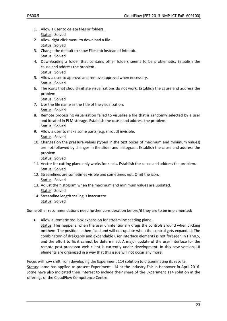
1. Allow a user to delete files or folders.
Status: Solved
2. Allow right click menu to download a file.
Status: Solved
3. Change the default to show Files tab instead of Info tab.
Status: Solved
4. Downloading a folder that contains other folders seems to be problematic. Establish the
cause and address the problem.
Status: Solved
5. Allow a user to approve and remove approval when necessary.
Status: Solved
6. The icons that should initiate visualizations do not work. Establish the cause and address the
problem.
Status: Solved
7. Use the file name as the title of the visualization.
Status: Solved
8. Remote processing visualization failed to visualise a file that is randomly selected by a user
and located in PLM storage. Establish the cause and address the problem.
Status: Solved
9. Allow a user to make some parts (e.g. shroud) invisible.
Status: Solved
10. Changes on the pressure values (typed in the text boxes of maximum and minimum values)
are not followed by changes in the slider and histogram. Establish the cause and address the
problem.
Status: Solved
11. Vector for cutting plane only works for z-axis. Establish the cause and address the problem.
Status: Solved
12. Streamlines are sometimes visible and sometimes not. Omit the icon.
Status: Solved
13. Adjust the histogram when the maximum and minimum values are updated.
Status: Solved
14. Streamline length scaling is inaccurate.
Status: Solved
Some other recommendations need further consideration before/if they are to be implemented:
Allow automatic tool box expansion for streamline seeding plane.
Status: This happens, when the user unintentionally drags the controls around when clicking
on them. The position is then fixed and will not update when the control gets expanded. The
combination of draggable and expandable user interface elements is not foreseen in HTML5,
and the effort to fix it cannot be determined. A major update of the user interface for the
remote post-processor web client is currently under development. In this new version, UI
elements are organized in a way that this issue will not occur any more.
Focus will now shift from developing the Experiment 114 solution to disseminating its results.
Status: Jotne has applied to present Experiment 114 at the Industry Fair in Hannover in April 2016.
Jotne have also indicated their interest to include their share of the Experiment 114 solution in the
offerings of the CloudFlow Competence Centre.

CloudFlow (FP7-2013-NMP-ICT-FoF- 609100) D800.5
24
MILESTONES APPLICABLE TO WP114, M25–M30
None
DEVIATION FROM PLANS
The work package did not end as planned in M24, but continued until M27 to resolve software and
data issues related to the experiment demonstration at the project year 2 review in M27.
DEVIATIONS FROM CRITICAL OBJECTIVES
None
CORRECTIVE ACTIONS
None necessary
PROGRESS BEYOND THE STATE OF THE ART (FROM M24 PPR)
The statements in the WP114 section of D800.4 still apply.
REFLECTION ON FUTURE PLANS FROM D800.4
See the list of updates in the section “Main activities in WP114”, above. These were done in
reflection of the future plans stated in D800.4.
FUTURE PLANS
The team will continue to use this experiment as a test case for new functionality in the CloudFlow
infrastructure, including exploitation of HPC-resources.
The results of Experiment 114 will be used as background in the new FoF project CAxMan
(September 2015 – August 2018) addressing design and simulation for additive manufacturing.
Jotne plans to make the PLM share of the Experiment 114 workflow commercially available in the
Cloud as part of the cooperation in the CloudFlow Competence Centre.

D800.5 CloudFlow (FP7-2013-NMP-ICT-FoF- 609100)
25
USED RESOURCES WP114 IN M25–M30 W
P1
14
Frau
nh
of
er
SIN
TEF
JOTN
E
DFK
I
UN
ott
CA
RSA
NU
MEC
A
ITI
Mis
sle
r
AR
CTU
R
Ste
llba
Tota
l
Spent M25-M30 0.10 0.10
Spent Year 1 1.14 0.80 1.94
Spent Year 2 0.60 1.27 1.00 3.07 1.40 7.34
Spend M1-M30 0.60 1.27 1.00 4.21 2.30 9.38
Planned M1-M42 0.60 0.40 1.00 2.00 2.00 6.00
The effort of Jotne and Arctur stick out a little bit. Jotne is leading this WP and it turned out to be
more time-consuming than initially planned. Jotne drew some of the effort from WP113 to
compensate for that. Still, data integration between WP113 and WP114 has been achieved to a
reasonable extend. Arctur has needed more personal effort to support this experiment than initially
planned. Costs have been counter-balanced to compensate for that by employing people with lower
monthly rates than pre-calculated.

CloudFlow (FP7-2013-NMP-ICT-FoF- 609100) D800.5
26
2.7 WP115 — Systems Simulation on the Cloud
Start M01 End M24 Lead ITI
Participants Fraunhofer, UNott, ITI, ARCTUR, Stellba
OBJECTIVES (AS STATED IN GRANT AGREEMENT)
The aim of this work package is to implement an application experiment for defining, executing and
evaluating systems simulation of a CAM machine on the CloudFlow infrastructure.
Note: As stated in D800.2 (Section 3.7 — Deviation from plans), the system simulation model for this
experiment is now a complete water power plant. The power plant model is used for the pre-
dimensioning of components and the simulation of critical conditions. The overall objective has not
changed, because this experiment is not linked to a particular system simulation model.
TASK 115.1: EXECUTION OF EXPERIMENTS (AS STATED IN GRANT AGREEMENT)
Models, configurations, and additional data needed for experiment execution will be defined and
documented. The requirements for the target infrastructure will be specified. The infrastructure
provider will prepare the execution environment and will provide access to resources for end users.
Test and usage scenarios will be described. The proposed experiment will be executed on the target
infrastructure.
TASK 115.2: EXPERIMENT ASSESSMENT AND VALIDATION (AS STATED IN GRANT AGREEMENT)
This task will evaluate the execution process of the experiments. The results of the experiment will
be captured, post-processed, evaluated and reported.
ACTIVITIES ADDRESSED IN THIS WORK PACKAGE, M25–M30
Both tasks of the experiment were conducted, and work related to the experiment in WP100,
WP115, and WP300–WP700 has been addressed with a special focus on the review in September
2015 (M27) and the comments of the final evaluation. The main task was to improve and optimize
the execution of the experiment.
SIGNIFICANT RESULTS, M25–M30
The main results of this work package during the reporting period are the implementation of the
following issues of the final evaluation:
Estimation of the processing time by displaying the resulting number of simulation runs for a
simulation task. This avoids accidentally defining too many simulation runs.
The user can trace the progress of simulation calculations.
Improved user interface of applications.
Stabilization of services and applications.

D800.5 CloudFlow (FP7-2013-NMP-ICT-FoF- 609100)
27
Demonstration of the workflow at the M24 review.
Furthermore, the business model has been detailed in cooperation with CARSA.
MAIN ACTIVITIES IN THIS WORK PACKAGE, M25–M30
The main activities focused on the extension, optimization and stabilization of services and
applications of this experiment.
The most visible improvement for the end user is the improved layout. The column based layout
allows for a better use of the space at the screen.
A main implementation task was the prediction and estimation of calculation time. The user gets
informed about the number of simulations for parameter studies before he starts a simulation task.
The monitoring information during the simulation run (provided by the GridWorker) is displayed to
the user. This is not only the number of completed, running and remaining simulations, but includes
also an estimate of the remaining simulation time. The estimate is based on the already completed
simulations.
Another important implementation task was the optimization of the service. The work focused on a
reduced accessing to the SWIFT storage by reorganizing the handling of models and simulation
results.
The experiment revised and created a more detailed business model (WP600) in cooperation with
CARSA.
ITI presented the results of CloudFlow at the 18th ITI Symposium 2015 (November 10–11, 2015).
MILESTONES APPLICABLE TO WP115, M25–M30
None
DEVIATION FROM PLANS
None
DEVIATIONS FROM CRITICAL OBJECTIVES
None
CORRECTIVE ACTIONS
None necessary
PROGRESS BEYOND THE STATE OF THE ART (FROM M24 PPR)
The FMI standard defines a vendor neutral standard C-Interface (Functional Mock-up Interface) and
offers the possibility to run simulation models from different tools. Modules providing an FMI
compliant interface are called Functional Mock-up Units (FMU). The workflow of this experiment

CloudFlow (FP7-2013-NMP-ICT-FoF- 609100) D800.5
28
enables the user to upload an FMU, to define the simulation task (parameter values for the model),
to run the simulations in the Cloud and to review the simulation results.
The implementation of Experiment 115 provides features beyond the state of the art in the following
fields:
Data management
The implemented workflow stores the model independently from the simulation task. This
allows the user to upload the model once but use the model for several simulation tasks.
The Cloud data management organizes the link between the model, the simulation task and
the simulation results. This allows the end user to compare the simulation tasks (and their
results) of a model.
Accessibility
The complete user interface of the workflow is HTML based. This enables users to access
the service from any platform that provides an HTML browser. The central storage in the
Cloud makes it easy to share the simulation data with other users.
Usability
The system simulation service in Experiment 115 allows including a picture in the FMU which
is shown during the workflow (model selection and simulation task definition). ITI extended
the FMU generation of SimulationX and added a screenshot of the model structure. This
facilitates the selection of the model and visualizes the relationship between parameters
and model elements during the simulation task definition. The added picture does not affect
the FMI compatibility of the FMU, and the system simulation service handles also FMUs
without pictures.
Definition of parameter studies
The option to scale up resources on-demand in the Cloud offers the possibility to
dynamically acquire the needed compute resources and to speed up the simulation of
parameter studies. The task definition enables the user to define parameter ranges and to
run the resulting simulation calculations in parallel Cloud nodes.
REFLECTION ON FUTURE PLANS FROM D800.4
The plans to implement the progress indicator for simulation calculation could be fullfilled, and the
storage service could be integrated completely. The recommendations of the final evaluation have
been taken into account.
FUTURE PLANS
In future versions of the workflow, users will be able to define time outs per simulation task and per
simulation run. Thus, the costs can be reliably limited.
The improved support of big simulation results is the prerequisite for efficient exploration and
analysis of simulation data. The main objective is the reduction of the data transfer between Cloud
storage and simulation service. This can be achieved by a more structured storage of simulation
results.
D800.5 CloudFlow (FP7-2013-NMP-ICT-FoF- 609100)
29
USED RESOURCES, M25–M30 W
P1
15 Fr
aun
ho
f
er
SIN
TEF
JOTN
E
DFK
I
UN
ott
CA
RSA
NU
MEC
A
ITI
Mis
sle
r
AR
CTU
R
Ste
llba
Tota
l
Spent M25-M30 0.20 0.10 0.30
Spent Year 1 0.13 0.95 0.60 1.68
Spent Year 2 0.47 1.00 1.80 3.16 1.30 7.73
Spend M1-M30 0.60 1.00 2.00 4.11 2.00 9.71
Planned M1-M42 0.60 1.00 2.00 0.20 2.00 2.00 7.80
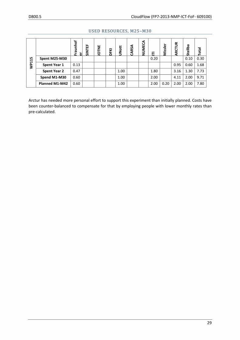
Arctur has needed more personal effort to support this experiment than initially planned. Costs have
been counter-balanced to compensate for that by employing people with lower monthly rates than
pre-calculated.
CloudFlow (FP7-2013-NMP-ICT-FoF- 609100) D800.5
30
2.8 WP116 — Point cloud vs CAD Comparison on the Cloud
Start M01 End M24 Lead SINTEF
Participants UNott, ARCTUR, Stellba
OBJECTIVES (AS STATED IN GRANT AGREEMENT)
The aim of this work package is to implement on the CloudFlow infrastructure an application
experiment where the actual shapes of water turbine blades (Kaplan, Francis) are compared to their
nominal shapes as defined by CAD.
TASK 116.1: EXECUTION OF EXPERIMENTS (AS STATED IN GRANT AGREEMENT)
Models, configurations, and additional data needed for experiment execution will be refined and
documented. The requirements for the target infrastructure will be specified. The infrastructure
provider will prepare the execution environment and will provide access to resources for end users.
Test and usage scenarios will be described. The proposed experiment will be executed on the target
infrastructure. The end users involved in the application experiment will be responsible for the
execution.
TASK 116.2: EXPERIMENT ASSESSMENT AND VALIDATION (AS STATED IN GRANT AGREEMENT)
This task will evaluate the execution process of the experiments. The results of the experiment will
be captured, post-processed, evaluated and reported.
TASKS ADDRESSED IN WP116, M25–M30
By M24 Task 116.1 Execution of experiments was completed, while in Task 116.2 Experiment
Assessment and Validation only the final polishing of the report from deliverable D116.1 remained.
D116.1 proposed a number of suggestions/improvements to the workflow of Experiment 116. These
have all been addressed using the resources from work packages for technical development (WP200,
WP300, WP400, and WP500). Details on these developments can be found in dedicated subsections
further down in this section, addressing WP116 in a separate subsection with the name “Reflection
on Future Plans from D800.4”. Work on the business model of Experiment 116 has been addressed in
WP600.
SIGNIFICANT RESULTS
Significant results in other work packages related to WP116 in the period M25–M30 were:
Adjustment of the workflow taking the suggestions/recommendations in D116.1 into
account, with details in the subsection “Reflection on Future Plans from D800.4”.
Stabilization of the software of the experiment.
Improvements of the STEP reader.

D800.5 CloudFlow (FP7-2013-NMP-ICT-FoF- 609100)
31
Successful live demonstration of the Experiment 116 workflow at the M24 review, as well as
at SIAM Geometric Design (Salt Lake City in October 2015), and Forum for Additive and
Subtractive Manufacturing in Norway in November 2015.
New developments of the CloudFlow infrastructure are as a general rule first tested on the
Experiment 116 workflow.
MAIN ACTIVITIES IN WP116, M25–M30
The work package has ended as stated above.
MILESTONES APPLICABLE TO WP116, M25–M30
None
DEVIATION FROM PLANS
The final polishing of D116.1 was finished on July 21, 2015, a delay of 21 days. The work package was
thus ending 21 days later than planned.
DEVIATIONS FROM CRITICAL OBJECTIVES
None
CORRECTIVE ACTIONS
None necessary
PROGRESS BEYOND THE STATE OF THE ART (FROM M24 PPR)
Registration of CAD models and point clouds are addressed in a number of academic papers including
Changmin Kim, Joohyuk Lee, Minwoo Cho, Changwan Kim Pages 917–922 (2011 Proceedings of the
28th ISARC, Seoul, Korea), where point clouds are registered with respect to a tessellation of the CAD
model. Experiment 116 bases the registration on the exact CAD geometry without a quality reducing
tessellation step. As far as we know, registration of point clouds with respect to CAD models is new
as a Cloud service.
Software solutions for the registration of point clouds and CAD models are usually integrated as part
of software suites around metrology solutions. These solutions are consequently closely linked to
metrology solutions including the measurement devices. The use of point clouds in CAD systems is
focused on the creation of CAD models from point clouds not on comparing produced parts with the
nominal CAD model. Experiment 116 offers a solution that is independent from metrology devices as
a Cloud solution. As Experiment 116 is based on ISO STEP 10303 it is fully interoperable with CAD
systems.
In the Tinia remote rendering framework an algorithm was implemented for automatic proxy model
generation in a client/server remote rendering setup. A proxy model is a lightweight version of a high
resolution 3D model that is cheaper to render and to transfer. In our framework it is automatically
derived from the main model. The client only assumes the availability of WebGL and JavaScript. The
server makes use of OpenGL and a web server. When the rate of received server-rendered images

CloudFlow (FP7-2013-NMP-ICT-FoF- 609100) D800.5
32
deteriorates, the client renders the proxy model, which is computed from depth buffers bundled
with rendered images from the server. This algorithm allows complex CAD models to be visualised
with a high degree of interactivity on lightweight clients even over a low bandwidth network.
REFLECTION ON FUTURE PLANS FROM D800.4
In the M24 PPR the following were planned to be implemented before the M24 review in September
2015.
15. Add additional information on the screenshot regarding acceptable file types.
Status: Solved
16. Change the heading for “Specify output file name”.
Status: Solved
17. Reposition button related to info on TINIA.
Status: Solved
18. Improve information for “Visualisation Configuration”.
Status: Solved
19. Improve instruction given once a user has completed manual registration.
Status: Solved — Option is removed.
20. Add missing explanation for meaning of the summary results.
Status: Solved
21. Improve function for measurement units text box.
Status: Solved
Some other recommendations need further considerations before/if they are to be implemented:
Provide meaningful feedback to the user during conversion of STEP files. Conversion of files
can take longer time than expected. We will therefore consider changing the service from
synchronous to asynchronous in order to provide better status messages to the user.
Status: Progress bar added
Some functionality has been added for testing purposes and will be removed.
Possibility to skip registration will be removed.
Status: Option is removed
We will continue to use this experiment as a test case for new functionality in the CloudFlow
infrastructure, including exploitation of HPC-resources.
Status: The experiment is central with respect to the continued testing of the infrastructure.
SINTEF plans to make the workflow of Experiment 116 commercially available in the Cloud as
part of the cooperation in the CloudFlow Competence Centre.
Status: The plan is still valid
The results of Experiment 116 will be used as background in the new FoF project CAxMan
(September 2015 – August 2018) addressing design and simulation for additive manufacturing.
Status: The experiment workflow will be the primarily example of workflow implementation in
CAxMan.

D800.5 CloudFlow (FP7-2013-NMP-ICT-FoF- 609100)
33
FUTURE PLANS
We will continue to use this experiment as a test case for new functionality in the CloudFlow
infrastructure, including exploitation of HPC-resources.
SINTEF plans to make the workflow of Experiment 116 commercially available in the Cloud as part of
the cooperation in the CloudFlow Competence Centre.
The results of Experiment 116 will be used as background in the new FoF project CAxMan
(September 2015 – August 2018), addressing design and simulation for additive manufacturing.
USED RESOURCES WP116 IN M25–M30
WP
11
6 Fr
aun
ho
f
er
SIN
TEF
JOTN
E
DFK
I
UN
ott
CA
RSA
NU
MEC
A
ITI
Mis
sle
r
AR
CTU
R
Ste
llba
Tota
l
Spent M25-M30 0.10 0.10
Spent Year 1 0.85 1.00 1.85
Spent Year 2 1.40 1.00 2.88 1.30 6.58
Spend M1-M30 1.40 1.00 3.73 2.40 8.53
Planned M1-M42 1.40 1.00 2.00 2.00 6.40
Arctur has needed more personal effort to support this experiment than initially planned. Costs have
been counter-balanced to compensate for that by employing people with lower monthly rates than
pre-calculated.

CloudFlow (FP7-2013-NMP-ICT-FoF- 609100) D800.5
34
2.9 WP120 — 2nd wave of experiments
Start M10 End M30 Lead Fraunhofer
Participants SINTEF, Jotne, DFKI, UNott, CARSA, ARCTUR
OBJECTIVES (AS STATED IN GRANT AGREEMENT)
The aim of this work package is to handle all activities related to wave 2 experiments in a focused
and consistent manner. This covers:
defining selection criteria and the Open Call 1 text,
publishing Open Call 1 and promoting it in the target communities,
expert evaluator selection and briefing,
extracting the imposed requirements towards CloudFlow,
assessment of proposals, prioritization and selection,
internal review and support for consensus meetings,
accompanying/monitoring the execution of experiments,
accompanying/monitoring the assessment and validating of experiments.
TASK 120.3: MONITORING OF THE EXECUTATION OF EXPERIMENTS (AS STATED IN GRANT AGREEMENT)
This task will plan and monitor the process of execution of the experiments. The output of the
experiments has to be captured and reported. The partners involved in the application experiments
will be responsible for the execution of their corresponding experiments and the reporting.
TASKS ADDRESSED IN THIS WORK PACKAGE, M25–M30
The focus of the work in WP120 in M25–M30 has been on Task 120.3 Monitoring of the Execution of
Experiments. This has included remote interim evaluation sessions to check progress against
requirements, the development of business models and specific extensions to the CloudFlow
infrastructure, which have been implemented for the experiments of 2nd wave.
The other tasks of this WP (Task 120.1 Call Specification, Publication, and Experiment Selection and
Task 120.2 Experiment Requirements Analysis) are already completed and have been reported on in
previous deliverables.
SIGNIFICANT RESULTS
The main results of this work package are summarized in the following list:
Interim evaluation sessions including the assessment of each experiment against the
requirements
Assistance in designing and implementing a concrete business model for each experiment

D800.5 CloudFlow (FP7-2013-NMP-ICT-FoF- 609100)
35
Active support of second wave partners to integrate their experiments into the CloudFlow
infrastructure
Integration of two new Cloud / High Performance Computing Centres into the CloudFlow
infrastructure
Adaptations/Improvements on Workflow Manager, Workflow Editor, and the Portal after the
feedbacks received during integration of second wave experiments.
A code camp from 25th to 26th November 2015 was organized in Dresden to answer second
wave partner questions and provide instant support for implementing missing components
and for optimizing workflows used in second wave experiments.
The remote post-processing service (RPP) has been extended to support the data
representations and file formats used by the second wave experiments. Additional
functionality has been added to RPP in order to provide the flexibility needed to handle the
use cases of the different experiments.
The 2D charts generation service is used by Experiment 125 for monitoring the status of their
simulations by visualizing residuals and convergence rates.
For local visualizations of the production plant in Experiment 122, a web application has been
developed. The application dynamically loads all content and shows an interactive animation
of the optimized production configuration.
Supporting the partners of 2nd wave experiments (e.g. BioReactor, SIMCASE, Compressor,
EDA) to find an experiment setup which is suitable for Cloud and/or HPC compute back ends
Assistance was given to map the DoE (design of experiment) challenges to the features
provided by the GridWorker Generic Simulation Service
MAIN ACTIVITIES IN THIS WORK PACKAGE, M25–M30
Regarding business models, CARSA has been assisting 2nd wave partners in designing and implementing a concrete business model for each experiment, basically through Task 120.3: Monitoring of the Execution of Experiments. In this respect we followed the next list of activities (5-step methodology):
1. Analysis of the organization’s Current Business Model through filling a pre-defined
questionnaire.
2. Analysis of the current vs. new Cloud-Based Business Model, defining the exploration
concepts to be tested for each Osterwalder block, through an audio conference or face-to-
face meeting.
3. Definition of a Detailed Revenue Stream (charging/invoicing options and prices) associated
to the new Cloud-Based Business Model as well as the eventual simplification into a
concrete Subscription Type (time based, usage based, flexible) aiming at the experiment
running under the CloudFlow Portal.
4. Application of the Customer Development method for the theoretical Cloud-Based Business
Model validation.
5. Final Evaluation and Experience Review on the Cloud-Based Business Model defined and
tested during the experiment.
We have covered all 5 stages and the main results are the following (detailed information will be provided in the next deliverable V3 of CloudFlow infrastructure, month 36):
CloudFlow (FP7-2013-NMP-ICT-FoF- 609100) D800.5
36
EDA Experiment (WP121) In the specific case of Helic for the EDA experiment the two-stage approach will be the following:
1st stage: Helic has simplified the full approach and has basically followed the “on-demand” model. The cost of the application for the customer is 200 euro / core-hour.
2nd stage: Helic is interested in implementing also an “on-demand” model with a price variable depending on the complexity of the customer project.
Plant Simulation and Optimization Experiment (WP122) In the specific case of TTS for the Plant Simulation and Optimization experiment the two-stage approach will be the following:
1st stage: TTS has simplified the full approach and has basically followed the “on-demand” model. The cost of the application for the customer is 115 euro / core-hour.
2nd stage: TTS is also interested in implementing and keeping the current licensing model.
SIMCASE Experiment (WP123) In the case of SimAssist it is not so much reasonable to follow the on-demand model as there should be a minimum usage and it is based more on storage than on computing. The model should be “time based”. Thus, in the specific case of SimPlan for the SIMCASE experiment the two-stage approach will be the following:
1st stage: SimPlan is providing the customer access to the cloud application in a monthly basis. The cost of the application for the customer is 150 euro / user-month. However, SimPlan is also open to offer an “on-demand” model with a price of 6 euro/ core-hour
2nd stage: SimPlan is interested in implementing also an annual subscription or flat rate for 1 800 euro user/year for customers requiring a long time service usage. Compressor Experiment (WP124) In the specific case of Capvidia for the Compressor experiment the two-stage approach will be the following:
• 1st stage: Capvidia has simplified the full approach and has basically followed the “on-demand” model. The cost of the application for the customer is 1.5 euro / core-hour. Capvidia is also open to offer a “time based” model with a price of 2 000 euros / month (for 4 cores)
• 2nd stage: Capvidia is interested in implementing also a pricing model with a fixed part attending to time of usage and a dynamic part attending to the number of cores required.
Bioreactor Experiment (WP125) In the specific case of AVL/SES-Tech for the Bioreactor experiment the two-stage approach will be the following:
• 1st stage: AVL/SES-Tech has simplified the full approach and has basically followed the “on-demand” model. The cost of the application for the customer is 1 euro / core-hour.
• 2nd stage: AVL/SES-Tech is interested in implementing also a pre-paid model for customers requiring simulations under a more intensive use (core unit price is cheaper).

D800.5 CloudFlow (FP7-2013-NMP-ICT-FoF- 609100)
37
Biomass Boiler Experiment (WP126) In the specific case of Nabladot for the Biomass Boiler experiment the approach will be the following:
• Nabladot has simplified the full approach and has basically followed the “on-demand” model. The cost of the application for the customer is 1.5 euro / core-hour (0.1 in hardware and 1.4 in software).
Lighting Systems Experiment (WP127) In the specific case of CSUC for the Lighting Systems experiment the approach will be the following:
CSUC has simplified the full approach and has basically followed the “on-demand” model, as HPC provider. The cost of the open source application for the customer is 0.1 euro / hour (hardware).
For each of the wave 2 experiments, interim evaluation sessions were organized and conducted remotely during November 2015. These included assessment of each experiment against the requirements in order to determine whether the success criteria for each requirement had been achieved. Where requirements were not yet met, discussions were held among users, software vendors, research institutes, HPC provider, core management and SDS to determine how they will be met before the end of the experiment. From a technical perspective, much work has been done supporting 2nd wave experiments to integrate their services into the CloudFlow infrastructure. During the integration, continuous support and assistance were given. Second wave partners were supported to prepare and to adapt their legacy applications for batch-oriented processing without user interactions. In the following, more details are given w.r.t. the technical work. Wrappers have been implemented to integrate tools like the CFD simulator AVL FIRE, the SimPlan simulator or the Helic parasitics extraction program into the CloudFlow services (e.g. GridWorker Generic Simulation Service). For the SIMCASE experiment several enhancements related to the CloudFlow infrastructure were needed to fully support Windows-based environments. Furthermore, a Java-COM bridge was needed for the integration of the SimPlan simulator into the GridWorker Generic Simulation Service due to license restrictions. The partner SimPlan was supported with the evaluation of different approaches. Special extensions have been implemented for the BioReactor experiment to support MPI-related requirements. Now the GridWorker resource configuration takes care of the needed number of compute nodes as well as the needed number of cores per node for a single (distributed) MPI process. GridWorker translates these requirements into the cluster job specification in the right way. In the future, beside the BioReactor experiment, all MPI-based HPC applications will profit from the development. Fraunhofer IGD’s remote post-processing service (RPP) has been improved to be used by the second
wave experiments. Experiments 125, 126 and 127 produce simulation results that are suitable for
remote post-processing. For Experiment 125, the two-phase flow inside a bioreactor is simulated.
The simulation results are exported in the CGNS file format. As CGNS was already used in the first
wave of experiments, basic support of the format was already included in RPP. In contrast to the
structured mesh representations used in the first wave experiments, the results from the Bioreactor
experiment contain unstructured meshes which have to be processed differently in order to convert
them into RPP’s internal representation.

CloudFlow (FP7-2013-NMP-ICT-FoF- 609100) D800.5
38
Experiments 126 and 127 export their simulation results as an OpenFOAM multi-region data set. In
order to load these data sets into the RPP server back-end, loading functionality for OpenFOAM has
been developed and integrated into RPP. For further processing, the OpenFOAM simulation results
are converted into the same internal representation as the CGNS data.
This internal data structure has been developed to support data sets containing multiple domains
with either structured or unstructured meshes as well as multiple result fields for each domain.
These results can either contain scalar values like pressure or temperature results or vector fields like
a velocity field.
To make this new flexibility available to the end user, the functionality of RPP’s web client has also
been extended. Instead of only supporting pressure and velocity results in the client front-end, a list
of available solutions is now queried from the server. To reduce network traffic, only the solution
currently selected by the end user is then sent to the client. The computation of cross sections and
streamlines has also been adapted to support the new datasets.
SINTEF developed a web application for Experiment 122, visualizing the result of optimization. The
application takes as input the 3D model in VRML format and the optimized plant configuration and
animation in an application specific file format based on XML and JSON.
Finding good solutions for the new hardware providers has been a challenging task, as their network
and software configurations differ from the provider from wave 1. Solutions are now designed and
the implementation is ongoing.
MILESTONES APPLICABLE TO THIS WORK PACKAGE, M25–M30
None
DEVIATION FROM PLANS
The start of the 2nd wave of experiments was delayed by one month. The completion of the
experiments will presumably be additionally delayed to reach the objectives.
DEVIATIONS FROM CRITICAL OBJECTIVES
None
CORRECTIVE ACTIONS
To counteract the challenges of integration, we scheduled a code camp from 25th till 26th of
November in Dresden to support all the partners.

D800.5 CloudFlow (FP7-2013-NMP-ICT-FoF- 609100)
39
REFLECTION ON FUTURE PLANS FROM D800.4
The plan to finalize the contracts after the long delay has been done. The plans that have not
explicitly been mentioned like supporting the 2nd wave experiments regarding infrastructure,
business models, evaluations and other support have been successfully implemented.
FUTURE PLANS
RPP has been successfully integrated into the workflow of Experiment 125. Workflow integration for Experiments 126 and 127 is currently in progress and is planned to be completed for the final evaluation. Further steps that will be addressed in the upcoming period are:
Finalize the plant visualization and integrate it in a workflow.
Finalize the adaptations for new hardware providers.
Further assist 2nd wave partners to improve/stabilize their experiments.
Use GridWorker Generic Simulation Service to find measurements regarding scalability and
efficiency (speed up) using Cloud resources as well as HPC.
Use gathered knowledge and developed/adapted software to support possible 3rd wave
experiments.
Final evaluations are scheduled at wave 2 end user sites during January/February 2016. UNott representatives will visit each site to conduct the evaluations.
USED RESOURCES IN THIS WORK PACKAGE IN M25–M30
WP
12
0 Fr
aun
ho
f
er
SIN
TEF
JOTN
E
DFK
I
UN
ott
CA
RSA
NU
MEC
A
ITI
Mis
sle
r
AR
CTU
R
Ste
llba
Tota
l Spent M25-M30 7.00 5.30 0.18 2.50 1.80 2.40 7.66 26.84
Spent Year 1 0.50 0.50 0.09 0.39 0.10 0.03 1.61
Spent Year 2 0.40 0.80 0.12 0.80 5.00 2.92 10.04
Spend M1-M30 7.90 6.60 0.39 2.50 2.99 7.50 10.61 38.49
Planned M1-M42 9.00 5.00 0.50 4.50 3.00 7.50 24.70 54.20

CloudFlow (FP7-2013-NMP-ICT-FoF- 609100) D800.5
40
2.10 WP121 — Electronics Design Automation (EDA) — Modelling of
MEMS Sensors
Start M20 End M31 Lead Helic
Participants ESS, ATHENA
OBJECTIVES (AS STATED IN GRANT AGREEMENT)
ESS (End User), MEMS sensors producer, will use modelling and simulation tools by Helic (ISV) to
investigate for possible detrimental self- and mutual- inductance effects on their sensor front-end
designs, an option previously not available due to the high cost of modelling software. EDA Software
Provider, Helic, will make available, online and on-demand, their modelling tools to ESS, in line with
Helic's plans to eventually establish SaaS as an alternative business model for SME end users. The
research institute ATHENA will optimize Helic’s software for grid usage.
ACTIVITY 121.1: SAAS INFRASTRUCTURE IMPLEMENTATION (AS STATED IN GRANT AGREEMENT)
SaaS infrastructure implementation (Helic, ESS, ARCTUR and the CloudFlow Competence Centre) —
Activities 1.1, 1.2, 1.3.
Within this experiment Helic will be required to develop new and port existing back-end and front-
end interfaces to Arctur, so as to enable a functional system for use by ESS in the first instance and
other end users in the medium run. The application to be ported and developed will enable end
users to:
Create a job and receive a dummy cost estimate
Post their job on the cloud
Receive notification when the calculation ends and download their results
The system will depend on the cloud infrastructure for processing and storage. Helic will be able to:
Administer the system
Access and analyse detailed usage logs
ACTIVITY 121.2: SENSOR PARASITICS EXTRACTION AND RESULTS ANALYSIS (AS STATED IN GRANT AGREEMENT)
Sensor parasitics extraction and results analysis (ESS, Helic) — Relevant experiment activities are 3.1
(Chip Parasitics extraction for inductance effects) and 3.2 (Chip simulation and results analysis)
ESS will investigate inductance effects on their sensor design. ESS will be carrying out parasitics
extractions by uploading parameterised GDSII design layout files. Netlist results will be simulated and
depending on simulation results the sensor front end electronics design layout will be optimised.

D800.5 CloudFlow (FP7-2013-NMP-ICT-FoF- 609100)
41
ACTIVITY 121.3: ALGORITHMIC LEVEL IMPROVEMENTS (AS STATED IN GRANT AGREEMENT)
To highlight the advantages of cloud computing, Helic will apply its model extraction and simulation
methodology to specific test circuits exhibiting very large memory and computing requirements.
Cloud computing is also expected to provide efficient handling of very large in-memory-generated
data structures (100 GB is not uncommon), which are the result of inductance and mutual
inductance2 calculations which are carried out during the modelling process of large circuit designs.
The applications that Helic will develop are the following:
• Model extraction (in the form of a RLCk network) of the passive components (capacitors,
inductors) of various RF circuits (LNA, PA, VCO), as well as of power grid networks, used to
distribute power supply voltages inside a digital integrated circuit. This task relies on efficient
polygon manipulation, which is within the expertise of ATHENA. The latter shall collaborate
on efficient representation of polygonal shapes at a very large scale, after identifying the
complexity bottlenecks. Distributed algorithms shall be designed exploiting geometric
properties. ATHENA has experience with specific implementation techniques for geometric
objects, hence their contribution to software development. A powerful technique is to use
random walks so as to quickly approximate the capacitance of the circuit, which boils down
to exploring the free space among polygonal obstacles. ATHENA has applied very advanced
random walk methods for geometric problems. The methods are parallelisable and should
lead to efficient algorithms on the cloud.
• Netlist reduction, by applying a numerical reduction methodology to efficiently reduce the
size of a large netlist (>10M elements), while keeping the same degree of accuracy with the
original netlist. The crux of the method relies on sophisticated linear algebra methods, where
ATHENA has extensive experience. In particular, we first capture and exploit the structure of
the matrices so as to reduce complexity, typically from cubic in matrix dimension to almost
quadratic (M1-2). Helic is focusing on Krylov methods, which are designed to take advantage
of structured matrices. We design distributed algorithms for such methods and implement
them on a cloud. Netlist results will be simulated and, depending on simulation results, the
sensor front end electronics design layout will be optimised.
INTERNAL EXPERIMENT DELIVERABLES DUE M25–M30
# Deliverable Leader Start End
D1 Remote app. interface development and cloud interfaces Helic M20 M27
D2 Algorithmic Solutions ATHENA M20 M27
D3 Chip Simulation and Optimisation ESS M27 M31
D4 Evaluation of Experiment and Business Models CCC M19 M19
D6 Final reporting of results Helic M31 M31
2 Mutual inductances regard interactions between elements which are located over the whole area of the
circuit design.

CloudFlow (FP7-2013-NMP-ICT-FoF- 609100) D800.5
42
ACTIVITIES ADDRESSED IN THIS WORK PACKAGE, M25–M30
# Activity Leader Start End
1.0 Collaboration with CloudFlow Competence Centre Helic M20 M27
1.1 User requirements Analysis and System specification Helic Μ01 Μ03
1.2 GUI development and back-end system porting to Cloud Helic M21 M27
1.3 Testing and bug fixing Helic M23 M27
2.3 Integration to Cloud Platform Helic M26 M27
3.1 Chip Parasitics extraction for inductance effects ESS M27 M29
3.2 Chip simulation and results analysis ESS M29 M31
4.1 Evaluation of Experiment and Business Models CCC M31 M31
4.3 Experiment assessment and validation Helic M26 M31
4.4 Final reporting of results Helic M31 M31
SIGNIFICANT RESULTS, M25–M30
D1: WEB APPLICATION: FULL DEVELOPMENT AND INTEGRATION TO CLOUDFLOW PORTAL
Helic has developed a fully-functional front-end and back-end system that allows end users to specify
the parameters of their extraction job, to receive a (dummy) cost estimation and then choose to start
the actual processing. When the processing is completed the results of the extraction are readily
available for download and, in the occurrence of an error, the log files of the job are presented. This
system has been tightly and fully integrated with the CloudFlow infrastructure.
Application screenshots follow below:
Figure 1: Initial setup for a modelling (parasitic extraction) job
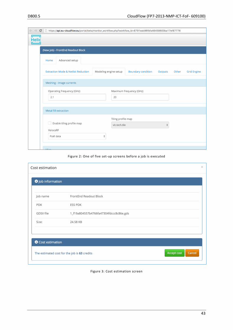
D800.5 CloudFlow (FP7-2013-NMP-ICT-FoF- 609100)
43
Figure 2: One of five set-up screens before a job is executed
Figure 3: Cost estimation screen

CloudFlow (FP7-2013-NMP-ICT-FoF- 609100) D800.5
44
Figure 4: Once cost has been estimated and user has accepted, the actual design to be modeled is displayed
Figure 5: Whilst the job is being executed, the user sees a progress bar
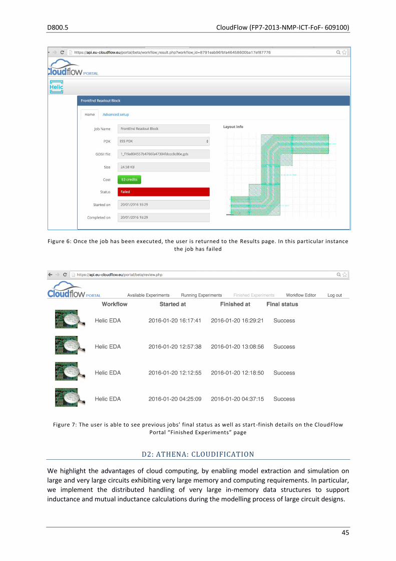
D800.5 CloudFlow (FP7-2013-NMP-ICT-FoF- 609100)
45
Figure 6: Once the job has been executed, the user is returned to the Results page. In this particular instance
the job has failed
Figure 7: The user is able to see previous jobs’ final status as well as start -finish details on the CloudFlow
Portal “Finished Experiments” page
D2: ATHENA: CLOUDIFICATION
We highlight the advantages of cloud computing, by enabling model extraction and simulation on
large and very large circuits exhibiting very large memory and computing requirements. In particular,
we implement the distributed handling of very large in-memory data structures to support
inductance and mutual inductance calculations during the modelling process of large circuit designs.

CloudFlow (FP7-2013-NMP-ICT-FoF- 609100) D800.5
46
D3: ESS: CHIP SIMULATION AND OPTIMISATION
EXPERIMENT ACTIVITY 3.1
Metal lines were separated from the rest of the ASIC’s layout and were turned into an autonomous,
initial layout. Extraction was initiated and successfully finished, producing a spectre/spice type of
netlist. These steps were executed several times in order to shrink the space between metal lines
and reach a much tighter layout, which in turn will free-up area to be used for inserting an internal
reference capacitor.
EXPERIMENT ACTIVITY 3.2
After having the models that corresponded to different placement of the metal lines, a generic
simulation Test-bench was created. By using the CVC’s (capacitance-to-voltage converter) output
noise was extracted for several metal lines’ placement, while the voltage waveforms produced were
checked for overvoltage. The experiment’s results so far tend to verify the initial hunch that due to
low-frequency operation of the chip, inductive effects are negligible. Therefore placing the
input/output metal lines as close as allowed by the Design Rules would create space for the insertion
of a reference capacitor on-chip.
D4: HELIC – CARSA: BUSINESS MODEL
Helic and CARSA discussed the business model from the ISV perspective. Some details are presented
in the corresponding section in this document.
MAIN ACTIVITIES IN THIS WORK PACKAGE, M25–M30
For Helic, the main activities of this work package were the integration to the Cloud Platform (2.3)
and GUI development and Backend system porting to Cloud (1.2). The GUI had to be redesigned in
order to be adapted to the sequential process (namely workflow) of performing tasks inside the
Cloud Platform. The integration also required careful planning and coordination with people from the
CCC, in order to maintain a seamless experience for the end users. Almost 5 000 lines of code were
written during this exercise.
Furthermore, Helic in collaboration with CCC implemented GridWorker and enabled such
functionality within the SaaS GUI.
A significant amount of effort went into testing and bug-fixing (1.3).
ATHENA focused on two major tasks in Helic's pipeline, in order to identify critical issues and
complexity bottlenecks:
Model extraction of the passive components of various RF circuits, as well as of power grid
networks. We considered polygon manipulation, efficient and scalable representation of
polygonal shapes, and fast approximation of capacitance by exploring the free space among
polygonal obstacles. A software prototype was developed. The conclusion was that this is not
the main complexity bottleneck of the process.
Netlist simulations are crucial since they determine the sensor front-end electronics design
layout and the way it may be optimised. The goal is to improve the time and space
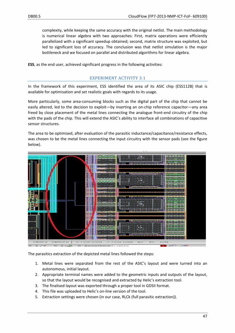
D800.5 CloudFlow (FP7-2013-NMP-ICT-FoF- 609100)
47
complexity, while keeping the same accuracy with the original netlist. The main methodology
is numerical linear algebra with two approaches: First, matrix operations were efficiently
parallelized with a significant speedup obtained; second, matrix structure was exploited, but
led to significant loss of accuracy. The conclusion was that netlist simulation is the major
bottleneck and we focused on parallel and distributed algorithms for linear algebra.
ESS, as the end user, achieved significant progress in the following activities:
EXPERIMENT ACTIVITY 3.1
In the framework of this experiment, ESS identified the area of its ASIC chip (ESS112B) that is
available for optimisation and set realistic goals with regards to its usage.
More particularly, some area-consuming blocks such as the digital part of the chip that cannot be
easily altered, led to the decision to exploit—by inserting an on-chip reference capacitor—any area
freed by close placement of the metal lines connecting the analogue front-end circuitry of the chip
with the pads of the chip. This will extend the ASIC’s ability to interface all combinations of capacitive
sensor structures.
The area to be optimised, after evaluation of the parasitic inductance/capacitance/resistance effects,
was chosen to be the metal lines connecting the input circuitry with the sensor pads (see the figure
below).
The parasitics extraction of the depicted metal lines followed the steps:
1. Metal lines were separated from the rest of the ASIC’s layout and were turned into an
autonomous, initial layout.
2. Appropriate terminal names were added to the geometric inputs and outputs of the layout,
so that the layout would be recognised and extracted by Helic’s extraction tool.
3. The finalised layout was exported through a proper tool in GDSII format.
4. This file was uploaded to Helic’s on-line version of the tool.
5. Extraction settings were chosen (in our case, RLCk (full parasitic extraction)).

CloudFlow (FP7-2013-NMP-ICT-FoF- 609100) D800.5
48
6. A cost was calculated and was accepted by the end user so that the extraction would
commence.
7. Extraction was initiated and successfully finished producing a spectre/spice type of netlist to
be downloaded to the end user’s site, representing the parasitics of the uploaded GDSII
structure.
The above described steps were implemented several times in order to shrink the space between
metal lines and reach a much tighter layout, which in turn will free up area to be used for inserting an
internal reference capacitor.
EXPERIMENT ACTIVITY 3.2
After having the models that corresponded to different placement of the metal lines, a generic
simulation Test-bench was created. This involved 3 main steps:
1. Correct isolation of the crucial input sub-circuits from the rest of the chip: this involves the a)
Sensor pads along with the metal lines up to the b) Capacitance-to-voltage converter (CVC)
with all the circuitry producing the necessary clock-phases, bias currents and the loading of
the CVC’s output which is the c) input switches of a Sigma-Delta Analogue-to-Digital
converter.
2. Incorporation of the metal lines extraction netlist into the overall netlist.
3. Deciding the simulation outputs’ metrics and therefore setting up the corresponding
simulations and the metrics.
In our case, CVC’s output noise was considered as the key metric for resolution. Regarding reliability,
the voltage waveforms on the input (pads) and on the output (internal circuitry) of the modelled
metal lines were chosen to be checked for any spikes that exceeded 3.6V (which is the upper limit
stated by the foundry of XFAB for reliable operation of the ASIC’s transistors).
So, by using the above described test bench, CVC’s output noise was extracted for several metal
lines’ placement, while the voltage waveforms produced were checked for overvoltage.
PROGRESS OF EXPERIMENT INTERNAL ACTIVITIES
# Activity Leader Start End
D1 Remote app. interface development and cloud interfaces
1.0 Collaboration with CloudFlow Competence Centre Helic M20 M27
1.2 GUI development and Backend system porting to Cloud Helic M21 M27
1.3 Testing and bug fixing Helic M23 M27
D2 Algorithmic Solutions
2.3 Integration to Cloud Platform Helic M26 M27
D3 Chip Simulation and Optimisation
3.1 Chip Parasitics extraction for inductance effects ESS M27 M29
3.2 Chip simulation and results analysis ESS M29 M31
D4 Experiment Reporting and Evaluation
4.1 Evaluation of Experiment and Business Models CCC M31 M31

D800.5 CloudFlow (FP7-2013-NMP-ICT-FoF- 609100)
49
# Activity Leader Start End
4.3 Experiment assessment and validation Helic M26 M31
4.4 Final reporting of results Helic M31 M31
Helic has completed activities 1.0, 1.2, 1.3, 2.3, as described in detail in the paragraph Significant
Results and Experiment Activities.
Deliverable 2: ATHENA and Helic examined several methods and packages for linear algebra
operations, namely Cholesky factorization (and inversion) for large symmetric positive-definite
matrices, in a distributed environment. We choose MPI for message passing, Intel’s MKLibrary as
software platform, BLAS for basic operations, and ScaLAPACK, the distributed version of matrix
library LAPACK. Based on these, we developed a distributed C++ implementation, and experimented
with matrices encountered in Helic's experiments of dimension up to more than 12 000.
The accuracy of our software is of about 15 significant digits. With 4 cores on Helic's cluster, the
acceleration is 3.26 or 3.43, respectively, if the cores lie on 2 machines or 1 machine; it is expected
that communication between machines somewhat reduces the speedup. An important feature is
that the acceleration increases as the matrix size grows. Both accuracy and speedup are quite
satisfactory from an algorithmic point of view and for the needs of Helic's experiments.
PROGRESS BEYOND STATE OF THE ART
ATHENA developed sophisticated parallel and distributed linear algebra methods and tested their
practical efficiency on a distributed environment. This illustrates the power of advanced distributed
algorithms and their relevance in addressing the main bottleneck in Helic's pipeline.
INTEGRATION IN THE CLOUDFLOW INFRASTRUCTURE
Helic developed two SOAP web services and registered those to the Workflow Manager from the
Workflow Editor. One web service follows the asynchronous service paradigm, while the other the
application service. These are then combined into a single workflow which takes up the role of
allowing the user to perform his extraction task, the process of which has been described above in
the significant results section. The workflow can be launched from the CloudFlow Portal as well and
is available as a button named “Helic EDA” in the experiments section. We also utilize the CloudFlow
Portal for its result history.
The Generic Storage Service has also been utilized in conjunction with the SWIFT back-end. The input
file of the end user is uploaded there and is afterwards readily available for the next service.
The Workflow Manager API, the GSS API and the authentication API are also directly used in our
services in order to maintain a seamless experience for the end user, without exposing him to
additional services.
Lastly, we take full advantage of the rich text outputs of workflows in order to present to the end
user an information webpage that maintains the previous look and feel of the services of our
workflow.
At the core of Helic EDA's processing sub-system, two very different components have been merged:
CloudFlow (FP7-2013-NMP-ICT-FoF- 609100) D800.5
50
VeloceRaptor/X, Helic's own proprietary state of the art electromagnetic modelling engine,
GridWorker Generic Simulation Service, high-performance grid computing system.
These two technologies have been combined into a single processing unit with the sole purpose of
producing an incredibly accurate and reliable EM description of a circuit using a blazing fast
calculation method. Harnessing the full power a cloud infrastructure, GridWorker will easily dispatch
multiple VeloceRaptor/X CPU-intensive calculation tasks to be executed simultaneously on multiple
computing nodes, using its innovative map && reduce technique.
Helic EDA processing unit will efficiently utilize GridWorker to map VeloceRaptor/X circuit modelling
tasks, automatically generated by means of parametric configuration files, to computational nodes
using three main extraction profiles:
High-Memory grid-disabled, to handle RAM-hungry special cases which would otherwise
yield only a small performance gain at the cost of utilizing a large amount of hardware
resources.
Large Dynamic, to handle in parallel, a large and variable in number, set of computational
tasks which would require an incredible amount of time, if executed sequentially on a single
processing node. GridWorker will on-demand configure the required number of processing
instances to handle the task, at the cost of a small overhead in order to provision the initial
processing environment for this dynamic group of nodes.
Static Medium, to handle medium-sized extraction tasks dispatched to a fixed-group of
always available low-latency computing nodes, thus removing the overhead required to
initialize resources in a Large Dynamic profile that ultimately would be comparable in terms
of processing time to the actual execution time to perform the model extraction.
Lastly, we take full advantage of the rich text outputs of workflows in order to present to the end
user an information webpage that maintains the previous look and feel of the services of our
workflow.
ATHENA and Helic carried optimisation code over to the Arctur cluster with similar performance in
terms of accuracy and speedup.
EXPERIMENT BUSINESS MODEL AND EXPERIMENT IMPACT
SOFTWARE PROVIDER
Helic’s plans for exploiting the opportunity to offer its tools (initially only one tool) over a SaaS
platform, remain unchanged, targeting the Academia and Research Institutes, as well as freelancers
and SMEs who offer IC design services.
Helic, in collaboration with CARSA, have clarified monetization aspects, although final pricing is yet to
be refined after contacts with a larger number of prospective end users. In particular, in terms of
monetization and business model, Helic envisions eventually offering an innovative “complexity
based” billing scheme, which, however, will require significant research and experimentation before
D800.5 CloudFlow (FP7-2013-NMP-ICT-FoF- 609100)
51
it evolves into a robust industrial tool. Until then, Helic may offer RaptorX3 SaaS version, on a per
CPU-hour model.
Given that Helic’s standard RaptorX version is currently sold at a 40 000 euro (starting price), Helic
may charge 200 euro per CPU-hour (for RaptorX’s multi-threaded version), which will still work out
cheaper for the end users than buying an annual license fee, as long as they have a usage pattern
that justifies up to 21 IC extraction jobs of an indicative 3 CPU-hours each.
END USER
The 3.2 experiment’s results so far tend to verify the initial hunch that due to low-frequency
operation of the chip, inductive effects are negligible. Therefore, it has been possible to place the
input/output metal lines as close as allowed by the Design Rules, and create space for the insertion
of an internal reference capacitor.
This will extend the ASIC’s ability to interface all combinations of capacitive sensor structures, such as
4-differential with common-node (4 sense capacitors or 2-sense and 2-reference capacitors) or 1
sense and 1 reference capacitors (with no common node) or 1 sense (external) accompanied by the
new internal reference capacitor.
So, the insertion of an internal reference capacitor will enable ESS to penetrate markets with one-
sense capacitor sensor, such as the capacitive humidity sensors.
EXPERIMENT DISSEMINATION
None of the partners has engaged in formal dissemination activities, such as presentations in events
and so on.
MILESTONES APPLICABLE TO THIS WORK PACKAGE, M25–M30
Milestone No.
Milestone name Activities involved Month
M1.1 Porting of Helic's application (RaptorX) onto Arctur 1.1, 1.2, 1.3, 1.0 27
M2.1 Model of ESS sensor chip 3.1, 3.2 31
M3.1 Integration of improved algorithms to Helic's (RaptorX) 2.1, 2.2, 2.3 27
DEVIATION FROM PLANS, M25–M30
Porting of Helic’s application to Arctur’s cluster has been delayed by 3 months, due to technical
issues. Nevertheless, this has not caused overall delays in the experiment, since ESS has been able to
experiment with Helic’s fully functional non-Arctur-integrated SaaS pilot platform (developed for the
CloudFlow project), which has been running on Helic’s internal cluster since M25.
Also, originally the overview of the job history was planned to be part of a service offered by the
system developed by Helic. However, integration to the CloudFlow infrastructure has made this
Helic-platform feature redundant and now end users are instead able to monitor the output of their
extraction tasks through the “Finished Experiments” tab in the CloudFlow Portal.
3 http://www.helic.com/products/raptorx

CloudFlow (FP7-2013-NMP-ICT-FoF- 609100) D800.5
52
DEVIATIONS FROM CRITICAL OBJECTIVES, M25–M30
There have been no deviations from critical objectives.
REFLECTION ON FUTURE PLANS FROM D800.4
All targets in our previous periodic report set have been achieved.
FUTURE PLANS
To be discussed.
USED RESOURCES, M25–M30
WP121
ESS HELIC ATHENA Sum
Used PMs M20-M24 2.00 7.20 1.99 11.19
Used PMs M25-M30 1.00 7.60 1.50 10.10
Available PMs M31 1.50 -3.10 0.01 -1.59
Planned M20-M31 4.50 11.70 3.50 19.70
D800.5 CloudFlow (FP7-2013-NMP-ICT-FoF- 609100)
53
2.11 WP122 — Plant Simulation and Optimization in the CLOUD
Start M20 End M31 Lead TTS
Participants FICEP, SUPSI
OBJECTIVES (AS STATED IN GRANT AGREEMENT)
3D simulation of complex manufacturing environments, specifically in the field of automated iron
beams production plants, is characterized by a high level of computational charge that requires high
performance hardware and software platforms as well as long calculation times. For this reason, up
to now, the FICEP Group has applied these tools only at technical office level, where the dedicated
hardware can be found, and only during the advanced design phase of a plant. Nevertheless,
simulation and optimization results would be useful also in the early commercial stage and not only
at FICEP’s premises, but also during technical meetings at customer sites. With the current
computational resources demand of the software, it would be impossible to make these
functionalities available on portable and multi-platform devices such as tablets, or light notebooks,
which represent the typical equipment of product managers. Thus, the idea behind this experiment is
to adapt the TTS simulation and production optimization engine to run in the cloud, centralizing both
the computational burden and the significant amount of plant data on high performance hardware,
exposing their functionalities both through thin multi-platform client applications and through
functional web services exploitable by third party software currently used to manage production
orders. In such a way, it would be possible, on the one hand, to provide the means to run production
simulations and optimization remotely, displaying only some selected performance indicators, which
are relevant to the current client user, and, on the other hand, to allow the integration with other
management software, which often accompanies the plant. Finally, in particular when dealing with
optimization of large production plans, it would of be of great impact to rely on HPC platforms
because it would reduce the software response times, improving the “what if” analysis both by the
technical office and at the customer premises.
FICEP (End User) will use the simulation and optimization services integrated within CloudFlow to
obtain fastest simulation times and a wide spread of optimization services, increasing the number of
“what if” scenarios available during the design phase and improving the productivity of the plants
with less burden on the technical office. The real plant will have a digital twin no longer limited in
terms of calculation potential, to offer unprecedented optimization capability. TTS will modify and
improve its 3D simulation engine, while the cloud-based infrastructure and HPC support will improve
both the management of large simulation models and the results achievable with the optimization
engine. Exposing the functionalities of the simulation engine through the cloud will increase the
interoperability with third party software and the number of supported hardware platforms. SUPSI
will support the requirement definition phase as well as the application of simulation and
optimization services gaining know-how and an expected breakthrough on the aspects of cloud-
based simulation, also thanks to the interaction with dynamic and proposing partners.

CloudFlow (FP7-2013-NMP-ICT-FoF- 609100) D800.5
54
ACTIVITY 122.1: (AS STATED IN GRANT AGREEMENT)
A1.1 — Reference framework formalization — M1–M3
This activity is meant to frame the envisaged developments and experiment in the context of
CloudFlow, harmonizing the domain-specific requirements (gathered in this activity) of FICEP and the
simulation software peculiarities with the larger picture of the project.
A1.2 — Collaboration with CloudFlow Competence Centre — M1–M3
This activity comprises collaboration between the participants of this experiment and the CloudFlow
Competence Centre existing partners and covers the following topics:
User requirements collection in collaboration with Task 120.2 of the CloudFlow work
packages.
Design of the technical integration of the new services with the existing CF infrastructure in
collaboration with the design tasks of the technical work packages in CloudFlow, namely
WP200, 300, 400 and 500.
Definition of new business models in collaboration with the design task of WP600 of the
CloudFlow work plan.
ACTIVITY 122.2: (AS STATED IN GRANT AGREEMENT)
A2.1 — Design and development of the 3D simulation service — M2–M6
This activity is meant to foster the adaptation of the current simulation engine and projection of the
services through the cloud infrastructure. The integration with the CloudFlow infrastructure is part of
this activity. (A2.1 depends on results from A1.)
A2.2 — Design and development of the production optimization service — M4–M8
This activity tackles the adaptation of the current optimization engine and projection of the services
through the cloud infrastructure. The integration with the CloudFlow infrastructure is part of this
activity. (A2.2 depends on results from A1.)
A2.3 — Development of the client software — M5–M10
This activity focuses on the development of the application capable to bring to the users the services
provided by A2.1 an A2.2. (A2.3 depends on results from A2.1 and A2.2.)
ACTIVITY 122.3: (AS STATED IN GRANT AGREEMENT)
A3.1 — Experiment Prototype development — M6–M12
This activity addresses the actual experiment accomplishment within FICEP test cases, also tackling
the actual experiment overall results assessment. This activity takes care of the evaluation of the
experiment and its related business model, providing feedback to adapt preliminary versions of the
engines. (A3 is to be carried out in collaboration with CF CC and depends on results from A2.1, A2.2
and A2.3.)
A3.2 — Experiment assessment and validation — M7–M12
This activity performs an assessment of the conformance of the implementation of the experiment
with the stated goals of the experiment and validates the experiments against the user, technical and
D800.5 CloudFlow (FP7-2013-NMP-ICT-FoF- 609100)
55
business requirements. The activity runs from month 7 to month 12, so early evaluation can be done
to refine and finally evaluate the improved version of a first implementation. The activity will be
conducted in collaboration with the CF CC.
A3.3 — Dissemination and future exploitation — M1–M12
This activity covers efforts for planning and running dissemination activities during the runtime of the
experiment to be reported in the progress reports and at the review after the experiment is
concluded.
INTERNAL EXPERIMENT DELIVERABLES DUE M25–M30
There were three internal experiment deliverables in the time range:
122.3 Experiment services — this deliverable is composed of the software and a report document.
The software is the executable of the plant simulation web service and of the plant optimization web
service, deployed as WAR (Web application ARchive) files. The files have been uploaded in the
project management website under the folder named “WP122 PLANTOPT > Internal 122.3
Experiment services”.
122.4 Experiment prototype — in the document there is an updated version of the web services
actual architecture and design, slightly changed during the development to accommodate the end
user feedback and to take advantage of the new features provided by CloudFlow infrastructure (e.g.
HPC service). A detailed description of the workflows, their inputs and outputs is provided, as well as
the description of the integration with the WebGL viewer developed by SINTEF.
122.5 Final results — Assessment report — it is a report of the validation of the execution of the
experiment: the user requirements are reviewed and validated against the actual implementation of
the software. The software validated is the Thin S&O Client, the simulation workflow and the
integration with SINTEF’s WebGL viewer.
ACTIVITIES ADDRESSED IN THIS WORK PACKAGE, M25–M30
A2.2 Design and development of the production optimization service (M23–M27)
A2.3 Development of the client software (M24–M29)
A3.3 Dissemination and future exploitation (M25–M31)
SIGNIFICANT RESULTS, M25–M30
The experiment has provided the following significant results to the project.
Integration with Arctur’s HPC infrastructure, with the support of software “modules” for
each simulation model (thus allowing access to each computing node).
Integration with HPC service, supporting the CloudFlow standard way of starting new jobs
on the HPC cluster. This will also ensure full and seamless integration with the accounting
and billing services that will be implemented by the CloudFlow infrastructure.
Full exploitation of CloudFlow’s GSS for storage of simulation models and sessions. This
allows easy integration with services developed by third parties (e.g. SINTEF’s WebGL
viewer). As for both the models the inputs and the results are available, other services can
be implemented to further process them (e.g., graphical visualization and comparison of
results).

CloudFlow (FP7-2013-NMP-ICT-FoF- 609100) D800.5
56
Development of services for pre-processing the input needed by the HPC service and post-
process the output.
Simulation and Optimization workflows based on the HPC service and pre- and post-process
services that can be reused inside other more complex workflows.
Thin S&O Client application designed to run on touch-enabled tablets, supporting
simulation, optimization, results comparison, upload of simulation modes.
MAIN ACTIVITIES IN THIS WORK PACKAGE, M25–M30
The main activities in the reporting period are reported below and detailed in the following section:
Design and development of the production optimization service.
Development of the client software.
Demonstration of the Thin S&O Client.
PROGRESS OF EXPERIMENT INTERNAL ACTIVITIES
Design and development of the production optimization service
During the last two months of the reporting period, this activity has focused on the design and
development of the integration of the new HPC service inside the architecture of the optimization
service. The HPC service was introduced after the architecture of the service was already prototyped,
and the implementation of the functionalities to start a job on the HPC infrastructure was already
developed. Nevertheless, the integration of the new service was done mainly to support the
integration of the accounting and billing features provided by CloudFlow infrastructure. Small
changes were also required to fully integrate with the GSS storage.
Development of the client software
The activities related to the development of the Thin S&O Client can be split into the following main
areas, most of them involving the interaction with one or more features of the CloudFlow
infrastructure:
1) Simulation and Optimization: These two features are implemented integrating with the
Workflow Manager SOAP interface, executing the respective workflow and watching its
status. Before starting, the list of available simulation models is loaded from the GSS (and
cached locally for faster access). After the workflow is completed, the results are
downloaded from the GSS and stored in a local session folder.
2) Results viewer and comparison: It is a graphical overview of the results file created by the
simulation or optimization. The relevant KPIs are shown both numerically and graphically,
allowing an easy comparison of the performances of different layouts. Supported KPIs are:
average Work-In-Process, productivity (in tonnes per hour and pieces per hour), average
piece weight and total worked volume. For each resource it is displayed the saturation level,
split as time spent in the following states: working, unloading, scarping, blocked.
3) Simulation model upload: It is possible to select a zip file containing the simulation model
created by the Simulation Editor and upload it to the default location on the GSS storage. The
zip file is also analysed in order to verify that it is a valid simulation model and it is optimized
for stream access.

D800.5 CloudFlow (FP7-2013-NMP-ICT-FoF- 609100)
57
All the interaction with the CloudFlow infrastructure is supported by the login function, where the
application user must specify a valid account from the CloudFlow Portal.
Demonstration
The demonstration activities have mainly targeted the Thin S&O Client, because the successful
execution of the experiment was based on it. An early demonstration of the application prompted
some changes to accommodate for user feedback. Nevertheless, the simulation and optimization
workflows and the WebGL viewer have been demonstrated as a generic way of accessing the
simulation and optimization services from the CloudFlow Portal.
PROGRESS BEYOND STATE OF THE ART
Currently, simulation and optimization tasks for large plant simulation models are performed on high performance desktop hardware provided with discrete graphic cards at FICEP premises and require running times ranging from 20 minutes to 2 hours, depending on the optimization parameters. These limitations determine the impossibility to use such tools during the commercial phase at the customer premises, where they could improve the quality of the requirements gathering process, of the user perception and increase the selling potentiality.
Using the Thin S&O Client it is possible to execute an optimization on the CloudFlow high
performance cloud infrastructure, decreasing the waiting time to obtain the results. The benefits are
twofold: on the one hand it is possible to start an optimization on low performance portable touch-
enabled tablets; on the other hand it is possible to explore more scenarios (different layouts,
parameters or optimization settings) because the computation power is not limited by the single
workstation the user is working on.
The availability of the simulation and optimization services on the CloudFlow Portal has already show
the benefit of the integration with third party services, with the integration of SINTEF’s WebGL
viewer. It is envisioned that a flourishing marketplace can be created around the availability to use
the simulation and optimization services inside other workflows.
INTEGRATION IN THE CLOUDFLOW INFRASTRUCTURE
The integration with the CloudFlow infrastructure is at many levels:
Simulation and optimization features are implemented as workflows, as the actual running of
the simulation model on the HPC is delegated to the HPC service. The corresponding
workflows are meant to provide explicit input and output parameters.
The session folder (where input data are read and output results are stored) is a folder on
GSS. It can be any folder as long as the user starting the workflow has access rights to it.
The simulation models are stored on GSS. They are used not only by the web application but
also by the client application.
A 3D graphical visualization of the simulation can be viewed in the browser using SINTEF’s
WebGL viewer.
The Thin S&O Client uses the Workflow Manager SOAP interface to start the execution of
workflows and to watch its status. It accesses the GSS using the Java library (to read the
simulation model, to write input parameters and to retrieve results). All interaction is done
using the CloudFlow Portal credentials specified in the application login dialog.
CloudFlow (FP7-2013-NMP-ICT-FoF- 609100) D800.5
58
EXPERIMENT BUSINESS MODEL AND EXPERIMENT IMPACT
The business idea behind this experiment is to adapt the TTS simulation and production optimization
engine to run in the cloud, centralizing both the computational burden and the significant amount of
plant data on high performance hardware, and to use it, on the one hand, to provide the means to
run production simulations and optimization remotely, displaying only some selected performance
indicators, which are relevant to the current client user, and, on the other hand, to allow the
integration with order management software, which often accompanies the plant. Additionally,
when dealing with optimization of large production plans, it will be of great impact to rely on HPC
platforms, because it will reduce the software response times, improving the “what if” analysis both
by the technical office and at the customer premises.
Potentially, each company, producing a plant (i.e. a system composed of machines whose interaction
and optimization is not easily predictable by standard means, such as Excel), either big or small, can
be a customer for this solution. We start from Steel Fabrication, as per the use case, while planning
an extension to woodworking plants developers (SCM, HOMAG, BIESSE) as a first commercial step.
The unitary cost of the cloud-based service can be estimated at: 40 000 euro license costs + 130 days
for setting up a simulation, for a total of around 120 000 euro. The cost for the customer is
comparable to the cost today: what changes is the quality of the optimization offered, which will
dramatically increase and will always be available. For TTS, the number of customers per year using
the new solution is expected to grow to 10, in 3 years time.
The overall business model, value proposition and related flows are presented in detail in the related
documentation produced together with CARSA.
EXPERIMENT DISSEMINATION
There are no activities on experiment dissemination in the reporting period.
MILESTONES APPLICABLE TO THIS WORK PACKAGE, M25–M30
There are no milestones in the reporting period.
DEVIATION FROM PLANS, M25–M30
There is not any significant deviation from planned activities for the reference period.
DEVIATIONS FROM CRITICAL OBJECTIVES, M25–M30
There is not any significant deviation from critical objectives foreseen by the description of work for
the reference period.
REFLECTION ON FUTURE PLANS FROM D800.4
The planned activities described in D800.4 have been completed as scheduled without any major
deviations. Minor adjustment has been made on the design and development of the simulation and
optimization services to use the HPC service that was not available at the planning time.
D800.5 CloudFlow (FP7-2013-NMP-ICT-FoF- 609100)
59
During the interim evaluation review the Thin S&O Client and the services were assessed together
with UNott.
FUTURE PLANS
Conforming to the planned scheduling, all main activities have been completed. Future plans are
about the long term evaluation of the envisioned business model, after the accounting and billing
service is made available by the CloudFlow infrastructure.
USED RESOURCES, M25–M30
TTS FICEP SUPSI Sum
Total PMs for experiment 7.0 4.0 4.0 15.0
Used PMs M20–M24 4.3 0.5 2.0 6.8
Used PMs M25–M30 3.5 3.0 1.5 8.5
Available PMs M25–M31 -0.8 0.5 0.5 0.2

CloudFlow (FP7-2013-NMP-ICT-FoF- 609100) D800.5
60
2.12 WP123 — SIMCASE
Start M20 End M31 Lead SimPlan
Participants INTROSYS, UNIKS
OBJECTIVES (AS STATED IN GRANT AGREEMENT)
The SIMCASE experiment will support collaboration throughout material handling or robot
simulations along the engineering service chain from engineering companies like the end user
INTROSYS to OEMs by bringing workflow support for simulation projects into the Cloud. Data
handling, workflows during the simulation study and simulation experiments will be shifted to the
Cloud and evaluated along a case study.
ACTIVITIES IN WP123: (AS STATED IN GRANT AGREEMENT)
A123.1 Collaboration with CloudFlow Competence Centre
A123.2 Requirements Analysis
A123.3 Implementation Cloud-Based Project Workflow with first version available in M6
A123.4 Evaluation and Assessment including adjustments to Implementation based on
Evaluation results
A123.5 Experiment Assessment and Validation
A123.6 Dissemination and future exploitation
The first three months of the project will be dedicated to a requirements analysis where SimPlan as
ISV will collect and describe the software features needed by INTROSYS. SimPlan knows INTROSYS
and its business processes from other joined projects and UNIKS already knows the existing client-
based workflow software very well. The second activity is focused on the implementation of the
experiment, i.e., the infrastructure is implemented and deployed using existing components and the
CloudFlow environment. During the final activity, evaluation and assessment, a real application use
case of INTROSYS is calculated using the deployed cloud-based workflow solution.
INTERNAL EXPERIMENT DELIVERABLES DUE M25–M30
One experiment internal deliverable was due and has been delivered in the reporting period: iD123.3
“Prototype” (CloudFlow Month 28 / Experiment Month 9). Additionally, the experiment reported its
status by providing input to the M24 Periodic and Progress report. This input to the overall project
deliverable D800.2 is equivalent to the internal experiment deliverable iD123.2 “Prototype and
Intermediate Report”. It was due on CloudFlow Month 25 / Experiment Month 6.
ACTIVITIES ADDRESSED IN THIS WORK PACKAGE, M25–M30
The following activities were addressed in this work package:
Participation in GridWorker training
Implementation of experiment and workflow according to DoW
o Final integration of SimAssist, GridWorker, and Plant Simulation
o Set up simulation model of welding cell in Plant Simulation

D800.5 CloudFlow (FP7-2013-NMP-ICT-FoF- 609100)
61
o Deployment of simulation model of welding cell to the cloud
Implementation of official Siemens PLM test license (runtime) on the Virtual Machine
Deployment of workflow onto the Virtual Machine
Preparation of and participation in the mid-term review meeting in London including
rehearsal, etc. (September)
Preparation of and participation in 2nd wave evaluation Telco (December 7th)
Ongoing collaboration with CloudFlow Competence Centre on business case, requirements
exploitation and dissemination, success stories, technical and administrative issues, and
periodic report
SIGNIFICANT RESULTS, M25–M30
This experiment has provided the following significant results to the project:
Successful implementation of the welding cell simulation experiment according to the DoW
integrating GridWorker, the existing Workflow tool, the SimPlan support software SimAssist,
and the third party commercial simulation tool Plant Simulation
MAIN ACTIVITIES IN THIS WORK PACKAGE, M25–M30
This experiment has carried out the following activities:
First internal review teleconference in early September 2015 (CloudFlow M27 / Experiment
M8)
Preparation of the CloudFlow mid-term review in London
Participation in the CloudFlow mid-term review in London
Regular participation in monthly administration teleconference for 2nd wave experiments
Regular participation in technical teleconferences
Participation in the GridWorker Code Camp in Dresden (CloudFlow M29 / Experiment M10)
Input to the 2nd intermediate report D800.2 (equal to iD123.2)
Bilateral meetings with CARSA on the SIMCASE business model and on exploitation
Teleconference with UNOTT on the evaluation of WP123
PROGRESS OF EXPERIMENT INTERNAL ACTIVITIES
The following progress was achieved on experiment internal activities:
Bilateral meetings (face-to-face and via WebEx/teleconference) between ISV and end user in
order to set up the simulation model of the welding facility
Bilateral implementation meetings between UNIKS and ISV
Completion of internal deliverable iD123.3
Talks with Siemens about supplying a PlantSimulation runtime license beyond CloudFlow
M31 (Experiment M12)
PROGRESS BEYOND STATE OF THE ART
The process of conducting a simulation project and conducting simulation experiments is still a very
individual and rather handcraft-like type of activity, with the software residing on rich clients at the
desk of each simulation engineer. The overall process and the outcome of simulation projects highly

CloudFlow (FP7-2013-NMP-ICT-FoF- 609100) D800.5
62
depend on the skills and the experience of the involved simulation experts and engineers. The
potential with respect to higher number of experiments, ease of data exchange, and collaboration
has been demonstrated to different degrees. While the increased number of experiments was shown
successfully, the benefit with respect to data handling and collaboration were demonstrated yet not
fully exploited. This is one of the focuses in the last month of the experiment (CloudFlow M31/
Experiment M12).
INTEGRATION IN THE CLOUDFLOW INFRASTRUCTURE
The experiment was successfully integrated into the CloudFlow infrastructure as indicated by the
following Figure. Details are given in iD123.3 and in the presentation for the mid-term reviews.
EXPERIMENT BUSINESS MODEL AND EXPERIMENT IMPACT
The business model was worked out with support of CARSA. The following table provides a summary
/ an overview on the various aspects of it.
INDICATOR 1 year
perspective
3 years
perspective
Number of proprietary
applications/workflows
in the cloud
Quantify the number of applications
or workflows with other solutions to
be exploited in a cloud based manner
1 (welding /
body-in-
white)
3 (welding,
values stream
management,
supply chains)
Customer
segment/niche
(see slide 4 for details)
Define the type of customers to be
addressed in terms of sector/industry,
customer profile, customer size (SME,
etc.)
OEMs, few
selected SMEs
Automotive
Sector
OEMs, SMEs,
x-Tier-
Suppliers
Automotive
Sector

D800.5 CloudFlow (FP7-2013-NMP-ICT-FoF- 609100)
63
Market size Quantify approximately the global
market size for that segment in terms
of number of buyers potentially
demanding the product/ service
300 (best
guess; no
facts & figures
available)
600 (best
guess; no
facts & figures
available)
Number of clients Quantify approximately the number
of final users that will pay for the
product/service
1 20
Market share Quantify approximately the
percentage (in terms of units or
revenue) of the market segment
addressed that will buy the product
/service
0.3% (pure
guess)
3.3% (pure
guess)
Number of new jobs
created
Quantify approximately the number
of jobs created as a consequence of
the cloud-based model
0.5 1.5
Number of sales to
existing clients
Quantify approximately the number
of unitary sales of the cloud-based
product /service to already existing
clients
1 5
Number of sales to
new clients
Quantify approximately the number
of unitary sales of the cloud-based
product /service to new clients
0 15
Average price
(see slide 4 for details)
Define approximately the average
price or prices of the cloud-services to
the previous clients
Revenue p.a.
and per client:
€ 1 800
Revenue p.a.
and per client:
€ 1 800
Total income Quantify the income derived from
total sales
Option 1): €
150 per
user/month
Option 2): € 6
per core/hour
Option to be
selected by
customer
€ 36 000 p.a.
from cloud-
service + € 30
000 – 60 000
p.a. from
client-based
solution and
value-added
services
Production and
commercial related
costs
Quantify approximately the total
costs raised from any type of activity
associated to the cloud-based
> € 30 000 p.a. > € 50 000 p.a.

CloudFlow (FP7-2013-NMP-ICT-FoF- 609100) D800.5
64
business model
Payback Estimate the period of time (normally
expressed in years) required to recoup
the funds expended in the investment
or to reach the break-even point
> 5 years —
first steps in
manufacturing
simulation in
the cloud;
break even
unclear
> 5 years —
first steps in
manufacturing
simulation in
the cloud;
break even
unclear
EXPERIMENT DISSEMINATION
There was one main dissemination activity in the reporting period
From September 23rd – September 25th SimPlan was exhibitor on the ASIM dedicated
conference Simulation in Production and Logistics in Dortmund, Germany. There, SIMCASE
was presented as an extension to the SimPlans software SimAssist.
MILESTONES APPLICABLE TO THIS WORK PACKAGE, M25–M30
Two experiment internal milestones were achieved (see following table as excerpt from the DoW):
Milestone No. Milestone name Expected
month
Comment Milestone
Achieved
M2 Intermediate
results
M25 /
M6
Results of the requirements analysis and
status of the implementation/deployment
of the solution will be presented
Y
M3 Implementation
completed
M29 /
M10
A running prototype of the cloud-
integrated workflow software and the
corresponding document are available
Y
DEVIATION FROM PLANS, M25–M30
No major deviation
DEVIATIONS FROM CRITICAL OBJECTIVES, M25–M30
No major deviation
REFLECTION ON FUTURE PLANS FROM D800.4
Future plans that have been stated in D800.4 have been implemented.
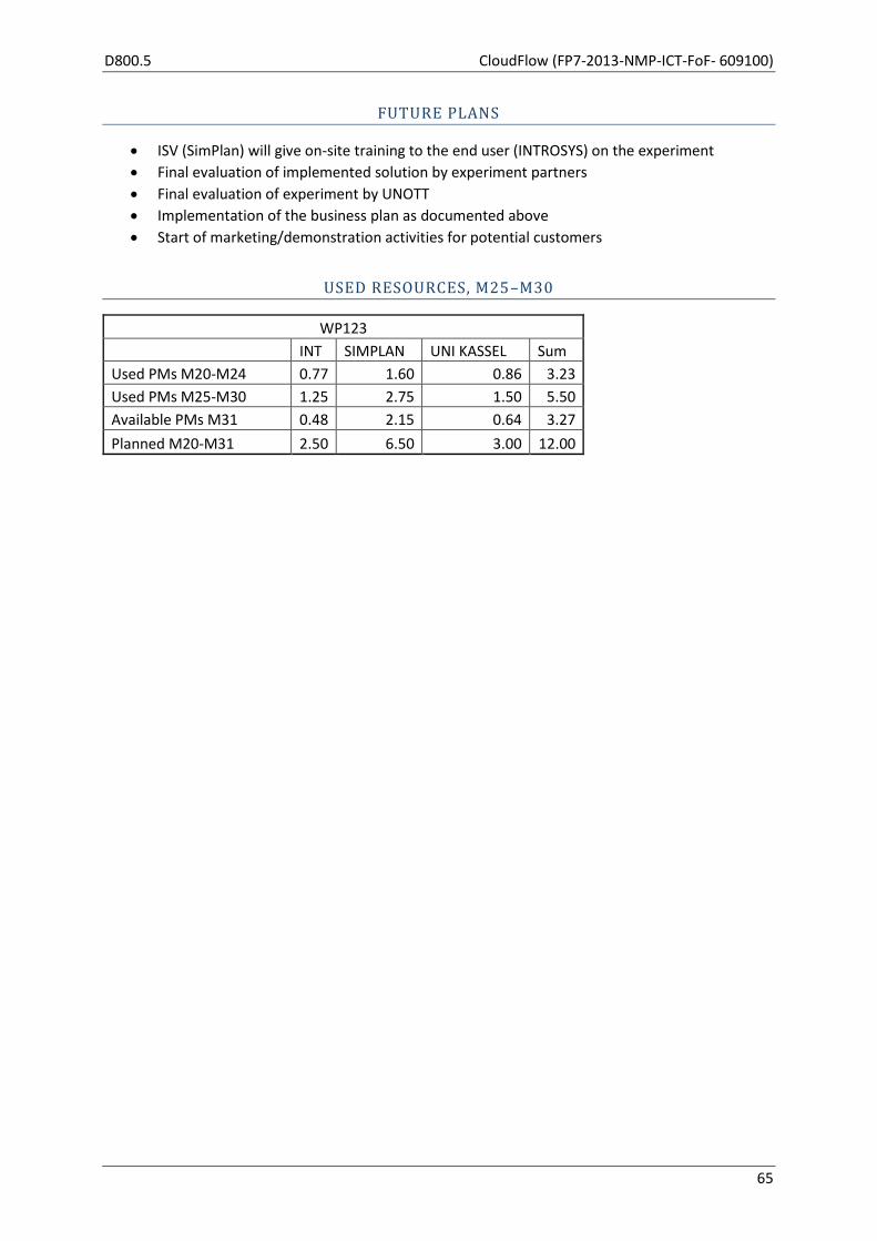
D800.5 CloudFlow (FP7-2013-NMP-ICT-FoF- 609100)
65
FUTURE PLANS
ISV (SimPlan) will give on-site training to the end user (INTROSYS) on the experiment
Final evaluation of implemented solution by experiment partners
Final evaluation of experiment by UNOTT
Implementation of the business plan as documented above
Start of marketing/demonstration activities for potential customers
USED RESOURCES, M25–M30
WP123
INT SIMPLAN UNI KASSEL Sum
Used PMs M20-M24 0.77 1.60 0.86 3.23
Used PMs M25-M30 1.25 2.75 1.50 5.50
Available PMs M31 0.48 2.15 0.64 3.27
Planned M20-M31 2.50 6.50 3.00 12.00

CloudFlow (FP7-2013-NMP-ICT-FoF- 609100) D800.5
66
2.13 WP124 — Cloud-Based HPC Supported Cooling Air-Flow
Optimization for industrial machines shown exemplary for compressors
Start M20 End M31 Lead Capvidia
Participants BOGE
OBJECTIVES (AS STATED IN GRANT AGREEMENT)
In compressors exemplary for industrial, mechatronic machines, cloud computing will help to
improve the flow of cooling air through the device, optimizing its efficiency by lower fan power and
reduction of acoustic emission. Using CFD multi-domain software tools, for small and medium-sized
enterprises preferably as a cloud-based service, will help related industries to improve product
design and quality with respect to the mentioned parameters and evaluate many necessary design
variants without building expensive and time-consuming prototype test samples except one for
verifying the final simulation/calculation result in the end of the outlined experiment.
ACTIVITY 124.0: COLLABORATION WITH CLOUDFLOW COMPETENCE CENTRE (AS STATED IN GRANT AGREEMENT)
This activity comprises the collaboration between the participants of this experiment and the
CloudFlow Competence Centre partners covering the following topics:
User requirements collection in collaboration with Task 120.2 of the CloudFlow work
packages.
Design of the technical integration of the new services with the existing CloudFlow
infrastructure in collaboration with the design tasks of the technical work packages in
CloudFlow, namely WP200, 300, 400 and 500.
Definition of new business models in collaboration with the design task of WP600 of the
CloudFlow work plan.
ACTIVITY 124.1: HPC CONFIGURATION OF VM (AS STATED IN GRANT AGREEMENT)
After starting the installation, it is necessary to create appropriate virtual machines through
GridWorker (from the CloudFlow platform) that will contain the different FlowVision modules. It is
also necessary to provide IP addresses and open the ports to allow the connection between different
virtual machines and the physical HPC. This activity is addressed by the cooperation between the HPC
provider ARCTUR and CAPVIDIA.
The tight integration of FlowVision on the CloudFlow server is now mostly completed. We plan to be
operational by the end of January 2016.
ACTIVITY 124.2: HPC INSTALLATION OF FLOWVISION WITH CONNECTION CHECK (AS STATED IN GRANT AGREEMENT)
In preparation for Cloud usage, the FlowVision CFD software needs to be installed on the Cloud
computer, accessible to the user. To achieve this goal, the configuration chosen includes installing
D800.5 CloudFlow (FP7-2013-NMP-ICT-FoF- 609100)
67
the licensing on a Linux virtual machine, the pre-post processor on a Windows virtual machine with
direct access for the client, and the solver module installed physically on the HPC.
ACTIVITY 124.3: DEFINITION AND PREPARATION OF EXPERIMENT DATA (AS STATED IN GRANT AGREEMENT)
BOGE as the manufacturing partner will perform the necessary steps for the optimization
experiment, by collecting the overall requirements concerning heat-flow to be cooled, the overall
dimensions and characteristics of the plastic foam (for noise absorption) and the fans which are
available, followed by designing different variants of the noise reducing enclosure in the present
BOGE SolidEdge CAD system. The data exchange will be based on the Parasolid XT file format.
ACTIVITY 124.4: PREPARATION OF EXPERIMENT CAD DATA FOR SIMULATION (AS STATED IN GRANT AGREEMENT)
The CAD models will be the input data, prepared for the CFD analysis executed by CAPVIDIA in order
to establish a first stable simulation setup.
ACTIVITY 124.5: TRAINING SESSION INCLUDING PREPARATION (AS STATED IN GRANT AGREEMENT)
In order to enable BOGE to perform the simulation, a FlowVision CFD training session will be
prepared and conducted between CAPVIDIA and BOGE.
ACTIVITY 124.6: VARIANT SIMULATIONS (AS STATED IN GRANT AGREEMENT)
In this activity, BOGE will perform the following simulation workflow: The user operates from a local
computer and sets up a simulation project definition. The process starts with importing a 3D CAD
model into FlowVision and checking the consistency of the model by diagnosing potential errors. The
next step is to define substance and material properties. After that the boundary conditions are
defined and the physical models and initial conditions are selected. A definition of the initial grid is
needed as adaptation for the solver to be used to generate the final mesh. As a final step, it is
necessary to choose the solver settings and start the simulation. The mesh generation process is an
integral part of the FlowVision solver and runs on HPC/Cloud. Once a connection with the solver is
established the simulation process starts. During the simulation process, the user gets information
about the status of the calculation (updated with each iteration) and can follow graphically the
results of the ongoing simulation—fully interactively during the whole process.
ACTIVITY 124.7: INTERMEDIATE REPORT (AS STATED IN GRANT AGREEMENT)
This activity report provides information about the project progress achieved in the CloudFlow
experiment at the point of the project completion.
ACTIVITY 124.8: EVALUATION OF SIMULATION RESULTS (AS STATED IN GRANT AGREEMENT)
The simulation results will then be compared to the experimental results provided and performed by
BOGE. In order to improve the accuracy of the computation/simulation for the best possible match

CloudFlow (FP7-2013-NMP-ICT-FoF- 609100) D800.5
68
with existing experimental results, the density for the mesh adaptation for the next simulation run
will be increased, thus getting more accurate results. This cycle will be repeated several times in
order to find the optimal solution. It is expected that several design variants and corresponding
computing will be carried out. Finally BOGE will choose the best result (in terms of noise and fan
power), so that the most promising design will then be built and verified physically.
A promising configuration of the design was defined, after which the work focused on simulations
verifying the new design concepts and physical measurements to verify correctness.
ACTIVITY 124.9: PREPARATION OF DOCUMENTATION/PUBLISHING EXPERIMENT (AS STATED IN GRANT AGREEMENT)
The findings of Activity 8 will be documented in the form of text and graphs/images in order to be
published via the Internet and scientific magazines in cooperation between BOGE and CAPVIDIA.
The documentation work is being now progressed, as most of the materials are available or entering
the stage of the final completion.
ACTIVITY 124.10: EXPERIMENT ASSESSMENT AND VALIDATION IN COOPERATION WITH CF CC
(AS STATED IN GRANT AGREEMENT)
This activity performs an assessment of the conformance of the implementation of the experiment
with the stated goals of the experiment and validates the experiments against the user, technical and
business requirements. The activity runs from month 7 to month 12, so early evaluation can be done
to refine and finally evaluate the improved version of a first implementation. The activity will be
conducted in collaboration with the CF CC.
ACTIVITY 124.11: DISSEMINATION AND FUTURE EXPLOITATION (AS STATED IN GRANT AGREEMENT)
This activity covers efforts for planning and running dissemination activities during the runtime of the
experiment to be reported in the progress reports and at the review after the experiment concluded.
INTERNAL EXPERIMENT DELIVERABLES DUE M25–M30 IN WP124
Two experiment internal deliverables were due in Experiment month 4 (CloudFlow month 23) and
were submitted in month 5 (CloudFlow month 24):
HPC/CFD setup
Experiment parameter setup
Three internal deliverables were due in Experiment month 6–8 (CloudFlow month 25–27) and were
submitted in month 11 (CloudFlow month 30):
Simulation of variants
Business model
Final simulation variant

D800.5 CloudFlow (FP7-2013-NMP-ICT-FoF- 609100)
69
INDUSTRIAL RELEVANCE OF THE WP124 EXPERIMENT
As one of the leading companies in Germany for the development and production of industrial
compressors, BOGE Kompressoren GmbH & Co KG, with a market share of approximately 2% in a 6
billion euro market segment, drives the experiment, which addresses the design of noise reducing
enclosures for compressors with a strong flow of cooling air through them.
For the project, an oil-injected screw compressor, the 110 kW-type from the BOGE S-series (all S-
types are built in the same pattern), will be analyzed in its basic configuration without inverter or
integrated dryer (under the name “S150-3” for 8bar(g), noise 79 dB(A) at a 1 meter distance, 3.94
kW-shaft fan power).
A large flow of cooling air is required because of the heat produced inside the compressor enclosure.
Therefore openings to the enclosure need to be implemented. The contrast is to minimize the noise
emission on one hand, which requires small openings, but openings too small need a strong fan,
which increases the noise on the other hand. Such contradicting requirements are typical design
challenges, which are aimed to be solved more efficiently through the experiment. Today, the
enclosures are designed first, while a fan is chosen following a rule of thumb. A test sample for an
enclosure needs to be created for measuring temperature and noise. This task is repeated in a 2- or
3-step iterative process in order to improve the enclosure-fan combination. As described, today this
iterative process does not include any computerized simulation model (except 3D CAD data) or CFD
approach. The aim of using CFD is to minimize the number of prototypes to be created per new
product release from approximately three today to only one, to reduce research and development
time by an estimated 30%, to improve the design result and optimize the choice of a fan. The
proposed approach will optimize the design for the compressor enclosure and should no longer be
based on the human factor (or on a “best guess”), but on proven approximations, calculated by the
CFD solution.
As of today, the implemented process requires approximately 3–5 months of development time for
the design of the S150 compressor–enclosure combination. This does not mean months of steady
testing, but doing a test with measuring a set-up of the enclosure under several circumstances,
measuring sound, cooling and fan power, guessing the reasons, designing a modification (next
iterative step), procuring new sheet metal parts and/or a new fan and/or new sound absorbing
plastic foam for that modification, waiting until these parts are ready, doing the next test several
days (often weeks) later. That process is repeated until a reasonable result is identified and chosen.
As the testing time is limited, the process often ends when a noise limit is reached, instead of when
an optimal enclosure is found. The main expected benefit is a better solution for the noise reduction,
serial production costs and fan power. As of today, the cost of the design process falls between 50
000 and 120 000 euro, due to the fact that the design process is frequently interrupted. It is a
combination of setting up a plan for the next try for the next sound reducing enclosure variant, the
procurement of materials, the preparation of the compressor with the material, the availability of
the test bed and processing the actual sound test.
The software to be used is provided by CAPVIDIA and is called FlowVision CFD.
The main expected benefit is a minimization of the noise emission of the compressor, which in the
past was based on a “best guess” following a rule of thumb. The goal is to find the best compromise
for the enclosure cooling openings, the usage of noise absorbing materials and fan size/fan power
consumption. Using CFD with HPC will provide a more analytical approach and the ability of testing
numerous design variants as computer models. This will lead to a fast and easy solution for the

CloudFlow (FP7-2013-NMP-ICT-FoF- 609100) D800.5
70
optimal design of the sound reducing enclosures. As a result there will be less noisy, more affordable,
less fan-power-consuming and therefore more attractive compressors systems.
BOGE has a market share of approximately 2% in a 6 billion euro compressor market segment. As
noise becomes an important point for buying compressors, a successful CloudFlow experiment result
should help to increase the BOGE turnover by some 4% in 3 years.
For BOGE, the experiment will demonstrate that CFD for complex problems, which require large
investments into HPC resources, can be used efficiently, even without operating one’s own CFD
department. Getting access to HPC and the expertise to use complex software like CFD through the
cloud will simplify the access to such software.
From the ISV perspective — CAPVIDIA — CFD simulation has traditionally been used exclusively in
large corporations and research organizations. The main reason for that is the high cost. Additionally,
highly educated resources are required to use the technology due to the high level of complexity.
The annual cost for CFD simulation can easily exceed 350 000 euro, to cover software licenses,
hardware and the cost of an operator. This level of cost/investment makes it impossible for SME’s to
benefit from this technology in the traditional way. Cloud computing could be an alternative usage
model.
The software FlowVision is used in multiple markets and industries, such as Automotive, Aerospace,
Compressors (machinery), Medical, and Chemical. Hence providing easy access to CFD simulations
with FlowVision can be useful for many sectors in related industries, where both noise and heat have
to be tackled (like in the experiment with BOGE) and owning a specialized CFD departments (as in
large-scale enterprises) is not affordable.
The estimated market share of CAPVIDIA’s FlowVision today is estimated at 1 – 2% and should be
increased during the next 1–3 years following the experiment by an estimated 0.5 – 1%.
An important factor for CAPVIDIA will be to provide an alternative usage model for the CFD solution
FlowVision also in a cloud environment, which will generate additional customers/revenue, not
generated by the CFD solution for CAPVIDIA so far. For the three years following the experiment,
FlowVision’s revenue is expected to increase by approximately 25 – 35%. Beside the additional
CloudFlow Portal usage revenue, the aspect of providing simulation project related services, such as
user training and CFD consultancy are important business impacts for CAPVIDIA.
In CAPVIDIA’s opinion Cloud computing can address the following customer groups:
SME’s looking for alternatives to CFD consulting services,
Occasional CFD users (who cannot afford an internal CFD department) and
Customers faced with a temporary shortage of computational resources.
In addition cloud computing provides access to “unlimited” computational power at relatively low cost, which is very much in line with the market tendency to solve more and more challenging CFD problems requiring huge computational resources. A major market growth is expected from SME’s. More complex products call for more simulation in the early product design phase, while pressure to suppress the costs is continuously growing.
D800.5 CloudFlow (FP7-2013-NMP-ICT-FoF- 609100)
71
ACTIVITIES ADDRESSED IN WP124, M25–M30
Activity: 0 Collaboration with CloudFlow Competence Centre
Activity: 1 HPC configuration of VM
Activity: 2 HPC installation of FlowVision with connection check
Activity: 3 Definition and preparation of experiment data
Activity: 4 Preparation of experiment CAD data for simulation
Activity: 5 Training session including preparation
SIGNIFICANT RESULTS FOR WP124, M25–M30
This experiment has provided the following significant results. It was possible to demonstrate the
viability of the cloud. Tutorials provided by a CFD expert were used and considered very helpful. The
lessons were provided via the Internet by people located in different countries, resulting in a much
faster start with CFD than by reading manuals and doing exercises alone. The existing compressor
enclosure, which was built and physically measured last year, has been converted into a CFD model.
Difficulties in getting a first promising CFD result have been identified and are subject to be solved
shortly.
With respect to the single activities the most important results are:
• Activity 0 – Activity 2:
The FlowVision Solver has been installed on the ARCTUR cluster. Special configuration of the
Solver on the cluster allowed starting the simulation directly from the GUI of FlowVision. The
user just chooses the number of processors in FlowVision, defines the pre-post processor and
waits for the Solver to be started on the cluster. Note: the modular structure of FlowVision
allows preparing the project on a virtual machine without the Cluster and carries out the
simulation without a Windows virtual machine.
Collaboration with CF CC was intensive at the end of the reporting period, as the work stated
aimed at a tight FlowVision integration into the CF portal.
• Activity 3: Definition and preparation of experiment data
BOGE 3D CAD models provided from the SolidEdge CAD system have been simplified.
Although FlowVision allows simulating very complex assemblies, some details do not have
any influence on the flow. Excluding such details allows decreasing the computational grid
and so allows faster simulation.
• Activity 4: Preparation of the experiment CAD data for simulation
The computational mesh has been set up automatically with FlowVision after importing the
prepared CAD data per activity 3. As a result of the simplifications the number of cells could
be reduced.
• Activity 5: Training sessions including preparation
Training sessions have been carried out for BOGE. Training was based on real model data,
using the FlowVision pre-post processor on the Windows virtual machine and the FlowVision
Solver on the ARCTUR cluster. The connection with RDP to Windows Virtual Machines is
typically used by many companies. This way of setup provides a simple and clear process for

CloudFlow (FP7-2013-NMP-ICT-FoF- 609100) D800.5
72
the end user. The interface of FlowVision is also clear and simple and allows starting
simulations rather quickly.
• Activity 6: Variant Simulation
Simulations of various compressor configurations have been the main activity in the
reporting period. The simulations were performed in search for optimal computational
parameters and optimal geometry configuration and mesh granularity for effective
calculations. The simulations can be concluded as successful. The results are correct, in the
sense that they provide optimal computational settings, geometry input (sub-domain
analysis), and mesh density. The latter is a compromise on computational time and acoustic
resolution needed to make correct engineering assessments possible to verify with
experimental data.
• Activity 7: Intermediate report
The intermediate report was delivered.
• Activity 8: Evaluation of simulation results
The activity has been completed. From the set of simulations, one promising design (in terms
of noise and fan power) has been chosen for further validation with experiments. The
physical modifications have also been completed, allowing physical measurements. A good
correspondence with the simulation is achieved.
• Activity 9: Preparation of documentation/publishing experiment
Most of the documentation has been generated and is now available.
• Activity 10: Experiment assessment and validation in cooperation with CF CC
There is nothing to report at this time.
• Activity 10: Dissemination and future exploitation
Some internal and external dissemination activities can be reported:
29.09.2015 — Participation at ISC Frankfurt
22–25.09.2015 — CloudFlow review, London
MAIN ACTIVITIES FOR THE EXPERIMENT WP124, M25–M30
The main activities in the reported project period were:
Investigating various design changes in the compressor configuration aimed at lowering the
noise level — BOGE (Activity 6)
Work related with finding optimal computational parameters (to minimise the simulation
time such as size of the simulation domain model and size of the computational mesh) and
preparation of FlowVision projects for running on the CloudFlow platform — CAPVIDIA
D800.5 CloudFlow (FP7-2013-NMP-ICT-FoF- 609100)
73
PROGRESS OF EXPERIMENT INTERNAL ACTIVITIES
So far two internal deliverables have been submitted:
1. Internal deliverable 124.1 — HPC/CFD Setup:
The subject of this internal deliverable consists of:
Description of the Software and Hardware structure
Configuration of the Cluster
Configuration of the FlowVision modules
Interaction with the Cluster
Workflow
2. Internal deliverable 124.2 — Experiment Parameter Setup:
The subject of this internal deliverable consists of:
Air Compressor Assembly: Problem Statement
o Overview
o Preparing the 3D CAD model
Preparing CFD Project in FlowVision
o Simplifications
o Importing the 3D models
o Boundary conditions
o Simulating of grids and radiators
o Physical model and solver properties
o Computational mesh
o Preliminary results
The fan grid, made of wires, was simplified in the CAD to be viable for the CFD. The geometry of the
cooler was simplified as an anisotropic resistant body. Numerical instability could be fixed by setting
the transversal resistance of the anisotropic resistant body to a lower value. The fan torque value
was found to be unstable in the first numerical experiment. A finer mesh at the fan blades seems to
give better results.
Several meetings have taken place, especially between CAPVIDIA and BOGE:
March–June:
05.03.2015: Telco CAPVIDIA/BOGE — Project Planning, CloudFlow Kickoff report
02.04.2015: Technical Telco CAPVIDIA/BOGE — CAD Geometry discussion
16.04.2015: Technical Telco CAPVIDIA/BOGE — Experiment Parameter Setup
27.04.2015: Web meeting CAPVIDIA/BOGE — Status/Next Steps
29.05.2015: Web meeting CAPVIDIA/BOGE — Status/Next Steps
08.06.2015: Internal call CAPVIDIA/BOGE — Status/Training Planning
25.06.2015: Web meeting CAPVIDIA/BOGE — FlowVision Online Training

CloudFlow (FP7-2013-NMP-ICT-FoF- 609100) D800.5
74
July:
01.07.2015: FlowVision training for BOGE
15.07.2015: FlowVision training for BOGE
29.07.2015: Technical Conference with BOGE
August
06.08.2015: Technical Conference with BOGE
07.08.2015: FlowVision training for BOGE
11.08.2015: Technical Conference with BOGE
20.08.2015: Technical Conference with BOGE
28.08.2015: Pre-evaluation technical meeting
September:
11.09.2015: BOGE telco, CF London preparation
03.09.2015: FlowVision training for BOGE
08.09.2015: Technical Conference with BOGE
14.09.2015: BOGE telco, CF London preparation
16.09.2015: BOGE telco, CF London preparation
7–9.09.2015: Model preparation for simulation
October:
15.10.2015: Technical Conference with BOGE
23.10.2015: Technical Conference with BOGE
November:
17.11.2015: Technical Conference with BOGE
24.11.2015: Technical Conference with BOGE
27.11.2015: Technical Conference with BOGE
December:
08.12.2015: Technical Conference with CF integration team
Additionally, the partners have attended the following CloudFlow meetings/events:
24–26.02.2015: CloudFlow Kickoff Madrid Onsite — CAPVIDIA, ARCTUR

D800.5 CloudFlow (FP7-2013-NMP-ICT-FoF- 609100)
75
27.04.2015: CloudFlow Management Meeting Online — CAPVIDIA with status report
26.05.2015: CloudFlow Management Meeting Online — CAPVIDIA with status report
30.06.2015: CloudFlow Management Meeting Online — CAPVIDIA with status report
PROGRESS BEYOND STATE OF THE ART
Usual CFD solutions of cooling air flow do not include fine wire meshes and exact flow at the fan
blades. BOGE could now incorporate these items by using HPC. In a first attempt with every detail
calculated, too many HPC resources were consumed (approximately a week of computing time for
every variation of the model was needed). At the end of the reporting period some simplifications
were tested, to find a solution for making the CFD mesh smaller and thus the computation faster for
quick and exact CFD results. A final compromise, between the level of resolution and computing time
is expected to be found end of M26.
The compromise between the simulation accuracy and simulation time has been successfully
established as planned, which makes the further investigations more efficient and faster.
The splitted-type silencers (named “Kulissen” in our CFD-model) are an important part of sound-
reducing enclosure. We faced difficulties in evaluating the sound reduction at lower sound frequency
(< 500 Hz, Piening formula works only for higher frequency). It was found, that CFD can calculate the
sound pressure waves passing through them (while the airflow is modelled at the same time). This
was only possible for a restricted model (only 3 silencers instead of 5 in the enclosure and only as a
quasi 2D model), but now it was possible to compare different kinds of silencers and to choose the
best one.
PROGRESS OF EXPERIMENT REQURIEMENTS
Together with UNott a meeting has taken place at the CloudFlow Kickoff in Madrid, 24–26.02.2015.
Based on the preparation in Madrid, a table has been prepared concerning the following criteria:
User Requirements
Success Criteria
Measurement Methods
Technical Feasibility
Priority
All experiment partners (BOGE, CAPVIDIA, ARCTUR) have delivered input with respect to their role in
the experiment.
PROGRESS OF EXPERIMENT BUSINESS MODEL AND EXPERIMENT IMPACT
Together with CARSA a meeting has taken place at the CloudFlow Kickoff in Madrid, 24–26.02.2015.
Based on the preparation in Madrid, a document has been prepared concerning the existing
FlowVision business model with information related to:
Value proposition, Distribution, Marketing, Customer relationship, Customers, Revenue
stream, Key resources, Key activities, R&D, Procurement, Production, Administration and
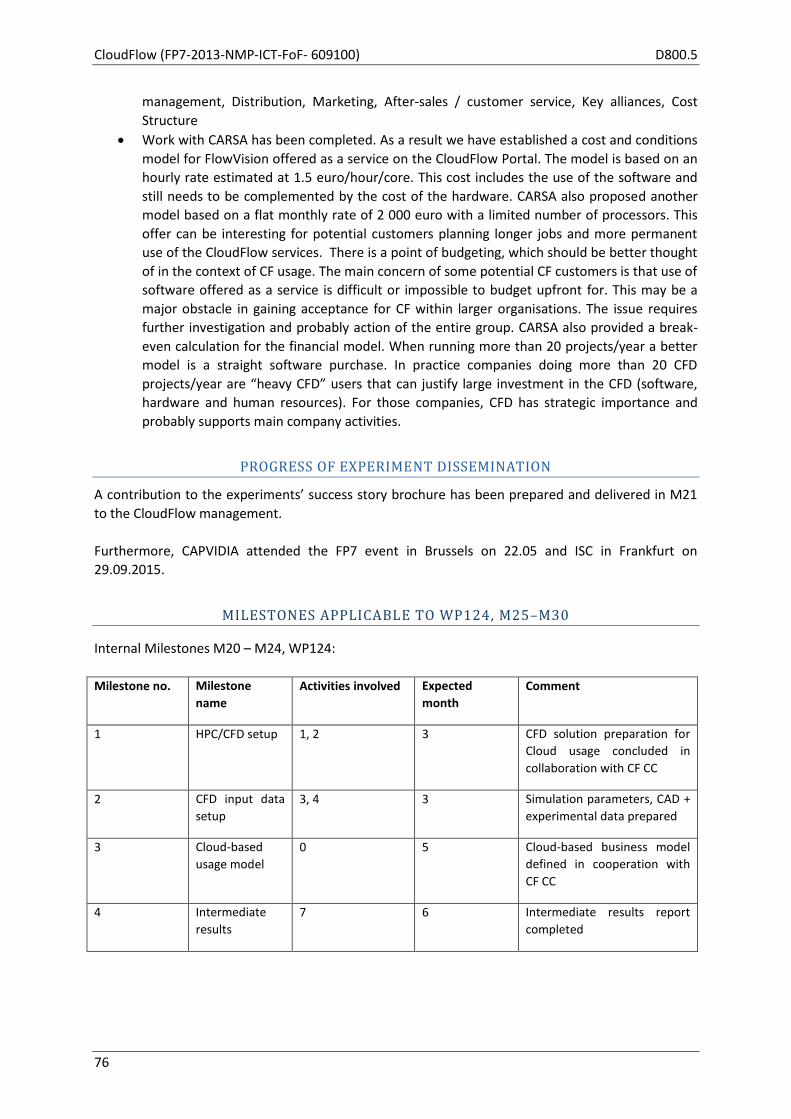
CloudFlow (FP7-2013-NMP-ICT-FoF- 609100) D800.5
76
management, Distribution, Marketing, After-sales / customer service, Key alliances, Cost
Structure
Work with CARSA has been completed. As a result we have established a cost and conditions
model for FlowVision offered as a service on the CloudFlow Portal. The model is based on an
hourly rate estimated at 1.5 euro/hour/core. This cost includes the use of the software and
still needs to be complemented by the cost of the hardware. CARSA also proposed another
model based on a flat monthly rate of 2 000 euro with a limited number of processors. This
offer can be interesting for potential customers planning longer jobs and more permanent
use of the CloudFlow services. There is a point of budgeting, which should be better thought
of in the context of CF usage. The main concern of some potential CF customers is that use of
software offered as a service is difficult or impossible to budget upfront for. This may be a
major obstacle in gaining acceptance for CF within larger organisations. The issue requires
further investigation and probably action of the entire group. CARSA also provided a break-
even calculation for the financial model. When running more than 20 projects/year a better
model is a straight software purchase. In practice companies doing more than 20 CFD
projects/year are “heavy CFD” users that can justify large investment in the CFD (software,
hardware and human resources). For those companies, CFD has strategic importance and
probably supports main company activities.
PROGRESS OF EXPERIMENT DISSEMINATION
A contribution to the experiments’ success story brochure has been prepared and delivered in M21
to the CloudFlow management.
Furthermore, CAPVIDIA attended the FP7 event in Brussels on 22.05 and ISC in Frankfurt on
29.09.2015.
MILESTONES APPLICABLE TO WP124, M25–M30
Internal Milestones M20 – M24, WP124:
Milestone no. Milestone
name
Activities involved Expected
month
Comment
1 HPC/CFD setup 1, 2 3 CFD solution preparation for
Cloud usage concluded in
collaboration with CF CC
2 CFD input data
setup
3, 4 3 Simulation parameters, CAD +
experimental data prepared
3 Cloud-based
usage model
0 5 Cloud-based business model
defined in cooperation with
CF CC
4 Intermediate
results
7 6 Intermediate results report
completed
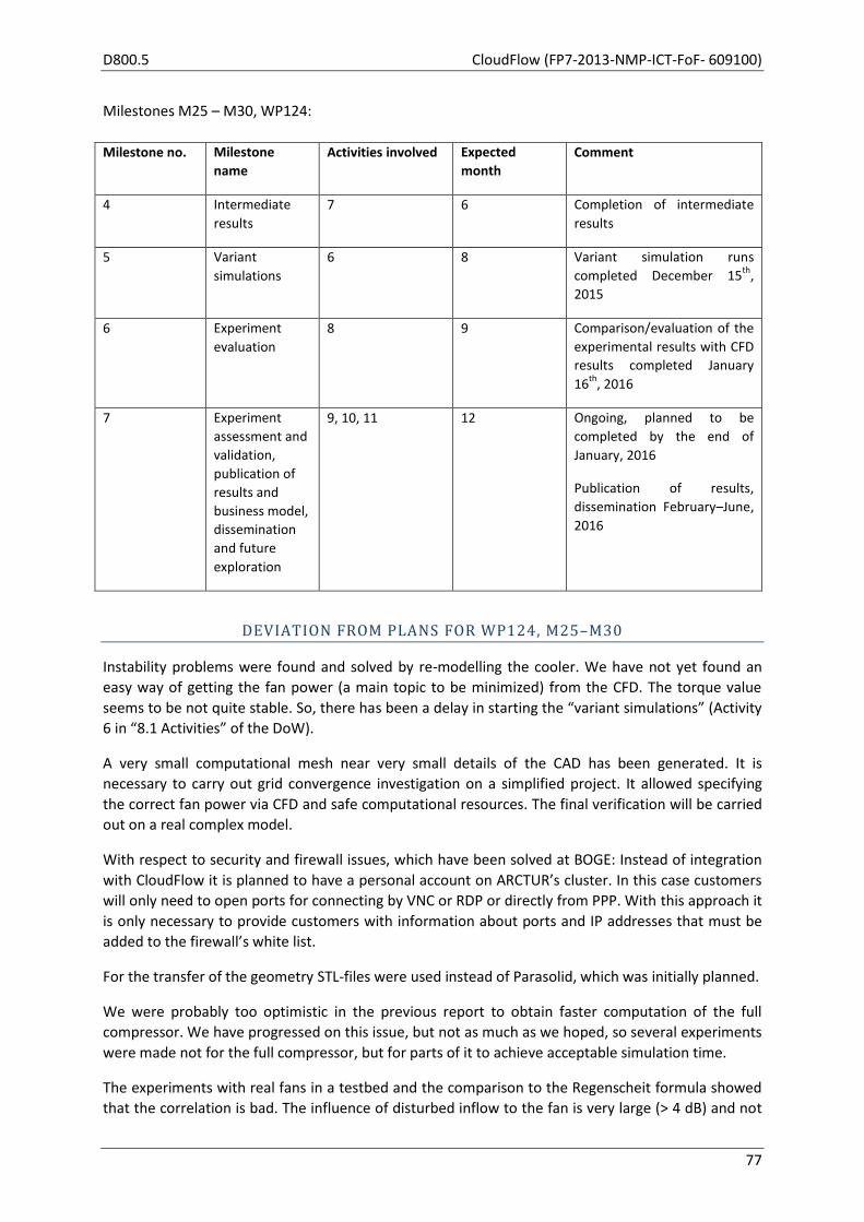
D800.5 CloudFlow (FP7-2013-NMP-ICT-FoF- 609100)
77
Milestones M25 – M30, WP124:
Milestone no. Milestone
name
Activities involved Expected
month
Comment
4 Intermediate
results
7 6 Completion of intermediate
results
5 Variant
simulations
6 8 Variant simulation runs
completed December 15th
,
2015
6 Experiment
evaluation
8 9 Comparison/evaluation of the
experimental results with CFD
results completed January
16th
, 2016
7 Experiment
assessment and
validation,
publication of
results and
business model,
dissemination
and future
exploration
9, 10, 11 12 Ongoing, planned to be
completed by the end of
January, 2016
Publication of results,
dissemination February–June,
2016
DEVIATION FROM PLANS FOR WP124, M25–M30
Instability problems were found and solved by re-modelling the cooler. We have not yet found an
easy way of getting the fan power (a main topic to be minimized) from the CFD. The torque value
seems to be not quite stable. So, there has been a delay in starting the “variant simulations” (Activity
6 in “8.1 Activities” of the DoW).
A very small computational mesh near very small details of the CAD has been generated. It is
necessary to carry out grid convergence investigation on a simplified project. It allowed specifying
the correct fan power via CFD and safe computational resources. The final verification will be carried
out on a real complex model.
With respect to security and firewall issues, which have been solved at BOGE: Instead of integration
with CloudFlow it is planned to have a personal account on ARCTUR’s cluster. In this case customers
will only need to open ports for connecting by VNC or RDP or directly from PPP. With this approach it
is only necessary to provide customers with information about ports and IP addresses that must be
added to the firewall’s white list.
For the transfer of the geometry STL-files were used instead of Parasolid, which was initially planned.
We were probably too optimistic in the previous report to obtain faster computation of the full
compressor. We have progressed on this issue, but not as much as we hoped, so several experiments
were made not for the full compressor, but for parts of it to achieve acceptable simulation time.
The experiments with real fans in a testbed and the comparison to the Regenscheit formula showed
that the correlation is bad. The influence of disturbed inflow to the fan is very large (> 4 dB) and not

CloudFlow (FP7-2013-NMP-ICT-FoF- 609100) D800.5
78
represented in that formula. A Sharland-like formula concerning sound from fans will hardly be
applicable to CFD in general, because the representation of turbulence in different CFD-programs
(Flowvision, Ansys, Fluent, etc.) is not the same. There will be a trial to find a comparison of the
pressure fluctuation computed by CFD on a fan with disturbed inflow (wakes of fan motor holder
arms) with experimental results.
The delay from the first project months was regained rather slowly, so final experiments (with
measurement on the improved sound-reducing enclosure) will happen at the end of January.
DEVIATIONS FROM CRITICAL OBJECTIVES FOR WP124, M25–M30
Delay in starting the “variant simulations” (Activity 6 in “8.1 Activities” of the DoW).
FUTURE PLANS FOR WP124, M25–M30
CAPVIDIA will educate BOGE further on the usage of FlowVision, set up in the ARCTUR
environment.
BOGE will perform different variant simulations.
A demo simulation run will be performed with the dissemination team of UNott at the end of
M26.
CAPVIDIA will attend ISC in Frankfurt and present the CF experiment in cooperation with CF
CC at the end of M27 (done).
CAPVIDIA and BOGE will further investigate a faster way for the CFD computing, by re-
evaluating the CAD data and the related meshing process in order to reduce the computation
time and the required resources (done, by splitting the geometry to sub-domains).
CAPVIDIA will establish a personal account on ARCTUR’s cluster (not in CloudFlow) and install
FlowVision there. Additionally, CAPVIDIA will set up virtual machines that are turned on with every
usage. On such machines the FlowVision pre-post processor will be installed, used for controlling and
preparing the simulations (done).
USED RESOURCES, M25–M30
WP124
BOGE CAPVIDIA Sum
Used PMs M20-M24 1.50 4.30 5.80
Used PMs M25-M30 2.60 2.10 4.70
Available PMs M31 -0.60 -0.10 -0.70
Planned M20-M31 3.50 6.30 9.80
BOGE’s involvement in the M25–M30 time frame was very intensive and devoted to simulation of
different variants.
Capvidia spent significant time on educating and supporting BOGE and tighter integration of
FlowVision into the CloudFlow Portal.
D800.5 CloudFlow (FP7-2013-NMP-ICT-FoF- 609100)
79
2.14 WP125 — Cloud-Based Multiphase Flow Simulation of a Bioreactor
Start M20 End M31 Lead SES-TEC
Participant(s) AVL
OBJECTIVES (AS STATED IN GRANT AGREEMENT)
For the production of medical drugs, products such as proteins, nucleic acids, and living
microorganisms like viruses and bacteria are used. CFD is a simulation approach that can be
successfully used for the characterization of pharmaceutical processes by evaluating system
parameters and their impact on the biopharmaceutical quality. The main challenge is the treatment
of multiphase systems and long process times of several hours. In order to apply CFD in the
development process, a highly optimized workflow and huge computational resources are required.
The aim of the presented project is to adapt the virtual process to cloud-based multiphase
simulations of a bioreactor.
ACTIVITY 125.1: COLLABORATION WITH CLOUDFLOW COMPETENCE CENTRE (AS STATED IN GRANT AGREEMENT)
This activity comprises the collaboration between the participants of this experiment and the
CloudFlow Competence Centre (CF CC) existing partners and covers the following topics:
Collection of user requirements, in collaboration with Task 120.2 of the CloudFlow work packages
Design of the technical integration for the new services with the existing CF infrastructure in collaboration with the design tasks of the technical work packages in CloudFlow, namely WP200, 300, 400 and 500
Definition of new business models, in collaboration with the design task of WP600 of the CloudFlow work plan
ACTIVITY 125.2: INTRODUCTION/INTEGRATION OF THE SOFTWARE INTO HPC/CLOUDFLOW INFRASTRUCTURE (AS STATED IN GRANT AGREEMENT)
The aim of the activity is to install the software and integrate it into the HPC/CloudFlow
infrastructure. First, ARCTUR installs AVL FIRE® on the HPC and the end user (SES-Tec) familiarizes
itself with the HPC/Cloud infrastructure. After that, ARCTUR provides all the required information,
the access and an introduction to the Cloud computing platform via “SSH”. During this phase, the AVL
team supports SES-Tec, ARCTUR and the CF CC on-demand, in order to integrate and install the
software in the most efficient way. SES-Tec will carry out simple tests with already known simple use-
cases and parameters. The aim of the phase is to estimate and evaluate the simulation strategy and
finally to adapt the already existing SES-Tec workflow to the Cloud-based simulation technology. On-
demand, new methods, user-functions and scripts will be written in this task.
ACTIVITY 125.3: SIMPLE CASE INVESTIGATION AND CLOUD BASED SIMULATION (AS STATED IN GRANT AGREEMENT)
In this phase, SES-Tec has to prepare a simple bioreactor simulation, beginning on a desktop PC.
Afterwards, the data will be transferred and the simulation on the HPC/Cloud will be run. The test
case will be a simplified one to reduce calculation time. Difficulties and potential errors will be

CloudFlow (FP7-2013-NMP-ICT-FoF- 609100) D800.5
80
detected and discussed with AVL, ARCTUR and CF CC. The results in this task can be summarized as
follows: evaluation of the executing time, handling of simulation, data transfer, etc.
ACTIVITY 125.4: RUNNING A REAL USE CASE ON THE CLOUD (AS STATED IN GRANT AGREEMENT)
In this step, a real use case simulation will be prepared and run by SES-Tec on the Cloud. Up to five
variants will run in parallel, in order to estimate time and effort for parallel simulations, which are
required for the DoE investigations. Together with the AVL team, the automation of the data
evaluation will be discussed and required scripts will be written by SES-Tec. Once again, the
CloudFlow based workflow will be discussed and improved to save computation time and therewith
calculation costs.
ACTIVITY 125.5: WORKFLOW OPTIMIZATION AND SECOND SIMULATION LOOP (AS STATED IN GRANT AGREEMENT)
The real use case simulation will be re-run by using an optimized workflow created by SES-Tec. In this
case, up to 25 parallel simulations will be run to gain the required data for a DoE analysis. The aim of
this step is an evaluation of the required effort for a DoE simulation, calculation time, data amount,
duration of the data transfer, methodology for the results evaluation, etc. All these data will be
required in the future to enable more competitiveness on the market. This task will be mostly
performed by SES-Tec. The AVL team just supports this task on-demand.
ACTIVITY 125.6: DATA EVALUATION AND REPORT WRITING (AS STATED IN GRANT AGREEMENT)
Finally, the project finishes with a complete documentation of the performed work, a description of
the developed workflow and a tutorial, which can be performed by any CFD user not necessarily
familiar with Cloud computing platforms.
ACTIVITY 125.7: EXPERIMENT ASSESSMENT AND VALIDATION (AS STATED IN GRANT AGREEMENT)
This activity performs a conformance assessment of the implementation of the experiment with the
defined objectives of the experiment and validates it against the user, technical and business
requirements. This activity runs from month 7 to month 12, because then early evaluation can be
done to refine and finally evaluate the improved version of the first implementation. The activity will
be conducted in collaboration with the CF CC.
ACTIVITY 125.8: PROJECT MANAGEMENT (AS STATED IN GRANT AGREEMENT)
The final task includes the project management, which will be carried out by SES-Tec during the
project duration of 12 months. The task includes the following operations: meeting organization,
project tasks controlling, communications between partners, controlling of documentation, etc.
Furthermore, the efforts for the planning and running dissemination activities, during the runtime of
the experiment, have to be reported in the progress report and at the review, after the experiment is
concluded.

D800.5 CloudFlow (FP7-2013-NMP-ICT-FoF- 609100)
81
INTERNAL EXPERIMENT DELIVERABLES DUE M25–M30
At the end of M30 there is no internal experiment deliverable. In the period, the final results of the
bioreactor experiment and the final prototype are prepared for the final deliverable at the end of
M31. This deliverable consists of AVL FIRE® simulation setup data and GridWorker input files and can
be run in the CloudFlow Portal. The prototype is a typical batch type bioreactor configuration with a
common used Rushton impeller and it is working in a wide range of operating conditions. A
parameter study of different aeration rates and rotational speeds can be run by using the simulation
setup. With some minor modification of the setup data, other process parameter variations can also
be performed. In contrast to the first intermediate deliverable (“Bioreactor experiment —
Deliverable iD125.1/INTERNAL 1.1” document), the final prototype will be run in the CloudFlow
Portal and the 2D and 3D simulation results will be evaluated in a web browser.
ACTIVITIES ADDRESSED IN THIS WORK PACKAGE, M25–M30
In the presented project, there are eight activities, as seen in Figure 8.
Figure 9: Activities and the time line
Activity No. 1 includes the collaboration with the CF CC regarding user requirements, the technical
integration of the experiment in the existing CloudFlow infrastructure and the definition of a new
business model. The activity already started at the beginning of the project and lasts until the end
(M12 of bioreactor experiment correlates to CloudFlow project time M31). Activity No. 2 is the
integration into the HPC/Cloud infrastructure and takes 11 months altogether, from M2 until M12
(CloudFlow project M21–M31). This activity includes the AVL-FIRE installation on HPC by ARCTUR and
SES-Tec, all works related to the CloudFlow Portal, GridWorker and Virtual Machines (VMs). Activities
3–6 run parallel to Activity 2 and can be viewed as intermediate steps of Activity 2, which are
required for a successful realization of Activity 2. Activity 7 consists of the experiment assessment
and validation. Activity 8 deals with the project management.
This report is related to the period M25–M30, where Activities 1, 2, 4, 5, 6 and 8 are considered.

CloudFlow (FP7-2013-NMP-ICT-FoF- 609100) D800.5
82
SIGNIFICANT RESULTS, M25–M30
This experiment has provided the following significant results to the project:
A fully integrated workflow in the CloudFlow Portal.
Simulation runs as well as 2D and 3D post-processing can be carried out via a web browser
without the need to download simulation results to a local machine.
MAIN ACTIVITIES IN THIS WORK PACKAGE, M25–M30
Main activities in the period M25–M30 are the following:
1. A125.2 — Introduction/Integration of the software into the HPC/Cloud infrastructure: This
activity includes a full integration of the workflow in the CloudFlow Portal including a post-
processing option of 2D and 3D data in a web browser.
2. A125.4 — Running of the real use-case in the Cloud: This activity includes running a DoE
analysis and the evaluation of the data. Furthermore, the usability of the developed
workflow is tested.
3. A125.5 — Workflow optimization: Functionalities, such as simulation monitoring and stop of
simulation are developed and tested within this activity.
4. A125.6 — Data evaluation/report: Preparation and evaluation of the data for the final report.
Final report writing is the main part of the activity.
5. A125.7 — Experiment assessment and validation: The activity includes data preparation for
the project evaluation and final validation.
PROGRESS OF EXPERIMENT INTERNAL ACTIVITIES
The following table shows the current status of the various activities in detail, as well as the achieved
results of each activity.
Activity No. Description/achieved results Status
Activity 1 — Collaboration with CF CC:
Management Telco — It takes place every month and lasts about two hours. Different topics related to the organization and realization of the project are discussed.
Continuously
Technical Telco — It is held every two weeks, where technical topics related to the integration into the Cloud are discussed.
Continuously
Internal experiment evaluation before London — The evaluation was carried out via the telephone and it is a preparation for the following evaluation in London. Preparation of the data and the presentation were done by SES-Tec and AVL.
Finished
1st
pre-evaluation in London — This pre-evaluation took place in London from 21–25 September 2015. SES-Tec and AVL were presented.
Finished
Business model — Telco with CARSA, AVL and SES-Tec regarding a Cloud specific business model after the project (November–December 2015). Data evaluation and preparation of the reports regarding the business model is done by SES-Tec and AVL.
Finished
Activity 2 — Integration into HPC/Cloud:
VM — Installation of a virtual machine by ARCTUR, final initialization (July 2015).
Finished
Web-server — Installation of an Apache web server by ARCTUR (July 2015). Finished

D800.5 CloudFlow (FP7-2013-NMP-ICT-FoF- 609100)
83
GUI — Development of a web-based GUI (PHP and HTML) for the first evaluation in London (August 2015).
Finished
Run of the simulation, monitoring, post-processing in the Cloud — Integration of the scripts in the Cloud and testing (August 2015).
Finished
Discussion about SES-Tec workflow integration into the CloudFlow Portal — Analysis of the workflow integration is still in progress. Involved partners are SINTEF, DFKI, Fraunhofer, ARCTUR and SES-Tec (September 2015).
Finished
Integration into the CloudFlow Portal — Run of first tests in the CloudFlow Portal, test of GridWorker integration in Cloud, which is provided by Fraunhofer (October 2015).
Finished
3D post-processing in the Cloud — Preparation of scripts for the CGNS file writing. Testing of remote post-processing tool developed by Fraunhofer. The required macros are written by AVL. Implementation in Cloud is done by SES-Tec and Fraunhofer (November 2015).
Finished
2D post-processing — Integration and testing of Fraunhofer 2D post- processing tool in web browser. Preparation of required scripts, file formats, workflows, and test of these. Involved partners are SINTEF, DFKI, Fraunhofer, AVL and SES-Tec (December 2015).
Finished
Integration of simulation monitoring and stop functions — Basics functions are prepared by Fraunhofer. Tests are carried out by SES-Tec. AVL has supported SES-Tec regarding AVL-FIRE functionalities (December 2015 – January 2016).
In progress
Activity 4 — Running of real case in the Cloud:
Running of a DoE analysis — A real case simulation is carried out during this activity by SES-Tec. Namely, several process parameter are varied, such as aeration rate and impeller speed, where each simulation is executed in parallel using GridWorker.
Finished
Activity 5 — Workflow optimization
Improvement of the workflow: This activity includes optimization of the workflow. The scripts will be re-written and optimized. All steps are discussed together with Fraunhofer and possible code/workflow modification are performed (November–December 2015). AVL has supported SES-Tec for running scripts and macros optimization.
Finished
Activity 6 — Data evaluation/report
During this activity, simulation data are evaluated and prepared for the final report. Final report writing finalized the activity (December 2015–January 2016). Involved partners are SES-Tec and AVL.
In progress
Activity 7 — Experiment assessment and validation
Data evaluation, preparation of the test cases for the assessment and live demonstration, validation of the experiment, presentation via telephone conference, (December 2015).
Finished
Preparation of the data and presentation for final assessment and demonstration in February 2016 (January 2016). Involved partners are SES-Tec and AVL.
In progress
Table 1: Status and results of each activity
PROGRESS BEYOND STATE OF THE ART
In contrast to other Cloud providers, the integration into the CloudFlow Portal is mainly based on a
particular use-case (e.g. the bioreactor). The simulation background knowledge of an end user is
therewith reduced to a minimum. This means that a huge number of possible customers, which
could use the technology and are inexperienced, could be integrated easily and educated for this
kind of simulations.
CloudFlow (FP7-2013-NMP-ICT-FoF- 609100) D800.5
84
INTEGRATION IN THE CLOUDFLOW INFRASTRUCTURE
The developed workflow in the experiment is integrated completely into the CloudFlow Portal,
except the pre-processing step, which has to be carried out on a local machine. After a local
preparation of all simulation setup files (AVL-FIRE and GridWorker files), the data will be uploaded to
the GSS in the CloudFlow Portal. After data upload, GridWorker can be executed and thereby all
predefined simulations. When the simulations are finished, all simulation results will be saved in the
GSS. There is no need to download the data to a local machine. The 3D as well as the 2D data post-
processing can be done directly in the web browser by using web-based tools, developed by
Fraunhofer. Alternatively, the simulation results can be downloaded and evaluated on a local
machine.
EXPERIMENT BUSINESS MODEL AND EXPERIMENT IMPACT
In the period M25–M30, the business model was reviewed together with CARSA. The exploitation
plans of the experiment were developed, which include an estimation of application numbers in the
cloud, market, market size, number of clients, market share, number of new jobs, number of existing
and expected new clients, expected total income and the price of the cloud computing.
On the basis of the CloudFlow project, SES-Tec is able to extend their portfolio by offering a huge
number of simulation variants in a shorter calculation time. SES-Tec benefits from the simulation
resources (in particular the huge number of CPUs), which can be used on-demand without any
additional internal fix costs. Huge computational resources are required in the case of a DoE analysis,
where a huge number of simulation variants can be carried out parallel. Furthermore, the self-
developed workflow and the self-integration in the CloudFlow Portal bring SES-Tec additional
advantages on the market over their competitors.
AVL expects an increasing number of sold licenses in the cloud in the next five years, because of the
AVL-FIRE integration into the CloudFlow Portal.
EXPERIMENT DISSEMINATION
In the period M25–M30, SES-Tec has visited two different exhibitions (Elmia Subcontractor 2015,
Sweden and the International Machinery and Plant Engineering Forum in Vienna, 2015), where the
CloudFlow project and cloud computing in general have been introduced. Furthermore, in September
2015, SES-Tec has visited one of their customers (Vogelbusch Biopharma), which is also a bioreactor
manufacturer. During this meeting, the CloudFlow project and cloud computing were introduced in
detail.
MILESTONES APPLICABLE TO THIS WORK PACKAGE, M25–M30
There are no milestones in the period M25–M30. The next milestone is at the end of project time,
M31, where the final prototype and results as well as the report have to be delivered.
DEVIATION FROM PLANS, M25–M30
There are no deviations.
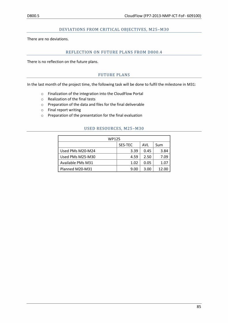
D800.5 CloudFlow (FP7-2013-NMP-ICT-FoF- 609100)
85
DEVIATIONS FROM CRITICAL OBJECTIVES, M25–M30
There are no deviations.
REFLECTION ON FUTURE PLANS FROM D800.4
There is no reflection on the future plans.
FUTURE PLANS
In the last month of the project time, the following task will be done to fulfil the milestone in M31:
o Finalization of the integration into the CloudFlow Portal
o Realization of the final tests
o Preparation of the data and files for the final deliverable
o Final report writing
o Preparation of the presentation for the final evaluation
USED RESOURCES, M25–M30
WP125
SES-TEC AVL Sum
Used PMs M20-M24 3.39 0.45 3.84
Used PMs M25-M30 4.59 2.50 7.09
Available PMs M31 1.02 0.05 1.07
Planned M20-M31 9.00 3.00 12.00
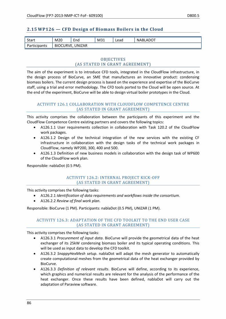
CloudFlow (FP7-2013-NMP-ICT-FoF- 609100) D800.5
86
2.15 WP126 — CFD Design of Biomass Boilers in the Cloud
Start M20 End M31 Lead NABLADOT
Participants BIOCURVE, UNIZAR
OBJECTIVES (AS STATED IN GRANT AGREEMENT)
The aim of the experiment is to introduce CFD tools, integrated in the CloudFlow infrastructure, in the design process of BioCurve, an SME that manufactures an innovative product: condensing biomass boilers. The current design process is based on the experience and expertise of the BioCurve staff, using a trial and error methodology. The CFD tools ported to the Cloud will be open source. At the end of the experiment, BioCurve will be able to design virtual boiler prototypes in the Cloud.
ACTIVITY 126.1 COLLABORATION WITH CLOUDFLOW COMPETENCE CENTRE (AS STATED IN GRANT AGREEMENT)
This activity comprises the collaboration between the participants of this experiment and the CloudFlow Competence Centre existing partners and covers the following topics:
A126.1.1 User requirements collection in collaboration with Task 120.2 of the CloudFlow work packages.
A126.1.2 Design of the technical integration of the new services with the existing CF infrastructure in collaboration with the design tasks of the technical work packages in CloudFlow, namely WP200, 300, 400 and 500.
A126.1.3 Definition of new business models in collaboration with the design task of WP600 of the CloudFlow work plan.
Responsible: nablaDot (0.5 PM).
ACTIVITY 126.2: INTERNAL PROJECT KICK-OFF (AS STATED IN GRANT AGREEMENT)
This activity comprises the following tasks:
A126.2.1 Identification of data requirements and workflows inside the consortium.
A126.2.2 Review of final work plan.
Responsible: BioCurve (1 PM). Participants: nablaDot (0.5 PM), UNIZAR (1 PM).
ACTIVITY 126.3: ADAPTATION OF THE CFD TOOLKIT TO THE END USER CASE (AS STATED IN GRANT AGREEMENT)
This activity comprises the following tasks:
A126.3.1 Procurement of input data. BioCurve will provide the geometrical data of the heat exchanger of its 25kW condensing biomass boiler and its typical operating conditions. This will be used as input data to develop the CFD toolkit.
A126.3.2 SnappyHexMesh setup. nablaDot will adapt the mesh generator to automatically create computational meshes from the geometrical data of the heat exchanger provided by BioCurve.
A126.3.3 Definition of relevant results. BioCurve will define, according to its experience, which graphics and numerical results are relevant for the analysis of the performance of the heat exchanger. Once these results have been defined, nablaDot will carry out the adaptation of Paraview software.

D800.5 CloudFlow (FP7-2013-NMP-ICT-FoF- 609100)
87
A126.3.4 OpenFOAM setup. nablaDot will prepare the OpenFOAM solver through the selection and provision of the appropriate sub-models for the simulation of the heat exchanger.
A126.3.5 Paraview setup. nablaDot will adapt Paraview software to easily post-process the obtained results. The relevant results defined by BioCurve in Task 2.3 will be automatically processed by Paraview in the format indicated by BioCurve through the use of scripts.
Responsible: nablaDot (4.5 PM). Participants: BioCurve (1 PM).
ACTIVITY 126.4: PREPARATION OF THE CLOUDFLOW INFRASTRUCTURE (AS STATED IN GRANT AGREEMENT)
UNIZAR will install the necessary Cloud middleware, based on CloudFlow project tools on top of its OpenStack Cloud computing infrastructure. nablaDot will port the CFD software to the CloudFlow infrastructure. This activity comprises the following tasks:
A126.4.1 Analysis and training of CloudFlow tools. UNIZAR will receive detailed technical documentation and training on how to use, install and configure the different CloudFlow tools both at user level and at sysadmin level to integrate them with their own computing resources.
A126.4.2 Integration of CloudFlow tools in UNIZAR computing resources. Iterative work will be carried out for the integration of the different pieces of software needed to be installed at UNIZAR computing resources to be CloudFlow compatible. Support from CloudFlow experts will be required to complete the whole integration.
A126.4.3 Porting the CFD software to the CloudFlow environment. nablaDot will port the CFD tools developed to the CloudFlow environment with the support of UNIZAR.
A126.4.4 Development of a user-friendly interface. nablaDot will develop a user-friendly environment to use the CFD tools by non-expert users. This environment will be based on a web application or a virtual desktop application, depending on which solution is better adapted to the CloudFlow infrastructure. UNIZAR will provide computer support to nablaDot in this task.
A126.4.5 Test and validation of CloudFlow integrated tools. Once the full computing infrastructure is integrated with CloudFlow, the CFD software is ready and its user interface developed, a series of test will be carried out in order to ensure the proper operation of the new tools, as well as to perform a basic validation. Once it is validated, Activity 126.5 (validation of CFD results) will start.
Responsible: UNIZAR (5 PM). Participants: nablaDot (4 PM).
ACTIVITY 126.5: VALIDATION OF THE CFD RESULTS (AS STATED IN GRANT AGREEMENT)
The results of the CFD simulations will be validated against empirical measurements. The following tasks are considered in this activity:
A126.5.1 Measurements. BioCurve will carry out measurements of the relevant parameters of the performance of the heat exchanger (mass flow, composition and temperature of gases at the inlet and outlet of the heat exchanger, pressure losses of gases in the heat exchanger and mass flow and temperature of the water at the inlet and outlet) for different operating conditions of the biomass boiler.
A126.5.2 CFD validation. nablaDot, using the CloudFlow infrastructure, will simulate the heat exchanger for these operating conditions, and the results obtained will be compared with the measurements.
CloudFlow (FP7-2013-NMP-ICT-FoF- 609100) D800.5
88
A126.5.3 Sensitivity analysis. A sensitivity analysis will be carried out to determine the influence of parameters such as mesh refinement or turbulence models. The solver will be adjusted to the configuration that provides the best results.
Responsible: BioCurve (2 PM). Participants: nablaDot (2 PM).
ACTIVITY 126.6: INTEGRATION OF THE WORKFLOW IN THE NEW DESIGN PROCESS (AS STATED IN GRANT AGREEMENT)
In this task, BioCurve will design a virtual prototype of a heat exchanger for its 25 kW condensing biomass boiler using the engineering tools in the Cloud.
A126.6.1 Training on toolkit & CFD use. nablaDot will provide training and support to BioCurve to use the CFD tools in the Cloud. At the end of this task, BioCurve will be able to run independently CFD simulations in the Cloud.
A126.6.2 Design of virtual prototypes. BioCurve will test virtual prototypes of the heat exchanger of its 25 kW boiler to improve its current design.
A126.6.3 User interface feedback & improvements. BioCurve will provide feedback about the user interface developed, as well as suggestions to refine its performance. nablaDot will implement improvements to the user interface according to the feedback received from BioCurve.
Responsible: BioCurve (3.5 PM). Participants: nablaDot (1 PM).
ACTIVITY 126.7: EXPERIMENT ASSESSMENT AND VALIDATION (AS STATED IN GRANT AGREEMENT)
This activity performs an assessment of the conformance of the implementation of the experiment with the stated goals of the experiment and validates the experiments against the user, technical and business requirements. The activity runs from month 7 to month 12 so early evaluation can be done to refine and finally evaluate the improved version of a first implementation. The activity will be conducted in collaboration with the CloudFlow Competence Centre.
Responsible: nablaDot (0.5 PM).
ACTIVITY 126.8: DISSEMINATION AND FUTURE EXPLOITATION (AS STATED IN GRANT AGREEMENT)
This activity addresses the exploitation of the case after the CloudFlow project and its dissemination. The following tasks have been considered in this activity:
A126.8.1 Specification of dissemination tasks. A detailed planning of the dissemination tasks will be prepared.
A126.8.2 Workshop organization. Activities concerning the organization of the final workshop (venue, dates, promotion, etc.)
A126.8.3 Business day organization. UNIZAR will organize a business day where the CloudFlow approach will be presented as a success story of adoption of CFD tools by an unexperienced company.
A126.8.4 Other dissemination tasks. All partners will present on their respective websites their participation in this CloudFlow experiment. Also, at the end of the project, the publication of this experiment in regional newspaper is foreseen.
A126.8.5 Other exploitation tasks. nablaDot and UNIZAR will address directly enterprises that can be potential users of CloudFlow.
D800.5 CloudFlow (FP7-2013-NMP-ICT-FoF- 609100)
89
A126.8.6 Evaluation of experiment and business model. This task will be managed by the CloudFlow Competence Centre. A cost-benefit analysis of the new design process will be carried out. The case will be critically examined to seek possible improvements in the implementation cycle. Additional opportunities will be identified for the members of the consortium to which the present business model can be exported.
Responsible: nablaDot (1 PM). Participants: BioCurve (1 PM), UNIZAR (0.5 PM).
INTERNAL EXPERIMENT DELIVERABLES DUE M25–M30
Three internal experiment deliverables were planned for this period:
I126.3 Preparation of CloudFlow infrastructure (Experiment month 6, CloudFlow month 25)
I126.4 Validation of CFD results (Experiment month 8, CloudFlow month 27)
I126.5 Integration of a new workflow in the design process (Experiment month 11, CloudFlow month 30)
Only Deliverable I126.4 has been produced and delivered in the reporting period. The other two deliverables correspond to activities that are not yet finished though in an advanced state. For this reason, these deliverables have not been elaborated yet.
ACTIVITIES ADDRESSED IN THIS WORK PACKAGE, M25–M30
Activity 126.4: Preparation of the CloudFlow infrastructure
o Analysis and training of CloudFlow tools
o Integration of CloudFlow tools in UNIZAR-BIFI
o Porting the CFD tools to the Cloud environment
o Development of the user interface
o Test of the CloudFlow infrastructure
Activity 126.5: Validation of the CFD results
o Measurements
o CFD validation
o Sensitivity analysis
Activity 126.6: Integration of the workflow in the design process
o Training on toolkit & CFD use
o Design of virtual prototypes
o User interface feedback & improvements
SIGNIFICANT RESULTS, M25–M30
The significant results of the experiment in this reporting period have been:
Successful validation of the CFD results with measurements.
Development and implementation of the new workflow for the design of the heat
exchangers. The developed workflow is really user-friendly. The setup of each case is very
simple and it is highly automated, even the post-processing of results.
Successful training of BioCurve’s staff for the use of the new workflow.
BioCurve’s staff are able to use the new workflow by themselves. They have already tested
some virtual prototypes.
MAIN ACTIVITIES IN THIS WORK PACKAGE, M25–M30

CloudFlow (FP7-2013-NMP-ICT-FoF- 609100) D800.5
90
PROGRESS OF EXPERIMENT INTERNAL ACTIVITIES
In this period, the following activities have been developed: preparation of the CloudFlow
infrastructure, validation of the CFD results and integration of the workflow in the design process.
The validation of the CFD results has been completed, whereas the other two activities are in an
advanced state.
Regarding the preparation of the CloudFlow infrastructure, during this period the OpenStack Cloud
Infrastructure has been upgraded with new resources in order to resolve some RAM limitations
found during some OpenFOAM simulation tests. UNIZAR has been giving close support to nablaDot
in order to debug possible problems related to cloud instances, images, data stored, and all kind of
issues related to integration of the simulation in the cloud infrastructure.
Furthermore, a new proxy machine has been deployed in order to solve some authentication issues
due to incompatibilities of the academic certificates used by our services to encrypt the https
connection and validate the identity. This new set up has also made it possible to integrate the
authentication of a user from the CloudFlow Portal, being able to use both computing resources and
storage thanks to a new token obtained from UNIZAR’s local keystone, which is then used by the
WFM.
In the last part of the period, the attendance to the 2nd Wave CloudFlow Code Camp in Dresden was
really useful as we could clearly identify all the possible issues that had delayed for months the
integration of our experiment in the CloudFlow infrastructure. This facilitated a combined work of
CloudFlow developers together with nablaDot’s and UNIZAR’s developers.
Currently the development of the services is being carried out as well as its integration and testing
with the WFM in order to deploy the final use case explained by nablaDot.
Regarding the validation of CFD results, the internal deliverable “I126.4 Validation of CFD results”
describes in detail the work done in this activity. Measurements have been carried out for three
operation modes of the biomass boiler. These operation modes were simulated and the CFD results
were compared to the measurements. This comparison has been successful. The differences
between the flue gas and water outlet temperatures calculated and measured are lower than 3%.
One of the user requirements set in the experiment has been met with this successful validation.
The activity integration of the workflow in the design process (which entails the following tasks:
training on toolkit & CFD use, design of virtual prototypes and user interface feedback &
improvements) is in an advanced state. The level of execution for this activity is estimated at 70% at
the end of December. A user-friendly workflow has been designed and implemented in the
CloudFlow environment. In order to be an ease-of-use tool, significant efforts have been dedicated to
automate all the processes, even the post-processing of the results. BioCurve’s staff have been
trained in the use of the workflow and they are able to simulate virtual heat exchangers for their
biomass boilers. Currently, BioCurve’s staff are testing virtual prototypes with the purpose of
reducing the volume of the heat exchanger in the biomass boiler model of 25 kW. Due to these
advances, some of the user requirements (ease of use of the workflow and ability to simulate virtual
boilers) set for the experiment have almost been achieved.
nablaDot participated in the CloudFlow review meeting in London (September 2015) and, as
mentioned above, nablaDot and UNIZAR attended the 2nd Wave CloudFlow Code Camp in Dresden
(November 2015), organized by the CloudFlow consortium and partners of the 2nd Wave

D800.5 CloudFlow (FP7-2013-NMP-ICT-FoF- 609100)
91
experiments, with the purpose of supporting the integration of experiments in the CloudFlow
infrastructure. Additionally, internal meetings have been organized:
Two meetings with all partners to review the state of the activities and tasks of the
experiment.
Some meetings between nablaDot and BioCurve to treat issues regarding the activity
validation of the CFD results and to carry out the training of Biocurve’s staff in the use of the
new workflow.
Some meetings between nablaDot and UNIZAR to coordinate the tasks involved in the
preparation of the CloudFlow infrastructure.
PROGRESS BEYOND STATE OF THE ART
In this experiment, the state of the art is defined as:
Incapability of BioCurve to use CFD tools
The biomass boiler of 25 kW of BioCurve is oversized
At this stage of the project, BioCurve’s staff are able to use CFD tools by themselves, advancing the
first part beyond the state of the art. Currently, BioCurve’s staff are using the new workflow in the
Cloud to calculate improved designs of the biomass boiler of 25 kW. We expect to obtaine a reduced
size of this biomass boiler at the end of the project.
INTEGRATION IN THE CLOUDFLOW INFRASTRUCTURE
A considerable effort has been dedicated to the integration of the experiment in the CloudFlow
infrastructure. UNIZAR and nablaDot have worked together in this task during this reporting period.
Also, UNIZAR and nablaDot attended the 2nd Wave CloudFlow Code Camp, organized with the aim of
supporting the integration of 2nd Wave Experiments in the CloudFlow infrastructure. The level of
execution of this task at the end of the reporting period is estimated at 80%.
EXPERIMENT BUSINESS MODEL AND EXPERIMENT IMPACT
The following tasks have been carried out with CARSA:
The customer development phase. The objective of this task has been the validation of the
business model defined previously under a customer perspective and through a
questionnaire prepared by CARSA. BioCurve and an actual customer of nablaDot answered to
this questionnaire.
An assessment of the product, its market and its impact. In order to do this, nablaDot and
UNIZAR filled out an exploitation justification template, prepared by CARSA.
EXPERIMENT DISSEMINATION
BioCurve participated in the ExpoBiomasa exhibition in Valladolid (Spain), 22–24 September 2015.
This is the most important exhibition of biomass boilers in Spain, where a complete range of wood
heating appliances, wood fuel types and wood fuels chains can be found. BioCurve exhibited their
condensing biomass boilers, and, further, disseminated the CloudFlow project, distributing
CloudFlow brochures and explaining the concept and objectives of this experiment.
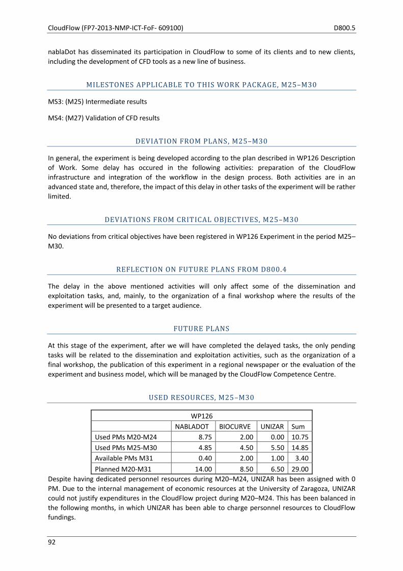
CloudFlow (FP7-2013-NMP-ICT-FoF- 609100) D800.5
92
nablaDot has disseminated its participation in CloudFlow to some of its clients and to new clients,
including the development of CFD tools as a new line of business.
MILESTONES APPLICABLE TO THIS WORK PACKAGE, M25–M30
MS3: (M25) Intermediate results
MS4: (M27) Validation of CFD results
DEVIATION FROM PLANS, M25–M30
In general, the experiment is being developed according to the plan described in WP126 Description
of Work. Some delay has occured in the following activities: preparation of the CloudFlow
infrastructure and integration of the workflow in the design process. Both activities are in an
advanced state and, therefore, the impact of this delay in other tasks of the experiment will be rather
limited.
DEVIATIONS FROM CRITICAL OBJECTIVES, M25–M30
No deviations from critical objectives have been registered in WP126 Experiment in the period M25–
M30.
REFLECTION ON FUTURE PLANS FROM D800.4
The delay in the above mentioned activities will only affect some of the dissemination and
exploitation tasks, and, mainly, to the organization of a final workshop where the results of the
experiment will be presented to a target audience.
FUTURE PLANS
At this stage of the experiment, after we will have completed the delayed tasks, the only pending
tasks will be related to the dissemination and exploitation activities, such as the organization of a
final workshop, the publication of this experiment in a regional newspaper or the evaluation of the
experiment and business model, which will be managed by the CloudFlow Competence Centre.
USED RESOURCES, M25–M30
WP126
NABLADOT BIOCURVE UNIZAR Sum
Used PMs M20-M24 8.75 2.00 0.00 10.75
Used PMs M25-M30 4.85 4.50 5.50 14.85
Available PMs M31 0.40 2.00 1.00 3.40
Planned M20-M31 14.00 8.50 6.50 29.00
Despite having dedicated personnel resources during M20–M24, UNIZAR has been assigned with 0
PM. Due to the internal management of economic resources at the University of Zaragoza, UNIZAR
could not justify expenditures in the CloudFlow project during M20–M24. This has been balanced in
the following months, in which UNIZAR has been able to charge personnel resources to CloudFlow
fundings.
D800.5 CloudFlow (FP7-2013-NMP-ICT-FoF- 609100)
93
2.16 WP127 — Automobile Light Design: Thermal Simulation of Lighting Systems
Start M20 End M31 Lead BTECHC
Participants CSUC
OBJECTIVES (AS STATED IN GRANT AGREEMENT)
The thermal simulation of lighting systems requires the use of complex methodologies and supercomputing systems. The objective is to simplify the methodology to simulate, using free software, namely OpenFOAM and Code_Aster, heat extraction in thermal sources through numerical methods, and specifically to analyse automobile light designs. To this aim CloudFlow tools (WFM, WFE, etc.) will be used to simplify the whole process by automating the workflow of the HPC work.
ACTIVITY 127.1: COLLABORATION WITH CLOUDFLOW COMPETENCE CENTRE (AS STATED IN GRANT AGREEMENT)
This activity comprises collaboration between the participants of this experiment and the CloudFlow Competence Centre's existing partners and covers the following topics:
User requirements collection in collaboration with Task 120.2 of the CloudFlow work packages.
Design of the technical integration of the new services with the existing CF infrastructure in collaboration with the design tasks of the technical work packages in CloudFlow, namely WP200, 300, 400 and 500.
Definition of new business models in collaboration with the design task of WP600 of CloudFlow.
ACTIVITY 127.2: CLOUDFLOW INFRASTRUCTURE KNOWLEDGE (AS STATED IN GRANT AGREEMENT)
This activity comprises:
Learning about the CloudFlow infrastructure (CSUC & CF CC)
Workflow and block edition (CSUC)
Decision for CloudFlow Portal deployment (CSUC & CF CC)
Virtual machines deployment (CSUC)
CloudFlow applications installation and implementation to CSUC’s HPC resources (CSUC)
ACTIVITY 127.3: SIMULATION IN THE CLOUD (AS STATED IN GRANT AGREEMENT)
During this activity three sub-activities will be carried out:
Solvers: OpenFOAM and Code_Aster model creation (BTECHC). OpenFOAM simulation (BTECHC). Code_Aster simulation (BTECHC). Launch Jobs in HPC Platform with the CloudFlow Portal (BOTH). Model Validation (BTECHC).
Pre-process: Mesh definition (BTECHC). Automatic meshing and parallel meshing (BOTH). Boundary conditions parametrization (BTECHC). Launch meshing processes to the HPC Platform with the CloudFlow Portal (BOTH). Launch multiple parameterized cases with the CloudFlow Portal (BOTH).
CloudFlow (FP7-2013-NMP-ICT-FoF- 609100) D800.5
94
Post-Process: Post-process definition (BTECHC). CFD to structural definition (BTECHC). CFD to structural mapping with Python scripting (CSUC). Automatic post-processing scripts (BTECHC). Remote visualisation comparative and final decision (CSUC). Remote desktop integration in the CloudFlow Portal (CSUC).
ACTIVITY 127.4&6: INTERMEDIATE AND FINAL EVALUATION (AS STATED IN GRANT AGREEMENT)
The CloudFlow Competence Centre will evaluate the experiment ‘Automobile light design: thermal simulation of lighting systems’.
ACTIVITY 127.5: CLOUDFLOW INFRASTRUCTURE IMPLEMENTATION: WORKFLOWS IN THE CLOUD
(AS STATED IN GRANT AGREEMENT)
This activity comprises:
Integration of services and applications in the CloudFlow infrastructure. Job Submission, File Manager, Accounting, Workflow Editor, Remote Visualisation (CSUC).
New Model Creation (BTECHC).
Launch Workflows with the CloudFlow Portal (BOTH).
Feed-back, lessons learned and improvements (BOTH).
ACTIVITY 127.7: EXPERIMENT ASSESSMENT AND VALIDATION (AS STATED IN GRANT AGREEMENT)
This activity performs an assessment of the conformance of the implementation of the experiment with the stated goals of the experiment and validates the experiments against the user, technical and business requirements. The activity runs from month 7 to month 12 so early evaluation can be done to refine and finally evaluate the improved version of a first implementation. The activity will be conducted in collaboration with the CF CC.
ACTIVITY127.8: DISSEMINATION AND FUTURE EXPLOITATION (AS STATED IN GRANT AGREEMENT)
This activity covers efforts for planning and running dissemination activities during the runtime of the experiment to be reported in the progress reports and at the review after the experiment concluded.
Several blog entries and an article have been published in the CSUC website.
http://www.csuc.cat/en/new/csuc-s-participation-in-the-european-project-cloudflow
http://blog.csuc.cat/?tag=cloudflow
INTERNAL EXPERIMENT DELIVERABLES DUE M25–M30
No internal experiment deliverables were planned in the reporting period.
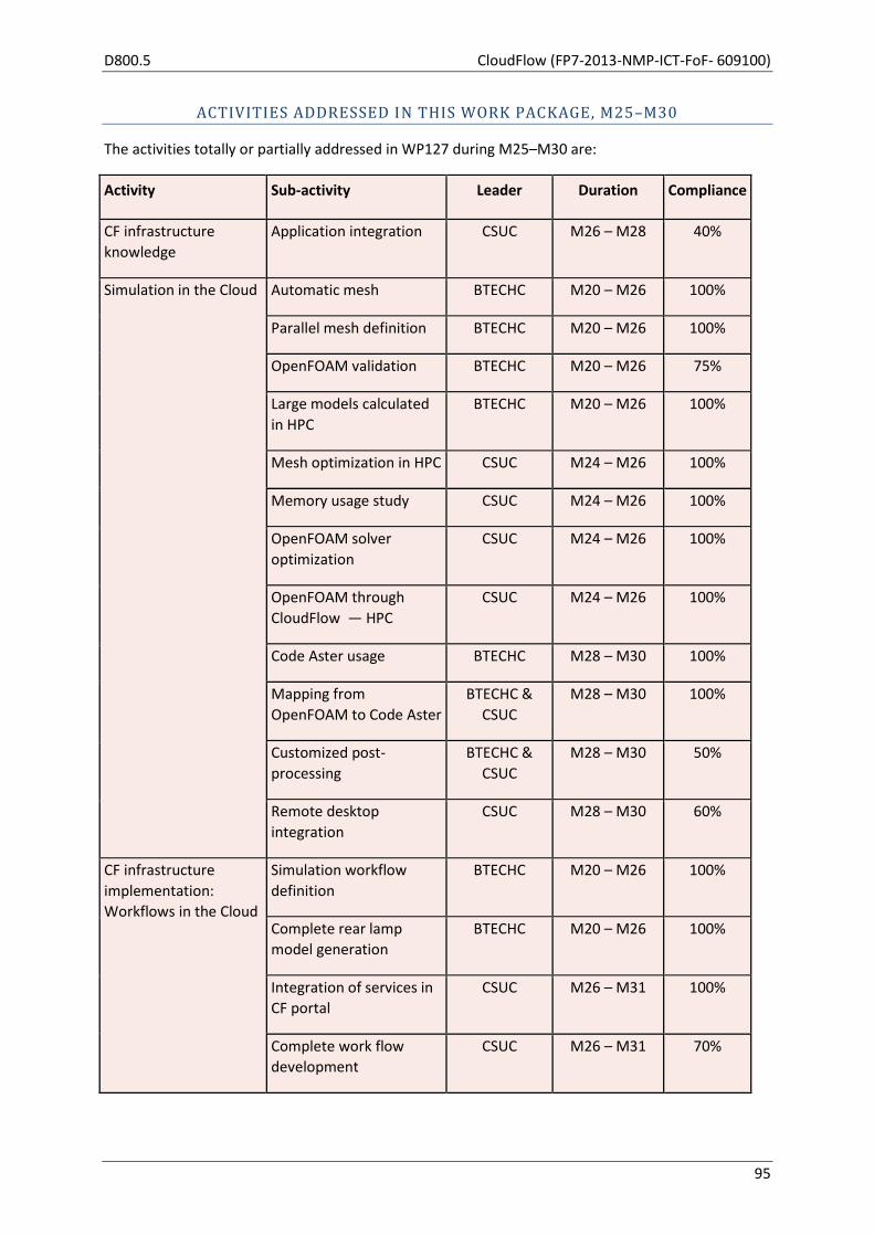
D800.5 CloudFlow (FP7-2013-NMP-ICT-FoF- 609100)
95
ACTIVITIES ADDRESSED IN THIS WORK PACKAGE, M25–M30
The activities totally or partially addressed in WP127 during M25–M30 are:
Activity Sub-activity Leader Duration Compliance
CF infrastructure
knowledge
Application integration CSUC M26 – M28 40%
Simulation in the Cloud Automatic mesh BTECHC M20 – M26 100%
Parallel mesh definition BTECHC M20 – M26 100%
OpenFOAM validation BTECHC M20 – M26 75%
Large models calculated
in HPC
BTECHC M20 – M26 100%
Mesh optimization in HPC CSUC M24 – M26 100%
Memory usage study CSUC M24 – M26 100%
OpenFOAM solver
optimization
CSUC M24 – M26 100%
OpenFOAM through
CloudFlow — HPC
CSUC M24 – M26 100%
Code Aster usage BTECHC M28 – M30 100%
Mapping from
OpenFOAM to Code Aster
BTECHC &
CSUC
M28 – M30 100%
Customized post-
processing
BTECHC &
CSUC
M28 – M30 50%
Remote desktop
integration
CSUC M28 – M30 60%
CF infrastructure
implementation:
Workflows in the Cloud
Simulation workflow
definition
BTECHC M20 – M26 100%
Complete rear lamp
model generation
BTECHC M20 – M26 100%
Integration of services in
CF portal
CSUC M26 – M31 100%
Complete work flow
development
CSUC M26 – M31 70%
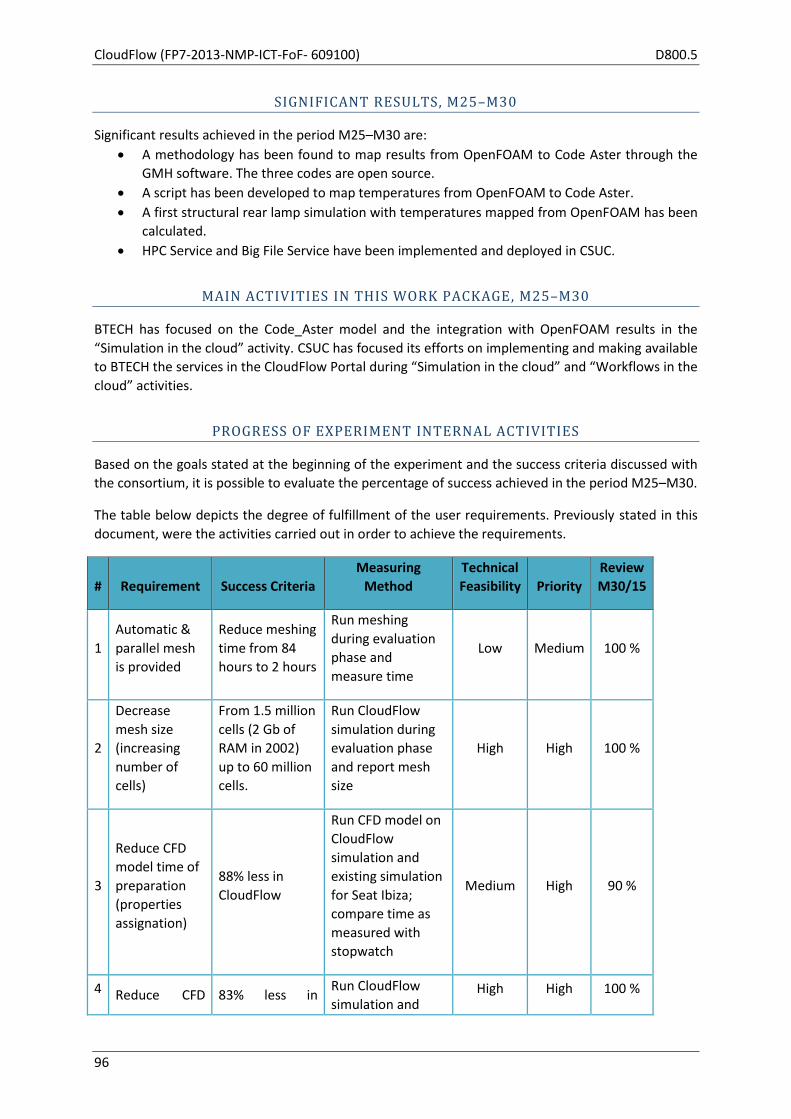
CloudFlow (FP7-2013-NMP-ICT-FoF- 609100) D800.5
96
SIGNIFICANT RESULTS, M25–M30
Significant results achieved in the period M25–M30 are:
A methodology has been found to map results from OpenFOAM to Code Aster through the
GMH software. The three codes are open source.
A script has been developed to map temperatures from OpenFOAM to Code Aster.
A first structural rear lamp simulation with temperatures mapped from OpenFOAM has been
calculated.
HPC Service and Big File Service have been implemented and deployed in CSUC.
MAIN ACTIVITIES IN THIS WORK PACKAGE, M25–M30
BTECH has focused on the Code_Aster model and the integration with OpenFOAM results in the
“Simulation in the cloud” activity. CSUC has focused its efforts on implementing and making available
to BTECH the services in the CloudFlow Portal during “Simulation in the cloud” and “Workflows in the
cloud” activities.
PROGRESS OF EXPERIMENT INTERNAL ACTIVITIES
Based on the goals stated at the beginning of the experiment and the success criteria discussed with
the consortium, it is possible to evaluate the percentage of success achieved in the period M25–M30.
The table below depicts the degree of fulfillment of the user requirements. Previously stated in this
document, were the activities carried out in order to achieve the requirements.
# Requirement Success Criteria
Measuring
Method
Technical
Feasibility Priority
Review
M30/15
1
Automatic &
parallel mesh
is provided
Reduce meshing
time from 84
hours to 2 hours
Run meshing
during evaluation
phase and
measure time
Low Medium 100 %
2
Decrease
mesh size
(increasing
number of
cells)
From 1.5 million
cells (2 Gb of
RAM in 2002)
up to 60 million
cells.
Run CloudFlow
simulation during
evaluation phase
and report mesh
size
High High 100 %
3
Reduce CFD
model time of
preparation
(properties
assignation)
88% less in
CloudFlow
Run CFD model on
CloudFlow
simulation and
existing simulation
for Seat Ibiza;
compare time as
measured with
stopwatch
Medium High 90 %
4 Reduce CFD 83% less in Run CloudFlow
simulation and High High 100 %

D800.5 CloudFlow (FP7-2013-NMP-ICT-FoF- 609100)
97
Solver time CloudFlow existing simulation
for Seat Ibiza;
compare CFD
solver time as
measured with
stopwatch
5
Reduce post-
processing
time in CFD
96% less in
CloudFlow
Conduct CFD post-
processing with
CloudFlow
simulation and
existing simulation
for Seat Ibiza,
compare time as
measured with
stopwatch
Medium Medium 50 %
Regarding the HPC partner (CSUC), the experiment requirements, and the degree of success are
shown in the following table:
# Requirement Success Criteria
Measuring
Method
Technical
Feasibility Priority
Review
M30/15
1
Calculation of models to optimise the number of cells (desirable up to 60 million) increasing parallel process capabilities
60 million cells (averaged simulation with results)
Report on the number of cells following the evaluation phase
High High 100%
2 Saving in licensing costs
Use of OpenFOAM through CF portal tools
During the evaluation phase, access to OpenFOAM through the CF portal is determined
High High 100%
3
Customisable interface for: properties assignment, tools for post-processing, and mapping results to structural analysis
Functionalities are available to the end user
Apply a check list of functionalities during evaluation phase
Medium High 80%
4
Automatic domains capabilities mesh as part of CF workflow
Complete multi-domain mesh
Evaluate success of multi-domain mesh in evaluation phase
Low Medium 100%

CloudFlow (FP7-2013-NMP-ICT-FoF- 609100) D800.5
98
PROGRESS BEYOND STATE OF THE ART
The entire pipeline from thermal to structural simulation can be carried out by a single job on the
HPC machines. This whole process has been optimized to run on HPC machines, choosing the right
parameters for mesh refinement, mesh parallelization, decomposition method, solver parallelization
and radiation factors.
INTEGRATION IN THE CLOUDFLOW INFRASTRUCTURE
v
Figure 10: Depiction of the integration of the CSUC components that are on Open Nebula into theCloud Flow
infrastructure.
EXPERIMENT BUSINESS MODEL AND EXPERIMENT IMPACT
There are two strong points in the experiment business model:
1. Simulation cost reduction
2. Simulation time reduction
The potential cost saving estimated for each rear lamp project simulation is close to 76%. This
estimation is based on the hypothesis of 6 projects/year, 3 design loops/project and 10 simulation
rounds/loop. Cost savings come from three issues: Engineering hours, licensing and computing hours.
Savings for each issue are depicted below:
Engineer h
1 project hours cos t hours cos t
Geometry clean-up 102 2.346 € 72 1.656 €
Mes h model 234 5.382 € 6 138 €
CFD model 78 1.794 € 6 138 €
CFD s olver - - - -
CFD pos t 72 1.656 € 24 552 €
S tructural 48 1.104 € 24 552 €
534 12.282 € 132 3.036 €
Old procedure New procedure
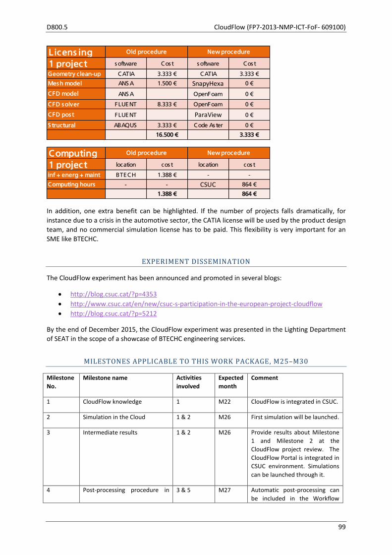
D800.5 CloudFlow (FP7-2013-NMP-ICT-FoF- 609100)
99
In addition, one extra benefit can be highlighted. If the number of projects falls dramatically, for
instance due to a crisis in the automotive sector, the CATIA license will be used by the product design
team, and no commercial simulation license has to be paid. This flexibility is very important for an
SME like BTECHC.
EXPERIMENT DISSEMINATION
The CloudFlow experiment has been announced and promoted in several blogs:
http://blog.csuc.cat/?p=4353
http://www.csuc.cat/en/new/csuc-s-participation-in-the-european-project-cloudflow
http://blog.csuc.cat/?p=5212
By the end of December 2015, the CloudFlow experiment was presented in the Lighting Department
of SEAT in the scope of a showcase of BTECHC engineering services.
MILESTONES APPLICABLE TO THIS WORK PACKAGE, M25–M30
Milestone
No.
Milestone name Activities
involved
Expected
month
Comment
1 CloudFlow knowledge 1 M22 CloudFlow is integrated in CSUC.
2 Simulation in the Cloud 1 & 2 M26 First simulation will be launched.
3 Intermediate results 1 & 2 M26 Provide results about Milestone
1 and Milestone 2 at the
CloudFlow project review. The
CloudFlow Portal is integrated in
CSUC environment. Simulations
can be launched through it.
4 Post-processing procedure in 3 & 5 M27 Automatic post-processing can
be included in the Workflow
Licens ing
1 project s oftware Cos t s oftware Cos t
Geometry clean-up CATIA 3.333 € CATIA 3.333 €
Mes h model ANS A 1.500 € SnapyHexa 0 €
CFD model ANS A OpenFoam 0 €
CFD s olver FLUENT 8.333 € OpenFoam 0 €
CFD pos t FLUENT ParaView 0 €
S tructural ABAQUS 3.333 € Code As ter 0 €
16.500 € 3.333 €
Old procedure New procedure
Computing
1 project location cos t location cos t
inf + energ + maint BTECH 1.388 € - -
Computing hours - - CSUC 864 €
1.388 € 864 €
New procedureOld procedure

CloudFlow (FP7-2013-NMP-ICT-FoF- 609100) D800.5
100
the Cloud Editor.
5 Pre-processing procedure in the
Cloud
4 & 5 M29 The Boundary & Mesh Editor
will be available.
6 Workflow launched with
CloudFlow Portal
1,2,3 &5 M30 Workflows will be launched
through the CloudFlow Portal.
7 Final Results 1,2,3 & 5 M31 A final experiment report will be
generated.
DEVIATION FROM PLANS, M25–M30
Most of the deviations from the initial planning are delays in the intended tasks due to the difficulties
found by CSUC in the CloudFlow installation on the HPC Centre. CSUC had to put up extra resources
to solve problems and some tasks were delayed. The complete workflow was planned to be ready by
the end of M30 (see milestone number 6 in previous point). It was also planned to devote time in
M31 to fix errors and improve the workflow.
Another remarkable deviation was in the stage of validation of OpenFOAM. The code did not account
properly the radiation through the semi-transparent materials. Extra effort was made in the task of
validation. The source code of OpenFOAM was modified in order to develop a radiation patch to be
used in semi-transparent materials.
After updating the planning, the complete workflow is expected to be ready by the end of the
experiment, in M31. If necessary, fixes and improvements will be made in M32 (out of the
experiment time).
DEVIATIONS FROM CRITICAL OBJECTIVES, M25–M30
There is no deviation from critical objectives.
REFLECTION ON FUTURE PLANS FROM D800.4
In the periodic reporting M20–M24, the future plans for M25–M30 were stated in the form of a task
list. These tasks focussed on the remote post-processing and on mapping the temperature gradient
obtained in the CFD OpenFOAM model to the structural Code Aster model. The degree of fulfilment
was stated previously in the section concerning the project activities.
FUTURE PLANS
Beyond the experiment time, the workflow can be improved if material properties and initial
conditions could be taken from a database instead of being input manually through a window. This
will make it possible to save time and avoid human mistakes in the input phase.

D800.5 CloudFlow (FP7-2013-NMP-ICT-FoF- 609100)
101
USED RESOURCES, M25–M30
WP127
BTECHC CSUC Sum
Used PMs M20-M24 4.50 5.25 9.75
Used PMs M25-M30 6.50 5.9 12.40
Available PMs M31 1.00 0.85 1.85
Planned M20-M31 12.00 12.00 24.00

CloudFlow (FP7-2013-NMP-ICT-FoF- 609100) D800.5
102
2.17 WP130 — 3rd wave of experiments
Start M22 End M39 Lead Fraunhofer
Participants SINTEF, Jotne, DFKI, UNott, CARSA, ARCTUR
OBJECTIVES (AS STATED IN GRANT AGREEMENT)
The aim of this work package is to handle all activities related to wave 3 experiments in a focused
and consistent manner. This covers:
defining selection criteria and the Open Call 2 text,
publishing Open Call 2 and promoting it in the target communities,
expert evaluator selection and briefing,
extracting the imposed requirements towards CloudFlow,
assessment of proposals, prioritization and selection,
internal review and support for consensus meetings,
accompanying/monitoring the execution of experiments,
accompanying/monitoring the assessment and validating of experiments.
TASK 130.1: CALL SPECIFICATION, PUBLICATION, AND EXPERIMENT SELECTION (AS STATED IN GRANT AGREEMENT)
This is the same as for Task 120.1, but for wave 3 experiments.
TASK 130.2: EXPERIMENT REQUIREMENTS ANALYSIS (AS STATED IN GRANT AGREEMENT)
This is the same as for Task 120.2, but for wave 3 experiments.
TASK 130.3: MONITORING OF THE EXECUTION OF EXPERIMENTS (AS STATED IN GRANT AGREEMENT)
This is the same as for Task 120.3, but for wave 3 experiments.
TASKS ADDRESSED IN WP130, M25–M30
The focus of the work in WP130 during M25–M30 has been on Task 130.1, publishing the Open Call,
evaluating the submitted proposals and selecting seven new experiments based on the evaluation
results.
The other tasks of this WP (Task 130.2 Experiment Requirements Analysis and Task 130.3 Monitoring
of the Execution of Experiments) will only be active in the second half of year 3, once the
experiments of the 3rd wave have been chosen and the new partners have joined the consortium.

D800.5 CloudFlow (FP7-2013-NMP-ICT-FoF- 609100)
103
SIGNIFICANT RESULTS
The main results of this work package during the reporting period are:
22 proposals have been submitted by the end of Month 27.
All proposals were evaluated in Month 28 and 29 by independent external experts and
internal experts, producing evaluation summary reports.
First versions of the Descriptions of Work for the selected experiments have been forwarded
to the Project Officer by the end of Month 31 for further processing by the EC.
MAIN ACTIVITIES IN THIS WORK PACKAGE, M25–M30
The main activity for this work package during M25–M30 was to acquire new experiments for the 3rd wave. A detailed report on this process and its outcome is provided as an annex to this report. The CloudFlow 2nd Open Call was published at the very end of M24 (30 June), with several accompanying documents (Guide for Applicants, Short Technical Description of the CloudFlow infrastructure, proposal template, webinar slides) that had been prepared by Fraunhofer and SINTEF in the previous period (M22–M23) with input from all partners. Additionally a list of frequently asked questions with experiences from the 1st Open Call was provided for the applicants. All this material is available from the project's web site. After the publication of the Call, extensive dissemination activities (see WP800) to solicit proposals were undertaken, including oral presentations at important events, a press release was distributed to news channels, distribution of specifically prepared flyers, webinars via I4MS, and direct invitations, also giving the possibility to proposers to contact the consortium directly via an info e-mail address. This resulted in frequent contacts with potential proposers, many more than originally expected. The electronic proposal submission and evaluation system which was set up by Fraunhofer for the 1st Open Call was reused in the 2nd Open Call. It was offered to the proposers to prepare their submissions and later by the evaluators for reviewing the assigned proposals. After the publication of the call, circa 70 potential external evaluators from the 1st Open Call were nominated by the consortium partners, of which circa 50 agreed to become evaluators. After analyzing the 22 submitted proposals and their specific application field we selected 15 evaluators (8 female and 7 male). Their fields of expertise and interests of the selected evaluators match against the proposal topics. The 2nd Open Call closed at the end of M28 (30 September). A total of 22 proposals were submitted. Each proposal was evaluated by three evaluators, two external and one internal evaluator from the system design group. Almost all external evaluators carried out three external evaluations and took part in the corresponding consensus meetings, and they were reimbursed for two days of work. After the individual evaluation phase, consensus meetings were held as teleconferences for each proposal (of circa one hour length), involving its three evaluators and monitored by a member of the core management team, leading to a successful conclusion for each proposal. The results were summarized in consensus reports that were made available to the proposers afterwards. Based on a letter with detailed comments from the core management and system design group, the teams of the seven selected proposals were asked to prepare an updated version of the proposal as a

CloudFlow (FP7-2013-NMP-ICT-FoF- 609100) D800.5
104
Description of Work. The finalized DoWs will be forwarded to the EC as soon as possible for further processing.
MILESTONES APPLICABLE TO THIS WORK PACKAGE, M25–M30
None
DEVIATION FROM PLANS
The seven selected experiments from the 2nd Open Call will start March 2016 instead of January
2016. This delay occurred because the SME validation took longer than expected. This, however, did
not have significant consequences for the experiment process and its results.
DEVIATIONS FROM CRITICAL OBJECTIVES
None
CORRECTIVE ACTIONS
None are necessary
REFLECTION ON FUTURE PLANS FROM D800.4
The successive steps related to the inclusion of new experiments planned in D800.4 have been carried out in the period M13–M18, starting from the promotion of the 1st Open Call to prioritizing and selecting the 7 new experiments at the end of M18. The final three steps listed under future plans in D800.2 remain — as planned — for the upcoming periods and are stated again below.
FUTURE PLANS
The plans for the next period cover the following activities:
formally enlarging the project consortium by the teams of the seven selected experiments
accompanying/monitoring the execution of experiments
accompanying/monitoring the assessment and validation of experiments
USED RESOURCES IN THIS WORK PACKAGE IN M25–M30
WP
13
0 Fr
aun
ho
f
er
SIN
TEF
JOTN
E
DFK
I
UN
ott
CA
RSA
NU
MEC
A
ITI
Mis
sle
r
AR
CTU
R
Ste
llba
Tota
l
Spent M25-M30 1.04 0.30 0.10 1.44
Spent Year 1
Spent Year 2 0.50 0.50 0.05 1.05
Spend M1-M30 0.50 1.54 0.30 0.05 0.10 2.49
Planned M1-M42 1.00 1.00 0.50 0.50 1.00 0.50 1.00 5.50
D800.5 CloudFlow (FP7-2013-NMP-ICT-FoF- 609100)
105
3 INFRASTRUCTURE WORK PACKAGES
The five work packages addressing the infrastructure are:
WP200: Data, addressed in Section 3.1,
WP300: Service, addressed in Section 3.1,
WP400: Workflows, addressed in Section 3.2,
WP500: Users, addressed in Section 3.4,
WP600: Business models, addressed in 3.5.
All these work packages have the same task structure:
Design (M3–M6, M20–M21, M31–M32),
Implementation (M7–M12),
Adaptation (M13–M21, M22–M30, M31–M39),
Verification (M10–M21, M22–M30, M31–M39).
Thus, in the current reporting period (M25–M30) the work mainly happened in tasks Adaptation and
Verification.

CloudFlow (FP7-2013-NMP-ICT-FoF- 609100) D800.5
106
3.1 WP200 – Data
Start M4 End M39 Lead JOTNE
Participants Fraunhofer, SINTEF, DFKI, NUMECA, Missler
Note that for completeness, the original objectives and task descriptions for WP200 from the
Description of Work (DoW) have been included at the end of this WP report.
The WP200 partners NUMECA and Missler completed their work in this work package at month M24.
TASKS ADDRESSED IN THIS WORK PACKAGE, M25–M30
The focus of the work in WP200 in M25–M30 has been on Adaptation (Task 200.3) and Verification
(Task 200.4) based on feedback from the final demonstration of wave 1 experiments and to support
the second wave of experiments.
SIGNIFICANT RESULTS
The main results of this work package are summarized as follows:
Completion of support for wave 1 experiments and their review demonstrations.
Analysis of requirements of the second wave experiments.
New PLM functions
o for uploading of complete branches of a product structure including documents;
o for subscribing to changes in the contents of the PLM database.
Improved semantic descriptions of services and workflows.
Daily backups of the semantic database to prevent unexpected data loss.
Extensions by SINTEF of their STEP reader (based on Jotne’s EXPRESS Data Manager) to
support a wider range of CAD models.
Implementation of new internal data structures within Fraunhofer IGD’s remote post-
processor for improved performance and flexibility.
Implementation of a VM-based caching mechanism for Fraunhofer IGD’s visualization
services for reducing the delay when generating 2D and 3D visualizations of commonly used
data sets.
MAIN ACTIVITIES IN THIS WORK PACKAGE, M25–M30
The activities in WP200 focused on adapting data management for the data flow along the workflow
chain and between the different services and applications as required for the wave 2 experiments.
TASK 200.3: ADAPTATION
Adaptations of the data solutions were triggered by developments in the other infrastructure work
packages, by user feedback from the wave 1 experiments and by requirements of the wave 2
experiments. The following activities were performed:
D800.5 CloudFlow (FP7-2013-NMP-ICT-FoF- 609100)
107
Jotne supported Numeca to make use of the storage of Key Performance Indicators (KPI) in
the PLM database. This feature gives the engineer a quick overview of the quality of massive
amounts of simulations without having to open files.
In response to wave 1 experiment feedback, Jotne extended the PLM functionality to include
the following in the PLM API; their inclusion in the end user GUIs is planned for the next
project period:
o Uploading of product structure branches including documents.
o Subscription to notifications of changes to a specifically identified data set in the PLM
database.
DFKI has improved the semantic service and workflow descriptions by storing their titles and
descriptions. These properties are now displayed during workflow execution.
DFKI improved the Workflow Editor by fixing usability issues and enhancing user friendliness,
such as value validation in URIs.
From now on, daily backups of the semantic database are made to prevent unexpected data
loss:
o Each backup is kept for fifteen days.
o In addition to daily backups, each 15th of the month, monthly backups are taken and
kept for one year.
SINTEF extended the range of STEP models accepted by their import functionality by
improving the approximation of trim curves in parameter space.
New internal data structures have been implemented for the server back-end of Fraunhofer
IGD’s remote post-processor. These improve the performance and reduce the memory
footprint of the application when dealing with large simulation data. The new data structures
also increase flexibility of the post-processor as they allow support of simulation results with
regular, structured and unstructured discretization, as well as multiple domains and arbitrary
result fields. Additionally this serves as preparation for simulation data provided by second
wave experiments (see WP120).
A caching mechanism has been implemented for all of Fraunhofer IGD’s visualization
services. When a visualization service is triggered by the Workflow Manager with a new data
set, the selected data set is cached locally on the virtual machine that hosts the service. For
files already present in the cache, the name, size and modification date of the cached data
will be compared with the information from the Cloud storage. When these parameters
match, the visualization will be computed using the cached data; data transfer between the
virtual machine and the cloud storage can then be skipped completely.
The loading functionality of Fraunhofer IGD’s visualization services has been improved to be
more robust regarding defective or incorrect CGNS files. Although most simulation tools are
able to export their simulation results in the CGNS format, the files are often not compliant
to the CGNS standard. The produced data sets contain custom hierarchies and internal
components that have to be treated individually.
JOTNE continued its cooperation with the ISO committee responsible for ISO 10303-209,
Multidisciplinary analysis and design. The main topic in this period was the publication of a technical
corrigendum for edition 2 of AP209 to correct some errors in the EXPRESS data model. Several of the
issues have been patched in underlying application modules of ISO 10303; the remaining ones are
scheduled for Change Request 12, which is due in the first half of 2016.

CloudFlow (FP7-2013-NMP-ICT-FoF- 609100) D800.5
108
TASK 200.4: VERIFICATION
The various software modules in support of data and semantics management were applied to the
experiment workflows and, thus, tested and verified using Stellba test data in case of wave 1
experiments and use case specific data in case of wave 2 experiments. Results were fed back to Task
200.3 for resolution.
Based on previously run performance tests on the different storage types, the implementation as
well as the overall network architecture have been adapted for both PLM and Swift storage. With
these modifications in place, a second set of storage performance tests has been executed. As
before, the up- and download performances of PLM and Swift storage were measured several times
with files of different sizes in order to measure the overall up- and download speed between the
Cloud storage and the virtual machines hosting the applications and services inside the CloudFlow
infrastructure. The results showed significant improvements especially for the PLM storage,
rendering it almost equally fast as Swift. PLM’s performance drawback discovered by the first tests
has been resolved.
MILESTONES APPLICABLE TO THIS WORK PACKAGE, M25–M30
None
DEVIATION FROM PLANS
None
DEVIATIONS FROM CRITICAL OBJECTIVES
None
CORRECTIVE ACTIONS
Partners experienced slow performance when communicating, for example, PLM data to and from
the CloudFlow Cloud. Limited network bandwidth was identified as one contributing factor. To have
an acceptable latency, the use of a high-speed Internet connection was attempted. This and other
implemented countermeasures, including changes in file handling on the server and REST type web-
services, sped up the communication of files to a good level.
PROGRESS BEYOND THE STATE OF THE ART
WP200 relates mainly to the state of the art Sections 1.2.2 “Semantic Technologies”, 1.2.3 “Semantic
Web Services” and 1.2.5 “Simulation Data Management in the Cloud”, in Part B of the Description of
Work.
Minor advances were achieved in progressing corrections in AP209e2 and in completing the semantic
descriptions of services.
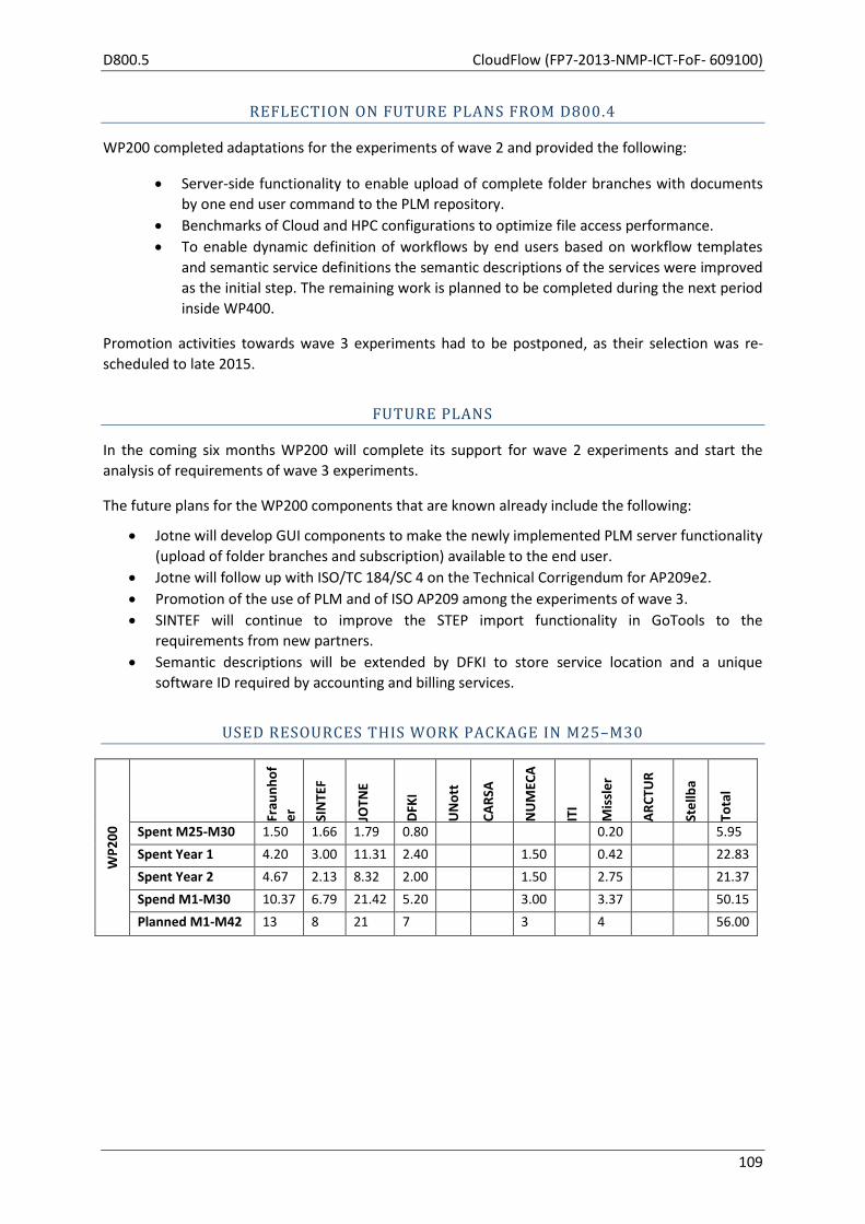
D800.5 CloudFlow (FP7-2013-NMP-ICT-FoF- 609100)
109
REFLECTION ON FUTURE PLANS FROM D800.4
WP200 completed adaptations for the experiments of wave 2 and provided the following:
Server-side functionality to enable upload of complete folder branches with documents
by one end user command to the PLM repository.
Benchmarks of Cloud and HPC configurations to optimize file access performance.
To enable dynamic definition of workflows by end users based on workflow templates
and semantic service definitions the semantic descriptions of the services were improved
as the initial step. The remaining work is planned to be completed during the next period
inside WP400.
Promotion activities towards wave 3 experiments had to be postponed, as their selection was re-
scheduled to late 2015.
FUTURE PLANS
In the coming six months WP200 will complete its support for wave 2 experiments and start the
analysis of requirements of wave 3 experiments.
The future plans for the WP200 components that are known already include the following:
Jotne will develop GUI components to make the newly implemented PLM server functionality
(upload of folder branches and subscription) available to the end user.
Jotne will follow up with ISO/TC 184/SC 4 on the Technical Corrigendum for AP209e2.
Promotion of the use of PLM and of ISO AP209 among the experiments of wave 3.
SINTEF will continue to improve the STEP import functionality in GoTools to the
requirements from new partners.
Semantic descriptions will be extended by DFKI to store service location and a unique
software ID required by accounting and billing services.
USED RESOURCES THIS WORK PACKAGE IN M25–M30
WP
20
0 Fr
aun
ho
f
er
SIN
TEF
JOTN
E
DFK
I
UN
ott
CA
RSA
NU
MEC
A
ITI
Mis
sle
r
AR
CTU
R
Ste
llba
Tota
l
Spent M25-M30 1.50 1.66 1.79 0.80 0.20 5.95
Spent Year 1 4.20 3.00 11.31 2.40 1.50 0.42 22.83
Spent Year 2 4.67 2.13 8.32 2.00 1.50 2.75 21.37
Spend M1-M30 10.37 6.79 21.42 5.20 3.00 3.37 50.15
Planned M1-M42 13 8 21 7 3 4 56.00
CloudFlow (FP7-2013-NMP-ICT-FoF- 609100) D800.5
110
OBJECTIVES (AS STATED IN GRANT AGREEMENT)
Data within engineering and manufacturing processes are big, heterogeneous and fragmented. Work
package 200 is designed to cope with the challenges on data integration and interoperability. The
experiments’ requirements on data are driving the activities in WP200. The following two pillars form
the technological basis to cope with these requirements:
a) to use the data model of STEP AP209 where possible and reasonable for data exchange and
data integration,
b) to bridge islands of heterogeneous data with semantic models and knowledge
representation technology.
WP200 will design, implement, adapt and verify (in cycles — according to the waves of experiments)
the data management infrastructure in CloudFlow. This will ensure a data flow along the workflow
chain and between the different service applications as required by the experiments. A CloudFlow
data dictionary will manage the aspects of the system including user access, engineering contents,
services, workflow, and business model. The goal of openness and standards compliance will guide
the implementation of also this system’s dictionary in a database located in the Cloud.
A semantic layer will bridge the islands of heterogeneous data by dedicated small-scale ontologies to
guarantee agility and flexibility towards new requirements and newly integrated data sources and
sinks. The special purpose of the semantic layer is the communication between the user and the
services, that is, query formulation guidance by means of ontologies and faceted search, and
semantic search for data items by attributes and by their relationships to other items utilizing
automated reasoning. These ontologies will finally link up smoothly to support data
integration/interoperability chains.
TASK 200.1: DESIGN (AS STATED IN GRANT AGREEMENT)
Duration M04–M06, M20–M21, M31–M32 Lead JOTNE
Participants Fraunhofer, SINTEF, DFKI, NUMECA, Missler
This task addresses the design of the CloudFlow infrastructure based on experiment requirements
and existing technologies that include the following:
initial Cloud-based data management infrastructure,
applications with interoperability requirements,
STEP AP209 converters,
metadata, especially for long-term archival and retention purposes, as well as
semantic data management layer and knowledge representation technologies.
TASK 200.2: IMPLEMENTATION (AS STATED IN GRANT AGREEMENT)
Duration M07–M12 Lead SINTEF
Participants Fraunhofer, JOTNE, DFKI, NUMECA, Missler
D800.5 CloudFlow (FP7-2013-NMP-ICT-FoF- 609100)
111
This task addresses the implementation of the CloudFlow infrastructure based on existing technologies.
implementing the initial data management infrastructure,
including data description and data mapping tools based on interface and archival descriptions and dedicated ‘small-scale’ ontologies.
TASK 200.3: ADAPTATION (AS STATED IN GRANT AGREEMENT)
Start M25 End M39 Lead DFKI
Participants Fraunhofer, SINTEF, Jotne, NUMECA, Missler
This task addresses the adaptation the infrastructure, including feedback from the running wave of
experiments:
Adapting and extending the infrastructure.
Including results from the running wave of experiments.
Taking into account requirements of experiments to be carried out.
TASK 200.4: VERIFICATION (AS STATED IN GRANT AGREEMENT)
Duration M11–M21, M23–M30, M32–M39 Lead Jotne
Participants Fraunhofer, SINTEF, DFKI, NUMECA, Missler
This task verifies the results against the requirements/specifications from a technical point of view. It
runs at the end of the first implementation phase and mutually in parallel to the adaptation task
(including software testing before releasing for an experiment). Verification results are forwarded to
WP100 for further integration with other aspects of experiments evaluation and to assess and
validate them in a bigger context and scope.
CloudFlow (FP7-2013-NMP-ICT-FoF- 609100) D800.5
112
3.2 WP300 — Services
Start M04 End M39 Lead SINTEF
Participants Fraunhofer, DFKI, NUMECA, ITI, Missler, ARCTUR
Note that for completeness, the original objectives and task descriptions for WP300 from the
Description of Work (DoW) have been included at the end of this WP report.
TASKS ADDRESSED IN THIS WORK PACKAGE, M25–M30
The focus of the work in WP300 in M25–M30 has been on Adaptation (Task 300.3) and Verification
(Task 300.4).
SIGNIFICANT RESULTS
The main results of this work package are summarized as follows:
Services facilitating easy use of HPC resources in a workflow are implemented and tested.
The software infrastructure is updated to facilitate the two new HPC/Cloud providers
included in the second wave of experiments. The infrastructure was designed to support
such providers, and the additional software is designed and the implementation is underway.
The Generic Storage Services are partially extended to support HPC storage type, as required
by a second wave experiment. When this extension is complete, HPC providers can easily
integrate the users’ home folders into the CloudFlow infrastructure.
HPC services are successfully integrated and validated in several experiments.
DFKI has solved a CORS (Cross-origin resource sharing) issue that was introduced after
allowing components to be distributed in different virtual, physical locations, or domains.
Fraunhofer IGD’s remote post-processing service has been migrated to a new machine
equipped with a high-performance GPU to improve performance and reduce response times
when processing commands from the HTML thin client. At the same time, the service has
been adapted to use more memory-efficient internal data structures. Additionally, multiple
bugs were fixed on the server back-end.
A tool has been developed for measuring available network bandwidth and latency between
the end user’s local machine and different points inside the CloudFlow infrastructure. This
helps estimating what performance the end user can expect when using CloudFlow services
from his/her current location or network.
The GridWorker Generic Simulation Service by Fraunhofer EAS has been extended. The new
version supports an improved monitoring of running simulation tasks, checkpointing for long-
lasting simulations as well as notifications.
A first version of an Editor service was developed by Fraunhofer EAS to enable users to easily
edit small text files located in the Cloud storage without downloading and uploading to/from
the local machine, e.g. configuration files.

D800.5 CloudFlow (FP7-2013-NMP-ICT-FoF- 609100)
113
MAIN ACTIVITIES IN WP300, M25–M30
The main activities in WP300 between M25 and M30 are focused on facilitating second wave
experiments, supporting new HPC/Cloud services and preparing the software infrastructure required
for commercial use.
TASK 300.3: ADAPTATION
Generic and experiment specific services have been stabilized and adapted for better user
experience. More detailed descriptions are presented in the WPs for each experiment. The following
activities were performed:
Services required for accounting and billing are designed, and they will be implemented by
Fraunhofer EAS, DFKI and Arctur, with support from SINTEF.
The semantic description of services is extended to facilitate accounting and billing.
In the second wave of experiments there are two new HPC/Cloud providers. They provide
two new ways of using the CloudFlow infrastructure:
o Multi-cloud: CloudFlow services are implemented in a separate cloud environment
from the Workflow Manager. Our solution to this is that the user logs in to both
environments from the CloudFlow Portal, and we implement services to simplify the
handling of two authentication systems. The solution is designed and partially
implemented by DFKI and SINTEF.
o HPC provider: The whole CloudFlow software infrastructure is installed in a cloud
environment associated with a HPC provider. This is the first time the infrastructure
as a whole is installed outside Arctur. All core components are installed and tested,
and we are on schedule to finalize the adaptation for the second wave experiment.
This also demanded that the Generic Storage Services are extended by SINTEF to
support HPC file systems, which also is developed according to the plan.
New monitoring features have been implemented for the GridWorker Generic Simulation
Service. The monitoring status is shown within the status page of a service provided by the
Workflow Manager while a service is running. Now a user gets information on the number of
running/completed/failed/aborted tasks which is helpful for parametric studies performing a
large number of single simulation tasks. Based on the observation of this overall status of a
running service a user can decide to abort a workflow if the monitoring status detects failed
tasks. In this way, the monitoring service can help to save computing resources as well as
time and money.

CloudFlow (FP7-2013-NMP-ICT-FoF- 609100) D800.5
114
Figure 11. The service status contains information on the total number of tasks and jobs and their individual
current state. A user can observe the progress of a running session.
For many long-lasting simulation tasks it is necessary to get intermediate results. Based on
this information a user can check the progress of single tasks. For the GridWorker Generic
Simulation Service a new feature called checkpointing has been implemented. A user can
configure a time interval for periodic checkpointing or initiate a checkpoint on-demand using
a service notification (see below). Furthermore, the storage location of the intermediate
results can be configured. Currently the SWIFT storage is supported as target location. The
new checkpointing feature improves significantly the usability of the CloudFlow workflows. It
can be used on the Cloud as well as on HPC back-ends.
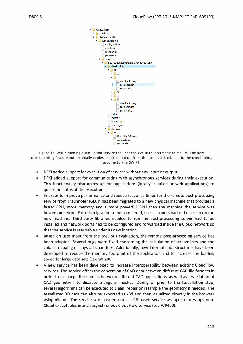
D800.5 CloudFlow (FP7-2013-NMP-ICT-FoF- 609100)
115
Figure 12. While running a simulation service the user can evaluate intermediate results. The new
checkpointing feature automatically copies checkpoint data from the compute back -end to the checkpoints
subdirectory in SWIFT.
DFKI added support for execution of services without any input or output.
DFKI added support for communicating with asynchronous services during their execution.
This functionality also opens up for applications (locally installed or web applications) to
query for status of the execution.
In order to improve performance and reduce response times for the remote post-processing
service from Fraunhofer IGD, it has been migrated to a new physical machine that provides a
faster CPU, more memory and a more powerful GPU than the machine the service was
hosted on before. For this migration to be completed, user accounts had to be set up on the
new machine. Third-party libraries needed to run the post-processing server had to be
installed and network ports had to be configured and forwarded inside the Cloud network so
that the service is reachable under its new location.
Based on user input from the previous evaluation, the remote post-processing service has
been adapted. Several bugs were fixed concerning the calculation of streamlines and the
colour mapping of physical quantities. Additionally, new internal data structures have been
developed to reduce the memory footprint of the application and to increase the loading
speed for large data sets (see WP200).
A new service has been developed to increase interoperability between existing CloudFlow
services. The service offers the conversion of CAD data between different CAD file formats in
order to exchange the models between different CAD applications, as well as tessellation of
CAD geometry into discrete triangular meshes. During or prior to the tessellation step,
several algorithms can be executed to clean, repair or resample the geometry if needed. The
tessellated 3D data can also be exported as x3d and then visualized directly in the browser
using x3dom. The service was created using a C#-based service wrapper that wraps non-
Cloud executables into an asynchronous CloudFlow service (see WP400).
CloudFlow (FP7-2013-NMP-ICT-FoF- 609100) D800.5
116
TASK 300.4: VERIFICATION
During M25–M30 the verification of the generic services has been through new users, both
developers, and end users.
To evaluate Cloud performance and connectivity, a tool has been developed that measures the
network bandwidth and the latency between the end user’s client machine and the CloudFlow
infrastructure. These characteristic numbers help estimating the user experience a user can expect
when using CloudFlow services and workflows from his/her current location or network (e.g. office
computer, laptop, mobile device). This is especially important for bandwidth-heavy applications like
remote visualization or remote post-processing services.
MILESTONES APPLICABLE TO THIS WORK PACKAGE, M25–M30
None
DEVIATION FROM PLANS
We use an agile approach to the design-adapt-verify loop. Therefore we do not strictly follow the
schedule for Task 300.1 Design. Frequent teleconferences are used to ensure that the infrastructure
development plan matches the experiment development requirements.
DEVIATIONS FROM CRITICAL OBJECTIVES
None
CORRECTIVE ACTIONS
None
PROGRESS BEYOND THE STATE OF THE ART
In this work package we develop many of the necessary building blocks for successful workflow
deployment and execution. The use of semantic descriptions of available services is an important
aspect of the CloudFlow project. Each service and its input and output parameters are given semantic
descriptions. The developed ontologies have been successfully tested during the definition of
workflows for the first wave of experiments. With the new Workflow Editor functionality the
semantic definitions can be created by the service developer directly, which will be important for the
second wave of experiments.
At the current development status of the project and especially of this work package, we can point
out the following new progress beyond the state of the art, referring to Section 1.2 of the DoW:
Designed solution to allow services to be executed in a multi-cloud setting, agnostic to the
underlying cloud technologies.
Support for HPC infrastructures to be accessed as a Cloud resource.

D800.5 CloudFlow (FP7-2013-NMP-ICT-FoF- 609100)
117
REFLECTION ON FUTURE PLANS FROM D800.4
The development has followed the path sketched in D800.4, and progress has been made on all
topics apart from restricting the access from services. This will be targeted in the next period, where
we extend the use of authentication. Topics that were addressed include:
Designing and starting the implementation of services to support HPC/Cloud providers
introduced by second wave partners. The implementation will be completed shortly as part
of the second wave of experiments.
Designing and starting the implementation of services to support storage solutions from new
partners. The implementation will be completed shortly as part of the second wave of
experiments.
FUTURE PLANS
Complete services to support HPC/Cloud providers introduced by second wave partners.
Extend the use of authentication to improve security.
Improve the secure storage and transfer of credential information (passwords, certificates,
tokens).
Minimize communication overhead and memory footprint for performance-critical services
(e.g. GridWorker Generic Simulation Service).
Implement services for accounting and billing based on the business models defined in
WP800.
Integration of accounting and billing services into Workflow Manager.
Editor service will be adapted/extended to work with text files stored in PLM.
USED RESOURCES IN THIS WORK PACKAGE IN M25–M30
WP
30
0 Fr
aun
ho
f
er
SIN
TEF
JOTN
E
DFK
I
UN
ott
CA
RSA
NU
MEC
A
ITI
Mis
sle
r
AR
CTU
R
Ste
llba
Tota
l
Spent M25-M30 2.75 2.15 0.50 0.40 2.58 1.26 9.64
Spent Year 1 9.05 7.00 4.10 7.00 1.50 1.31 1.46 31.42
Spent Year 2 6.25 4.00 3.20 2.00 1.15 3.12 2.37 22.09
Spend M1-M30 18.05 13.15 7.80 9.00 3.05 7.01 5.09 63.15
Planned M1-M42 21 17 9 9 4 8 2 70.00
CloudFlow (FP7-2013-NMP-ICT-FoF- 609100) D800.5
118
OBJECTIVES (AS STATED IN GRANT AGREEMENT)
WP300 Services plays a similar role for services as WP200 plays for data. Here the focus is on service
interoperability and transparent service execution in the Cloud. Services may have to be adapted to
Cloud environments and their interfaces have to be abstracted and described in a standardized
manner. WP300 runs in three cycles of designing solutions that answer the requirements imposed by
the waves of experiments, implement, adapt and verify them.
Since the standard interface method (e.g. WSDL) is of mere syntactical nature, reasoning about the
effects and pre-conditions of simulation, pre- and post-processing services is not possible. Semantic
descriptions about the features of services, effects, preconditions and parameters allow for a
dynamic orchestration of simulation processes. Dynamic orchestration describes the logical inference
of a concrete workflow at runtime. The concept of dynamic orchestration builds upon the application
of the paradigm of service-oriented architectures. It allows for an automated discovery, selection and
orchestration of appropriate simulation services based on the description of a service’s capabilities
and interface. The semantic description of services allows representing the meaning of these
descriptions in a machine-understandable manner. By modelling the correlation between service
descriptions in domain-specific ontologies, which specifies e.g. the available services, a logical
reasoning over the explicitly modelled knowledge can be performed. In this way, the end user’s
simulation requests can automatically be processed and answered.
The aim of this work package is to realize an on-demand execution and orchestration of simulation
services where the services are automatically executed based on a semantic description of the
service capabilities, its effects, preconditions and parameters. The semantic core model will include
the following elements:
a Cloud function ontology, which represents a structure of services that can be performed by
the Cloud configuration,
a service ontology, which contains a collection of service categories (types of simulation: pre-
processing service, simulation and analyses service, post-processing service) and
a parameter ontology, which provides means for the semantic annotation of input and
output data of a simulation service.
TASK 300.1: DESIGN (AS STATED IN GRANT AGREEMENT)
Duration M04–M06, M20–M21, M31–M32 Lead SINTEF
Participants Fraunhofer, DFKI, NUMECA, ITI, Missler, ARCTUR
This task addresses the design of the CloudFlow service infrastructure based on the identified
requirements and specifications of the corresponding wave. Main design criteria have been:
where possible, base the service infrastructure on existing standards and technologies,
simulation software from competing vendors must be appropriate for integration into a
common workflow,
extended by semantic service description layer and knowledge representation technologies
such as OWL-S, OWL, and SAWSD.
D800.5 CloudFlow (FP7-2013-NMP-ICT-FoF- 609100)
119
TASK 300.2: IMPLEMENTATION (AS STATED IN GRANT AGREEMENT)
Duration M07–M12 Lead Missler
Participants Fraunhofer, SINTEF, DFKI, NUMECA, ITI, ARCTUR
In this task we implement a first version of Cloud-based services to be able to run the experiments of
the first wave. These services will cover:
Implementation of individual simulation services in the Cloud.
Implementation of the necessary additions and modifications to GridWorker and Tinia to facilitate the service infrastructure.
‘Porting’ existing software provided by our SME partners into the Cloud.
Focus is on services (CAD/CAM and CAE services) and data about services (service description / metadata).
TASK 300.3: ADAPTATION (AS STATED IN GRANT AGREEMENT)
Duration M25–M21, M22-30, M31-39 Lead NUMECA
Participants Fraunhofer, SINTEF, DFKI, ITI, Missler, ARCTUR
The adaptation will take the preliminary results of the corresponding running wave of experiments
into account. This task supports the extension and fine-tuning of the service infrastructure to the
needs of the selected experiments and taking into account feedback from the running wave. Another
important aspect of services for the more complex experiments is interactivity. It is envisaged to not
just work on services that run as batch processes but also on interactive services that react on user
input, e.g. in the modelling and processing stage.
TASK 300.4: VERIFICATION (AS STATED IN GRANT AGREEMENT)
Duration M11–M21, M23–M30, M32-39 Lead SINTEF
Participants Fraunhofer, DFKI, ITI, NUMECA, Missler, ARCTUR
This task is performed in three cycles in each wave of experiments, verifying the individual
requirements of the experiments towards services, and forwarding the results of the service-oriented
verification to WP100 for further integration with other aspects of experiments verification and to
further assess and validate them in a bigger context and scope.
CloudFlow (FP7-2013-NMP-ICT-FoF- 609100) D800.5
120
3.3 WP400 — Workflows
Start M04 End M39 Lead Fraunhofer
Participants SINTEF, DFKI, ITI
Note that for completeness, the original objectives and task descriptions for WP400 from the
Description of Work (DoW) have been included at the end of this WP report.
TASKS ADDRESSED IN THIS WORK PACKAGE, M25–M30
The focus of the work in WP400 in M25–M30 has been on Adaptation (Task 400.3) and Verification
(Task 400.4).
SIGNIFICANT RESULTS
The main results of this work package are summarized as follows:
Development of a wrapper for applications with clearly defined input and output parameters
to create asynchronous services, and integrate these into workflows within the CloudFlow
infrastructure.
Enhancement of all workflows containing Fraunhofer IGD’s visualization and post-processing
services to be also used in the 2nd wave experiments.
First steps on coupling Fraunhofer IGD’s interactive deformation simulation service and ITI’s
system simulation for dynamic bidirectional exchange of data during an active simulation.
Workflows are now able to display HTML as output after completion. Furthermore, the
Workflow Manager can abort workflows now.
The Workflow Manager passes extra parameters to workflows and services, e.g. to publish its
own URI for call-backs.
The GridWorker Generic Simulation Service was adapted to be compatible with the new
version Kilo of the OpenStack middleware at Arctur.
Now the GridWorker Generic Simulation Service supports the aborting as well as notification
handling by the Workflow Manager. Furthermore, GridWorker monitors the status of all
simulation tasks and reports back the status to the Workflow Manager with an informative
HTML page periodically.
Adaptation of the Cloud Management Service to support the new version of OpenStack
middleware at Arctur.
A design for workflows spanning multiple cloud solutions is in place. This will also enable
services to be executed in another Cloud solution than the Workflow Manager is installed in.
For experiment-specific workflow aspects please see the reports on WP111–WP116 and WP121–
WP127.
MAIN ACTIVITIES IN THIS WORK PACKAGE, M25–M30
TASK 400.1: DESIGN
No activities in this reporting period.
D800.5 CloudFlow (FP7-2013-NMP-ICT-FoF- 609100)
121
TASK 400.2: IMPLEMENTATION
No activities in this reporting period.
TASK 400.3: ADAPTATION
The workflows involving Fraunhofer IGD’s visualization and post-processing services have been
adapted to also support data sets provided by the 2nd wave of experiments. New parameters have
been introduced to improve the flexibility of these services and to allow their re-use in new
workflows needed for wave 2.
First steps have been taken on coupling Fraunhofer IGD’s interactive deformation simulation service
with ITI’s system simulation. During a simulation run, the system simulation service is planned to
communicate with the interactive deformation simulation service and send computed displacements
of specified parts within the simulation model. The deformation simulation service will then compute
the stress and internal forces induced by this displacement and send the results back to the system
simulation service. To improve this process, the internal communication back-end of the deformation
simulation service has been refactored and improved to reduce CPU load and provide faster
processing of incoming and outgoing messages.
A new wrapper has been developed to quickly create asynchronous services from non-Cloud
applications that offer a clearly defined set of input and output parameters. In order to set the input
parameters on a service level, they will be mapped to parameters of the service call that can either
be defined directly by the Workflow Manager or manually by the user through a dynamically
generated HTML GUI. It was tested with an application that can convert CAD files between several
CAD formats or tessellate them to generate discrete 3D geometry data. This service can either be
integrated into workflows as a converter in order to connect services with incompatible in- and
output formats, or appended to workflows dealing with CAD data in order to visualize the 3D
geometry as the final step.
With feedback from 2nd wave partners, Workflow Manager has been improved as follows:
Workflow results can now be customized to display a custom HTML after they are complete.
This HTML may also contain images and interactive elements such as forms.
Workflows can be aborted by user interaction manually.
Initial work on (semi-)automatic orchestration of workflows has been done by enhancing semantic
descriptions of services and workflows to store their input and outputs.
As a new version of the OpenStack Cloud middleware was installed at Arctur, the Cloud Management
Service was adapted to support this new version. Some minor API changes where necessary.
The GridWorker Generic Simulation Service was adapted to be compatible with OpenStack Kilo. A
generic workflow has been created for the evaluation of the new Cloud infrastructure at ARCTUR.
The main advantages of OpenStack Kilo are the improved and stabilized functionality for the
maintenance of VMs as well as the improved startup/shutdown performance of dynamically
allocated compute resources.
Besides the Workflow Manager, the GridWorker Generic Simulation Service now also supports the
abortion of the service as well as the notification handling.
SINTEF and DFKI designed a solution for workflows spanning multiple cloud solutions. Usually, only
one cloud solution will be used for each workflow to avoid unnecessary transportation of data.

CloudFlow (FP7-2013-NMP-ICT-FoF- 609100) D800.5
122
All core partners have assisted second wave experiments to design and implement the experiment
and deploy specific workflows.
TASK 400.4: VERIFICATION
The workflow set up was continuously tested against the experiments’ and overall objectives. The
identified issues have directly affected the content and work of the second adaptation phase.
Based on feedback from users and own tests, Workflow Manager as well as GridWorker were
adapted and improved. The compatibility with the different HPC and Cloud environments used and
provided in CloudFlow was verified and ensured.
MILESTONES APPLICABLE TO THIS WORK PACKAGE, M25–M30
None
DEVIATION FROM PLANS
None
DEVIATIONS FROM CRITICAL OBJECTIVES
None
CORRECTIVE ACTIONS
None necessary
PROGRESS BEYOND THE STATE OF THE ART
At the current development status of the project and especially of this work package, we can point
out the following progress beyond the state of the art referring to Sections 1.2.1, 1.2.3, 1.2.4, and
1.2.8 of the DoW:
Having a common interface for all services as well as a common semantic description, the
possibility of a dynamic/semi-automatic workflow orchestration is given.
According to the size of parameter sets of simulation tasks, the Cloud resources (number of
virtual machines, cores, RAM, etc.) can be requested on-demand using the Cloud
Management Service with a common interface for the different Cloud middleware
used/provided in CloudFlow. This enables a high degree of flexibility for engineers as end
users. Cost vs. runtime of such a task can be optimized according to requirements.
With its open interface, GridWorker enables the encapsulation/integration of a large number
of simulation and engineering tools and can in a simple manner be extended to further
needs.
Switching to secured web (HTTPS) as well as web socket (WSS) protocols improves the
secured data transfers between workflow components as well as to the end user
significantly.
Extending the supported Cloud middleware to OpenStack avoids Cloud provider lock-in.

D800.5 CloudFlow (FP7-2013-NMP-ICT-FoF- 609100)
123
REFLECTION ON FUTURE PLANS FROM D800.4
In this reporting period many important points of the future plan as listed in D800.4 for this WP have
been handled. The Workflow Editor and Manager were permanently adapted and improved to meet
the needs of the 2nd wave experiments. This is mainly based on the tight cooperation between the
system design group and 2nd wave partners. Initial work on (semi-)automatic orchestration of
workflows has been done by enhancing semantic descriptions of services and workflows to store
their input and outputs. Monitoring of service availabilities as well as the service and infrastructure
status is available in the form of a web page with a tabular view of all status information at Arctur’s
site. The new monitoring and checkpointing features improve the observability of CloudFlow
workflows. They will help to minimize wasted compute resources by cancelling the workflow after
errors have been monitored. Efficiency, robustness and fault tolerance of all workflow tools were
improved to enhance the stability and user friendliness of the entire infrastructure.
FUTURE PLANS
In the upcoming third design and adaptation phases, the WP has to deal with the following aspects:
Intensive testing and adapting of all workflow tools according the new set of experiments (3rd
wave).
Optimization of data exchange rates between the services of a workflow.
Further improving the efficiency, robustness and fault tolerance.
Completion of semi-automatic orchestration of workflows to suggest compatible services
during the creation of a workflow.
USED RESOURCES IN THIS WORK PACKAGE IN M25–M30
WP
40
0 Fr
aun
ho
f
er
SIN
TEF
JOTN
E
DFK
I
UN
ott
CA
RSA
NU
MEC
A
ITI
Mis
sle
r
AR
CTU
R
Ste
llba
Tota
l Spent M25-M30 2.75 0.90 0.30 0.60 4.55
Spent Year 1 6.95 7.52 4.70 2.10 21.27
Spent Year 2 10.13 7.13 2.23 3.08 22.57
Spend M1-M30 19.83 15.55 7.23 5.78 48.39
Planned M1-M42 24 21 9 8 62.00

CloudFlow (FP7-2013-NMP-ICT-FoF- 609100) D800.5
124
OBJECTIVES (AS STATED IN GRANT AGREEMENT)
The aim of this work package is to enable the execution of chains of services or services-in-a-loop in a
synchronized and orchestrated manner. To this end, WP400 will develop a workflow infrastructure
focusing on orchestration of compute services (as developed in WP300) in the Cloud. This will enable
scenarios of co-simulation of mechatronic and multi-physics systems over a set of distributed but
interoperable services.
Furthermore, CloudFlow workflows will allow for defining advanced design flows including simulation
as well as pre-processing of model descriptions and post-processing of simulation results. Using
appropriate front-ends (see WP500) the engineer can describe, orchestrate, instantiate, control and
monitor workflows to solve complex analysis tasks in system design. Although the main focus of the
work package is on simulation-based tool chains, other complex engineering workflows such as the
design and validation of a product and its tools (manufacturing) also require chained services or even
co-execution of engineering services (multi-physics).
The work is based on interface specifications for simulation services on a syntactic and semantic
level. Interface technologies such as FMI (functional mock-up interface), HLA (high-level architecture)
and DIS (distributed interactive simulation) will be evaluated. The most promising approach, FMI, has
been developed in the EU-funded project MODELISAR and is supported by more than 30 tool vendors
including the CloudFlow partner ITI. Furthermore, the work package will evaluate and select suitable
workflow formalisms (Petri nets, UML activity diagrams, BPMN, DAG, finite-state machines),
workflow languages (BPMS, BPEL/BPEL4WS, OWL-S) and workflow engines and editors (GWES,
JGrafchart) for implementing CloudFlow workflow solutions. The main goal of the implementation
and adaption task is to improve the flexibility of CloudFlow services by workflows.
Concerning the orchestration of workflows, the aim of this work package is to extend existing
orchestration solutions with the possibility to support the choice of services, to make the special pre-
requisites (such as modelling paradigms and result abstractions) explicit and to be able to monitor
the progress of an executed process instance. This requires two main sub-objectives:
To semantically model the meaning of data, the capabilities of simulation, computation and
pre- or post-processing services and the meaning of results. Basic technologies are OWL to
represent the services properties and their interrelations in ontologies, RDF and SPARQL to
deal with semantic searches on mass data, BPEL, BPNM and OWL-S to represent the
orchestration and AP209 to represent the product data contents of engineering analyses.
Strong parallels can be drawn to the semantically supported dynamic orchestration of
manufacturing processes where the capabilities of the different equipment is modelled in an
extensible set of ontologies and the orchestration of services is realized on a semantic
capability search and semantic match making.
To select appropriate service profiles that are able to do eventing to set up a status
communication between the Cloud services, the orchestrator and the user interface. The
extension of web services with the possibility of eventing has been realized in the domain of
factory automation. Technologies are e.g. DPWS. The orchestration of such services and the
reaction to events can be realized using orchestration systems from factory and process
automation such as JGrafchart. Those approaches will be transferred to the chaining of Cloud
simulation services.
The goal of these activities is to improve the efficiency, robustness and fault tolerance of CloudFlow
services by workflows. Usually, in highly distributed infrastructures the number of failures is
D800.5 CloudFlow (FP7-2013-NMP-ICT-FoF- 609100)
125
becoming more crucial. There are some intelligent algorithms and workflows needed to detect and
handle exceptions and errors. WP400 will address these challenges and will implement and evaluate
corresponding solutions.
TASK 400.1: DESIGN (AS STATED IN GRANT AGREEMENT)
Duration M04–M06, M20–M21, M31–M32 Lead Fraunhofer
Participants SINTEF, DFKI, ITI
This task designs the methodology and concepts to be used in implementing service orchestration in
the Cloud. The design will be based on existing technology, e.g. FMI (functional mock-up interface),
HLA (high-level architecture), DIS (distributed interactive simulation) extended by a semantic
orchestration language.
The design phase extends the existing graphical editors for the orchestration (such as JGrafchart,
BPEL Designer, etc.) for the application in the area of simulation services. The semantic description is
set up based on an evaluation of the engineering processes and tools used in the domain of CAx
today. Based on this, concepts are developed, including how the monitoring process can be realized
based on the possibility of eventing, which is available in some web service specifications such as
DPWS.
TASK 400.2: IMPLEMENTATION (AS STATED IN GRANT AGREEMENT)
Start M07 End M12 Lead ITI
Participants Fraunhofer, SINTEF, DFKI
In this task we implement a first version of Cloud-based workflows to be able to run the experiments
of the 1st wave. The implementation will address the following aspects:
data needs
interfaces
network, bandwidth, communication overhead and latencies
data exchange rates, especially for co-simulation scenarios
data exchange mechanisms (push, pull)
Focus is on workflows to enable system simulations consisting of several components, e.g. software,
electrics/electronics, mechanics. Furthermore, workflows will be supported that combine simulation
with certain post-processing tools (e.g. for statistical analysis).
TASK 400.3: ADAPTATION (AS STATED IN GRANT AGREEMENT)
Duration M25–M21, M22–M30, M31–M39 Lead SINTEF
Participants Fraunhofer, DFKI, ITI
The adaptation will take the preliminary results of the running wave of experiments into account and
the requirements of the selected experiments. Important aspects of workflows for the more complex
experiments are frequent communication of intermediate results (data), e.g. in the case of co-
simulation, still being able to cope with interactive events, and fault tolerance and overall efficiency.
CloudFlow (FP7-2013-NMP-ICT-FoF- 609100) D800.5
126
This task will adapt the workflow infrastructure over the course of the project, gradually addressing
the aspects mentioned in Task 400.2.
TASK 400.4: VERIFICATION (AS STATED IN GRANT AGREEMENT)
Duration M11–M21, M23–M30, M32–M39 Lead Fraunhofer
Participants SINTEF, DFKI, ITI
This task verifies the results against the requirements/specifications from a technical point of view. It
runs at the end of the first implementation phase and mutually in parallel to the adaptation task
(including software testing before releasing for an experiment). Verification results are forwarded to
WP100 for further integration with other aspects of experiments evaluation and to assess and
validate them in a bigger context and scope.

D800.5 CloudFlow (FP7-2013-NMP-ICT-FoF- 609100)
127
3.4 WP500 — Users
Start M04 End M39 Lead DFKI
Participants Fraunhofer, SINTEF, UNott, NUMECA, ITI, Missler
Note that for completeness, the original objectives and task descriptions for WP500 from the
Description of Work (DoW) have been included at the end of this WP report.
TASKS ADDRESSED IN THIS WORK PACKAGE, M25–M30
The focus of the work in WP500 in M25–M30 has been on Adaptation (Task 500.3) and Verification
(Task 500.4), based on feedback from first wave partners and to support second wave partners.
SIGNIFICANT RESULTS
The main results of this work package are summarized in the following list:
Workflow Editor has been improved by DFKI with the feedback from first wave experiments.
DFKI and SINTEF improved the CloudFlow Portal related to user friendliness, after user
evaluation of first wave partners.
Configurable extra parameters for services are introduced by DFKI.
A new prototypical user interface has been designed for Fraunhofer IGD’s remote post-
processing service aiming at a restructured placement of UI-elements. The restructuring aslo
enabled a more efficient processing of user inputs.
Fraunhofer IGD has adapted the user interfaces of the visualization and post-processing
services for simulation data to provide a unique look and feel during their initialization phase.
MAIN ACTIVITIES IN THIS WORK PACKAGE, M25–M30
The activities in WP500 during M25–M30 were focused on adapting user-related components for the
second wave experiments and the verification of functionality.
TASK 500.3: ADAPTATION
Adaptations for development between M25–M30 included mainly the feedback retrieved from the
user evaluation of first wave experiments and the requirements from second wave experiments.
These comprise the improvements listed in the following points:
Improvements on Workflow Editor:
o DFKI added two more fields into the Workflow Editor GUI to specify service title and
description. This helps users see the current step of the running workflow in their
browser page.
o DFKI also improved validation mechanisms to prevent users from using invalid
names/URIs for the services and/or the workflows.
Improvements on the Workflow Manager:
o DFKI introduced extra parameters. They are passed to the workflows during
execution to send various variables to services.
o Users are now able to abort running workflows using the abortWorkflow method of
the API developed by DFKI.
CloudFlow (FP7-2013-NMP-ICT-FoF- 609100) D800.5
128
Improvements on the CloudFlow Portal by DFKI:
o The workflow results page can render HTML and can include script files and style
sheets (CSS files) to allow users to interact with the page.
o During execution of a workflow, the title bar of the browser displays the workflow
name and also the title of the running service for better noticeability.
o The browser is able to notify the user by displaying a notification on the title bar
when a workflow is waiting for the user’s input.
o Users receive confirmation on operations that cannot be undone, such as
overwriting the workflow content or removing a service from the database.
o Users can abort a running workflow using the cross icon on the Portal in the Running
Experiments page.
o The Textual Workflow Editor on the CloudFlow Portal starts with a template to give
users a hint on workflow creation syntax.
The FileChooser web application is continuously improved based on user feedback:
o SINTEF added functionality for uploading and downloading large files.
o The Workflow Editor can now be used to change all static text components of the
web application.
o SINTEF started implementing functionality for storage systems where the session
token is insufficient to authenticate the user. This is required for the multi-cloud
setting.
Point chooser used for quality assurance:
o Technology is developed by SINTEF to reduce data loading time and improve visual
quality for trimmed surfaces.
2D and 3D visualization and post-processing services developed by Fraunhofer IGD now
share a common user interface during their initialization phase. This UI provides a unified
look and feel when working with simulation results inside the CloudFlow Portal. It contains a
progress bar as well as colored logging area showing information, warnings and errors for the
current service execution.
The user interface of Fraunhofer IGD’s remote post-processing service has been redesigned
to increase usability when using the service. Control elements have been restructured and
placed in collapsible drop-down containers to increase the available screen space for the 3D
content. Functionality that is seldom used has been moved to separate option dialogs that
can be shown and hidden on-demand. The back-end has been adapted to use Angular.js as a
MVC-compliant library that allows efficient linking of UI-elements and improved
synchronization between the user interface and the 3D scene. This is currently in a
prototypical state.
Several bugs were fixed for the remote post-processing service by Fraunhofer IGD. All control
elements of the user interface are now synchronized correctly when switching between the
calculation of cross sections and the tracing of streamlines. The length of the streamlines can
now be defined in real world units (e.g. meters) and not just coordinate units. The user also
has the ability to define arbitrary cross section planes that are not aligned to the coordinate
axes x, y and z.
The GridWorker Generic Simulation Service developed by Fraunhofer EAS provides improved
and detailed feedback to the user. This feedback contains the current status of all tasks
(queued, running, completed, failed, aborted) as well as estimates of elapsed and remaining
time consumption for the session. Furthermore, a user can get intermediate simulation
results of all or of selected tasks by using the new checkpointing feature. This significantly
improves the observability and the usability of complex and long-lasting parametric studies.

D800.5 CloudFlow (FP7-2013-NMP-ICT-FoF- 609100)
129
In addition to the list above, user-oriented system components have now another virtual machine to
test their new functionalities without affecting the actual production environment.
TASK 500.4: VERIFICATION
Between M25–M30, several new features are introduced related to user-oriented components. The
newly added features needed continuous testing and verification of their functionalities. Working
collaboratively with users, the issues have been collected and occurring bugs have been resolved.
The issues collected were not only related to functionality, but also the user friendliness. Following
the release of a new CloudFlow Portal front-end, UNott performed a usability evaluation activity
during July and August 2015. This involved a heuristic evaluation with two usability experts from the
UNott team. The procedure was for the expert reviewers to use the Portal to complete three set
scenarios that had previously been specified (see D800.4), assuming the following user profile:
Engineer at an SME
Expert in specific field
Expert (everyday) user of software solutions specific for his/her typical tasks
Knows the bottleneck in their workflow
Searching for a better/faster/cheaper solution, ideally with minimal changes to current data sets and solutions.
The reviewers were provided with a list of design guidelines for reference and completed a usability checklist against which any identified issues were noted.
The results of the usability review were overall very positive, and the new Portal front-end passed on the majority of checklist items. Eighteen usability issues were identified and were categorised into Content, Navigation, Links, and Form fields and user interactions. A report including description of the issues and recommendations for design was produced to support further Portal development.
MILESTONES APPLICABLE TO THIS WORK PACKAGE, M25–M30
None
DEVIATION FROM PLANS
None
DEVIATIONS FROM CRITICAL OBJECTIVES
None
CORRECTIVE ACTIONS
None
PROGRESS BEYOND THE STATE OF THE ART
In this work package, the development of the CloudFlow project is related to user aspects such as
friendly interaction, configuration, orchestration, and execution of the services and workflows. In the
current development phase, it is already possible to integrate CloudFlow-compatible Cloud-ready

CloudFlow (FP7-2013-NMP-ICT-FoF- 609100) D800.5
130
engineering applications into the CloudFlow platform, then to create and successfully execute the
workflows. To ease the workflow creation and enable workflow orchestration, the initial work for the
planned (semi-)automatic orchestration of workflows stated in Section 1.2.3 of the original DoW has
been done. The semantic descriptions are now extended to store input and output of the services,
and in the future the Workflow Editor will exploit the potential of semantic technologies and aid
users during creation of workflows by suggesting compatible services.
Fast and accurate rendering of trimmed surfaces is challenging because the trim curves can be
complex and numerous. Incorrect rendering is often noticeable and confusing for the end user. We
built on and extend a state-of-the-art algorithm for this task.
REFLECTION ON FUTURE PLANS FROM D800.4
In the previous progress report, we have listed major aspects that play an important role for the
upcoming development of the platform. These aspects were collected from the evaluation of first
wave partners and the requirements of the second wave partners. Although many of the planned
features have been implemented, some of them are still work in progress or delayed. The
improvements realized within the first half of the third year of the project are listed below:
Continuous improvements on Workflow Editor and its web-based front-end on the Portal.
Adaptations and improvements on the CloudFlow Portal with respect to user experience.
Initial work on (semi-)automatic orchestration with extension of semantic descriptions.
Adaptation on the file browser according to the user validation.
The other improvements not listed here are listed in future plans of the current work package.
FUTURE PLANS
In the upcoming phase, the user interface will continue being improved with second wave partners’
needs and also will include the new third wave partners’ requirements. In addition, the following
features are planned in the future development plan:
Improvements on the Workflow Editor to store location as well as input and output of the
services.
o This will be the next step to support (semi-)automatic orchestration of services and
applications in workflows.
Enhancements of the CloudFlow Portal user interface, integration of payment and the billing
mechanisms.
Development of the visualisation applications to aid a larger number of users and use-cases.
o This will be implemented with the guidance of second and third wave experiments.
Enhancement of the Workflow Editor API to support (semi-)automatic orchestration of
services and applications during creation of workflows.

D800.5 CloudFlow (FP7-2013-NMP-ICT-FoF- 609100)
131
USED RESOURCES IN THIS WORK PACKAGE IN M25–M30 W
P5
00
Frau
nh
of
er
SIN
TEF
JOTN
E
DFK
I
UN
ott
CA
RSA
NU
MEC
A
ITI
Mis
sle
r
AR
CTU
R
Ste
llba
Tota
l
Spent M25-M30 0.95 1.04 0.37 2.15 2.30 6.81
Spent Year 1 2.00 3.00 3.20 0.75 1.00 0.20 0.81 10.96
Spent Year 2 4.45 4.86 2.40 0.50 3.00 0.90 3.11 19.22
Spend M1-M30 7.40 8.90 5.97 3.40 4.00 3.40 3.92 36.99
Planned M1-M42 10 10 7 8 4 4 4 47.00

CloudFlow (FP7-2013-NMP-ICT-FoF- 609100) D800.5
132
OBJECTIVES (AS STATED IN GRANT AGREEMENT)
Develop flexible and interactive user interfaces to allow end users to access, use
(e.g. configure/orchestrate) the Cloud-based services being part of the experiments and view their
results. Key elements for the consistent development of user interfaces, taking into account that
typically new users will be accessing the system, are:
To realize a system for computational services and data services based on a feature search.
This system is based on the identification of the core simulation tasks and the setup of
a semantic process model based on the analysis of well-established engineering and design
workflows in the domain in Computer Aided Engineering. Basic technologies could be the
BPEL service orchestration language and SAWSDL and OWL for the semantic annotation of
data and simulation, pre- and post-processing services.
To develop the user interface concept and realize the corresponding user interface.
TASK 500.1: DESIGN (AS STATED IN GRANT AGREEMENT)
Duration M04–M06, M20–M21, M31–M32 Lead UNott
Participants Fraunhofer, SINTEF, DFKI, NUMECA, ITI, Missler
The task is to design the look and feel of CloudFlow tools for administrating services and workflows.
The interface has to be intuitive, allowing new users to effectively utilize Cloud simulation services.
This task will define and apply a structured approach for user analyses by means of interviews,
observations and questionnaires as appropriate. The following aspects will be addressed:
Analysis of stakeholders — identifies the different user groups and analyses their
background, general skill level and the acceptance regarding Cloud based simulation services.
Analysis of use and context — for administration, orchestration, analysis of special
requirements such as privacy and security (especially provided by WP600) and further
applications (such as engineering and design workflows, etc.).
Study measures to satisfy special user requirements, e.g. privacy and security.
The focus of the design work from the user’s point of view is thereby on the CloudFlow Portal, since
it provides the basic CloudFlow website, as well as the graphical user interfaces for the CloudFlow
tools Workflow Manager and Workflow Editor. The design work of the latter two tools concentrates
on the definition of appropriate interfaces, which are needed to enable the interaction with other
CloudFlow tools and especially with the CloudFlow Portal.
TASK 500.2: IMPLEMENTATION (AS STATED IN GRANT AGREEMENT)
Start M07 End M12 Lead SINTEF
Participants Fraunhofer, DFKI, NUMECA, ITI, Missler
This task addresses the implementation of the CloudFlow interface focussing on the exchange of
basic data and the invocation of basic services. Aspects of usability will be regarded. The semantic
core model will be set up for the aspects of the different data modelling paradigms and the
corresponding duties needed for simple simulation services.
D800.5 CloudFlow (FP7-2013-NMP-ICT-FoF- 609100)
133
TASK 500.3: ADAPTATION (AS STATED IN GRANT AGREEMENT)
Start M25 End M39 Lead Fraunhofer
Participants DFKI, NUMECA, ITI, Missler
We expect to extend the initial CloudFlow administrative interface successively to a CloudFlow
Orchestration Interface. The common ground for the semantic search system is the identification of
core simulation tasks realized with today’s CAx system. This will be realized by conducting a survey of
the participants in the wave of experiments. Based on this survey the semantic model will be set up.
Key elements of the semantic model are most likely the abstractions of modelling, of solving, of
results, and of pre- and post-processing models.
TASK 500.4: VERIFICATION (AS STATED IN GRANT AGREEMENT)
Duration M11–M21, M23–M30, M32–M39 Lead UNott
Participants Fraunhofer, SINTEF, DFKI, NUMECA, ITI, Missler
This task is performed in each wave during the execution of the experiments, verifying the
technicalities of the CloudFlow orchestration interface with respect to the individual requirements of
the experiments.
CloudFlow (FP7-2013-NMP-ICT-FoF- 609100) D800.5
134
3.5 WP600 — Business Models
Start M04 End M39 Lead CARSA
Participants Fraunhofer, SINTEF, JOTNE, DFKI, NUMECA, ITI, Missler, ARCTUR, Stellba
Note that for completeness, the original objectives and task descriptions for WP600 from the
Description of Work (DoW) have been included at the end of this WP report.
TASKS ADDRESSED IN WP600, M25–M30
The focus of the work in WP600 in M25–M30 has been on Adaptation (Task 600.3) and Verification
(Task 600.4).
SIGNIFICANT RESULTS
The main results of this work package are summarized as follows:
Analysis for wave 2 experiments
o Detailed Revenue Stream
Adaptation of the CloudFlow business proposition
o Exploitation justification template
o Specification of individual models in the Portal
Advances in the Competence Centre and Portal business model
o Business Meeting in Madrid
o Advance in the main report on the CF CC (CloudFlow Competence Centre) and
combination with the CloudFlow Portal
o Financing and next steps
o Business Plan template
o Participation in the Exploitation Plan
Verification
o Customer development method applied to wave 2 partners
o Analysis of the results of the 2nd wave experiments
o Calculations and comparison of costs, and break-even point for each experiment
MAIN ACTIVITIES IN THIS WORK PACKAGE, M25–M30
The activities in which the Business Models Group has contributed in this period are specifically
adaptation and verification. The details are provided in the next paragraphs.
TASK 600.1: DESIGN
This task has been completed for wave 1 and wave 2 partners. It has not been active during this
period of time (M25–M30). It will open again in M31 for wave 3 partners.
TASK 600.2: IMPLEMENTATION
Task already finished.

D800.5 CloudFlow (FP7-2013-NMP-ICT-FoF- 609100)
135
TASK 600.3: ADAPTATION
This task is already finalised for wave 1 partners. In the case of wave 2 experiments, the Business
Models Group has supported all partners in the adaptation of the business value propositions.
We have specifically defined, for every experiment, the Detailed Revenue Stream (charging/invoicing
options and prices) associated to the Cloud-Based Business Model as well as the eventual
simplification into a concrete Subscription Type (time based, usage based, flexible) aiming at the
experiment running under the CloudFlow Portal (more details in WP200 and in the next deliverable
V3 of CloudFlow infrastructure, month 36).
Additionally, we organised a 2-day Business Meeting in Madrid where we reviewed, discussed and
advanced together in the following issues:
Individual business cases (expected market, income, new employment, etc.)
Portal orientation
Business models in the Portal (prices, payment method, etc.)
Approach to the Portal and the CloudFlow Competence Centre
Apart from the common work developed before, during and after the Business Meeting in Madrid,
we can divide the work developed under the scope of this task into three different areas:
1. Individual business models for each experiment. The main result of this work has been the
implementation of the individual models in the Portal.
2. Business model of the CloudFlow Portal. The first business model has been evolved including
a new billing system based on all factors involved in the CloudFlow commercialization
concept. All partners have contributed with their own individual model to be implemented in
the Portal. In addition, we have defined a Business Plan template for the Competence Centre
and the Portal together.
3. Exploitation justification. We have detailed a common table explaining and justifying the
exploitation of each result of CloudFlow.
More details in the next deliverable V3 of CloudFlow infrastructure, month 36.
The CloudFlow Portal has already implemented the main business models detailed previously, which
are being tested and under verification right now (specific details can be found in the description of
the CloudFlow Portal).
TASK 600.4: VERIFICATION
The methodology for the evaluation was designed at the beginning of the task, during the
development of the first wave of experiments. Such methodology is based on the Customer
development concept of Steve Blank. It accompanies and complements the Business model canvas of
Alex Osterwalder, which was the initial designing step.
In this respect we have applied the Customer Development method for the theoretical Cloud-Based
Business Model of the second wave partners. We received feedback from at least one of the next
two options:
Feedback provided by the experiment’s end user.
Feedback from another potential external customer.

CloudFlow (FP7-2013-NMP-ICT-FoF- 609100) D800.5
136
In order to identify the opinion of the customer we defined a questionnaire.
Detailed information will be provided in the next deliverable V3 of CloudFlow infrastructure, month
36.
Additionally, we have specifically defined and calculated the benefits for the end user in the concrete
case of each of the experiments, together with the break-even point. In the 2nd wave of experiments
the summary of the results are the following:
1. EDA Experiment (WP121). Break-even point: 124 modelling projects a year. Total benefit for the end user: over 200 000 euro in 3 years.
2. Plant Simulation and Optimization Experiment (WP122). Break-even point: 119 consultancy hours demanded. Total benefit for the end user: better plant optimization (factor x3).
3. SIMCASE Experiment (WP123). Break-even point: 6 years in the case of 2 users. Total benefit for the end user: 18 325 euro in 3 years (5 users).
4. Compressor Experiment (WP124). Break-even point: 20 simulations a year. Total benefit for the end user: 55 800 euro in 3 years.
5. Bioreactor Experiment (WP125): Break-even point: 6 computations a day. Total benefit for the end user: 53 616 euro in 3 years.
6. Biomass Boiler Experiment (WP126). Break-even point: 8 simulations. Total benefit for the
end user: 6 608 euro a year.
7. Lighting Systems Experiment (WP127). Concrete figures pending. Detailed information will be provided in the next deliverable V3 of CloudFlow infrastructure, month
36.
MILESTONES APPLICABLE TO THIS WORK PACKAGE, M25–M30
There is no milestone applicable to this period.
DEVIATION FROM PLANS
There is no deviation.
DEVIATIONS FROM CRITICAL OBJECTIVES
There is no deviation.
CORRECTIVE ACTIONS
No corrective actions are needed.

D800.5 CloudFlow (FP7-2013-NMP-ICT-FoF- 609100)
137
PROGRESS BEYOND THE STATE OF THE ART
The main objective of WP600 is to define and detail 6 business models for engineering applications
well adapted to the cloud-computing context. In this respect, while the business models proposed
are “state of the art”, the progress beyond that is the demonstration that those models perform well
for Cloud-based engineering services.
These are the 6 business models being tested in the Portal:
a. Normal customer. Prepayment
b. Normal customer. Pay-as-you-go
c. Normal customer. Hybrid
d. Premium customer. Prepayment
e. Premium customer. Pay-as-you-go
f. Premium customer. Hybrid
Additionally, there is a business model for the CloudFlow Portal including all relevant factors
(software applications, computing power, storage resources, new tools, portal use and internet
communications), and on top of that the concept of the Competence Centre. This exploration
concept can be considered “beyond the state of the art”.
REFLECTION ON FUTURE PLANS FROM D800.4
We have pushed forward the shared view on the common exploitation of results as well as the
definition of the common framework to prepare the ‘Competence Centre and Portal’ business model
and business plan.
In this respect we accorded to consider the next business options:
1. Prepayment (customer pays an initial package of core hours or a type of license)
2. Pay-as-you-go (customer pays once the computation is finished)
3. Hybrid (customer pays an initial package and then can use also option 2 to run other
computations once the initial prepayment is finished)
4. Normal-Premium-Reserved (customer can decide among two or three types of queues, each
with a different waiting time)
An extra option to be discussed is the Discount in package depending on the number of hours.
FUTURE PLANS
The future plans for WP600 are related to the finalisation of the work with wave 2 partners in order
to have the final documentation ready and to provide feedback to the general business models.
Additionally we will start and validate the updated process with wave 3 partners. In particular, we
should consolidate all exploitation justification reports to offer a common and comparable view of all
experiments/markets. Furthermore, we have to finalise the integrated ‘Competence Centre and
Portal’ business model.

CloudFlow (FP7-2013-NMP-ICT-FoF- 609100) D800.5
138
USED RESOURCES IN THIS WORK PACKAGE IN M25–M30 W
P6
00
Frau
nh
of
er
SIN
TEF
JOTN
E
DFK
I
UN
ott
CA
RSA
NU
MEC
A
ITI
Mis
sle
r
AR
CTU
R
Ste
llba
Tota
l
Spent M25-M30 0.10 0.07 0.45 1.10 0.50 0.50 2.72
Spent Year 1 0.20 0.70 0.56 0.40 5.45 1.00 0.20 0.16 1.36 10.03
Spent Year 2 0.80 0.50 0.39 0.30 5.10 1.00 1.00 0.72 0.17 9.98
Spend M1-M30 1.00 1.30 1.02 1.15 11.65 2.00 1.70 1.38 1.53 22.73
Planned M1-M42 2 2 2 2 14 2 2 2 4 1 33.00

D800.5 CloudFlow (FP7-2013-NMP-ICT-FoF- 609100)
139
OBJECTIVES (AS STATED IN GRANT AGREEMENT)
The overall goal of WP600 is to address the future uptake and sustainability of CloudFlow outcomes
by analysing the current market outlook, providing requirements according to existing needs and
developing a strategy and business model for exploiting those results.
This WP will:
assist and complement the technical development with the business perspective particularly,
relating to future uptake and sustainability,
study the external context for CloudFlow results, to provide input and requirements relating
to market needs and trends and to define the market context including FI (Web
Entrepreneurs), Factories of the Future (EFFRA),
confirm and further analyse the CloudFlow value proposition, value chain, business models
and deployment models for the optimal final exploitation of results.
In addition, supporting the business modelling activities, a security certification programme will be
established to support the adoption of these services, in particular by SMEs.
The objectives of WP600 are:
• develop the CloudFlow business modelling methodology,
• develop the CloudFlow business modelling evaluation methodology,
• design and develop the CloudFlow business proposition,
• design and develop the CloudFlow business value chain/constellation,
• evaluate the performance of the CloudFlow business proposition,
• design and develop a certification programme for CloudFlow back-end service security,
• design and develop a certification programme for CloudFlow end user service security.
TASK 600.1: DESIGN (AS STATED IN GRANT AGREEMENT)
Duration M04–M06, M20–M21, M31–M32 Lead CARSA
Participants Fraunhofer, SINTEF, JOTNE, DFKI, NUMECA, ITI, Missler, ARCTUR
This task is devoted to the development of the business model designing activities. The first complete
design will be based on the Osterwalder business modelling framework. This task will start by
identifying the applications that the CloudFlow Portal supports and establishing the methodology
that will be used to evolve the business modelling, as new services and experiments are being
produced. The main actors involved in the value constellation will be listed and placed in the business
value chain/network. The first external analysis of the Cloud & Manufacturing business and
technology ecosystem will be performed.
TASK 600.2: IMPLEMENTATION (AS STATED IN GRANT AGREEMENT)
Start M07 End M12 Lead CARSA
Participants Fraunhofer, SINTEF, Jotne, DFKI, NUMECA, ITI, Missler, Arctur

CloudFlow (FP7-2013-NMP-ICT-FoF- 609100) D800.5
140
This task will be devoted to continue with the business modelling aspects started by Task 600.1. This
task will take the context information from Task 100.1, Task 100.2 and the results from the running
wave of experiments and will formulate a potential business model based on the performance of
such services. The technology performance will be converted into business value propositions and
such business value propositions will be connected in the CloudFlow value network. The value
proposition against the initial operational and deployment costs of such services will be evaluated
and suitable routes for exploitation defined.
Based on the results of the running wave of experiments, this task will design a first version of the
security certification programme. The task will analyse the security issues in the Cloud following
current standards. Based on the key threats, a number of tests will be proposed to ensure the correct
security design of the CloudFlow platform services.
TASK 600.3: ADAPTATION (AS STATED IN GRANT AGREEMENT)
Start M25 End M39 Lead CARSA
Participants Fraunhofer, SINTEF, Jotne, DFKI, NUMECA, ITI, Missler, Arctur
This task will receive the preliminary inputs from the running wave in terms of user group acceptance
feedback and user experience feedback for the service proposition. A revision of the business and
technical context will be performed. Again, the value proposition will be revised based on the
feedback from the users in terms of data and computational services. Moreover, this task will also
translate workflow technical features into business value propositions that could allow the
implementation of new business models (revisited relationships and value propositions among the
actors in the value chain).
This task will enhance the security certification programmes, adding new threats and tests that are
related to the workflow services in the CloudFlow platform. This task will also address end user
service aspects, in particular certification of secure data information storage and handling by external
applications to CloudFlow.
TASK 600.4: VERIFICATION (AS STATED IN GRANT AGREEMENT)
Duration M11–M21, M23–M30, M32–M39 Lead CARSA
Participants Fraunhofer, SINTEF, Jotne, DFKI, NUMECA, ITI, Missler, Arctur
This task deals with the verification of the business modelling aspects of the project. In this task a
methodology for evaluation will be developed during the first evaluation phase. The methodology
should allow rich and abundant feedback generation from the user experience (technical perceived
performance) and from the business model proposition (e.g. service appealing and suitability of
pricing schemes and models). This task will implement surveys, interviews following the proposed
methodologies and will provide feedback to the rest of the tasks. In the final phase of the evaluation
task a business plan will be drawn as a result of the validated business model data.
D800.5 CloudFlow (FP7-2013-NMP-ICT-FoF- 609100)
141
3.6 WP700 — Outreach
Start M01 End M42 Lead ARCTUR
Participants Fraunhofer, SINTEF, JOTNE, DFKI, UNott, CARSA, NUMECA, ITI, Missler, Stellba
Note that for completeness, the original objectives and task descriptions for WP700 from the
Description of Work (DoW) have been included at the end of this WP report.
TASKS ADDRESSED IN THIS WORK PACKAGE, M25–M30
In the period M25–M30 all three tasks of the work package have been addressed.
SIGNIFICANT RESULTS
Establishment of the final individual business plans
Start of establishment of the Competence Centre
MAIN ACTIVITIES IN THIS WORK PACKAGE, M25–M30
During the M25–M30 period progress has been made on the development of the exploitation and
business plans, especially regarding the design and implementation of the CloudFlow Portal and
related Competence Centre definitions and agreements.
Dissemination activities were conducted as planned in the Definition of Work and agreed amongst
partners. Major attention and contributions have been made towards I4MS and related events and
cooperation with other Cloud related projects under the I4MS initiative.
Specifics of the activities are described below.
TASK 700.1: DISSEMINATION
CloudFlow partners have been generating and distributing material to disseminate the CloudFlow
project idea and vision. The corresponding dissemination activities can be categorized as follows:
General dissemination
Partners have taken various PR actions of the CloudFlow project through different already
established communication channels like corporate websites, newsletters, etc.
CloudFlow website
The CloudFlow website is regularly updated with information on the experiments, news and
events, etc.
Social Media
LinkedIn and Twitter are being used frequently to inform the ‘followers’ about project
progress, achievements and news. We are keeping in line with the tweet schedule that has
been set up, where each of the consortium partners from all experiments has to tweet an
interesting message about the progress of their experiments. This has already resulted in a
successful reaction on our visibility and followers.
PR/advertisement material
CloudFlow flyers, leaflets, brochures, presentations, roll-ups and postcards have been
created and used for dissemination.

CloudFlow (FP7-2013-NMP-ICT-FoF- 609100) D800.5
142
Conferences and events
o SIGGRAPH: The 42nd International Conference and Exhibition on Computer Graphics and
Interactive Techniques. August 8–14, 2015, in Los Angeles, USA.
o SmartFactory Innovation Day: September 10, 2015, in Kaiserslautern, Germany.
o ASIM conference on Simulation in production and logistics: September 23, 2015, in
Dortmund, Germany.
o I4MS Networking workshop: September 23, 2015, at Brunel University, London, UK.
o ISC Cloud & Big Data conference: September 28, 2015 in Frankfurt, Germany.
o ISC Cloud & Big Data, CloudFlow workshop: September 30, 2015, in Frankfurt, Germany.
o Expobiomasa: September 22–24, 2015, in Valladolid, Spain.
o ICT Networking 2015: October 19–22, 2015, in Lisbon, Portugal.
o Forum Macaronesia 2015: November 18, 2015, in Tenerife, Spain.
o Implementation of RIS3 Priorities in Blue Growth: CloudFlow presented the results so far
to the Blue Growth industry (mainly SMEs). October 8–9, 2015, in Las Palmas, Spain.
o International Machinery and Plant Engineering Forum: November 17, 2015, in Vienna,
Austria.
o Forum Macronesia 2015: November 18, 2015, in Tenerife, Spain.
o ITI Symposium: November 2–4, 2015, in Dresden, Germany.
Publications e.g. in scientific journals and conferences:
1. Christian Altenhofen, Andreas Dietrich, Andre Stork and Dieter Fellner: Rixels: towards
Secure Interactive 3D Graphics in Engineering Clouds. Transactions on Internet Research
(2015)
2. Setia Hermawati: A user-centred framework to design and develop open cloud-based
platform for engineering applications. In preparation.
TASK 700.2: EXPLOITATION
The Exploitation task has focused mainly on the basis for the exploitation beyond the project.
Strategic plenary documents are being produced by the various partners. Amongst those are the
following:
The Exploitation plan: The exploitation plan combines the inputs from all the interested
core partners.
The Business plan: A detailed Business plan is described under the WP600 section.
The Security document: The document describes the functional and non-functional
issues that have to be regarded when developing business and technical aspects of the
CloudFlow Portal.
The Competence Centre Document: CF CC is planned as a Virtual Industry-led Centre in
Cloud Services for Agile Engineering that provides proficiency acting both as a repository
of knowledge and resource pool in this specific domain.
To more effectively implement the business and exploitation plans the consortium has met in
Madrid, where they defined the business plans and ideas for both the CloudFlow Portal and the
Competence Centre. The business models will be implemented with the publication and operation of
the CloudFlow Portal. The consortium is also considering solutions that could be used to put the
Competence Centre into operation as a legal entity.

D800.5 CloudFlow (FP7-2013-NMP-ICT-FoF- 609100)
143
TASK 700.3: I4MS
CloudFlow forms part of the initiative I4MS for which value-added collaboration between projects is
coordinated by the Coordination and Support Action I4MS-Gate. According to the DoW there are six
sub-tasks, which have been addressed in the following manner:
1. I4MS Newsletter 2. Press campaign and Social Media 3. Success stories 4. Joint dissemination and coordination events 5. Innovation events
a. ICT Conference 2015 b. EFFRA Innovation Portal
6. Impact assessment and establishment of a European innovation map
In this deliverable period the project I4MS-Gate was officially finished in June, and we had our last I4MS telephone conference at June 23th, 2015. This had an impact on publishing CloudFlow project information in the official I4MS-Gate newsletter. Although the last official newsletter was published in April 2015, I4MS has been supporting CloudFlow to publish successfully our CloudFlow 2nd Open Call in a specific newsletter. This was very much appreciated because I4MS has a wide range of dissemination channels. The announcement of the 2nd Open Call was also published on the EFFRA innovation portal.
The preparation and coordination for the ISC conference workshop in September 2015 was done during June–August, and because the follow-up project of I4MS has not started yet, the organization was split between the participating Cloud-projects of I4MS. Together with the responsible persons from Fortissimo and CloudSME we have designed a special announcement postcard for the ISC 2015 workshop “Cloudify your software solutions”.
Figure 13: Postcard designed for ISC 2015 workshop “Cloudify your software solutions”.
We held a successful press campaign together over the I4MS social media network, the Cloud-project webpages and the ISC conference webpage itself, resulting in a successful visibility about the exhibition and presentation of CloudFlow.
For the 2nd Open Call CloudFlow and I4MS-Gate cooperated in executing the webinars for the proposers and reviewers. The webinars for the 2nd Open Call were fully set up by I4MS-Gate, and they have been recorded for publishing on the CloudFlow homepage, so that interested people could watch them even if they were not able to participate in the webinars.
During the ICT 2015 “Innovate, Connect, Transform” event in Lisbon, which took place October 20–22, CloudFlow organized a networking session called “Advanced Computing for Manufacturing SMEs: Successful real world examples. The networking session took place October 21 with presentations from I4MS, Fortissimo, CloudSME and CloudFlow. The announcement and program were also
CloudFlow (FP7-2013-NMP-ICT-FoF- 609100) D800.5
144
published on the EFFRA Innovation portal. The outcome should be the mobilization of SMEs and mid-caps for further activities, e.g. regional implementation, and to stimulate additional competence centres to network with CloudFlow.
After establishing the follow-up CSA project of I4MS-Gate, namely I4MS-Growth, we delivered the latest information about the developments in CloudFlow. The new edition of the I4MS-Growth newsletter has published its first issue in December 2015, where CloudFlow has reported first results about the 2nd Open Call and published the starting date of its third wave of experiments. CloudFlow joined all conference calls of the I4MS-Growth Coordination board in October and November.
In the first conference call the project participants were asked to accompany the booth from the EC. For the participation at the EC booth at Hannover Fair 2016 three CloudFlow SME partners (Capvidia, SimPlan and SES-Tec), confirmed their willingness to attend. In addition they provided information about their experiments and success stories.
The first I4MS coordination Board meeting where all new projects were introduced did not take place physically, but was carried out as a WebEx conference. Here CloudFlow presented the project outcomes reached so far.
MILESTONES APPLICABLE TO THIS WORK PACKAGE, M25–M30
None
DEVIATION FROM PLANS
None
DEVIATIONS FROM CRITICAL OBJECTIVES
None
CORRECTIVE ACTIONS
None needed
REFLECTION ON FUTURE PLANS FROM D800.4
The dissemination activities are continuing as foreseen. However, since the closing of the 2nd Open
Call the focus on dissemination activities has changed. Before, the dissemination was used mainly to
spread the word about CloudFlow with the intent of advertising the project to potential submitters of
new experiments to the Open Calls. Since there are no new Open Calls foreseen this is no longer
necessary. The focus now is to disseminate the results and the technologies developed thus far in the
project.
The other two plans go forward since they are not finished yet.

D800.5 CloudFlow (FP7-2013-NMP-ICT-FoF- 609100)
145
FUTURE PLANS
Continuation of exploitation activities
o Implementation of the CloudFlow Competence Centre
o Business and exploitation planning
Cooperation with I4MS coordination actions (successors of I4MS-Gate)
USED RESOURCES IN THIS WORK PACKAGE IN M25–M30
WP
70
0 Fr
aun
ho
f
er
SIN
TEF
JOTN
E
DFK
I
UN
ott
CA
RSA
NU
MEC
A
ITI
Mis
sle
r
AR
CTU
R
Ste
llba
Tota
l
Spent M25-M30 2.10 0.50 0.70 0.01 0.20 0.50 0.25 0.63 4.89
Spent Year 1 1.00 1.00 0.44 0.80 0.01 0.55 0.50 0.45 3.23 7.98
Spent Year 2 5.28 1.09 0.70 0.50 0.05 0.90 1.50 0.60 0.30 1.96 12.88
Spend M1-M30 8.38 2.59 1.14 2.00 0.07 1.65 2.00 1.10 1.00 5.82 25.75
Planned M1-M42 10 4 2 3 1 2 2 2 2 4 1 33.00
CloudFlow (FP7-2013-NMP-ICT-FoF- 609100) D800.5
146
OBJECTIVES (AS STATED IN GRANT AGREEMENT)
Outreach will form an important part of the CloudFlow project. This will take the form of
communications at conferences, organization of special ‘CloudFlow’ sessions in Europe and
worldwide, publications in scientific journals, but also in publications oriented at a larger audience,
industrial and non-industrial.
At the same time, following the provisions of the Grant Agreement, the Consortium Agreement and
the EC guide to IPR rules, the Intellectual Property of the partners will be safeguarded through
constant monitoring.
The project public website will initially include information about the project objectives, main goals
and expected outcomes. As the project progresses, the main results and open publications will be
included on the website with references and links to locate the required information. In addition,
CloudFlow Groups will be established on the main social networks, to foster wider dissemination and
communication.
The dissemination activities will be supported by the creation of a project leaflet and poster, copies
of which will be distributed to all CloudFlow partners for use at conferences and other events.
Due to the far-reaching potential of CloudFlow, a broader dissemination and communication action
will also be considered to the public at large. This will imply the creation of dedicated folders, press
releases to the general public and to actors of the socio-economic world in general.
Furthermore, WP700 establishes a link to I4MS and CloudFlow will consider creating an IMS initiative
via the partner DFKI.
TASK 700.1: DISSEMINATION (AS STATED IN GRANT AGREEMENT)
Duration M01–M42 Lead Arctur
Participants Fraunhofer, SINTEF, JOTNE, DFKI, UNott, CARSA, NUMECA, ITI, Missler, Stellba
CloudFlow will disseminate project results by means of publications in scientific journals and
conferences. The partners of CloudFlow will disseminate the results of CloudFlow through their
numerous user meetings worldwide. The CloudFlow vision, strategy and results will be presented to
the organizations of interest (e.g. ASD/AIA, NAFEMS, PDES Inc., ProSTEP, BuildingSmart, etc.).
Advertisement material (e.g. posters and press releases) about CloudFlow will be displayed on
various machine-tool exhibitions and sent to technical magazines. Different scenarios (e.g.
Innovation day, Hannover Messe, SPS IPC Drives, etc.) will be used to demonstrate the CloudFlow
technology.
TASK 700.2: EXPLOITATION (AS STATED IN GRANT AGREEMENT)
Duration M01–M42 Lead Arctur
Participants Fraunhofer, SINTEF, JOTNE, DFKI, UNott, CARSA, NUMECA, ITI, Missler, Stellba

D800.5 CloudFlow (FP7-2013-NMP-ICT-FoF- 609100)
147
Arctur as HPC provider will exploit the CloudFlow services in its commercial environment. As an SME
there are no restrictions with respect to access to their HPC resources, which enables the sustainable
provision of CloudFlow results beyond the duration of the project.
Software providers within the project want to introduce the developed Cloud services in their
commercial software offers, as soon as available. Thus, CloudFlow results will find their ways into
their software and will become commercially available to a wider audience.
Moreover, all partners will use the acquired know-how and the developed infrastructure to serve the
manufacturing industry at large and in such a manner as to improve the competitiveness of the
European manufacturing sector.
TASK 700.3: I4MS (FIRST PARAGRAPH OF DESCRIPTION IN GRANT AGREEMENT)
Start M01 End M42 Lead Fraunhofer
Participants SINTEF, JOTNE, DFKI, NUMECA, ITI, Missler, ARCTUR
CloudFlow forms part of the initiative I4MS for which value-added collaboration between projects is
coordinated by the Coordination and Support Action I4MS-Gate. CloudFlow will hold one seat in the
Advisory Board of I4MS-Gate and will therefore attend the Advisory Board meetings (to be organized
3-monthly by telephone or videoconference, one physical meeting per year preferably back to back
with an I4MS meeting). Furthermore, in order to contribute to this coordination effort and to present
coherent, appealing and relevant results of this initiative, the following 6 activities will be performed
by CloudFlow in close collaboration with I4MS-Gate or an eventual successor activity after the end of
I4MS-Gate. This description is considered to be the framework for collaboration with details and
refinement to be agreed at the advisory board level.
1. I4MS Newsletter 2. Press campaign and Social Media 3. Success stories 4. Joint dissemination and coordination events 5. Innovation events 6. Impact assessment and establishment of a European innovation map

CloudFlow (FP7-2013-NMP-ICT-FoF- 609100) D800.5
148
4 WP800 — MANAGEMENT
Start M01 End M42 Lead Fraunhofer
Participants SINTEF, JOTNE, DFKI, UNott, CARSA, NUMECA, ITI, Missler, ARCTUR, Stellba
WP800 Management has a much wider responsibility in CloudFlow than what is customary in most
EU-funded projects for a management work package. CloudFlow has few deliverables compared to
most EU-funded projects of the size of CloudFlow. However, most deliverables combine input from
most partners and many work packages. These deliverables are assigned to WP800 as it is not
feasible to assign the combined deliverables coming out of the transversal tasks of work packages
200, 300, 400, 500 and 600 to any of these work packages. Consequently WP800 works also as an
umbrella work package for both the infrastructure work packages organized in a matrix structure,
and the experiment work packages that are organized in a hierarchy.
The second wave of experiments started by February 2015 and has brought 18 new beneficiaries to
the CloudFlow project. The integration of those partners into CloudFlow started in the last reporting
period. However, the extended contract was finally signed during the days of the 2nd project review.
Into the current reporting period fall
all activities with respect to handling the 2nd Open Call for wave 3 experiments,
the organization and co-ordination of the independent reviewing of the proposals through
external experts,
the selection of the proposals and
the interaction with the proposers concerning evaluation reports and transmitting from the
proposal texts to Descriptions of Work (DoW).
TASKS ADDRESSED IN WP800, M25–M30
WP800 contains only Task 800.1: Project coordination — financial and administrative management.
This task spans the full duration of the project.
SIGNIFICANT RESULTS
In the period M25–M30 the main achievements for this work package were:
Draft periodic progress report D800.4 with financial figures submitted on time, i.e., two
weeks before the first project review in M27.
Second and final version of the periodic progress report D800.4 was submitted only in M31,
due to several complications concerning the reporting in NEF.
Successful 2nd project review in London in September 2015.
Fourth intermediate progress report (D800.5) delivered by middle of March 2016 (M33).
Signing the extended DoW including all wave 2 partners in September 2015.
Running the 2nd Open Call in collaboration with WP130.
o Handling the questions concerning the call
o Collecting the proposals and assigning the reviewers
o Preparing the evaluation summary reports
o Preparing further detailed instructions for the selected experiments

D800.5 CloudFlow (FP7-2013-NMP-ICT-FoF- 609100)
149
o Handling the drop-out of one experiment due to changes in their consortium
o Nominate the next best proposal from the ranking list
Continuous evaluation and monitoring of project progress including measures to steer/guide
future steps through meetings and teleconferences and other electronic communication
means for wave 1 and wave 2 partners.
MAIN ACTIVITIES IN WP800, M25–M30
The activities in detail have been:
Coordination of the project activities and continuously checking them against the project
objectives.
Continuously evaluating and monitoring the progress of experiments and status of
infrastructure.
Synchronization and coordination of the work across work packages.
Ensuring the needed information/communication among the partners.
Reporting achievements against project objectives and milestones.
Calling and chairing the project internal meetings and preparing the minutes.
Preparation and call for the progress review and auditing meeting.
Organizing internal assessment of all project results and deliverables.
Defining mechanisms and principles for reaching the specified objectives.
In more detail, the following activities have been coordinated:
Organizing reviews and management meetings
All the above activities have been conducted by the following means, including a set of
physical and many virtual meetings amongst various groups and sub-groups of the
consortium:
o Meetings
Planning/organizing, preparing, running, documenting and implementing the action
items of the following meetings:
Remote pre-review meetings (M25/M26)
The progress of the developments with respect to the CloudFlow
infrastructure and experiments has been monitored in the form of tele-
presence meetings including remote demonstrations of the implementation
status.
Review meeting (M27)
The review was held in September 2015 as part of a multi-project review and
collaboration event organized by the Fortissimo project in London, UK,
September 21–25. All CloudFlow partners prepared presentations and
demonstrations regarding the experiments, the CloudFlow infrastructure and
the business aspects, to show the progress and the state of the project.
Business meeting (M29)
A plenary meeting amongst wave 1 partners, especially the representatives
responsible for the Business models, the exploitation, the CloudFlow
Competence Centre and Portal have been presented. The meeting was
organized by CARSA, as they are leading the Business Model work package in
Madrid on November 26–27 2015. The concept of the Competence Centre
and CloudFlow Portal and the reviewers’ comments with respect to the

CloudFlow (FP7-2013-NMP-ICT-FoF- 609100) D800.5
150
exploitation/commercialisation/sustainability and scale-up of the CloudFlow
results were central topics for the meeting.
It was decided that project meetings are to be held at different partner locations —
the minutes are to be prepared by the respective host(s).
o Telephone conferences
Regular management telephone conferences for wave 1 and wave 2 partners
respectively have been set up by SINTEF. The minutes were drafted by
SINTEF and Fraunhofer — they run on a monthly basis.
Technical telephone conferences for wave 1 and wave 2 partners
respectively have been set up and led by SINTEF — they run on a monthly
basis.
o Internal demonstrations
Intermediate assessment of the implementation status of the various
CloudFlow infrastructure components and their interplay with the wave 1
and wave 2 experiments.
o Progress reporting
Beside the above continuous progress reporting schemes, formally there are
written progress reports as part of the 6-monthly and yearly progress reports
(deliverables D800.1 to D800.5, so far).
o QA process
The quality of deliverables is addressed by a cyclic process to ensure
consistency and quality. Georg Muntingh (SINTEF) was appointed as the new
‘quality assurance manager’ in the reporting period.
o Management, coordination and communication structures
All the above (and the measures presented below) give an overview of the
established management principles. We ‘plan’, ‘act’, ‘review’ and ‘adjust if
necessary’ to best reach the planned objectives of the project.
Identifying and managing risks
In the meetings and monthly tele-conferences, issues that were faced are proactively
addressed as well as potential future problems are identified. Partners are asked to report on
these issues explicitly by the moderator.
Managing Intellectual Property Rights (IPR)
IPR issues are being actively discussed for the CloudFlow Competence Centre and
Infrastructure. IPR concerns have been taken into account when handling the 2nd wave
experiments, especially when presenting confidential information.
Provision of the necessary financial management for the project
Ensuring the correct evolution of the project providing administrative coordination
Both have been addressed by reviewing efforts communicated to the project management
and guiding the partners. Guidance was also given for providing the right information in NEF
and for the progress reports.
Co-ordination of Open Calls
In the reporting period the co-ordination of the 2nd Open Call was a major task. The following
‘meetings’ have been run in the context of the 2nd Open Call:
o Telephone conferences
Consultancy with proposers (M25–M27)
This involved verbal interaction between some proposers and
representatives of the CloudFlow management team.
Reviewer briefing (M28)

D800.5 CloudFlow (FP7-2013-NMP-ICT-FoF- 609100)
151
This was a briefing of the reviewers of the wave 3 experiment proposals in
the form of a Webinar.
Consensus meetings for the submitted proposals (M29)
These meetings were conducted in the form of telephone conferences from
November 2–11 2015. For every proposal submitted to the 2nd Open Call, a
meeting with two external reviewers, one internal reviewer and a
representative of the CloudFlow management team was arranged to assess
the suggested experiments and compile an evaluation summary report with
consensus scores and corresponding justifications. For all 22 submitted
proposals a consensus was indeed reached.
Managing the Consortium Agreement
The new partners have been added to the Consortium Agreement that they need to sign in
order to enter the consortium. This process has been finished in the reporting period.
Interfacing with the EC
Interfacing with the EC happened in three ways, excluding the provision of deliverables and
progress reports which is detailed below:
1. With respect to the 2nd project review
This included planning the review, agreeing on an agenda and required representatives of
the beneficiaries, their availability, etc.
2. With respect to the I4MS workshop during the review week
This involved suggesting the experiment representatives providing a talk at the I4MS
workshop and agreeing on the presenters and support for the presentation.
3. With respect to the ICT 2015 conference and exhibition (M28)
During October 19–22 2015 the ICT conference and exhibition took place in Lisbon.
Representatives of the CloudFlow consortium were present at the I4MS booth presenting
and promoting results of the CloudFlow project. In the preparation phase and on-site there
has been interaction with EC representatives.
Collecting, organizing, editing and submitting to the Commission all the contractual
deliverables
The following deliverables have been submitted during the reporting period:
o D800.4: 2nd period progress report
Compilation of the periodic progress report
The following progress reports have been submitted during the reporting period:
o D800.4: 2nd period progress report
o D800.5: 3rd intermediate progress report
This deliverable D800.5 3rd intermediate progress report is officially not part of the reporting
period because it is due after the end of the reporting period. However, as it describes the
progress within the last 6 months, it is mentioned in this paragraph for the sake of
completeness.
CloudFlow (FP7-2013-NMP-ICT-FoF- 609100) D800.5
152
MILESTONES APPLICABLE TO WP800, M25–M30
None
DEVIATION FROM PLANS
Due to several complications concerning the reporting in NEF, the second and final version of the
periodic progress report D800.4 was only submitted in Month 31.
DEVIATIONS FROM CRITICAL OBJECTIVES
None
CORRECTIVE ACTIONS
We held a meeting on the Business Models, the future of the CloudFlow Portal and the Competence
Centre on November 26–27 2015 to address the comments from the 2nd project review — based on
the preliminary review report, as the full report was not yet available at that time. This meeting has
spawned new ideas on how to make the results of CloudFlow more sustainable, e.g. ideas such as
starting a company. Those ideas are currently being followed up.
Comments and input from the 2nd project review on the technical side of CloudFlow are currently
being considered for integration into the developments that accompany the 3rd wave of experiments.
REFLECTION ON FUTURE PLANS FROM D800.4
The management of 29 partners has shown to be challenging. However, with the introduction of
dedicated management tele-conferences for wave 1 and wave 2, as well as with dedicated technical
telephone conferences for both waves, it has shown to be ‘manageable’. Partners participating in the
teleconferences feel supported well.
The experience from the 1st Open Call helped when dealing with the second one. The 2nd Open Call
also ‘just’ brought 22 new proposals, a number still higher than the expected 20 (when writing the
proposal) but many fewer than in the 1st Open Call. From a management point of view this is a
positive development which let us stick much better to the planned budget for reviewing.
FUTURE PLANS
Future plans are the successful continuation of the management of CloudFlow and especially a
successful implementation of the sustainability ideas for the CloudFlow results, the Portal and the
Competence Centre.
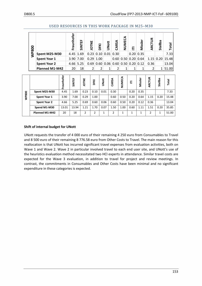
D800.5 CloudFlow (FP7-2013-NMP-ICT-FoF- 609100)
153
USED RESOURCES IN THIS WORK PACKAGE IN M25–M30
WP
80
0
Frau
nh
ofe
r
SIN
TEF
JOTN
E
DFK
I
UN
ott
CA
RSA
NU
MEC
A
ITI
Mis
sle
r
AR
CTU
R
Ste
llba
Tota
l
Spent M25-M30 4.45 1.69 0.23 0.10 0.01 0.30 0.20 0.35 7.33
Spent Year 1 3.90 7.00 0.29 1.00 0.60 0.50 0.20 0.64 1.15 0.20 15.48
Spent Year 2 4.66 5.25 0.69 0.60 0.06 0.60 0.50 0.20 0.12 0.36 13.04
Spend M1-M30 13.01 13.94 1.21 1.70 0.07 1.50 1.00 0.60 1.11 1.51 0.20 35.85
Planned M1-M42 20 18 2 2 1 2 1 1 1 2 1 51.00
Shift of internal budget for UNott
UNott requests the transfer of 4 000 euro of their remaining 4 250 euro from Consumables to Travel
and 8 500 euro of their remaining 8 776.58 euro from Other Costs to Travel. The main reason for this
reallocation is that UNott has incurred significant travel expenses from evaluation activities, both on
Wave 1 and Wave 2. Wave 2 in particular involved travel to each end user site, and UNott’s use of
the heuristics evaluation method necessitated two HCI experts in attendance. Similar travel costs are
expected for the Wave 3 evaluation, in addition to travel for project and review meetings. In
contrast, the commitments in Consumables and Other Costs have been minimal and no significant
expenditure in these categories is expected.
Frau
nh
ofe
r
SIN
TEF
JOTN
E
DFK
I
UN
ott
CA
RSA
NU
MEC
A
ITI
Mis
sler
AR
CTU
R
Stel
lba
Tota
l
Spent M25-M30 4.45 1.69 0.23 0.10 0.01 0.30 0.20 0.35 7.33
Spent Year 1 3.90 7.00 0.29 1.00 0.60 0.50 0.20 0.64 1.15 0.20 15.48
Spent Year 2 4.66 5.25 0.69 0.60 0.06 0.60 0.50 0.20 0.12 0.36 13.04
Planned M1-M42 20 18 2 2 1 2 1 1 1 2 1 51.00
WP
800
CloudFlow (FP7-2013-NMP-ICT-FoF- 609100) D800.5
154
OBJECTIVES (AS STATED IN GRANT AGREEMENT)
CloudFlow is managed by WP800 in administrative and financial terms. In addition, WP800 works
closely together with WP100, WP120 and WP130 to handle the management side of the competitive
calls, contract external partners, managing the payments in case of successful implementation of
(external) experiments.
The purpose of this work package is to coordinate the efforts of the consortium and to ensure the
progress of the project according to the work plan as well as the fulfilment of the consortium’s
contractual obligations. This includes the following features:
to coordinate and manage the project, and to take care of the relationship and regular
communication between project contractors and the EC
to assure timeliness and quality of results, refine and control fulfilment of project objectives
to identify, manage and review risk factors
to perform overall legal, contractual, financial and administrative management of the
consortium
to coordinate Intellectual Property Right (IPR)
TASK 800.1: PROJECT COORDINATION: FINANCIAL AND ADMINISTRATIVE MANAGEMENT
(AS STATED IN GRANT AGREEMENT)
The project coordination is concerned with administrative and planning tasks, which include:
to coordinate the project activities and to continuously check them against the project
objectives,
to ensure the correct evolution of the project providing administrative coordination,
to ensure the needed information/communication among the partners,
to collect, organize, edit and submit to the Commission all the contractual deliverables,
to call and chair the project internal meetings and prepare the minutes,
to prepare and call the progress review and auditing meetings,
if needed, to provide the definition and the implementation of redirection or recovery
actions,
to provide the necessary financial management for the project,
to manage Intellectual Property Rights (IPR),
to continuously evaluate and monitor the progress of experiments and status of
infrastructure,
to identify and manage risks,
to report achievements against project objectives and milestones,
to organize internal assessment of all project results and deliverables,
to define mechanisms and principles for reaching the specified objectives,
to coordinate Open Calls,
to interface to the European Commission,
to organize reviews and management meetings,
to manage the Consortium Agreement,
to handle contracting of new external partners and corresponding contract amendments.

D800.5 CloudFlow (FP7-2013-NMP-ICT-FoF- 609100)
155
COORDINATION AND MANAGEMENT TASKS ACCORDING TO THE GRANT AGREEMENT
The status of Coordinator tasks according to the Grant Agreement Annex II.2.3 is:
a) Financial contributions have been distributed to all partners in accordance with the grant
agreement and the decisions taken by the consortium.
b) Records are kept making it possible to determine at any time what portion of the financial
contribution of the European Union has been paid to each beneficiary for the purposes of
the project.
c) Reports have been reviewed to verify consistency with the project tasks before transmitting
them to the Commission,
d) The compliance by beneficiaries with their obligations under this grant agreement has been
monitored.
The status of management tasks according to the Grant Agreement Annex II.16.5 is:
The consortium agreement was signed by all partners. So far there have been no updates.
The competitive call for the second wave of experiments has been published, the submitted
proposals have been evaluated and seven new experiments have been selected.
The planning of the competitive calls for the third wave of experiments has started.
There have been no changes in the consortium and no changes of legal status of any partner.

CloudFlow (FP7-2013-NMP-ICT-FoF- 609100) D800.5
156
The following tables summarize the reported use of the person months w.r.t. to the reporting period
(M25-M30), the overall project (M1-M30) and the percentage used of all wave one partners.
Partner WP
100
WP
110
WP
111
WP
112
WP
113
WP
114
WP
115
WP
116
WP
120
WP
130
WP
200
WP
300
WP
400
WP
500
WP
600
WP
700
WP
800
Tota
l
M25
-M30
Pro
ject
tota
l
% u
sed
of
tota
l
01 Fraunhofer 0.48 7.00 1.50 2.75 2.75 0.95 2.10 4.45 21.98 114 19%
02 SINTEF 0.62 0.10 5.30 1.04 1.66 2.15 0.90 1.04 0.10 0.50 1.69 15.10 90 17%
03 JOTNE 0.07 0.18 1.79 0.07 0.23 2.34 30 8%
04 DFKI 2.50 0.30 0.80 0.50 0.30 0.37 0.45 0.70 0.10 6.02 46 13%
05 UNott 0.30 1.80 2.15 0.01 0.01 4.27 26 16%
06 CARSA 0.20 2.40 0.10 1.10 0.20 0.30 4.30 28 15%
07 NUMECA 24
08 ITI 0.08 0.20 0.40 0.60 2.30 0.50 0.50 0.20 4.78 24 20%
09 Missler 0.05 0.15 0.35 0.20 2.58 0.50 0.25 0.35 4.43 24 18%
10 ARCTUR 0.34 7.66 1.26 0.63 9.89 54 18%
11 Stellba 0.20 0.20 0.20 0.10 0.10 0.10 0.90 18 5%
Total M25-M30 2.07 0.17 0.35 0.55 0.20 0.10 0.30 0.10 26.84 1.44 5.95 9.64 4.55 6.81 2.72 4.89 7.33 74.01
Project total 13.50 12.50 6.40 6.00 7.40 6.00 7.80 6.40 54.20 5.50 56.00 70.00 62.00 47.00 33.00 33.00 51.00 478
% used of total 15% 1% 5% 9% 3% 2% 4% 2% 50% 26% 11% 14% 7% 14% 8% 15% 14% 15%
Reported use of Person Months per WP M25-M30
Partner WP
100
WP
110
WP
111
WP
112
WP
113
WP
114
WP
115
WP
116
WP
120
WP
130
WP
200
WP
300
WP
400
WP
500
WP
600
WP
700
WP
800
Tota
l
M01
-M30
Pro
ject
tota
l
% u
sed
of
tota
l
01 Fraunhofer 0.93 1.50 0.60 0.60 7.90 0.50 10.37 18.05 19.83 7.40 1.00 8.38 13.01 90.07 114 79%
02 SINTEF 1.00 1.60 1.40 6.60 1.54 6.79 13.15 15.55 8.90 1.30 2.59 13.94 74.36 90 83%
03 JOTNE 1.16 1.12 0.01 0.04 1.27 0.39 21.42 1.02 1.14 1.21 28.78 30 96%
04 DFKI 0.25 1.00 2.50 0.30 5.20 7.80 7.23 5.97 1.15 2.00 1.70 35.10 46 76%
05 UNott 2.29 3.00 1.00 1.00 1.00 1.00 1.00 1.00 2.99 0.05 3.40 0.07 0.07 17.87 26 69%
06 CARSA 0.60 1.00 7.50 0.10 11.65 1.65 1.50 24.00 28 86%
07 NUMECA 0.40 0.50 2.00 3.00 9.00 4.00 2.00 2.00 1.00 23.90 24 100%
08 ITI 0.48 0.40 2.00 3.05 5.78 3.40 1.70 1.10 0.60 18.51 24 77%
09 Missler 0.73 0.69 0.43 1.12 3.37 7.01 3.92 1.38 1.00 1.11 20.76 24 87%
10 ARCTUR 3.33 4.38 4.04 4.04 3.84 4.21 4.11 3.73 10.61 5.09 1.53 5.82 1.51 56.24 54 105%
11 Stellba 2.70 2.65 3.20 3.60 2.30 2.00 2.40 0.20 19.05 18 106%
Total M01-M18 13.87 15.19 8.13 9.36 10.48 9.38 9.71 8.53 38.49 2.49 50.15 63.15 48.39 36.99 22.73 25.75 35.85 408.64
Project total 13.50 12.50 6.40 6.00 7.40 6.00 7.80 6.40 54.20 5.50 56.00 70.00 62.00 47.00 33.00 33.00 51.00 478
% used of total 103% 122% 127% 156% 142% 156% 124% 133% 71% 45% 90% 90% 78% 79% 69% 78% 70% 86%
Partner WP
100
WP
110
WP
111
WP
112
WP
113
WP
114
WP
115
WP
116
WP
120
WP
130
WP
200
WP
300
WP
400
WP
500
WP
600
WP
700
WP
800
Tota
l
M01
-M30
01 Fraunhofer 93% 83% 100% 100% 88% 50% 80% 86% 83% 74% 50% 84% 65% 79%
02 SINTEF 100% 100% 100% 132% 154% 85% 77% 74% 89% 65% 65% 77% 83%
03 JOTNE 232% 373% 3% 10% 318% 78% 102% 51% 57% 61% 96%
04 DFKI 50% 67% 56% 60% 74% 87% 80% 85% 58% 67% 85% 76%
05 UNott 76% 100% 100% 100% 100% 100% 100% 100% 100% 5% 43% 7% 7% 69%
06 CARSA 60% 100% 100% 20% 83% 83% 75% 86%
07 NUMECA 80% 100% 100% 100% 100% 100% 100% 100% 100% 100%
08 ITI 96% 80% 100% 76% 72% 85% 85% 55% 60% 77%
09 Missler 146% 230% 43% 112% 84% 88% 98% 69% 50% 111% 87%
10 ARCTUR 167% 219% 202% 202% 192% 211% 206% 187% 43% 255% 38% 146% 76% 105%
11 Stellba 90% 133% 160% 180% 115% 100% 120% 20% 106%
Total M01-M06 103% 122% 127% 156% 142% 156% 124% 133% 71% 45% 90% 90% 78% 79% 69% 78% 70% 86%

157
The following diagrams depict the overall PM use and the PMs planned for the project on a per partner and a per WP perspective, repsectively.
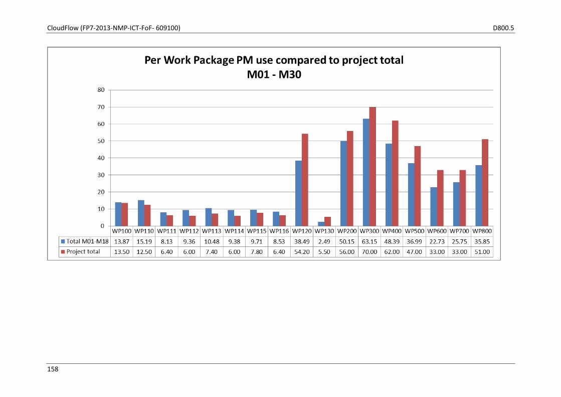
CloudFlow (FP7-2013-NMP-ICT-FoF- 609100) D800.5
158
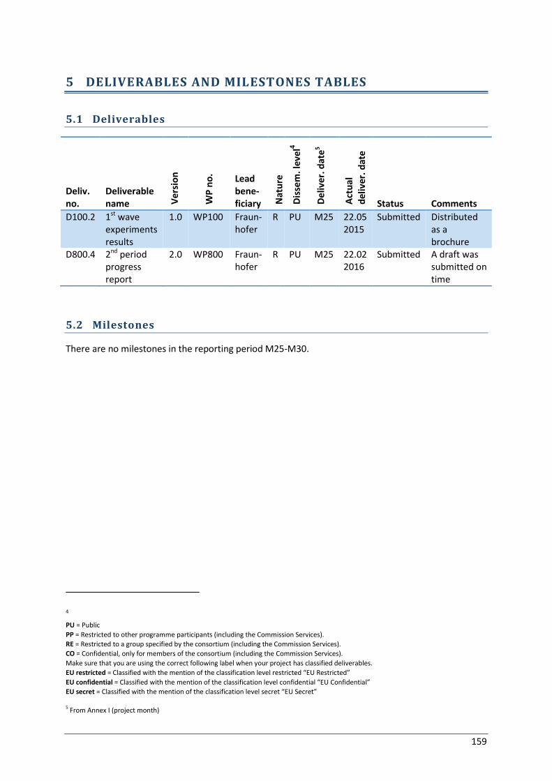
159
5 DELIVERABLES AND MILESTONES TABLES
5.1 Deliverables
Deliv. no.
Deliverable name V
ersi
on
WP
no
.
Lead bene-ficiary N
atu
re
Dis
sem
. lev
el4
De
liver
. dat
e5
Act
ual
d
eliv
er.
dat
e
Status Comments
D100.2 1st wave experiments results
1.0 WP100 Fraun-hofer
R PU M25 22.05 2015
Submitted Distributed as a brochure
D800.4 2nd period progress report
2.0 WP800 Fraun-hofer
R PU M25 22.02 2016
Submitted A draft was submitted on time
5.2 Milestones
There are no milestones in the reporting period M25-M30.
4 PU = Public
PP = Restricted to other programme participants (including the Commission Services).
RE = Restricted to a group specified by the consortium (including the Commission Services).
CO = Confidential, only for members of the consortium (including the Commission Services).
Make sure that you are using the correct following label when your project has classified deliverables.
EU restricted = Classified with the mention of the classification level restricted “EU Restricted”
EU confidential = Classified with the mention of the classification level confidential “EU Confidential”
EU secret = Classified with the mention of the classification level secret “EU Secret”
5 From Annex I (project month)

160
6 ANNEX: REPORT ON 2 ND OPEN CALL FOR APPLICATION EXPERIMENTS