3rv1 circuit breaker/msp - s3.amazonaws.com · 690 vac in acc. with iec 60 947-2 2-71 2.7.5...
TRANSCRIPT
2
3RV1 Circuit Breaker/MSP 1)
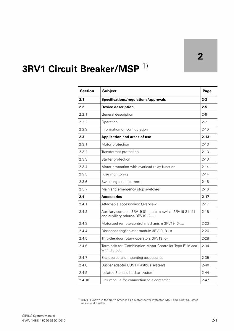
Section Subject Page
2.1 Specifications/regulations/approvals 2-3
2.2 Device description 2-5
2.2.1 General description 2-6
2.2.2 Operation 2-7
2.2.3 Information on configuration 2-10
2.3 Application and areas of use 2-13
2.3.1 Motor protection 2-13
2.3.2 Transformer protection 2-13
2.3.3 Starter protection 2-13
2.3.4 Motor protection with overload relay function 2-14
2.3.5 Fuse monitoring 2-14
2.3.6 Switching direct current 2-16
2.3.7 Main and emergency stop switches 2-16
2.4 Accessories 2-17
2.4.1 Attachable accessories: Overview 2-17
2.4.2 Auxiliary contacts 3RV19 01-.., alarm switch 3RV19 21-111 and auxiliary release 3RV19 .2-....
2-18
2.4.3 Motorized remote-control mechanism 3RV19 .6-.... 2-23
2.4.4 Disconnecting/isolator module 3RV19 .8-1A 2-26
2.4.5 Thru-the door rotary operators 3RV19 .6-.. 2-28
2.4.6 Terminals for "Combination Motor Controller Type E" in acc. with UL 508
2-34
2.4.7 Enclosures and mounting accessories 2-35
2.4.8 Busbar adapter 8US1 (Fastbus system) 2-40
2.4.9 Isolated 3-phase busbar system 2-44
2.4.10 Link module for connection to a contactor 2-47
1) 3RV1 is known in the North America as a Motor Starter Protector (MSP) and is not UL Listedas a circuit breaker
SIRIUS System ManualGWA 4NEB 430 0999-02 DS 01 2-1

3RV1 Circuit Breaker/MSP
2.5 Mounting and connection 2-48
2.5.1 Installation 2-48
2.5.2 Connection 2-49
2.5.3 Device circuit diagrams 2-51
2.6 Dimensional drawings (measurements in mm) 2-53
2.7 Technical specifications 2-64
2.7.1 General specifications 2-64
2.7.2 Permissible rating of approved devices for North America, u s 2-67
2.7.3 Short-circuit breaking capacity Icn in acc. with IEC 60 947-2 2-69
2.7.4 Limiter function with standard devices for 500 VAC and 690 VAC in acc. with IEC 60 947-2
2-71
2.7.5 Characteristics 2-71
2.7.6 Installation guidelines 2-72
2.8 Application notes for the use of 3RV1 downstream from
frequency converters/ inverter with pulsing voltage
2-73
2.8.1 Influences of high frequency currents upon the thermal overload release
2-73
2.8.2 Other possible influences 2-74
Section Subject Page
SIRIUS System Manual2-2 GWA 4NEB 430 0999-02 DS 01

3RV1 Circuit Breaker/MSP
2.1 Specifications/regulations/approvals
Standards • The 3RV1 circuit breaker/MSPs comply with the specifications for circuit breaker/MSPs in acc. with IEC 60947-2/DIN VDE 0660, Part 101.
• The circuit breaker/MSPs for motor protection comply with the specifica-tions in acc. with IEC 60947-4-1/DIN VDE 0660, Part 102.
• The auxiliary switches comply with IEC 60947-5-1/DIN VDE 0660 Part 200.
Approvals/
test reports
Confirmation of approvals, test certificates, and characteristics can be obtained on the Internet/intranet. underwww.siemens.de/lowvoltage/technical-assistance
Terminal markings The terminal markings comply with DIN EN 50 011.
Utilization categories Circuit breaker in acc. with IEC 60947-2: AMotor starter in acc. with IEC 60947-4-1: AC-3 (main conducting paths)DC - 11 / AC - 15 (control and auxiliary conducting paths)
Main and emergency
stop switches
The specifications for the main and emergency switches comply with IEC 60204/DIN VDE 0113 Part 1.
Disconnector
specifications
Disconnector specifications comply with IEC 60947-3.
Shock protection 3RV1 circuit breaker/MSPs are shockproof in acc. with DIN VDE 0106 Part 100, even without accessories. You can find additional information on the subject of shock protection in the "Switching, Protection and Distribution in Low-Voltage Networks" manual, p. 37 ff.
Degree of protection The degree of protection of the 3RV1 circuit breaker/MSP is IP20.In the terminal area of frame sizes S2 and S3, the degree of protection is IP00, when the lug kits are removed.
Characteristics The time-current characteristics, the current limitation characteristics and the I2t characteristics have been determined in acc. with IEC 60947 and DIN VDE 0660.
SIRIUS System ManualGWA 4NEB 430 0999-02 DS 01 2-3

3RV1 Circuit Breaker/MSP
Conditions of
application
Explosion-proof motors
For motor protection circuit breaker/MSP 3RV10, CLASS 10 and for motor protection circuit breaker/MSP with overload function 3RV11, CLASS 10:DIN VDE 0165 and EN 50 019, DMT-Certificate according to directive 94/9 EG (ATEX-Approval).
Nuclear power plants
KTA certificate
Railway vehicles
DIN EN 50 155
Ships and docks
Shipbuilding certificates of classes GL, LRS or DNV.
SIRIUS System Manual2-4 GWA 4NEB 430 0999-02 DS 01

3RV1 Circuit Breaker/MSP
2.2 Device description
3RV1 circuit breaker/MSPs are used to switch and protect three-phase induction motors of up to 45 kW at 400 V AC (100 HP at 600V AC) and for loads with rated currents of up to 100 A.
The 3RV1 circuit breaker/MSPs have 3 poles. To achieve the highest degree of flexibility, auxiliary switches, alarm switches, auxiliary releases, and other accessories can be easily attached to the circuit breaker/MSPs without tools.
3RV1 circuit breaker/MSPs and 3RT1 contactors work together both electri-cally and mechanically. This enables them to be easily and quickly put together to make load feeders.
Frame sizes 3RV1 circuit breaker/MSPs are available in 4 frame sizes (S00 to S3).
Fig. 2-1: 3RV1 circuit breaker/MSPs (frame sizes S00 to S3)
The following table shows you the frame sizes and the corresponding maxi-mum rated operational current at a voltage of 400 VAC. The last column in the table tells you which three-phase induction motor is suitable for which particular size.
S00 S0 S2 S3
Frame
sizeWidth
Max. rated operational
current
Output power of the
three-phase induction
motor
S00 45 mm 12 A 5.5 kW
S0 45 mm 25 A 11 kW
S2 55 mm 50 A 22 kW
S3 70 mm 100 A 45 kW
Table 2-1: circuit breaker/MSPs, frame sizes
SIRIUS System ManualGWA 4NEB 430 0999-02 DS 01 2-5

3RV1 Circuit Breaker/MSP
2.2.1 General description
Fields of application The 3RV1 circuit breaker/MSPs are suitable for:• Motor and plant protection• Starter protection (short-circuit protection)• Transformer protection• Fuse Monitoring
The 3RV16 11-0BD10 circuit breaker/MSP, frame size S00, is used for fuse monitoring.
Releases 3RV1 circuit breaker/MSPs have: • Inverse-time delay, thermal overload releases• Instantaneous short-circuit releases
The overload releases can be set to the load current.The short-circuit releases are set permanently to 13 times the rated current, which allows motors to start up without problems. Circuit breaker/MSPs used for transformer protection are set to 19 times the rated current to avoid being tripped by the high inrush current.When the circuit breaker/MSPs are tripped, in the case of frame size S00 the toggle switch goes into the tripped position, and in the case of frame sizes S0 to S3 the rotary switch switches to the tripped position. Before it is switched on again, the rotary switch must be put in the 0 position manually (reset) to avoid switching to the fault inadvertently.
In the case of circuit breaker/MSPs with a rotary switch, the tripping opera-tion can also be reported electrically by means of an alarm switch.
Tripping classes In acc. with IEC 947-4-1:• Frame sizes S00 to S3: class 10• Frame sizes S2/S3: class 20
Auxiliary release The circuit breaker/MSPs can also be equipped with one of the following auxiliary releases:• Shunt release• Undervoltage release• Undervoltage release with leading auxiliary contacts
Auxiliary contacts The 3RV1 can use a transverse auxiliary contacts and/or a side mounted auxiliary contacts (Section 2.4 Accessories).
Shock protection All frame sizes S00 to S3 are touch safe according to DIN VDE 0106 part 100. Additional protection covers are offered for frame sizes S2 and S3.• Frame size S2, S3: terminal covers for box terminals• Frame size S3: terminal covers for lug and bar connection
SIRIUS System Manual2-6 GWA 4NEB 430 0999-02 DS 01
3RV1 Circuit Breaker/MSP
Other accessories Other accessories for circuit breaker/MSPs:• Alarm switch• Disconnecting module• Isolated 3-phase busbar system• Busbar adapter• Rotary switches• Terminals for "Combination Motor Controller Type E" in acc. with UL 508• Housing and front plates
2.2.2 Operation
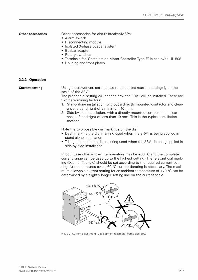
Current setting Using a screwdriver, set the load rated current (current setting) Ie on the scale of the 3RV1.The proper dial setting will depend how the 3RV1 will be installed. There are two determining factors:1. Stand-alone installation: without a directly mounted contactor and clear-
ance left and right of a minimum 10 mm.2. Side-by-side installation: with a directly mounted contactor and clear-
ance left and right of less than 10 mm. This is the typical installation method.
Note the two possible dial markings on the dial:• Dash mark: Is the dial marking used when the 3RV1 is being applied in
stand-alone installation • Triangle mark: Is the dial marking used when the 3RV1 is being applied in
side-by-side installation
In both cases the ambient temperature may be +60 °C and the complete current range can be used up to the highest setting. The relevant dial mark-ing (Dash or Triangle) should be set according to the required current set-ting. At temperatures over +60 °C current derating is necessary. The maxi-mum allowable current setting for an ambient temperature of +70 °C can be determined by a slightly longer setting line on the current scale.
Fig. 2-2: Current adjustment Ie adjustment (example: frame size S00)
360° o.k.
RV-0
0222
Ie
max. + 60 °C
max. + 70 °C
A
SIRIUS System ManualGWA 4NEB 430 0999-02 DS 01 2-7
3RV1 Circuit Breaker/MSP
Warning
The adjusting knob can be turned 360° clockwise. You can only turn it coun-terclockwise within the adjustment range. A setting over the marked current scale is not permitted
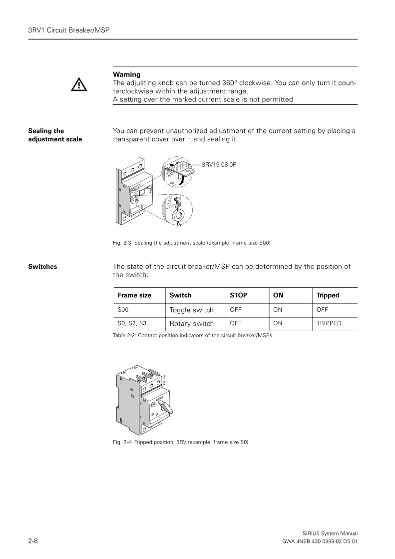
Sealing the
adjustment scale
You can prevent unauthorized adjustment of the current setting by placing a transparent cover over it and sealing it.
Fig. 2-3: Sealing the adjustment scale (example: frame size S00)
Switches The state of the circuit breaker/MSP can be determined by the position of the switch:
Fig. 2-4: Tripped position, 3RV (example: frame size S0)
3RV19 08-0P
Frame size Switch STOP ON Tripped
S00 Toggle switch OFF ON OFF
S0, S2, S3 Rotary switch OFF ON TRIPPED
Table 2-2: Contact position indicators of the circuit breaker/MSPs
RV-
0105
0
SIRIUS System Manual2-8 GWA 4NEB 430 0999-02 DS 01

3RV1 Circuit Breaker/MSP
Locking the circuit
breaker/MSPs
You can prevent the circuit breaker/MSP from being switched on by unau-thorized persons by securing the switching mechanism (toggle switch or rotary switch) with a padlock (shackle diameter 3.5 to 4.5 mm)The device can only be locked in the Off position.
Fig. 2-5: Locking the toggle and rotary switch (example: frame size S00 and S0)
Resetting after a tripping operation
When the circuit breaker/MSP trips, the switch goes into the tripped position. You use the switch to close the circuit again.In the case of frame sizes S0 to S3, the rotary switch must be manually turned to the OFF position after the device trips. Then the circuit breaker/MSP can be turned on again.In the case of frame sizes S2 and S3, it is possible to switch on and off using a motorized remote-control mechanism (see Section 2.4, Accessories).
Testing overload
tripping
The following table shows you how overload tripping of the circuit breaker/MSP can be tested:
Ø 3.5... 4.5 mm
RV-0
0251
S00 S0
Drawing Step Procedure
1 Switch the toggle switch/rotary switch from 0 to 1.
2/3 Put a screwdriver in the test opening and push it to the left.
Overload tripping is in working order when the toggle switch switches from 1 to 0 (frame size S00) or goes into the tripped position (frame sizes S0 to S3).
Table 2-3: Testing overload tripping (example: frame size S00)
1
2
RV-0
0223
SIRIUS System ManualGWA 4NEB 430 0999-02 DS 01 2-9

3RV1 Circuit Breaker/MSP
2.2.3 Information on configuration
Short-circuit protection The short-circuit releases of the 3RV1 circuit breaker/MSPs execute a three-phase isolation of the faulty branch circuit from the network and prevent any further damage.With a short-circuit breaking capacity of 50 kA or 100 kA a voltage of 400 VAC, the switches are considered to be short circuit-proof, since higher short-circuit currents are not to be expected where the switches are installed.Backup fuses are only required if the short-circuit current at the point of installation exceeds the rated short-circuit breaking capacity of the circuit breaker/MSPs.You will find the short-circuit breaking capacity for other voltages and the sizing of any required fuse listed in Section 2.7, Technical specifications.
Conditions of applica-
tion
3RV1 circuit breaker/MSPs are climate-proof. They are intended for use in closed areas where there are no hazardous operating conditions such as dust, corrosive fumes or destructive gases. Appropriate housings are available as an accessory for use in dusty and damp areas (see Section 2.4).
Selection Operational currents and starting currents can vary even in motors of the same power. The motor powers listed in the tables are to serve only as guide values. Most important when selecting the correct circuit breaker/MSPs are the specific starting data and rating of the motor to be protected. This also applies to circuit breaker/MSPs used for transformer protection.
Phase loss
sensitivity
The phase loss sensitivity of the circuit breaker/MSP ensures that it trips in the event of the loss of a phase and the resulting overcurrents in the other phases.During normal operation, the device should have a three-pole load. To pro-tect single-phase loads or direct current loads, all 3 main conducting paths should be switched in series
Explosion protection Note
In the case of a three-pole load, at 3 to 8 times the set current, the release time deviates by a maximum of ± 20% and therefore complies with the requirement of DIN VDE 0165 and EN 50019. The 3RV10 circuit breakers (MSP) for motor protection, CLASS 10, and the 3RV11 circuit breakers for motor protection with overload relay function, CLASS 10, have ATEX-Approval according to EU-requirement 94/9/EG (DMT-Certificate).
SIRIUS System Manual2-10 GWA 4NEB 430 0999-02 DS 01

3RV1 Circuit Breaker/MSP
Characteristics The tripping characteristic of the inverse-time delayed overload release (thermal overload release, a-release) is valid for direct current and alternat-ing current with frequencies of 0 to 400 Hz.
The characteristics are valid for tripping operations from a cold state. From a warm state, the release times can be reduced up to 75 % depending on the motor current and the ambient temperature.
The tripping characteristics of the instantaneous electromagnetic overcur-rent releases (short-circuit release, n-release) is based on the rated current In, which in the circuit breaker/MSPs with adjustable overload releases is also the upper value of the adjustment range.The following is a chart of the time-current characteristic:
Fig. 2-6: Time-current characteristic, chart
Time-current characteristics, current-limiting characteristics and I2t charac-teristics can be requested directly from your sales representative, if neces-sary.
10
5
2
1
10 000
5000
2000
1000
500
200
100
50
20
10
5
0,2
1
0,5
0,02
0,1
0,05
0,002
0,01
0,005
1006040
2
0,6 0,8 1 2 3 4 6 8 100,001
20 30 40 80 x n
NSB 00004amin
s
60Current
two-poleloadClass 10
three-poleloadClass 10
Opening time
three-poleloadClass 20
SIRIUS System ManualGWA 4NEB 430 0999-02 DS 01 2-11

3RV1 Circuit Breaker/MSP
Frequency sensitivity of
the short-circuit
releases
The characteristics of the short-circuit releases apply to frequencies of 50/60 Hz. For lower frequencies, such as 16 2/3 Hz, for higher frequencies up to 400 Hz, and for direct current, appropriate correction factors have to be taken into account.The following characteristic curve illustrates the frequency sensitivity of the short-circuit releases:
Fig. 2-7: Frequency sensitivity of the short-circuit releases
The increase in tripping current is approximately 40 % for DC voltage.
40
30
20
10
0
-10
-20
-300 50 100 200 250 300 350 400 Hz150
Tripping currentChange in %
SIRIUS System Manual2-12 GWA 4NEB 430 0999-02 DS 01

3RV1 Circuit Breaker/MSP
2.3 Application and areas of use
The tripping characteristics of the 3RV1 circuit breaker/MSPs are designed primarily to protect three-phase induction motors. The circuit breaker/MSPs are therefore also referred to as motor protecting switches. In Europe, the 3RV10 circuit breaker/MSPs for motor protection can also be used in the protection of systems.
2.3.1 Motor protection
Current setting The current of the motor that is to be protected is set on the adjustment scale. This sets the integrated overload protection of the motor current. The short-circuit release is set at the factory to 13 times the value of the rated current (the highest value on the current scale) of the circuit breaker/MSP. This ensures problem-free startup and reliable protection of the motor.
Phase loss
sensitivity
The phase loss sensitivity of the circuit breaker/MSP ensures that it trips in the event of the loss of a phase and the resulting overcurrents in the other phases.
CLASS10/CLASS20 Circuit breaker/MSPs of frame sizes S00 to S3 (0-100 A) with thermal over-load releases comply with tripping class 10 (CLASS 10). Circuit breaker/MSPs with the CLASS 20 tripping characteristic are also available for frame sizes S2 and S3 (11-100 A) for longer startup conditions.
2.3.2 Transformer protection
Inrush current In the case of primary protection of control transformers, the high inrush currents that occur when the transformers are switched on often result in the unwanted tripping of the protective devices.Therefore, the 3RV14 circuit breaker/MSPs have overcurrent releases for the protection of transformers that are set at the factory to approximately 19 times the rated current. This makes it possible to protect transformers in which the inrush currents reach peak values of up to 30 times the rated cur-rent with circuit breaker/MSPs in the primary circuit. The 3RV14 for trans-former protection come in frame sizes S0 and S2 (0 to 40 A).
In the case of control transformers with low inrush current (SIEMENS 4AM control transformers, for example), this is not required. 3RV10 circuit breaker/MSPs can be used. In these lower inrush applications the 3RV14 devices are not UL listed for the protection of transformers.
2.3.3 Starter protection The 3RV13 starter protection switches are circuit breakers without overload releases. They are used together with a contactor and overload relay if the circuit breaker/MSP is not to be triggered in the case of overload tripping. Like the 3RV10 the short-circuit release is set at 13 times the rated current. The 3RV13 are available in frame sizes S0 to S3 (0 to 100 A).
SIRIUS System ManualGWA 4NEB 430 0999-02 DS 01 2-13

3RV1 Circuit Breaker/MSP
2.3.4 Motor protection with overload relay function
3RV11 circuit breakers/MSPs with the overload relay function are available for frame sizes S0, S2, and S3.
Description The 3RV11 devices have the same overload and short-circuit trip characteris-tics as the 3RV10. However the overload release doesn’t effect the switch-ing mechanism of the circuit breaker/MSP. In the event of an overload, the circuit breaker/MSP remains switched on.The overload release uses two side mounted auxiliary contacts (1NO + 1NC), that switch in the event of an overload. The auxiliary contacts can be used for signalling or can be used to disconnect a downstream con-tactor. After the circuit breaker/MSP has cooled down, the auxiliary contacts are reset automatically.
Caution
In the overload range, the circuit breaker/MSP does not protect itself with the overload relay function. You must therefore ensure that the power is safely disconnected by means of a downstream switching device (e.g. a contactor).
Fixed link: auxiliary
contacts with circuit
breaker/MSP
Note The auxiliary contacts are factory mounted to the 3RV11 circuit breaker/MSP on the right side and cannot be removed.
Diagrams
Fig. 2-8: Circuit breaker/MSP with overload relay function (frame sizes S0 to S3)
2.3.5 Fuse monitoring
The 3RV16 11-0BD10 circuit breaker/MSP is used with frame size S00 for fuse monitoring.A conducting path of the circuit breaker/MSP is switched in parallel for each fuse. If one fuse fails, the current flows via the parallel-switched conducting path of the circuit breaker/MSP and trips it.
Warning
Fuse monitoring using the 3RV16 11-0DB10 circuit breaker/MSP is not per-missible in feeders with power control regulators where a DC feedback with higher values can occur in the event of a fault.
S0: 3RV11 21-.... S2: 3RV11 31-.... S3: 3RV11 42-....
TEST
RV-0
0588
TEST
RV-00589
TEST
SIRIUS System Manual2-14 GWA 4NEB 430 0999-02 DS 01

3RV1 Circuit Breaker/MSP
Auxiliary switch func-
tions
The circuit breaker/MSP used for fuse monitoring can be equipped with a transverse or lateral auxiliary switch (Section 2.4, Accessories). The auxiliary switch reports the tripping of the circuit breaker/MSP and thus the failure of the fuse and initiates an all-pole disconnection of the problem circuit by a corresponding switching device.
Safety sign Note
When fuses used for isolation purposes are monitored, a warning sign must be put up next to them. Via the parallel-switched voltage circuit of the moni-toring facility, voltage may get into the area that is supposed to be isolated if the monitoring equipment has not been disconnected.
We suggest the following text for the warning:
Voltages The 3RV16 11-0DB10 circuit breaker/MSP is suitable for fuse monitoring in the following voltage ranges:• 24 to 690 VAC, 50/60 Hz • 24 to 250 VDC, 100 to 600 VDC
Switching capacity ICN 100 kA
Circuit diagrams
Fig. 2-9: Circuit diagrams of circuit breaker/MSPs for fuse monitoring
Parallel cables/meshed
networks
Attention
In the case of parallel cables and meshed networks, a tripping operation and signal only occurs when the voltage difference at the circuit breaker/MSP is at least 24 V.
Attention
To ensure isolation, also disconnect the fuse-monitoring device with the item designation............
Ue AC 24 ... 690V DC 24 ... 250V DC 100 ... 600V
I»I» I» I»I» I» I»I» I»
SIRIUS System ManualGWA 4NEB 430 0999-02 DS 01 2-15
3RV1 Circuit Breaker/MSP
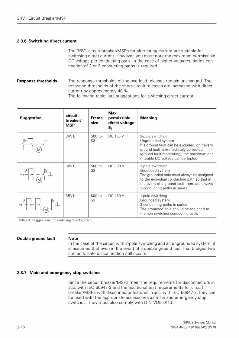
2.3.6 Switching direct current
The 3RV1 circuit breaker/MSPs for alternating current are suitable for switching direct current. However, you must note the maximum permissible DC voltage per conducting path. In the case of higher voltages, series con-nection of 2 or 3 conducting paths is required.
Response thresholds The response thresholds of the overload releases remain unchanged. The response thresholds of the short-circuit releases are increased with direct current by approximately 40 %. The following table lists suggestions for switching direct current:
Double ground fault Note In the case of the circuit with 2-pole switching and an ungrounded system, it is assumed that even in the event of a double ground fault that bridges two contacts, safe disconnection still occurs.
2.3.7 Main and emergency stop switches
Since the circuit breaker/MSPs meet the requirements for disconnectors in acc. with IEC 60947-3 and the additional test requirements for circuit breaker/MSPs with disconnector features in acc. with IEC 60947-2, they can be used with the appropriate accessories as main and emergency stop switches. They must also comply with DIN VDE 0113.
Suggestioncircuit
breaker/
MSP
Frame
size
Max.
permissible
direct voltage
EI
Meaning
3RV1. S00 to S3
DC 150 V 2-pole switchingUngrounded systemIf a ground fault can be excluded, or if every ground fault is immediately corrected (ground-fault monitoring), the maximum per-missible DC voltage can be tripled.
3RV1. S00 to S3
DC 300 V 2-pole switchingGrounded systemThe grounded pole must always be assigned to the individual conducting path so that in the event of a ground fault there are always 2 conducting paths in series.
3RV1. S00 to S3
DC 450 V 1-pole switchingGrounded system3 conducting paths in series.The grounded pole should be assigned to the non switched conducting path.
Table 2-4: Suggestions for switching direct current
L-
M
L+
L-L
M
+
L-L
M
+
SIRIUS System Manual2-16 GWA 4NEB 430 0999-02 DS 01

3RV1 Circuit Breaker/MSP
2.4 Accessories
2.4.1 Attachable accessories: Overview
Auxiliary switches, alarm switches, auxiliary releases and other accessories can be easily attached to the circuit breaker/MSPs without tools, as required.
Accesso-
ries
Function/use Width Attach
to
Transverse
auxiliary
switch
The contacts of the auxiliary switches close and open together with the main contacts of the circuit breaker/MSP. Variants:• 1 changeover contact• 1 NO + 1 NC contact• 2 NO contacts
Width of the circuit breaker/MSP remains the same
Front
Electroni-
cally opti-
mized
transverse
auxiliary
switch
One transverse auxiliary switch can be attached for each circuit breaker/MSP:Variants:• 1 changeover contact
Lateral
auxiliary
switch
One lateral auxiliary switch can be attached for each circuit breaker/MSP:• 1 NO + 1 NC contact • 2 NO contacts • 2 NC contacts• 2 NO + 2 NC contacts
9 mm
18 mm
Left side
Alarm
switch
Frame sizes S0, S2 and S3
One alarm switch can be attached at the side of the circuit breaker/MSPs with rotary switches.
The alarm switch has two contact systems:• One contact system (1 NO + 1 NC) reports a general
tripping operation, irrespective of whether it was caused by a short circuit, overload or auxiliary release.
• The other contact system (1 NO + 1 NC) only switches in the event of a short circuit tripping operation.
To reset the circuit breaker/MSP after a short circuit, the alarm switch must be reset manually after the cause of the error has been eliminated.
18 mm
Shunt
release
Remote release of the circuit breaker/MSP:• Via PLC: The coil of the release should be connected to the volt-
age only briefly• Especially suitable for emergency stop disconnection by means
of appropriate emergency stop switches in acc. with DIN VDE 0113
18 mm Right side
Accesso-ries can-not be attached on the right of a circuit breaker/MSP with a relay function.(3RV11)
Undervolt-
age
release
Trips the circuit breaker/MSP in the event of a voltage interruption (e.g. when the power plug is removed) and prevents the motor starting up inad-vertently when the voltage returns.
Undervolt-
age release
with lead-
ing
auxiliary
contacts
2 NO
Function and use, see undervoltage release. Additional function:The auxiliary contacts isolate the undervoltage release from the power system on both sides in the event of breaking or a tripping operation and thus prevent voltage distortion to the control circuit when the switch is in the off position.It is possible to reset the circuit breaker/MSP because the contacts reset.
Table 2-5: Attachable accessories
SIRIUS System ManualGWA 4NEB 430 0999-02 DS 01 2-17

3RV1 Circuit Breaker/MSP
2.4.2 Auxiliary contacts 3RV19 01-.., alarm switch 3RV19 21-111 and auxiliary release 3RV19 .2-....
The maximum configuration for each 3RV1 circuit breaker/MSP is one trans-verse auxiliary contact, one side mounted auxiliary contact with 2 contacts, one alarm switch, and one auxiliary release. An alternative to the transverse auxiliary contacts and one side mounted auxiliary contact with 2 contacts would be to use a side mounted auxiliary contact with 2 NO + 2 NC. So with any one circuit breaker/MSP a maximum of 4 auxiliary contacts with auxiliary release can be used.
Possible combinations The following combinations of auxiliary switches and alarm switches or of auxiliary switches are possible:• Auxiliary contacts with 2 contacts and alarm switches can be installed
individually or together. The side-mounted auxiliary contact is installed on the left of the alarm switch.
• Transverse and lateral auxiliary switches can be combined. Maximum of 4 auxiliary contacts is possible.
• One auxiliary release can be attached on the right for each circuit breaker/MSP
Accesso-
ries
Function/use Width Attach
to
Discon-
necting
module
Frame sizes S0 and S2
The supply is fed to the circuit breaker/MSP via the disconnecting module. A connector which can only be removed when the circuit breaker/MSP is switched off isolates the circuit breaker/MSP from the power system on 3 poles. The shock-protected isolation position is easily visible and is secured by a padlock to ensure that the connector cannot be used during maintenance work, for example.
Width of the circuit breaker/MSP remains the same
Upper side/ line side
Motorized
remote-
control
mechanism
For frame sizes S2 and S3
The circuit breaker/MSPs can be opened and closed via the remote-con-trolled mechanism by means of electrical commands. This enables a load or system to be disconnected from and then reconnected to the power system from an operator control panel.The circuit breaker/MSP can be locally disconnected from and recon-nected to the remote-control mechanism.
148 mm —
Rotary
switch
extension
for the door
The rotary switch extension for the door consists of a knob, a drive cou-pling and an extension shaft. They comply with IP65. The door interlock prevents the enclosure door being opened inadvertently when the switch is in the on position. The off position can be secured with a maximum of 3 padlocks.
Depends on the applica-tion
Front mount
Table 2-5: (cont.) Attachable accessories
SIRIUS System Manual2-18 GWA 4NEB 430 0999-02 DS 01

3RV1 Circuit Breaker/MSP
Mounting the
auxiliary contacts
The auxiliary switches, alarm switches, and auxiliary releases are mounted in the same way for all frame sizes:
Transverse auxiliary contacts (3RV19 01-1D, -1E, -1F, -1G, -2E)
Fig. 2-10: Mounting the transverse auxiliary switch (frame size S00)
Side-mounted auxiliary contacts (3RV19 01-..)
Undervoltage release (3RV19 .2-....)
Fig. 2-11: Mounting/removing the side mount auxiliary contacts/undervoltage release (example: frame size S00)
3RV1901-1D3RV1901-.E3RV1901-1F3RV1901-1G2
1
3 41
2
RV-0
1084
3RV1901-.A3RV1901-.B3RV1901-.C3RV1901-.J
1
2
13RV19.2-1A..
2
3RV19.2-1C..3RV19.2-1D..
2
3
3
3
1
1
SIRIUS System ManualGWA 4NEB 430 0999-02 DS 01 2-19

3RV1 Circuit Breaker/MSP
Voltage ranges of the
auxiliary releases
One undervoltage release or shunt release can be installed for each circuit breaker/MSP. The following voltage ranges are possible:
Auxiliary release Frequency
Undervoltage release DC
24 V
AC 50 Hz AC 60 Hz
24 V110 V
—230 V400 V415 V500 V
—120 V208 V240 V
—480 V
—
Undervoltage release with leading auxiliary contacts 2NO
230 V400 V415 V
240 V—
480 V
Shunt release AC 50/60 Hz
100 % ED 1)
1)Transformer operational voltage of the lower mark of the voltage range at 0.85 (Tu = 60 °C) is valid for 100% (continuous) duty cycle only at AC 50/60 Hz
AC 50/60 Hz; DC
5 sec.. ED 2)
2)Transformer operational voltage of the lower mark of the voltage range at 0.9 (Tu = 60 °C) is valid for 5 seconds duty cycle at AC 50/60 Hz and DC
20 – 24 V90 – 110 V
200 – 240 V350 – 415 V
500 V
20 – 70 V70 – 190 V
190 – 330 V330 – 500 V
500 V
Table 2-6: Voltage ranges of the auxiliary releases
SIRIUS System Manual2-20 GWA 4NEB 430 0999-02 DS 01

3RV1 Circuit Breaker/MSP
Mounting the alarm
switch
The following table explains how the 3RV19 21-1M alarm switch is mounted onto the circuit breaker/MSP: (Frame size S0, S2 and S3):
Drawing Step Procedure
1 Press and hold down the trans-port safety button on the inside of the alarm switch.
2 Then press the blue RESET but-ton on the front of the alarm switch.
3 Hook the alarm switch onto the circuit breaker/MSP.
4 Move the alarm switch towards the circuit breaker/MSP until you hear it click into place.
Table 2-7: Testing overload tripping (example: frame size S0)
2
3
1 2
3RV 19 21-1M
3
4
SIRIUS System ManualGWA 4NEB 430 0999-02 DS 01 2-21

3RV1 Circuit Breaker/MSP
Alarm switch (signal-
ling switch) signals
The alarm switch has two signals:
• Tripped (Short-circuit, overload or tripping through a shunt trip)• Short circuit signal (Short circuit only)
The following table lists the signals, the status of the alarm switch, and the procedure required:
Drawing Status Procedure
Tripped signal
Circuit breaker/MSP is in the tripped positionAlarm switch:LED is RedRESET button (blue): remains depressed
Switch off (Off position) andthen switch on again (On posi-tion of the circuit breaker/MSP)
Short circuit
Circuit breaker/MSP is in the tripped positionAlarm switch:LED is RedRESET button (blue): pushed out
Push in the RESET-button (blue) on the Alarm switch then switch the circuit breaker/MSP off (Off posi-tion) andthen switch it back on again (On position of the circuit breaker/MSP)
Table 2-8: Alarm switch with tripped signal and short circuit signal
21
SIRIUS System Manual2-22 GWA 4NEB 430 0999-02 DS 01
3RV1 Circuit Breaker/MSP
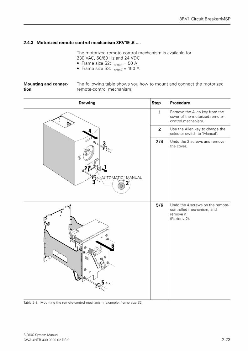
2.4.3 Motorized remote-control mechanism 3RV19 .6-....
The motorized remote-control mechanism is available for 230 VAC, 50/60 Hz and 24 VDC• Frame size S2: Inmax = 50 A• Frame size S3: Inmax = 100 A
Mounting and connec-
tion
The following table shows you how to mount and connect the motorized remote-control mechanism:
Drawing Step Procedure
1 Remove the Allen key from the cover of the motorized remote-control mechanism.
2 Use the Allen key to change the selector switch to "Manual".
3/4 Undo the 2 screws and remove the cover.
5/6 Undo the 4 screws on the remote-controlled mechanism, and remove it. (Pozidriv 2).
Table 2-9: Mounting the remote-control mechanism (example: frame size S2)
1
3
3
4
2MANUALAUTOMATIC
2
5 (4 x)
6
SIRIUS System ManualGWA 4NEB 430 0999-02 DS 01 2-23

3RV1 Circuit Breaker/MSP
7 Screw the frame onto the mount-ing surface using 4 screws M4 (Frame size S2), M5 (Frame size S3)
8/9 Attach the circuit breaker/MSP using 2 screws. Attention: Use screws 14 mm in length.
10 Attach the ground wire.
11 Connect the main and control wires to the circuit breaker/MSP.
12 If desired, set MANUAL RESET: Remove the screw from the RESET lever.
13-15 Put the remote-control mecha-nism module into place, making sure that the driver covers the knob on the circuit breaker/MSP, and screw it on.
Drawing Step Procedure
Table 2-9: (cont.) Mounting the remote-control mechanism (example: frame size S2)
7
9
97
8
S2: M4 / S3: M5
M5 (4 x)
3RV19 21-1M
15
12
Manual-RESET
14
13
(4 x)
Automatic-RESET
10
11
SIRIUS System Manual2-24 GWA 4NEB 430 0999-02 DS 01

3RV1 Circuit Breaker/MSP
Warning
Do not set the "Automatic" position or operate the remote-control mecha-nism when open! There is a risk of injury!
Manual RESET Remove the screw from the RESET lever (step 12)
16-18 Screw the control wires for the remote-control mechanism onto the connector, and insert it.
19 Set the current.
20/21 Put the cover on, and screw it tightly.
22 Use the Allen key to switch to AUTOMATIC and replace the Allen key in the cover.
Drawing Step Procedure
Table 2-9: (cont.) Mounting the remote-control mechanism (example: frame size S2)
16
17
21
21 22
(22)
20
18
19
UC
SIRIUS System ManualGWA 4NEB 430 0999-02 DS 01 2-25

3RV1 Circuit Breaker/MSP
2.4.4 Disconnecting/isolator module 3RV19 .8-1A
The disconnecting/isolator module is suitable for creating a visible isolating distance. The isolating connector can only be removed in a deenergized state. The isolating distance can be secured with padlocks when open.Disconnecting modules are available for the circuit breakers/MSPs of frame sizes S0 and S2.
Mounting sequence for
the disconnecting/iso-
lator module and
Transverse auxiliary
contacts
Attention
The disconnecting/isolator module covers the terminal screws of the trans-verse auxiliary switch. We therefore recommend that you use the lateral auxiliary switches or that you only install the disconnecting module once the transverse auxiliary switch has been wired.
Mounting The modules are mounted in the same way for frame sizes S0 and S2. The following diagrams show you how to mount the disconnecting module. Example shown for frame size S0 (3RV1928-1A):
Fig. 2-12: Mounting the disconnecting module (frame size S0)
1
3
2
3RV19 28-1A
3RV1. 2
54
7
8
86
SIRIUS System Manual2-26 GWA 4NEB 430 0999-02 DS 01

3RV1 Circuit Breaker/MSP
Disconnecting and
locking
The disconnecting/isolator module can be locked and sealed or secured with two padlocks if the connector is removed during maintenance work, for example. The disconnecting/isolator module for frame size S0 (3RV19 28-1A) can use a padlock with a max. locking arm diameter of 6 mm, for frame size S2 (3RV19 38-1A) a padlock with a max. locking arm diameter of 9 mm can be used. The circuit breaker/MSP itself can also be secured with a third padlock.
Fig. 2-13: Locking the disconnecting module (frame size S0)
Terminal cover
(frame size S2)
A terminal cover (3RT1936-4EA2) is available for the disconnecting module in frame size S2 (3RV1938-1A) that protects the contacts from dirt and pro-vides additional shock protection.
Fig. 2-14: Locking the disconnecting module and mounting the cover (frame size S2)
1
3
25
54
4
3RV19 38-1A
4
2
1
33RT19 36-4EA2
3RV1. 3
SIRIUS System ManualGWA 4NEB 430 0999-02 DS 01 2-27
3RV1 Circuit Breaker/MSP
2.4.5 Thru-the door rotary operators 3RV19 .6-..
Thru-the-door rotary operators are available for frame sizes S0, S2, and S3. They consist of a lockable rotary handle with a detachable door coupling, an extension shaft, and a connector for the switch drive. There are two basic designs available. The thru-the-door rotary operator 3RV19 26-0. for standard applications and the thru-the-door rotary operator 3RV19 .6-2. for harsh conditions. Both designs have an IP65 rating and can be locked in the OFF-position with up to three padlocks.Both operators are available with either black/grey and/or red/yellow for emergency-stop handle styles.The thru-the-door rotary operator for harsh conditions also meet the discon-nection requirements according to IEC 60 947-2.
SIRIUS System Manual2-28 GWA 4NEB 430 0999-02 DS 01

3RV1 Circuit Breaker/MSP
Thru-the door rotary operator 3RV19 26-0.
Mounting
Fig. 2-15: Mounting the thru-the-door rotary operator 3RV19 26-0., (example: Frame size S2)
67
min. 16 mmmax. 20 mm
3
1
2
4
5
3RV19 26-0B, -0C: 130 mm3RV19 26-0K, -0L: 330 mm
0.7 ... 0.9 Nm
SIRIUS System ManualGWA 4NEB 430 0999-02 DS 01 2-29

3RV1 Circuit Breaker/MSP
Opening the door The following table shows you how the cubicle door can be opened using the thru-the-door rotary operator:
Opening the door with
great force
Note
If the circuit breaker/MSP is in the ON position and the door is opened with a force >150 N to 200 N, the cap of the extension shaft is separated from the rotary switch of the circuit breaker/MSP to prevent the circuit breaker/MSP being destroyed.The circuit breaker/MSP remains in the ON position.
Fig. 2-16: Operation note: Thru-the-door rotary operator 3RV19 26-0.,
Drawing Procedure
To open the cubicle door, set the circuit breaker/MSP to O (OFF). This releases the extension shaft from the rotary switch and allows the door to be opened.
If you want to open the enclosure door during operation, you can override the procedure by press-ing the button at the side of the rotary knob (step 1).To close it during operation, press the button again so that the exten-sion shaft snaps into place again.
Table 2-10: Opening a enclosure door using the thru-the-door rotary operator
2
1
1
2
ca.150 ... 200 N
SIRIUS System Manual2-30 GWA 4NEB 430 0999-02 DS 01

3RV1 Circuit Breaker/MSP
The extension shaft must then be remounted on the circuit breaker/MSP and the rotary switch extension for the door as follows:
Locking When the rotary switch is in the OFF position, it can be secured with up to 3 padlocks (e.g. during maintenance work on the system).
Fig. 2-17: Locking the thru-the-door rotary operator
Drawing Step Procedure
1 Switch the circuitbreaker off, and turn
the rotary switch on the door to OFF.
2 Put the cap of the extension shaft on the rotary switch of the cir-cuit breaker/MSP, and put the extension shaft in the cap.
3 Close the enclosure door.
Table 2-11: Mounting the extension shaft
1
3
2
1
1
2
max.ø 8 mm
SIRIUS System ManualGWA 4NEB 430 0999-02 DS 01 2-31

3RV1 Circuit Breaker/MSP
Thru-the door rotary operator for harsh conditions 3RV19 .6-2.
Mounting
Fig. 2-18: Mounting the thru-the-door rotary operator 3RV19 .6-2., (example: frame size S0 and S2)
8
7
RV-0
0593
6
5
RV-0
0592
3RV19 36: M43RV19 46: M5
1.2 ... 1.5 Nm
1.2 ... 1.5 Nm
1
2
RV-0
0590 RV
-005
91
3
4
RV-0
0594
A (mm) B (mm)3RV19 26 50 1113RV19 36 60 1603RV19 46 60 185
C (mm) D (mm)3RV19 26 163 4633RV19 36 215 5153RV19 46 240 540
∅ 46 ±4
∅ 4.5
RV-0
0596
1.1 - 1.3 Nm
M4: 2.6 - 3 Nm
10
9
(4 x)
11
Mount the 3RV1 frame size S0 by simply snapping it on theDIN rail
Frame size S0
Frame size S2/S3
Mount the 3RV1 Frame size S2/S3 by panel mounting (2 x)
SIRIUS System Manual2-32 GWA 4NEB 430 0999-02 DS 01

3RV1 Circuit Breaker/MSP
Opening the door In order to open the enclosure door, turn the handle in the Off position. The extension shaft disengages from the handle in this position and the door can be opened.
Opening the door with
great force
Note
When the circuit breaker/MSP is in the On position (”I“-position) and the door is opened with a force of ≥ 800 Nm, the operator can be destroyed. In this case the circuit breaker/MSP remains turned on. Anything under a force of 800 Nm, the operator will remain locked to the door.
Locking
Fig. 2-19: Locking the thru-the-door rotary operator (example: frame size S0)
The operator handle can be padlocked inside the enclosure. To do this the circuit breaker/MSP must be in the Off position.
Fig. 2-20: Locking the thru-the-door rotary operator outside the enclosure
The operator can also be locked from outside the enclosure on the rotary handle.To do this the circuit breaker/MSP must first be in the Off position. Then pull out the retractable locking device that is built in the handle. This locking device can hold up to five padlocks with a maximum locking arm diameter of 6 mm or three padlocks with a maximum locking arm diameter of 8.5 mm.
∅ 3.5 ... 4.5 mm
RV-0
0595
1
2
12
SIRIUS System ManualGWA 4NEB 430 0999-02 DS 01 2-33

3RV1 Circuit Breaker/MSP
2.4.6 Terminals for "Combination Motor Controller Type E" in acc. with UL 508
Since July 16, 2001, 1 inch air clearance and 2 inch creepage distance is required for "Combination Motor Controller Type E" on the input side in acc. with UL 508. For the 3RV10 circuit breakers/MSPs frame size S0 use termi-nal block 3RV1928-1H and for frame sizes S3 use terminal block 3RT1946-4GA07. The 3RV10 in frame size S2 complies with the required air clearance and creepage distance without a terminal block.These terminal blocks cannot be used in the S0 frame size at the same time as the 3RV19.5 3-phase busbars or in the S3 frame size at the same time as a transverse auxiliary switch.
Attention
Terminal blocks are not required for use in acc. with CSA.
Fig. 2-21: Terminals for "Combination Motor Controller Type E"
3RV19 28-1H
Self-Protected Combination Controller Type E
3RT19 46-4GA07
1
2
S3S0
SIRIUS System Manual2-34 GWA 4NEB 430 0999-02 DS 01

3RV1 Circuit Breaker/MSP
2.4.7 Enclosures and mounting accessories
Molded-plastic enclosures (IP55) are available if you want to install circuit breakers/MSPs as single units. All the enclosures are equipped with neutral and ground terminals. Above and below are two openings that can be knocked out for cable glands. On the back of the enclosure there are 2 precut openings. All the cable bushings have metric dimensions. The sur-face casings can be sealed. There is space in the enclosure on the rail for additional modular terminal blocks.
Widths The widths of the enclosures depend on whether auxiliary releases are used:• 54 mm: circuit breaker/MSP + side-mount auxiliary contact • 72mm/82 mm: circuit breaker/MSP + side-mount auxiliary contact+ auxil-
iary release
Mounting the
surface mount enclo-
sure
Fig. 2-22: Molded-plastic surface mount enclosure (frame size S00)
ModelMolded-
plastic...Width Frame size
Enclosure with actuator membrane for toggle switch
Surface mount 54 mm, 72 mm S00
Flush mount 72 mm S00
Lockable enclosure with rotary switch Surface mount 54 mm, 72 mm82 mm
S0S2
Flush mount 72 mm S0
Lockable enclosure with emergency stop rotary switch (red/yellow)
Surface mount 54 mm, 72 mm82 mm
S0S2
Flush mount 72 mm S0Table 2-12: Enclosures for 3RV1 circuit breakers/MSPs
3
41
2
Neutral/ground terminals
SIRIUS System ManualGWA 4NEB 430 0999-02 DS 01 2-35

3RV1 Circuit Breaker/MSP
Mounting the
flush mount enclosure
Fig. 2-23: Molded plastic flush mount enclosure (example: frame size S00)
Front plates Molded-plastic-front plates with IP55 degree of protection are suitable for any housing:
4
4
5
1
2 23
3
1
Front plates
and
accessories
ModelFrame
size
Front plates With actuator membrane and support for switch
S00
With lockable rotary switch S0, S2, S3
With lockable emergency-stop rotary switch (red/yellow)
S0, S2, S3
Accessories Support for front plate S0
Table 2-13: Front plates for any housings
SIRIUS System Manual2-36 GWA 4NEB 430 0999-02 DS 01

3RV1 Circuit Breaker/MSP
Mounting the front plates
Frame size S00
Fig. 2-24: Mounting the front plate (example: frame size S00)
Frame sizes S0, S2, S3
Fig. 2-25: Mounting the front plate (example: frame size S0)
3RV19 13-4C 3RV19 13-4B
e.g.
Enclosure door6
5
43
5
2
M6
M31
VU-0
1015
65
43
5
2
M6
M3
e.g. Enclosure doorM3
4
1
2
3
3RV19 23-4G
3RV19 23-4.
M3
2
1
a3RV1. 2 86.53RV1. 3 139.03RV1. 4 164.5
3RV19 23-4. + 3RV19 23-4G (only for frame size S0)
SIRIUS System ManualGWA 4NEB 430 0999-02 DS 01 2-37
3RV1 Circuit Breaker/MSP
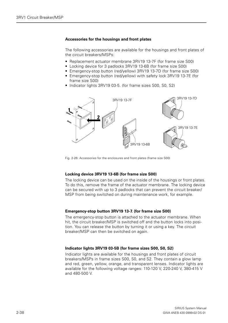
Accessories for the housings and front plates
The following accessories are available for the housings and front plates of the circuit breakers/MSPs:
• Replacement actuator membrane 3RV19 13-7F (for frame size S00)• Locking device for 3 padlocks 3RV19 13-6B (for frame size S00)• Emergency-stop button (red/yellow) 3RV19 13-7D (for frame size S00)• Emergency-stop button (red/yellow) with safety lock 3RV19 13-7E (for
frame size S00)• Indicator lights 3RV19 03-5. (for frame sizes S00, S0, S2)
Fig. 2-26: Accessories for the enclosures and front plates (frame size S00)
Locking device 3RV19 13-6B (for frame size S00)
The locking device can be used on the inside of the housings or front plates. To do this, remove the frame of the actuator membrane. The locking device can be secured with up to 3 padlocks that can prevent the circuit breaker/MSP from being switched on during maintenance work, for example.
Emergency-stop button 3RV19 13-7. (for frame size S00)
The emergency-stop button is attached to the actuator membrane. When hit, the circuit breaker/MSP is switched off and the button locks into posi-tion. You can release the button by turning it or using a key. The circuit breaker/MSP can then be switched on again.
Indicator lights 3RV19 03-5B (for frame sizes S00, S0, S2)
Indicator lights are available for the housings and front plates of circuit breakers/MSPs in frame sizes S00, S0, and S2. They contain a glow lamp and red, green, yellow, orange, and transparent lenses. Indicator lights are available for the following voltage ranges: 110-120 V, 220-240 V, 380-415 V and 480-500 V.
3RV19 13-6B
3RV19 13-7D
3RV19 13-7E
12
3RV19 13-7F
SIRIUS System Manual2-38 GWA 4NEB 430 0999-02 DS 01

3RV1 Circuit Breaker/MSP
Installation of the indi-
cator lights
There is a precut opening on the front of the housing that can be knocked out to install an indicator light
Fig. 2-27: Indicator light installation in a molded-plastic housing (example: frame size S00)
2
116 mm
3RV19 03-5.
SIRIUS System ManualGWA 4NEB 430 0999-02 DS 01 2-39

3RV1 Circuit Breaker/MSP
2.4.8 Busbar adapter 8US1 (Fastbus system)
To enable the circuit breakers/MSPs to be mounted without using up too much space, and to ensure that the infeed is economical in terms of both time and money, the switches can be mounted directly onto busbar systems using busbar adapters.
The circuit breakers/MSPs are snapped onto the adapter and connected at the input side. This prepared unit is mounted directly onto the busbar sys-tems, thus both attaching it mechanically and establishing electrical contact.
Busbar systems The adapters are suitable for the following systems:
Accessories The following accessories are available for busbar adapters:
• Modules that can be mounted on either side to widen the adapters• Busbar holder for 3 rails• Molded-plastic covers for 3 terminals (40 mm system)• Molded-plastic cover profiles for shock protection
Measurements The following table lists the dimensions of the busbar adapters and accesso-ries.
1) Up to 460 V AC with max. short-circuit breaking capacity of 25 kA2) Not to be used for voltages < 480 Vshort-circuit breaking capacity 480/500/525 V AC- Up to In=25 A: max. 30 kA- Up to In=90 A: max. 16 kAshort-circuit breaking capacity 690 V AC: max. 12 kA
Busbar systems with
center-to-center spacing
For copper busbars in acc. with DIN 46 433
Width Depth
40 mm systems 12 mm and 15 mm 5 mm and 10 mm
60 mm systems 12 mm to 30 mm 5 mm and 10 mm
Table 2-14: Busbar systems
SystemBusbar adapter and
accessoriesLength Width
For circuit
breakers/MSPs in
frame size
40 mm Circuit breaker/MSP+ lateral auxiliary switch
121 mm121 mm
45 mm 55 mm
S00, S0 S00, S0
Circuit breaker/MSP 139 mm 55 mm S2
Circuit breaker/MSP 182 mm182 mm
70 mm72 mm
S3 (to 400 V)1)
S3 (480 to 690 V)2)
Side module 139 mm182 mm
13.5 mm 13.5 mm
S2 S3
60 mm Circuit breaker/MSP 182 mm 45 mm S00, S0
182 mm 55 mm S2
182 mm182 mm
70 mm72 mm
S3 (to 400 V)1)
S3 (480 to 690 V)2)
Side module 182 mm 13.5 mm S00 to S3
Table 2-15: Dimensions of the busbar adapters and accessories
SIRIUS System Manual2-40 GWA 4NEB 430 0999-02 DS 01
3RV1 Circuit Breaker/MSP
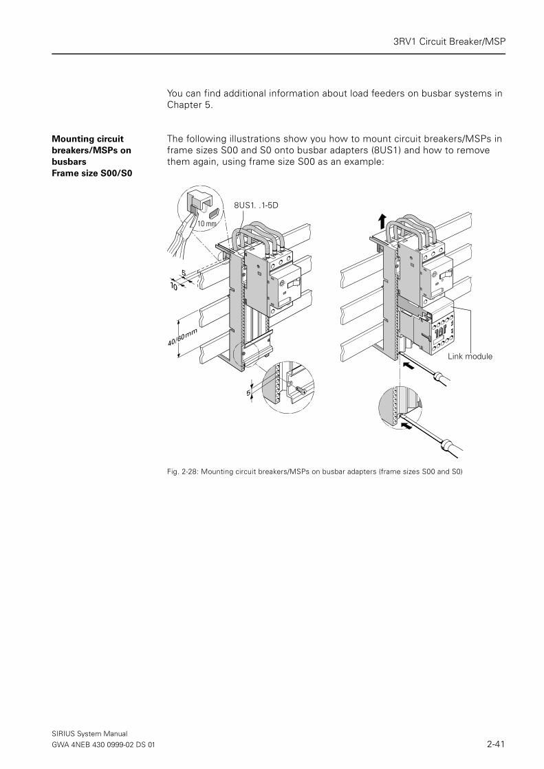
You can find additional information about load feeders on busbar systems in Chapter 5.
Mounting circuit
breakers/MSPs on
busbars
Frame size S00/S0
The following illustrations show you how to mount circuit breakers/MSPs in frame sizes S00 and S0 onto busbar adapters (8US1) and how to remove them again, using frame size S00 as an example:
Fig. 2-28: Mounting circuit breakers/MSPs on busbar adapters (frame sizes S00 and S0)
10 mm
8US1. .1-5D
Link module
SIRIUS System ManualGWA 4NEB 430 0999-02 DS 01 2-41
3RV1 Circuit Breaker/MSP
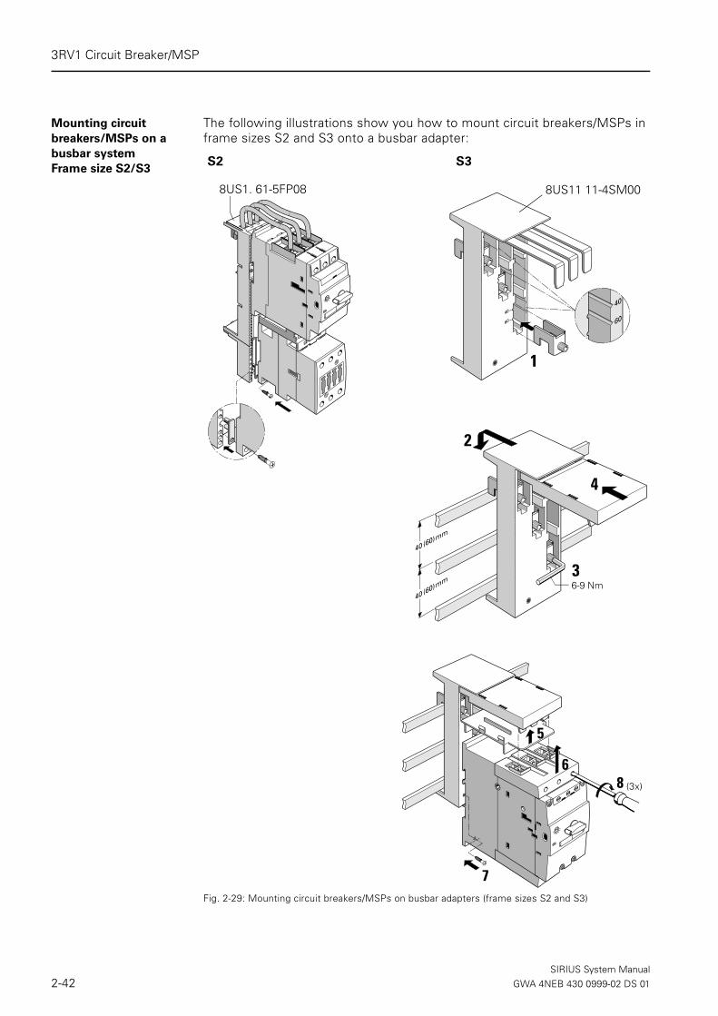
Mounting circuit
breakers/MSPs on a
busbar system
Frame size S2/S3
The following illustrations show you how to mount circuit breakers/MSPs in frame sizes S2 and S3 onto a busbar adapter:
Fig. 2-29: Mounting circuit breakers/MSPs on busbar adapters (frame sizes S2 and S3)
S2
8US1. 61-5FP08
1
8US11 11-4SM00
6-9 Nm
2
3
4
8
5
7
6
S3
(3x)
SIRIUS System Manual2-42 GWA 4NEB 430 0999-02 DS 01
3RV1 Circuit Breaker/MSP
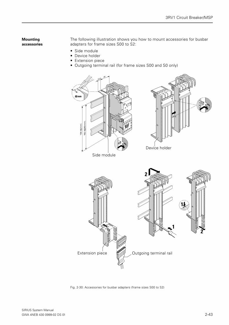
Mounting
accessories
The following illustration shows you how to mount accessories for busbar adapters for frame sizes S00 to S2:
• Side module • Device holder• Extension piece • Outgoing terminal rail (for frame sizes S00 and S0 only)
Fig. 2-30: Accessories for busbar adapters (frame sizes S00 to S2)
Outgoing terminal railExtension piece
40 mm
1
2
1
2
Side module
Device holder
SIRIUS System ManualGWA 4NEB 430 0999-02 DS 01 2-43

3RV1 Circuit Breaker/MSP
2.4.9 Isolated 3-phase busbar system
For 3RV1 frame sizes S00, S0, and S2, 3-phase busbars can be used to quickly and easily provide line side feeding when mounting circuit breakers/MSPs on to DIN rail. There is only one power supply, via a feed-in terminal.
The 3-phase busbar systems are safe from fingers and are shock protected DIN VDE 0106 Teil 100. They are rated for the short-circuit stress that can occur on the output side of the connected circuit breakers/MSPs.
Fig. 2-31: 3-phase busbar system (example: Frame size S00)
Rated operational
voltage/current
Versions The 3-phase busbars take 2 to 5 circuit breakers/MSPs, depending on the model. There are busbars with more generous spacing for circuit breakers/MSPs with accessories attached on the side
3-phase busbar 3RV19 15-1CB
Protective cap 3RV19 15-6AB
Feeder lugs, connecton from below 3RV19 15-5B
Feeder lugs, connecton from above (3RV1915-5A))
Spacer
Rated operational voltage 690 V
Rated current Frame sizes S00, S0: 63 A
Frame size S2: 108 A
Table 2-16: Rated operational voltage/current
Frame size
of the
circuit
breaker/
MSP
Spacing Models
S00, S0 45 mm For 2, 3, 4, or 5 circuit breakers/MSPs
55 mm For 2, 3, 4, or 5 circuit breakers/MSP + acc.
63 mm For 2 or 4 circuit breakers/MSPs + accessories
S2 55 mm For 2, 3, or 4 circuit breakers/MSPs
75 mm For 2, 3, or 4 circuit breakers/MSPs + accesso-ries
Table 2-17: Types of 3-phase busbars
SIRIUS System Manual2-44 GWA 4NEB 430 0999-02 DS 01

3RV1 Circuit Breaker/MSP
Combination of
frame sizes S00
and S0
Circuit breakers/MSPs in frame sizes S00 and S0 vary in height and depth. They therefore cannot be combined on one busbar. You can combine two busbars for circuit breakers/MSPs in frame sizes S0 and S00 using an exten-sion piece.
Extending the bus It is possible to extend the busbars by clamping the connecting lugs of a another bus (turned 180°) under the terminals of the last circuit breaker/MSP (see the section on mounting).
Attention
Note the current-carrying capacity of the busbars when you extend them.
Accessories The following accessories are available for the isolated 3-phase busbar sys-tem:
• Feeder lugs from above (3RV1915-5A for S00, 3RV1925-5AB for S0, 3RV1935-5A for S2)
• Feeder lugs from below (3RV1915-5B for S00, S0)• Connector
A connector links two 3-phase busbars over a space of 45 mm for circuit breakers/MSPs in frame size S0 (left) and frame size S00 (right).
• Protective cap for connecting lugs (3RV19 15-6AB)Protective caps provide shock protection for spare slots. To extend the bus, remove the protective caps.
Feeder lugs 3-phase feeder lugs make it possible to have greater conductor cross-sec-tions than on the circuit breaker/MSP itself. Tightening torque: 2 to 4 Nm (17.6 to 35.2 lb·in).
Feeder lugs- connec-
tion from below
Attention
The feeder lugs with connection from below is clamped on instead of a cir-cuit breaker/MSP. Make sure you check how much space you require when planning the 3-phase busbars.
Frame size of
the circuit
breaker/MSP
Connec-
tionConductors
Conductor
cross-section
S00, S0 From above Single- or multi-coreFinely stranded with wire end
ferruleAWG
2.5 to 25 mm2
2.5 to 25 mm2
12 to 4
S00, S0 From below Single- or multi-coreFinely stranded with wire end
ferruleAWG
6 to 25 mm2
4 to 16 mm2
10 to 4
S2 From above Single- or multi-coreFinely stranded with wire end
ferruleAWG
2.5 to 50 mm2
1.5 to 35 mm2
14 to 0
Table 2-18: Conductor cross sections of the 3 phase feeder lugs
SIRIUS System ManualGWA 4NEB 430 0999-02 DS 01 2-45

3RV1 Circuit Breaker/MSP
Mounting the 3-phase
busbars
Fig. 2-32: Mounting the isolated 3-phase busbar system (frame sizes S00 to S0)
Frame size S0
Screw connection
Frame size S00
Cage-clamp
Frame size S00
Screw connection Turned 180°
3RV19 15-5B
3RV19 15-6AB
3RV19 15-1CB
3b3a
3c
3
1
1
2
3RV19 25-5AB
3RV19 15-5B
3RV19 15-6AB
3RV19 15-1CB
8WA20 11-1DG30
Turned 180°
3RV19 15-5A
3RV19 15-1CA
SIRIUS System Manual2-46 GWA 4NEB 430 0999-02 DS 01

3RV1 Circuit Breaker/MSP
Fig. 2-33: Mounting the isolated 3-phase busbar system (frame size S2)
2.4.10 Link module for connection to a contactor
Link Module
Circuit breaker/MSP-
Contactor
When assembling a combination starter (load feeder) a link module between the circuit breaker/MSP and the contactor is needed to provide both an elec-trical and mechanical connection. The following types of link modules are available:
Frame size S2
Screw connection
3RV19 35-5A
3RV19 35-6A
3RV19 35-1.
3RV19 35-1C
Operating voltage
Contactor
Frame size
Contactor
Frame size
Circuit breaker/MSP
AC and DC S00 S00
S00 S0
S0 S0
S2 S2
S3 S3
Table 2-19: Link module circuit breaker/MSP-contactor
SIRIUS System ManualGWA 4NEB 430 0999-02 DS 01 2-47

Circuit Breaker/MSP 3RV1
2.5 Mounting and connection
2.5.1 Installation
Mounting position You can install the 3RV1 circuit breakers/MSPs in almost any position.
Snap-on mounting The circuit breakers/MSPs are mounted by snapping them onto 35 mm rails that comply with DIN EN 50 022. The circuit breakers/MSPs with a frame size of S3 require a rail with an installation height of 15 mm. Alternatively, they can also be snapped onto 75 mm rails.
Fig. 2-34: Mounting the circuit breakers/MSPs onto the rail
Panel mounting The circuit breakers/MSPs can be attached to a flat surface with 2 screws. For circuit breakers/MSPs in frame sizes S00 and S0, two push-in lugs (3RB1900-0B) (pack of 10) are also required. Circuit breakers/MSPs in frame sizes S2 and S3 can be screwed directly onto a base plate.
Fig. 2-35: Screw-on mounting of the 3RV1 (example: frame size S00)
S00
RV-0
0298
1
2
11
2
DIN EN 50022/23S3
DIN EN 50022
RV-0
0226
3RB19 00-0B
SIRIUS System Manual2-48 GWA 4NEB 430 0999-02 DS 01
Circuit Breaker/MSP 3RV1
2.5.2 Connection
Tools The following items are required to connect the circuit breakers/MSPs:• Frame sizes S00 to S2: Pozidriv 2 screwdriver• Frame size S3: Allen key (4 mm)
Conductor cross-sec-
tions
The typical SIRIUS conductor cross-sections apply (see Section 1.5.2 "Con-ductor cross-sections").
Screw-type terminals 3RV1 circuit breakers/MSPs with frame sizes S00 and S0 have terminals with captive screws and terminal washers that enable you to connect 2 conductors, even if they have different cross-sections.
The box terminals of the circuit breakers/MSPs of frame sizes S2 and S3 can also take 2 conductors with different cross-sections. With the exception of circuit breakers/MSPs of frame size S3, which have terminal screws with a 4 mm Allen screw, all the terminal screws can be tightened using a standard screwdriver or a Pozidriv screwdriver (size 2).
You can remove the box terminals from circuit breakers/MSPs with a frame size of S3 to connect conductors with ring-tongue or connecting bars. A ter-minal cover is available as shock protection and to ensure that you comply with the required creepages and clearances when the box terminals are removed.
Soldering pin connec-
tor
Circuit breakers/MSPs in frame size S00 can be soldered onto printed circuit boards by means of a soldering pin connector. A soldering pin connector is available for the main contacts only (3RV19 18-5A) or for the main contacts and the transverse auxiliary contacts 1NO +1NC (3RV19 18-5B).
SIRIUS System ManualGWA 4NEB 430 0999-02 DS 01 2-49

Circuit Breaker/MSP 3RV1
Mounting the solder-
ing pin adapters
The soldering pin adapters are clamped above and below in the screw-type terminals of the circuit breakers/MSPs. The power supply can also be taken to the printed circuit boards via cables.
Fig. 2-36: Circuit breaker/MSP, soldering pin connector (frame size S00)
1
1
1
1
2
4
3
2
SIRIUS System Manual2-50 GWA 4NEB 430 0999-02 DS 01

Circuit Breaker/MSP 3RV1
2.5.3 Device circuit diagrams
Frame size S00
Fig. 2-37: Device circuit diagram (frame size S00, example: Circuit breaker (MSP) for motor protection 3RV10)
Frame size S0 to S3
Fig. 2-38: Device circuit diagram (frame size S00, example: Circuit breaker (MSP) for motor protection 3RV10)
max. 10 A
31 L3L2L1
642 T3T2T1
5
11
14 12
3RV1901-1DU
D2
D13RV1902-.A..
U
D1
D2 08
07
3RV1912-.C..
14
13 21
22
3RV1901-.EC2
C13RV1902-.D..
I >> I >>I >>
3RV1901-1G
33 41
34 42
3RV1901-.A4333
4434
3RV1901-.B
4232
4131
3RV1901-.C3RV1901-.J13 21 31 43
1422 32 44
2313
2414
3RV1901-1F
34
33 41
42
3RV1901-.A4333
4434
3RV1901-.B
4232
4131
3RV1901-.C
max. 10 A
31 L3L2L1
642 T3T2T1
5
11
14 12
3RV1901-1D UD2
D13RV1902-.A..
U
D1
D2 08
073RV1922-.C..
14
13 21
22
3RV1901-.EC2
C13RV1902-.D..
I >> I >>I >>
78
77 85
86
58
57 65
66
3RV1921-1M
3RV1901-1G
3RV1901-.J13 21 31 43
14 22 32 44
3RV1901-1F
2313
2414
SIRIUS System ManualGWA 4NEB 430 0999-02 DS 01 2-51

Circuit Breaker/MSP 3RV1
Circuit breaker/MSP
with overload relay
function
Frame size S0 to S3
Fig. 2-39: Circuit breaker/MSP with overload relay function, device circuit diagrams (frame sizes S0 to S3)
max. 10 A
31 L3L2L1
642 T3T2T1
5
I >> I >>I >>
98
97 95
96
34
33 41
42
3RV1901-.A4333
4434
3RV1901-.B
4232
41313RV1901-.C3RV1901-.J
13 21 31 43
14 22 32 44
11
14 12
3RV1901-1D
14
13 21
22
3RV1901-.E
3RV1901-1F
2313
2414
3RV1901-1G
SIRIUS System Manual2-52 GWA 4NEB 430 0999-02 DS 01
Circuit Breaker/MSP 3RV1
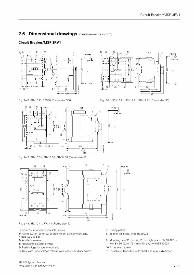
2.6 Dimensional drawings (measurements in mm)
Circuit Breaker/MSP 3RV1
Fig. 2-42: 3RV10 31, 3RV13 31, 3RV14 31 (Frame size S2)
Fig. 2-43: 3RV10 4, 3RV13 4 (Frame size S3)
Fig. 2-40: 3RV10 11, 3RV16 (Frame size S00) Fig. 2-41: 3RV10 21, 3RV13 21, 3RV14 21 (Frame size S0)
1) side-mount auxiliary contacts, 2-pole 7) Drilling pattern2) Alarm switch (S0 to S3) or side-mount auxiliary contacts, (4-pole S00 to S3)
8) 35 mm rail in acc. with EN 50022
3) Auxiliary release 9) Mounting onto 35 mm rail, 15 mm high, in acc. EN 50 022 or with EN 50 022 or 75 mm rail in acc. with EN 500234) Transverse auxiliary switch
5) Push-in lugs for screw mounting 10)4 mm Allen screw6) Only with undervoltage release with leading auxiliary switch 11)Lockable in 0 position with shackle (5 mm in diameter
1) 11) 3) 4)5)
8)N
SB 0
0026
c45
90
7076
9 18625
4512
453,
5
6)
2)
18
25
5
105
7)
11)2) 5) 4)
8)
3)1)
NSB
0002
7b
45
14
1290 97
45 5 56
8091
45
6918 18
72
9
5
25
106
7)
20
5518 18
45 85
109
121
1275
8
132144
140
89125
1) 2)
3) 4)
8)
NSB
0002
8a
11)
9
5
3013
0
7)
45
7018 18
116
165
150
5
7
8
132153157
14610)11)
1) 2)3)
4)
9)
NSB
0002
9b
169
9
5
30
155
7)
SIRIUS System ManualGWA 4NEB 430 0999-02 DS 01 2-53

Circuit Breaker/MSP 3RV1
3RV11 circuit breaker/MSP with overload relay function
Fig. 2-46: 3RV11 42 (Frame size S3)
1) Side-mount auxiliary contacts, 2-pole2) Alarm switch (S0 to S3) or side-mount auxiliary contacts, 4-pole (S00 to S33) Block for overload relay function4) Transverse auxiliary switch5) Push-in lugs for screw-type mounting6) Drilling pattern7) 35 mm rail in acc. with EN 50 0228) Mounting onto 35 mm rails, 15 mm high, in acc. with EN 50 022 or 75 mm rails in acc. with EN 50 0239) 4 mm Allen screw10)Lockable in 0 position with shackle (5 mm in diameter)
Fig. 2-44: 3RV11 21, 3RV16 (Frame size S0) Fig. 2-45: 3RV11 (Frame size S2)
45
451290 97
5 55
8091
45
6920
72 4)
7)
11) 5) 3)2)1)
NSB
0003
0b
189
5
25
106
6)
55
20
20
45 90 140
109
121
1275 8
132144
125
3)
4)
7)
11)
NSB
0003
1c
2)1)
189
5
30
130
6)
70
90
20
45 116
150
57
8146
132153
157
165
9) 3) 4)
8)
10)
NSB
0003
2c
2)1)
169
189
5
30
155
6)
Fig. 2-47: 3RV19 28-1A (for Frame size S0) Fig. 2-48: 3RV19 38-1A (for Frame size S2)
51
9445
NSB
0003
3a 9614
4
55
NSB
0003
4a
149
5712
119
0
Disconnecting/isolator module
SIRIUS System Manual2-54 GWA 4NEB 430 0999-02 DS 01

Circuit Breaker/MSP 3RV1
Molded-plastic panel/surface mount enclosure
Fig. 2-49: 3RV19 13-1.... (for Frame size S00)
a) 3RV19 13-1CA00: 85 mm 3RV19 13-1DA00: 105 mm
1) Knockout opening for M252) Knockout opening for rear M20 cable routing
b) with 3RV19 13-7D: 146.5 mm with 3RV19 13-7E: 166.5 mm The dimensions relate to the mounting surface
3) With safety lock4) Max. shackle diameter for padlock is 8 mm5) Indicator light 3RV19 03-5.
c) with 3RV19 13-7D: 64 mm with 3RV19 13-7E: 84 mm
6) Locking device 3RV19 13-6B7) Emergency-stop button 3RV19 13-7
d) The dimensions relate to the mounting surface
NS
B 0
0035
c
a)
77,5
45 19
145
- 148
4,5
88
7)
b) 99b) 100,5
b) 143d) 190
b)
c)10555
13115)
1)2)
4)
6)
3)
Fig. 2-50: 3RV19 23-1.... (for Frame size S0) Fig. 2-51: 3RV19 33-1.... (for Frame size S2)
a) 3RV19 23-1CA00: 85 mm 3RV19 23-1DA00: 105 mm
1) Knockout opening for M32 (left) and M40 (right2) Knockout opening for rear M32 cable entry
1) Knockout opening for M25 3) Opening for padlock with a max. shackle diameter of 8 mm2) Knockout opening for rear M20 cable entry 4) Indicator light 3RV19 03-5.3) Opening for padlock with a max. shackle diameter of 8 mm4) Indicator light 3RV19 03-5.
15018
181
235
250
7252932
3)
NSB
000
37c
1) 2)
4)1945
2)
145
- 148
4,5
155
a) 12618
NS
B 0
0036
c
3)
1)4)
SIRIUS System ManualGWA 4NEB 430 0999-02 DS 01 2-55

Circuit Breaker/MSP 3RV1
Cast-Aluminum panel/surface mount enclosure
Fig. 2-52: 3RV19 23-1.A01 for circuit breaker/MSP Frame size S0
Molded-plastic flush mount enclosure
Molded-plastic-Front plate
Fig. 2-55: 3RV19 13-4C (Frame size S00)
160
170
135
52
116105
1)2)
2)
NSB
010
88a
ONI
O
OFF
O
M 25
M 25
2)
1) Leuchtmelder 3RV19 03-5.2) Ausbrechöffnungen für Verschraubung M25
1) Indicator light2) Knockout opening for M25
Fig. 2-53: 3RV19 13-2DA00 (Frame size S00) Fig. 2-54: 3RV19 23-2DA00/-2GA00 (Frame size S0)
105
1)max. 7
12 87
2)3)
95
1) Leuchtmelder 3RV19 03-5.2) Ausbrechöffnungen für M253) Ausbrechöffnungen für M20
105 95
max. 6
12 87
1)2)3)
1) Leuchtmelder 3RV19 03-5.2) Ausbrechöffnungen für M253) Ausbrechöffnungen für M20
1) Indicator light 3RV1903-52) Knockout opening for M253) Knockout opening for M20
1) Indicator light 3RV1903-52) Knockout opening for M253) Knockout opening for M20
40
NSB 00039a
85 56,5 10
12
6270
4,5ø 71)
1) Leuchtmelder 3RV19 03-5.1) Indicator light 3RV1903-5
SIRIUS System Manual2-56 GWA 4NEB 430 0999-02 DS 01

Circuit Breaker/MSP 3RV1
Molded-plastic Front plate and Support
Fig. 2-56: 3RV19 23-4B, 3RV19 23-4E (Frame size S0, S2, S3); 3RV19 23-4G (only for Frame size S0)
Soldering pin adapters for main and auxiliary contacts
Fig. 2-57: 3RV19 18-5A/-5B (Frame size S00)
40
NSB 00042a
85 56,5 10
1812
6270
7,4ø 3,51)
1) Leuchtmelder 3RV19 03-5. 1) Indicator light 3RV1903-5
45
NS
B00
041
13,412
13,1
5
8,4
14,4 14,4
8,4
14,414,4
97,4
9
103
9
59
49
5
2
SIRIUS System ManualGWA 4NEB 430 0999-02 DS 01 2-57

Circuit Breaker/MSP 3RV1
Thru-the-door rotary operators
Fig. 2-58: 3RV19 26-0. (short shaft for circuit breaker/MSP frame sizes S0, S2, S3)
Fig. 2-59: 3RV19 26-0. (Long shaft (with support) for circuit breaker/MSP Frame sizes S0, S2, S3)
NS
B 0
1089
b
min. 55
2)
1)
5
4566
19 151 ... 4
1733max. 327
34,5
1) Abschließbar in Nullstellung mit Bügeldurchmesser max. 8 mm2) Befestigung mit Überwurfmutter
NS
B011
07
3
22,5
24,3
4)
min. 45max. 130
4) Lieferzustand mit Wellenlänge von 130 mm durch Kürzen der Welle anpassbar
1)Lockable in 0 position with shackle (max. 8 mm in diameter)2)Affixed with screw caps
3) Supplied with a shaft length of 130 mm: adaptable by shortening of the shaft
NS
B 01
090b
16
5) min. 55
2)
1)
5
4566
19 151 ... 4
1733max. 327
34,5
5) Erdungsklemme 35 mm2 und Haltewinkel für 330 mm Welle
1) Abschließbar in Nullstellung mit Bügeldurchmesser max. 8 mm2) Befestigung mit Überwurfmutter
NS
B011
08
3)
min. 45
3
22,5
24,3
max. 330
3) Lieferzustand mit Wellenlänge von 330 mm durch Kürzen der Welle anpassbar3) Supplied with a shaft length of 330 mm: adaptable by shortening of the shaft
1)Lockable in 0 position with shackle (max. 8 mm in diameter)2)Affixed with screw caps5) Ground terminal 35 mm2 and support bracket for 330 mm shaft
SIRIUS System Manual2-58 GWA 4NEB 430 0999-02 DS 01

Circuit Breaker/MSP 3RV1
Thru-the-door rotary operators for harsh conditions
Fig. 2-60: 3RV19 .6-2. (Frame sizes S0, S2, S3)
min. 11 mm without shaft
NSB01091a
E Fmax. 341min. 42
62 14
6
A 75
G
D
max. 330min. 31
40
65 B
J
CH
6
Type FrameSize
Measurements
Drilling pattern GroundDrilling pattern Door
A
125170194
B
111144180
C
506060
D
7787
100
E
112162187
F
505048
G
272725
H
91010
J
424753
S0S2S3
3RV1926-23RV1936-23RV1946-2
SIRIUS System ManualGWA 4NEB 430 0999-02 DS 01 2-59

Circuit Breaker/MSP 3RV1
Terminals for "Combination Motor Controller Type E" in acc. with UL 508
Motorized remote-control mechanism
Fig. 2-63: 3RV19 .6-3AP0 for circuit breaker/MSP a) 3RV19 36-3AP0, Frame size S2, 211 mmb) 3RV19 46-3AP0, Frame size S3, 236 mm
Fig. 2-61: 3RV19 28-1H (Frame size S0) Fig. 2-62: 3RT19 46-4GA07 (Frame size S3)
2772
121
7445
NSB 01228
10
NSB 01229
168
70
84
NSB
0004
4
RESET I>
AUTOMATIC REVISION
MANUAL
I
SI EMENS
∅5
87
182
224
148
112
a)
SIRIUS System Manual2-60 GWA 4NEB 430 0999-02 DS 01
Circuit Breaker/MSP 3RV1
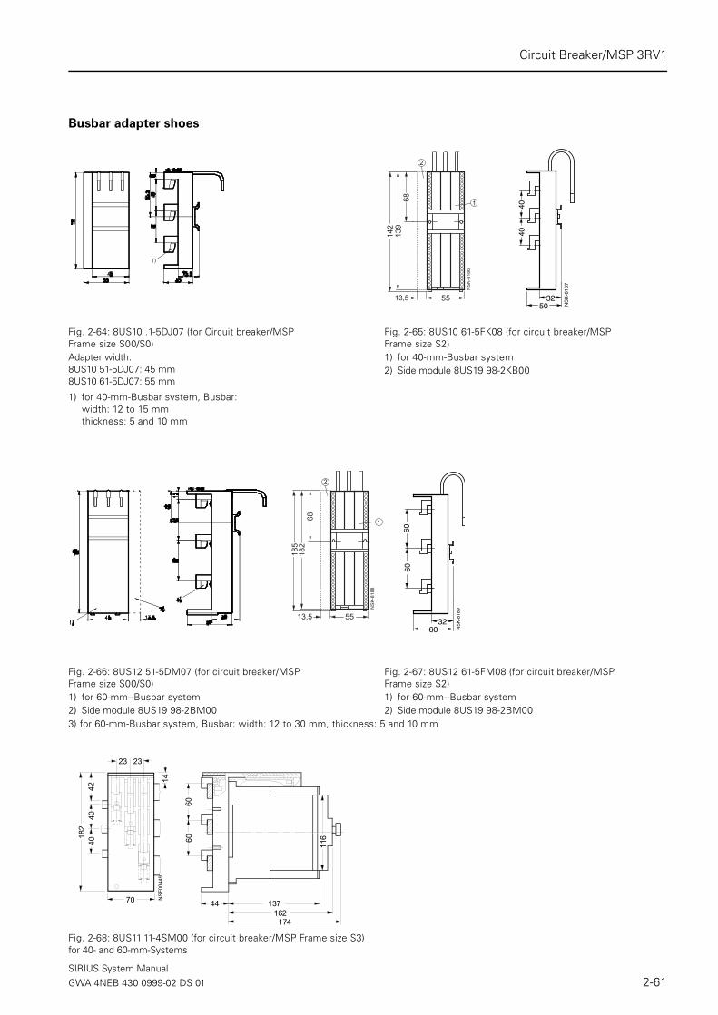
Busbar adapter shoes
Fig. 2-68: 8US11 11-4SM00 (for circuit breaker/MSP Frame size S3)for 40- and 60-mm-Systems
Fig. 2-64: 8US10 .1-5DJ07 (for Circuit breaker/MSP Frame size S00/S0)
Fig. 2-65: 8US10 61-5FK08 (for circuit breaker/MSPFrame size S2)
Adapter width:8US10 51-5DJ07: 45 mm8US10 61-5DJ07: 55 mm
1) for 40-mm-Busbar system 2) Side module 8US19 98-2KB00
1) for 40-mm-Busbar system, Busbar:width: 12 to 15 mm thickness: 5 and 10 mm
��������
��
��
�
�
�
���
4040
NS
K-8
187
3250
1)
Fig. 2-66: 8US12 51-5DM07 (for circuit breaker/MSP Frame size S00/S0)
Fig. 2-67: 8US12 61-5FM08 (for circuit breaker/MSP Frame size S2)
1) for 60-mm--Busbar system 1) for 60-mm--Busbar system2) Side module 8US19 98-2BM00 2) Side module 8US19 98-2BM00
��������
�
���
��
�
�
��
NS
K-8
189
3260
6060
NS
E004
49
182
70
14
6060
137162
174
116
4240
40
23 23
44
3) for 60-mm-Busbar system, Busbar: width: 12 to 30 mm, thickness: 5 and 10 mm
SIRIUS System ManualGWA 4NEB 430 0999-02 DS 01 2-61

Circuit Breaker/MSP 3RV1
3-phase busbar systems
Fig. 2-71: 3RV19 15-3..
Separation distance 63 mm:3RV19 15-3AB for 2 circuit breakers/MSPs (length 101 mm)3RV19 15-3CB for 4 circuit breakers/MSPs (length 227 mm)
Fig. 2-72: 3RV19 35-1. (for circuit breaker/MSP Frame size S2)
Separation distance 55 mm:3RV19 35-1A for 2 circuit breakers/MSPs (length 111 mm) 3RV19 35-1B for 3 circuit breakers/MSPs (length 166 mm) 3RV19 35-1C for 4 circuit breakers/MSPs (length 221 mm)
Fig. 2-69: 3RV19 15-1... (Frame size S00) Fig. 2-70: 3RV19 15-1... (Frame size S0)Separation distance 45 mm: Separation distance 55 mm:3RV19 15-1AB for 2 circuit breakers/MSPs (length 83 mm) 3RV19 15-2AB for 2 circuit breakers/MSPs with accessories
(length 93 mm)3RV19 15-1BB for 3 circuit breakers/MSPs (length 128 mm) 3RV19 15-2BB for 3 circuit breakers/MSPs with accessories
(length 148 mm)3RV19 15-1CB for 4 circuit breakers/MSPs (length 173 mm) 3RV19 15-2CB for 4 circuit breakers/MSPs with accessories
(length 203 mm)3RV19 15-1DB for 5 circuit breakers/MSPs (length 218 mm) 3RV19 15-2DB for 5 circuit breakers/MSPs with accessories
(length 258 mm)
21
13
6410
883128
173218
45
NSB 00055b
21
13
6410
85593
148
NSB 00056b
258203
21
13
6410
863101
227
NSB 01092b
31
55111
221 NSB
0005
7b
165
15
9616
6
SIRIUS System Manual2-62 GWA 4NEB 430 0999-02 DS 01

Circuit Breaker/MSP 3RV1
Fig. 2-73: 3RV19 35-3. (for circuit breaker/MSP Frame size S2)
Separation distance 75 mm:3RV19 35-3A for 2 circuit breakers/MSPs with accessories (length 121 mm) 3RV19 35-3B for 3 circuit breakers/MSPs with accessories (length 196 mm) 3RV19 35-3C for 4 circuit breakers/MSPs with accessories (length 271 mm)
3-Phase feeder lugs
Connector
31
75
271
121
NSB
0005
8b
196
9616
6
15
Fig. 2-74: 3RV19 15-5A Fig. 2-75: 3RV19 15-5B Fig. 2-76: 3RV19 25-5ABConnection from above (for frame size S00)
Connection from below (Frame size S00/S0)
Connection from below (Frame size S0)
Fig. 2-77: 3RV19 35-5A Fig. 2-78: 3RV19 15-5DBConnection from above (for frame size S2) Frame size S0 (left and frame size S00 (right)
NS
B00
060b
31a
92
14 1444
73
a) 19 mm for 3RV1.1a) 23 mm for 3RV1.2
4414 14
2554
114
71
NS
B01
093a
NS
B00
059a
2444
25
34 NSB
0006
1b
112
9116
1
55
8142,5
NSB
000
62c
108
64
21
13
SIRIUS System ManualGWA 4NEB 430 0999-02 DS 01 2-63

Circuit Breaker/MSP 3RV1
2.7 Technical specifications
2.7.1 General specifications
Type 3RV1. 1 3RV1. 2 3RV1. 3 3RV1. 4
Specifications
• IEC 60 947-1, EN 60 947-1 (VDE 0660 Part 100) Yes
• IEC 60 947-2, EN 60 947-2 (VDE 0660 Part 101) Yes
• IEC 60 947-4-1, EN 60 947-4-1 (VDE 0660 Part 102) Yes
Frame size S00 S0 S2 S3
Pole number 3
Max. rated current Inmax (= max. rated operational current Ie) A 12 25 50 100
Permissible ambient temperature
Storage/transportation °C -50 to +80
Operation °C -20 to +70 1)
Permissible rated current with the following internal cubicle temperature:
• +60 °C % 100
• +70 °C % 87
Circuit breaker in housing
Permissible rated current with the following ambient housing temperature:
• +35 °C % 100
• +60 °C % 87
Rated operational voltage Ue V 690 2)
Rated frequency Hz 50/60
Rated insulation voltage Ui V 690
Rated impulse strength Uimp kV 6
Utilization category
• IEC 60 947-2 (circuit breaker) A
• IEC 60 947-4-1 (motor starter) AC-3
CLASS In acc. with IEC 60 947-4-1 10 10 10/20 10/20
Direct current short-circuit breaking capacity (time constant τ = 5 ms)(time constant t = 5 ms)
• 1 conducting path 150 VDC kA 10
• 2 conducting paths in series 300 VDC kA 10
• 3 conducting paths in series 450 VDC kA 10
Power loss (Pv) per circuit breaker In -> to 1.25 A W 5 — — —
Depends on rated current In In -> 1.6 A to 6.3 A W 6 — — —
(Upper setting range) In -> 8 A to 12 A W 7 — — —
In -> to 0.63 A W — 5 — —
Rper conducting path = P/I2 × 3 In -> 0.8 A to 6.3 A W — 6 — —
In -> 8 A to 16 A W — 7 — —
In -> 20 A to 25 A W — 8 — —
In -> to 25 A W — — 12 —
In -> 32 A W — — 15 —
In -> 40 A to 50 A W — — 20 —
In -> to 63 A W — — — 20
In -> 75 A and 90 A W — — — 30
In -> to 100 A W — — — 38
SIRIUS System Manual2-64 GWA 4NEB 430 0999-02 DS 01

Circuit Breaker/MSP 3RV1
Type 3RV1. 1 3RV1. 2 3RV1. 3 3RV1. 4
Shock resistance In acc. with IEC 68 Part 2-27 g/ms 25/11 (rectangular and sine pulse)
Degree of protection In acc. with IEC 60 529 IP20 IP20 3)
Shock protection In acc. with DIN VDE 0106 Part 100
protected against touching by fingers
Temperature compensation In acc. with IEC 60 947-4-1 °C -20 to +60
Phase loss sensitivity In acc. with IEC 60 947-4-1 Yes
Explosion protection In acc. with DIN VDE 0165 and EN 50 019 Yes for 3RV10 (Class 10), 3RV11(Class 10)
Isolating function In acc. with IEC 60 947-2 Yes
Main and emergency-stop switch features4) In acc. with IEC 60 204-1 (VDE 0113)
Yes
Safe isolation between the main circuit and the
auxiliary circuit required for PELV applications
In acc. with DIN VDE 0106 Part 101
• to 400 V + 10 % Yes
• to 415 V+ 5 % (higher voltage on request) Yes
Mechanical life Operating cycles
100,000 50,000
Electrical life 100,000 25,000
Max. switching frequency per hour (motor star-
tups)
1/h 15
1) Reduction in current above +60 °C 3) Connection room IP002) With molded-plastic housing 500 V 4) With corresponding accessories
SIRIUS System ManualGWA 4NEB 430 0999-02 DS 01 2-65

Circuit Breaker/MSP 3RV1
Conductor cross-sections - main circuit
1) After the box terminals have been removed, lug or busbar connections are also possible.2) For notes on the Cage Clamp system, see pages 1-19. 3) Use an insulation stop for a conductor cross-section ≤ 1 mm2.4) Associated opening tool 8WA28 03/8WA28 04
Type 3RV1. 3RV1. 2 3RV1. 3 3RV1. 4
Connection type Screw-type terminal Screw-type terminal with box termi-nal
Terminal screw Pozidriv size 2 Pozidriv size 2 Allen screw 4 mm
Specified tightening torque Nm 0.8 to 1.2 Nm 2 to 2.5 3 to 4.5 4 to 6
Conductor cross-sections, 1 or 2 conductors
Single-core mm² 2 x (0.5 to 1.5) 2 x (1 to 2.5) 2 x (0.75 to 16) 2 x (2.5 to 16)
mm² 2 x (0.75 to 2.5)(max. 4)
2 x (2.5 to 6) - -
Finely stranded with wire end ferrule: mm² 2 x (0.5 to 1.5) 2 x (1 to 2.5) 2 x (0.75 to 16) 2 x (2.5 to 35)
mm² 2 x (0.75 to 2.5) 2 x (2.5 to 6)(max. 10)
1 x (0.75 to 25) 1 x (2.5 to 50)
Stranded mm² 2 x (0.5 to 1.5) 2 x (1 to 2.5) 2 x (0.75 to 25) 2 x (10 to 50)
mm² 2 x (0.75 to 2.5)(max. 4)
2 x (2.5 to 6)(max. 10)
1 x (0.75 to 35) 1 x (10 to 70)
AWG cables, single- or multi-core AWG 2 x (18 to 14) 2 x (14 to 10) 2 x (18 to 3) 2 x (10 to 1/0)
AWG - - 1 x (18 to 2) 1 x (10 to 2/0)
Ribbon cables (number x width x depth) mm - - 2 x (6 x 9 x 0.8) 2 x (6 x 9 x 0.8)
Removable box terminal 1)
With copper busbars mm - - - 18 x 10
With lug mm² - - - To 2 x 70
Cage Clamp connections2)3)4)(1 or 2 conn. can be connected) Single-coil
Finely stranded with wire end ferruleFinely stranded without wire end ferruleAWG cables, single-core or stranded
mm²mm²mm²AWG
2 x (0.25 to 2.5)2 x (0.25 to 1.5)2 x (0.25 to 2.5)2 x (24 to 14)
----
Max. outer diameter of the conductor insulation: 3.6 mm
Permissible service position AnyIn acc. with IEC 60 447 start com-mand "I"Right or above
Auxiliary contacts
Front transverse auxiliary contacts with 1 changeover contact Switching capacity with different voltages
Rated operational voltage Ue AC voltage VAC 24 230 400 690
Rated operational current Ie/AC-15 A 4 3 1.5 0.5
Rated operational current Ie/AC-12 Ith A 10 10 10 10
Rated operational voltage Ue DC voltage L/R 200 ms VDC 24 110 220
Rated operational current Ie/DC-13 A 1 0.22 0.1
Front transverse electronically optimized auxiliary contacts with 1 changeover contact
Rated operational voltage Ue AC voltage VAC 3 to 60
Rated operational current Ie/AC-14 mA 1 to 300
Rated operational voltage Ue DC voltage L/R 200 ms VDC 3 to 60
Rated operational current Ie/DC-13 mA 1 to 300
Front transverse auxiliary contacts with 1 NO + 1 NC, 2 NO contacts
Rated operational voltage Ue AC voltage VAC 24 230
Rated operational current Ie/AC-15 A 2 0.5
Rated operational current Ie/AC-12 Ith A 2.5 2.5
Rated operational voltage Ue DC voltage L/R 200 ms VDC 24 48 60
Rated operational current Ie/DC-13 A 1 0.3 0.15
Side-mount auxiliary contacts with 1 NO + 1 NC, 2 NO, 2 NC, 2 NO + 2 NC and alarm switch
Rated operational voltage Ue AC voltage VAC 24 230 400 690
Rated operational current Ie/AC-15 A 6 4 3 1
Rated operational current Ie/AC-12 Ith A 10 10 10 10
Rated operational voltage Ue DC voltage L/R 200 ms VDC 24 110 220 440
Rated operational current Ie A 2 0.5 0.25 0.1
SIRIUS System Manual2-66 GWA 4NEB 430 0999-02 DS 01

Circuit Breaker/MSP 3RV1
2.7.2 Permissible rating of approved devices for North America, u s
In North America the 3RV1 is not approved as a “circuit breaker” and is commonly known as a Motor Starter Protector (MSP). The SIRIUS 3RV1 series are approved for u/s and can also be used in acc. with UL 508 and C22.2 No.14 with a contactor as a Type F combi-nation starter. You can use these MSPs as a "Manual Motor Starter" for "Group Fusing" or for "Group Installation" or as a "Combination Motor Controller Type E".
3RV1 as a "Manual Motor Starter"
When the 3RV1 is used as a "Manual Motor Starter", it is always with a device for short-circuit protection (upstream short-circuit pro-tection device). Any fusible link (“group fusing”) or UL 489 listed circuit breaker (“group installation”) can be used as a device for short-circuit protection. The type and size are selected in acc. with the American NFPA 70 standard, Article 430-53 (c) for adequate protec-tion of supply wiring. Accreditation was issued under the following file numbers with the listed data: u File No. E47705, Product Class NLRVs Master Contract 165071, Product Class 3211 05
Motor Starter Protector Hp rating Rated current To 240 VAC To AC 480 Y/277 V To AC 600 Y/347 V
For FLA max. In Icu1) Icu
1) Icu1)
Type V 1-phase 3-phase A kA kA kA0.11 to 2 65 65 10
3RV10 11 2.5 65 65 103RV16 11-0BD10 115 ½ - 3.2 65 65 10
200 1½ 3 4 65 65 10Frame size S00 230 2 3 5 65 65 10
460 - 7½ 6.3 65 65 10FLA max. 12 A, 600 V 575/600 - 10 8 65 65 10
10 65 65 1012 65 65 100.11 to 3.2 65 65 30
3RV10 21/3RV11 21 4 65 65 303RV13 21 5 65 65 30
115 2 - 6.3 65 65 30Frame size S0 200 3 7½ 8 65 65 30
230 5 7½ 10 65 65 30FLA max. 25 A, 600 V 460 - 15 12.5 65 65 30
575/600 - 20 16 65 65 3020 65 65 3022 65 65 3025 65 65 30
3RV10 31/3RV11 31 11 to 16 65 50 253RV13 31 20 65 65 25
115 3 - 25 65 65 25Frame size S2 200 7½ 15 32 65 65 25
230 10 20 40 65 65 25FLA max. 50 A, 600 V 460 - 40 45 65 65 25
575/600 - 50 50 65 50 2511 to 16 65 65 30
3RV10 41/3RV10 42 20 65 65 303RV11 42 115 10 - 25 65 65 303RV13 41/3RV13 42 200 20 30 32 65 65 30
230 20 40 40 65 65 30Frame size S3 460 - 75 50 65 65 30
575/600 - 100 63 65 65 30FLA max. 99 A, 600 V 75 65 65 30
90 65 65 30100 (99) 65 65 30
Hp rating = output power in horse power (maximum motor power)FLA = full load amps
1) 1) Corresponds to "short circuit breaking capacity" in acc. with UL
SIRIUS System ManualGWA 4NEB 430 0999-02 DS 01 2-67

Circuit Breaker/MSP 3RV1
3RV10.A as "Combination Motor Controller Type E"
Since July 16th 2001, 1 inch air clearance and 2 inch creepage distance is required for a "Combination Motor Controller Type E" on the input side with UL 508 The 3RV10 in frame sizes S0 and S3 are therefore approved with the terminal blocks listed below in acc. with UL 508. The 3RV10 in frame size S2 already complies with the required air clearance and creepage distance as a basic unit. These extended air clearances and creepage distances are not required for CSA. The terminal blocks are therefore not required for use as a "Combination Motor Controller Type E" in acc. with CSA. 3RV10’s are certified as "Combination Motor Controller Type E" under the following file num-bers with the listed data: u File No. E156943, Product Class NKJHs Master Contract 165071, Product Class 3211 08
Hp rating = output power in horse power (maximum motor power)FLA = full load amps1) 1) Corresponds to "short circuit breaking capacity" in acc. with UL2) Not required by CSA
Motor Starter Protector Hp rating Rated current To 240 VAC To AC 480 Y/277 V To AC 600 Y/347 V
For FLA max. In Icu1) Icu
1) Icu1)
Type V 1-phase 3-phase A kA kA kA0.11 to 1.6 50 50 30
3RV10 21 2 50 50 30+ 3RV19 28-1H2) 115 2 — 2.5 50 50 30
200 3 7½ 3.2 50 50 30Frame size S0 230 3 7½ 4 50 50 30
460 — 15 5 50 50 30FLA max. 22 A, 480 V 575/600 — 10 6.3 50 50 30
12.5 A, 600 V 8 50 50 3010 50 50 3012.5 50 50 3016 50 50 —20 50 50 —22 50 50 —11 to 16 50 50 25
3RV10 31 20 50 50 25115 3 — 25 50 50 25
Frame size S2 200 7½ 15 32 50 50 25230 10 20 40 50 50 25
FLA max. 50 A, 600 V 460 — 40 45 50 50 25575/600 — 50 50 50 50 25
3RV10 41 11 to 16 50 50 30+ 3RV1946-4GA07 2) 20 50 50 30
115 10 — 25 50 50 30Frame size S3 200 20 30 32 50 50 30
230 20 40 40 50 50 30FLA max. 100 A, 480V 460 — 75 50 50 50 30
75 A, 600 V 575/600 — 75 63 50 50 3075 50 50 3090 50 50 —100 50 50 —
Rating of the control switches and alarm switches
Side-mount
auxiliary contact with
1 NO + 1 NC, 2 NO,
2 NC, 2 NO + 2 NC
and alarm switch
Transverse
auxiliary contact with
1 changeover contact
Transverse
auxiliary contact with
1 NO + 1 NC, 2 NO
Max. rated voltage
• In acc. with NEMA u VAC 600 240
• In acc. with NEMA s VAC 600 240
Continuous current A 10 5 2.5
Switching capacity A600 B600 C300
Q300 R300 R300
SIRIUS System Manual2-68 GWA 4NEB 430 0999-02 DS 01

Circuit Breaker/MSP 3RV1
2.7.3 Short-circuit breaking capacity Icn in acc. with IEC 60 947-2
The table lists the rated limit short-circuit breaking capacity Icu and the rated service short-circuit breaking capacity Ics of 3RV1 circuit breakers with different inception voltages and related to the rated current In of the circuit breakers.The incoming supply of the circuit breakers is permissible at the upper or lower terminals irrespective of the rating.If the short-circuit current at the installation location exceeds the rated short-circuit breaking capacity of the circuit breaker specified in the table, a backup fuse is required. You can also use an upstream circuit breaker with a limiter function.The maximum rated current of this backup fuse is specified in the tables. The rated short-circuit breaking capacity specified for the fuse then applies.Circuit breaker/contactor combinations for short-circuit currents of up to 50 kA can be used as fuseless load feeders in acc. with Part 5.
Circuitbreaker
Ratedcurrent In
To 240 VAC 2) To 400 VAC 2)/415 V 3) To 440 VAC 2)/460 V3) To 500 VAC 2)/525 V3) To 690 VAC 2)
Icu Ics Max. Icu Ics Max. Icu Ics Max. Icu Ics Max. Icu Ics Max.
Fuse Fuse Fuse Fuse Fuse
(gL/gG) (gL/gG) (gL/gG) (gL/gG) (gL/gG)
Type A kA kA A kA kA A kA kA A kA kA A kA kA A
3RV10,
3RV16 11-
0BD10
frame size S00
0.16 to 0.8 100 100 • 100 100 • 100 100 • 100 100 • 100 100 •
1 100 100 • 100 100 • 100 100 • 100 100 • 100 100 •
1.25 100 100 • 100 100 • 100 100 • 100 100 • 2 2 20
1.6 100 100 • 100 100 • 100 100 • 100 100 • 2 2 20
2 100 100 • 100 100 • 100 100 • 10 10 35 2 2 35
2.5 100 100 • 100 100 • 100 100 • 10 10 35 2 2 35
3.2 100 100 • 100 100 • 50 10 40 1) 3 3 40 2 2 40
4 100 100 • 100 100 • 50 10 40 1) 3 3 40 2 2 40
5 100 100 • 100 100 • 50 10 50 1) 3 3 50 2 2 50
6.3 100 100 • 100 100 • 50 10 50 1) 3 3 50 2 2 50
8 100 100 • 50 12.5 80 1) 50 10 63 1) 3 3 63 2 2 63
10 100 100 • 50 12.5 80 1) 10 10 63 3 3 63 2 2 63
12 100 100 • 50 12.5 80 1) 10 10 80 3 3 80 2 2 80
3RV1. 2
Frame size S00.16 to 1.25 100 100 • 100 100 • 100 100 • 100 100 • 100 100 •
1.6 100 100 • 100 100 • 100 100 • 100 100 • 100 100 •
2 100 100 • 100 100 • 100 100 • 100 100 • 8 8 25
2.5 100 100 • 100 100 • 100 100 • 100 100 • 8 8 25
3.2 100 100 • 100 100 • 100 100 • 100 100 • 8 8 32
4 100 100 • 100 100 • 100 100 • 100 100 • 6 3 32
5 100 100 • 100 100 • 100 100 • 100 100 • 6 3 32
6.3 100 100 • 100 100 • 100 100 • 100 100 • 6 3 50
8 100 100 • 100 100 • 50 25 63 1) 42 21 63 6 3 50
10 100 100 • 100 100 • 50 25 80 1) 42 21 63 6 3 50
12.5 100 100 • 100 100 • 50 25 80 1) 42 21 80 6 3 63
16 100 100 • 50 25 100 1) 50 10 80 1) 10 5 80 4 2 63
20 100 100 • 50 25 125 1) 50 10 80 1) 10 5 80 4 2 63
22 100 100 • 50 25 125 1) 50 10 100 1) 10 5 80 4 2 63
25 100 100 • 50 25 125 1) 50 10 100 1) 10 5 80 4 2 63
3RV1. 3
Frame size S216 100 100 • 50 25 100 1) 50 25 100 1) 12 6 63 5 3 63
20 100 100 • 50 25 125 1) 50 25 100 1) 12 6 80 5 3 63
25 100 100 • 50 25 125 1) 50 15 100 1) 12 6 80 5 3 63
32 100 100 • 50 25 125 1) 50 15 125 1) 10 5 100 4 2 63
40 100 100 • 50 25 160 1) 50 15 125 1) 10 5 100 4 2 63
45 100 100 • 50 25 160 1) 50 15 125 1) 10 5 100 4 2 63
50 100 100 • 50 25 160 1) 50 15 125 1) 10 5 100 4 2 80
SIRIUS System ManualGWA 4NEB 430 0999-02 DS 01 2-69

Circuit Breaker/MSP 3RV1
• No backup fuse required because it is short circuit-proof up to 100 kA.
Short circuit-proof up to min. 50 kA.1 A backup fuse is only required if the short-circuit current at the installation location is > Icu.2 10% overvoltage3 5% overvoltage
Circuitbreaker
Ratedcurrent In
To 240 VAC 2) To 400 VAC 2)/415 V 3) To 440 VAC 2)/460 V 3) To 500 VAC 2)/525 V 3) To 690 VAC 2)
Icu Ics Max. Icu Ics Max. Icu Ics Max. Icu Ics Max. Icu Ics Max.
Fuse Fuse Fuse Fuse Fuse
(gL/gG) (gL/gG) (gL/gG) (gL/gG) (gL/gG)
Type A kA kA A kA kA A kA kA A kA kA A kA kA A
3RV1. 41
Frame size S340 100 100 • 50 25 125 1) 50 20 125 1) 12 6 100 6 3 63
50 100 100 • 50 25 125 1) 50 20 125 1) 12 6 100 6 3 80
63 100 100 • 50 25 160 1) 50 20 160 1) 12 6 100 6 3 80
75 100 100 • 50 25 160 1) 50 20 160 1) 8 4 125 5 3 100
90 100 100 • 50 25 160 1) 50 20 160 1) 8 4 125 5 3 125
100 100 100 • 50 25 160 1) 50 20 160 1) 8 4 125 5 3 125
3RV1.42
Frame size S3With increasedswitchingcapacity
16 100 100 • 100 50 • 100 50 • 30 15 80 12 7 63
20 100 100 • 100 50 • 100 50 • 30 15 80 12 7 63
25 100 100 • 100 50 • 100 50 • 30 15 80 12 7 63
32 100 100 • 100 50 • 100 50 • 22 11 100 12 7 63
40 100 100 • 100 50 • 100 50 • 18 9 160 12 6 80
50 100 100 • 100 50 • 100 50 • 15 7.5 160 10 5 100
63 100 100 • 100 50 • 70 50 200 1) 15 7.5 160 7.5 4 100
75 100 100 • 100 50 • 70 50 200 1) 10 5 160 6 3 125
90 100 100 • 100 50 • 70 50 200 1) 10 5 160 6 3 160
100 100 100 • 100 50 • 70 50 200 1) 10 5 160 6 3 160
SIRIUS System Manual2-70 GWA 4NEB 430 0999-02 DS 01

Circuit Breaker/MSP 3RV1
2.7.4 Limiter function with standard devices for 500 VAC and 690 VAC in acc. with IEC 60 947-2
The table lists the rated limit short-circuit breaking capacity Icu and the rated service short-circuit breaking capacity Ics with an upstream standard circuit breaker that fulfills the limiter function at 500 VAC and 690 VAC. The short-circuit breaking capacity can be significantly increased using the upstream standard circuit breaker with a limiter function. The circuit-breaker connected downstream, should be set to the rated current of the load. Be sure when you set up circuit breaker combinations to note to the distances between the grounded parts and the distances between the circuit breakers.Make sure that the cabling between the circuit breakers is short circuit-proof. You can mount the circuit breakers side by side.
• No backup fuse required because it is short circuit-proof up to 100 kA.Short circuit proof up to 100 kA.
1) 10 % overvoltage2) 5 % overvoltage
2.7.5 Characteristics
You can obtain the characteristics for all the setting ranges from our Technical Assistance team by e-mail: ([email protected]). or over the Internet under: www.siemens.de/lowvoltage/technical-assistance
Standard circuit breakerwith limiter function
Standard circuit breaker To 500 VAC 1)/ 525 V 2) To 690 VAC 1)
Type Rated current In Icu Ics Icu Ics
Rated current In Type A kA kA kA kA
3RV13 21-4DC10 3RV10 2 to 1 • • • •
Frame size S0 Frame size S0 1.25 • • • •
In = 25 A 1.6 • • • •
2 • • 50 25
2.5 • • 50 25
3.2 • • 50 25
4 • • 50 25
5 • • 50 25
6.3 • • 50 25
8 100 50 20 10
10 100 50 20 10
12.5 100 50 20 10
16 100 50 20 10
20 100 50 20 10
22 100 50 20 10
25 100 50 20 10
3RV13 31-4HC10 3RV10 3 16 100 50 50 25
Frame size S2 Frame size S2 20 100 50 50 25
In = 50 A 25 100 50 50 25
32 100 50 50 25
40 100 50 50 25
50 100 50 50 25
3RV13 41-4HC10 3RV10 4 32 100 50 50 25
Frame size S3 Frame size S3 40 100 50 50 25
In = 50 A 50 100 50 50 25
3RV13 41-4MC10 3RV10 4 50 100 50 50 25
Frame size S3 Frame size S3 63 100 50 50 25
In = 100 A 75 100 50 50 25
90 100 50 50 25
100 100 50 50 25
SIRIUS System ManualGWA 4NEB 430 0999-02 DS 01 2-71

Circuit Breaker/MSP 3RV1
2.7.6 Installation guidelines
Rules for installing Circuit breakers/MSPs
When mounting circuit breakers/MSPs, the following clearance must be maintained to grounded or live parts.
Rules for installing Circuit breakers/MSPs with limiter function
Circuit breaker/MSP Clearance to grounded or live parts
Y X side Z
Type Frame size mm mm mm
3RV1. 1 S00 to 690 V 20 70 9
3RV1. 2 S0 to 500 Vto 690 V
3050
9090
930
3RV1. 3 S2 to 690 V 50 140 10
3RV1. 4 S3 to 240 Vto 440 Vto 500 Vto 690 V
5070
110150
167167167167
10101030
Standard installation for frame sizes S0, S2 and S3 Installation of frame size S0 for the setting ranges 5.5 - 8 to 20 - 25 A at 690 V
Clearance to grounded or live parts for limiter function in mm Ue [V] S0 S2 S3
500 Z (side) 10 10 10
Y 40 50 110
X 90 140 167
690 Z (side) 30 10 30
Y 50 50 150
X 90 140 167
3RV1...3RV1...
1L1 3L2 5L3 1L1 3L2 5L3
2T1 4T2 6T32T1 4T2 6T3NSB 01304a
3RV1...
Z
Y
Z
Y
X
NS
B01
069
3RV1...3RV1...
1L1 3L2 5L3 1L1 3L2 5L3
2T1 4T2 6T32T1 4T2 6T3
Load sideInfeed side
Wiring module
Frame size S0: 3RV1915-1AFrame size S2: 3RV1935-1AFrame size S3: 3RV1943-3D
(NOTICE! Due to the wiring module always 10 mm gap between the circuit-breakers)
NS
B01
070
3RV1...3RV1...
1L1 3L2 5L3 1L1 3L2 5L3
2T1 4T2 6T32T1 4T2 6T3
Load side
Infeed side
3RV1...3RV1...
1L1 3L2 5L3 1L1 3L2 5L3
2T1 4T2 6T32T1 4T2 6T3
NSB01071
3RV1...
Z
Y
Z
Y
X
SIRIUS System Manual2-72 GWA 4NEB 430 0999-02 DS 01

Circuit Breaker/MSP 3RV1
2.8 Application notes for the use of 3RV1 downstream from frequency converters/ inverter with pulsing voltage
The use of thermal motor protection devices downstream from frequency converters / inverters with pulsing voltage results in influences on the switching devices that could lead to the nuisance tripping of those devices. In the following examples, practical guidelines are provided for such applica-tions.
2.8.1 Influences of high frequency currents upon the thermal overload release
The thermal overload release on the circuit breakers/MSPs and overload relays generally consists of a bimetal strip and a heating winding, that heat up when motor current runs through them. The excessive bending of the bimetal strip (such as with high motor current) results in the breaking of the motor circuit. This style of thermal overload release is set for 50 Hz AC current. So that the trip point is also only for currents which have the same thermal effect (r.m.s. value) or are similar to the set current in the required range of the standard. This would be the case for AC current from 0 to 400 Hz and for DC current.
With high frequency currents, as occurs downstream of converters, the bimetal strip becomes increasingly hot. This can be attributed to eddy cur-rent loses induced by harmonics and to the Skin effect in the heater wind-ings. Both lead to the tripping of the overload release even with lower cur-rents (nuisance tripping!).
The influences are dependent on the frequency of the current. The higher the frequency of the converter and the lower the adjustable range/rated cur-rent, the higher the reduction of the trip current.
In order for the trip limits to once again fall into the standard range, the over-load release setting needs to be corrected. The following table shows the correction factors for the various setting ranges depending on the pulse fre-quency of the converters.
Setting range /Rated current
Pulse frequency [kHz]
0 2 4 6 8 10 12 14 16
3.2 - 50 A 1.00 1.07 1.12 1.16 1.18 1.19 1.21 1.22 1.23
0.5 - 2.5 A 1.00 1.08 1.13 1.17 1.21 1.24 1.26 1.28 1.29
0.32 - 0.4 A 1.00 1.09 1.15 1.21 1.25 1.29 1.33 1.35 1.37
0.16 - 0.25 A 1.00 1.10 1.17 1.24 1.28 1.33 1.38 1.42 1.46
Table 2-20: Correction factors for the various setting ranges
SIRIUS System ManualGWA 4NEB 430 0999-02 DS 01 2-73
Circuit Breaker/MSP 3RV1
Example Circuit breaker/MSP with the setting range of 1.1 - 1.6 A behind a frequency converter with a pulse frequency of 8 kHz and a r.m.s. value of the motor current at rated load: 1.2 A.
Set to: 1.2 A x 1.21 = 1.45 A
This compensates for the influences of the high frequency current. The trip current lays within the standard range.
Attention
Harmonics can cause the r.m.s. value of the motor current to be higher than the rated motor current. In this case nuisance tripping can still occur despite the use of the correction factors.
In order to remedy this, the r.m.s. value of the motor current at rated load needs to be ascertained and used as the basis current for the above described correction procedure. Only measuring instruments suitable to ascertain the values are those that can measure the true r.m.s. value up to the frequencies that appear and can also reproduce them. Devices well suit-able for this would be hot-wire instruments for example. Moving-iron mea-suring elements are in fact r.m.s. measuring instruments, but can only be used for frequencies up to 1 kHz and therefore can’t be used in most of the above described cases. Common instruments such as a multimeter or a clip-on ammeter are not suitable for measuring in the above described cases.
2.8.2 Other possible influences
a) Capacitive leakage currents
Despite adjusting the setting, nuisance tripping can still occur in individual installations. Extensive investigations have shown that installations with pulsing voltage can also lead to other effects that lower the trip current of the overload release, such as an increase of current flowing through the trip element.
A practical example:Consider an installation that is fed from an inverter with 3 kHz pulse fre-quency and has motors connected with a 80 m long cable. An analysis of the actual flowing current shows a ripple amplitude of the motor current with very high frequency currents (up to 150 kHz) and a peak value of 1.5 A. The influence on the thermal overload release is still significantly higher than described in example 1 at these frequencies. Moreover, capacitive leakage currents appear in this installation due to the length of the cable and the high frequency. These increase the current that flows through the trip ele-ment and can lead to nuisance tripping.
In cases where high frequency currents of well over 16 kHz appear and the procedure described in example 1 no longer leads to success, then you can proceed as follows. In an overload free operation of the motor the overload release needs to be set so high that the unit will not trip. After that the motor needs to run for about 1.5 h at full load. Then the overload release needs to be reduced to the trip limit and then set about 10 % higher than
SIRIUS System Manual2-74 GWA 4NEB 430 0999-02 DS 01

Circuit Breaker/MSP 3RV1
the trip limit. That will compensate for the influences of the installation. You can then can use the achieved value as a correction factor for similar installa-tions.
b) Rotational speed control of motors with a response characteristic
controlled Frequency converter
With the adjustment of the linear voltage-frequency-characteristic and a con-tinual increase in current (see for example operating instructions Micromas-ter parameter P077 and P078), decreased rotational speed (< 50 Hz) and constant load torque can lead to the increase of the motor current. With this adjustment the frequency converters output voltage is not reduced to the same scale as the output frequency. If this results in nuisance tripping and can’t be compensated for by a higher setting of the trip release (watch for motor overload), then minimizing of the current increase or a readjustment to a quadratic voltage-frequency-characteristic could provide a remedy.
SIRIUS System ManualGWA 4NEB 430 0999-02 DS 01 2-75

Circuit Breaker/MSP 3RV1
SIRIUS System Manual2-76 GWA 4NEB 430 0999-02 DS 01