3t. scissor lift - molnar hoists & lifts · 2019-12-16 · 16. raise lift to required height....
TRANSCRIPT
T80123— Rev.:30/01-18
Always keep this document!
Must be read before using your equioment!
3T. Scissor lift
Installation instructions (TRANSLATED VERSION)
T80123— Rev.:30/01-18 2
© Stenhøj A/S Barrit Langgade 188-190 DK-7150 Barrit
Tel.: + 45 76 82 13 30 Fax.: + 45 76 82 13 31 E-mail: [email protected]
Internet.: www.autopstenhoj.com

T80123— Rev.:30/01-18 3
These instructions indicate step by step how you ensure a trouble-free installation and a satisfactory operation. It is there of vital importance that you take the necessary time and care in order to ensure that the installation tole-rances are not exceeded, otherwise the lift will not function effectively and you will not benefit fully from your purchase of the lift. NB: If these installation instructions are not followed strictly, the lift is not covered by warranty. Information for construction engineer or architect:
Information for fitter: 8 expansion bolts used for the installation of the lift are included in the delivery. NB: Drawing power when using other expansion bolts must be 25,2 KN per bolt. NB: Note this arrow The lift will throughout these instructions be shown from the drive-on direction.
Model Quality of concretEN206-1: Depth
3T. Scissor lift C25/30 (Fcyl = 25 N/mm² / Fcube = 30 N/mm²) (B25 = 25 N/mm²)
150mm. (HILTI HSA)

T80123— Rev.:30/01-18 4
IMPORTANT: Check that installation site is in accordance with the following points: Indoor and protected against penetrating water.
The dimensions of the installation site are as shown on picture 1. Note: The requirements of the local authorities concerning installation of lifts must always be respected. (Rules valid in Scandinavia: distance to walls: min. 0.7 m, distance between lifts and other machines: min. 1.1 m). As standard the multi-purpose upright can be placed in front and/or left-right. Mark off according to the di-mensions shown. Upright is connected to mains via a switch according to local regulations and only by an authorized electri-cian. The installation must be connected to earth and protected by fuses:
• for 3 x 230 V-50 Hz, fuse 16A, neutral is not to be used (recommended cable section 2.5 mm²).
• for 3 x 400 V-50 Hz, fuse 16A, neutral must be used (recommended cable section 2.5 mm²).

T80123— Rev.:30/01-18 5
T80123— Rev.:30/01-18 6
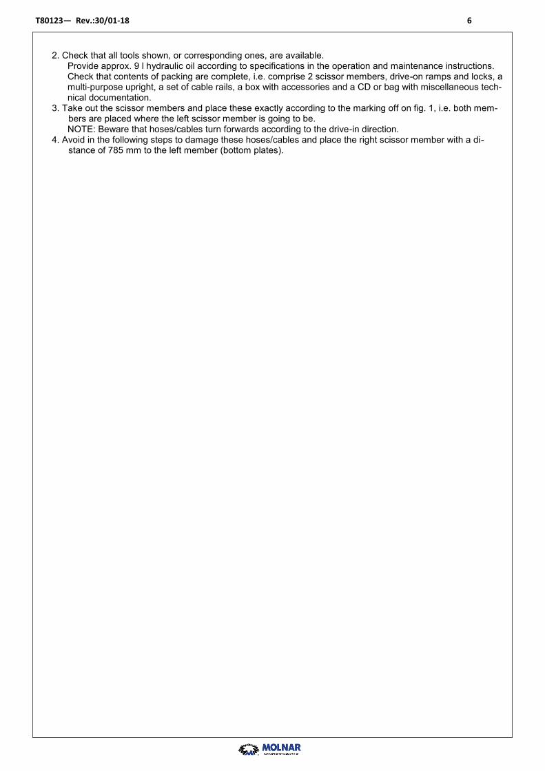
2. Check that all tools shown, or corresponding ones, are available. Provide approx. 9 l hydraulic oil according to specifications in the operation and maintenance instructions. Check that contents of packing are complete, i.e. comprise 2 scissor members, drive-on ramps and locks, a multi-purpose upright, a set of cable rails, a box with accessories and a CD or bag with miscellaneous tech-nical documentation.
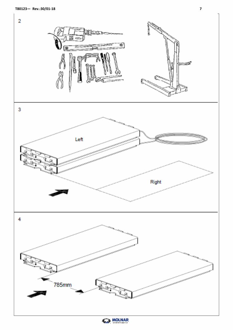
3. Take out the scissor members and place these exactly according to the marking off on fig. 1, i.e. both mem-bers are placed where the left scissor member is going to be. NOTE: Beware that hoses/cables turn forwards according to the drive-in direction.
4. Avoid in the following steps to damage these hoses/cables and place the right scissor member with a di-stance of 785 mm to the left member (bottom plates).
T80123— Rev.:30/01-18 7

T80123— Rev.:30/01-18 8
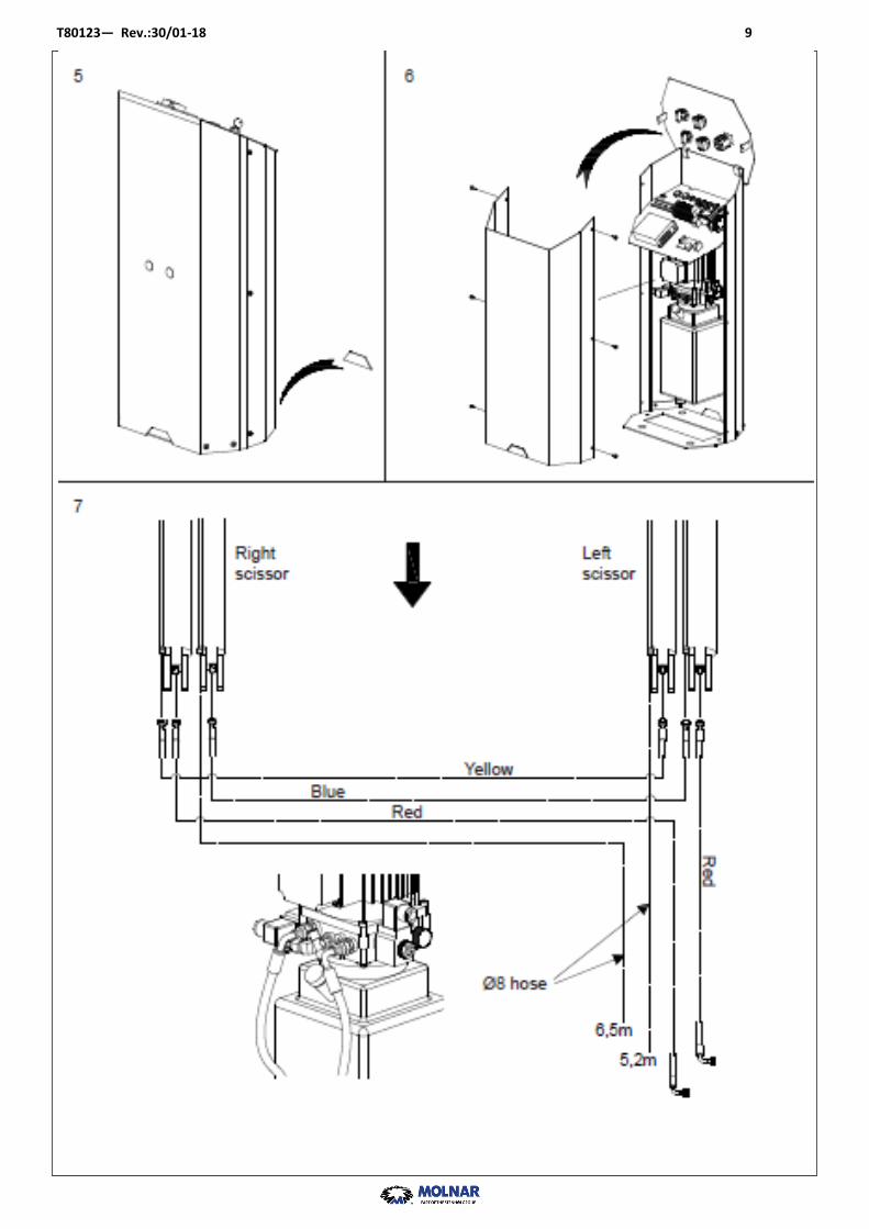
5. Place upright as required – NOTE: should the customer wish to place the upright towards the cable rails some material can be removed from the front cover of the upright.
6. Dismantle front cover and control panel for upright. 7. Fit hydraulic hoses marked with red in pump unit. Ø8 oil return hoses and the hydraulic hoses marked with yellow and blue are to be fitted later on (see fig. 10). Place loose ends of hoses in a bucket in order to avoid oil spillage.
T80123— Rev.:30/01-18 9

T80123— Rev.:30/01-18 10
8. Fill in approx. 9 l hydraulic oil. 9. Connection to mains (only to be carried out by authorized electrician) - Wiring diagram is included in control box. - Turn main switch on upright into 0-position before starting installation - Connect according to wiring diagram - IMPORTANT ! Connect to correct voltage – see fig. 9. 10. Push UP-button and by-passing button (see fig. 14). Turn main switch on upright into position ”1”. Check that power lamp on control panel is alight.
Check direction of rotation of pump motor by pushing UP-button shortly. If lift does not raise, disconnect power and interchange 2 phase cables. Try again. Rsise lift to reuired working height. Fit the hydraulic hoses marked with blue and yellow as shown (fig. 7.) Ar-range Ø8 oil return hoses together with cables for photocell and top and bottom limit switches forward to requi-red position of upright.
11. Fit oil return hoses in pump unit as shown.

T80123— Rev.:30/01-18 11

T80123— Rev.:30/01-18 12
12. Fit cables for photocells in control unit as shown. 13. Fit cables for top and bottom switches in control unit as shown. 14. Push UP-button and by-passing button (see fig. 14) to raise lift to max. height, hereby filling the cylinders with
oil and “driving” air out of the system. Lower lift again to bottom position by pushing the DOWN-button. Repeat this step as often as necessary to be sure that cylinders have been filled up and all air has been expel-led from the system. Check oil level and fill up if necessary.
Repeat this procedure once every 6 months. 15. Run the lift up and down a couple of times; note that buzzer is activated a little before the bottom position (see
fig. 15). Check that lifting height is max. 1950mm – if not: adjust top limit switch according to the operation and mainte-nance instructions.

T80123— Rev.:30/01-18 13

T80123— Rev.:30/01-18 14
16. Raise lift to required height. Check distance and perpendicularity between scissor members once again. Note: if floor is not 100% level lift must be shimmed up by means of metal shims, and the whole bottom frame must be supported. In case the lift has to be shimmed up more than 5mm, the bottom plates must be grouted.
17. Drill with ø16 holes through bed plates to a depth of 122 mm and clean hole. Insert expansion bolts supplied (4 off in each bed plate). Tighten expansion bolts with 80 N/m. Cut off exceeding thread.
18. Collect and assemble all hoses and cables with strips.

T80123— Rev.:30/01-18 15

T80123— Rev.:30/01-18 16
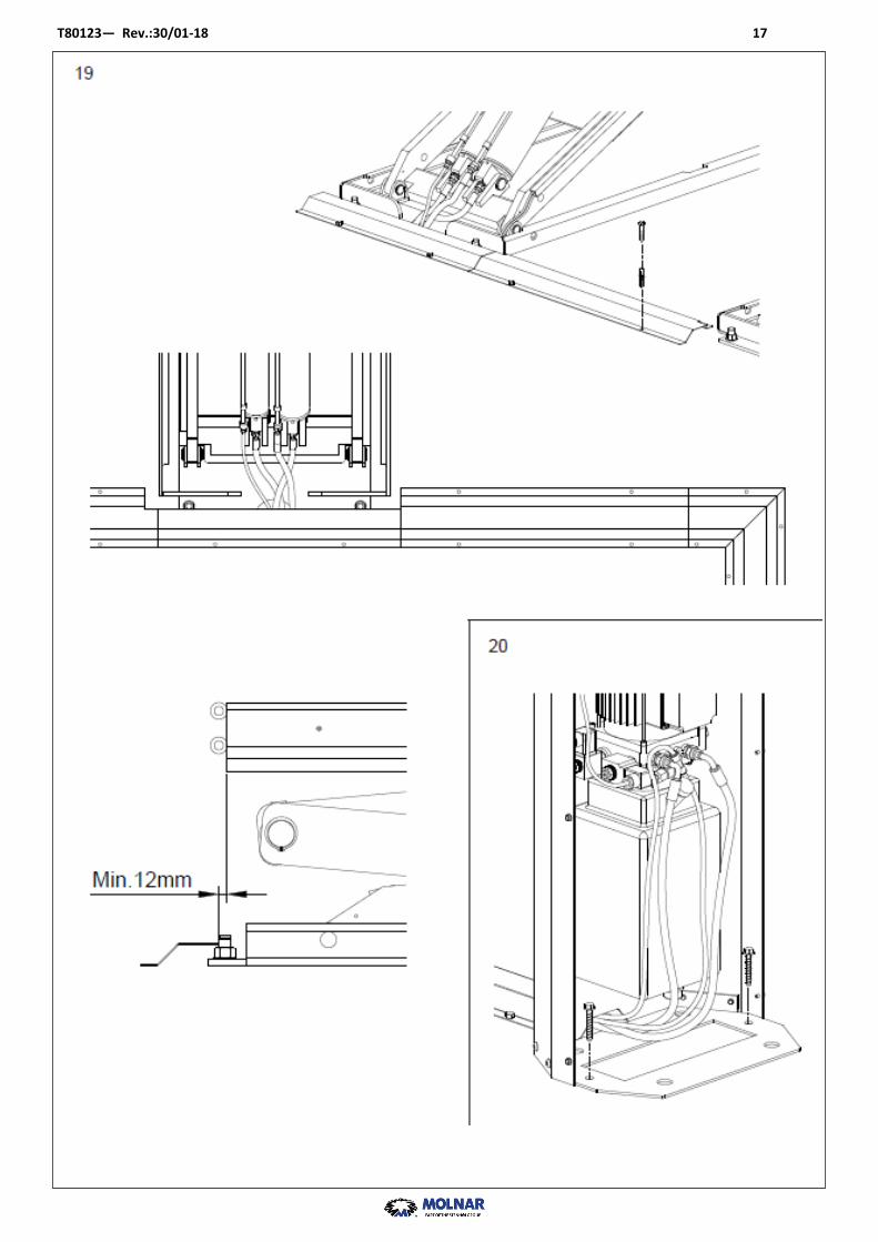
19. Place cable cover plates as required, mark up and drill with ø10x45. Fasten cover plates by means of fischer dowels and bolts supplied. Note ! The distance dimensions must be respected.
20. Check positioning of upright once again. Fasten it to floor by means of expansion bolts supplied.
T80123— Rev.:30/01-18 17

T80123— Rev.:30/01-18 18
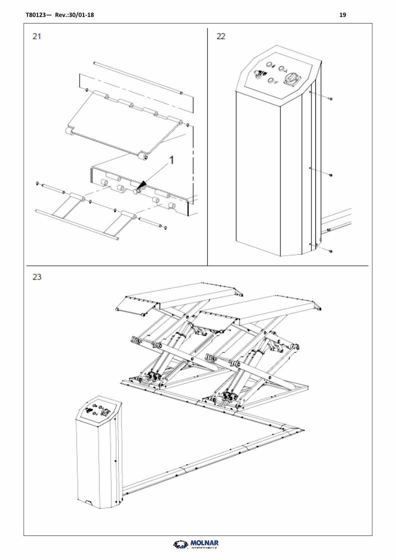
21. Raise lift to appropriate working height and fit drive-on ramps. Grease rollers and axles. Note ! Ramps and locks will be marked from factory to ensure correct fitting. Handle for locks has to be fitted at the
outer side of lift. Adjust the pre-fitted carriage bolts if needed.
22. Re-fit control panel and front cover for upright. 23. Clean lift, test with car and give user thorough instructions.
T80123— Rev.:30/01-18 19