3xlogic rtu guide - ossiossi-usa.com/public/manuals/3xlogic_vigil_rtu_guide.pdf_____ 3xlogic rtu...
TRANSCRIPT

3xLogic RTU Guide
Version 3.x
______________________________ 3xLogic RTU Guide Ver 3.x _____________________________
Copyright © 1999- 2014 OSSI LLC. 2
Intelli-Site Security Management Software
3xLogic Vigil RTU Guide
PC Software RTU Interface Guide
For Windows 7 SP1, 2008 R2 SP1, XP SP3 & 2003 SP2
Version 3.x Copyright © 1999 – 2014 OSSI LLC.

______________________________ 3xLogic RTU Guide Ver 3.x _____________________________
Copyright © 1999- 2014 OSSI LLC. 3
Copyright Copyright © 1999-2012 OSSI LLC. All rights
reserved.
Information in this document is subject to
change without notice. The software described in this document is furnished under a license
agreement or nondisclosure agreement. The software may be used or copied only in
accordance with the terms of those
agreements. No part of this publication may be reproduced, stored in a retrieval system, or
transmitted in any form or any means electronic or mechanical, including
photocopying and recording for any purpose other than the purchaser’s use without the
written permission of OSSI
OSSI W228 N727 Westmound Drive
Waukesha WI 53186 TEL: 262-522-1870
FAX: 262-522-1870
Trademarks Intelli-Site® is a registered trademark of OSSI
LLC. Intelli-Site® is registered in U.S. Patent
& Trademark Office.
All other registered and unregistered trademarks are the sole property of their
respective owners.

______________________________ 3xLogic RTU Guide Ver 3.x _____________________________
Copyright © 1999- 2014 OSSI LLC. 4
Table of Contents Copyright ................................................................................... 3
Trademarks .............................................................................. 3
Table of Contents ................................................................. 4
Section 1 – Introduction .................................................. 5
Overview ...................................................................................... 5
Technical Support Assistance .............................................. 6
OSSI Headquarters ............................................................ 6
Technical Support .............................................................. 6
Section 2 – Installation Note ........................................ 7
Section 3 - 3xLogic DVR Setup (Design Mode) .. 8
Adding DVR Nodes ................................................................... 8
Configuring the DVR Node .................................................... 8
Programming Examples for Run Mode ........................... 11
Section 4 – 3xLogic DVR Mode................................... 17
Using the DVR Mode ............................................................. 17
Using the Multi View Mode (Video Display Area) ....... 26
Main Video Controls......................................................... 26
______________________________ 3xLogic RTU Guide Ver 3.x _____________________________
Copyright © 1999- 2014 OSSI LLC. 5
Section 1 – Introduction
This section describes the following:
Overview
Technical Support Assistance
Overview
The RTU (Receiver/Transmitter Unit) is the Intelli-Site software representation of the Ionit
Digital Video Recorder (DVR). For purposes of this document, the term RTU is synonymous
with a 3xLogic DVR.
______________________________ 3xLogic RTU Guide Ver 3.x _____________________________
Copyright © 1999- 2014 OSSI LLC. 6
Technical Support Assistance
OSSI Headquarters W228 N727 Westmound Drive Waukesha WI 53186 USA
Tel: 262-522-1870 Fax: 262-522-1872
Technical Support
Technical support is available via Telephone,
Fax or Email. Contact OSSI Technical Support 8:00 AM to 5:00 PM Central Standard time. If
calling after hours, please leave a detailed voice mail message, and someone will return
your call as soon as possible.
E-Mail: [email protected] Fax: 262-522-1872 (Attention Technical Support)
Local: 262-522-1870
When calling, please be at the computer prepared to provide the following information:
Product version number, found by selecting
the About button from the Intelli-Site Menu Application Bar.
Product serial number used for registration.
The type of computer being used including, operating system, processor type, speed,
amount of memory, type of display, etc. Exact wording of any messages that appear
on the screen. What was occurring when the problem was
detected? What steps have been taken to reproduce
the problem?

______________________________ 3xLogic RTU Guide Ver 3.x _____________________________
Copyright © 1999- 2014 OSSI LLC. 7
Section 2 – Installation Note
When the ‘Vigil SDK’ installer appears, always select ‘Next’, ‘Continue’ and ‘Finish’. If prompted to restart the computer, select ‘Cancel’.

______________________________ 3xLogic RTU Guide Ver 3.x _____________________________
Copyright © 1999- 2014 OSSI LLC. 8
Section 3 - 3xLogic DVR Setup (Design Mode)
This section discusses the setup of 3xLogic DVRs in the project in Graphic Design mode.
Adding DVR Nodes
DVR nodes reside under an Area in the System Layout (see figures below):
As displayed, the first step is to add an ‘3xLogic Vigil’ node from the list in the ‘Add Node’ dialog.
Configuring the DVR Node
After a DVR node has been added, it needs to be
configured. This is accomplished by Rick-Clicking and editing the properties of the DVR node:
1. General Protocol Node Setting Tab allows you to adjust the following properties:
a. Change the name of the DVR.

______________________________ 3xLogic RTU Guide Ver 3.x _____________________________
Copyright © 1999- 2014 OSSI LLC. 9
b. Select the Access Level.
c. The Domain is system-selected.
d. The Node Type is General and fixed.
e. The Address field should not be changed here.
f. The driver field will default to Ionit – do not change.
g. The Protocol field should remain blank.
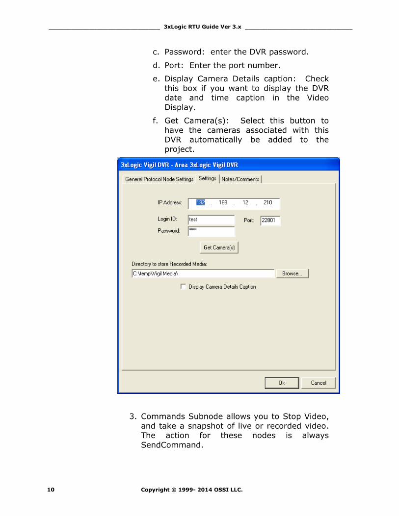
2. Settings Tab allows you to change the connection parameters:
a. IP Address: enter the IP address of the
DVR.
b. Login ID: enter the DVR user
identification.
______________________________ 3xLogic RTU Guide Ver 3.x _____________________________
Copyright © 1999- 2014 OSSI LLC. 10
c. Password: enter the DVR password.
d. Port: Enter the port number.
e. Display Camera Details caption: Check
this box if you want to display the DVR date and time caption in the Video
Display.
f. Get Camera(s): Select this button to
have the cameras associated with this DVR automatically be added to the
project.
3. Commands Subnode allows you to Stop Video,
and take a snapshot of live or recorded video. The action for these nodes is always
SendCommand.
______________________________ 3xLogic RTU Guide Ver 3.x _____________________________
Copyright © 1999- 2014 OSSI LLC. 11
4. Cameras Sub node allows you to connect to
the available camera channels. The action for these nodes is always SendCommand.
5. PTZ Control Subnode allows you to execute Pan, Tilt and Zoom commands against camera
channels that are appropriately equipped with PTZ controllers. The action for these nodes is
always SendCommand.
6. Presets Sub node allows you to set PTZ
cameras to various preset positions. The action for these nodes is always
SendCommand.
Programming Examples for Run Mode
After a DVR node has been configured in the design
tree you can use elements of the DVR node for a
variety of Run Mode applications. The following Section details some examples of DVR applications
that can be programmed for Run Mode:
1. Live Video Display and Control
Programming Example
The following programming example will detail
the steps necessary to create a video display object and various controls that will allow video
switching on a Run Mode Screen.
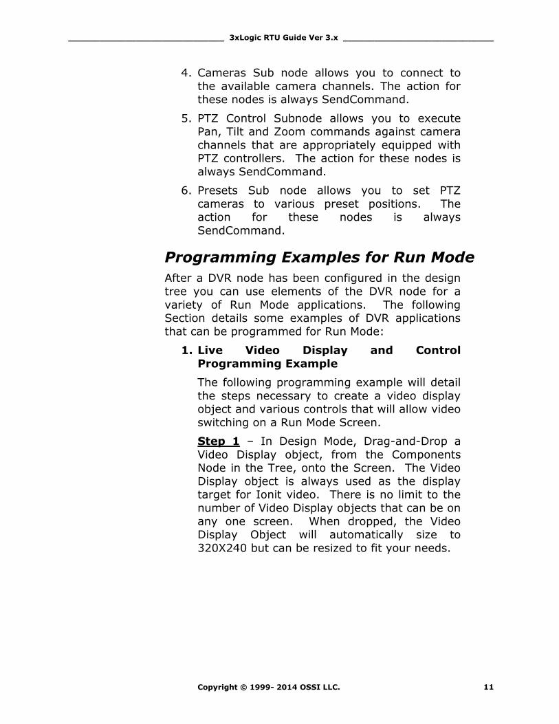
Step 1 – In Design Mode, Drag-and-Drop a
Video Display object, from the Components Node in the Tree, onto the Screen. The Video
Display object is always used as the display target for Ionit video. There is no limit to the
number of Video Display objects that can be on
any one screen. When dropped, the Video Display Object will automatically size to
320X240 but can be resized to fit your needs.
______________________________ 3xLogic RTU Guide Ver 3.x _____________________________
Copyright © 1999- 2014 OSSI LLC. 12
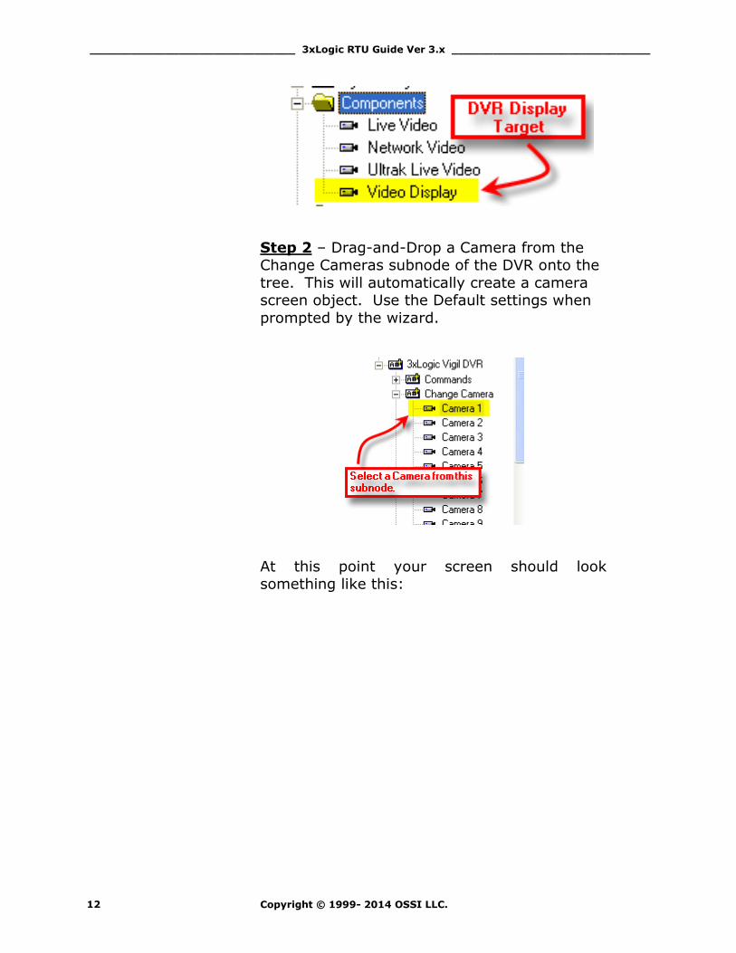
Step 2 – Drag-and-Drop a Camera from the Change Cameras subnode of the DVR onto the
tree. This will automatically create a camera screen object. Use the Default settings when
prompted by the wizard.
At this point your screen should look something like this:
______________________________ 3xLogic RTU Guide Ver 3.x _____________________________
Copyright © 1999- 2014 OSSI LLC. 13
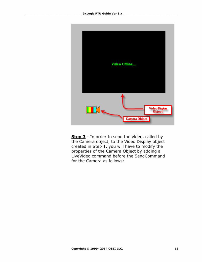
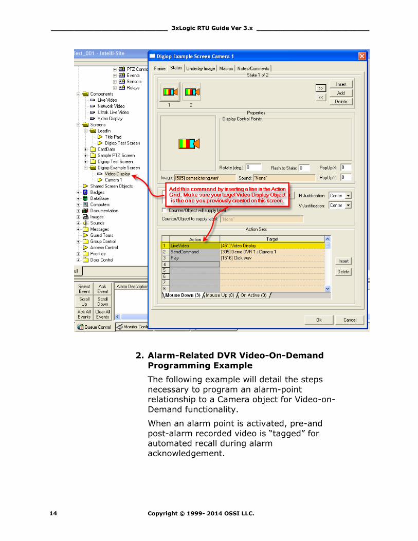
Step 3 - In order to send the video, called by the Camera object, to the Video Display object
created in Step 1, you will have to modify the properties of the Camera Object by adding a
LiveVideo command before the SendCommand for the Camera as follows:
______________________________ 3xLogic RTU Guide Ver 3.x _____________________________
Copyright © 1999- 2014 OSSI LLC. 14
2. Alarm-Related DVR Video-On-Demand
Programming Example
The following example will detail the steps
necessary to program an alarm-point relationship to a Camera object for Video-on-
Demand functionality.
When an alarm point is activated, pre-and
post-alarm recorded video is “tagged” for automated recall during alarm
acknowledgement.

______________________________ 3xLogic RTU Guide Ver 3.x _____________________________
Copyright © 1999- 2014 OSSI LLC. 15
Step 1 – Using any I/O point in the tree (in
this case we are using a Virtual Point) you can set the properties of the I/O point to enable
pre- or post-alarm recording (or both) as shown below:
Step 2 – Upon I/O point activation the alarm will appear in the Queue with a video-
associated icon as shown below:
______________________________ 3xLogic RTU Guide Ver 3.x _____________________________
Copyright © 1999- 2014 OSSI LLC. 16
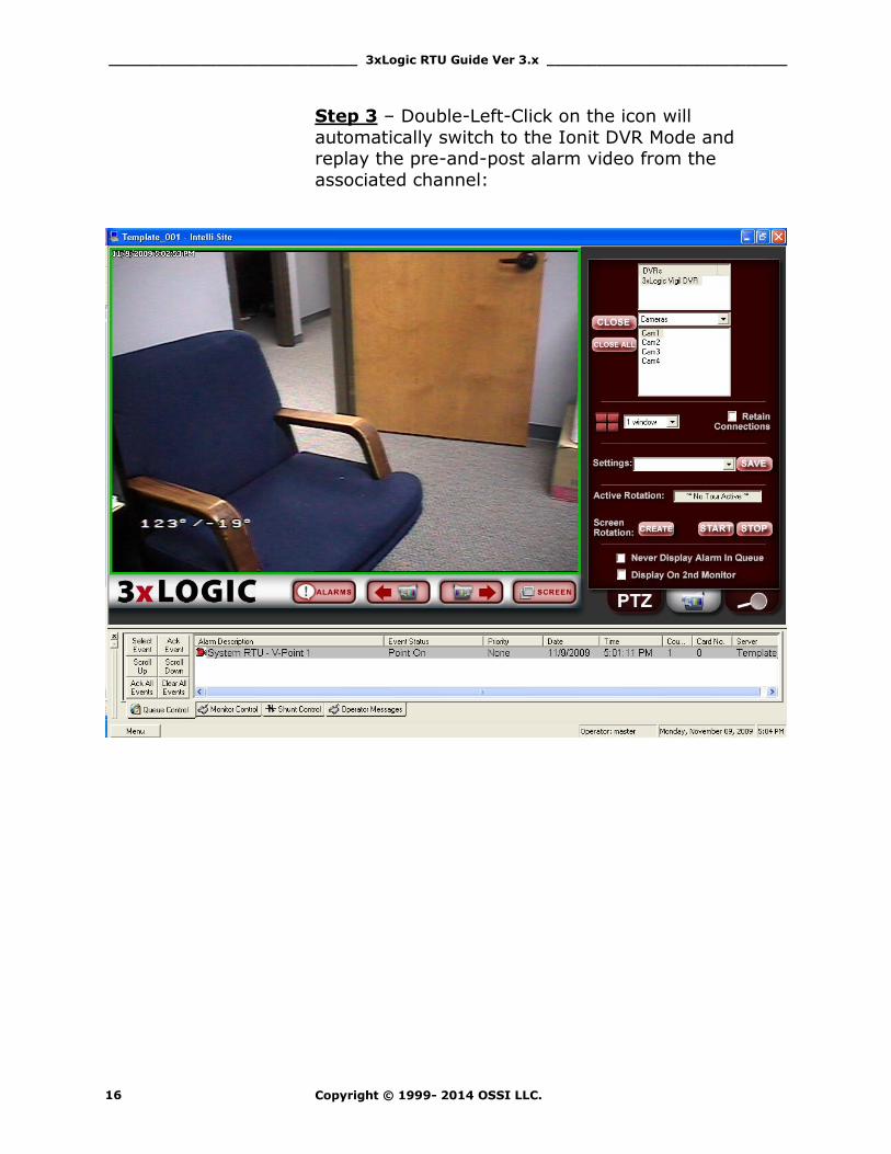
Step 3 – Double-Left-Click on the icon will
automatically switch to the Ionit DVR Mode and replay the pre-and-post alarm video from the
associated channel:

______________________________ 3xLogic RTU Guide Ver 3.x _____________________________
Copyright © 1999- 2014 OSSI LLC. 17
Section 4 – 3xLogic DVR Mode This section discusses the use of the 3xLogic DVR Multi
View Mode.
Using the DVR Mode
Click on the icon on the Application Menu bar
in order to switch to the DVR Mode.
1. General Settings Tab allows you to set
display, control, and camera tour parameters.
______________________________ 3xLogic RTU Guide Ver 3.x _____________________________
Copyright © 1999- 2014 OSSI LLC. 18
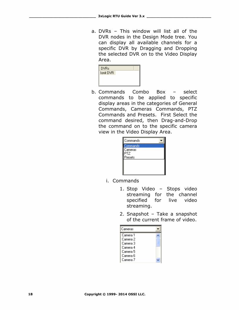
a. DVRs – This window will list all of the
DVR nodes in the Design Mode tree. You can display all available channels for a
specific DVR by Dragging and Dropping the selected DVR on to the Video Display
Area.
b. Commands Combo Box – select commands to be applied to specific
display areas in the categories of General Commands, Cameras Commands, PTZ
Commands and Presets. First Select the command desired, then Drag-and-Drop
the command on to the specific camera view in the Video Display Area.
i. Commands
1. Stop Video – Stops video
streaming for the channel specified for live video
streaming.
2. Snapshot – Take a snapshot
of the current frame of video.

______________________________ 3xLogic RTU Guide Ver 3.x _____________________________
Copyright © 1999- 2014 OSSI LLC. 19
ii. Camera Commands – Lists all of
the camera channels available for the selected DVR in the DVRs list.
Drag-and-Drop the desired Camera on to the specific view in the Video
Display Area.
iii. PTZ Control Commands – Drag-
and-Drop the desired PTZ control
command on to the specific view in the Video Display Area in order to
execute that command. This, of course, only works if the camera is
PTZ-capable.
c. Close button – stops a selected video channel.
d. Close ALL Button - stops all
video channels.
e. Screen Division – The Screen Division
window allows you to select the number, and layout, of video display windows in
the Video Display Area.
i. Screen Division Combo Box –
allows you to select from 1, 4, 8, 9, 10, 13, 16, 25 or 36 windows for
the Video Display Area.
ii. Retain Connections – checking this box will retain currently-connected
video channels when you switch from one division settings to
another.
______________________________ 3xLogic RTU Guide Ver 3.x _____________________________
Copyright © 1999- 2014 OSSI LLC. 20
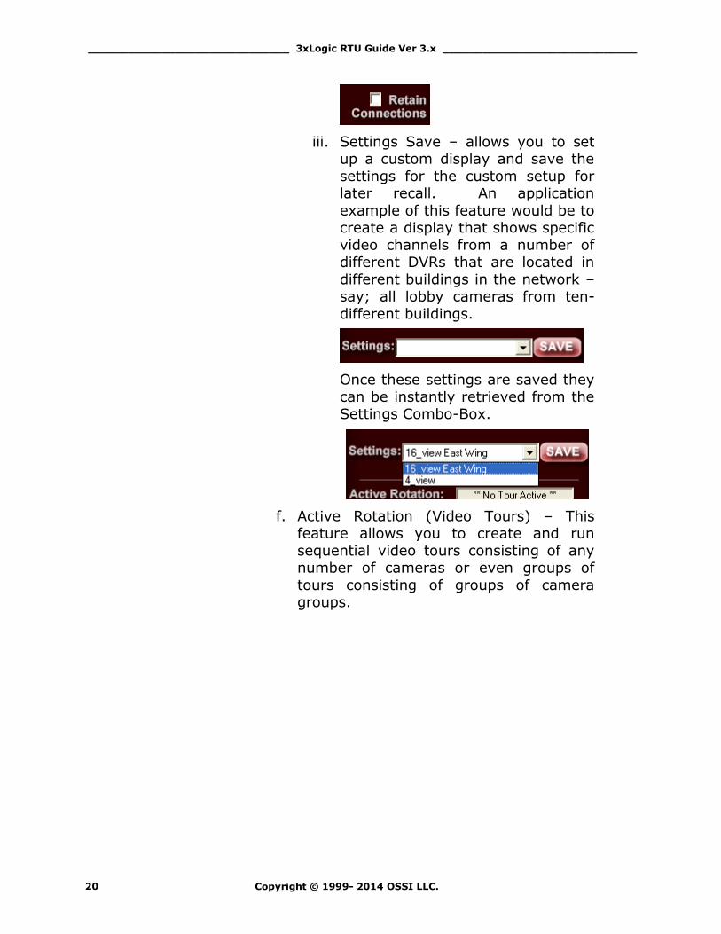
iii. Settings Save – allows you to set up a custom display and save the
settings for the custom setup for later recall. An application
example of this feature would be to create a display that shows specific
video channels from a number of different DVRs that are located in
different buildings in the network – say; all lobby cameras from ten-
different buildings.
Once these settings are saved they
can be instantly retrieved from the Settings Combo-Box.
f. Active Rotation (Video Tours) – This feature allows you to create and run
sequential video tours consisting of any number of cameras or even groups of
tours consisting of groups of camera groups.
______________________________ 3xLogic RTU Guide Ver 3.x _____________________________
Copyright © 1999- 2014 OSSI LLC. 21
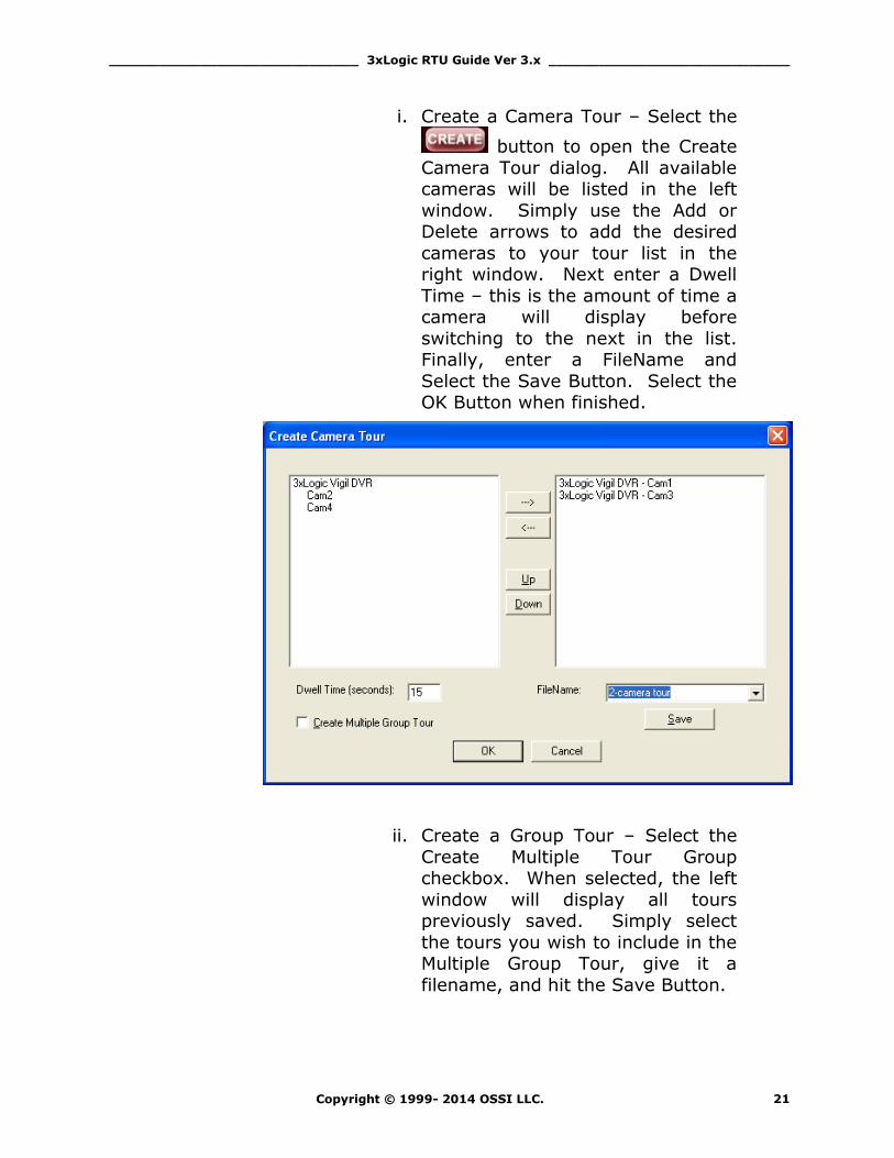
i. Create a Camera Tour – Select the
button to open the Create
Camera Tour dialog. All available cameras will be listed in the left
window. Simply use the Add or Delete arrows to add the desired
cameras to your tour list in the right window. Next enter a Dwell
Time – this is the amount of time a camera will display before
switching to the next in the list. Finally, enter a FileName and
Select the Save Button. Select the OK Button when finished.
ii. Create a Group Tour – Select the
Create Multiple Tour Group checkbox. When selected, the left
window will display all tours previously saved. Simply select
the tours you wish to include in the Multiple Group Tour, give it a
filename, and hit the Save Button.
______________________________ 3xLogic RTU Guide Ver 3.x _____________________________
Copyright © 1999- 2014 OSSI LLC. 22
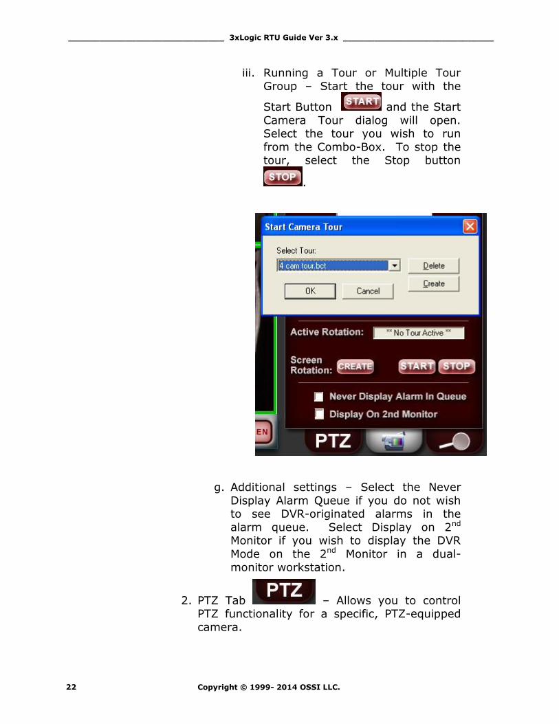
iii. Running a Tour or Multiple Tour
Group – Start the tour with the
Start Button and the Start
Camera Tour dialog will open. Select the tour you wish to run
from the Combo-Box. To stop the tour, select the Stop button
.
g. Additional settings – Select the Never
Display Alarm Queue if you do not wish to see DVR-originated alarms in the
alarm queue. Select Display on 2nd Monitor if you wish to display the DVR
Mode on the 2nd Monitor in a dual-
monitor workstation.
2. PTZ Tab – Allows you to control PTZ functionality for a specific, PTZ-equipped
camera.

______________________________ 3xLogic RTU Guide Ver 3.x _____________________________
Copyright © 1999- 2014 OSSI LLC. 23
3. Video Playback Tab - Allows you to accomplish Video File search, retrieval and
playback.
______________________________ 3xLogic RTU Guide Ver 3.x _____________________________
Copyright © 1999- 2014 OSSI LLC. 24
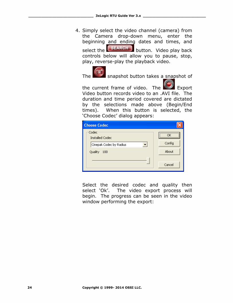
4. Simply select the video channel (camera) from
the Camera drop-down menu, enter the beginning and ending dates and times, and
select the button. Video play back controls below will allow you to pause, stop,
play, reverse-play the playback video.
The snapshot button takes a snapshot of
the current frame of video. The Export
Video button records video to an .AVI file. The duration and time period covered are dictated
by the selections made above (Begin/End times). When this button is selected, the
‘Choose Codec’ dialog appears:
Select the desired codec and quality then
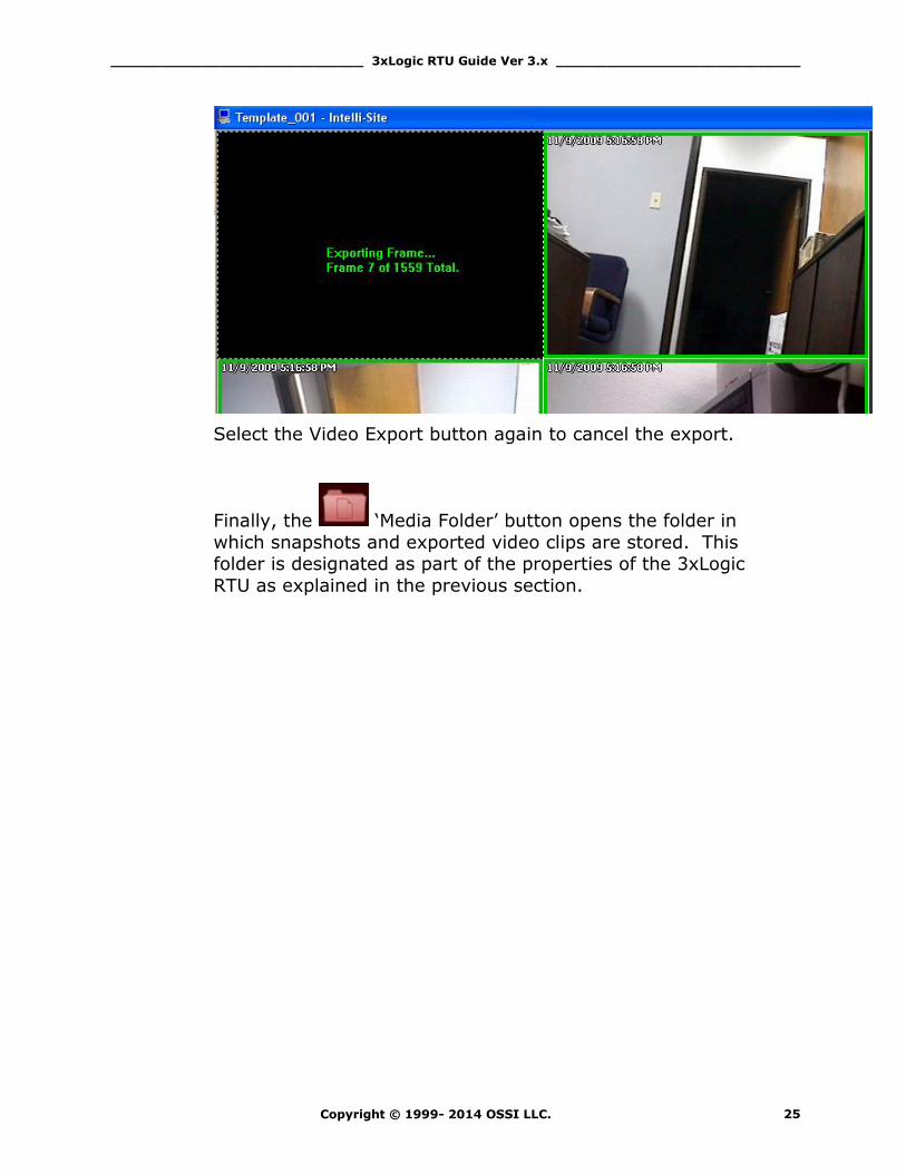
select ‘Ok’. The video export process will begin. The progress can be seen in the video
window performing the export:
______________________________ 3xLogic RTU Guide Ver 3.x _____________________________
Copyright © 1999- 2014 OSSI LLC. 25
Select the Video Export button again to cancel the export.
Finally, the ‘Media Folder’ button opens the folder in
which snapshots and exported video clips are stored. This folder is designated as part of the properties of the 3xLogic
RTU as explained in the previous section.
______________________________ 3xLogic RTU Guide Ver 3.x _____________________________
Copyright © 1999- 2014 OSSI LLC. 26
Using the Multi View Mode (Video
Display Area)
The main window (Video Display Area) of multi view consists of a viewing area and four control buttons.
If you double-click on any of the individual video display views, the view will expand to full size. To return, simply double-click on the full-size view.
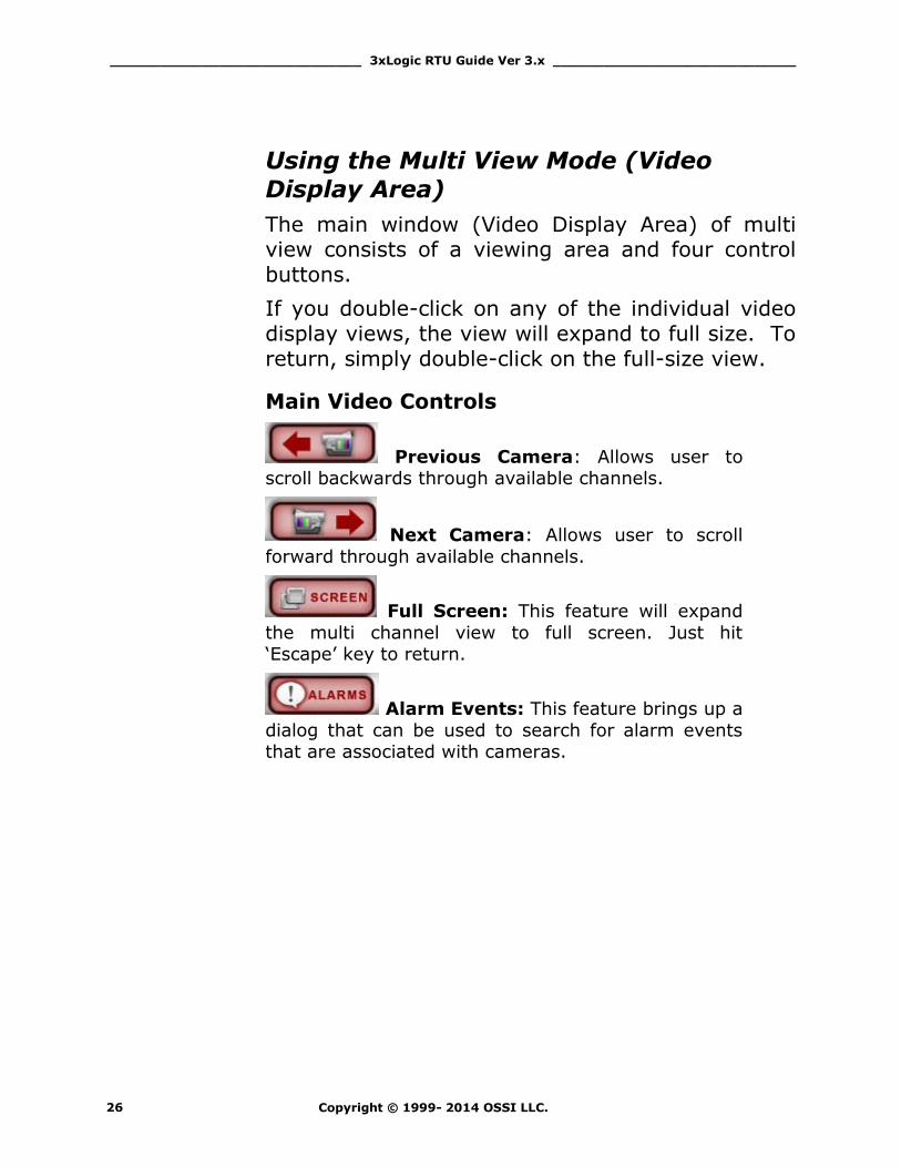
Main Video Controls
Previous Camera: Allows user to scroll backwards through available channels.
Next Camera: Allows user to scroll
forward through available channels.
Full Screen: This feature will expand
the multi channel view to full screen. Just hit ‘Escape’ key to return.
Alarm Events: This feature brings up a
dialog that can be used to search for alarm events that are associated with cameras.

______________________________ 3xLogic RTU Guide Ver 3.x _____________________________
Copyright © 1999- 2014 OSSI LLC. 27