4. at vertical openings in the performance area of...
TRANSCRIPT

IBC–E104 ICC PUBLIC HEARING ::: February 2008
4. At vertical openings in the performance area of stages and platforms. 5. At elevated walking surfaces appurtenant to stages and platforms for access to and utilization of special
lighting or equipment. 6. Along vehicle service pits not accessible to the public. 7. In assembly seating where guards in accordance with Section 1025.14 are permitted and provided.
2. Add new text as follows: 1013.1.1 (IFC [B] 1013.1.1) Glazing. Where glass is used to provide a guard or as a portion of the guard system, the guard shall also comply with Section 2407. Where the glazing provided does not meet the strength and attachment requirements in Section 1607.7, complying guards shall also be located along glazed sides of open-sided walking surfaces. 3. Revise as follows: 1013.2 (IFC [B] 1013.2) (Supp) Height. Required guards shall form a protective barrier be not less than 42 inches (1067 mm) high, measured vertically above the adjacent walking surfaces, adjacent fixed seating or the line connecting the leading edge edges of the tread treads , adjacent walking surface or adjacent seatboard.
Exceptions:
1. For occupancies in Group R-3, and within individual dwelling units in occupancies in Group R-2, guards whose top rail also serves as a handrail shall have a height not less than 34 inches (864 mm) and not more than 38 inches (965 mm) measured vertically from the leading edge of the stair tread nosing. guards on the open sides of stairs shall have a height not less than 34 inches (864 mm) measured vertically from a line connecting the leading edges of the treads.
2. For occupancies in Group R-3, and within individual dwelling units in occupancies in Group R-2, where the top of the guard also serves as a handrail on the open sides of stairs, the top of the guard shall not be less than 34 inches (864 mm) and not more than 38 inches (965 mm) measured vertically from a line connecting the leading edges of the treads.
2. 3. The height in assembly seating areas shall be in accordance with Section 1024.14. 3. 4. Along alternating tread device, guards whose top rail also serves as a handrail, shall have height not less
than 30 inches (762 mm) and not more than 34 inches (864 mm), measured vertically from the leading edge of the device tread nosing.
1013.3 (IFC [B] 1013.3) (Supp) Opening limitations. Open Required guards shall have balusters or ornamental patterns such that a not have openings which allow passage of a sphere 4-inch- inches (102 mm) diameter sphere in diameter from the walking surface to the required guard height cannot pass through any opening up to a height of 34 inches (864 mm). From a height of 34 inches (864 mm) to 42 inches (1067 mm) above the adjacent walking surfaces, a sphere 8 inches (203 mm) in diameter shall not pass.
Exceptions:
1. From a height of 36 inches (914 mm) to 42 inches (1067 mm), guards shall not have openings which allow passage of a sphere 4.375 inches (111 mm) in diameter.
1. 2. The triangular openings at the open sides of a stair, formed by the riser, tread and bottom rail, at the open side of a stairway shall be of a maximum size such that a sphere of 6 inches (152 mm) in diameter cannot pass through the opening. not allow passage of a sphere 6 inches (152 mm) in diameter.
2 3. At elevated walking surfaces for access to and use of electrical, mechanical or plumbing systems or equipment, guards shall have balusters or be of solid materials such that a sphere with a diameter of 21 inches (533 mm) cannot pass through any opening. not have openings which allow passage of a sphere 21 inches (533 mm) in diameter.
3. 4. In areas which are not open to the public within occupancies in Group I-3, F, H or S, and for alternating tread devices balusters, horizontal intermediate rails or other construction shall not permit a sphere with a diameter of 21 inches (533 mm) to pass through any opening. guards shall not have openings which allow passage of a sphere 21 inches (533 mm) in diameter.
4. 5. In assembly seating areas, guards at the end of aisles where they terminate at a fascia of boxes, balconies and galleries shall have balusters or ornamental patterns such that a not have openings which allow passage of a sphere 4 inch inches (102mm) in diameter sphere cannot pass through any opening up to a height of 26 inches (660 mm). From a height of 26 inches (660 mm) to 42 inches (1067 mm) above the adjacent walking surfaces, guards shall not have openings which allow passage of a sphere 8 inches (203 mm) in diameter shall not pass.

ICC PUBLIC HEARING ::: February 2008 IBC–E105
5. 6. Within individual dwelling units and sleeping units in Group R-2 and R-3 occupancies, openings for required guards on the sides of stair treads shall not allow a sphere of 4.375 inches (111 mm) to pass through. guards on the open sides of stairs shall not have openings which allow passage of a sphere 4.375 (111 mm) inches in diameter.
1013.4. (IFC [B] 1013.4) Screen porches. (No change to current text) 1013.5 (IFC [B] 1013.5) Mechanical equipment. Guards shall be provided where appliances, equipment, fans, roof hatch openings or other components that require service are located within 10 feet (3048 mm) of a roof edge or open side of a walking surface and such edge or open side is located more than 30 inches (762 mm) above the floor, roof or grade below. The guard shall be constructed so as to prevent the passage of a sphere 21 inch inches (533 mm) in diameter sphere. The guard shall extend not less than 30 inches (762 mm) beyond each end of such appliance, equipment, fan or component. 1013.6 (IFC [B] 1013.6) Roof access. Guards shall be provided where the roof hatch opening is located within 10 feet (3048 mm) of a roof edge or open side of a walking surface and such edge or open side is located more than 30 inches (762 mm) above the floor, roof or grade below. The guard shall be constructed so as to prevent the passage of a sphere 21 inch inches (533 mm) in diameter sphere. PART II – IRC BUILDING AND ENERGY 1. Revise as follows:
SECTION R312 GUARDS
R312.1 (Supp) Where Guards required. Guards shall be provided on all decks, landings, porches, balconies, ramps or raised floor surfaces located more than 30 inches (762 mm) above the floor or grade below.. Required guards shall not be less than 36 inches in height. Open sides of stairs with a total rise of more than 30 inches (762 mm) above the floor or grade below shall have guards not less than 34 inches (864 mm) in height measured vertically from the nosing of the treads. Guards shall be located along open-sided walking surfaces, including stairs, ramps and landings, that are located more than 30 inches measured vertically to the floor or grade below at any point within 36 inches ( 914 mm) horizontally to the edge of the open side Insect screening shall not be considered as a guard.
Porches and decks which are enclosed with insect screening shall be equipped with guards where the walking surface is located more than 30 inches (762 mm) above the floor or grade below. 2. Add new text as follows: R312.2 Height. Required guards at open-sided walking surfaces, including stairs, porches, balconies or landings, shall be not less than 36 inches (914 mm) high measured vertically above the adjacent walking surface, adjacent fixed seating or the line connecting the leading edges of the treads.
Exceptions:
1. Guards on the open sides of stairs shall have a height not less than 34 inches (864 mm) measured vertically
from a line connecting the leading edges of the treads. 2. Where the top of the guard also serves as a handrail on the open sides of stairs, the top of the guard shall
not be not less than 34 inches (864 mm) and not more than 38 inches (965 mm) measured vertically from a line connecting the leading edges of the treads.
3. Revise as follows: R312.2 R312.3 Guard Opening limitations. Required guards on open sides of stairways, raised floor areas, balconies and porches shall not have openings intermediate rails or ornamental closures which do not allow passage of a sphere 4 inches (102 mm) or more in diameter from the walking surface to the required guard height.
Exceptions:
1. The triangular openings at the open side of a stair, formed by the riser, tread and bottom rail of a guard, at the open side of a stairway shall are permitted to be of such a size that a sphere 6 inches cannot pass through. not allow passage of a sphere 6 inches (153 mm) in diameter.

IBC–E106 ICC PUBLIC HEARING ::: February 2008
2. Openings for required guards on the open sides of stair treads stairs shall not allow passage of a sphere 43/8 inches or more in diameter to pass through Guards on the open sides of stairs shall not have openings which allow passage of a sphere 4.375 inches (111 mm) in diameter
Reason: The ICC Board established the ICC Code Technology Committee (CTC) as the venue to discuss contemporary code issues in a committee setting which provides the necessary time and flexibility to allow for full participation and input by any interested party. The code issues are assigned to the CTC by the ICC Board as “areas of study”. Information on the CTC, including: meeting agendas; minutes; reports; resource documents; presentations; and all other materials developed in conjunction with the CTC effort can be downloaded from the following website: http://www.iccsafe.org/cs/cc/ctc/index.html. Since its inception in Aprril/2005, the CTC has held twelve meetings - all open to the public. This proposed change is a result of the CTC’s investigation of the area of study entitled “Climbable Guards”. The scope of the activity is noted as:
The study of climbable guards will focus on determining the need for appropriate measures to prevent or inhibit an individual from utilizing the elements of a guard system, including rails, balusters and ornamental patterns, to climb the guard, thereby subjecting that person to the falling hazard which the guard system is intended to prevent.
This proposal is a follow-up to E96 – 06/07.As of this writing this area of study has been completed by the CTC relative to these proposals. The general focus of these two proposals, one to the IBC and one to the IRC, is to create consistency in language regulating guards in the two codes. Part I – IBC IBC 1013.1. Laundry lists of items in the code are typically not all-inclusive. The word “including” provides this clarification in the following sections as well. This section is divided into two paragraphs with the second paragraph dealing with glass and glazing without a change in intent.
The key part of thjs change to IBC 1013.1 is submitted in order to clarify how the height measurement which triggers the guard requirement is made relative to proximity to the adjacent fall-off. This is illustrated in the following figure:
The view is taken from the landing of a 3 riser stair, looking towards the face of the risers.
IBC 1013.2: The technical portions of this change are the changes that stipulates that the provisions are applicable to only required guards and that a fixed seat becomes a potential walking surface to a child and thus warrants the guard height to be measured from that point. The remainder does not change the intent but rather provides standardized text dealing with stair treads and the determination of how to measure guard height. This public comment revises the term to “fixed seating” so as to clarify the measurement, using common terminology. Fixed seating represents a walking surface that is sure to be utilized by children. As such, the measurement of the guard must be taken from this location to address the hazard of a child falling over the guard. It is impossible for the code to regulate ornamentals such as planters, furniture and the like and this proposal does not intend to regulate them.

ICC PUBLIC HEARING ::: February 2008 IBC–E107
IBC 1013.3: This section is also clarified to apply to only required guards. In the disapproval of E96-06/07, committee notes that they feel that exceptions 1 and 2 are redundant. A careful reading of the text revisions reveals a subtle difference. Exception 1 is a general exception for guard height along stairs. Exception 2 addresses the guard height where the top of the guard serves as a handrail. This distinction is intended to provide clarification in the code for the two possible scenarios.
The majority of the revision in this section and exception involve editorial rewording of the sentences for clarity and consistency. The technical change is to exception 1 to reduce the maximum opening (8” to 4-3/8” inches) for this upper portion of the guard above 36 inches. The 8 inch limitation on openings at the upper section of the guard was based on the difference between the 34 inch height being the part of the guard that protects small children and the 42 inch height for the rest of the population. However this does not take into account that residential R-3 use groups require a minimum guard height of 36 inches. Proposed exception 1 raises the height for which the 4 inch opening requirement is applicable - to coincide with the minimum guard height of 36 inches in residential occupancies.
The change in maximum opening size at the upper portion of the guard, from the current 8 inch sphere criteria to a 4-3/8 inch sphere, is based on providing an equivalent level of protection as that provided by the current 4 inch opening on the lower portion of the guard. As a point of reference, the following measurements of head sizes of infants are excerpted from Drawing #2 Measurement of Infants from a book entitled “The Measure of Man and Woman: Human Factors” by Alvin R. Tilley, first published by Whitney Library of Design in 1993, republished and copyrighted by John Wiley & Sons, New York (ISBN 0-471-09955-4) in 2002. The publication states “We have chosen to accommodate 98% of the U.S. population, which lies between the 99 percentile and the 1 percentile, for product designs for civilians” page 10-11 headlined percentiles. Age Side-to-side measurement Back-to-front measurement 12-15 months: 5” 6.5” 16-19 months: 5” 6.5” 20-23 months: 5.1” 6.8”
Additional point of reference, from the same book entitled “The Measure of Man and Woman: Human Factors” by Alvin R. Tilley, figure number 8, page 14, showing child age 2.5 – 3 years. The chest dimension when scaled (1” = 12”) shows a 4-3/4” dimension from the back to the front. The following information from various resources has been compiled to illustrate how countries outside of the US are regulating the openings in guards:
Country of Origin Sphere Rule Metric Sphere Rule Inches Canada 100mm 3.94” United Kingdom 100mm 3.94” United States 102mm 4” Australia 125mm 4.92” Germany 120mm 4.72” France 110mm 4.33” Mexico (no code – standard followed) 102mm – 152mm 4” – 6” Russia 100mm 3.94” Romania 100mm 3.94” Trinidad & Tobago 102mm 4” Japan (Confirmation Pending) 125mm 4.92” Spain (Confirmation Pending) (120mm) (125mm) (4.72”) (4.92”) Switzerland 120mm 4.72” Sweden 100mm 3.94” Taiwan (Confirmation Pending) 125mm 4.92” Singapore (Confirmation Pending) 125mm 4.92” Poland ( Confirmation Pending) 100mm 3.94” Turkey 100 mm 3.94” Netherlands (Confirmation Pending) 100mm 3.94”
Part II – IRC IRC R312.1: This section is being divided into two sections, similar to the IBC. The first section includes the general guard requirement, and the new section (R312.2) includes the height requirements. See reason for IBC Section 1013.1. IRC R312.2: This new section includes the guard height requirements. It is reformatted to place emphasis on the 36” high guard required at level surfaces. There are not technical changes to the minimum height. As noted in the current text to IRC Section R312.2, the IRC applies to required guards. The term “required” is proposed here as well. This section uses the term “adjacent fixed seating” – intended to clarify that where there is built-in seating, the guard height is to be measured from the seat itself to provide for the minimum required height where it is assumed that children may be standing. See reason for IBC Section 1013.2.
IRC R312.3: The majority of the revision in this section and exception involve editorial rewording of the sentences for clarity and consistency. Bibliography: Interim Report No. 1 of the CTC, Area of Study – Climbable Guards, March 9, 2006. “The Measure of Man and Woman: Human Factors” by Alvin R. Tilley Cost Impact: The code change proposal will not increase the cost of construction. PART I – IBC MEANS OF EGRESS Public Hearing: Committee: AS AM D Assembly: ASF AMF DF PART II – IRC BUILDING AND ENERGY Public Hearing: Committee: AS AM D Assembly: ASF AMF DF

IBC–E108 ICC PUBLIC HEARING ::: February 2008
E86–07/08 1013.2 (IFC [B] 1013.2) Proponent: Thomas B. Zuzik Jr, Artistic Railings, Inc., representing himself Revise as follows: 1013.2 (IFC [B] 1013.2) (Supp) Height. Guards shall form a protective barrier not be less than 42 inches (1067 mm) high, measured vertically above the leading edge of the tread, adjacent walking surface or adjacent seatboard fixed seating. Exceptions:
1. For occupancies in Group R-3, and within individual dwelling units in occupancies in Group R-2, guards whose top rail also serves as a handrail shall have a height not less than 34 inches (864 mm) and not more than 38 inches (1067 mm) measured vertically from the leading edge of the stair tread nosing.
2. The height in assembly seating areas shall be in accordance with Section 1024.14. 3. Along alternating tread device, guards whose top rail also serves as a handrail, shall have height not less
than 30 inches (762 mm) and not more than 34 inches (864 mm), measured vertically from the leading edge of the device tread nosing.
Reason: .The wording to “form a protective barrier” describes a function and not the height and if used is more suited for section 1013.1 as 1013.2 is establishing the height of the guard only and were to measure it height from. The wording for 1013.2 should be limited to just the guard’s height as the sub-title states. 2. As noted in previous code cycles, proposals requesting the removal of the wording seatboard on the basis that a seatboard is not defined in the ICC family of codes and standards. With the constant debate over the wording a more appropriate term “fixed seating” is offered to clarify the intended location. Fixed meaning not movable and seating a product designed specifically for sitting on. This proposal is intended to simplify the wording published in 1013.2 height for the guard section of the building code. Cost Impact: The code change proposal will not increase the cost of construction. Public Hearing: Committee: AS AM D Assembly: ASF AMF DF E87–07/08 1013.2, (IFC [B] 1013.2) Proponent: Thomas Kinsman, T. A. Kinsman Consulting Company, representing himself Revise as follows: 1013.2 (IFC [B] 1013.2) (Supp) Height. Guards shall form a protective barrier not less than 42 inches (1067 mm) high, measured vertically above the leading edge of the tread, or adjacent walking surface or adjacent seatboard. Exceptions:
1. For occupancies in Group R-3, and within individual dwelling units in occupancies in Group R-2, guards whose top rail also serves as a handrail shall have a height not less than 34 inches (864 mm) and not more than 38 inches (1067 mm) measured vertically from the leading edge of the stair tread nosing.
2. The height in assembly seating areas shall be in accordance with Section 1024.14. 3. Along alternating tread device, guards whose top rail also serves as a handrail, shall have height not less
than 30 inches (762 mm) and not more than 34 inches (864 mm), measured vertically from the leading edge of the device tread nosing.
Reason: The proposal deletes the terms “adjacent seatboard” because it is an undefined term and therefore causes an unwarranted high liability exposure for design professionals and others in the construction industry. Is a seatboard always bench like? Can it be made out of materials other than wood? Is a wide parapet wall top a seat board if it is wide enough to sit on? If this proposal fails, there is a companion code change that proposes a definition for seatboard and include reference to it in the list of locations in 1013.1 of where guards are required Cost Impact: The code change will not increase the cost of construction. Public Hearing: Committee: AS AM D Assembly: ASF AMF DF

ICC PUBLIC HEARING ::: February 2008 IBC–E109
E88–07/08 1013.3, 1025.14.1 (IFC [B] 1013.3, 1025.14.1) Proponent: Christopher W. Bryant, spg3 Architects, representing himself Revise as follows: 1013.3 (IFC [B] 1013.3) (Supp) Opening limitations. Open guards shall have balusters or ornamental patterns such that a 4-inch-diameter (102 mm) sphere cannot pass through any opening up to a height of 34 inches (864 mm). From a height of 34 inches (864 mm) to 42 inches (1067 mm) above the adjacent walking surfaces, a sphere 8 inches (203 mm) in diameter shall not pass.
Exceptions:
1. The triangular openings formed by the riser, tread and bottom rail at the open side of a stairway shall be of a maximum size such that a sphere of 6 inches (152 mm) in diameter cannot pass through the opening.
2. At elevated walking surfaces for access to and use of electrical, mechanical or plumbing systems or equipment, guards shall have balusters or be of solid materials such that a sphere with a diameter of 21 inches (533 mm) cannot pass through any opening.
3. In areas that are not open to the public within occupancies in Group I-3, F, H or S, and for alternating tread devices, balusters, horizontal intermediate rails or other construction shall not permit a sphere with a diameter of 21 inches (533 mm) to pass through any opening.
4. In assembly seating areas where an elevation change of less than 30 inches occurs between a cross aisle and the adjacent floor or grade below, or between successive tiers of seating, guards complying with Section 1025.14 shall have balusters or ornamental patterns such that a sphere with a diameter of 21 inches (533 mm) can not pass through any opening.
4. 5. In assembly seating areas, guards at the end of aisles where they terminate at a fascia of boxes, balconies and galleries shall have balusters or ornamental patterns such that a 4-inch-diameter (102 mm) sphere cannot pass through any opening up to a height of 26 inches (660 mm). From a height of 26 inches (660mm) to 42 inches (1067 mm) above the adjacent walking surfaces, a sphere 8 inches (203 mm) in diameter shall not pass.
5. 6. Within individual dwelling units and sleeping units in Group R-2 and R-3 occupancies, openings for required guards on the sides of stair treads shall not allow a sphere of 4.375 inches (111 mm) to pass through.
1025.14 (IFC [B] 1025.14) Assembly guards. Assembly guards shall comply with Sections 1025.14.1 through 1025.14.3. 1025.14.1 (IFC [B] 1025.14.1) Cross aisles. Cross aisles located more than 30 inches (762 mm) above the floor or grade below shall have guards in accordance with Section 1013.
Where an elevation change of 30 inches (762 mm) or less occurs between a cross aisle and the adjacent floor or grade below, or between successive tiers of seating, guards not less than 26 inches (660 mm) above the aisle floor shall be provided.
Exception: Where the backs of seats on the front of the cross aisle project 24 inches (610 mm) or more above the adjacent floor of the aisle, a guard need not be provided.
Reason: The purpose of this change is to clarify the type of protection required in assembly spaces where there is a an elevation change of less than 30 inches. Section 1013.1 of the IBC only requires guards to be located along open sided walking surfaces that are located more than 30 inches above the floor or grade below. In assembly seating areas where there are open sided cross aisles or level changes between tiered seating sections and where the elevation change is less than 30 inches, a barrier is needed only to prevent occupants from stepping off the edge (especially in what might be a dimly lit environment). This protection can be provided in numerous ways including a simple railing. It should not be necessary to limit the size of openings between guard members to 4 inches because the IBC does not require such limitations for similar conditions elsewhere in a building. Requiring a 4 inch opening limitation for these types of edge protection would be overly restrictive and inconsistent with the general scoping paragraph in Section 1013.1. Limiting the openings to those that prevent the passage of a 21 inch sphere is consistent with the limitations in exceptions 2 and 3 and is more than adequate to provide the edge protection needed. It should also be noted that the exception in Section 1025.14.1 allows the edge protection to be provided by the backs of the seats in front as long as they extend a minimum of 24 inches above the level behind. Depending on the individual seat design there often may be more than 4 inches between individual seat backs within a row and there often may be more than 4 inches between the seat back and the leading edge of the upper tier or walking surface. Cost Impact: This code change will not increase the cost of construction. Public Hearing: Committee: AS AM D Assembly: ASF AMF DF

IBC–E110 ICC PUBLIC HEARING ::: February 2008
E89–07/08 1013.3 (IFC [B] 1013.3) Proponent: Lon McSwain, Mecklenburg County, NC, representing North Carolina Inspectors Association/Jim Bartl, Mecklenburg County, NC, representing AIA NC Code Committee Revise as follows: 1013.3 (IFC [B] 1013.3) (Supp) Opening limitations. Open guards shall have balusters or ornamental patterns such that a 4-inch-diameter (102 mm) sphere cannot pass through any opening up to a height of 34 inches (864 mm). From a height of 34 inches (864 mm) to 42 inches (1067 mm) above the adjacent walking surfaces, a sphere 8 inches (203 mm) in diameter shall not pass. A bottom rail or curb shall be provided such that a 2-inch-diameter (51mm) sphere cannot pass.
Exceptions:
1. The triangular openings formed by the riser, tread and bottom rail at the open side of a stairway shall be of a maximum size such that a sphere of 6 inches (152 mm) in diameter cannot pass through the opening.
2. At elevated walking surfaces for access to and use of electrical, mechanical or plumbing systems or equipment, guards shall have balusters or be of solid materials such that a sphere with a diameter of 21 inches (533 mm) cannot pass through any opening.
3. In areas that are not open to the public within occupancies in Group I-3, F, H or S, and for alternating tread devices, balusters, horizontal intermediate rails or other construction shall not permit a sphere with a diameter of 21 inches (533 mm) to pass through any opening.
4. In assembly seating areas, guards at the end of aisles where they terminate at a fascia of boxes, balconies and galleries shall have balusters or ornamental patterns such that a 4-inch-diameter (102 mm) sphere cannot pass through any opening up to a height of 26 inches (660 mm). From a height of 26 inches (660 mm) to 42 inches (1067 mm) above the adjacent walking surfaces, a sphere 8 inches (203 mm) in diameter shall not pass.
5. Within individual dwelling units and sleeping units in Group R-2 and R-3 occupancies, openings for required guards on the sides of stair treads shall not allow a sphere of 4.375 inches (111 mm) to pass through.
Reason: This requirement was in the Standard Building Code. More high rise residential buildings are being constructed and with them more occupied balconies. The danger of objects being pushed or rolling off and onto the public way is increasing. Reducing the gap at the bottom of the guard rail would reduce the size of objects that could be pushed or rolled of the balcony. Cost Impact: This code change will not increase the cost of construction. Public Hearing: Committee: AS AM D Assembly: ASF AMF DF
E90–07/08 421 (New), 1009.11.2, 1013.6, (IFC [B] 1009.11.2, [B] 1013.6), Chapter 35 (New) [IFC Chapter 45 (New)], IMC 304.10 Proponent: Basil Y. Tominna, PE, representing himself 1. Add new text as follows:
SECTION 421 ELIMINATION, PREVENTION OR CONTROL OF FALL HAZARDS
421.1 General. Where any part or component of the building, facility, structure or equipment requiring future maintenance work at high locations, the design shall incorporate fall prevention methods or techniques to eliminate fall hazards during occupancy and when performing maintenance work. The preferred order of control measures or the hierarchy of controls is to eliminate the need to work at heights such as designing out fall hazards, followed by prevention including installation guards as specified in Section 1013, and protection and control of fall hazards by identifying, designing and installing anchorages for safe use of fall arrest equipment and systems.

ICC PUBLIC HEARING ::: February 2008 IBC–E111
422.2 Compliance with other codes and standards. Elimination, prevention or control of fall hazards shall comply with the provisions and requirements of American National Standards Institute, ANSI Z359-Fall Protection Code, ANSI A1264.1 and DOL-29 CFR Part 1910, Subpart D. 2. Revise as follows: 1009.11.2 (IFC [B] 1009.11.2) Protection at roof hatch openings. Where the roof hatch opening providing the required access is located within 10 feet (3049 mm) of the roof edge to the roof, such roof access or roof edge shall be protected by guards installed in accordance with the provisions of Section 1013. 1013.6 (IFC [B] 1013.6) Roof access. Guards shall be provided where the roof hatch opening is located within 10 feet (3048 mm) of a roof edge or open side of a walking or working surface and such edge or open side is located more than 30 inches (762 mm) above the floor, roof or grade below. The guard shall be constructed so as to prevent the passage of a 21-inch-diameter (533 mm) sphere. Additional guards shall also be provided around the roof hatch opening with a gate on the roof access side. 3. Add standard to Chapter 35 (IFC Chapter 45) as follows: American National Standards Institute ANSI/ASSE Z359.0, 1, 2, 3 and 4 (2007) Fall Protection Code
Z359.0 Definitions and Nomenclature Used for Fall Protection and Fall Arrest Z359.1 Safety Requirements for Personal Fall Arrest Systems, Subsystems and Components Z359.2 Minimum Requirements for a Comprehensive Managed Fall Protection Program Z359.3 Safety Requirements for Positioning and Travel Restraint Systems Z359.4 Safety Requirements for Assisted-Rescue and Self-Rescue Systems, Subsystems and Components
ANSI/ASSE A1264.1-2007 Safety Requirements for Workplace Walking/Working Surfaces and Their Access; Workplace Floor and Wall Openings; Stairs and Guardrails Systems
US Department of Labor
29 CFR Part 1910, Subpart D (1970) Walking Working Surfaces
4. Revise IMC as follows: [B] 304.10 Guards. Guards shall be provided where appliances, equipment, fans or other components that require service and roof hatch openings are located within 10 feet (3048 mm) of a roof edge or open side of a walking surface and such edge or open side is located more than 30 inches (762 mm) above the floor, roof or grade below. The guard shall extend not less than 30 inches (762 mm) beyond each end of such appliances, equipment, fans, components and roof hatch openings and the top of the guard shall be located not less than 42 inches (1067 mm) above the elevated surface adjacent to the guard. The guard shall be constructed so as to prevent the passage of a 21-inch-diameter (533 mm) sphere and shall comply with the loading requirements for guards specified in the International Building Code. Additional guards shall also be provided around the roof hatch opening with a gate on the roof access side. Reason: International Building Code is based primarily on protecting occupants from failures of life safety provisions, structural collapse and property protection. However, it contains minimum requirement for health and safety. Although there are OSHA standards and requirements to address various safety hazards at work places, new design of buildings, facilities, structures and equipment are constructed or installed without taking into consideration the safety of personnel conducting maintenance work, after construction or installation is complete. The American National Standards Institute recently approved a new Fall Protection Code which includes series of standards developed by the ANSI/ASSE Z359 Committee addressing fall protection program requirements, systems and equipment. Effective date for the new code is 15 October 2007. The new fall protection code also addresses design requirements for fall protection systems in new buildings and facilities. Cost Impact: The code change to include fall protection in the design phase will slightly increase the cost during construction but will be more economical on the long run (during maintenance phase). Analysis: A review of the standard proposed for the inclusion in the code, ANSI/ASSE Z359.0, Z359.1, Z359.2, Z359.3 and Z359.4, A126.41 and US Dept. of Labor 29 CFR Part 1910 Subpart D, for compliance with the ICC criteria for referenced standards given in Section 3.6 of Council Policy #CP 28 will be posted on the ICC website on or before January 15, 2008. Public Hearing: Committee: AS AM D Assembly: ASF AMF DF

IBC–E112 ICC PUBLIC HEARING ::: February 2008
E91–07/08 1014.1 (IFC [B] 1014.1) Proponent: Anne R. vonWeller, Murray City, UT, representing Utah Chapter of ICC Revise as follows: 1014.1 (IFC [B] 1014.1) General. The exit access arrangement shall comply with Sections 1014 through 1017 and the applicable provisions of Sections 1003 through 1013. Exit access arrangement shall comply with Sections 1014 through 1017. Reason: The change is editorial and made to clarify all of the applicable requirements of 1003 through 1013 apply to the exit access, not just the provisions related to exit access arrangement. Cost Impact: The code change proposal will not increase the cost of construction. Public Hearing: Committee: AS AM D Assembly: ASF AMF DF
E92–07/08 1014.2 (IFC [B] 1014.2) Proponent: Gary Lampella, City of Redmond, OR, representing Oregon Officials Association Revise as follows: 1014.2 (IFC [B] 1014.2) (Supp) Egress through intervening spaces. Egress through intervening spaces shall comply with this section.
1. Egress from a room or space shall not pass through adjoining or intervening rooms or areas, except where such adjoining rooms or areas and the area served are accessory to the area served one or the other, are not a Group H occupancy and provide a discernible path of egress travel to an exit.
Exception: Means of egress are not prohibited through adjoining or intervening rooms or spaces in a Group H, S or F occupancy when the adjoining or intervening rooms or spaces are the same or a lesser hazard occupancy group.
2. Egress shall not pass through kitchens, storage rooms, closets or spaces used for similar purposes.
Exceptions:
1. Means of egress are not prohibited through a kitchen area serving adjoining rooms constituting
part of the same dwelling unit or sleeping unit. 2. Means of egress are not prohibited through stockrooms in Group M occupancies when all of the
following are met: 2.1. The stock is of the same hazard classification as that found in the main retail area; 2.2. Not more than 50 percent of the exit access is through the stockroom; 2.3. The stockroom is not subject to locking from the egress side; and 2.4. There is a demarcated, minimum 44-inch-wide (1118 mm) aisle defined by full or partial
height fixed walls or similar construction that will maintain the required width and lead directly from the retail area to the exit without obstructions.
3. An exit access shall not pass through a room that can be locked to prevent egress. 4. Means of egress from dwelling units or sleeping areas shall not lead through other sleeping areas,
toilet rooms or bathrooms. Reason: The code as currently written does not allow a small accessory use to egress through a larger space. Since the term “except where such adjoining rooms or areas are accessory to the area served” indicates that a larger space exiting though a smaller space is the only egress configuration that is allowed. An example would be a large retail store where there was a manager’s office that was accessory to the M occupancy. The office being an accessory use could have the occupants from the M egress through it, but you would not be permitted to egress from the office into the M occupancy because the M is not accessory to the office.

ICC PUBLIC HEARING ::: February 2008 IBC–E113
The definition for “accessory” can be found in Section 508.3.1 which limits them to being subsidiary to the main occupancy of the building, and not occupying more than 10 percent of area of the story in which they are located. . In essence the code prohibits an accessory use, such as described above, from exiting into the main occupancy of the building but allows the main occupancy, which could be considerably larger, to exit through the accessory use. Section 1014.2.1 was revised in Detroit via a public comment to recognize that some smaller separate tenants could have a means of egress through a larger separate tenant. This code change would simply allow one tenant space to have a means of egress that separate tenants are currently permitted to have. Cost Impact: The code change proposal will not increase the cost of construction. Public Hearing: Committee: AS AM D Assembly: ASF AMF DF
E93–07/08 1014.2.1 (IFC [B] 1014.2.1) Proponent: John Berry, Cole + Russell Architects, Inc Revise as follows: 1014.2.1 (IFC [B] 1014.2.1) Multiple tenants. Where more than one tenant occupies any one floor of a building or structure, each tenant space, dwelling unit and sleeping unit shall be provided with access to the required exits without passing through adjacent tenant spaces, dwelling units and sleeping units. Exception: The Means means of egress from a smaller tenant space shall not be prohibited from passing through
a larger adjoining tenant space where such rooms or spaces of the smaller tenant occupy less than 10 percent of the area of the larger tenant space through which they pass; are the same or similar occupancy group; a discernable path of egress travel to an exit is provided; and the means of egress into the adjoining space is not subject to locking from the egress side. A required means of egress serving the larger tenant space shall not pass through the smaller tenant space or spaces.
Reason: The intent of this code change is simply to add clarifying language as to which tenant space is egressing through the other. I have had several people ask for clarification on how this section was to be applied. I believe the original change was needed and appropriate, but it just needs a little more clarification. Cost Impact: The code change proposal will not increase the cost of construction. Public Hearing: Committee: AS AM D Assembly: ASF AMF DF
E94–07/08 1002.1 (New) (IFC [B] 1002.1 (New)) Proponent: Masoud Sabounchi, PE, CBO, Advanced Consulting Engineers, Inc., representing Colorado Chapter of ICC Add new definitions as follows: 1002.1 (IFC [B] 1002.1) Definitions. The following words and terms shall, for the purposes of this chapter and as used elsewhere in this code, have the meanings shown herein. SUITE. In a Group I-2 occupancy, a series of rooms or spaces or subdivided rooms separated from the remainder of the building by walls and doors. SUITES OF SLEEPING ROOMS. In a Group I-2 occupancy, a suite that contains one or more patient beds intended for overnight sleeping. SUITES OF NON-PATIENT SLEEPING ROOMS. In a Group I-2 occupancy, a suite that does not contain patient beds intended for overnight sleeping.
IBC–E114 ICC PUBLIC HEARING ::: February 2008
Reason: The above terminologies are used in Section 1014.2.2. However, these terminologies are not defined. Addition of the proposed definitions will provide a distinction between the suites of non-patient sleeping rooms and suites of sleeping rooms and help end use better implement provisions of Section 1014.2.2 through 1014.2.6. Cost Impact: The code change proposal will not increase the cost of construction. Public Hearing: Committee: AS AM D Assembly: ASF AMF DF
E95–07/08 1002.1, 1014.2.3 (IFC [B] 1002.1, [B] 1014.2.3) Proponent: Roger Severson, RSA Consulting, representing Oregon Department of Health Services 1. Add new definition as follows: 1002.1 (IFC [B] 1002.1) Definitions. The following words and terms shall, for the purposes of this chapter and as used elsewhere in this code, have the meanings shown herein. SUITE. A group of patient treatment rooms or patient sleeping rooms within Group I-2 occupancies where there is direct and constant visual supervision of all patients within the suite, and the suite is in conformance with the requirements of Section 1014.2.2 through 1014.2.6. 2. Revise as follows: 1014.2.3 (IFC [B] 1014.2.3) (Supp) Suites in patient sleeping areas. Patient sleeping areas in Group I-2 Occupancies shall be permitted to be divided into suites with one intervening room where if one of the following conditions is are met:
1. The intervening room within the suite is not used as an exit access for more than eight patient beds. 2. The arrangement of the suite allows for direct and constant visual supervision by nursing personnel.
Reason: Suite definition - The IBC currently contains some requirements for suites but there is not an explanation or definition to inform the reader as to the intent of the suite. The concept for suites to function within the code without corridor width or rating requirements were accepted to allow staff to have clear and unobstructed supervision of patients in specific treatment and sleeping rooms. It was not, and is not intended for day rooms or business sections of the hospital. Without a definition this concept is vague, leaving doubt and confusion for all who are responsible for the construction of suites within Health Care Facilities. Section 1014.2.3 - In order to avoid a conflict, a revision to Section 1014.2.3 of the 2007 supplement is needed that would require both items, rather than having a choice as proposed. Regardless of the concern for conflict, the existing code does not state that only one of the exceptions is permitted. The Oregon Health Care Facilities Committee is not sure why the original proposal allowed the choice? With this revision, Oregon is in support of the supplemental language and the proposals by Washington submitted for this cycle. The original proponent of this section, John Williams of the Construction Review Section of Washington’s DOH is in support of this revision. Cost Impact: Depending on previous codes used and/or other applicable codes today, this code change proposal will not increase the cost of construction. Public Hearing: Committee: AS AM D Assembly: ASF AMF DF
E96–07/08 1014.2.2.5 (New) [IFC [B] 1014.2.2.5 (New)] Proponent: Roger Severson, RSA Consulting, representing Oregon Department of Health Services Add new text as follows: 1014.2.2.5 (IFC [B] 1014.2.2.5) Exit access through suites. Exit access from all other portions of a building in a Group I-2 occupancy, including exit access from other suites, shall not pass through a suite.

ICC PUBLIC HEARING ::: February 2008 IBC–E115
Reason: Exit access not to pass through suites- This new section is an important concept which is implied but silent regarding the use of suites. Unlike the use of room to room, or intervening room exit access, suites have a very specific function for medical and health practices and should not be used as an exit access from other portions of the facility. Also, because suites are not required to have minimum access width or ratings within the suite for the benefit of operations and supervision, exit access from other portions of a facility should not be designed through this space. Cost Impact: Where there are areas that never had requirements in a previous code prior to the IBC, the code change proposal could cause an increase to the cost of construction. Public Hearing: Committee: AS AM D Assembly: ASF AMF DF
E97–07/08 1015.2, 1018.1, 1024.1, (IFC [B] 1015.2, [B] 1018.1, [B] 1024.1) Proponent: Gregory R. Keith, Professional heuristic Development, representing The Boeing Company Revise as follows: 1015.2 (IFC [B] 1015.2) Exit or exit access doorway arrangement. Required exits shall be located in a manner that makes their availability obvious. Exits shall be unobstructed at all times. Exit and exit access doorways shall be arranged in accordance with Sections 1015.2.1 and 1015.2.2. 1018.1 (IFC [B] 1018.1) General. Exits shall comply with Sections 1018 through 1023 and the applicable requirements of Sections 1003 through 1013. An exit shall not be used for any purpose that interferes with its function as a means of egress. Exits shall discharge directly to the exterior of the building. Required exits shall be located in a manner that makes their availability obvious. Exits shall be unobstructed at all times. Once a given level of exit protection is achieved, such level of protection shall not be reduced until arrival at the exit discharge. 1024.1 (IFC [B] 1024.1) (Supp) General. Exits shall discharge directly to the exterior of the building. The exit discharge arrangement shall comply with this section and the applicable requirements of Sections 1003 through 1012. The exit discharge shall be at grade or shall provide direct access to grade. Exits shall discharge directly to the exterior of the building. The exit discharge shall not reenter a building. Exceptions:
1. A maximum of 50 percent of the number and capacity of the exit enclosures is permitted to egress through areas on the level of discharge provided all of the following are met: 1.1. Such exit enclosures egress to a free and unobstructed way to the exterior of the building, which
way is readily visible and identifiable from the point of termination of the exit enclosure. 1.2. The entire area of the level of discharge is separated from areas below by construction conforming
to the fire-resistance rating for the exit enclosure. 1.3. The egress path from the exit enclosure on the level of discharge is protected throughout by an
approved automatic sprinkler system. All portions of the level of discharge with access to the egress path shall either be protected throughout with an automatic sprinkler system installed in accordance with Section 903.3.1.1 or 903.3.1.2, or separated from the egress path in accordance with the requirements for the enclosure of exits.
2. A maximum of 50 percent of the number and capacity of the exit enclosures is permitted to egress through a vestibule provided all of the following are met: 2.1. The entire area of the vestibule is separated from areas below by construction conforming to the
fire resistance rating for the exit enclosure. 2.2. The depth from the exterior of the building is not greater than 10 feet (3048 mm) and the length is
not greater than 30 feet (9144 mm). 2.3. The area is separated from the remainder of the level of exit discharge by construction providing
protection at least the equivalent of approved wired glass in steel frames. 2.4. The area is used only for means of egress and exits directly to the outside.
3. Stairways in open parking garages complying with Section 1020.1, Exception 5, are permitted to egress through the open parking garage at the level of exit discharge.
4. Horizontal exits complying with Section 1022 shall not be required to discharge directly to the exterior of the building.

IBC–E116 ICC PUBLIC HEARING ::: February 2008
Reason: The purpose of this proposal is to centralize and clarify design requirements for the exit portion of the means of egress system. Obviously, Section 1018 is titled “EXITS” and is intended to serve as the primary location for key design provisions peculiar to the exit portion of the means of egress system. Indeed, the first sentence of Section 1018.1 states that, “Exits shall comply with Sections 1018 through 1023. Currently, several exit specific design provisions are mislocated. For example, Section 1024.1 (exit discharge) contains the requirement for exits to discharge to the exterior of the building. Additionally, Section 1015.2 (exit access) contains exit specific design requirements. These exit recognition and unobstruction requirements should be properly located in Section 1018.1 where code users will likely not overlook them. The Section 1022.1 exit provision has been retained in that location; however, duplicated in Section 1018.1 for the purposes of technical clarity. Approval of this proposal will clarify current code provisions and assist in the proper determination of exit design requirements. Cost Impact: The code change proposal will not increase the cost of construction. Public Hearing: Committee: AS AM D Assembly: ASF AMF DF
E98–07/08 1002.1, 1015.2.1 (IFC [B] 1002.1, [B] 1015.2.1) Proponent: Gene Boecker, Code Consultants, Inc Revise as follows: 1002.1 (IFC [B] 1002.1) Definitions. The following words and terms shall, for the purposes of this chapter and as used elsewhere in this code, have the meanings shown herein. SCISSOR STAIR. Two interlocking stairways providing two separate paths of egress located within one stairwell enclosure. Two interlocking stairways which provide two separate paths of egress that are not located within the same exit enclosure do not constitute a scissor stair. 1015.2.1 (IFC [B] 1015.2.1) Two exits or exit access doorways. Where two exits or exit access doorways are required from any portion of the exit access, the exit doors or exit access doorways shall be placed a distance apart equal to not less than one-half of the length of the maximum overall diagonal dimension of the building or area to be served measured in a straight line between exit doors or exit access doorways. Interlocking or scissor stairs stairways shall be counted as one exit stairway.
Exceptions:
1. Where exit enclosures are provided as a portion of the required exit and are interconnected by a 1-hour fire-resistance-rated corridor conforming to the requirements of Section 1017, the required exit separation shall be measured along the shortest direct line of travel within the corridor.
2. Where a building is equipped throughout with an automatic sprinkler system in accordance with Section 903.3.1.1 or 903.3.1.2, the separation distance of the exit doors or exit access doorways shall not be less than one-third of the length of the maximum overall diagonal dimension of the area served.
Reason: There are two conditions within the definition that are necessary in order to understand what constitutes a scissor stair – the separate path of egress and the common enclosure. While it seems obvious that if there are not two separate paths of egress it cannot be a scissor stair, the second point of the criteria is not as easily understood and is sometimes the point of debate. The added text helps clarify that where the separate paths may interlock but are not within the same exit enclosure they do not meet the definition and are not considered scissor stairs. This adds no code provisions but merely clarifies the distinction between scissor stairs and other stairs that may cross paths or interlock in some manner. Since the code has provisions for when a scissor stair can and cannot be used it is important to understand the distinction. The change from the term ‘stair’ to ‘stairway’ is to coordinate with the definitions. Cost Impact: The code change proposal will not increase the cost of construction. Public Hearing: Committee: AS AM D Assembly: ASF AMF DF
ICC PUBLIC HEARING ::: February 2008 IBC–E117
E99–07/08 1002.1, 1015.2.1, 1015.2.2 (New), (IFC [B] 1002.1, [B] 1015.2.1, [B] 1015.2.2 (New)) Proponent: Thomas Kinsman, T.A. Kinsman Consulting Company, representing himself 1. Revise as follows: 1002.1 (IFC [B] 1002.1) Definitions. The following words and terms shall, for the purposes of this chapter and as used elsewhere in this code, have the meanings shown herein. SCISSOR STAIR STAIRWAY. Two interlocking stairways providing two separate paths of egress located within one stairwell exit enclosure. 1015.2.1 (IFC [B] 1015.2.1) Two exits or exit access doorways. Where two exits or exit access doorways are required from any portion of the exit access, the exit doors or exit access doorways shall be placed a distance apart equal to not less than one-half of the length of the maximum overall diagonal dimension of the building or area to be served measured in a straight line between exit doors or exit access doorways. Interlocking or scissor stairs shall be counted as one exit stairway. Exceptions:
1. Where exit enclosures are provided as a portion of the required exit and are interconnected by a 1-hour fire-resistance-rated corridor conforming to the requirements of Section 1017, the required exit separation shall be measured along the shortest direct line of travel within the corridor.
2. Where a building is equipped throughout with an automatic sprinkler system in accordance with Section 903.3.1.1 or 903.3.1.2, the separation distance of the exit doors or exit access doorways shall not be less than one-third of the length of the maximum overall diagonal dimension of the area served.
2. Add new text as follows: 1015.2.2 (IFC [B] 1015.2.2) Scissor stairways. Scissor stairways shall be counted as one exit. Exception: Stairways that interlock similarly to scissor stairways shall be permitted to be considered as two exits
provided the entrances in the exit enclosures are separated as required in Section 1015.2.1. Such exit enclosures shall be separated from the building interior and from one another with fire resistance rated construction as required by Section 1020. The separation between the individual stairways shall be permitted to be constructed of a single wall of the required fire resistance rating.
Reason: The proposal is similar to previous proposals seeking to clarify the acceptability of considering scissor stairs as two separate stair enclosures provided (1) the individual enclosures are separated from one another with appropriate fire resistive construction and (2) the provisions of Section 1015.2.1 are met. The proposed new Section 1015.2.2 has been included changed to ensure that the remoteness requirements found in Section 1015.2.1 will be met and will typically require the stair enclosure doors to be connected with a 1 hour rated corridor. The intent of this code change is to clarify that if the “interlocking stairs” are separated from one another with a single wall constructed of appropriate fire resistive rated construction, they can be considered two exit enclosures. Some jurisdictions are interpreting the code to prohibit a single common wall between the stairways; rather they require two distinct walls so the two stairs are surrounded by their own respective enclosure walls. Clarifying that a single wall is acceptable is important, particularly for residential development on small lots in urban areas where efficient and safe designs can be constructed using interlocking stairs and provisions of Chapter 10 allowing exit separation to be measured along the length of 1 hour corridors. The definition of scissor stair states that they are within an enclosure. The term “stairwell” has been editorially changed to use the more appropriate adjective “exit”. The last sentence in Section 1015.2.1 referring to interlocking or scissor stairs has been deleted and relocated in a new Section 1015.2.2. In this relocation to the new section, the term “interlocking” has been dropped because the term “interlocking” is used in the scissor stair definition as a descriptor rather than a reference to a distinct type of stair. New Section 1015.2.2 charges that scissor stairs are considered a single exit enclosure, but provides an exception that allows consideration of two stair enclosures, if indeed the two stairways are appropriately separated from one another. Cost Impact: The code change will not increase the cost of construction. Public Hearing: Committee: AS AM D Assembly: ASF AMF DF

IBC–E118 ICC PUBLIC HEARING ::: February 2008
E100–07/08 1015.3 (IFC [B] 1015.3) Proponent: Robert Bagnetto, Lapeyre Stair Inc. Revise as follows: 1015.3 (IFC [B] 1015.3) Boiler, incinerator and furnace rooms. Two exit access doorways are required in boiler, incinerator and furnace rooms where the area is over 500 square feet (46 m2) and any fuel-fired equipment exceeds 400,000 British thermal units (Btu) (422 000 KJ) input capacity. Where two exit access doorways are required, one such doorway is permitted to be served by a fixed ladder or an alternating tread device. Exit access doorways shall be separated by a horizontal distance equal to one-half the length of the maximum overall diagonal dimension of the room. Reason: The purpose of this proposed change is to correct grammar in the code. The proposal does not change any of the provisions in the code.
This proposal is superior to the current code in that it rectifies a shortcoming of incorrect grammar. The code currently states that where two exit access doorways are required, one may be a fixed ladder or an alternating tread device. Obviously, the alternating tread device or fixed ladder would not be used as the door, but as the egress component going to or from the door.
The proposal would change the wording for 1015.3 to that used in 1015.4 (Refrigeration machinery rooms). Cost Impact: The code change proposal will not increase the cost of construction. Public Hearing: Committee: AS AM D Assembly: ASF AMF DF
E101–07/08 1015.5 (IFC [B] 1015.5) Proponent: James C. Gerren, Clark County Department of Development Services Revise as follows: 1015.5 (IFC [B] 1015.5) Refrigerated rooms or spaces. Rooms or spaces having a floor area of larger than 1,000 square feet (93m2) or more, containing a refrigerant evaporator and maintained at a temperature below 68°F (20°C), shall have access to not less than two exits or exit access doors.
Travel distance shall be determined as specified in Section 1016.1, but all portions of a refrigerated room or space shall be within 150 feet (45 720 mm) of an exit or exit access door where such rooms are not protected by an approved automatic sprinkler system. Egress is allowed through adjoining refrigerated rooms or spaces. Exception: Where using refrigerants in quantities limited to the amounts based on the volume set forth in the
International Mechanical Code. Reason: The purpose of the proposed change is to make the syntax of IBC Section 1015.5 consistent with the rest of the code. In all other sections that reference criteria based on floor area, the language used consistently indicates that the requirement applies when a floor area is exceeded. For example, Section 1015.3 applies “where the area is over 500 square feet” while Section 1015.4 applies to “rooms larger than 1,000 square feet”. However, Section 1015.5 currently applies to “a floor area of 1,000 square feet or more”. The proposed change would make the language of Section 1015.5 more consistent with the terminology used throughout the rest of the IBC. Cost Impact: The code change proposal will not increase the cost of construction. Public Hearing: Committee: AS AM D Assembly: ASF AMF DF
E102–07/08 1015.6.2 (New) (IFC [B] 1015.6.2 (New)) Proponent: Bill Conner, Bill Conner Association 1015.6 Stage means of egress. Where two means of egress are required, based on the stage size or occupant load, one means of egress shall be provided on each side of the stage.

ICC PUBLIC HEARING ::: February 2008 IBC–E119
1015.6.1 Gallery, gridiron and catwalk means of egress. The means of egress from lighting and access catwalks, galleries and gridirons shall meet the requirements for occupancies in Group F-2.
Exceptions: 1. A minimum width of 22 inches (559 mm) is permitted for lighting and access catwalks. 2. Spiral stairs are permitted in the means of egress. 3. Stairways required by this subsection need not be enclosed. 4. Stairways with a minimum width of 22 inches (559 mm), ladders, or spiral stairs are permitted in the
means of egress. 5. A second means of egress is not required from these areas where a means of escape to a floor or to a
roof is provided. Ladders, alternating tread devices or spiral stairs are permitted in the means of escape. 6. Ladders are permitted in the means of egress.
Add new text as follows: 1015.6.2 (IFC [B] 1015.6.2 Orchestra pits. One means of egress is required from orchestra pits where the orchestra pit meets the requirements for Sections 1014.3 and 1015.1. Reason: The purpose of this proposal is to clarify how to look at orchestra pits for means of egress. When the orchestra pit meets the common path of travel and occupant loading requirements for spaces with one means of egress, the orchestra pit can have one means of egress. Sections 1015.6 and 1015.6.1 are included for context only.
The number of exits from an orchestra pit was one of the recent topics of discussion on the ICC Bulletin Board. Since the orchestra pit is located within the assembly space, it is currently unclear if the orchestra pit can be considered as a separate space or must be considered as part of the total room when determining the required number or exits.
There are many orchestra pits with a single means of egress. In fact, if you go back to the legacy codes, they permitted a single means of egress from the pit, regardless of size of the pit. The orchestra pit is typically located below and in front of the stage, so while part of the performance area, it is not part of the stage itself, therefore, Section 410 is not applicable. Consider the pit is not the area "under the stage" but is almost always a part of the seating area compartment for fire protection issues and should be treated more like that. Please consider what the hazards are and the record which, as far as I can find, does not include one civilian injury or death from fire in a performing arts theatre in this country for around 100 years. Even in the Iroquois Theatre fire, the musicians all escaped. The deaths were from asphyxiation at the top of the upper balconies. Accessibility is a whole other issue, especially when it comes to egress. However, note that Sections 1007.5 and 1109.7 allow access and egress for orchestra pits to be via a platform lift with a battery backup. All this is same for control room. Cost Impact: The code change proposal will not increase the cost of construction. Public Hearing: Committee: AS AM D Assembly: ASF AMF DF
E103–07/08 1002.1, 1007.3, 1016.1, 1019.1, 1020.1, (IFC [B] 1002.1, [B] 1007.3, [B] 1016.1, [B] 1019.1, [B] 1020.1) Proponent: Gregory R. Keith, Professional heuristic Development, representing The Boeing Company; Sarah A. Rice, Schirmer Engineering Corporation; Anne R. vonWeller, Murray City, UT, representing Utah Chapter of ICC 1. Add new definition as follows: 1002.1 (IFC [B] 1002.1) Definitions. The following words and terms shall, for the purposes of this chapter and as used elsewhere in this code, have the meanings shown herein. TRAVEL DISTANCE. The measurement of the horizontal and vertical path of egress travel in the exit access portion of the means of egress system until arrival at an exit. Such path shall include travel between various building levels such as mezzanines and stories connected by unenclosed stairways or ramps. 2. Revise definitions as follows: EXIT ACCESS. That portion of a means of egress system that leads from any occupied portion of within a building or structure to an exit. Exit access include occupied floor areas, aisle accessways, aisles, unenclosed interior stairways, unenclosed interior ramps, corridors and egress balconies.

IBC–E120 ICC PUBLIC HEARING ::: February 2008
EXIT. That portion of a means of egress system which is separated from other interior spaces of a building or structure by fire-resistance-rated construction and opening protectives as required to provide a protected path of egress travel between the exit access and the exit discharge or a public way. Exits include exterior exit doors at ground level, exit enclosures, exit passageways, exterior exit stairs stairways, exterior exit ramps and horizontal exits. EXIT DISCHARGE. That portion of the means of egress system between that leads from the termination of an exit and to a public way. 3. Revise as follows: 1016.1 (IFC [B] 1016.1) (Supp) Travel distance limitations. Exits shall be so located on each story such that the maximum length of exit access egress travel, measured from the most remote point within a story the exit access to the entrance to an exit along the natural and unobstructed path of egress travel, shall not exceed the distances given in Table 1016.1.
Where the path of exit access egress travel includes unenclosed stairways or ramps within the exit access, the distance of travel on such unenclosed means of egress components shall also be included in the travel distance measurement. The measurement along stairways shall be made on a plane parallel and tangent to the stair tread nosings in the center of the stairway. Exceptions:
1. Travel distance in open parking garages is permitted to be measured to the closest riser of an open stairs stairway.
2. Travel distance in Group A-5 occupancies where all portions of the means of egress are essentially open to the outside outdoor facilities with open exit access components and open exterior stairs or ramps, travel distance is permitted to be measured to the closest riser of a stair an open stairway or the closest slope of the an open ramp.
3. Travel distance in Group I-3 occupancies as provided in Section 408.3.6 is permitted to be measured to the entrance of the exit enclosure.
4. Travel distance for stages, fly galleries and gridirons as provided in Section 410.5.3 is permitted to be measured to the closest riser of an open stairway.
3. In other than occupancy Groups H and I, the exit access travel distance to a maximum of 50 percent of the exits is permitted to be measured from the most remote point within a building to an exit using unenclosed stairways or ramps when connecting a maximum of two stories. The two connected stories shall be provided with at least two means of egress. Such interconnected stories shall not be open to other stories. The measurement along stairways shall be made on a plane parallel and tangent to the stair tread nosings in the center of the stairway.
4. In other than occupancy Groups H and I, exit access travel distance is permitted to be measured from the most remote point within a building to an exit using unenclosed stairways or ramps in the first and second stories above grade plane in buildings equipped throughout with an automatic sprinkler system in accordance with Section 903.3.1.1.The first and second stories above grade plane shall be provided with at least two means of egress. Such interconnected stories shall not be open to other stories. The measurement along stairways shall be made on a plane parallel and tangent to the stair tread nosings in the center of the stairway.
1019.1 (IFC [B] 1019.1) (Supp) Exits from stories. All spaces within each story shall have access to the minimum number of approved independent exits as specified in Table 1019.1 based on the occupant load of the story. For the purposes of this chapter, occupied roofs shall be provided with exits as required for stories. The required number of exits from any story shall be maintained until arrival at grade or the public way.
Exceptions:
1. As modified by Section 403.15 (Additional exit stairway). 2. As modified by Section 1019.2. 3. Rooms and spaces within each story provided with and having access to a means of egress that complies
with Exception 3 or 4 in Section 1016.1 shall not be required to be provide the minimum number of approved independent exits required by Table 1019 on each story.
4. 3 In Groups R-2 and R-3 occupancies, one means of egress is permitted within and from individual dwelling units with a maximum occupant load of 20 where the dwelling unit is equipped throughout with an automatic sprinkler system in accordance with Sections 903.3.1.1 or 903.3.1.2.

ICC PUBLIC HEARING ::: February 2008 IBC–E121
1020.1 (IFC [B] 1020.1) (Supp) Enclosures required. Interior exit stairways and interior exit ramps shall be enclosed with fire barriers constructed in accordance with Section 706 or horizontal assemblies constructed in accordance with Section 711, or both. Exit enclosures shall have a fire-resistance rating of not less than 2 hours where connecting four stories or more and not less than 1 hour where connecting less than four stories. The number of stories connected by the exit enclosure shall include any basements but not any mezzanines. Exit enclosures shall have a fire-resistance rating not less than the floor assembly penetrated, but need not exceed 2 hours. An exit enclosure shall not be used for any purpose other than means of egress.
Exceptions: The following exceptions are to the requirement for exit enclosure construction. Unenclosed stairways and ramps as permitted by the following exceptions do not qualify as an exit component for means of egress design purposes.
1. In all occupancies, other than Group H and I occupancies, a stairway is not required to be enclosed when the
stairway serves an occupant load of less than 10 and the stairway complies with either Item 1.1 or 1.2. In all cases, the maximum number of connecting open stories shall not exceed two.
1.1. The stairway is open to not more than one story above the story at the level of exit discharge; or 1.2. The stairway is open to not more than one story below the story at the level of exit discharge. 2. Exits Stairways and ramps in buildings of Group A-5 occupancies where all portions of the means of egress
are essentially open to the outside need not be enclosed. 3. Stairways serving and contained within a single residential dwelling unit or sleeping unit in Group R-1, R-2 or
R-3 occupancies are not required to be enclosed. 4. Stairways in open parking garages structures that serve only the parking garage structure are not required to
be enclosed. 5. Stairways in Group I-3 occupancies, as provided for in Section 408.3.6, are not required to be enclosed. 6. Means of egress Stairways from stages, fly galleries and gridirons as required by provided for in Section
410.5.3 are not required to be enclosed. 7. Means of egress Stairways from balconies, galleries and press boxes as provided for in Section 1025.5.1, are
not required to be enclosed. 8. In other than Group H and I occupancies, a maximum of 50 percent of egress stairways serving one adjacent
floor are not required to be enclosed, provided at least two means of egress are provided from both floors served by the unenclosed stairways. Any two such interconnected floors shall not be open to other floors. Unenclosed exit stairways shall be remotely located as required in Section 1015.2.
9. In other than Groups H and I occupancies, interior egress stairways serving only the first and second stories of a building equipped throughout with an automatic sprinkler system in accordance with Section 903.3.1.1 are not required to be enclosed, provided at least two means of egress are provided from both floors served by the unenclosed stairways. Such interconnected stories shall not be open to other stories. Unenclosed exit stairways shall be remotely located as required in Section 1015.2.
1007.3 (IFC [B] 1007.3) (Supp) Exit Egress stairways. In order to be considered part of an accessible means of egress, an exit egress stairway shall have a clear width of 48 inches (1219 mm) minimum between handrails and shall either incorporate an area of refuge within an enlarged floor-level landing or shall be accessed from either an area of refuge complying with Section 1007.6 or a horizontal exit.
Exceptions:
1. The area of refuge is not required at unenclosed interior exit stairways as permitted by Section 1020.1 in buildings or facilities that are equipped throughout with an automatic sprinkler system installed in accordance with Section 903.3.1.1 or 903.3.1.2.
2. The clear width of 48 inches (1219 mm) between handrails is not required at exit egress stairways in buildings or facilities equipped throughout with an automatic sprinkler system installed in accordance with Section 903.3.1.1 or 903.3.1.2.
3. Areas of refuge are not required at exit egress stairways in buildings or facilities equipped throughout by an automatic sprinkler system installed in accordance with Section 903.3.1.1 or 903.3.1.2.
4. The clear width of 48 inches (1219 mm) between handrails is not required for exit egress stairways accessed from a horizontal exit.
5. Areas of refuge are not required at exit egress stairways serving open parking garages. 6. Areas of refuge are not required for smoke protected seating areas complying with Section 1025.6.2. 7. The areas of refuge are not required in Group R-2 occupancies.
Reason: This proposal is intended to clarify the relationship between exit access travel distance determination requirements and enclosed or unenclosed stairways and ramps. This issue has been one of considerable debate during the last several code development cycles. Efforts to clarify travel distance provisions have actually further confused the matter. Means of egress provisions are necessarily performance based

IBC–E122 ICC PUBLIC HEARING ::: February 2008
requirements that will accommodate varying building designs. Basic to design is the three part means of egress system. The exit access portion represents a relatively unprotected area. On the other hand, the exit portion represents a relatively protected area or qualified arrival at the exterior of the building. To properly determine where each of the three parts of the means of egress system begins and ends, particular attention must be paid to their respective definitions in Section 1002.1. By definition, the exit access is, “That portion of a means of egress system that leads from any occupied portion of a building or structure to an exit.” By definition, the exit is, “That portion of a means of egress system which is separated from other interior spaces of a building or structure by fire-resistance rated construction and opening protectives as required to provide for a protected path of egress travel between the exit access and the exit discharge. Exits include exterior exit doors at ground level, exit enclosures, exit passageways, exterior exit stairs, exterior exit ramps and horizontal exits.” There are two important points made in the definition of an “exit.” One, it declares that an exit provides for “a protected path of egress travel.” The inference being that the exit access does not provide for such a protect path of travel. Secondly, the definition provides a list of means of egress components that qualify as exits. It is important to remember these key points. Given the differences in levels of protection between the exit access and the exit parts of the means of egress system, occupant tenability in the exit access is controlled through travel distance requirements. Fundamentally, an occupant is permitted to travel for a specific period of time (converted to distance based on assumed rates of travel) from the most remote point within the building until he or she arrives at a relatively protected area (exit). Section 1016.1 already acknowledges travel on unenclosed stairways and ramps and properly requires that travel on such open means of egress components shall be included in the travel distance measurement. As such, it is clear that unenclosed stairways and ramps are not exit components. Apparently, a major source of the confusion concerning this issue is that some interpret unenclosed stairways or ramps permitted by exception to 2006 Section 1020.1 as still qualifying as an exit for means of egress design purposes. Section 1020.1 prescribes exit enclosure requirements and an exit enclosure qualifies as an exit by definition. If there is an exception to exit enclosure construction, there is no exit enclosure and therefore, no exit. 2006 means of egress provisions are fairly clear, yet somehow are subject to debate, presumably based on legacy experience that may or may not be germane to current IBC provisions. This proposal does not read between the lines. It simply takes the aforementioned fundamental requirements and provides amplification in an effort to achieve uniformity in interpretation and application. To begin, a definition has been created for the term “travel distance” to clarify that travel distance can (under prescribed conditions) include vertical travel from one building level to other building levels. Additionally, the key definitions of “exit access,” “exit” and “exit discharge” have been enhanced. Just as the current definition for “exit” contains a list of exit components, the definition of exit access will now list included areas. Particularly important is the fact that unenclosed interior stairways and ramps are listed as exit access components. Accordingly, they are not exit components and travel distance is accounted for when unenclosed stairways or ramps are utilized in a specific means of egress design. The fact of the matter is that travel distance—whether it be horizontal or vertical—represents an acceptable period of time that an occupant can be exposed before untenability is theoretically experienced. An exit enclosure is very similar to two other exit components--the exit passageway and the horizontal exit. Typically, as exit components, the latter two are incorporated into a building means of egress to satisfy one or more design requirements—in all likelihood, travel distance. From a means of egress design perspective, an exit enclosure is no different. It is employed when travel distance requirements cannot otherwise be met. That being said, it must be recognized that Section 1020.1 exit enclosure construction requirements are not necessarily intended only for means of egress purposes. Prevention of the vertical migration of fire and associated byproducts and the provision of fire department access are also valid technical rationale for such enclosure protection requirements. Any of these three concerns (egress, migration or access) could trigger the requirement for an enclosure while such enclosure may not actually be required for the other two concerns. Obviously, the taller the building, the more likely that an exit enclosure will address all three concerns becomes. If exit enclosure construction is required for mitigation of fire migration purposes, an exit component has also been provided and most means of egress system designers would take advantage of that fact and calculate travel distance to the exit enclosure that was initially provided for other than egress purposes.
Technically, this proposal accomplishes three things. First, it refines current IBC means of egress design requirements. This is simply accomplished by adding unenclosed interior stairways and ramps to the definition of “exit access,” by adding a comment to the exceptions to Section 1020.1 that unenclosed interior stairways and ramps do not qualify as exits for means of egress design purposes and by creating applicable travel distance exceptions that correlate to appropriate exit enclosure exceptions. Secondly, it necessarily reverses some of the inconsistent and confusing provisions included in the 2007 Supplement. I think that a possible source of this confusion is shown in the E122-06/07 reason statement. The proponent stated, “Section 1016.1 is intended to tell the code user how to measure “exit access travel distance”, e.g. from the most remote point on a story to an “exit.” This statement is fundamentally true. The reason statement goes on to say, “Section 1020.1 tells the code user that all exits are to be enclosed in fire rated construction, and more importantly, the conditions when an exit is not required to be enclosed by fire rated construction.” This statement is not accurate. Section 1020.1 does not require that all exits be enclosed, it requires that all interior exit stairways be enclosed. By definition, the exit enclosure is the exit component, not the interior exit stairway. Again, the exceptions to Section 1020.1 do not state the conditions where an exit is not required to be enclosed—they are exceptions to the requirement to enclose interior egress stairways. As previously stated, if there is an exception to exit enclosure construction, there is no exit enclosure and therefore, no exit.
Accordingly, to be consistent with the current definitions of the three parts of a means of egress system and the technical requirements for the determination of travel distance, it is necessary to remove exceptions 3 and 4 to Section 1016.1 as they tended to confuse the fundamental issue. These exceptions currently state the requirement that under specified conditions travel distance may be measured to an exit using unenclosed stairways or ramps. This is not an exception, it is a restatement of the basic provisions of Section 1016.1 (“…measured from the most remote point within a story to the entrance to an exit…” and “…the distance of travel on such means of egress components (unenclosed stairways or ramps) shall also be included in the travel distance measurement.” These exceptions are clearly intended to be exceptions to exit enclosure construction requirements and have been properly relocated in Section 1020.1. Additionally, Exception 3 to Section 1019.1 of the 2007 Supplement has be removed for similar reasons. The proponent’s reason stated, “The intent of the revision to Section 1019.1 is to address the concern over two exit access stairways being provided from a 2nd floor when two exits were required. This is basically a correlation issue. The purpose of Section 1019.1 is to require access to exits based on increased occupant loads. Unenclosed stairways have no bearing on that issue whatsoever. The occupant load is what it is and the exits are what they are. Again, by definition, interior egress stairways are not exit components.
Based on changes to Section 1019.1 in the 2007 Supplement, additional clarification is provided through modification to Section 1016.1. The present reference to exits located on each “story” has been removed because Section 1019.1 of the 2007 Supplement is titled “Exits from stories” and addresses those requirements. The current Section 1016.1 provision is also in conflict with its own second paragraph that permits exit access to occur via unenclosed stairways and ramps. The statement is also somewhat in conflict with 2007 Supplement Section 1019.1 which states, “All spaces within each story shall have access to the minimum number of approved independent exits…” This modification is necessary for clarification and correlation.
Lastly, the terminology contained in related means of egress provisions has been corrected so as to be consistent with fundamental egress philosophy and not add to the potential confusion in the proper determination of what is—and what is not—an exit (component). Travel distance exceptions have been added to Section 1016.1 that correlate with the exit enclosure exceptions 5, 6 and 7 to Section 1020.1. Several of the exceptions to Section 1020.1 have been editorially revised to be consistent with each other and other related code provisions. Additionally, it is felt that the term “interior exit stairway” lends to the confusion on this issue. As previously stated, that term is a technical misnomer. An interior stairway

ICC PUBLIC HEARING ::: February 2008 IBC–E123
is not an exit. Therefore, Sections 1007.3 and 1020.1 have been revised by replacing the term “exit stairway” with “egress stairway.” Hopefully, these subtle changes in terminology will properly differentiate between exit access and exit components.
An indication as to the level of confusion and/or disagreement on this particular subject is offered by the very polarized testimony and vote on the placement of the aforementioned exceptions at the recent final action hearings in Rochester. It is felt that most agree that there is a problem with the manner in which travel distance and exit enclosure requirements are stated; however, there is considerable disagreement on the proper solution. It should be noted that there is a very recent ICC Interpretation Committee approval action that is particularly applicable to this issue. IBC Interpretation No. 23-07 issued September 27, 2007, addressed a question about a specific exception to Section 1020.1; however, the answer had much broader connotations. The question was: “In accordance with the provisions of Exception 3 to Section 1020.1 of the International Building Code, is an unenclosed interior stairway within and serving a single R-2 dwelling unit classified as an exit stairway”? Answer: “No. An unenclosed stairway contained within and serving a single dwelling unit is not considered an exit; the unenclosed stairway is deemed to be a component of the exit access portion of the means of egress.” This proposal includes unenclosed interior stairways in the definition of “exit access.” It is unfortunate that such a relatively fundamental question requires an official ICC interpretation. This proposal is technically consistent with this recent interpretation and provides clarification that will hopefully eliminate similar questions in the future.
This proposal honors the fundamental means of egress definitions and currently stated travel distance requirements. Its straight forward approach to means of egress design maintains the performance nature of Chapter 10 thereby allowing flexibility in the application of various means of egress design requirements. It does not define requirements through exception. The suggested clarification is also compatible with progressive approaches to building design that employ compartmentation concepts. It is highly recommended that this proposal be approved so as to promote uniformity in the application of these important provisions while providing for a high degree of occupant safety. Cost Impact: The code change proposal will not increase the cost of construction. Public Hearing: Committee: AS AM D Assembly: ASF AMF DF
E104–07/08 1002.1 (IFC [B] 1002.1) Proponent: Sarah A. Rice, CBO, Schirmer Engineering Corporation Revise definition as follows: 1002.1 (IFC [B] 1002.1) Definitions. The following words and terms shall, for the purposes of this chapter and as used elsewhere in this code, have the meanings shown herein. EXIT. That portion of a means of egress system which unless specifically exempted by Section 1020.1, is separated from other interior spaces of a building or structure by fire-resistance-rated construction and opening protectives as required to provide a protected path of egress travel between the exit access and the exit discharge. Exits include exterior exit doors at ground level, exit enclosures, exit passageways, exterior exit stairs, exterior exit ramps and horizontal exits. Reason: Recent interpretations from various jurisdictions have brought to light that there appears to be some confusion regarding when an interior stairway can be considered as an “exit” vs. “exit access.” While the definition in Section 1002.1 states that and “exit” is “That portion of a means of egress system which is separated from other interior spaces of a building or structure by fire-resistance-rated construction and opening protectives…” the code, in Section 1020.1, has like in so many instances exceptions to when the “enclosure” is not required. The exceptions to the enclosure do not make the exit stair no longer an exit, they just make it an exit stair that doesn’t have to have the physical enclosure around it. The proposed language is intended to bring this point to light. That even if there is no physical enclosure around a stairway, it can still be considered to be an “exit” stairway or “vertical exit.” As an example of the inconsistent application of the definition of “exit” is brought to light when one looks at a stairway that connects multiple levels within an open parking garage. The code in Section 1019.1 requires that each story within each building, including open parking garages, be provided with a minimum of 2 independent exits (unless the building qualifies as a single-exit building). But Exception No. 4 in Section 1020.0 (2007 Supp) specifically states that “Stairways in open parking structures that serve only the parking structure are not required to be enclosed.” But are they then still an “exit” – yes, just an exit without a physical enclosure. This point is further emphasized by the provision in Section 1016.1 Exception 1, which gives direction on how exit access travel distance stops at the top of an unenclosed vertical exit in an open parking garage. This is needed because you do not measure exit access distance down a vertical exit (i.e., stairway or ramp). Cost Impact: The code change proposal will not increase the cost of construction. Public Hearing: Committee: AS AM D Assembly: ASF AMF DF

IBC–E124 ICC PUBLIC HEARING ::: February 2008
E105–07/08 1002.1, 1007.3 (IFC [B] 1002.1, [B] 1007.3) Proponent: Sarah A Rice, CBO, Schirmer Engineering Corporation Revise as follows: 1002.1 (IFC [B] 1002.1) Definitions. The following words and terms shall, for the purposes of this chapter and as used elsewhere in this code, have the meanings shown herein. ACCESSIBLE MEANS OF EGRESS. A continuous and unobstructed way of egress travel from any accessible point in a building or facility to a place designated for assisted rescue or a public way. 1007.3 (IFC [B] 1007.3) (Supp) Exit Stairways. In order to be considered part of an accessible means of egress, an exit or exit access stairway shall have a clear width of 48 inches (1219 mm) minimum between handrails and shall either incorporate an area of refuge within an enlarged floor-level landing or shall be accessed from either an area of refuge complying with Section 1007.6 or a horizontal exit
Exceptions:
1. The area of refuge is not required at unenclosed interior open exit access or exit stairways as permitted by Section Sections 1016.1 and 1020.1 in buildings or facilities that are equipped throughout with an automatic sprinkler system installed in accordance with Section 903.3.1.1 or 903.3.1.2.
2. The clear width of 48 inches (1219 mm) between handrails is not required at exit access or exit stairways in buildings or facilities equipped throughout with an automatic sprinkler system installed in accordance with Section 903.3.1.1 or 903.3.1.2.
3. Areas of refuge are not required at exit stairways in buildings or facilities equipped throughout by an automatic sprinkler system installed in accordance with Section 903.3.1.1 or 903.3.1.2.
4. The clear width of 48 inches (1219 mm) between handrails is not required for exit stairways accessed from a horizontal exit.
5. Areas of refuge are not required at exit stairways serving open parking garages. 6. Areas of refuge are not required for smoke protected seating areas complying with Section 1025.6.2. 7. The areas of refuge are not required in Group R-2 occupancies.
Reason: The proposed language is part of a package of code changes that is intended to clarify how an unenclosed stairway can be used as part of the required means of egress system for a building. The package was developed by a group of stakeholders representing code officials, designers and code users who have been working together for the past 6 years to make the provisions for unenclosed vertical egress elements work within the terms and concepts found in the IBC. The package does the following: • Officially introduces 3 new terms for elements within the required means of egress; unenclosed vertical exit access, exit access stair and exit
access ramp; • Allows, through the use of an exception in 1019.1, an unenclosed vertical exit access element (i.e., “exit access stair” or “exit access ramp”) to
be used in lieu of an enclosed vertical exit (i.e., “exit stair” or “exit ramp”); • Clarifies that a maximum of 50% of the enclosed vertical exits can be replaced by an unenclosed exit access (1019.1); and • Clarifies that when an unenclosed vertical exit access is part of the required means of egress system the exit access travel limits in Section
1016.1 are to be measured down the unenclosed vertical exit access to an exit or exit discharge. • Eliminates the option for 100% of the required exits to be replaced with unenclosed exit access elements as this would create a hardship for
small buildings (those that are less than 4 stories above or below the level of exit discharge) where 2 accessible means of egress must be provided on all stories. Without at least one enclosed vertical exit, the elevator which would most like have been installed only to provide an accessible route, would now need to be equipped with standby power in accordance with the provisions of 1007.4 (which could add a considerable amount to the overall cost of the project).
• Clarifies what happens when a corridor that is required to be fire rated terminates at a unenclosed exit access (Section 1017.5) Together this package is considered to resolve many of the design quandaries that have been encountered by small buildings (typically 2 stories) wishing to have “openness.” The revision to the definition is to clarify that the stairway or elevator portion of the accessible means of egress may be through assistance by emergency responders. Stairways, while they may include provisions for persons with mobility impairments, are not part of an accessible route. In order to avoid possible entrapment, during emergencies, control and evacuation using the elevators must be by the fire department. The current definition could be interpreted to mean that the entire route must be accessible and unassisted. This leads to confusion between the exiting and entrance requirement. Cost Impact: The code change proposal will not increase the cost of construction. Public Hearing: Committee: AS AM D Assembly: ASF AMF DF

ICC PUBLIC HEARING ::: February 2008 IBC–E125
E106–07/08 1016.1 (IFC [B] 1016.1) Proponent: Sarah A. Rice, CBO, Schirmer Engineering Corporation Revise as follows: 1016.1 (IFC [B] 1016.1) (Supp) Travel distance limitations. Exits shall be so located on each story such that the maximum length of exit access travel, measured from the most remote point within a story to the entrance to an exit along the natural and unobstructed path of egress travel, shall not exceed the distances given in Table 1016.1. For vertical exits permitted to be unenclosed by Section 1020.1, the exit access travel distance shall be measured to the closest riser or point of slope of the unenclosed vertical exit. Where the path of exit access includes unenclosed stairways or ramps within the exit access, the distance of travel on such means of egress components shall also be included in the travel distance measurement. The measurement along stairways shall be made on a plane parallel and tangent to the stair tread nosings in the center of the stairway. Exceptions:
1. Travel distance in open parking garages is permitted to be measured to the closest riser of open stairs. 2 1. In outdoor facilities with open exit access components and open exterior stairs or ramps, travel distance is
permitted to be measured to the closest riser of a stair or the closest slope of the ramp. 3 2. In other than occupancy Groups H and I, the exit access travel distance to a maximum of 50 percent of the
exits is permitted to be measured from the most remote point within a building to an exit using unenclosed stairways or ramps when connecting a maximum of two stories. The two connected stories shall be provided with at least two means of egress. Such interconnected stories shall not be open to other stories. The measurement along stairways shall be made on a plane parallel and tangent to the stair tread nosings in the center of the stairway.
4 .3. In other than occupancy Groups H and I, exit access travel distance is permitted to be measured from the most remote point within a building to an exit using unenclosed stairways or ramps in the first and second stories above grade plane in buildings equipped throughout with an automatic sprinkler system in accordance with Section 903.3.1.1.The first and second stories above grade plane shall be provided with at least two means of egress. Such interconnected stories shall not be open to other stories. The measurement along stairways shall be made on a plane parallel and tangent to the stair tread nosings in the center of the stairway.
Reason: The proposed language is intended to clarify how exit access travel distance is to be measured when an vertical exit is allowed to be unenclosed. Currently the only direction for when to stop measuring exit access travel distance for an unenclosed vertical exit is found in Exception No.1, and it only makes reference to what happens in the case of an unenclosed vertical exit in an open parking garage. Section 1020.1 (2007 Supp) contains 7 exceptions that allow for unenclosed vertical exits. It is only appropriate for the exit access travel distance to be measured consistently for all unenclosed vertical exits. The proposal incorporates what was Exception No. 1 into the main body of the section thus providing direction on how to measure exit access travel distance in any unenclosed vertical exit. Cost Impact: The code change proposal will not increase the cost of construction. Public Hearing: Committee: AS AM D Assembly: ASF AMF DF E107–07/08 1016.1 (IFC [B] 1016.1) Proponent: Sarah A Rice, CBO, Schirmer Engineering Corporation Revise as follows: 1016.1 (IFC [B] 1016.1) (Supp) Travel distance limitations. Exits shall be so located on each story such that the maximum length of exit access travel, measured from the most remote point within a story to the entrance to an exit along the natural and unobstructed path of egress travel, shall not exceed the distances given in Table 1016.1.

IBC–E126 ICC PUBLIC HEARING ::: February 2008
Where the path of exit access includes unenclosed stairways or ramps within the exit access, the distance of travel on such means of egress components shall also be included in the travel distance measurement. The measurement along stairways shall be made on a plane parallel and tangent to the stair tread nosings in the center of the stairway. Exceptions:
1. Travel distance in open parking garages is permitted to be measured to the closest riser of open stairs. 2. In outdoor facilities with open exit access components and open exterior stairs or ramps, travel distance is
permitted to be measured to the closest riser of a stair or the closest slope of the ramp. 3. In other than occupancy Groups H and I, the exit access travel distance to a maximum of 50 percent of the
exits is permitted to be measured from the most remote point within a building to an exit using unenclosed stairways or ramps when connecting a maximum of two stories. The two connected stories shall be provided with at least two means of egress. Such interconnected stories shall not be open to other stories. The measurement along stairways shall be made on a plane parallel and tangent to the stair tread nosings in the center of the stairway.
4. In other than occupancy Groups H and I, exit access travel distance is permitted to be measured from the most remote point within a building to an exit using unenclosed stairways or ramps in the first and second stories above grade plane in buildings equipped throughout with an automatic sprinkler system in accordance with Section 903.3.1.1.The first and second stories above grade plane shall be provided with at least two means of egress. Such interconnected stories shall not be open to other stories. The measurement along stairways shall be made on a plane parallel and tangent to the stair tread nosings in the center of the stairway.
Reason: The proposed language is part of a package of code changes that is intended to clarify how an unenclosed stairway can be used as part of the required means of egress system for a building. The package was developed by a group of stakeholders representing code officials, designers and code users who have been working together for the past 6 years to make the provisions for unenclosed vertical egress elements work within the terms and concepts found in the IBC. The package does the following: • Officially introduces 3 new terms for elements within the required means of egress; unenclosed vertical exit access, exit access stair and exit
access ramp; • Allows, through the use of an exception in 1019.1, an unenclosed vertical exit access element (i.e., “exit access stair” or “exit access ramp”) to
be used in lieu of an enclosed vertical exit (i.e., “exit stair” or “exit ramp”); • Clarifies that a maximum of 50% of the enclosed vertical exits can be replaced by an unenclosed exit access (1019.1); and • Clarifies that when an unenclosed vertical exit access is part of the required means of egress system the exit access travel limits in Section
1016.1 are to be measured down the unenclosed vertical exit access to an exit or exit discharge. • Eliminates the option for 100% of the required exits to be replaced with unenclosed exit access elements as this would create a hardship for
small buildings (those that are less than 4 stories above or below the level of exit discharge) where 2 accessible means of egress must be provided on all stories. Without at least one enclosed vertical exit, the elevator which would most like have been installed only to provide an accessible route, would now need to be equipped with standby power in accordance with the provisions of 1007.4 (which could add a considerable amount to the overall cost of the project).
• Clarifies what happens when a corridor that is required to be fire rated terminates at a unenclosed exit access (Section 1017.5) Together this package is considered to resolve many of the design quandaries that have been encountered by small buildings (typically 2 stories0 wishing to have “openness.” Cost Impact: The code change proposal will not increase the cost of construction. Public Hearing: Committee: AS AM D Assembly: ASF AMF DF E108–07/08 1017 (New), 1002.1 (IFC [B] 1017 (New), [B] 1002.1) Proponent: Sarah A. Rice, CBO, Schirmer Engineering Corporation 1. Add new text as follows:
1017 (IFC [B] 1017) VERTICAL EXIT ACCESS
1017.1 (IFC [B] 1017.1) General. Exit access stairways and exit access ramps shall comply with the provisions of this section.

ICC PUBLIC HEARING ::: February 2008 IBC–E127
1017.2 (IFC [B] 1017.2) Enclosures required. Interior exit access stairways and interior exit access ramps shall be enclosed in accordance with the Section 711. 1017.3 (IFC [B] 1017.3) Exit access stairways. Exit access stairways used as a part of a required means of egress shall comply with Section 1009. 1017.4 (IFC [B] 1017.4) Exit access ramps. Exit access ramps used as a part of a required means of egress shall comply with Section 1010. 2. Revise definition as follows: 1002.1 (IFC [B] 1002.1) Definitions. The following words and terms shall, for the purposes of this chapter and as used elsewhere in this code, have the meanings shown herein. EXIT ACCESS. That portion of a means of egress system that leads from any occupied portion of a building or structure to an exit. Exit access include the floors of a story, unenclosed interior stairways and ramps, exterior stairways and ramps, interior doors and corridors. Reason: The proposed language is part of a package of code changes that is intended to clarify how an unenclosed stairway can be used as part of the required means of egress system for a building. The package was developed by a group of stakeholders representing code officials, designers and code users who have been working together for the past 6 years to make the provisions for unenclosed vertical egress elements work within the terms and concepts found in the IBC. The package does the following: • Officially introduces 3 new terms for elements within the required means of egress; unenclosed vertical exit access, exit access stair and exit
access ramp; • Allows, through the use of an exception in 1019.1, an unenclosed vertical exit access element (i.e., “exit access stair” or “exit access ramp”) to
be used in lieu of an enclosed vertical exit (i.e., “exit stair” or “exit ramp”); • Clarifies that a maximum of 50% of the enclosed vertical exits can be replaced by an unenclosed exit access (1019.1); and • Clarifies that when an unenclosed vertical exit access is part of the required means of egress system the exit access travel limits in Section
1016.1 are to be measured down the unenclosed vertical exit access to an exit or exit discharge. • Eliminates the option for 100% of the required exits to be replaced with unenclosed exit access elements as this would create a hardship for
small buildings (those that are less than 4 stories above or below the level of exit discharge) where 2 accessible means of egress must be provided on all stories. Without at least one enclosed vertical exit, the elevator which would most like have been installed only to provide an accessible route, would now need to be equipped with standby power in accordance with the provisions of 1007.4 (which could add a considerable amount to the overall cost of the project).
• Clarifies what happens when a corridor that is required to be fire rated terminates at a unenclosed exit access (Section 1017.5) Cost Impact: The code change proposal will not increase the cost of construction. Public Hearing: Committee: AS AM D Assembly: ASF AMF DF E109–07/08 1019.1 (IFC [B] 1019.1) Proponent: Sarah A. Rice, CBO, Schirmer Engineering Corporation Revise as follows: 1019.1 (IFC [B] 1019.1) (Supp) Exits from stories. All spaces within each story shall have access to the minimum number of approved independent exits as specified in Table 1019.1 based on the occupant load of the story. For the purposes of this chapter, occupied roofs shall be provided with exits as required for stories. The required number of exits from any story shall be maintained until arrival at grade or the public way. Exceptions:
1. As modified by Section 403.15 (Additional exit stairway). 2. As modified by Section 1019.2. 3 Rooms and spaces within each story provided with and having access to a means of egress that complies
with Exception 3 or 4 in Section 1016.1 shall not be required to be provide the minimum number of approved independent exits required by Table 1019 on each story. In other than Groups H and I occupancies, a maximum of 50 percent of the exits are permitted to be unenclosed exit access stairways or ramps when connecting not more than two stories, and such interconnected stories are not open to other stories.

IBC–E128 ICC PUBLIC HEARING ::: February 2008
4. In Groups R-2 and R-3 occupancies, one means of egress is permitted within and from individual dwelling units with a maximum occupant load of 20 where the dwelling unit is equipped throughout with an automatic sprinkler system in accordance with Sections 903.3.1.1 or 903.3.1.2.
Reason: The proposed language is part of a package of code changes that is intended to clarify how an unenclosed stairway can be used as part of the required means of egress system for a building. The package was developed by a group of stakeholders representing code officials, designers and code users who have been working together for the past 6 years to make the provisions for unenclosed vertical egress elements work within the terms and concepts found in the IBC. The package does the following: • Officially introduces 3 new terms for elements within the required means of egress; unenclosed vertical exit access, exit access stair and exit
access ramp; • Allows, through the use of an exception in 1019.1, an unenclosed vertical exit access element (i.e., “exit access stair” or “exit access ramp”) to
be used in lieu of an enclosed vertical exit (i.e., “exit stair” or “exit ramp”); • Clarifies that a maximum of 50% of the enclosed vertical exits can be replaced by an unenclosed exit access (1019.1); and • Clarifies that when an unenclosed vertical exit access is part of the required means of egress system the exit access travel limits in Section
1016.1 are to be measured down the unenclosed vertical exit access to an exit or exit discharge. • Eliminates the option for 100% of the required exits to be replaced with unenclosed exit access elements as this would create a hardship for
small buildings (those that are less than 4 stories above or below the level of exit discharge) where 2 accessible means of egress must be provided on all stories. Without at least one enclosed vertical exit, the elevator which would most like have been installed only to provide an accessible route, would now need to be equipped with standby power in accordance with the provisions of 1007.4 (which could add a considerable amount to the overall cost of the project).
• Clarifies what happens when a corridor that is required to be fire rated terminates at a unenclosed exit access (Section 1017.5) Together this package is considered to resolve many of the design quandaries that have been encountered by small buildings (typically 2 stories) wishing to have “openness.” Cost Impact: The code change proposal will not increase the cost of construction. Public Hearing: Committee: AS AM D Assembly: ASF AMF DF
E110–07/08 1002.1, 1016.1, 1019.1 (IFC [B] 1002.1, [B] 1016.1, [B] 1019.1) Proponent: Anne R. vonWeller, Murrary City UT, representing Utah Chapter ICC Revise as follows: 1002.1 (IFC [B] 1002.1) Definitions. The following words and terms shall, for the purposes of this chapter and as used elsewhere in this code, have the meanings shown herein. EXIT. That portion of a means of egress system which is separated from other interior spaces of a building or structure by fire-resistance-rated construction and opening protectives as required to provide a protected path of egress travel between the exit access and the exit discharge. Exits include exterior exit doors at ground the level of exit discharge, vertical exit enclosures, exit passageways, exterior exit stairs stairway, exterior exit ramps and horizontal exits. EXIT ACCESS DOORWAY. A door or access point along the path of egress travel from an occupied room, area or space where the path of egress enters an intervening room, corridor, unenclosed exit access stair or unenclosed exit access ramp. 1016.1 (IFC [B] 1016.1) (Supp) Travel distance limitations. Exits shall be so located on each story such that the maximum length of exit access travel, measured from the most remote point within a story to the entrance to an exit along the natural and unobstructed path of egress travel to an exterior exit door at the level of exit discharge, an entrance to a vertical exit enclosure, an exit passageway, a horizontal exit, an exterior exit stairway or an exterior exit ramp shall not exceed the distances given in Table 1016.1.
Where the path of exit access includes unenclosed stairways or ramps within the exit access, the distance of travel on such means of egress components shall also be included in the travel distance measurement. The measurement along stairways shall be made on a plane parallel and tangent to the stair tread nosings in the center of the stairway. Exceptions:
1. Travel distance in open parking garages is permitted to be measured to the closest riser of open stairs exit stairways.
2. In outdoor facilities with open exit access components and open exterior stairs exit stairways or exit ramps, travel distance is permitted to be measured to the closest riser of a stair an exit stairway or the closest slope of the exit ramp.

ICC PUBLIC HEARING ::: February 2008 IBC–E129
3. In other than occupancy Groups H and I, the exit access travel distance to a maximum of 50 percent of the exits is permitted to be measured from the most remote point within a building to an exit using unenclosed exit access stairways or ramps when connecting a maximum of two stories. The two connected stories shall be provided with at least two means of egress. Such interconnected stories shall not be open to other stories. The measurement along stairways shall be made on a plane parallel and tangent to the stair tread nosings in the center of the stairway.
4. In other than occupancy Groups H and I, exit access travel distance is permitted to be measured from the most remote point within a building to an exit using unenclosed exit access stairways or ramps in the first and second stories above grade plane in buildings equipped throughout with an automatic sprinkler system in accordance with Section 903.3.1.1.The first and second stories above grade plane shall be provided with at least two means of egress. Such interconnected stories shall not be open to other stories. The measurement along stairways shall be made on a plane parallel and tangent to the stair tread nosings in the center of the stairway.
Where applicable, travel distance on unenclosed exit access stairways or ramps and on connecting stories shall
also be included in the travel distance measurement. The measurement along stairways shall be made on a plane parallel and tangent to the stair tread nosings in the center of the stairway. 1019.1 (IFC [B] 1019.1) Exits from stories. All spaces within each story shall have access to the minimum number of approved independent exits as specified in Table 1019.1 based on the occupant load of the story. For the purposes of this chapter, occupied roofs shall be provided with exits as required for stories. The required number of exits from any story shall be maintained until arrival at grade or the public way.
Exceptions:
1. As modified by Section 403.15 (Additional exit stairway). 2. As modified by Section 1019.2. 3. Rooms and spaces within each story provided with and having access to a means of egress that complies
with Exception 3 or 4 in Section 1016.1 shall not be required to be Exit access stairways and ramps that comply with Exception 3 or 4 of Section 1016.1 shall be permitted to provide the minimum number of approved independent exits required by Table 1019 on each story.
4. In Groups R-2 and R-3 occupancies, one means of egress is permitted within and from individual dwelling units with a maximum occupant load of 20 where the dwelling unit is equipped throughout with an automatic sprinkler system in accordance with Sections 903.3.1.1 or 903.3.1.2.
The required number of exits from any story shall be maintained until arrival at grade or the public way. Reason: This change is offered to make terms consistent in Chapter 10 and help clarify the understanding of how certain unenclosed stairways should appropriately be considered ‘exit access stairways’ without changing the current intent of the code.
There remains a good deal confusion about the appropriate application of unenclosed stairways and ramps under the IBC. During the last cycle, the final action moved two exceptions to 1020.1 from the exit enclosure provisions to exceptions for travel distance. Admittedly, travel distance is a very important issue related to unenclosed stairways, but by removing the provisions from those for interior exit stairways and making them exceptions to travel distance will result in further confusion unless additional changes are made to clearly identify these stairways as exit access. Also, parts of the base provisions for 1016.1 and 1091.1 should be moved after the exceptions so they apply correctly to important issues such as measurement of travel distance on unenclosed stairways and maintenance of number of required exits.
The term ‘exit access doorway’ is used in 13 sections in the IBC (405.8.1, 411.7, 414.7.2, 715.4.3, 1004.3, 1008.1.3.5, 1015.1, 1015.2, 1015.4, 1015.4, 1017.3 and 1025.9). Exit access doorways are used to design many critical aspects of the means of egress including arrangement, number, separation, opening protection and exit sign placement. It is important to include a definition of ‘exit access doorway’ with this change because as we clarify that the stairways described in 1016.1 exceptions 4 and 5 are exit access stairways, we need to ensure the term exit access doorway is inclusive of specific points in the means of egress which may not include a ‘doorway’ such as when an unenclosed exit access stairway is used in the egress path.
Exception 3 to 1019.1 is confusing and seems to say one doesn’t have to provide required exits as long as exceptions 3 and 4 to Section 1016.1 are met. Each of those exceptions only requires two means of egress. This change makes it clear all the required exits are to be provided and compliant exit access stairways are permitted to be used to help provide them. Cost Impact: The code change will not increase the cost of construction. Public Hearing: Committee: AS AM D Assembly: ASF AMF DF
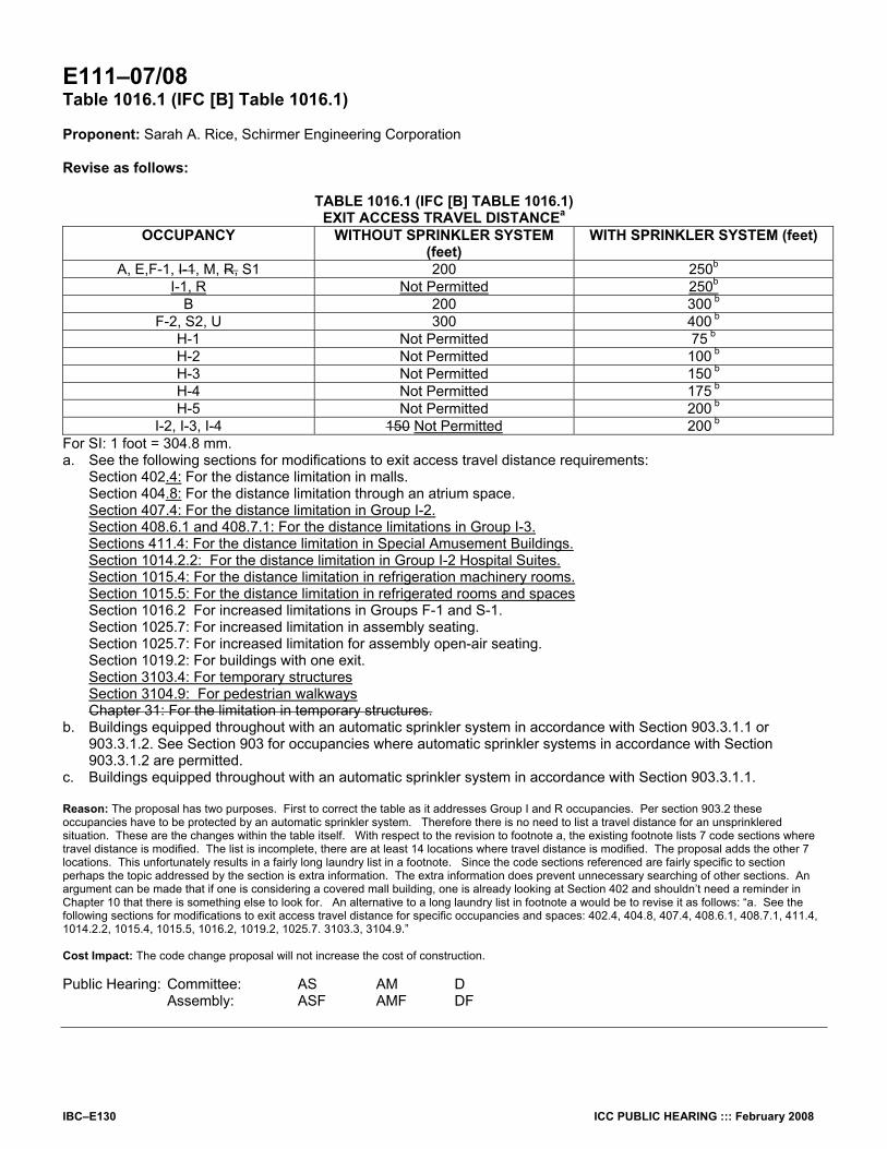
IBC–E130 ICC PUBLIC HEARING ::: February 2008
E111–07/08 Table 1016.1 (IFC [B] Table 1016.1) Proponent: Sarah A. Rice, Schirmer Engineering Corporation Revise as follows:
TABLE 1016.1 (IFC [B] TABLE 1016.1) EXIT ACCESS TRAVEL DISTANCEa
OCCUPANCY WITHOUT SPRINKLER SYSTEM (feet)
WITH SPRINKLER SYSTEM (feet)
A, E,F-1, I-1, M, R, S1 200 250b
I-1, R Not Permitted 250b
B 200 300 b F-2, S2, U 300 400 b
H-1 Not Permitted 75 b H-2 Not Permitted 100 b H-3 Not Permitted 150 b H-4 Not Permitted 175 b H-5 Not Permitted 200 b
I-2, I-3, I-4 150 Not Permitted 200 b For SI: 1 foot = 304.8 mm. a. See the following sections for modifications to exit access travel distance requirements:
Section 402.4: For the distance limitation in malls. Section 404.8: For the distance limitation through an atrium space. Section 407.4: For the distance limitation in Group I-2. Section 408.6.1 and 408.7.1: For the distance limitations in Group I-3. Sections 411.4: For the distance limitation in Special Amusement Buildings. Section 1014.2.2: For the distance limitation in Group I-2 Hospital Suites. Section 1015.4: For the distance limitation in refrigeration machinery rooms. Section 1015.5: For the distance limitation in refrigerated rooms and spaces Section 1016.2 For increased limitations in Groups F-1 and S-1. Section 1025.7: For increased limitation in assembly seating. Section 1025.7: For increased limitation for assembly open-air seating. Section 1019.2: For buildings with one exit. Section 3103.4: For temporary structures Section 3104.9: For pedestrian walkways Chapter 31: For the limitation in temporary structures.
b. Buildings equipped throughout with an automatic sprinkler system in accordance with Section 903.3.1.1 or 903.3.1.2. See Section 903 for occupancies where automatic sprinkler systems in accordance with Section 903.3.1.2 are permitted.
c. Buildings equipped throughout with an automatic sprinkler system in accordance with Section 903.3.1.1. Reason: The proposal has two purposes. First to correct the table as it addresses Group I and R occupancies. Per section 903.2 these occupancies have to be protected by an automatic sprinkler system. Therefore there is no need to list a travel distance for an unsprinklered situation. These are the changes within the table itself. With respect to the revision to footnote a, the existing footnote lists 7 code sections where travel distance is modified. The list is incomplete, there are at least 14 locations where travel distance is modified. The proposal adds the other 7 locations. This unfortunately results in a fairly long laundry list in a footnote. Since the code sections referenced are fairly specific to section perhaps the topic addressed by the section is extra information. The extra information does prevent unnecessary searching of other sections. An argument can be made that if one is considering a covered mall building, one is already looking at Section 402 and shouldn’t need a reminder in Chapter 10 that there is something else to look for. An alternative to a long laundry list in footnote a would be to revise it as follows: “a. See the following sections for modifications to exit access travel distance for specific occupancies and spaces: 402.4, 404.8, 407.4, 408.6.1, 408.7.1, 411.4, 1014.2.2, 1015.4, 1015.5, 1016.2, 1019.2, 1025.7. 3103.3, 3104.9.” Cost Impact: The code change proposal will not increase the cost of construction. Public Hearing: Committee: AS AM D Assembly: ASF AMF DF
ICC PUBLIC HEARING ::: February 2008 IBC–E131
E112–07/08 1016.2 [IFC [B] 1016.2) Proponent: Rick Thornberry, PE, The Code Consortium, Inc., representing AAMA Smoke Vent Task Group Revise as follows: 1016.2 (IFC [B] 1016.2) Roof Smoke and heat vent increase. In buildings that are one story in height, equipped with automatic heat and smoke and heat roof vents complying with Section 910 and equipped throughout with an automatic sprinkler system in accordance with Section 903.3.1.1, the maximum exit access travel distance shall be 400 feet (122 m) for occupancies in Group F-1 or S-1. Reason: Editorial. Cost Impact: The code change proposal will not increase the cost of construction. Public Hearing: Committee: AS AM D Assembly: ASF AMF DF
E113–07/08 1016.2 (IFC [B] 1016.2) Proponent: Richard Schulte, Schulte & Associates Revise as follows: 1016.2 (IFC [B] 1016.2) Roof vent increase. In buildings that are one story in height, equipped with automatic heat and smoke roof vents complying with Section 910 and equipped throughout with an automatic sprinkler system in accordance with Section 903.3.1.1, the maximum exit access travel distance shall be 400 feet (122 m) for occupancies in Group F-1 or S-1. Reason: The purpose of this proposal is to allow an increase in travel distance to 400 feet (from 250 feet) in single story sprinklered buildings which contain Group F-1 and S-1 occupancies without automatic smoke and heat vents being provided. For more than 20 years, an exception has been included in the model building codes used in the United States which permits an increase in travel distance to 400 feet in single-story Group F-1 and S-1 occupancies protected by a sprinkler system and provided with automatic smoke and heat vents. This exception has been based upon the assumption that the automatic smoke and heat vents would operate and vent heat and smoke from the building, thus increasing the time that occupants have to evacuate the building. Since the allowable travel distance is the means by which the code limits evacuation time, an increase in the time available for evacuation translates into an increase in the distance which can be safely traveled during an evacuation. Hence, an increased travel distance is permitted when a building containing a Group F-1 or S-1 occupancy is provided with automatic smoke and heat vents and sprinkler protection. While the provision which permits an increase in allowable travel distance when automatic smoke and heat vents are provided appears to be logical, fire tests utilizing a combination of standard spray sprinklers and fusible link-activated smoke and heat (roof) vents conducted at Underwriters Laboratories (UL) in 1997 and 1998 clearly demonstrated that operating sprinklers interfere with the opening of roof vents. The following are quotes from the report of the tests at UL, “Sprinkler, Smoke & Heat Vent, Draft Curtain Interaction -- Large Scale Experiments and Model Development”, dated September 1998. (The report is referred to as NISTIR 6196-1.)
“It had become clear by this time in the project that the vents were unlikely to open when the fire was ignited more than about 4.6 m (15 ft) away.” (Page 54, NISTIR 6196-1) “. . . .it appears from the data below that the sprinkler spray influenced the thermal response characteristics of this particular vent, and it is believed that sprinklers could have a similar influence on similar vent designs.” (Page 64, NISTIR 6196-1) “Six other tests were performed with the fire at this distance from the vent when the vent was equipped with a fusible link, and in none of these tests did the vent open. . . .Examination of the near-ceiling temperatures from all the tests indicates that sprinklers of this type [standard spray sprinklers] have a significant cooling effect, and this will certainly have an effect on thermally-responsive, independently-controlled vents.” (Page 64, NISTIR 6196-1) “In Plastic Test P-2, the fire was ignited directly under a vent. In the experiment, flames reached the top of the central array at about 65 s and the vent cavity at about 70 s. The first sprinkler activated at 100 s. The vent did not open at any time during the 30 min test even though another vent 6 m (20 ft) to the west of the unopened vent opened at 6:04.” Page 64, NISTIR 6196-1) “This data, along with the plunge tunnel measurements reported in Section 3.1.4, suggests that the fusible link reached its activation temper-ature before or at about the same time as the first sprinkler activated, but the link did not fuse. It is not clear whether the link did not fuse be-cause it was cooled directly by water drawn upwards into the vent cavity, or whether the sprinkler spray simply cooled the rising smoke plume enough to prevent the link from fusing. In any event, this phenomenon deserves further study.” (Page 64, NISTIR 6196-1) “The mass flow rates [through the vents] for Test I-10 and P-5 are relatively low compared with the theoretical maximum because the near-ceiling gas temperatures are greatly reduced by the sprinklers.” (Page 100, NISTIR 6196-1) “The significant cooling effect of sprinkler sprays on the near-ceiling gas flow often prevented the automatic operation of vents. This conclusion is based on thermocouple measurements within the vent cavity, the presence of drips of solder on the fusible links recovered from unopened vents, and several tests where vents remote from the fire and the sprinkler spray activated. In one cartoned plastic commodity experiment, a vent did not open when the fire was ignited directly beneath it.” (Page 101, NISTIR 6196-1)

IBC–E132 ICC PUBLIC HEARING ::: February 2008
The following are quotes from Dr. Craig Beyler, Hughes Associates, Inc. (a consultant to the AAMA Smoke Vent Task Group) regarding the operation of smoke and heat (roof) vents in buildings protected by a sprinkler system: “The experimental studies have shown that . . . . .current design practices are likely to limit the number of vents operated to one and vents may in fact not operate at all in very successful sprinkler operations.” (Page 1, “Interaction of Sprinklers with Smoke and Heat Vents”) “Not only is the fear of early operation not founded, current design practice will likely lead to 0-1 vents operating” (Page 61, “Sprinkler/Vent Interactions-What people think, what we know, and what we don’t.”) Given the above, it can be concluded that smoke and heat (roof) vents do not actually operate as expected in buildings protected by a sprinkler
system. Hence, the logic behind the increase in travel distance to 400 feet is flawed. For the last 20 years (or more), the increase in travel distance to 400 feet has been considered acceptable when sprinkler protection and automatic roof vents are provided. If automatic smoke and heat vents will not operate in sprinklered buildings, then it can be concluded that it is actually the sprinkler protection provided in the building that makes this increase in the travel distance limitation acceptable. Hence, it is logical that an increase in travel distance should be permitted in one story buildings containing Group F-1 or S-1 occupancies solely based upon the protection provided by sprinklers. In other words, automatic smoke and heat vents provide no additional protection for occupants evacuating a storage or industrial building and it is the sprinkler protection (along with the size of the building) which is providing all of the protection necessary to permit an extended egress travel distance. Bibliography: 1. “Sprinkler, Smoke & Heat Vent, Draft Curtain Interaction -- Large Scale Experiments and Model Development” (NISTIR 6196-1), Kevin B.
McGrattan, Anthony Hamins, David Stroup, September 1998. http://www.fire.nist.gov/bfrlpubs/fire98/PDF/f98069.pdf
2. “Interaction of Sprinklers with Smoke and Heat Vents”, Craig L. Beyler and Leonard Y. Cooper, February 1999. http://www.haifire.com/publications/Paper21.pdf 3. “Sprinkler/Vent Interactions-What people think, what we know, and what we don’t.”, Dr. Craig Beyler, Hughes Associates, Inc. (undated
presentation). http://www.haifire.com/presentations/Sprinkler%20Vent%20Interactions%20-%20NFPA%202000.pdf
Cost Impact: The code change proposal will not increase the cost of construction. Public Hearing: Committee: AS AM D Assembly: ASF AMF DF
E114–07/08 Table 1016.1, 1016.2 (IFC [B] Table 1016.1, [B] 1016.2); IFC 910.2.3 (IBC [F] 910.2.3) Proponent: Richard Schulte, Schulte & Associates 1. Revise IBC as follows:
TABLE 1016.1 (IFC [B] TABLE 1016.1) EXIT ACCESS TRAVEL DISTANCE
(No change to table entries) For SI: 1 foot = 304.8 mm. a. See the following sections for modifications to exit access travel distance requirements:
Section 402: For the distance limitation in malls. Section 404: For the distance limitation through an atrium space. Section 1016.2 For increased limitations in Groups F-1 and S-1. Section 1025.7: For increased limitation in assembly seating. Section 1025.7: For increased limitation for assembly open-air seating. Section 1019.2: For buildings with one exit. Chapter 31: For the limitation in temporary structures.
b. Buildings equipped throughout with an automatic sprinkler system in accordance with Section 903.3.1.1 or 903.3.1.2. See Section 903 for occupancies where automatic sprinkler systems in accordance with Section 903.3.1.2 are permitted.
c. Buildings equipped throughout with an automatic sprinkler system in accordance with Section 903.3.1.1. 1016.2 (IFC [B] 1016.2) Roof vent increase. In buildings that are one story in height, equipped with automatic heat and smoke roof vents complying with Section 910 and equipped throughout with an automatic sprinkler system in accordance with Section 903.1.1, the maximum exit access travel distance shall be 400 feet (122 m) for occupancies in Group F-1 or S-1. 2. Revise IFC as follows: IFC 910.2.3 (IBC [F] 910.2.3 Exit access travel distance increase. Buildings and portions thereof used as a Group F-1 or S-1 occupancy where the maximum exit access travel distance is increased in accordance with Section 1016.2.

ICC PUBLIC HEARING ::: February 2008 IBC–E133
Reason: The purpose of this code change proposal is to delete the provision which allows an increase in travel distance to 400 feet in one story Group F-1 and S-1 occupancies protected by a sprinkler system and provided with smoke and heat (roof) vents. At present, the IBC permits travel distance to be increased from 200 feet to 250 feet in Group F-1 and S-1 occupancies when sprinkler protection is provided. Section 1016.2 allows an additional 150 feet of travel distance in Group F-1 and S-1 occupancies above and beyond that permitted when sprinkler protection is provided when smoke and heat (roof) vents are also provided. While smoke and heat (roof) vents by themselves will automatically vent smoke and heat generated by a fire in an unsprinklered one story building, there is serious doubt whether or not smoke and heat (roof) vents actually perform their intended function in buildings protected throughout by a sprinkler system. Fire tests utilizing a combination of standard spray sprinklers and fusible link-activated smoke and heat (roof) vents conducted at Underwriters Laboratories (UL) in 1997 and 1998 clearly demonstrated that operating sprinklers interfere with the opening of roof vents. The following are quotes from the report of the tests at UL, “Sprinkler, Smoke & Heat Vent, Draft Curtain Interaction -- Large Scale Experiments and Model Development”, dated September 1998. (The report is referred to as NISTIR 6196-1.)
“It had become clear by this time in the project that the vents were unlikely to open when the fire was ignited more than about 4.6 m (15 ft) away.” (Page 54, NISTIR 6196-1) “. . . .it appears from the data below that the sprinkler spray influenced the thermal response characteristics of this particular vent, and it is believed that sprinklers could have a similar influence on similar vent designs.” (Page 64, NISTIR 6196-1) “Six other tests were performed with the fire at this distance from the vent when the vent was equipped with a fusible link, and in none of these tests did the vent open. . . Examination of the near-ceiling temperatures from all the tests indicates that sprinklers of this type [standard spray sprinklers] have a significant cooling effect, and this will certainly have an effect on thermally-responsive, independently-controlled vents.” (Page 64, NISTIR 6196-1) “In Plastic Test P-2, the fire was ignited directly under a vent. In the experiment, flames reached the top of the central array at about 65 s and the vent cavity at about 70 s. The first sprinkler activated at 100 s. The vent did not open at any time during the 30 min test even though another vent 6 m (20 ft) to the west of the unopened vent opened at 6:04.” Page 64, NISTIR 6196-1) “This data, along with the plunge tunnel measurements reported in Section 3.1.4, suggests that the fusible link reached its activation tem-perature before or at about the same time as the first sprinkler activated, but the link did not fuse. It is not clear whether the link did not fuse because it was cooled directly by water drawn upwards into the vent cavity, or whether the sprinkler spray simply cooled the rising smoke plume enough to prevent the link from fusing. In any event, this phenomenon deserves further study.” (Page 64, NISTIR 6196-1) “The mass flow rates [through the vents] for Test I-10 and P-5 are relatively low compared with the theoretical maximum because the near-ceiling gas temperatures are greatly reduced by the sprinklers.” (Page 100, NISTIR 6196-1) “The significant cooling effect of sprinkler sprays on the near-ceiling gas flow often prevented the automatic operation of vents. This conclusion is based on thermocouple measurements within the vent cavity, the presence of drips of solder on the fusible links recovered from unopened vents, and several tests where vents remote from the fire and the sprinkler spray activated. In one cartoned plastic commodity experiment, a vent did not open when the fire was ignited directly beneath it.” (Page 101, NISTIR 6196-1)
NFPA 204 also clearly indicates that operating sprinklers will reduce the venting rate through any vents which do open due to the reduction of temperature in the vicinity of the vent caused by operating sprinklers. The following is an excerpt from the 2002 edition of NFPA 204:
“A.4.4.3 Mass flow through a vent is governed mainly by the vent area and the depth of the smoke layer and its temperature. Venting becomes more effective with smoke temperature differentials between ambient temperature and an upper layer of approximately 110°C [198oF] or higher. Where temperature differences of less than 110°C [198oF] are expected, vent flows might be reduced significantly. . . .”
The following are quotes from Dr. Craig Beyler, Hughes Associates, Inc. regarding the operation of smoke and heat (roof) vents in buildings protected by a sprinkler system:
“The experimental studies have shown that . . . . .current design practices are likely to limit the number of vents operated to one and vents may in fact not operate at all in very successful sprinkler operations.” (Page 1, “Interaction of Sprinklers with Smoke and Heat Vents”) Not only is the fear of early operation not founded, current design practice will likely lead to 0-1 vents operating” (“Page 61,” “Sprinkler/Vent Interactions-What people think, what we know, and what we don’t.”) “Eliminates Need for Manual Venting? No” (Page 42, ““Sprinkler/Vent Interactions-What people think, what we know, and what we don’t.”) “Revised design methods for early operation of vents are needed” (Page 61, “Sprinkler/Vent Interactions-What people think, what we know, and what we don’t.”)
Given the above, it can be concluded that smoke and heat (roof) vents do not actually operate as expected in buildings protected by a sprinkler system. Based upon this, it can be concluded that there is no technical basis for permitting an increase in travel distance of 150 feet beyond the travel distance permitted for Group F-1 and S-1 occupancies protected by a sprinkler system when smoke and heat (roof) vents are provided. Bibliography 1. “Sprinkler, Smoke & Heat Vent, Draft Curtain Interaction -- Large Scale Experiments and Model Development” (NISTIR 6196-1), Kevin B.
McGrattan, Anthony Hamins, David Stroup, September 1998. http://www.fire.nist.gov/bfrlpubs/fire98/PDF/f98069.pdf
2. “Interaction of Sprinklers with Smoke and Heat Vents”, Craig L. Beyler and Leonard Y. Cooper, February 1999. http://www.haifire.com/publications/Paper21.pdf 3. “Sprinkler/Vent Interactions-What people think, what we know, and what we don’t.”, Dr. Craig Beyler, Hughes Associates, Inc. (undated
(presentation). http://www.haifire.com/presentations/Sprinkler%20Vent%20Interactions%20-%20NFPA%202000.pdf
4. NFPA 204, Standard for Smoke and Heat Venting (2002 edition). Cost Impact: The code change proposal will increase the cost of construction. Public Hearing: Committee: AS AM D Assembly: ASF AMF DF

IBC–E134 ICC PUBLIC HEARING ::: February 2008
E115–07/08 1016.3 (New) (IFC [B] 1016.3 (New)) Proponent: Robert J. Davidson, Davidson Code Concepts, LLC, representing himself Add new text as follows: 1016.3 (IFC [B] 1016.3) Early suppression fast-response (ESFR) sprinklers increase. In buildings equipped with an automatic sprinkler system in accordance with Section 903.3.1.1, for areas not required to have smoke and heat vents as provided by section 910.1, Exception 2, the maximum exit access travel distance shall be 400 feet (122 m) for occupancies in Group F-1 or S provided:
1. The building is provided with a fire alarm signaling system activated by sprinkler water-flow devices installed in accordance with Section 907; and,
2. An engineering analysis is provided that documents that the intended occupants will have safely exited the building before the height of the lowest horizontal surface of the accumulating smoke layer is less than 6 feet (1829 mm) above any walking surface that forms a portion of a required egress system within the ESFR protected area based upon the configuration of the fuel load expected to be present.
(Renumber subsequent section) Reason: In the 2003 editions of the IBC and the IFC recognition was provided for the effectiveness of early suppression fast-response (ESFR) sprinklers by eliminating the requirement for smoke and heat vents for areas protected by those systems. The change was made to the 2003 editions of both codes for the purpose of balancing the application of the newer ESFR technology against the existing requirement for the smoke and heat vents together with the IFC committees concern with providing for firefighter safety. This proposal provides correlation between the ESFR exception to Section 910.1 concerning smoke and heat vents and the increased travel distance allowance of Section 1016.2. The configuration of fuel loads and the egress capabilities of the intended occupants varies from occupancy to occupancy and cannot be addressed by a one size fits all exception. By requiring an engineering analysis to be submitted life safety needs will be met by balancing the egress capabilities, (time needed to exit), of the intended occupants against the smoke layer generation of the fuel load and fuel configuration expected to be present. The language relating to the 6 foot height of the smoke layer correlates with existing Section 909.8.1 which is the level chosen to meet the tenable environment for evacuation requirements found in existing Section 909.1 concerning smoke control systems. When using engineering analysis to model egress times of occupants and how long occupant egress takes, the model is based upon the occupants knowing they are supposed to be moving towards an exit at a defined reference point in time. The only effective way to provide for this ‘knowledge’ on the part of the occupants is to require the installation of alarm notification appliances in accordance with Chapter 9, Fire Protection Systems and its’ referenced standard, NFPA 72, The National Fire Alarm Code. This proposal also meets the intent of the IBC and IFC to provide for “…safety to firefighters…” by tying the exception to the use of the ESFR sprinklers. The IFC committee stated that they accepted ESFR systems as an exception to the installation of smoke and heat vents because the capability of the ESFR systems to quickly suppress and possibly extinguish fires will greatly reduce the amount of smoke and heat generated. This is important since the lengthening of the travel distance allowed for egress of occupants will correlate directly with the lengthening of the distance firefighters might have to travel in entering the fire structure for the purpose of search and rescue and fire extinguishment, i.e., increases their exposure to risk. Cost Impact: The code change proposal will not increase the cost of construction. Public Hearing: Committee: AS AM D Assembly: ASF AMF DF

ICC PUBLIC HEARING ::: February 2008 IBC–E135
E116–07/08 Table 1017.1 (IFC [B] Table 1017.1) Proponent: Laura Blaul, Orange County Fire Authority, representing California Fire Chiefs Association Revise table as follows:
TABLE 1017.1 (IFC [B] Table 1017.1) CORRIDOR FIRE-RESISTANCE RATING
REQUIRED FIRE-RESISTANCE RATING (HOURS)
OCCUPANCY OCCUPANT LOAD SERVED BY CORRIDOR Without sprinkler
system With sprinkler
system in areas without
interrupted water supplyc
With sprinkler system in areas with interrupted water supplyc
H-1, H-2, H-3 All Not Permitted 1 1 H-4, H-5 Greater than 30 Not Permitted 1 1 A, B, E, F, M, S, U Greater than 30 1 0 1 R Greater than 10 1 0.5 1 I-2a, I-4 All Not Permitted 0 1 I-1, I-3 All Not Permitted 1b 1b
a. For requirements for occupancies in Group I-2, see Section 407.3. b. For a reduction in the fire-resistance rating for occupancies in Group I-3, see Section 408.7. c. Buildings equipped throughout with an automatic sprinkler system in accordance with Section 903.3.1.1 or
903.3.1.2 where allowed. Reason: The purpose of this code change is to reduce the reliance of firefighters, and the community on adequate water supply to help prevent conflagration where the water supply may be interrupted by natural disaster or water system operation issues in the event of an emergency. This proposed amendment eliminates the automatic sprinkler system trade-off for corridors and reinstates the one hour fire resistance rating requirement for corridors in all occupancies. The 2006 International Building Code allows the use of non-fire resistance rated corridors (less than 1-hour fire resistance rating) to a much greater extent than the 1997 Uniform Building Code (UBC) currently adopted by California. In many cases the required 1-hour fire resistance rating for corridors is traded-off for the installation of an automatic sprinkler system. We do not believe that such trade-offs are appropriate where life safety is concerned. In such cases, it is advantageous and desirable to maintain the built-in passive fire resistant protection, as well as to provide the active automatic sprinkler system protection, where life safety is involved. In our opinion, trade-offs are entirely inappropriate where life safety is concerned. We believe that a balanced approach should be used to assure that the appropriate level of life safety will be provided to the occupants of the building who must rely upon the corridors to exit the building. A secondary benefit of 1-hour fire resistance rated corridors is that they also assist fire fighters in doing their job by providing a protected means of access to the interior of the building where they can perform their search and rescue missions, as well as fire fighting operations, in relative safety. Fire resistance rated corridors can provide fire fighters with additional time to do their jobs more effectively and safely. We strongly believe that sprinkler trade-offs should not be allowed for means of egress components. In California we are especially concerned because of the high probability of severe earthquakes occurring which can knock out the water supply to the sprinkler system. At present, neither the UBC nor the IBC allow sprinkler trade-offs for the fire resistance ratings required for exit stair enclosures, horizontal exits, and exit passageways. So why should sprinkler trade-offs be allowed for the 1-hour fire resistance rating of corridors which provide a protected egress path giving access to these exit elements? Furthermore, other sprinkler trade-offs related to the means of egress in buildings have already been provided for in the IBC. For example, travel distance is allowed to be increased where automatic sprinkler systems are provided. The separation of exits (remoteness) is also allowed to be reduced where automatic sprinkler systems are installed. Interior finish requirements are relaxed within corridors where Class C interior finish can be used in lieu of Class B interior finish and Class B interior finish can be used where Class A interior finish would otherwise be required if not for the installation of automatic sprinklers. And in certain occupancies dead end corridors are allowed to be increased in length by as much as 150%, i.e. from 20 feet to 50 feet, where automatic sprinkler systems are provided. We are concerned that the compounding effect of sprinkler trade-offs could lead to greater risk to the life safety of the building occupants, especially if combined with a reduction in or the elimination of the 1-hour fire resistance rating for corridors providing access to the exits or the exit stairs. Too much reliance on automatic sprinkler systems may not be wise where life safety is a key consideration. We strongly believe that a balanced approach to fire and life safety in buildings should be provided to greatly enhance the probability that the intended level of fire and life safety prescribed by the building code will be provided when a fire occurs, even if something should go wrong. We acknowledge that automatic sprinkler systems are an important fire protection tool, but they are not infallible. Like any mechanical system, they are subject to failure. In fact, a recent statistical analysis of automatic sprinkler system performance conducted by the NFPA has concluded that automatic sprinkler systems fail to activate in at least 1 out of every 6 fires that occur in sprinklered buildings. In our opinion such a level of performance does not justify trading-off built-in fire resistant protection for the means of egress in buildings where the occupant’s lives are at risk in a fire emergency. A balanced design approach of providing built-in fire resistive protection in conjunction with automatic sprinkler protection, in our opinion, will go a long way toward assuring that the level of fire and life safety intended by the building code will be delivered during a fire emergency. A code change that is being heard by the Fire Safety committee will include the definition for areas of interrupted water supply as follows:
AREAS OF INTERRUPTED WATER SUPPLY. Regions or areas where the water supply available for fire suppression is subject to extended periods of failure due to natural disaster or other factors, as determined by the building official to meet any of the following conditions:

IBC–E136 ICC PUBLIC HEARING ::: February 2008
1. Areas, regions or geologic features where the 0.2 second spectral response acceleration in Figure 1613.5(1) is 150% or greater; or alluvial valleys located between or adjacent to geologic features or areas where the 0.2 second spectral response acceleration in Figure 1613.5(1) is 150% or greater.
2. Flood hazard areas defined in Section 1612.3. 3. Hurricane-prone regions defined in Section 1609.2. 4. Areas where the water system is not deemed to be operational or reliable in the event of an emergency as determined by
the authority having jurisdiction.
Cost Impact: This code change proposal will increase the cost of construction in certain geographic areas or regions as defined. Analysis: The committee is requested to state its intent regarding this code change proposal should the definition of “AREAS OF INTERRUPTED WATER SUPPLY. “ given in the code change proposal for the IBC-Fire Safety committee be disapproved. Public Hearing: Committee: AS AM D Assembly: ASF AMF DF
E117–07/08 Table 1017.1 (IFC [B] Table 1017.1) Proponent: Greg Lake, Sacramento Metropolitan Fire District, representing California Fire Chiefs Association (Cal Chiefs); Thomas S. Zaremba, Roetzel & Andress, representing Pilkington Fire Glass North America Revise table as follows:
TABLE 1017.1 (IFC [B] TABLE 1017.1) CORRIDOR FIRE-RESISTANCE RATING
REQUIRED FIRE-RESISTANCE RATING (hours) OCCUPANCY OCCUPANT LOAD SERVED BY CORRIDOR Without sprinkler system With sprinkler systemc
H-1, H-2, H-3 All Not Permitted 1 H-4, H-5 Greater than 30 Not Permitted 1
A,B, E, F, M, S, U Greater than 30 1 0 E Greater than 30 1 1 R Greater than 10 Not Permitted 0.5
I-2a, I-4 All Not Permitted 0 I-1, I-3 All Not Permitted 1b
a. For requirements for occupancies in Group I-2, see Section 407.3. b. For a reduction in the fire-resistance rating for occupancies in Group I-3, see Section 408.7 c. Buildings equipped throughout with an automatic sprinkler system in accordance with Section 903.3.1.1 or 903.1.2
where allowed. Reason: Lake - This code change proposal will require all corridors serving an occupant load greater than 30 in Group E educational occupancies to have a 1-hour fire-resistance rating except as allowed by Exception 1 to Section 1017.1.
Exception 1 to Section 1017.1 is a legitimate exception for the one-hour corridor fire resistance rating requirement since it requires every classroom to have at least one door directly to the exterior and that any rooms used for assembly purposes have at least ½ of the required means of egress directly to the exterior as well. Under those conditions, there is no need for the students and other occupants to rely on exiting the building via the corridors since they can go directly to the exterior and move away from the building to a safe area. However, if that is not the case, then the students, teachers, and other occupants of the educational occupancy must rely on the corridor system to exit safely from the building. In that case the paths of travel to get out of the building are restricted and they may be exposed to the room of fire origin while trying to evacuate. Certainly, the basis for one-hour fire resistive protection for corridors when the occupant load exceeds 30 is to provide for a reasonable level of protection for the occupants as they exit the building without having them unduly exposed to a fire condition which may impede their egress.
Presently, the International Building Code (IBC) allows the 1-hour fire-resistance rated corridor to be omitted where the building is protected by an automatic sprinkler system. We don’t believe that such a trade-off is appropriate, especially in an educational occupancy where there are large numbers of children at relatively high density who are placed at risk in a fire situation. We believe that a balanced design approach to providing life safety in educational occupancies is prudent so that the 1-hour fire-resistance rated corridors can work in conjunction with the automatic sprinkler system to assure the level of life safety for the building’s occupants intended by the code.
Although sprinklers are a valuable fire protection tool, they are not infallible nor can they be assured of providing the necessary degree of protection to allow a 1-hour reduction in fire-resistance for the corridors. A recent analysis of NFPA sprinkler system performance data by William E. Koffel, P.E. of Koffel Associates has indicated that sprinklers failed to perform satisfactorily in at least 1 out of every 9 fires that occur in sprinklered buildings. We believe that such a performance level does not justify deleting or trading-off the 1-hour fire-resistance rating for corridors that provide a protected means of egress for school children in Group E educational occupancies.
We do not believe that such trade-offs are appropriate where life safety is concerned. In such cases, it is advantageous and desirable to maintain the built-in passive fire resistant protection, as well as to provide the active automatic sprinkler system protection, where life safety is involved. In our opinion, trade-offs are entirely inappropriate where life safety is concerned. We believe that a balanced approach should be used to assure that the appropriate level of life safety will be provided to the occupants of the building who must rely upon the corridors to exit the building.
A secondary benefit of 1-hour fire resistance rated corridors is that they also assist fire fighters in doing their job by providing a protected means of access to the interior of the building where they can perform their search and rescue missions, as well as fire fighting operations, in relative safety. Fire resistance rated corridors can provide fire fighters with additional time to do their jobs more effectively and safely.

ICC PUBLIC HEARING ::: February 2008 IBC–E137
We strongly believe that sprinkler trade-offs should not be allowed for means of egress components. In California we are especially concerned because of the high probability of severe earthquakes occurring which can knock out the water supply to the sprinkler system. At present, the IBC does not allow sprinkler trade-offs for the fire resistance ratings required for exit stair enclosures, horizontal exits, and exit passageways. So why should sprinkler trade-offs be allowed for the 1-hour fire resistance rating of corridors which provide a protected egress path giving access to these exit elements?
Furthermore, other sprinkler trade-offs related to the means of egress in buildings have already been provided for in the IBC. For example, travel distance is allowed to be increased from 200 feet to 250 feet where automatic sprinkler systems are provided. The separation of exits (remoteness) is also allowed to be reduced where automatic sprinkler systems are installed. Interior finish requirements are relaxed within corridors where Class C interior finish can be used in lieu of Class B interior finish which would otherwise be required if not for the installation of automatic sprinklers.
We are concerned that the compounding effect of sprinkler trade-offs could lead to greater risk to the life safety of the building occupants, especially if combined with a reduction in or the elimination of the 1-hour fire resistance rating for corridors providing access to the exits or the exit stairs. Too much reliance on automatic sprinkler systems may not be wise where life safety is a key consideration. We strongly believe that a balanced approach to fire and life safety in buildings should be provided to greatly enhance the probability that the intended level of fire and life safety prescribed by the building code will be provided when a fire occurs, even if something should go wrong.
In conclusion it should also be noted that our Public Comment #1 to Code Change Proposal E127-06-07 which attempted to do exactly what this code change proposal is doing for corridors in Group E occupancies was successful in overturning the Committee’s recommendation for disapproval at the ICC Final Action Hearings in Rochester, NY. Unfortunately, we were not able to achieve the necessary 2/3 majority vote for an approval. Because of that membership vote, we were encouraged to submit this code change proposal focusing on Group E occupancies. Zaremba: The purpose of this proposal is to provide a redundant level of life-safety to children gathered in relatively high densities in educational occupancies. Currently, the code eliminates any required fire-resistance rating for corridors in E occupancies if a sprinkler system is in place. In the event of fire and a sprinkler system failure for any reason, (whether a loss of water; someone inadvertently closes the wrong valve, rendering the system inoperable; an explosion damages the piping; the fire starts in a non-sprinklered part of the building; etc. etc) redundancy will be necessary to ensure the safe evacuation of frightened children. The risk and need for redundancy are heightened if the school is multi-storied. Cost Impact: The code change proposal will increase the cost of construction. Public Hearing: Committee: AS AM D Assembly: ASF AMF DF
E118–07/08 Table 1017.1 (IFC [B] Table 1017.1) Proponent: Greg Lake, Sacramento Metropolitan Fire District, representing California Fire Chiefs Association (Cal Chiefs) Revise table as follows:
TABLE 1017.1 (IFC [B] TABLE 1017.1) CORRIDOR FIRE-RESISTANCE RATING
REQUIRED FIRE-RESISTANCE RATING (hours) OCCUPANCY OCCUPANT LOAD SERVED BY CORRIDOR Without sprinkler system With sprinkler systemc
H-1, H-2, H-3 All Not Permitted 1 H-4, H-5 Greater than 30 Not Permitted 1
A,B, E, F, M, S, U Greater than 30 1 0 R Greater than 10 Not Permitted 0.5 1
1-2a, I-4 All Not Permitted 0 I-1, I-3 All Not Permitted 1b
a. For requirements for occupancies in Group I-2, see Section 407.3. b. For a reduction in the fire-resistance rating for occupancies in Group I-3, see Section 408.7 c. Buildings equipped throughout with an automatic sprinkler system in accordance with Section 903.3.1.1 or 903.1.2
where allowed. Reason: We have submitted this code change proposal to focus on the Group R occupancies for requiring all corridors serving an occupant load greater than 10 to have a minimum fire-resistance rating of 1 hour, even where the building is sprinklered. We believe that the 1 hour fire-resistance rating required for a corridor in Group R occupancies should not be reduced to a ½ hour (30 minute) fire-resistance rating with the installation of an automatic sprinkler system, especially when that sprinkler system need only comply with NFPA 13R which allows for partial sprinklering of the building. We should point out that currently the code will not allow the required separation between adjacent Group R occupancies or sleeping units to be reduced below 1 hour even when an automatic sprinkler system is installed except for buildings of Types IIB, IIIB, and VB construction. But then the fire-resistance rating is allowed to be reduced to ½ hour only if the sprinkler system in installed in accordance with NFPA 13 and not NFPA 13R. Shouldn’t corridors for these Group R occupancies have at least the same level of protection as the separations required between the individual occupied spaces in these occupancies?
Furthermore, it becomes difficult to enforce code requirements for ½ hour fire-resistance rated fire partitions since there are no penetration or joint protection systems listed for ½ hour wall assemblies nor are there any fire dampers listed for such wall assemblies. On top of that the ASTM E119 fire-resistance test for walls does not require the hose stream test for any wall that has a fire-resistance rating of less than 1 hour. So the corridor walls can be a very flimsy construction which could not even hold up to a hose stream test conducted after the wall would have been burned for ½ hour to satisfy the requirements in ASTM E119 for a 1-hour wall.

IBC–E138 ICC PUBLIC HEARING ::: February 2008
There are very few wall assemblies that have been listed for ½ hour. One of those is UL U319 which only requires one layer of 3/8 inch thick Type X gypsum wallboard on each side of studs. Otherwise, a calculated fire-resistance design could be used in accordance with Section 721.6. Such ½ hour (30 minute) partitions could be constructed of 3/8 inch regular gypsum wallboard installed on both sides of wood studs at 16 inches on center or 15/32 inch plywood or 3/8 inch thick plywood with glass fiber insulation in the stud space (which would actually achieve a 40 minute fire-resistance rating). We don’t believe that these types of wall constructions provide adequate fire and smoke protection and structural integrity during a fire exposure condition, especially in the case where the automatic sprinkler system may fail to perform satisfactorily.
We are not aware of many projects where the corridor walls are actually constructed to meet the minimum ½ hour fire-resistance rating. It is just not practical since most projects only use one type of gypsum wallboard to stock the job in order to minimize confusion and improper installation using the wrong type or thickness. So for commercial jobs 5/8 inch Type X gypsum wallboard is generally used throughout the project. When a single layer of 5/8 inch Type X gypsum wallboard is installed on both sides of studs, it achieves a 1 hour fire-resistance rating. So it seems somewhat meaningless and not very cost effective to continue to allow the ½ hour trade-off for an NFPA 13R automatic sprinkler system in Group R occupancies.
We do not believe that such trade-offs are appropriate where life safety is concerned. In such cases, it is advantageous and desirable to maintain the built-in passive fire resistant protection, as well as to provide the active automatic sprinkler system protection, where life safety is involved. In our opinion, trade-offs are entirely inappropriate where life safety is concerned. We believe that a balanced approach should be used to assure that the appropriate level of life safety will be provided to the occupants of the building who must rely upon the corridors to exit the building.
A secondary benefit of 1-hour fire resistance rated corridors is that they also assist fire fighters in doing their job by providing a protected means of access to the interior of the building where they can perform their search and rescue missions, as well as fire fighting operations, in relative safety. Fire resistance rated corridors can provide fire fighters with additional time to do their jobs more effectively and safely.
We strongly believe that sprinkler trade-offs should not be allowed for means of egress components. In California we are especially concerned because of the high probability of severe earthquakes occurring which can knock out the water supply to the sprinkler system. At present, the IBC does not allow sprinkler trade-offs for the fire resistance ratings required for exit stair enclosures, horizontal exits, and exit passageways. So why should sprinkler trade-offs be allowed for the 1-hour fire resistance rating of corridors which provide a protected egress path giving access to these exit elements?
Furthermore, other sprinkler trade-offs related to the means of egress in buildings have already been provided for in the IBC. For example, travel distance is allowed to be increased from 200 feet to 250 feet where automatic sprinkler systems are provided. The separation of exits (remoteness) is also allowed to be reduced where automatic sprinkler systems are installed. Interior finish requirements are relaxed within corridors where Class C interior finish can be used in lieu of Class B interior finish which would otherwise be required if not for the installation of automatic sprinklers. And in Group R-2 occupancies the common path of travel is allowed to be increased in length by 67% from 75 feet to 125 feet where automatic sprinkler systems are provided.
We are concerned that the compounding effect of sprinkler trade-offs could lead to greater risk to the life safety of the building occupants, especially if combined with a reduction in or the elimination of the 1-hour fire resistance rating for corridors providing access to the exits or the exit stairs. Too much reliance on automatic sprinkler systems may not be wise where life safety is a key consideration. We strongly believe that a balanced approach to fire and life safety in buildings should be provided to greatly enhance the probability that the intended level of fire and life safety prescribed by the building code will be provided when a fire occurs, even if something should go wrong.
We acknowledge that automatic sprinkler systems are an important fire protection tool, but they are not infallible. Like any mechanical system, they are subject to failure. In fact, a recent statistical analysis of automatic sprinkler system performance conducted by the NFPA has concluded that automatic sprinkler systems fail to activate in at least 1 out of every 9 fires that occur in sprinklered buildings. In our opinion such a level of performance does not justify trading-off built-in fire resistant protection for the means of egress in buildings where the occupant’s lives are at risk in a fire emergency. A balanced design approach of providing built-in fire resistive protection in conjunction with automatic sprinkler protection, in our opinion, will go a long way toward assuring that the level of fire and life safety intended by the building code will be delivered during a fire emergency.
In conclusion it should also be noted that our Public Comment #2 to Code Change Proposal E127-06-07 which attempted to do exactly what this code change proposal is doing for corridors in Group R occupancies was successful in overturning the Committee’s recommendation for disapproval at the ICC Final Action Hearings in Rochester, NY. Unfortunately, we were not able to achieve the necessary 2/3 majority vote for an approval. Because of that membership vote, we were encouraged to submit this code change proposal focusing on Group R occupancies. Cost Impact: The code change proposal will increase the cost of construction. Public Hearing: Committee: AS AM D Assembly: ASF AMF DF
E119–07/08 Table 1017.1 (IFC [B] Table 1017.1) Proponent: Greg Lake, Sacramento Metropolitan Fire District, representing California Fire Chief’s Association (Cal Chiefs) Revise table as follows:
TABLE 1017.1 (IFC [B] TABLE 1017.1) CORRIDOR FIRE-RESISTANCE RATING
REQUIRED FIRE-RESISTANCE RATING (hours) OCCUPANCY OCCUPANT LOAD SERVED BY CORRIDOR Without sprinkler system With sprinkler systemc
H-1, H-2, H-3 All Not Permitted 1 H-4, H-5 Greater than 30 Not Permitted 1
A,B, E, F, M, S, U Greater than 30 1 0 R Greater than 10 Not Permitted 0.5
1-2a, I-4 All Not Permitted 0 1 I-1, I-3 All Not Permitted 1b

ICC PUBLIC HEARING ::: February 2008 IBC–E139
a. For requirements for occupancies in Group I-2, see Section 407.3. b. For a reduction in the fire-resistance rating for occupancies in Group I-3, see Section 408.7 c. Buildings equipped throughout with an automatic sprinkler system in accordance with Section 903.3.1.1 or 903.1.2
where allowed. Reason: We have submitted this code change proposal to focus on the Group I occupancies for requiring all corridors to have a minimum fire-resistance rating of 1 hour, even where the building is sprinklered. We believe that the 1 hour fire-resistance rating required for a corridor in Group I occupancies is appropriate due to the users of these types of facilities are often of limited mobility, restrained, or completely nonambulatory and relying on staff to exit. This type of exiting requires more time and a rated corridor with opening protection will provide that additional time.
Being dependent on staff alone for safe egress is not appropriate. It has been long understood that in an emergency situation the less we are dependent on human error the better. With the life safety features provided in the current code for these occupancies we are heavily dependent on staffing levels. There are very few states that have minimum staffing levels in hospitals, let alone residential facilities. The NFPA and Joint Commission on Healthcare Accrediation, both promote the RACE concept for staff to follow. RACE is Rescue, Alarm, Contain, Extinguish. We have seen many fires in these facilities where the staff is doing good to get the rescue accomplished on their own, remember these are not first responders, they are health care providers, training in this area is limited and they often find themselves having to move a patient twice their size. Training of this type in an I-4 is likely non-existent. These staff members take on the responsibility of actually having to move several patients during a fire event and that will likely be the first time they see a fire up close enough that it will effect their own breathing not to mention that of the patient or elderly resident. With non-rated walls with non-protected openings, there is little chance that a staff person would have time to attempt the contain or extinguish elements of the RACE program. For fire and smoke damage to be allowed to migrate throughout a building unabated is unconscionable, sprinklers may take care of the fire, but not the smoke. A smoke damaged hospital is a closed hospital. How many small communities only have one hospital? If the only hospital in town needed to close for a couple of days to clean up after extensive smoke damage where will they send their patients?
We do not believe that such trade-offs are appropriate where life safety is concerned. In such cases, it is advantageous and desirable to maintain the built-in passive fire resistant protection, as well as to provide the active automatic sprinkler system protection, where life safety is involved. In our opinion, trade-offs are entirely inappropriate where life safety is concerned. We believe that a balanced approach should be used to assure that the appropriate level of life safety will be provided to the occupants of the building who must rely upon the corridors to exit the building.
A secondary benefit of 1-hour fire resistance rated corridors is that they also assist fire fighters in doing their job by providing a protected means of access to the interior of the building where they can perform their search and rescue missions, as well as fire fighting operations, in relative safety. Fire resistance rated corridors can provide fire fighters with additional time to do their jobs more effectively and safely.
We strongly believe that sprinkler trade-offs should not be allowed for means of egress components. In California we are especially concerned because of the high probability of severe earthquakes occurring which can knock out the water supply to the sprinkler system. At present, neither the UBC nor the IBC allow sprinkler trade-offs for the fire resistance ratings required for exit stair enclosures, horizontal exits, and exit passageways. So why should sprinkler trade-offs be allowed for the 1-hour fire resistance rating of corridors which provide a protected egress path giving access to these exit elements?
Furthermore, other sprinkler trade-offs related to the means of egress in buildings have already been provided for in the IBC. For example, travel distance is allowed to be increased from 150 feet to 200 feet where automatic sprinkler systems are provided. The separation of exits (remoteness) is also allowed to be reduced where automatic sprinkler systems are installed. Interior finish requirements are relaxed within corridors where Class B interior finish can be used where Class A interior finish would otherwise be required if not for the installation of automatic sprinklers.
We are concerned that the compounding effect of sprinkler trade-offs could lead to greater risk to the life safety of the building occupants, especially if combined with a reduction in or the elimination of the 1-hour fire resistance rating for corridors providing access to the exits or the exit stairs. Too much reliance on automatic sprinkler systems may not be wise where life safety is a key consideration. We strongly believe that a balanced approach to fire and life safety in buildings should be provided to greatly enhance the probability that the intended level of fire and life safety prescribed by the building code will be provided when a fire occurs, even if something should go wrong.
We acknowledge that automatic sprinkler systems are an important fire protection tool, but they are not infallible. Like any mechanical system, they are subject to failure. In fact, a recent statistical analysis of automatic sprinkler system performance conducted by the NFPA has concluded that automatic sprinkler systems fail to activate in at least 1 out of every 9 fires that occur in sprinklered buildings. In our opinion such a level of performance does not justify trading-off built-in fire resistant protection for the means of egress in buildings where the occupant’s lives are at risk in a fire emergency. A balanced design approach of providing built-in fire resistive protection in conjunction with automatic sprinkler protection, in our opinion, will go a long way toward assuring that the level of fire and life safety intended by the building code will be delivered during a fire emergency.
In conclusion it should also be noted that our Public Comment #3 to Code Change Proposal E127-06-07 which attempted to do exactly what this code change proposal is doing for corridors in Group I-2 and I-4 occupancies was successful in overturning the Committee’s recommendation for disapproval at the ICC Final Action Hearings in Rochester, NY. Unfortunately, we were not able to achieve the necessary 2/3 majority vote for an approval. Because of that membership vote, we were encouraged to submit this code change proposal focusing on Group I-2 and I-4 occupancies. Cost Impact: The code change proposal will increase the cost of construction. Public Hearing: Committee: AS AM D Assembly: ASF AMF DF

IBC–E140 ICC PUBLIC HEARING ::: February 2008
E120–07/08 Table 1017.1 (IFC [B] Table 1017.1) Proponent: A. Brooks Ballard, Virginia Department of Corrections Revise table as follows:
TABLE 1017.1 (IFC [B] Table 1017.1) CORRIDOR FIRE-RESISTANCE RATING
REQUIRED FIRE-RESISTANCE RATING (HOURS)
OCCUPANCY OCCUPANT LOAD SERVED BY CORRIDOR
Without sprinkler system
With sprinkler systemc
H-1, H-2, H-3 All Not Permitted 1 H-4, H-5 Greater than 30 Not Permitted 1 A, B, E, F, M, S, U Greater than 30 1 0 R Greater than 10 1 0.5 I-2a, I-4 All Not Permitted 0 I-1, I-3 All Not Permitted 1b I-3 All Not Permitted 0
a. For requirements for occupancies in Group I-2, see Section 407.3. b. For a reduction in the fire-resistance rating for occupancies in Group I-3, see Section 408.7. c.b Buildings equipped throughout with an automatic sprinkler system in accordance with Section 903.3.1.1 or
903.3.1.2 where allowed. Reason: Use Group I-3 is a constantly supervised environment and in an emergency situation evacuation is staff supervised and assisted. Locking arrangements in other portions of the code related to Group I-3 provide accommodation for expedient movement and evacuation of occupants. The basic philosophy in a Group I-3 environment for purposes of public safety must be a ‘defend in place’ emergency response. Generally first line of defense is to move the occupants to another safe place (an adjacent smoke compartment not through a corridor) within the building. Section 408 provides for additional protection and separation within the building by requiring more smoke barriers than other occupancies. Fuel loading in these facilities, by their nature, is minimal. Rating of glazed openings brings in the requirement for wire glass or other very expensive rated glazing, none of which are rated for security. Windows in corridors are necessary for supervision and control of occupants and they must also contain them (be non breakable for a defined length of time). It is desirable, to minimize the inclusion of wire glass (or other rated glazing) in these facilities and handle occupant life safety protection in other ways allowed d by the coed because rated glazing is a security and safety hazard because it is easily and frequently broken and pieces of it can be used as weapons. At least one Legacy Code did not require rating of corridors in Group I-3 occupancy.
Note b should be deleted because Section 408.7 does not address reduction of corridor ratings in Group I-3. Cost Impact: The code change proposal will not increase the cost of construction. Public Hearing: Committee: AS AM D Assembly: ASF AMF DF
E121–07/08 1017.2 (IFC [B] 1017.2) Proponent: John Williams, State of Washington Department of Health, Construction Review Services Revise as follows: 1017.2 (IFC [B] 1017.2) (Supp) Corridor width. The minimum corridor width shall be as determined in Section 1005.1, but not less than 44 inches (1118 mm). Exceptions:
1. Twenty-four inches (610 mm)—For access to and utilization of electrical, mechanical or plumbing systems or equipment.
2. Thirty-six inches (914 mm)—With a required occupant capacity of less than 50. 3. Thirty-six inches (914 mm)—Within a dwelling unit. 4. Seventy-two inches (1829 mm)—In Group E with a corridor having a required capacity of 100 or more.

ICC PUBLIC HEARING ::: February 2008 IBC–E141
5. Seventy-two inches (1829 mm)—In corridors and areas serving gurney traffic in surgical Group I, health care centers for ambulatory patients receiving occupancies where patients receive outpatient medical care, which causes the patient to be not capable of self-preservation
6. Ninety-six inches (2438 mm)—In Group I-2 in areas where required for bed movement.
The required width of corridors shall be unobstructed. Exception: Doors complying with Section 1005.2. Reason: The purpose of this code change is to revise outdated material. The combination of the term “surgical Group I” with the term “outpatients” does not capture the intent of the code. It has become a common industry practice to perform some surgical procedures in “ambulatory surgery centers” without 24 hour care. Such facilities are currently classified as a B occupancy. This code is meant to apply to outpatient surgical areas, which could be typical hospitals under Group I or “ambulatory surgery centers” under Group B. This change in medical industry practice is being addressed by a CTC workgroup. This change would require a wider corridor wherever there is outpatient surgery, not just Group I. This wider corridor is needed only where there is gurney traffic, not in business office areas. Cost Impact: The code change proposal will increase the cost of construction. Public Hearing: Committee: AS AM D Assembly: ASF AMF DF
E122–07/08 1017.4 (IFC [B] 1017.4) (IMC [B] 601.2) Proponent: John Williams, State of Washington Department of Health, Construction Review Services Revise as follows: 1017.4 (IFC [B] 1017.4) (IMC [B] 601.2) Air movement in corridors. Corridors shall not serve as supply, return, exhaust, relief or ventilation air ducts. Exceptions:
1. Use of a corridor as a source of makeup air for exhaust systems in rooms that open directly onto such corridors, including toilet rooms, bathrooms, dressing rooms, smoking lounges and janitor closets, shall be permitted, provided that each such corridor is directly supplied with outdoor air at a rate greater than the rate of makeup air taken from the corridor.
2. Where located within a dwelling unit, the use of corridors for conveying return air shall not be prohibited. 3. Where located within tenant spaces of 1,000 square feet (93 m2) or less in area, utilization of corridors for
conveying return air is permitted. 4. Incidental air movement from pressurized rooms within healthcare facilities, provided that the corridor is
not the primary source of supply or return to the room. Reason: The purpose of this code change is to clarify the code. Healthcare facilities require direct pressurization control of certain rooms to provide a clean or sterile environment for patients. For example, operating rooms and pharmacies are required to be positively pressurized, resulting in a general air movement out of the room. This ensures that airborne contaminants do not infect a sterile procedures or supplies. Pressurization is achieved by supplying air at a greater or lesser rate than the return air. Often code officials interpret that this resulting “incidental air” that flows in or out of the room violates this section. The proposed language recognizes the need of infection control and clarifies that the corridor should not be the primary source of supply or return. There shall be supply and return air within the room. If the concept of room pressurization for infection control is not allowed there is a daily threat of patients being infected. This should be balanced with the occasional threat of fire Cost Impact: The code change proposal will not increase the cost of construction. Public Hearing: Committee: AS AM D Assembly: ASF AMF DF

IBC–E142 ICC PUBLIC HEARING ::: February 2008
E123–07/08 1017.5 (IFC [B] 1017.5) Proponent: Barry N. Gupton, North Carolina Department of Insurance, Engineering Division Revise as follows: 1017.5 (IFC [B] 1017.5) Corridor continuity. Fire-resistance-rated corridors Corridors shall be continuous from the point of entry to an exit, and shall not be interrupted by intervening rooms or enclosed elevator lobbies.
Exceptions:
1. Foyers, office lobbies or reception rooms constructed as required for corridors shall not be constructed as intervening rooms.
2. In Group B buildings equipped throughout with an automatic sprinkler system in accordance with Section 903.3.1.1, corridors are permitted to lead through enclosed elevator lobbies provided all areas of the building have access to at least one required exit without passing through the elevator lobby.
Reason: The purpose of this proposal is to expand the scope of this Section to be consistent with the corridor definition and to limit the use of enclosed elevator lobbies. The current provisions imply that there are no continuity requirements for non-fire-resistance-rated corridors. Corridors are a design choice, and once established should offer a predictable level of safety to access the exits. The enclosed elevator lobby should be considered part of the elevator shaft enclosure protection system, rather than part of the corridor system. The intent is to limit the spread of smoke to other floors beyond the point of origin. The scope of the elevator lobby provision is limited and doesn't affect most buildings (only Group I-3 greater than 3-stories, non-sprinklered buildings greater than 3-stories, and non-pressurized high rise buildings). Cost Impact: The code change proposal will increase the cost of construction where corridor continuity is not currently provided. Public Hearing: Committee: AS AM D Assembly: ASF AMF DF
E124–07/08 1017.5 (IFC [B] 1017.5) Proponent: Sarah A. Rice, CBO, Schirmer Engineering Corporation Revise as follows: 1017.5 Corridor continuity. Fire-resistance-rated corridors shall be continuous from the point of entry to an exit, and shall not be interrupted by intervening rooms. Where the corridor ends at an exit that is permitted to be unenclosed by Section 1020.1, The fire resistance rating shall terminate at the point where vertical ascent or decent occurs.
Exception: Foyers, lobbies or reception rooms constructed as required for corridors shall not be construed as intervening rooms.
Reason: Yes it is important to provide a specific level of protection to a person that is in a fire rated corridors as often they are less able to identify an emergency due to the confinement of the space. But to not allow the occupants to discharge from a very restrictive space into a large room where there would be numerous paths of travel to an exit does not make sense. A large space offers many advantages that a corridor would not, they include quick recognition of an emergency, a much larger space for smoke to disperse in and typically numerous paths of travel to the exit. An example of the problem with the current language would be if the spaces on a floor were arranged in what could be referred to as a bar-bell configuration. There are exits at each end of the floor, there are multiple rooms located in the center of the floor all opening onto a corridor which allows travel to both of the exits. The rooms have an occupant load of greater than 30 and thus require a fire rated corridor. The corridor opens onto a very large room at each end – hence the bar-bell description. While when in the corridor there is the required protection, but once an occupant leaves that corridor they enter a very large room with numerous paths of travel to the exit. Should that room be compromised, they can go back the other way and again have access to a space that would provide numerous paths of travel to the exit. Cost Impact: The code change proposal will not increase the cost of construction. Public Hearing: Committee: AS AM D Assembly: ASF AMF DF

ICC PUBLIC HEARING ::: February 2008 IBC–E143
E125–07/08 1017.5 (IFC [B] 1017.5) Proponent: Lori Lee Graham, City of Portland, OR Revise as follows: 1017.5 (IFC [B] 1017.5) Corridor continuity. Fire-resistance-rated corridors shall be continuous from the point of entry to an exit, and shall not be interrupted by intervening rooms.
Exception: Foyers, lobbies or reception rooms constructed as required for corridors shall not be construed as intervening rooms.
Elevator hoistway openings without lobbies shall comply with the opening protection requirements of Section
715.4.3 or shall meet Section 707.14.1, Exception 3. Reason: There has been confusion between the application of Sections 707.14, 715.4.3 and Section 1017.5. Section 707.14.1 states that an elevator lobby is not needed if any one of the six listed exceptions is met. The exemption of the lobby has been interpreted to mean that the corridor continuity requirement in Section 1017.5 or the opening protection requirements of 715.4.3 are also exempted. This proposal ties all three sections together providing a clear pathway to the necessary requirements for elevator hoistway openings. Cost Impact: The code change proposal will not increase the cost of construction. Public Hearing: Committee: AS AM D Assembly: ASF AMF DF
E126–07/08 1019.1 (IFC [B] 1019.1) Proponent: Gerald Anderson, City of Overland Park, KS, representing himself Revise as follows: 1019.1 (IFC [B] 1019.1) (Supp) Exits from stories. All spaces within each story shall have access to the minimum number of approved independent exits as specified in Table 1019.1 based on the occupant load of the story. For the purposes of this chapter, occupied roofs shall be provided with exits as required for stories. The required number of exits from any story shall be maintained until arrival at grade or the public way. Exceptions:
1. As modified by Section 403.15 (additional exit stairway). 2. As modified by Section 1019.2.
3. Rooms and spaces within each story provided with and having access to a means of egress that complies with Exception 3 or 4 in Section 1016.1 shall not be required to be provided the minimum number of approved independent exits required by Table 1019 on each story.
4. In Groups R-2 and R-3 occupancies, one means of egress is permitted within and from individual dwelling units with a maximum occupant load of 20 where the dwelling unit is equipped throughout with an automatic sprinkler system in accordance with Sections 903.3.1.1 or 903.3.1.2.
5. Within a story, rooms and spaces complying with Section 1015.1 with exits that discharge directly to the exterior at grade level, are permitted to have one exit.
Reason: The purpose of this code change is to make allowance for those rooms or spaces that have exits independent of the building exits. The exits serving these spaces exit directly at grade. Often times due to grade differentiations these rooms spaces may exit at different levels, thus I did not speak to exits from the basement or first story. Cost Impact: The code change proposal will not increase the cost of construction. Public Hearing: Committee: AS AM D Assembly: ASF AMF DF

IBC–E144 ICC PUBLIC HEARING ::: February 2008
E127–07/08 1019.2, Table 1019.2, 1015.1, Table 1015.1 (IFC [B] 1019.2, [B] Table 1019.2, [B] 1015.1, [B] Table 1015.1) Proponent: Jonathan C. Siu, City of Seattle Department of Planning and Development, Gregory R. Keith, Professional heuristic Development, representing The Boeing Company Revise as follows: 1019.2 (IFC [B] 1019.2) (Supp) Stories with one exit. Single exits. Only one exit shall be required from Group R-3 occupancy buildings or from stories of other buildings as indicated in Table 1019.2. specified below: Occupancies shall be permitted to have a single exit in buildings otherwise required to have more than one exit if the areas served by the single exit do not exceed the limitations of Table 1019.2. Mixed occupancies shall be permitted to be served by single exits provided each individual occupancy complies with the applicable requirements of Table 1019.2 for that occupancy. Where applicable, cumulative occupant loads from adjacent occupancies shall be considered in accordance with the provisions of Section 1004.1. Basements with a single exit shall not be located more than one story below grade plane.
1. Stories meeting the limitations of Table 1021.2. 2. Buildings of Group R-3 occupancy.
TABLE 1019.2 (IFC [B] TABLE 1019.2)
(Supp) STORIES WITH ONE EXIT STORY ABOVE GRADE PLANE OCCUPANCY MAXIMUM OCCUPANTS (OR
DWELLING UNITS) PER FLOOR AND TRAVEL DISTANCE TO EXIT
A, Bd, Ee, Fd, M, U, Sd 49 occupants and 75 feet travel distance
H-2, H-3 3 occupants and 25 feet travel distance
H-4, H-5, I, R 10 occupants and 75 feet travel distance
First story or basement
Sa 29 occupants and 100 feet travel distance
Bb, F, M, Sa 29 occupants and 75 feet travel distance
Second story
R-2 4 dwelling units and 50 feet travel distance
Third Story R-2c 4 dwelling units and 50 feet travel distance
For SI: 1 foot = 3048.mm a. For the required number of exits for parking structures, see Section 1019.1.1. b. For the required number of exits for air traffic control towers, see Section 412.1. 1015.1 (IFC [B] 1015.1) (Supp) Exits or exit access doorways from spaces. Two exits or exit access doorways from any space shall be provided where one of the following conditions exists:
1. The occupant load of the space exceeds one of the values in Table 1015.1.
Exception: In Groups R-2 and R-3 occupancies, one means of egress is permitted within and from individual dwelling units with a maximum occupant load of 20 where the dwelling unit is equipped throughout with an automatic sprinkler system in accordance with Section 903.3.1.1 or 903.3.1.2.
2. The common path of egress travel exceeds one of the limitations of Section 1014.3. 3. Where required by Sections 1015.3, 1015.4, 1015.5, 1015.6 or 1015.6.1.
Exception: Group I-2 occupancies shall comply with Section 1014.2.2.

ICC PUBLIC HEARING ::: February 2008 IBC–E145
Where a building contains mixed occupancies, each individual occupancy shall comply with the applicable requirements for that occupancy. Where applicable, cumulative occupant loads from adjacent occupancies shall be considered in accordance with the provisions of Section 1004.1.
TABLE 1015.1 (IFC [B] TABLE 1015.1) SPACES WITH ONE MEANS OF EGRESS EXIT OR EXT ACCESS DOORWAY
OCCUPANCY MAXIMUM OCCUPANT LOAD A, B, Ea, F, M, U 49
H-1, H-2, H-3 3 H-4, H-5, I-1, I-3, I-4, R 10
S 29 a. Day care maximum occupant load is 10. Reason: This proposal is intended to follow up on Item E136-06/07 of the previous code development cycle. The City of Portland, Oregon, proponents of that submittal, correctly identified shortcomings in the 2006 Table 1019.2. The Means of Egress Code Development Committee and the membership agreed as the item was approved and appears in the 2007 Supplement. As much as the code change represents a significant improvement, specific details remain unaddressed. The City of Seattle frequently encounters single exit designs and we feel that too much is presently left to interpretation. This proposal primarily adds explanatory language to the section text. It is felt that this more detailed verbiage is necessary to provide clarity and lend to uniformity in application of single exit provisions. An indication that this is necessary is offered in the 2006 International Building Code, Code and Commentary, Volume 1. That document makes two statements of questionable technical merit or history. For example, it states, “Also, this section assumes single occupancy buildings. The use of these provisions for mixed occupancies is subject to approval by the building official.” Section 1019.1 or 1019.2 do not make that distinction and previous editions of the commentary have not either. The 2006 Commentary also states, “It is important to note that the provisions in Section 1019.2 apply to entire buildings only, not individual stories or fire areas.” This statement has obviously been nullified by the 2007 Supplement. The reformatting of Table 1019.2 in the 2007 Supplement goes a long way in implying the purpose of the table. That is, to indicate the combination of variables under which a given occupancy may be served by a single exit. It is felt that these provisions are intended to be used in combination based on their individual merit. For example, a building of any height where the remainder of the building is served by two or more exits may have a Group M occupancy at the second story of the building so long as that occupancy has an occupant load of not more that 29 persons and the travel distance does not exceed 75 feet. This obviously assumes no cumulative occupant loads as regulated by Section 1004.1. Should one occupancy egress through another occupancy, the cumulative occupant load and applicable travel distance would serve as entry values for Table 1019.2. Additionally, the same building could have a Group A occupancy at the first story of the building provided that the occupant load and the travel distance did not exceed 49 occupants and 75 feet, respectively. Section 1001.1 fundamentally requires that, “Buildings or portions thereof shall be provided with a means of egress system as required by this chapter. The provisions of this chapter shall control the design, construction and arrangement of means of egress components required to provide an approved means of egress from structures and portions thereof.” Clearly, means of egress provisions apply to the “portions served” and may be designed independently of other “portions served” within a given building. The proposed second sentence of Section 1019.2 makes this distinction. This portion-by-portion philosophy also potentially applies to mixed occupancies so long as the individual occupancies do not exceed the limitations for those occupancies as delineated in Table 1019.2. The Boeing Company has been instrumental in the development of current IBC mixed occupancy requirements. They share our concern about the vagueness of single exit provisions and are co-proponents of this proposal. Boeing noted that the perceived limitation of mixed occupancies in individual story applications could also be applied to individual spaces given the similarity of threshold requirements in Section 1015.1. Accordingly, that section has also been modified to clarify mixed occupancy requirements. Additionally, the title of Table 1015.1 has been altered to agree with the title of the section and the text in Section 1015.1. Lastly, and to support a position stated in the 2006 Commentary, the last sentence of Section 1019.2 stipulates that single exit basement applications are limited to the first story below grade plane. To be consistent with the allowance for single exit basements, the column heading in Table 1019.2 has been changed to acknowledge that the story could be above or below grade plane (basement). In summary, this proposal provides needed amplification of single exit provisions from various stories within a building. It provides necessary guidance for designers and code enforcement officials alike and will lend to more uniform and appropriate interpretations of this important concept. Cost Impact: The code proposal will not increase the cost of construction. Public Hearing: Committee: AS AM D Assembly: ASF AMF DF

IBC–E146 ICC PUBLIC HEARING ::: February 2008
E128–07/08 Table 1019.2 (IFC [B] Table 1019.2) Proponent: Stephen M. Feustel, Prairie Township Fire Department Revise table as follows:
TABLE 1019.2 (IFC [B] TABLE 1019.2) (Supp) STORIES WITH ONE EXIT
STORY ABOVE GRADE PLANE OCCUPANCY MAXIMUM OCCUPANTS (OR DWELLING UNITS) PER FLOOR AND TRAVEL
DISTANCE TO EXIT A, B d, Ee, Fd, M, U, Sd 49 occupants and 75 feet travel distance
H-2, H-3 3 occupants and 25 feet travel distance H-4, H-5, I, R 10 occupants and 75 feet travel distance
First story or basement
Sa 29 occupants and 100 feet travel distance Bb, F, M, Sa 4 dwelling units and 50 feet travel distance Second story
R-2c 4 dwelling units and 50 feet travel distance Third story R-2c 4 dwelling units and 50 feet travel distance
For SI: 1 foot = 3048.mm a. For the required number of exits for parking structures, see Section 1019.1.1. b. For the required number of exits for air traffic control towers, see Section 412.1. c. Buildings classified as Group R-2 equipped throughout with an automatic sprinkler system in accordance with
Section 903.3.1.1 or 903.3.1.2 and provided with emergency escape and rescue openings in accordance with Section 1026.
d. Group B, F and S Occupancies in buildings equipped throughout with an automatic sprinkler system in accordance with Section 903.3.1.1 shall have a maximum travel distance of 100 feet.
e. Day care occupancies shall have a maximum occupant load of 10. Reason: This change adds note ‘c’ to Second story, Group R-2. The present code allows apartments with only one means of egress to be higher than 2 stories by the definition of “Grade Plane” and creates excessive risk to the occupants. By changing the allowed number of stories above grade plane to 1 Story, an individual would only be a maximum of 12 feet from the ground at the base of a normal hung window on the second level. If they hung from the window sill, they would have a drop of approximately 5 feet. When placed in conjunction with a subsurface apartment, that height of drop increases by approximately 6 feet. At this height (18 foot to the window sill), most people won’t jump. If they do, their injuries are compounded and can be life threatening. A window also limits the speed of egress of multiple victims. Ohio had 39 people die in two story apartment fires from 2004 – 2006. Many of these had only one means of egress that have cost residents their lives in attempting to escape: 9/12/2004, 600 Lynwood Lane, Columbus, OH, 10 people died that were trapped; May 10, 2004 City of Warren, 1 person died attempting to flee building; City of Franklin, 1223 E Second St. (May 1996) , 10 people rescued by ground ladders from above ground floors that were trapped by single exit; Feb. 14, 2006, 207 Baxter, Elida, OH, 1 died and 1 injured when she jumped from a second story window with only one means of egress; March 17, 2005, 1 died, 1 rescued by ladder just 3 feet from window of 2nd story. Both reported as trapped above the fire. There are more cases still under review at this time. Bibliography: State of Ohio, Fire Prevention Bureau, General Statistics request. Cost Impact: The code change will more than likely increase the cost of construction due to the additional means of egress required. Public Hearing: Committee: AS AM D Assembly: ASF AMF DF
E129–07/08 1020.1 (IFC [B] 1020.1) Proponent: Jay Wallace, The Boeing Company Revise as follows: 1020.1 (IFC [B] 1020.1) (Supp) Enclosures required. Interior exit stairways and interior exit ramps shall be enclosed with fire barriers constructed in accordance with Section 706 or horizontal assemblies constructed in accordance with Section 711, or both. Exit enclosures shall have a fire-resistance rating of not less than 2 hours where connecting four stories or more and not less than 1 hour where connecting less than four stories. The number of stories connected by the exit enclosure shall include any basements but not any mezzanines. Exit enclosures shall have a fire-resistance

ICC PUBLIC HEARING ::: February 2008 IBC–E147
rating not less than the floor assembly penetrated, but need not exceed 2 hours. Exit enclosures shall lead directly to the exterior of the building or shall be extended to the exterior of the building with an exit passageway conforming to the requirements of Section 1021, except as permitted in Section 1024.1. An exit enclosure shall not be used for any purpose other than means of egress.
Exceptions:
1. In all occupancies, other than Group H and I occupancies, a stairway is not required to be enclosed when the stairway serves an occupant load of less than 10 and the stairway complies with either Item 1.1 or 1.2. In all cases, the maximum number of connecting open stories shall not exceed two. 1.1. The stairway is open to not more than one story above the story at the level of exit discharge; or
The stairway is open to not more than one story below the story at the level of exit discharge. 2. Exits in buildings of Group A-5 where all portions of the means of egress are essentially open to the
outside need not be enclosed. 3. Stairways serving and contained within a single residential dwelling unit or sleeping unit in Group R-1, R-2
or R-3 occupancies are not required to be enclosed. 4. Stairways in open parking structures that serve only the parking structure are not required to be enclosed. 5. Stairways in Group I-3 occupancies, as provided for in Section 408.3.6, are not required to be enclosed. 6. Means of egress stairways as required by Section 410.5.3 are not required to be enclosed. 7. Means of egress stairways from balconies, galleries and press boxes as provided for in Section 1025.5.1,
are not required to be enclosed. Reason: This proposal is intended to clarify a fundamental means of egress provision. The relationship between vertical exit enclosures and exit passageways is an extremely important one for the maintenance of egress continuity and yet, the code does not specifically state the requirement. Section 1024.1 states, “Exits shall discharge directly to the exterior of the building.” Section 1019.3 states, “Exits shall be continuous from the point of entry into the exit to the exit discharge.” Section 1019.1 states, “Once a given level of exit protection is achieved, such level of protection shall not be reduced until arrival at the exit discharge.” Section 1020.1.1 states, “Where interior exit enclosures are extended to the exterior of a building by an exit passageway…” Section 1021.3 states, “Exit passageway enclosures shall have … …fire-resistance rating, and not less than that required for any connecting exit enclosure.” This collection of requirements obviously implies the extension of exit enclosures to the exterior of the building by means of an exit passageway; however, Section 1020.1 Enclosures required, does not make the direct statement of this important egress provision. The added sentence also references the exceptions to the exit (enclosure) leading directly to the exterior. These exceptions arguably belong in Section 1018 or 1020; however, given their present location in Section 1024.1, a cross-reference is appropriate and will assist users who may not know to look in the exit discharge section for this information. The proposed revision will assist code users by clearly stating this fundamental egress requirement. Cost Impact: The code change proposal will not increase the cost of construction. Public Hearing: Committee: AS AM D Assembly: ASF AMF DF
E130–07/08 706.7, 1020.1.1 (IFC [B] 1020.1.1), 1020.1.6 (IFC [B] 1020.1.6), 1020.1.7 (IFC [B] 1020.1.7), 1020.1.7.1 (IFC [B] 1020.1.7.1), 1020.2 (New) (IFC [B] 1020.2 (New)), 1020.2.1 (New) (IFC [B] 1020.2.1 (New)), 1021.3 (IFC [B] 1021.3), 1021.4 (IFC [B]1021.4) Proponent: Philip Brazil, PE, Reid Middleton, Inc., representing himself 1. Revise as follows: 706.7 (Supp) Openings. Openings in a fire barrier shall be protected in accordance with Section 715. Openings shall be limited to a maximum aggregate width of 25 percent of the length of the wall, and the maximum area of any single opening shall not exceed 156 square feet (15 m2). Openings in exit enclosures and exit passageways shall also comply with Sections 1020.1.1 and 1021.4, respectively. Exceptions:
1. Openings shall not be limited to 156 square feet (15 m2) where adjoining floor areas are equipped throughout with an automatic sprinkler system in accordance with Section 903.3.1.1.
2. Openings shall not be limited to 156 square feet (15 m2) or an aggregate width of 25 percent of the length of the wall where the opening protective is a fire door serving an exit enclosure.
3. Openings shall not be limited to 156 square feet (15 m2) or an aggregate width of 25 percent of the length of the wall where the opening protective assembly has been tested in accordance with ASTM E 119 or UL 263 and has a minimum fire-resistance rating not less than the fire-resistance rating of the wall.

IBC–E148 ICC PUBLIC HEARING ::: February 2008
4. Fire window assemblies permitted in atrium separation walls shall not be limited to a maximum aggregate width of 25 percent of length of the wall.
5. Openings shall not be limited to 156 square feet (15m2) or an aggregate width of 25 percent of the length of the wall where the opening protective is a fire door assembly in a fire barrier separating an exit enclosure from an exit passageway in accordance with Section 1020.2.1.
2. Add new text as follows: 1020.2 (IFC [B] 1020.2) Termination. Exit enclosures shall terminate at an exit discharge or a public way.
Exception: An exit enclosure shall be permitted to terminate at an exit passageway complying with Section 1021 provided the exit passageway terminates at an exit discharge or a public way.
1020.2.1 (IFC [B] 1020.2.1) Extension. Where an exit enclosure is extended to an exit discharge or a public way by an exit passageway, the exit enclosure shall be separated from the exit passageway by a fire barrier constructed in accordance with Section 706 or a horizontal assembly constructed in accordance with Section 711, or both. The fire-resistance rating shall be at least equal to that required for the exit enclosure. A fire door assembly complying with Section 715.4 shall be installed in the fire barrier to provide a means of egress from the exit enclosure to the exit passageway. Openings in the fire barrier other than the fire door assembly are prohibited. Penetrations of the fire barrier are prohibited.
Exception: Penetrations of the fire barrier in accordance with Section 1020.4 shall be permitted.
3. Revise as follows: 1020.1.1 (IFC [B] 1020.1.1) 1020.3 (IFC [B] 1020.3) Openings and penetrations. Exit enclosure opening protectives shall be in accordance with the requirements of Section 715.
Except as permitted in Section 402.4.6, openings in exit enclosures other than unprotected exterior openings shall be limited to those necessary for exit access to the enclosure from normally occupied spaces and for egress from the enclosure.
Where interior exit enclosures are extended to the exterior of a building by an exit passageway, the door assembly from the exit enclosure to the exit passageway shall be protected by a fire door assembly conforming to the requirements in Section 715.4. Fire door assemblies in exit enclosures shall comply with Section 715.4.4.
Elevators shall not open into an exit enclosure. (Renumber Sections 1020.1.2 through 1020.1.5 as Sections 1020.4 through 1020.7)
1020.1.6 (IFC [B] 1020.1.6) 1020.8 (IFC [B] 1020.8) (Supp) Floor identification signs. A sign shall be provided at each floor landing in interior exit enclosures connecting more than three stories designating the floor level, the terminus of the top and bottom of the exit enclosure and the identification of the stair or ramp. The signage shall also state the story of, and the direction to the exit discharge and the availability of roof access from the enclosure for the fire department. The sign shall be located 5 feet (1524 mm) above the floor landing in a position that is readily visible when the doors are in the open and closed positions. Floor level identification signs in tactile characters complying with ICC A117.1 shall be located at each floor level landing adjacent to the door leading from the enclosure into the corridor to identify the floor level. 1020.1.7 (IFC [B] 1020.1.7) 1020.9 (IFC [B] 1020.9) Smokeproof enclosures and pressurized stairways. In buildings required to comply with Section 403 or 405, each of the exits of a building that serves stories where the floor surface is located more than 75 feet (22 860 mm) above the lowest level of fire department vehicle access or more than 30 feet (9144 mm) below the level of exit discharge serving such floor levels shall be a smokeproof enclosure or pressurized stairway in accordance with Section 909.20. 1020.1.7.1 (IFC [B] 1020.1.7.1) 1020.9.1 (IFC [B] 1020.1.9.1) Enclosure exit Termination and extension. A smokeproof enclosure or pressurized stairway shall exit into terminate at an exit discharge or a public way or into an exit passageway, yard, or open space having direct access to a public way. The smokeproof enclosure or pressurized stairway shall be permitted to be extended by an exit passageway in accordance with Section 1020.2. The exit passageway shall be without other openings other than the fire door assembly required by Section 1020.2 and those necessary for egress from the exit passageway. The exit passageway shall be separated from the remainder of the building by 2-hour fire-resistance-rated construction.

ICC PUBLIC HEARING ::: February 2008 IBC–E149
Exceptions:
1. Openings in the exit passageway serving a smokeproof enclosure are permitted where the exit passageway is protected and pressurized in the same manner as the smokeproof enclosure, and openings are protected as required for access from other floors.
2. Openings in the exit passageway serving a pressurized stairway are permitted where the exit passageway is protected and pressurized in the same manner as the pressurized stairway.
3. The fire barrier separating the smokeproof enclosure or pressurized stairway from the exit passageway is not required, provided the exit passageway is protected and pressurized in the same manner as the smokeproof enclosure or pressurized stairway.
4. A smoke proof enclosure or pressurized stairway shall be permitted to egress through areas on the level of discharge or vestibules as permitted by Section 1024.
(renumber Section 1020.1.7.2 as Section 1020.9.2) 1021.3 (IFC [B] 1021.3) [Supp] Construction. Exit passageway enclosures shall have walls, floors and ceilings of not less than 1-hour fire-resistance rating, and not less than that required for any connecting exit enclosure. Exit passageways shall be constructed as fire barriers in accordance with Section 706 or horizontal assemblies constructed in accordance with Section 711, or both. 1021.4 (IFC [B] 1020.4) Termination. Exit passageways shall terminate at an exit discharge or a public way. 1021.4 (IFC [B] 1021.4) 1021.5 (IFC [B] 1021.5) Openings and penetrations. Exit passageway opening protectives shall be in accordance with the requirements of Section 715.
Except as permitted in Section 402.4.6, openings in exit passageways other than unexposed unprotected exterior openings shall be limited to those necessary for exit access to the exit passageway from normally occupied spaces and for egress from the exit passageway.
Where interior an exit enclosures are is extended to the exterior of a building an exit discharge or a public way by an exit passageway, the door assembly from the exit enclosure to the exit passageway shall be protected by a fire door conforming to the requirements in Section 715.4. Fire door assemblies in exit passageways shall also comply with Section 715.4.4 1020.2.1.
Elevators shall not open into an exit passageway. (Renumber Section 1021.5 as Section 1021.6) Reason: The purpose of this proposal is to establish a technical basis for the option of extending an exit enclosure to an exit discharge or a public way by means of an exit passageway. It was prepared in conjunction with related proposals on editorial revisions to the provisions for exit enclosures and exit passageways, definitions of the means of egress components, and the technical provisions for smokeproof enclosures and pressurized stairways. Currently, there is no charging language permitting such an option, only references to the option in the third paragraphs of Sections 1020.1.1 and 1021.4 (Sections 1020.3 and 1021.5 in proposal). These paragraphs, in turn, reference a door assembly from the exit enclosure to the exit passageway and require it to be a fire door assembly, but there is no charging language requiring the door assembly. The paragraphs are also silent on what surrounds the door assembly, which is typically a wall or partition. Section 1002.1 defines “exit enclosure” and “exit passageway” as providing egress travel “to the exit discharge or the public way” but there is no charging language requiring such travel other than in the definitions, which should not be relied upon for providing technical requirements. The references to a door assembly from the exit enclosure to the exit passageway have caused confusion when the exit passageway is used in conjunction with a smokeproof enclosure or a pressurized stairway. Requiring separation of the exit enclosure from the exit passageway with a fire barrier, where the passageway is used to extend an exit enclosure to an exit discharge or public way, typically has merit. The exit passageway is permitted by Section 1021.4 (Section 1021.5 in proposal) to have openings from rooms adjacent to the exit passageway provided they are limited to those necessary for exit access to the exit passageway from normally occupied spaces. A fire in one of these rooms could compromise the use of the exit passageway as a component of the means of egress. The fire barrier reduces the possibility of the connecting exit enclosure also being compromised, thus, preserving its function for other floor levels. When the exit passageway is used in conjunction with a smokeproof enclosure or a pressurized stairway, however, the fire barrier could be detrimental to the operation of the mechanical system providing pressurization where the mechanical ventilation alternative of Section 909.20.4 is utilized. The fire barrier is also superfluous since Section 1020.1.7.1 (Section 1020.9.1 in proposal) prohibits openings into such exit passageways, thus, eliminating the hazard posed by openings from adjacent rooms to the passageway. The proposal accomplishes the following: [code sections noted in ( )]
1. Provides charging language requiring exit enclosures to terminate at an exit discharge or a public way. (1020.2) 2. Provides charging language permitting the option of using an exit passageway to extend an exit enclosure to an exit discharge or a public
way. (1020.2, Exception) 3. Requires separation of the exit enclosure from the exit passageway by means of a fire barrier when the option of using an exit
passageway to extend an exit enclosure is utilized. (1020.2.1) 4. Specifies requirements for the fire barrier that are equivalent to that of the connecting exit enclosure. (1020.2.1) 5. Adds an exception to Section 706.7 for the fire barrier consistent with Exception #2. (706.7, Exception 5) 6. Provides charging language requiring smokeproof enclosures and pressurized stairways to terminate at an exit discharge or a public way,
and permitting the option of using an exit passageway to extend the smokeproof enclosure or pressurized stairway to an exit discharge or a public way in the same manner as for exit enclosures. (1020.9.1)

IBC–E150 ICC PUBLIC HEARING ::: February 2008
7. Revises the language on openings into an exit passageway used to extend a smokeproof enclosure or pressurized stairway by prohibiting them except for the fire door assembly in the fire barrier separating the smokeproof enclosure or pressurized stairway from the exit passageway and those necessary for egress from the exit passageway in conjunction with similar language in the second paragraph of Section 1021.4 (Section 1021.5 in proposal) on openings in exit passageways. (1020.9.1)
8. Provides an exception to the requirement for separation of the smokeproof enclosure or pressurized stairway from the exit passageway by means of a fire barrier when the exit passageway is protected and pressurized in the same manner as the smokeproof enclosure or pressurized stairway. (1020.9.1, Exception 3)
9. Provides charging language requiring exit passageways to terminate at an exit discharge or a public way. (1021.4) 10. Provides charging language permitting the option of using an exit passageway to extend an exit enclosure to an exit discharge or a public
way in conjunction with Item #2 above. (1021.5, paragraph #3)
In proposed Section 1020.2.1, “interior exit enclosures,” currently in the third paragraph of Section 1020.1.1, is changed to “exit enclosures” because “interior” is judged to be superfluous. All exit enclosures are interior enclosures including those with exterior walls (refer to current Section 1020.1.4). Note that Section 1002.1 defines an “interior stairway” as a “stairway not meeting the definition of exterior stairway.” The same change is proposed in Sections 1020.1.6 and 1021.4 (Sections 1020.8 and 1021.5 in proposal), which represent the only other instances of “interior exit enclosure” in the 2006 IBC. In proposed Section 1020.2.1, “exterior of a building,” currently in the third paragraph of Section 1020.1.1, is changed to “exit discharge” for consistency with the definitions in Section 1002.1 of “exit enclosure”, which is defined as providing a protected path of egress travel to the exit discharge or the public way, and “exit,” which is defined as providing a protected path of egress travel between the exit access and the exit discharge. It is also changed for consistency with Section 1024.1, which requires exits to discharge directly to the exterior of the building (with exceptions). Cost Impact: The code change proposal will not increase the cost of construction. Public Hearing: Committee: AS AM D Assembly: ASF AMF DF
E131–07/08 (NOT USED)
E132–07/08 706.7.1, 1020.1.2, 1020.1.3, 1021.5 (IFC [B] 1020.1.2, [B] 1020.1.3, [B] 1021.5) Proponent: Philip Brazil, PE, Reid Middleton, Inc., representing himself Revise as follows: 706.7.1 Prohibited penetrations. Penetrations into of fire barriers or horizontal assemblies, or both, enclosing an exit enclosure or an exit passageway shall be allowed only when are prohibited except where permitted by Section 1020.1.2 or and 1021.5, respectively. 1020.1.2 (IFC [B] 1020.1.2) Penetrations. Penetrations into of and openings through in fire barriers or horizontal assemblies, or both, enclosing an exit enclosure are prohibited except for those serving the interior of the exit enclosure, including required exit doors, equipment and ductwork necessary for independent mechanical ventilation of smokeproof enclosures or stairway pressurization, automatic sprinkler systems piping, standpipes standpipe systems, electrical raceway for fire department communication communications systems and electrical raceway raceways serving the exit enclosure and terminating at a steel electrical box boxes not exceeding 16 square inches (0.010m2). complying with Section 712.3.2. Such The penetrations shall be protected in accordance with Section 712. There shall be no penetrations or communication openings, whether protected or not, between adjacent exit enclosures.
Exceptions:
1. Membrane penetrations protected by an approved penetration firestop system installed as tested in accordance with ASTM E 814 or UL 1479, with a minimum positive pressure differential of 0.01 inch (2.49 Pa) of water, and with an F-rating and a T-rating of not less than the required fire-resistance rating of the assembly penetrated shall be permitted.
2. Membrane penetrations installed as tested in an approved fire-resistance-rated assembly shall be permitted.
1020.1.3 (IFC [B] 1020.1.3) Ventilation. Equipment and ductwork for exit enclosure mechanical ventilation of smokeproof enclosures and stairway enclosures and stairway pressurization as permitted by Section 1020.1.2 shall comply with one of the following items:

ICC PUBLIC HEARING ::: February 2008 IBC–E151
1. Such equipment and ductwork shall be located exterior to the building and shall be directly connected to the exit enclosure by ductwork enclosed in construction as required for shafts.
2. Where such equipment and ductwork is located within the exit enclosure, the intake air shall be taken directly from the outdoors and the exhaust air shall be discharged directly to the outdoors, or such air shall be conveyed through ducts enclosed in construction as required for shafts.
3. Where located within the building, such equipment and ductwork shall be separated from the remainder of the building, including other mechanical equipment, with construction as required for shafts.
In each case, openings into in the fire-resistance-rated construction shall be limited to those needed for
maintenance and operation and shall be protected by opening protectives in accordance with Section 715 for shaft enclosures.
Exit enclosure ventilation systems Systems for mechanical ventilation of smokeproof enclosures and stairway pressurization shall be independent of other building ventilation systems. 1021.5 (IFC [B] 1021.5) Penetrations. Penetrations into of and openings through in fire barriers or horizontal assemblies, or both, enclosing an exit passageway are prohibited except for those serving the interior of the exit passageway, including required exit doors, equipment and ductwork necessary for independent mechanical ventilation of smokeproof enclosures or stairway pressurization, automatic sprinkler piping systems, standpipes standpipe systems, electrical raceway for fire department communication communications systems and electrical raceway raceways serving the exit passageway and terminating at a steel electrical box electrical boxes not exceeding 16 square inches (0.010m2) complying with Section 712.3.2. Such The penetrations shall be protected in accordance with Section 712. There shall be no penetrations or communicating openings, whether protected or not, between adjacent exit passageways.
Exceptions:
1. Membrane penetrations protected by an approved penetration firestop system installed as tested in accordance with ASTM E 814 or UL 1479, with a minimum positive pressure differential of 0.01 inch (2.49 Pa) of water, and with an F-rating and a T-rating of not less than the required fire-resistance rating of the assembly penetrated shall be permitted.
2. Membrane penetrations installed as tested in an approved fire-resistance-rated assembly shall be permitted. Reason: The purpose for this proposal is to improve the technical requirements limiting penetrations of and openings in the fire containment assemblies (fire barriers and horizontal assemblies) enclosing exit enclosures and exit passageways. Exceptions are also proposed permitting penetrations of the enclosure assemblies by components or devices not specifically intended to serve the exit passageway or exit passageway, provided they are protected in a manner equivalent to the fire-resistance rating of the assembly being penetrated. The provisions of Section 712 for penetration firestop systems are written for typical fire containment assemblies, not critical ones like exit enclosures and exit passageways. In typical fire containment assemblies such as fire barriers, penetrations are required to be protected by listed and F-rated penetration firestop systems. T ratings are not required because an occupant can move away from a typical fire barrier. That is not the case with fire barriers protecting critical assemblies like an exit enclosure or an exit passageway where a T rating is needed to prevent excessive levels of heat transmission from compromising the exit stairway or exit passageway. Escaping occupants are not able to move away from the excessive heat transmission like they can from a typical fire containment assembly. A membrane penetration on the outside of a fire barrier wall protecting an exit enclosure or exit passageway should continue to be prohibited unless it is protected in a manner that is equivalent to the fire-resistance rating of the enclosing fire barrier and there are numerous options available to designers and code officials. The typical solution for protecting the penetration is with a listed penetration firestop system that has an F rating and a T rating at least equal to the fire-resistance-rating. Or, a method of protection listed as complying with a test standard for fire resistance (i.e., ASTM E 119, UL 263 or NFPA 251) can be utilized. There are numerous products currently qualified to meet the conditions of the proposed exceptions. Referring to the category codes at the listings of the Underwriters Laboratories, for example, there are wall opening protective materials (CLIV, putty pads), outlet boxes and fittings classified for fire resistance (CEYY, wall and floor boxes), luminaires and luminaire assemblies classified for fire resistance (CDHW, wall and ceiling luminaires), and others. “Penetrations into and openings through” is changed to “penetrations of and openings in” for consistency with the charging statements for openings and penetrations in the provisions of Chapter 7 for fire containment assemblies (e.g. fire barriers, fire partitions, smoke partitions, etc.). “Those serving the interior of the exit enclosure (or exit passageway)” is added to establish what limits are being placed on permitted penetrations and openings rather than relying on what is now a list that will inevitably leave out a component or device critical the function of the exit stairway. The list of permitted penetrations and openings are changed for consistency with their technical provisions elsewhere in the IBC. Compliance with Section 712.3.2 for electrical boxes will permit steel electrical boxes of listed electrical boxes provided they comply with the limitations of Exceptions #1 and #2, respectively. Limiting the permitted penetrations and openings to sprinkler piping and standpipes does not account for components of automatic sprinkle systems and standpipes other than their piping Cost Impact: The code change proposal will not increase the cost of construction. Public Hearing: Committee: AS AM D Assembly: ASF AMF DF

IBC–E152 ICC PUBLIC HEARING ::: February 2008
E133–07/08 1020.1.6 (New) [IFC [B] 1020.1.6 (New)] Proponent: Douglas H. Evans, PE, Clark County Nevada, Department of Development Services Add new text as follows: 1020.1.6 (IFC [B] 1020.1.6) Continuity. Vertical exit enclosures shall provide the most direct route possible to the exit discharge. Above grade exit enclosures shall be designed such that occupants do not travel upwards prior to reaching the level of exit discharge. Below grade exits shall be designed such that occupants do not travel downwards prior to reaching the level of exit discharge. Exception: A maximum elevation change of 5 feet opposite to the direction of exit discharge shall be permitted. (Renumber subsequent sections) Reason: This proposal primarily restricts exit enclosures from being designed such that evacuating occupants exit up to go down, or exit down to go up. Some jurisdictions already “interpret” that this arrangement is not compliant. The code as written does not restrict this arrangement. Most of us in a multiple story building are aware of whether we are above or below the level of exit discharge. To force occupants on upper levels to traverse upwards is contrary to human nature. Similarly, occupants on below grade levels will not be comfortable evacuating downwards. In this situation, many of us would not be sure the exit enclosure leads to the exit discharge and we will be less likely to use it. As such, we may search for another exit, which delays evacuation and increase exposure to a potentially hazardous condition. This proposal also reflects the intent of the NIST recommendations by requiring the design to provide the most direct route. Cost Impact: It is unlikely this proposal will affect many buildings and the requirements can be accommodated during the design process. As such, this code change proposal should not increase the cost of construction in most cases. Public Hearing: Committee: AS AM D Assembly: ASF AMF DF
E134–07/08 1020.1.7, 1020.1.7.1 (IFC [B] 1020.1.7, [B] 1020.1.7.1) Proponent: Philip Brazil, PE, Reid Middleton, Inc., representing himself Revise as follows: 1020.1.7 (IFC [B]1020.1.7) Smokeproof enclosures. In buildings required to comply with Section 403 or 405, each of the exits of a building that serves stories where the exit enclosures serving a story with a floor surface that is located more than 75 feet (22 860 mm) above the lowest level of fire department vehicle access or more than 30 feet (9144 mm) below the level of exit discharge serving such floor levels stories shall be a smokeproof enclosure or pressurized stairway in accordance with Section 909.20. 1020.1.7.1 (IFC [B]1020.1.7.1) Enclosure exit. A smokeproof enclosure or pressurized stairway shall exit into a public way or into an exit passageway, yard or open space having direct access to a public way. The exit passageway shall be without other openings and shall be separated from the remainder of the building by 2-hour fire-resistance-rated construction fire barriers constructed in accordance with Section 706 or horizontal assemblies constructed in accordance with Section 711, or both. Exceptions:
1. Openings in the exit passageway serving a smokeproof enclosure are permitted where the exit passageway is protected and pressurized in the same manner as the smokeproof enclosure, and openings are protected as required for access from other floors.
2. Openings in the exit passageway serving a pressurized stairway are permitted where the exit passageway is protected and pressurized in the same manner as the pressurized stairway.
3. A smokeproof enclosure or pressurized stairway shall be permitted to egress through areas on the level of discharge or vestibules as permitted by Section 1024.
Reason: In Section 1020.1.7, serving “such floor levels” is changed to serving “such stories” for internal consistency within the section where it specifies exits serving a story whose floor surface is located as noted.

ICC PUBLIC HEARING ::: February 2008 IBC–E153
In Section 1020.1.7, “exit” is changed to “exit enclosure” for correlation with Section 1020.1 requiring enclosure of all interior exit stairways and interior exit ramps unless exempted. If each exit with a floor surface more than 75 feet above the lowest level of fire department vehicle access or more than 30 feet below the level of exit discharge were required to be a smokeproof enclosure or pressurized stairway, many of the exceptions to the requirement for enclosure in Section 1020.1 would be negated, which is not the intent. The other proposed changes are editorial. In Section 1020.1.7, exits “of a building that serves stories where the floor surface is located” as noted is changed to exits “serving a story with a floor surface located” as noted. In Section 1020.1.7.1, “fire-resistance-rated construction” at exit passageways is changed to “fire barriers constructed in accordance with Section 706 or horizontal assemblies constructed in accordance with Section 711, or both” for consistency with similar language in Section 1021.3 for exit passageways. This proposal was prepared in conjunction with related proposals on editorial revisions to the provisions for exit enclosures and exit passageways, definitions of the means of egress components, and exit passageways used to extend exit enclosures to an exit discharge or a public way. Cost Impact: The code change proposal will not increase the cost of construction. Public Hearing: Committee: AS AM D Assembly: ASF AMF DF
E135–07/08 1021.3 (New), 1021.3.1(New) [IFC [B] 1021.3 (New), [B] 1021.3.1 (New)] Proponent: Gary Lewis, Chair, representing ICC Ad Hoc Committee on Terrorism Resistant Buildings Add new text as follows: 1021.3 (IFC [B] 1021.3) Length. In buildings with an occupied floor located more than 75 feet (22 860 mm) above the lowest level of fire department vehicle access, exit passageways used to connect vertical exit enclosures on floors, other than the level of exit discharge, shall be not exceed 50 feet (15 240 mm) in length. 1021.3.1 (IFC [B] 1021.3.1) Signage. Exit passageways, that change direction at other than the level of exit discharge, shall be provided with exit and directional signage in accordance with Section 1011. (Renumber subsequent sections) Reason The purpose of this proposal is to reduce occupant confusion created by the use of horizontal transfer corridors between vertical exit enclosures. The National Institute of Standards and Technology (NIST) World Trade Center (WTC) Report pointed out that horizontal transfers from one shaft to another caused occupant confusion and thereby slowed egress time. The WTC Report also recommended that Codes be revised to address the need for full building evacuation in the shortest possible time. This proposal adds new Section 1021.3 to require that exit passageways, used as horizontal transfer corridors between vertical exit enclosures, be limited in length and be provided with appropriate signage. The 50 feet limit is consistent with the code’s limit on dead end corridors. The code currently requires horizontal transfer in exit enclosures to comply with Section 1021; this proposal merely places a restriction on the transfer length and also requires directional signage within the exit passageway. This will reduce occupant confusion and will promote prompt evacuations. Some would argue that, although it is confusing to be required to leave a stair tower to traverse a corridor that connects to another stair tower, occupants can be trained to accept these counterintuitive horizontal transfers. However, given the impracticality of full drills in high rise buildings, this training is likely to be paper or lecture-based. At any given time, the building will have occupants who have not been trained. The proponents believe it is better to provide clear direction and limitations on the length of the transfer corridors than trying to train building occupants to follow an illogical and unclear route in a highly stressed situation. Some will argue that this provision will put constraints on design. Of course it will. All safety requirements put constraints on design. It may take a little extra effort on the part of designers, but good buildings can incorporate this type of feature if designers put safety first. Bibliography: National Institute of Standards and Technology. Final Report of the National Construction Safety Team on the Collapses of the World Trade Center Towers. United States Government Printing Office: Washington, D.C. September 2005 Cost Impact: This proposal will not increase the cost of construction. It can be met through careful design alone. Public Hearing: Committee: AS AM D Assembly: ASF AMF DF

IBC–E154 ICC PUBLIC HEARING ::: February 2008
E136–07/08 1022.1, 1022.4, (IFC [B] 1022.1, [B] 1022.4) Proponent: Gregory R. Keith, Professional heuristic Development, representing The Boeing Company Revise as follows: 1022.1 (IFC [B] 1022.1) Horizontal exits. Horizontal exits serving as an exit in a means of egress system shall comply with the requirements of this section. A horizontal exit shall not serve as the only exit from a portion of a building, and where two or more exits are required, not more than one-half of the total number of exits or total exit width shall be horizontal exits.
Exceptions:
1. Horizontal exits are permitted to comprise two-thirds of the required exits from any building or floor area for occupancies in Group I-2.
2. Horizontal exits are permitted to comprise 100 percent of the exits required for occupancies in Group I-3. At least 6 square feet (0.6 m2) of accessible space per occupant shall be provided on each side of the horizontal exit for the total number of people in adjoining compartments.
The adjoining compartment Every fire compartment for which credit is allowed in connection with a horizontal exit shall not be required to have a stairway or door leading directly outside, provided the adjoining fire compartments have refuge area into which a horizontal exit leads has stairways or doors leading directly outside and are so arranged that egress shall not require the occupants to return through the compartment from which egress originates.
The area into which a horizontal exit leads shall be provided with exits adequate to meet the occupant requirements of this chapter, but not including the added occupant capacity imposed by persons entering it through horizontal exits from other areas. At least one of its exits shall lead directly to the exterior or to an exit enclosure. 1022.4 (IFC [B] 1022.4) Capacity of refuge area. The refuge area of a horizontal exit shall be a space occupied by the same tenant or a public area and each such refuge area shall be adequate to accommodate the original occupant load of the refuge area plus the occupant load anticipated from the adjoining compartment. The anticipated occupant load from the adjoining compartment shall be based on the capacity of the horizontal exit doors entering the refuge area. The capacity of the refuge area shall be computed based on a net floor area allowance of 3 square feet (0.2787 m2) for each occupant to be accommodated therein. The refuge area into which a horizontal exit leads shall be provided with exits adequate to meet the occupant requirements of this chapter, but not including the added occupant load imposed by persons entering it through horizontal exits from other areas. At least one refuge area exit shall lead directly to the exterior or to an exit enclosure.
Exception: The net floor area allowable per occupant shall be as follows for the indicated occupancies:
1. Six square feet (0.6 m2) per occupant for occupancies in Group I-3. 2. Fifteen square feet (1.4 m2) per occupant for ambulatory occupancies in Group I-2. 3. Thirty square feet (2.8 m2) per occupant for nonambulatory occupancies in Group I-2.
Reason: This proposal intends to clarify horizontal exit provisions. First, the second paragraph of Section 1022.1 currently contains some confusing language referencing a fire compartment credit concept that is not recognized anywhere in Chapter 10. The paragraph has been rewritten in more contemporary language while maintaining the original technical intent. Secondly, the third paragraph of Section 1022.1 has been relocated to Section 1022.4. That provision deals with the design of the means of egress from the refuge area and is more appropriately located in the latter section. Approval of this proposal will clarify the intent of the code and assist users in the proper determination of horizontal exit technical requirements. Cost Impact: The code change proposal will not increase the cost of construction. Public Hearing: Committee: AS AM D Assembly: ASF AMF DF

ICC PUBLIC HEARING ::: February 2008 IBC–E155
E137–07/08 1024 (New) [IFC [B] 1024 (New)] Proponent: George Bombyk, Bombyk Safety Consulting, representing General Public Users/Recreational Facilities Add new text as follows:
SECTION 1024(IFC [B] 1024) EXTERIOR STAIRS AND RAMPS
1024.1 (IFC [B] 1024.1) General. Exterior stairs and ramps along paths in outdoor recreational facilities such as golf courses, mini golf courses, driving ranges and other similar facilities shall comply with Sections 1003.4, 1003.5, 1009.3 through 1009.3.3, 1009.5 through 1009.5.2, 1009.10 and 1010 as applicable. Reason: The purpose of this code change is to clarify the application of the code in areas not directly in the egress path between buildings. Example; access to golf tees, bridges over water and other elevations changes and to provide guidance to premises owners/managers to prevent accidents due to slip, trip and fall accidents which could be eliminated during design and construction. Cost Impact: The cost impact is minimal during construction and the benefits of preventing accident costs exceeds the installation by hundreds of dollars in medical and litigation costs. Public Hearing: Committee: AS AM D Assembly: ASF AMF DF
E138–07/08 1024.1 (IFC [B] 1024.1) Proponent: Lee J. Kranz, City of Bellevue, WA, representing The Washington Association of Building Officials (WABO), Technical Code Development Committee Revise as follows: 1024.1 (IFC [B] 1024.1) (Supp) General. Exits shall discharge directly to the exterior of the building. The exit discharge shall be at grade or shall provide direct access to grade. The exit discharge shall not reenter a building. Exceptions 1 and 2 below shall not be used concurrently within a building. Exceptions:
1. A maximum of 50 percent of the number and capacity of the exit enclosures is permitted to egress through areas on the level of discharge provided all of the following are met: 1.1. Such exit enclosures egress to a free and unobstructed way to the exterior of the building, which
way is readily visible and identifiable from the point of termination of the exit enclosure. 1.2. The entire area of the level of discharge is separated from areas below by construction conforming
to the fire-resistance rating for the exit enclosure. 1.3. The egress path from the exit enclosure on the level of discharge is protected throughout by an
approved automatic sprinkler system. All portions of the level of discharge with access to the egress path shall either be protected throughout with an automatic sprinkler system installed in accordance with Section 903.3.1.1 or 903.3.1.2, or separated from the egress path in accordance with the requirements for the enclosure of exits.
2. A maximum of 50 percent of the number and capacity of the exit enclosures is permitted to egress through a vestibule provided all of the following are met: 2.1. The entire area of the vestibule is separated from areas below by construction conforming to the
fire resistance rating for the exit enclosure. 2.2. The depth from the exterior of the building is not greater than 10 feet (3048 mm) and the length is
not greater than 30 feet (9144 mm). 2.3. The area is separated from the remainder of the level of exit discharge by construction providing
protection at least the equivalent of approved wired glass in steel frames. 2.4. The area is used only for means of egress and exits directly to the outside.
3. Stairways in open parking garages complying with Section 1020.1, Exception 5, are permitted to egress through the open parking garage at the level of exit discharge.

IBC–E156 ICC PUBLIC HEARING ::: February 2008
4. Horizontal exits complying with Section 1022 shall not be required to discharge directly to the exterior of the building.
Reason: This code change clarifies for designers and code officials that only one of the two exceptions related to reentering a building from an exit enclosure may be used in a single building. As currently written, it appears that both exceptions could be used in the same building. The IBC Commentary book indicates “or” but there is no code basis to support that assumption. Cost Impact: The code change proposal will not increase the cost of construction. Public Hearing: Committee: AS AM D Assembly: ASF AMF DF
E139–07/08 1024.1, 1024.3, 1024.4, 1024.6, 1023.5, 1019.4 (New), [IFC [B] 1024.1, [B] 1024.3, [B] 1024.4, [B] 1024.6, [B] 1023.5, [B] 1019.4 (New)] Proponent: Thomas Kinsman, T.A. Kinsman Consulting Company, representing himself Revise as follows: 1024.1 (IFC [B] 1024.1) (Supp) General. Exits shall discharge directly to the exterior of the building. The exit discharge shall be at grade or shall provide direct access to grade. The exit discharge shall be sufficiently open to the exterior so as to minimize the accumulation of smoke and toxic gases and shall not reenter a building. Exceptions:
1. A maximum of 50 percent of the number and capacity of the exit enclosures is permitted to egress through areas on the level of discharge provided all of the following are met: 1.1. Such exit enclosures egress to a free and unobstructed way to the exterior of the building, which
way is readily visible and identifiable from the point of termination of the exit enclosure. 1.2. The entire area of the level of discharge is separated from areas below by construction conforming
to the fire-resistance rating for the exit enclosure. 1.3. The egress path from the exit enclosure on the level of discharge is protected throughout by an
approved automatic sprinkler system. All portions of the level of discharge with access to the egress path shall either be protected throughout with an automatic sprinkler system installed in accordance with Section 903.3.1.1 or 903.3.1.2, or separated from the egress path in accordance with the requirements for the enclosure of exits.
2. A maximum of 50 percent of the number and capacity of the exit enclosures is permitted to egress through a vestibule provided all of the following are met: 2.1. The entire area of the vestibule is separated from areas below by construction conforming to the
fire resistance rating for the exit enclosure. 2.2. The depth from the exterior of the building is not greater than 10 feet (3048 mm) and the length is
not greater than 30 feet (9144 mm). 2.3. The area is separated from the remainder of the level of exit discharge by construction providing
protection at least the equivalent of approved wired glass in steel frames. 2.4. The area is used only for means of egress and exits directly to the outside.
3. Stairways in open parking garages complying with Section 1020.1, Exception 5, are permitted to egress through the open parking garage at the level of exit discharge.
4. Horizontal exits complying with Section 1022 shall not be required to discharge directly to the exterior of the building.
1024.3 (IFC [B] 1024.3) Exit discharge location continuity. Exterior balconies, stairways and ramps shall be located at least 10 feet (3048 mm) from adjacent lot lines and from other buildings on the same lot unless the adjacent building exterior walls and openings are protected in accordance with Section 704 based on fire separation distance. The exit discharge shall provide a direct access to a public way or shall provide unobstructed access to a public way via a yard or court. Exception: Where access to a public way cannot be provided, a safe dispersal area shall be provided where all
the following are met:

ICC PUBLIC HEARING ::: February 2008 IBC–E157
1. The area shall be of a size to accommodate at least 5 square feet (0.46 m2) for each person. 2. The area shall be located on the same lot at least 50 feet (15240 mm) away from the building requiring
egress. 3. The area shall be permanently maintained and identified as a safe dispersal area. 4. The area shall be provided with a safe and unobstructed path of travel from the building.
1024.4 (IFC [B] 1024.4) Exit discharge components. Exit discharge components shall be sufficiently open to the exterior so as to minimize the accumulation of smoke and toxic gases. (Renumber subsequent sections) 1024.6 (IFC [B] 1024.6) Access to a public way. The exit discharge shall provide a direct access to a public way or shall provide unobstructed access to a public way via a yard or court.
Exception: Where access to a public way can not be provided, a safe dispersal area shall be provided where all the following are met:
1. The area shall be of a size to accommodate at least 5 square feet (0.46 m2 ) for each person. 2. The area shall be located on the same lot at least 50 feet ((15240 mm) away from the building requiring
egress. 3. The area shall be permanently maintained and identified as a safe dispersal area. 4. The area shall be provided with a safe and unobstructed path of travel from the building.
1023.5 (IFC [B] 1023.5) Location. Exterior exit ramps and stairways shall be located in accordance with Section 1024.3. at least 10 feet (3048) from adjacent lot lines and from other buildings on the same lot unless the adjacent building exterior walls and openings are protected in accordance with Section 704 based on fire separation distance. (Code change E111-06/07 moved egress balcony requirements to a new Section 1019 Egress Balconies) 1019.4 (IFC [B] 1019.4) Location. Exterior egress balconies shall be located at least 10 feet (3048) from adjacent lot lines and from other buildings on the same lot unless the adjacent building exterior walls and openings are protected in accordance with Section 704 based on fire separation distance. Reason: This proposal removes the provisions of 1024.3 relating to exterior exit balconies because they are part of the exit access system and not exit discharge. References to exterior ramps and stairs are removed because they are exits by definition and not exit discharge. The section is re-titled to address continuity and the provisions of 1024.6 are relocated. Language is added to 1023.5 addressing location of exterior ramps and stairs, and language is added to 1019 (previously 1014.5) to address the location of exterior egress balconies. This is to compensate for the removal of these provisions in 1024.3. This proposal is intended to better organize and clarify the code, rather than making changes to the technical requirements. Cost Impact: The code change will not increase the cost of construction. Public Hearing: Committee: AS AM D Assembly: ASF AMF DF
E140–07/08 1024.1, (IFC [B] 1024.1) Proponent: Jay Wallace, The Boeing Company Revise as follows: 1024.1 (IFC [B] 1024.1) (Supp) General. Exits shall discharge directly to the exterior of the building. The exit discharge shall be at grade or shall provide direct access to grade. The exit discharge shall not reenter a building. Exceptions:
1. A maximum of 50 percent of the number and capacity of the exit enclosures is permitted to egress through areas on the level of discharge provided all of the following are met:

IBC–E158 ICC PUBLIC HEARING ::: February 2008
1.1. Such exit enclosures egress to a free and unobstructed path of travel way to an exit at the exterior of the building, which way and such exit is readily visible and identifiable from the point of termination of the exit enclosure.
1.2. The entire area of the level of discharge is separated from areas below by construction conforming to the fire-resistance rating for the exit enclosure.
1.3. The egress path from the exit enclosure on the level of discharge is protected throughout by an approved automatic sprinkler system. All portions of the level of discharge with access to the egress path shall either be protected throughout with an automatic sprinkler system installed in accordance with Section 903.3.1.1 or 903.3.1.2, or separated from the egress path in accordance with the requirements for the enclosure of exits.
2. A maximum of 50 percent of the number and capacity of the exit enclosures is permitted to egress through a vestibule provided all of the following are met: 2.1. The entire area of the vestibule is separated from areas below by construction conforming to the
fire resistance rating for the exit enclosure. 2.2. The depth from the exterior of the building is not greater than 10 feet (3048 mm) and the length is
not greater than 30 feet (9144 mm). 2.3. The area is separated from the remainder of the level of exit discharge by construction providing
protection at least the equivalent of approved wired glass in steel frames. 2.4. The area is used only for means of egress and exits directly to the outside.
3. Stairways in open parking garages complying with Section 1020.1, Exception 5, are permitted to egress through the open parking garage at the level of exit discharge.
4. Horizontal exits complying with Section 1022 shall not be required to discharge directly to the exterior of the building.
Reason: Exception 1 allows egress through areas along the way to the exterior of the building but those areas are not well defined. As written, it could be interpreted to allow for a free and unobstructed way that winds through various areas on the level of discharge as long as the way is readily visible and identifiable. The intent of the exception is to allow for egress along a path of travel which leads directly to an exit at the exterior of the building that can be seen from the door of the exit enclosure. This revision clarifies that the exit door to the exterior of the building must be visible upon egress from the exit enclosure which is how this section is being interpreted in most jurisdictions today. Cost Impact: The code change proposal will not increase the cost of construction. Public Hearing: Committee: AS AM D Assembly: ASF AMF DF
E141–07/08 1025.1.1, (IFC [B] 1025.1.1) Proponent: Gerard Hathaway, New York State Department of State Building Codes Division, representing ICC 300 Development Committee Revise as follows: 1025.1.1 (IFC [B] 1025.1.1) Bleachers. Bleachers, grandstands, and folding and telescopic seating, that are not building elements, shall comply with ICC 300. Reason: Bleachers, Grandstands and Folding and Telescopic Seating are addressed in ICC 300. The purpose of the proposed scoping change is to clarify that bleachers, grandstands and folding and telescopic seating are limited to items that are separate, independent structures from the buildings. They may be located within buildings or combined with spaces constructed under or over (e.g. concessions booths, toilets, roofs). The ICC 300 addresses specifics for the listed types of seating only. The ICC 300 is not intended to by utilized for single row seating that is supported directly on the floor system. Note that ‘building element’ is a defined term that was added to the code by FS04-06/07. Cost Impact: The code change proposal will not increase the cost of construction. Public Hearing: Committee: AS AM D Assembly: ASF AMF DF

ICC PUBLIC HEARING ::: February 2008 IBC–E159
E142–07/08 1026.5.1 (IFC [B] 1026.5.1); IRC R310.2 Proponent: Eric Maier, Lower Moreland Township, representing himself THESE PROPOSALS ARE ON THE AGENDA OF THE IBC MEANS OF EGRESS AND THE IRC BUILDING/ENERGY CODE DEVELOPMENT COMMITTEES AS 2 SEPARATE CODE CHANGES. SEE THE TENTATIVE HEARING ORDERS FOR THESE COMMITTEES. PART I – IBC MEANS OF EGRESS Revise as follows: 1026.5.1 (IFC [B] 1026.5.1) Minimum size. The minimum horizontal area of the window well shall be 9 square feet (0.84m2), with a minimum dimension horizontal projection and width of 36 inches (914 mm). The area of the window well shall allow the emergency escape and rescue opening to be fully opened. The emergency escape and rescue opening in the fully opened position shall not reduce the window well required minimum width of 36 inches (914 mm). PART II – IRC BUILDING AND ENERGY R310.2 Window wells. The minimum horizontal area of the window well shall be 9 square feet (0.9 m2), with a minimum horizontal projection and width of 36 inches (914 mm). The area of the window well shall allow the emergency escape and rescue opening to be fully opened. The emergency escape and rescue opening in the fully opened position shall not reduce the window well required minimum width of 36 inches (914 mm)..
Exception: The ladder or steps required by SectionR310.2.1 shall be permitted to encroach a maximum of 6 inches (152 mm) into the required dimensions of the window well.
Reason: Part I and II - As a Code Official and Firefighter, this situation was encountered with a permit application for the installation of an emergency / rescue egress window well. The code in its current form does not address the following condition. The code requires the window well to be a minimum of 9 square feet, with a minimum dimension of 36 inches. If a casement style rescue/egress window is used in a 36” x 36” window well and the casement window is opened, the required 36-inch dimension of the window well will be reduced below the minimum required width. The area behind the fully opened casement window would be lost maneuvering clearance, which could severely hinder a firefighter in full turnout gear with breathing apparatus from entering the window well. Depending where the casement window is placed along the minimum 36-inch required width, the reduction could be severe, as small as 24 inches; therefore, limiting maneuvering clearance in the window well. This would essentially reduce the window well dimension to 24” x 36”. Additionally, some casement windows meeting the requirements of a 5.7 square feet net opening rescue/ egress window do not open a full 90 degrees, which would further reduce the minimum 36 inches. The addition of “The emergency escape and rescue opening in the fully opened position shall not reduce the window well required minimum width of 36 inches” to the code will ensure adequate maneuvering clearance in the window well and maintain the required 9 square feet. Part I only – The addition of horizontal projection and width and with the deletion of the word ‘dimension’ creates consistency with the IRC Section R310.2 Window wells. Cost Impact: The code change proposal will not increase the cost of construction. PART I –IBC MEANS OF EGRESS Public Hearing: Committee: AS AM D Assembly: ASF AMF DF PART II – IRC BUILDING AND ENERGY Public Hearing: Committee: AS AM D Assembly: ASF AMF DF

IBC–E160 ICC PUBLIC HEARING ::: February 2008
E143–07/08 1026.5.1, 1026.5.2, 1026.5.2.1(New), 1026.5.2.2(New) (IFC [B] 1026.5.1, 1026.5.2, 1026.5.2.1(New), 1026.5.2.2(New)); IRC R310.2, R310.2.1, R310.2.1.1 (New), R310.2.1.2 (New) Proponent: Greg Ford, CBO, Institute for Building Technology and Safety, representing Kansas City Metro Chapter ICC THESE PROPOSALS ARE ON THE AGENDA OF THE IBC MEANS OF EGRESS AND THE IRC BUILDING/ENERGY CODE DEVELOPMENT COMMITTEES AS 2 SEPARATE CODE CHANGES. SEE THE TENTATIVE HEARING ORDERS FOR THESE COMMITTEES. PART I – IBC MEANS OF EGRESS 1. Revise as follows: 1026.5 (IFC [B] 1026.5) Window wells. An emergency escape and rescue opening with a finished sill height below the adjacent ground level shall be provided with a window well in accordance with Sections 1026.5.1 and 1026.5.2. 1026.5.1 (IFC [B] 1026.5.1) Minimum size. The minimum horizontal area of the window well shall be 9 square feet (0.84m2), with a minimum dimension of 36 inches (914 mm). The area of the window well shall allow the emergency escape and rescue opening to be fully opened. Exceptions:
1. Ladders constructed in accordance with Section 1026.5.2.1 shall be permitted to encroach a maximum of 6 inches (152 mm) into the required dimensions of the window well.
2. Steps constructed in accordance with Section 1026.5.2.2 shall be permitted to encroach a maximum of 6 inches (152 mm) into the required dimensions of the window well to a height no greater than 18 inches (40.5 cm) measured from the standing surface within the window well.
1026.5.2 (IFC [B] 1026.5.2) Ladders or steps. Window wells with a vertical depth of more than 44 inches (1118 mm) shall be equipped with an approved a permanently affixed ladder or steps that extend vertically for the full height of the window well, and be usable with the window in the fully open position. Ladders or rungs shall have an inside width of at least 12 inches (305 mm), shall project at least 3 inches (76 mm) from the wall and shall be spaced not more than 18 inches (457 mm) on center (o.c.) vertically for the full height of the window well. The ladder or steps shall not encroach into the required dimensions of the window well by more than 6 inches (152mm). The ladder or steps shall not be obstructed by the emergency escape and rescue opening. Ladders or steps required by this section are exempt from the stairway requirements of Section 1009. 2. Add new text as follows: 1026.5.2.1 (IFC [B] 1026.5.2.1) Ladder. Ladders shall have a minimum clear width of 12 inches (305 mm), and shall project a minimum of 3 inches (76 mm) from the wall. Ladder rungs shall be spaced a maximum of 18 inches (457 mm) on center. 1026.5.2.2 (IFC [B] 1026.5.2.2) Steps. Steps shall have a minimum width of 36 inches (914 mm). Steps shall have a minimum tread depth of 6 inches (152 mm) and a maximum riser height of 18 inches (457 mm). PART II – IRC BUILDING AND ENERGY 1. Revise as follows: R310.2 Window wells. The minimum horizontal area of the window well shall be 9 square feet (0.9 m2) (0.84m2), with a minimum horizontal projection and width of 36 inches (914 mm). The area of the window well shall allow the emergency escape and rescue opening to be fully opened. Exceptions:
1. The ladder or steps rungs required by Section R310.2.1 shall be permitted to encroach a maximum of 6 inches (152 mm) into the required dimensions of the window well.

ICC PUBLIC HEARING ::: February 2008 IBC–E161
2. The steps required by Section R310.2.1 shall be permitted to encroach a maximum of 6 inches (152 mm) into the required dimensions of the window well to a height no greater than 18 inches (40.5 cm) measured from the standing surface within of the window well.
R310.2.1 Ladder and steps. Window wells with a vertical depth greater than 44 inches (1118 mm) shall be equipped with a permanently affixed ladder or steps that extend vertically for the full height of the window well, and be usable with window in the fully open position. usable with the windowin the fully open position. Ladders or steps required by this section shall not be required to comply with Sections R311.5 and R311.6. Ladders or rungs shall have an inside width of at least 12 inches (305 mm), shall project at least 3 inches (76 mm) from the wall and shall be spaced not more than 18 inches (457 mm) on center vertically for the full height of the window well. 2. Add new text as follows: R310.2.1.1 Ladder. Ladders shall have a minimum clear width of 12 inches (305 mm), shall project a minimum of 3 inches (76 mm) from the wall. Ladder rungs shall be spaced no more than 18 inches (457 mm) on center.
R310.2.1.2 Steps. Steps shall have a minimum width of at least 36 inches (91.44 cm), Steps shall have a minimum tread depth of 6 inches (152 mm) and a maximum riser height of 18 inches (457 mm). Reason: PART I-IBC-This change will give direction on steps used in window wells for emergency escape/rescue openings below grade. Without these changes, steps used for this purpose could encroach 6 inches (15.2 cm) into the required 9 square feet (0.84m2) of opening for an undetermined height for the full width of the window well.
Having this required space encroached upon in excess than 18 inches (40.5 cm) measured from the bottom of the window well would inhibit the movement of emergency service personnel during a rescue.
Having the first step higher than 18 inches (40.5 cm) above the standing surface of the window well could create a situation where escaping the window safely may be hindered.
It is the intent of this code change is to provide enough area as to not hinder the rescue of persons or the escape of persons from a below grade area during life threatening conditions, and to provide some parameters for window well steps. PART II-IRC-This change will give direction on steps used in window wells for emergency escape/rescue openings below grade. Without these changes, steps used for this purpose could encroach 6 inches (15.2 cm) into the required 9 square feet (0.84m2) of opening for an undetermined height for the full width of the window well. Having this required space encroached upon in excess than 18 inches (40.5 cm) measured from the bottom of the window well would inhibit the movement of emergency service personal during a rescue. Having the first step higher than 18 inches (40.5 cm) above the bottom of the window well could create a situation where escaping the window safely may be hindered. It is the intent of this code change to provide enough area as to not hinder the rescue of persons or the escape of persons from a below grade area during life threatening conditions, and to provide some parameters for window well steps.

IBC–E162 ICC PUBLIC HEARING ::: February 2008
Allowed by 2006 IRC
Foundation wall with emergency escape/rescue opening
36”
30”
6”
36”
48”
Requirements with Code Change
18”
Foundation wall with emergency Escape/rescue opening
30”
36”
6”
48”
36”

ICC PUBLIC HEARING ::: February 2008 IBC–E163
Cost Impact: The code change proposal will not increase the cost of construction. PART I – IBC MEANS OF EGRESS Public Hearing: Committee: AS AM D Assembly: ASF AMF DF PART II – IRC BUILDING AND ENERGY Public Hearing: Committee: AS AM D Assembly: ASF AMF DF
E144–07/08 1002.1 (IFC [B] 1002.1) Proponent: Bob Eugene, Underwriters Laboratories Inc. Add new definitions as follows: 1002.1 (IFC [B] 1002.1) Definitions. The following words and terms shall, for the purposes of this chapter and as used elsewhere in this code, have the meanings shown herein. PHOTOLUMINESCENT. Having the property of emitting light that continues for a length of time after excitation by visible or invisible light has been removed. SELF-LUMINOUS. Illuminated by a self-contained power source, other than batteries, and operated independently of external power sources. Reason: These terms are used in 2007 Supplement, Section 1011.4 and 1027.1.6. They should be defined for the user to better understand the differences between the two technologies. Cost Impact: The code change proposal will not increase the cost of construction. Public Hearing: Committee: AS AM D Assembly: ASF AMF DF
E145–07/08 1027.1.1, 1027.1.3, 1027.1.4, 1027.6, 1027.6.1 (New), 1027.6.2 (New) [IFC [B] 1027.1.1, [B] 1027.1.3, [B] 1027.1.4, [B] 1027.6, [B] 1027.6.1 (New), [B] 1027.6.2 (New)] Proponent: Bob Eugene, Underwriters Laboratories Inc. Revise as follows:
SECTION 1027 (Supp) EXIT PATH MARKINGS
1027.1 (IFC [B] 1027.1) (Supp) General. Approved luminous markings delineating the exit path shall be provided in exit enclosures, including vertical exit enclosures and exit passageways, of buildings of Group A, B, E, I, M, and R-1 having occupied floors located more than 75 feet (22 860 mm) above the lowest level of fire department vehicle access and shall comply with Sections 1027.1.1 through 1027.1.7. Exception: Exit path markings shall not be required in lobbies or areas of open parking garages, where such
lobby or area is located on the level of exit discharge and complies with the exception to Section 1023.1. 1027.1.1 (IFC [B] 1027.1.1) (Supp) Steps. A stripe shall be applied to the horizontal leading edge of each step and shall extend for the full length of the step. Outlining stripes shall have a minimum horizontal width of 1 inch (25 mm) and a maximum width of 2 inches (51 mm). The leading edge of the stripe shall be placed at a maximum of ½ inch (13 mm) from the leading edge of the step and the stripe shall not overlap the leading edge of the step by not more than ½ inch (13 mm) down the vertical face of the step.

IBC–E164 ICC PUBLIC HEARING ::: February 2008
Exception: The minimum width of 1 inch (25 mm) shall not apply to outlining stripes listed in accordance with UL1994.
1027.1.2 (IFC [B] 1027.1.2) (Supp) Landings: The leading edge of landings shall be marked with a stripe consistent with the dimensional requirements for steps. 1027.1.3 (IFC [B] 1027.1.3) Handrails: All handrails and handrail extensions shall be marked with a stripe having a minimum width of 1 inch (25 mm). The stripe shall be placed on the top surface of the handrail for the entire length of the handrail, including extensions and newel post caps. Where handrails or handrail extensions bend or turn corners, the stripe shall not have a gap of more than 4 inches (102 mm).
Exception: The minimum width of 1 inch (25 mm) shall not apply to handrail stripes listed in accordance with UL1994.
1027.1.4 (IFC [B] 1027.1.4) (Supp) Perimeter demarcation lines: Stair landings and other floor areas within exit enclosures, with the exception of the sides of steps, shall be provided with demarcation lines on the floor or on the walls or a combination of both. The stripes shall be 1 (25 mm) to 2 inches (51 mm) wide with interruptions not exceeding 4 inches (102 mm). Exception: The minimum width of 1 inch (25 mm) shall not apply to outlining stripes listed in accordance with
UL1994. 1027.1.4.1 (IFC [B] 1027.1.4.1) (Supp) Floor mounted demarcation lines: Perimeter demarcation lines shall be placed within 4 inches of the wall and shall extend to within 2 inches (51 mm) of the markings on the leading edge of landings. The demarcation lines shall continue across the floor in front of all doors. Exception: Demarcation lines shall not extend in front of exit doors that lead out of an exit enclosure and through
which occupants must travel to complete the exit path. 1027.1.4.2 (IFC [B] 1027.1.4.2) (Supp) Wall mounted demarcation lines: Perimeter demarcation lines shall be placed on the wall with the bottom edge of the stripe no more than 4 inches (102 mm) above the finished floor. At the top or bottom of the stairs, demarcation lines shall drop vertically to the floor within 2 inches (51 mm) of the step or landing edge.
Demarcation lines on walls shall transition vertically to the floor and then extend across the floor where a line on the floor is the only practical method of outlining the path. Where the wall line is broken by a door, demarcation lines on walls shall continue across the face of the door or transition to the floor and extend across the floor in front of such doors. Exception: Demarcation lines shall not extend in front of exit doors that lead out of an exit enclosure and through
which occupants must travel to complete the exit path. 1027.1.4.3 (IFC [B] 1027.1.4.3) (Supp) Transition. Where a wall mounted demarcation line transitions to a floor mounted demarcation line, or vice-versa, the wall mounted demarcation line shall drop vertically to the floor to meet a complimentary extension of the floor mounted demarcation line, thus forming a continuous marking. 1027.1.5 (IFC [B] 1027.1.5) (Supp) Uniformity. Placement and dimensions of markings shall be consistent and uniform throughout the same exit enclosure. 1027.1.6 (IFC [B] 1027.1.6) (Supp) Materials. Materials shall comply with Section 1027.16.1 or 1027.1.6.2 1027.1.6.1 (IFC [B] 1027.1.6.1) Self-luminous and photoluminescent. Luminescent exit path markings shall be permitted to be made of any material, including paint, provided that an electrical charge is not required to maintain the required luminance. Such materials shall include, but not limited to, self-luminous materials and photoluminescent materials. Materials shall comply with either:
1. UL 1994, or 2. ASTM E 2072, except that the charging source shall be 1 foot candles (11 lux) of fluorescent illumination for
60 minutes, and the minimum luminance shall be 5 milicandelas per square meter after 90 minutes. 1027.1.6.2 (IFC [B] 1027.1.6.2) Externally powered. Externally powered exit path markings shall be listed in accordance with UL 1994.

ICC PUBLIC HEARING ::: February 2008 IBC–E165
1027.1.7 (IFC [B] 1027.1.7) Illumination. Exit enclosures where photoluminescent exit path markings are installed shall be provided with the minimum means of egress illumination required by Section 1006 for at least 60 minutes prior to periods when the building is occupied. Reason: The minimum width requirement for an outline stripe is intended to ensure that the stripe, when installed, is sufficiently visible. For a stripe Listed per UL 1994, the visibility performance is determined using the actual width of the assembled product (UL 1994 does not accommodate field-applied paints), so there is no need to subsequently specify the minimum width in the installation code. This is not the case for paints or other raw materials that could be claimed to comply with ASTM E2072, which instead relies upon a field performance test. The proposed changes allow those products that have been performance tested and are manufactured in a closely controlled environment to be utilized in accordance with listing requirements. Additionally, externally illuminated exit path markings should also be recognized for use where the external power source is sufficient to provide 90 minutes of power and the systems conform to the performance test of the adopted standard. This performance criterion is integral to the UL 1994 Listing program. Cost Impact: The code change proposal will not increase the cost of the construction. Public Hearing: Committee: AS AM D Assembly: ASF AMF DF
E146–07/08 403.16, 1027.1, 1027.1.1, 1027.1.3, 1027.1.4, 1027.1.6 (IFC [B] 1027.1, [B] 1027.1.1, [B] 1027.1.3, [B] 1027.1.4, [B] 1027.1.6) Proponent: James P. Colgate, RA, Esq, City of New York, Department of Buildings Revise as follows: 403.16 (Supp) Exit Luminous egress path markings. Exit Luminous egress path markings shall be provided in accordance with Section 1027.
SECTION 1027 EXIT LUMINOUS EGRESS PATH MARKINGS
1027.1 (IFC [B] 1027.1) (Supp) General. Approved luminous egress path markings delineating the exit path shall be provided in exit enclosures, including vertical exit enclosures and exit passageways, of buildings of Group A, B, E, I, M, and R-1 having occupied floors located more than 75 feet (22 860 mm) above the lowest level of fire department vehicle access and shall comply with Sections 1027.1.1 through 1027.1.7.
Exceptions:
1. Exit Luminous egress path markings shall not be required on the level of exit discharge in lobbies or areas of open parking garages, where such lobby or area is located on the level of exit discharge and complies with the exception to that serve as part of the exit path in accordance with Section 1023.1 1024.1, Exception 1.
2. Luminous egress path markings shall not be required in areas of open parking garages that serve as part of the exit path in accordance with Section 1024.1, Exception 3.
1027.1.1 (IFC [B] 1027.1.1) (Supp) Steps. A solid and continuous stripe shall be applied to the horizontal leading edge of each step and shall extend for the full length of the step. Outlining stripes shall have a minimum horizontal width of 1 inch (25 mm) and a maximum width of 2 inches (51 mm). The leading edge of the stripe shall be placed at a maximum of ½ inch (13 mm) from the leading edge of the step and the stripe shall not overlap the leading edge of the step by not more than ½ inch (13 mm) down the vertical face of the step. 1027.1.2 (IFC [B] 1027.1.2) (Supp) Landings: The leading edge of landings shall be marked with a stripe consistent with the dimensional requirements for steps. 1027.1.3 (IFC [B] 1027.1.3) (Supp) Handrails: All handrails and handrail extensions shall be marked with a solid and continuous stripe having a minimum width of 1 inch (25 mm). The stripe shall be placed on the top surface of the handrail for the entire length of the handrail, including extensions and newel post caps. Where handrails or handrail extensions bend or turn corners, the stripe shall not have a gap of more than 4 inches (102 mm).

IBC–E166 ICC PUBLIC HEARING ::: February 2008
1027.1.4 (IFC [B] 1027.1.4) (Supp) Perimeter demarcation lines: Stair landings and other floor areas within exit enclosures, with the exception of the sides of steps, shall be provided with solid and continuous demarcation lines on the floor or on the walls or a combination of both. The stripes shall be 1 (25 mm) to 2 inches (51 mm) wide with interruptions not exceeding 4 inches (102 mm). 1027.1.4.1 (IFC [B] 1027.1.4.1) (Supp) Floor mounted demarcation lines: Perimeter demarcation lines shall be placed within 4 inches of the wall and shall extend to within 2 inches (51 mm) of the markings on the leading edge of landings. The demarcation lines shall continue across the floor in front of all doors.
Exception: Demarcation lines shall not extend in front of exit doors that lead out of an exit enclosure and through which occupants must travel to complete the exit path.
1027.1.4.2 (IFC [B] 1027.1.4.2) (Supp) Wall mounted demarcation lines: Perimeter demarcation lines shall be placed on the wall with the bottom edge of the stripe no more than 4 inches (102 mm) above the finished floor. At the top or bottom of the stairs, demarcation lines shall drop vertically to the floor within 2 inches (51 mm) of the step or landing edge. Demarcation lines on walls shall transition vertically to the floor and then extend across the floor where a line on the floor is the only practical method of outlining the path. Where the wall line is broken by a door, demarcation lines on walls shall continue across the face of the door or transition to the floor and extend across the floor in front of such doors.
Exception: Demarcation lines shall not extend in front of exit doors that lead out of an exit enclosure and through which occupants must travel to complete the exit path.
1027.1.4.3 (IFC [B] 1027.1.4.3) (Supp) Transition. Where a wall mounted demarcation line transitions to a floor mounted demarcation line, or vice-versa, the wall mounted demarcation line shall drop vertically to the floor to meet a complimentary extension of the floor mounted demarcation line, thus forming a continuous marking. 1027.1.5 (IFC [B] 1027.1.5) (Supp) Uniformity. Placement and dimensions of markings shall be consistent and uniform throughout the same exit enclosure. 1027.1.6 (IFC [B] 1027.1.6) (Supp) Materials. Luminescent exit Luminous egress path markings shall be permitted to be made of any material, including paint, provided that an electrical charge is not required to maintain the required luminance. Such materials shall include, but not limited to, self-luminous materials and photoluminescent materials. Materials shall comply with either:
1. UL 1994, or 2. ASTM E 2072, except that the charging source shall be 1 foot candle (11 lux) of fluorescent illumination for 60
minutes, and the minimum luminance shall be 5 milicandelas per square meter after 90 minutes. 1027.1.7 (IFC [B] 1027.1.7) (Supp) Illumination. Exit enclosures where photoluminescent exit path markings are installed shall be provided with the minimum means of egress illumination required by Section 1006 for at least 60 minutes prior to periods when the building is occupied. Reason: Sections 403.16 and 1027 were added by two-thirds majority of the membership present at the ICC Final Action Hearing in Rochester. The purpose of this code change proposal is two-fold. The first is to correct terminology used throughout the aforementioned sections. Second, the proposal will clarify the graphic requirements for the proper execution of egress path marking. The change the exception to Section 1027.1 is to correctly reference the section for lobbies and parking garages that serve as part of the exit discharge. First, this proposal will correct the terminology used in these sections to conform to the terminology used in the referenced standard UL 1994. This standard uses the term “luminous egress path markings”. Therefore, the term “luminescent” will be replaced with “luminous”, and the term “exit path” will be replaced with “egress path”. By aligning terminology with definitions utilized by the nationally recognized referenced standard UL 1994, practitioners and interpreters of the code will be able to mitigate confusion caused by potentially conflicting terms. Second, this proposal will clarify that the luminous stripes shall be “solid and continuous”, rather than a series of dots, icons or chevrons. A consistent standard for the graphic representation of egress markings will enhance the utility of such markings and enable the safe egress of buildings. First, the code change proposal to correct terminology can only facilitate the use of the myriad codes, standards, and local laws that govern the construction and use of buildings. All too often, identical terms are used by different codes and standards, but those terms may be defined very differently. Where possible, definitions ought to be replicated across the codes and national standards, and specific terms should be duplicated in both definition and context in order to establish regulations that are irrefutable in light of competing standards and rules. Second, the code change proposal to clarify the graphic standard for egress path markings is necessary to maintain a universal ‘language’ irrespective of location. Much like the red octagon denoting a vehicular traffic ‘stop,’ a readily recognized graphic consistency can significantly enhance the occupants’ understanding of a building and its circulation, especially in unfamiliar environments. This proposed code clarification brings the graphic requirements into conformance with New York City’s low-location egress path marking requirements instituted in response to the attacks on the World Trade Center of September 11, 2001. New York City had comprehensively reviewed and tested several types of luminous egress path marking systems and found the “solid and continuous” stripes to be the most effective and have required such markings retroactively for all high rise business buildings. The proposal approved at the Final Action Hearing in Rochester in 2007 added Sections 403.16 and 1027.1 with the intent to introduce to the IBC the same requirements that are already found in the New York City. This proposal is an essential clarification to prevent non-solid and non-continuous marking stripes of the type that New York City already prohibits.

ICC PUBLIC HEARING ::: February 2008 IBC–E167
Bibliography: 1. City of New York, Department of Buildings. Building Code Reference Standard RS 6-1 and 6-1A (available at http://www.nyc.gov/html/dob/downloads/pdf/rs_6-1.pdf). Promulgated May 31, 2005. 2. City of New York, Department of Buildings. Word Trade Center Building Code Task Force: Findings and Recommendations (available at http://home2.nyc.gov/html/dob/downloads/pdf/wtcbctf.pdf). February, 2003. City of New York. 3. Local Law 26 of 2004, Section 15, modifying Building Code Section 27-283 (available at http://www.nyc.gov/html/dob/downloads/bldgs_code/locallaw26of04.pdf). Enacted May 24, 2004. 4. UL 1994-04, Luminous Egress Path Marking Systems, with revisions through February, 2005. Cost Impact: The code change proposal will not increase the cost of construction. Public Hearing: Committee: AS AM D Assembly: ASF AMF DF
E147–07/08 1027.1, 1027.1.6, 1027.2 (New), 1027.2.5 (New), 1027.2.6 (New), 1027.2.6.1 (New), 1027.2.6.2 (New), 1027.2.6.3 (New), 1027.3 (New), 1027.3.1 (New), 1027.7 (New), Chapter 35, (IFC [B] 1027.1, [B] 1027.1.6, [B] 1027.2 (New), [B] 1027.2.5 (New), [B] 1027.2.6 (New), [B] 1027.2.6.1 (New), [B] 1027.2.6.2 (New), [B] 1027.2.6.3 (New), [B] 1027.3 (New), [B] 1027.3.1 (New), [B] 1027.7 (New), Chapter 45) Proponent: James P. Colgate, RA, Esq, City of New York, Department of Buildings; Thomas Jensen, City of New York Fire Department 1. Revise as follows:
SECTION 1027 (IFC [B] 1027) (Supp) EXIT PATH MARKINGS
1027.1 (IFC [B] 1027.1) (Supp) General. Approved luminous markings delineating the exit path shall be provided in exit enclosures, including vertical exit enclosures and exit passageways, of buildings of Group A, B, E, I, M, and R-1 having occupied floors located more than 75 feet (22 860 mm) above the lowest level of fire department vehicle access and shall comply with Sections 1027.1.1 through 1027.1.7 in accordance with Sections 1027.2 through 1027.7.
Exception: Exit path markings shall not be required in lobbies or areas of open parking garages, where such lobby or area is located on the level of exit discharge and complies with the exception to Section 1023.1 1024.1 Exceptions 1 or 3.
1027.2 (IFC [B] 1027.2) Markings within exit enclosures. Egress path markings shall be provided in exit enclosures, including vertical exit enclosures and exit passageways, in accordance with Sections 1027.2.1 through 1027.2.6. 1027.1.1 (IFC [B] 1027.1.1) 1027.2.1 (IFC [B] 1027.2.1) (Supp) Steps. A stripe shall be applied to the horizontal leading edge of each step and shall extend for the full length of the step. Outlining stripes shall have a minimum horizontal width of 1 inch (25 mm) and a maximum width of 2 inches (51 mm). The leading edge of the stripe shall be placed at a maximum of ½ inch (13 mm) from the leading edge of the step and the stripe shall not overlap the leading edge of the step by not more than ½ inch (13 mm) down the vertical face of the step. 1027.1.2 (IFC [B] 1027.1.2) 1027.2.2(IFC [B] 1027.2.2) (Supp) Landings: The leading edge of landings shall be marked with a stripe consistent with the dimensional requirements for steps. 1027.1.3 (IFC [B] 1027.1.3) 1027.2.3 (IFC [B] 1027.2.3) (Supp) Handrails: All handrails and handrail extensions shall be marked with a stripe having a minimum width of 1 inch (25 mm). The stripe shall be placed on the top surface of the handrail for the entire length of the handrail, including extensions and newel post caps. Where handrails or handrail extensions bend or turn corners, the stripe shall not have a gap of more than 4 inches (102 mm). 1027.1.4 (IFC [B] 1027.1.4) 1027.2.4 (IFC [B] 1027.2.4) (Supp) Perimeter demarcation lines: Stair landings and other floor areas within exit enclosures, with the exception of the sides of steps, shall be provided with demarcation lines on the floor or on the walls or a combination of both. The stripes shall be 1 (25 mm) to 2 inches (51 mm) wide with interruptions not exceeding 4 inches (102 mm).

IBC–E168 ICC PUBLIC HEARING ::: February 2008
1027.1.4.1(IFC [B] 1027.1.4.1) 1027.2.4.1 (IFC [B] 1027.2.4.1) (Supp) Floor mounted demarcation lines: Perimeter demarcation lines shall be placed within 4 inches of the wall and shall extend to within 2 inches (51 mm) of the markings on the leading edge of landings. The demarcation lines shall continue across the floor in front of all doors.
Exception: Demarcation lines shall not extend in front of exit doors that lead out of an exit enclosure and through which occupants must travel to complete the exit path.
1027.1.4.2 (IFC [B] 1027.1.4.2) 1027.2.4.2 (IFC [B] 1027.2.4.2) (Supp) Wall mounted demarcation lines: Perimeter demarcation lines shall be placed on the wall with the bottom edge of the stripe no more than 4 inches (102 mm) above the finished floor. At the top or bottom of the stairs, demarcation lines shall drop vertically to the floor within 2 inches (51 mm) of the step or landing edge. Demarcation lines on walls shall transition vertically to the floor and then extend across the floor where a line on the floor is the only practical method of outlining the path. Where the wall line is broken by a door, demarcation lines on walls shall continue across the face of the door or transition to the floor and extend across the floor in front of such doors.
Exception: Demarcation lines shall not extend in front of exit doors that lead out of an exit enclosure and through which occupants must travel to complete the exit path.
1027.1.4.3 (IFC [B] 1027.1.4.3) 1027.2.4.3 (IFC [B] 1027.2.4.3) (Supp) Transition. Where a wall mounted demarcation line transitions to a floor mounted demarcation line, or vice-versa, the wall mounted demarcation line shall drop vertically to the floor to meet a complimentary extension of the floor mounted demarcation line, thus forming a continuous marking. 1027.2.5 (IFC [B] 1027.2.5) Obstacles. Obstacles at or below 6’-6” (1981 mm) in height and projecting more than 4” (102 mm) into the egress path shall be outlined with markings no less than 1” (25 mm) in width comprised of a pattern of alternating equal bands, of luminescent luminous material and black, with the alternating bands no more than 2” thick and angled at 45 degrees. Obstacles shall include, but are not limited to, standpipes, hose cabinets, wall projections, and restricted height areas. However, such markings shall not conceal any required information or indicators including but not limited to instructions to occupants for the use of standpipes. 1027.2.6 (IFC [B] 1027.2.6) Intervening doors within exit enclosures and discharge doors from exit enclosures. Doors through which occupants within an exit enclosure must pass in order to complete the exit path shall be provided with markings complying with Sections 1027.6.1 through 1027.2.6.3. 1027.2.6.1 (IFC [B] 1027.2.6.1) Low-location luminous marking for doors. The doors shall be identified by a low-location luminous marking complying with Section 1027.3. 1027.2.6.2 (IFC [B] 1027.2.6.2) Door Hardware markings. Door hardware shall be marked with no less than 16 in2 (406 mm2) of luminous material. This marking shall be located behind, immediately adjacent to, or on the door handle and/or escutcheon. Where a panic bar is installed, such material shall be no less than 1” (25 mm) wide for the entire length of the actuating bar or touchpad. 1027.2.6.3 (IFC [B] 1027.2.6.3) Door frame markings. The top and sides of the door frame shall be marked with a solid and continuous 1" to 2" (25 mm to 51 mm) wide stripe. Where the door molding does not provide sufficient flat surface on which to locate the stripe, the stripe shall be permitted to be located on the wall surrounding the frame. 1027.3 (IFC [B] 1027.3) Markings where exit signs are provided. Where exit signs are provided in accordance with Section 1011 in interior corridors, at doors opening into exits, or within exit enclosures, approved low-location luminous egress path markings shall be provided. The top of the marking shall be not more than 18 inches (457 mm) above the finished floor. For doors, the marking shall be mounted on the door, or on the wall adjacent to latch side of the door with the nearest edge of the marking within 4 inches (100 mm) of the door frame. 1027.3.1 (IFC [B] 1027.3.1) Graphics. The marking shall comply with the following:
1. The marking shall contain the “emergency exit” symbol complying with the 1st line of Table 4.2 of NFPA 170, except that the color of the luminous portions shall be permitted to be a light, contrasting color in lieu of white. The exit symbol shall be least 4” (102 mm) high.
2. The marking shall contain the word EXIT printed in sans serif letters at least 4” (102 mm) high with strokes no less than ½” (13 mm). The color of the letters shall be the same as the exit symbol if the background is luminous, or shall be a light color or white if the letters are luminous and the background is the same color as the exit symbol.

ICC PUBLIC HEARING ::: February 2008 IBC–E169
3. In the case of markings that identify doors, the marking shall not be required to contain an arrow when mounted on the door, but shall contain an arrow when mounted on a wall. Any such arrow shall be at 45 degrees and at least 2 ¾” (70 mm) high and shall comply with the 3rd, 4th, 8th or 9th line of Table 4.2 of NFPA 170, except that the color of the arrow shall be the same as the exit symbol if the background is luminous, or shall be a light color or white if the exit symbol is luminous and the background is the same color as the exit symbol.
4. In the case of markings that do not identify a door, the sign shall contain an arrow at least 2 ¾” (70 mm) high, complying with the 2nd, 3rd, 4th, 7th, 8th or 9th line of Table 4.2 of NFPA 170, except that the color of the arrow shall be the same as the exit symbol if the background is luminescent, or shall be a light color or white if the arrow is luminescent and the background is the same color as the exit symbol.
5. Additional descriptive text shall be permitted, provided such words are in sans serif letters and are no more than one-half as high as the word EXIT or the emergency exit symbol.
1027.1.5 (IFC [B] 1027.1.5) 1027.4 (IFC [B] 1027.4) (Supp) Uniformity. Placement and dimensions of markings shall be consistent and uniform throughout the same exit enclosure. 1027.1.6 (IFC [B] 1027.1.6) 1027.5 (IFC [B] 1027.5) (Supp) Materials. Luminescent exit path markings shall be permitted to be made of any material, including paint, provided that an electrical charge is not required to maintain the required luminance. Such materials shall include, but not limited to, self-luminous materials and photoluminescent materials. Materials shall comply with either:
1. UL 1994, or 2. ASTM E 2072, except that the charging source shall be 1 foot candles (11 lux) of fluorescent illumination for
60 minutes, and the minimum luminance shall be 30 milicandelas per square meter at 10 minutes and 5 milicandelas per square meter after 90 minutes.
1027.1.7 (IFC [B] 1027.1.7) 1027.6 (IFC [B] 1027.6) (Supp) Illumination. Exit enclosures where photoluminescent exit path markings are installed shall be provided with the minimum means of egress illumination required by Section 1006 for at least 60 minutes prior to periods when the building is occupied. 1027.7 (IFC [B] 1027.7) Labeled. The markings shall be labeled in at least 6 point font with the manufacturer’s name and product number, the test standard utilized, and, where ASTM E 2072 is utilized, the luminance measurements at 10 and 90 minutes.
Exception: For paints and epoxies applied in the field, the labeling information shall be provided on the container. 2. Add standard to Chapter 35 (IFC Chapter 45) as follows: NFPA
170-06 Standard for Fire Safety and Emergency Symbols Reason: The purpose of this code change proposal is modify section 1027 to include the egress path marking components that are already required in high rise buildings in New York City. At the Codes Forum in Orlando in 2006, the Means of Egress Committee was supportive of low-location egress path marking system for high rise buildings, but was frustrated by the number different proposals. The Committee rejected all of the proposals and suggested that the various proponents work together to resolve their differences, and to submit a more unified proposal in the future. As a result, at the Final Action hearing in Rochester, Section 1027 was added by over two-thirds majority of the membership present. The luminous low-location egress path marking systems, required only in particular occupancies of high-rise buildings, identify the egress path elements in the event of failure of power and back-up power. Although based on the requirements already enacted in New York City, Section 1027, as adopted in Rochester, lacks some important components required in New York City and, therefore, did not result in a complete egress path marking system. Specifically, Section 1027 currently does not require the egress path marking system to include marking of obstacles, of intervening egress doors, and of access to the exit doors. This proposal will strengthen Section 1027 by adding into it these omitted features. Organizationally, the proposal will break the egress path marking requirements into two parts. The first part will comprise Section 1027.2, and will include those markings within the exit enclosure. The second part will comprise Section 1027.3, and will include a limited amount of markings within the exit access. This proposal will add three new components into section 1027: 1. Obstacles within exits: The current Section 1027 does not require the marking of obstacles, such as hose cabinets, radiators, pipes, etc. In
dark conditions where only outlines of the steps, floors, and handrails are luminous, it is critical to mark the projecting obstacles to prevent accidents. Section 1027.2.5 will require markings of obstacles with luminous stripes.
2. Intervening doors within exits: The current Section 1027 does not require the marking of intervening doors through which an occupant who is already within the exit enclosure must thereafter pass through in order to complete the egress path. In dark conditions, it is critical to make clear to the occupant what is the next step when the stair ends abruptly at ground floor or at a transfer level. Section 1027.2.6 will require markings of such doors with luminous stripes around the door moldings, markings at the door hardware, and a low-location sign.
3. At locations where exit signs are required: The current section 1027 provides markings within the exit enclosure, but does not require any markings that identify the exits from the exit access side. When the power and back-up power fail, finding the exit in the dark would be difficult

IBC–E170 ICC PUBLIC HEARING ::: February 2008
without low-location luminous markings. Section 1027.3 will require low-location markings at the door opening onto the exit and interior corridors at the same locations where high-location exit signs are required by Section 1011. Additionally, the proposal will add a requirement for a minimum luminance measurement at 10 minutes for products tested under the ASTM 2072 testing standard. This was inadvertently omitted from the prior proposal. The 10-minute standard will ensure that the luminance has a
sufficient luminance decay curve such that the markings will be brighter at the beginning of an evacuation. Lastly, the proposal will require that the products be labeled by the manufacturer to increase accountability and prevent counterfeiting. The new additions to Section 1027 come from the standards established by New York City’s RS 6-1. The RS 6-1 was developed by the New York City Department of Buildings’ architects and engineers after over one year of research of all available relevant standards, including but not limited to those published by the ASTM, UL, ISO, IMO, APTA (American Public Transportation Association). In addition, the department performed outreach and consultation with the various industries, including those from overseas. The Buildings Department also inspected mock-up/test installations of luminescent markings in various permutations, with different placement and dimensional configurations, to ensure that the resulting standards were adequate and appropriate. The result of all this research was a draft standard that was published for public comment – the public hearing on the proposal drew over 80 attendees representing a wide range of egress and safety experts. As a result of the public comment, the draft standard was refined and published in final form on May 31, 2005. Since then over 1500 installations have been completed in high rise buildings pursuant to this standard. It is on the basis of this experience that this proposal is being made. Regarding obstacles markings, the text comes from New York City’s RS 6-1. The only change to New York’s city language was a clarification that required standpipe instructions should not be covered by the markings. Regarding the intervening door markings, the text also comes from New York City’s RS 6-1. Regrading the markings on the exit access side of exit doors, the text comes from New York City’s RS 6-1. However, at the time of RS 6-1’s enactment in 2005, the NFPA 170 had not yet by then been updated to include the international arrow and egress symbols. As a result, RS 6-1 referenced ISO 7010 (2003). With the recent modification to NFPA 170 (2006), this proposal will reference to NFPA instead of ISO. Regarding the 10-minute measurement at 30 milicandelas per square meter, this is the same luminance reading as specified in New York City’s RS 6-1. Regarding the labeling requirement, this is the same as specified in New York City’s RS 6-1. There is no need to specify labeling for products tested to UL 1994 since UL 1994 already has a labeling provision as a condition of the listing. Bibliography: 1. ASTM E 2072-04, Standard Specification for Photoluminescent (Phosphorescent) Safety Marking 2. City of New York, Department of Buildings. Building Code Reference Standard RS 6-1 and 6-1A (available at http://www.nyc.gov/html/dob/downloads/pdf/rs_6-1.pdf). Promulgated May 31, 2005. 3. City of New York, Department of Buildings. Word Trade Center Building Code Task Force: Findings and Recommendations (available at http://home2.nyc.gov/html/dob/downloads/pdf/wtcbctf.pdf). February, 2003. City of New York. 4. Local Law 26 of 2004, Section 15, modifying Building Code Section 27-283 (available at http://www.nyc.gov/html/dob/downloads/bldgs_code/locallaw26of04.pdf). Enacted May 24, 2004. 5. UL 1994-04, Luminous Egress Path Marking Systems, with revisions through February, 2005. Cost Impact: The code change proposal will increase the cost of construction. Analysis: A review of the standard proposed for inclusion in the code, NFPA 170-06, for compliance with ICC criteria for referenced standards given in Section 3.6. of Council Policy #CP 28 will be posted on the ICC website on or before January 15, 2008. Public Hearing: Committee: AS AM D Assembly: ASF AMF DF
E148–07/08 1027.1.6 (IFC [B] 1027.1.6) Proponent: Manny Muniz, Manny Muniz Associates, LLC, representing himself 1. Add new text as follows: 1027.1.6 (IFC [B] 1027.1.6) Stairway floor number signs. Stairway floor number signs required by 1020.1.6 shall also comply with Section 1027.1.8. 2. Revise text as follows: 1027.1.6 (IFC [B] 1027.1.6) 1027.1.7 (IFC [B] 1027.1.7) (Supp) Materials. Luminescent exit path markings shall be permitted to be made of material including paint, provided that an electrical charge is not required to maintain the required luminance. Such materials shall include, but not be limited to, self-luminous materials and photoluminescent materials. Materials shall comply with either:
1. UL 1994 or 2. ASTM E 2072, except that the charging source shall be 1 foot candle (11 lux) of fluorescent illumination for 60
minutes, and the minimum luminance shall be 5 millicandles per square meter after 90 minutes.

ICC PUBLIC HEARING ::: February 2008 IBC–E171
1027.1.7 (IFC [B] 1027.1.7) 1027.1.8 (IFC [B] 1027.1.8) (Supp) Illumination. Exit enclosures where photoluminescent exit path markings are installed shall be provided with the minimum means of egress illumination required by Section 1006 for at least 60 minutes prior to periods when the building is occupied. Reason: The ICC membership agreed with the New York City Building Code by voting to require that stairs, handrails and stair landings in high rise stair enclosures be marked so they are visible during normal, emergency and total blackout lighting conditions. Stairway floor numbers signs required by Section 1020.1.6 give critical egress information which should also be visible during all three of these lighting conditions. Cost Impact: The code change proposal will increase the cost of construction. Analysis: The 2007 Supplement includes a new Section 1027 Exit Path Markings where this proposal language would be located. A consideration would be if this new requirement should be located in Section 1020.1.6. Public Hearing: Committee: AS AM D Assembly: ASF AMF DF
E149–07/08 1027 (IFC [B] 1027) Proponent: Lawrence G. Perry, AIA, representing Building Owners and Managers Association (BOMA) International Delete without substitution:
SECTION 1027 (Supp) EXIT PATH MARKINGS
1027.1 (IFC [B] 1027.1) (Supp) General. Approved luminous markings delineating the exit path shall be provided in exit enclosures, including vertical exit enclosures and exit passageways, of buildings of Group A, B, E, I, M, and R-1 having occupied floors located more than 75 feet (22 860 mm) above the lowest level of fire department vehicle access and shall comply with Sections 1027.1.1 through 1027.1.7.
Exception: Exit path markings shall not be required in lobbies or areas of open parking garages, where such lobby or area is located on the level of exit discharge and complies with the exception to Section 1023.1.
1027.1.1 (IFC [B] 1027.1.1) (Supp) Steps. A stripe shall be applied to the horizontal leading edge of each step and shall extend for the full length of the step. Outlining stripes shall have a minimum horizontal width of 1 inch (25 mm) and a maximum width of 2 inches (51 mm). The leading edge of the stripe shall be placed at a maximum of ½ inch (13 mm) from the leading edge of the step and the stripe shall not overlap the leading edge of the step by not more than ½ inch (13 mm) down the vertical face of the step. 1027.1.2 (IFC [B] 1027.1.2) (Supp) Landings: The leading edge of landings shall be marked with a stripe consistent with the dimensional requirements for steps. 1027.1.3 (IFC [B] 1027.1.3) (Supp) Handrails: All handrails and handrail extensions shall be marked with a stripe having a minimum width of 1 inch (25 mm). The stripe shall be placed on the top surface of the handrail for the entire length of the handrail, including extensions and newel post caps. Where handrails or handrail extensions bend or turn corners, the stripe shall not have a gap of more than 4 inches (102 mm). 1027.1.4 (IFC [B] 1027.1.4) (Supp) Perimeter demarcation lines: Stair landings and other floor areas within exit enclosures, with the exception of the sides of steps, shall be provided with demarcation lines on the floor or on the walls or a combination of both. The stripes shall be 1 (25 mm) to 2 inches (51 mm) wide with interruptions not exceeding 4 inches (102 mm). 1027.1.4.1 (IFC [B] 1027.1.4.1) (Supp) Floor mounted demarcation lines: Perimeter demarcation lines shall be placed within 4 inches of the wall and shall extend to within 2 inches (51 mm) of the markings on the leading edge of landings. The demarcation lines shall continue across the floor in front of all doors.
Exception: Demarcation lines shall not extend in front of exit doors that lead out of an exit enclosure and through which occupants must travel to complete the exit path.

IBC–E172 ICC PUBLIC HEARING ::: February 2008
1027.1.4.2 (IFC [B] 1027.1.4.2) (Supp) Wall mounted demarcation lines: Perimeter demarcation lines shall be placed on the wall with the bottom edge of the stripe no more than 4 inches (102 mm) above the finished floor. At the top or bottom of the stairs, demarcation lines shall drop vertically to the floor within 2 inches (51 mm) of the step or landing edge. Demarcation lines on walls shall transition vertically to the floor and then extend across the floor where a line on the floor is the only practical method of outlining the path. Where the wall line is broken by a door, demarcation lines on walls shall continue across the face of the door or transition to the floor and extend across the floor in front of such doors.
Exception: Demarcation lines shall not extend in front of exit doors that lead out of an exit enclosure and through which occupants must travel to complete the exit path.
1027.1.4.3 (IFC [B] 1027.1.4.3) (Supp) Transition. Where a wall mounted demarcation line transitions to a floor mounted demarcation line, or vice-versa, the wall mounted demarcation line shall drop vertically to the floor to meet a complimentary extension of the floor mounted demarcation line, thus forming a continuous marking. 1027.1.5 (IFC [B] 1027.1.5) (Supp) Uniformity. Placement and dimensions of markings shall be consistent and uniform throughout the same exit enclosure. 1027.1.6 (IFC [B] 1027.1.6) (Supp) Materials. Luminescent exit path markings shall be permitted to be made of any material, including paint, provided that an electrical charge is not required to maintain the required luminance. Such materials shall include, but not limited to, self-luminous materials and photoluminescent materials. Materials shall comply with either:
1. UL 1994, or 2. ASTM E 2072, except that the charging source shall be 1 foot candle (11 lux) of fluorescent illumination for 60
minutes, and the minimum luminance shall be 5 milicandelas per square meter after 90 minutes. 1027.1.7 (IFC [B] 1027.1.7) (Supp) Illumination. Exit enclosures where photoluminescent exit path markings are installed shall be provided with the minimum means of egress illumination required by Section 1006 for at least 60 minutes prior to periods when the building is occupied. Reason: This proposal seeks to eliminate the requirement for photoluminescent exit path markings in exit enclosures and exit passageways in new high-rise buildings. These provisions were added to the IBC via a successful public comment to Code Change E84-06/07. In New York City, which has been using similar provisions for several years, building owners and managers have been experiencing problems with installed materials coming loose, wearing away, or otherwise being adversely affected, due to everyday use and/or housekeeping operations. Additionally, it is not clear if these new products will continue to meet their required performance criteria after being in place for any length of time. There is not yet any criteria available to determine on what frequency the photoluminescent materials should be inspected, re-tested, or replaced. BOMA remains concerned that the provisions, as approved, have significant technical problems.
• The provisions allow a mixing-and-matching of demarcation lines on floors and on walls, without adequate provisions to ensure that the installation will provide a clear definition of the egress path and wall/floor intersection.
• The provisions allow wall markings up to 4” above the floor, which may confuse by making it appear that the landing floor level is 4” higher than it actually is, thereby creating a tripping hazard.
• The provisions allow the mixing-and-matching of materials from the two referenced standards (UL 1994 and ASTM E 2072). These standards have significantly different performance criteria, which may lead to a significant variation in levels of performance.
• Recent research done in Canada appears to indicate that not marking the center of landings my cause occupants to hesitate as they reach the landing, potentially creating a negative impact of egress speed.
Cost Impact: The code change proposal will not increase the cost of construction. Public Hearing: Committee: AS AM D Assembly: ASF AMF DF
E150–07/08 1103.2.3 Proponent: Gene Boecker, Code Consultants, Inc Revise as follows: 1103.2.3 (Supp) Employee work areas. Spaces and elements within employee work areas shall only be required to comply with Sections 907.9.1.2, 1007 and 1104.3.1 and shall be designed and constructed so that individuals with disabilities can approach, enter and exit the work area. Work areas, or portions of work areas, other than raised

ICC PUBLIC HEARING ::: February 2008 IBC–E173
courtroom stations, that are less than 300 square feet (30 m2) in area and elevated 7 inches (178 mm) or more above the ground or finish floor where the elevation is essential to the function of the space shall be exempt from all requirements.
Exception: Work areas, or portions of work areas, other than raised courtroom stations, elevated 7 inches (178 mm) or more above the ground or finish floor where the elevation is essential to the function of the space shall be exempt from all requirements where either of the following exists: 1. The work area is less than 300 square feet (28 m2) in area; or 2. The occupant load of the work area is not more than 5.
Reason: The proposal addresses two issues. First is relocates an exception from the main body of text to a proper exception. Second it adds the exception of occupant load which is consistent with the federal ADAAG. The exception for work areas with an occupant load not greater than 5 is consistent with the currently enforced ADAAG in Section 413(5) exception 4 (c); and, Section 206.2.3 exception 2 of the 2004 ADAAG. Note that the limitation for courtrooms was added to Section 1103.2.3 by E165-06/07. The proposal would strengthen the current code and be consistent with the ADAAG. Cost Impact: The code change proposal will not increase the cost of construction. Public Hearing: Committee: AS AM D Assembly: ASF AMF DF E151–07/08 1103.2.12, 1103.2.13 (New) Proponent: Dominic Marinelli, United Spinal Association 1. Revise as follows: 1103.2.12 Day care facilities. Where a day care facility (Groups A-3, E, I-4 and R-3) is part of a detached one- and two- family dwelling unit, only the portion of the structure utilized for the day care facility is required to be accessible. 2. Add new text as follows: 1103.2.13 Live/Work units. In Live/Work units constructed in accordance with Section 419, the portion of the unit utilized for nonresidential use is required to be accessible. The residential portion of the Live/Work unit is required to be evaluated separately in accordance with Sections 1107.6.2 and 1107.7. Reason: Last cycle, Live/Work units were added to the IBC as a new Section 419 by code change proposal G92-06/07. Section 419.7 references the user back to Chapter 11 for accessibility requirements. However, the simple reference leaves ambiguous how to apply Chapter 11. The Americans with Disabilities Act applies to the work area and the Fair Housing Act applies to the residential area independent of the work area. To be consistent with the Fair Housing Act, a floor that contains no livable residential space cannot be considered a story with Type B units. It is therefore appropriate to address Live/Work requirements in Chapter 11. Although the entire live/work unit is considered an R-2 use, for Chapter 11 purposes it must be treated as dwelling units over business or mercantile use. To clearly identify the requirements, it needs to be addressed separately. The 2007 Supplement language is included in the reason statement for those not familiar with the requirements.
The change to Section 1103.2.12 is for consistency with this proposal when these facilities are considered Live/Work units or mixed use facilities in private homes.
Detached dwellings that are just residential are still exempted under Section 1103.2.4.
SECTION 419 (Supp) LIVE/WORK UNITS
419.1 (Supp) General. A live/work unit is a dwelling unit or sleeping unit in which a significant portion of the space includes a nonresidential use that is operated by the tenant and shall comply with Section 419.
Exception: Dwelling or sleeping units that include an office that is less than 10 percent of the area of the dwelling unit shall not be classified as a live/work unit.
419.1.1 (Supp) Limitations. The following shall apply to all live/work areas: 1. The live/work unit is permitted to be a maximum of 3,000 square feet (279 m2); 2. The nonresidential area is permitted to be a maximum 50 percent of the area of each live/work unit; 3. The nonresidential area function shall be limited to the first or main floor only of the live/work unit; and 4. A maximum of five nonresidential workers or employees are allowed to occupy the non-residential area at any one time.
419.2 (Supp) Occupancies. Live/work units shall be classified as a Group R-2 occupancy. Separation requirements found in Section 508.3 shall not apply when the live/work unit is in compliance with Section 419. High-hazard and storage occupancies shall not be permitted in a live/work unit. The aggregate of storage in the live/work unit shall be limited to 10 percent of the space dedicated to nonresidential activities. 419.3 (Supp) Means of egress. Except as modified by this section, the provisions for Group R-2 occupancies in Chapter 10 shall apply to the entire live/work unit. 419.3.1 (Supp) Egress capacity. The egress capacity for each element of the live/work unit shall be based on the occupancy load for the occupancy served in accordance with Table 1004.1.1.

IBC–E174 ICC PUBLIC HEARING ::: February 2008
419.3.2 (Supp) Sliding doors. Where doors in a means of egress are of the horizontal-sliding type, the force to slide the door to its fully open position shall not exceed 50 pounds (220 N) with a perpendicular force against the door of 50 pounds (220 N). 419.3.3 (Supp) Spiral stairs. Spiral stairs that conform to the requirements of Section 1009.8 shall be permitted. 419.3.4 (Supp) Locks. Egress doors shall be permitted to be locked in accordance with Exception 4 of Section 1008.1.8.3. 419.4 (Supp) Vertical openings. Floor openings between floor levels of a live/work unit are permitted without enclosure. 419.5 (Supp) Fire protection. The live/work unit shall be provided with a monitored fire alarm system where required by Section 907.2.9 and a fire sprinkler system in accordance with Section 903.2.7. 419.6 (Supp) Structural. Floor loading for the areas within a live/work unit shall be designed to conform to Table 1607.1 based on the function within the space. 419.7 (Supp) Accessibility. Accessibility shall be designed in accordance with Chapter 11. 419.8 (Supp) Ventilation. The applicable requirements of the International Mechanical Code shall apply to each area within the live/work unit for the function within that space. Cost Impact: This code change proposal will not increase the cost of construction. Public Hearing: Committee: AS AM D Assembly: ASF AMF DF
E152–07/08 1104.3, 1107.3 Proponent: Clifton D Thomason, AIA Revise as follows: 1104.3 (Supp) Connected spaces. When a building or portion of a building is required to be accessible, an accessible route shall be provided to each portion of the building, to accessible building entrances connecting accessible pedestrian walkways and the public way.
Exceptions:
1. In assembly areas with fixed seating, an accessible route shall not be required to serve levels where wheelchair spaces are not provided.
2. In Group I-2 facilities, doors to sleeping units shall be exempted from the requirements for maneuvering clearance at the room side provided the door is a minimum of 44 inches (1118 mm) in width.
1107.3 Accessible spaces. Rooms and spaces available to the general public or available for use by residents and serving Accessible units, Type A units or Type B units shall be accessible. Accessible spaces shall include toilet and bathing rooms, kitchen, living and dining areas and any exterior spaces, including patios, terraces and balconies.
Exceptions:
1. Recreational facilities in accordance with Section 1109.14. 2. In Group I-2 facilities, doors to sleeping units shall be exempted from the requirements for maneuvering
clearance at the room side provided the door is a minimum of 44 inches (1118 mm) in width. Reason: This exception has been in every accessibility code dating back to ANSI A117.1 from the mid 80’s, through the publication of the ADA as well as various state adopted accessibility codes. The omission of this exception can cause confusion and potential conflict between designers and building officials. The cost of I-2 construction will certainly increase if this exception continues to be omitted. Cost Impact: The cost of construction will not go up if this is adopted. Public Hearing: Committee: AS AM D Assembly: ASF AMF DF E153–07/08 1104.4 Proponent: Maureen Traxler, City of Seattle, Department of Planning and Development Revise as follows: 1104.4 (Supp) Multilevel buildings and facilities. At least one accessible route shall connect each accessible level, including mezzanines, in multilevel buildings and facilities.

ICC PUBLIC HEARING ::: February 2008 IBC–E175
Exceptions:
1. An accessible route is not required to stories and mezzanines that have an aggregate area of not more than 3,000 square feet (278.7m2 ) and are located above and below accessible levels that have an aggregate area of not more than 3,000 square feet (278.7 m2). This exception shall not apply to: 1.1. Multiple tenant facilities of Group M occupancies containing five or more tenant spaces; 1.2. Levels containing offices of health care providers (Group B or I); or 1.3. Passenger transportation facilities and airports (Group A-3 or B).
2. Levels that do not contain accessible elements or other spaces required by Section 1107 or 1108 are not required to be served by an accessible route from an accessible level.
3. In air traffic control towers, an accessible route is not required to serve the cab and the floor immediately below the cab.
4. Where a two-story building or facility has one story with an occupant load of five or fewer persons that does not contain public use space, that story shall not be required to be connected by an accessible route to the story above or below.
5. Vertical access to elevated employee work stations within a courtroom is not required at the time of initial construction, provided a ramp, lift or elevator complying with ICC A117.1 can be installed without requiring reconfiguration or extension of the courtroom or extension of the electrical system.
Reason: This is an editorial proposal to clarify that the limitation of 3000 square feet applies to the mezzanines and not to the accessible levels Cost Impact: The code change proposal will not increase the cost of construction. Public Hearing: Committee: AS AM D Assembly: ASF AMF DF
E154–07/08 1104.4, 1104.4.1(New), 1104.4.2(New), 1104.4.3(New) Proponent: Maureen Traxler, City of Seattle, WA, Department of Planning and Development Revise as follows: 1104.4 (Supp) Multilevel buildings and facilities. Except as provided in Sections 1104.4.1 through 1104.4.3, At at least one accessible route shall connect each accessible level, including mezzanines, in multilevel buildings and facilities. Exceptions:
1. An accessible route is not required to stories and mezzanines above and below accessible levels that have an aggregate area of not more than 3,000 square feet (278.7 m2). This exception shall not apply to: 1.1. Multiple tenant facilities of Group M occupancies containing five or more tenant spaces; 1.2. Levels containing offices of health care providers (Group B or I); or 1.3. Passenger transportation facilities and airports (Group A-3 or B).
21. Levels that do not contain accessible elements or other spaces required by Section 1107 or 1108 are not required to be served by an accessible route from an accessible level.
32. In air traffic control towers, an accessible route is not required to serve the cab and the floor immediately below the cab.
43. Where a two-story building or facility has one story with an occupant load of five or fewer persons that does not contain public use space, that story shall not be required to be connected by an accessible route to the story above or below.
54. Vertical access to elevated employee work stations within a courtroom is not required at the time of initial construction, provided a ramp, lift or elevator complying with ICC A117.1 can be installed without requiring reconfiguration or extension of the courtroom or extension of the electrical system.
1104.4.1 Floor levels above and below accessible levels. An accessible route is required to stories and mezzanines with an aggregate area of more than 3,000 square feet (278.7 m2) that are located above or below an accessible level.

IBC–E176 ICC PUBLIC HEARING ::: February 2008
Exceptions:
1. An accessible route shall be provided to all stories and mezzanines containing offices of health care providers
2. An accessible route shall be provided to all levels in passenger transportation facilities and airports.
1104.4.2 Multitenant Group M occupancies. In Group M occupancies with more than 5 tenant spaces, an accessible route to all tenant spaces is required.
1104.4.3 Multilevel tenant spaces. Within a tenant space, an accessible route is required to stories and mezzanines with an aggregate area of more than 3,000 square feet (278.7 m2) that are located above or below an accessible level. Reason: As currently written, exception 1 to Section 1104.4 contains an exception within an exception. It’s a double negative, very confusing and difficult to interpret. This proposal reformats exception 1 into separate code sections with more explicit provisions. The most confusing portion of Section 1104.4 is exception 1.1. It raises two issues: (1) access to tenant spaces located on a small mezzanine or story; and (2) access to mezzanines and stories within tenant spaces. This proposal addresses these two issues in separate subsections. Section 1104.4.2 provides that an accessible route must be provided to all tenant spaces in Group M occupancies with more than 5 tenant spaces. Section 1104.4.3 allows any tenant space to have up to 3000 square feet of area without an accessible route so long as that area is located above or below an accessible level. For example, this proposal would allow a Group B office tenant to have a 3000 square foot second floor, regardless of how many tenant spaces are in the building. Or, a tenant space in a multi-level strip mall with a total of more than 5 tenant spaces would have to provide access to the entrances of all the tenant spaces, but within each tenant space, there could be a mezzanine of less than 3000 square feet that would not be accessible. This proposal is consistent with the IBC Commentary which indicates that the rationale for exception 1.1 is to provide an accessible route to the range of goods provided by the different merchants in a larger multitenant occupancy. Another part of the rationale is the economic consideration that it may not be practical or economical to provide an accessible route in smaller buildings Cost Impact: The code change proposal will not increase the cost of construction. Public Hearing: Committee: AS AM D Assembly: ASF AMF DF
E155–07/08 1106.3 Proponent: Tim Nogler, Washington State, representing Washington State Building Code Council Revise as follows: 1106.3 (Supp) Hospital Groups I-1 and I-2 outpatient facilities. At least ten percent, but not less than one, of patient and visitor parking spaces provided to serve hospital Group I-1 and I-2 outpatient facilities shall be accessible. Reason: This proposal adds new requirements to the code, and meets or exceeds current and proposed ADA language. Current ADA language reads “Outpatient units and facilities: 10 percent of the total number of parking spaces provided serving each such outpatient unit or facility.” Proposed ADA-ABA language reads “ 208.2.1 Hospital Outpatient Facilities. Ten percent of patient and visitor parking spaces provided to serve hospital outpatient facilities shall comply with 502”. The advisory in the ADA-ABA reads “The term “outpatient facility” is not defined in this document but is intended to cover facilities or units that are located in hospitals and that provide regular and continuing medical treatment without an overnight stay. Doctor’s offices, independent clinics and other facilities not located in hospitals are not considered hospital outpatient facilities for purposes of this document.” The intent of this code change proposal is to be consistent with the ADA and cover outpatient services in institutional facilities classified as Group I-1 or I-2. Hospitals as referenced in the ADA-ABA may include mental hospitals or convalescent facilities, but do not include independent clinics. The building code classifies outpatient clinics as Group B, so they would not be covered by this section. The Washington state building code has contained this requirement since the original barrier free code certified by the federal Department of Justice as meeting the ADA Cost Impact: The code change will increase the cost of construction. Public Hearing: Committee: AS AM D Assembly: ASF AMF DF
E156–07/08 1106.5 Proponent: Thomas Meyers, CBO, City of Central, CO, representing himself Revise as follows: 1106.5 Van spaces. For every six or fraction of six accessible parking spaces, at least one shall be a van-accessible parking space.

ICC PUBLIC HEARING ::: February 2008 IBC–E177
Exception: In Group R-2 and R-3 occupancies, van accessible spaces located within private garages shall be permitted to have vehicular routes, entrances, parking spaces, and access aisles with a minimum vertical clearance of 7 feet (2134 mm).
Reason Section 1106.2 requires 2 percent of provided parking to be accessible where groups R-2 and R-3 are provided with Accessible, Type A or Type B units. Accessible parking spaces are required to be placed within or beneath a building when such parking is provided. Section 1106.5 requires one in six accessible spaces to be van accessible. Section 1106.2 states that accessible spaces be dispersed into or under the building. It is reasonable to conclude that this includes van accessible spaces also. Many residential projects have a substantial proportion of available parking located within a building in attached private garages. Typically these garages are accessed through the interior of a private dwelling. It is not uncommon to see van accessible spaces required to be dispersed within the interior of these garages. ANSI A117.1-2003 provides provisions for design of these spaces to accommodate an accessible van. Among these is a requirement that the vertical clearance be 98” in height for the entrance, route and space provided. An elevated story level must be provided to accommodate the additional 2” required beyond the common 8 foot high wall building module. The door assembly typically must be 10 feet in height to allow for the 98” passage and headroom with the door in the fully open position. I contacted some members of the means of egress committee following the change to creating Section 1106.2. At least one committee member stated to me that he thought that the requirement was only intended to ensure that the private garage would provide sufficient width for a typical vehicle space with an access aisle to accommodate a side loaded lift. He indicated that he didn’t think that the committee or membership intended that the vehicular headroom requirements of ANSI A117.1 be employed. This code change is intended to clarify that the vehicle headroom clearance be consistent with that required for parking garages regulated by IBC Section 406.2.2. This headroom requirement would only apply to garages required to have a van accessible space. The other requirements of ANSI A117.1-2003 Section 502 would be applicable for design of the van accessible space. This change would permit the more common wheelchair accessible low roof minivan to use these van accessible spaces without requiring radical modifications to the ceiling and door entrance heights. Cost Impact: The code change proposal will not increase the cost of construction. Public Hearing: Committee: AS AM D Assembly: ASF AMF DF
E157–07/08 1106.6 Proponent: Tim Nogler, Washington State, representing Washington State Building Code Council Revise as follows: 1106.6 Location. Accessible parking spaces shall be located on the shortest accessible route of travel from adjacent parking to an accessible building entrance. In parking facilities that do not serve a particular building, accessible parking spaces shall be located on the shortest route to an accessible pedestrian entrance to the parking facility. Where buildings have multiple accessible entrances with adjacent parking, accessible parking spaces shall be dispersed and located near the accessible entrances. Where the accessible route crosses lanes of vehicular traffic, the route shall be designated and marked as a crosswalk. Exceptions:
1. In multilevel parking structures, van-accessible parking spaces are permitted on one level. 2. Accessible parking spaces shall be permitted to be located in different parking facilities if substantially
equivalent or greater accessibility is provided in terms of distance from an accessible entrance or entrances, parking fee and user convenience.
Reason: The purpose of this code change is to add a new requirement to the code. The shortest route from accessible parking spaces to the accessible building entrance sometimes will cross vehicle traffic lanes. To accommodate the accessible route and provide the greatest possible safety to people using the route, a designated, marked crosswalk must be required where the route crosses traffic lanes. The Washington state building code has contained this requirement since the original barrier free code certified by the federal Department of Justice as meeting the ADA. Cost Impact: The code change will increase the cost of construction. Public Hearing: Committee: AS AM D Assembly: ASF AMF DF

IBC–E178 ICC PUBLIC HEARING ::: February 2008
E158–07/08 1107.4 Proponent: Maureen Traxler, City of Seattle, Department of Planning and Development Revise as follows: 1107.4 Accessible route. At least one accessible route shall connect accessible building or facility entrances with the primary entrance of each Accessible unit, Type A unit and Type B unit within the building or facility and with those accessible exterior and interior spaces and facilities that serve the units.
Exceptions:
1. If due to circumstances outside the control of the owner, either the slope of the finished ground level between accessible facilities and buildings exceeds one unit vertical in 12 units horizontal (1:12), or where physical barriers or legal restrictions prevent the installation of an accessible route, a vehicular route with parking that complies with Section 1106 at each public or common use facility or building is permitted in place of the accessible route.
2. Exterior decks, patios or balconies that are part of Type B units and have impervious surfaces, and that are not more than 4 inches (102 mm) below the finished floor level of the adjacent interior space of the unit.
Reason: This proposal clarifies that only accessible facilities are required to be connected to accessible residential units by an accessible route. Since the route is required to the facilities that serve the units, it is assumed that only accessible facilities are required to be on the accessible route, but much confusion could be avoided if the code was explicit on this point. This interpretation is consistent with Section 1104.2 which requires an accessible route connecting only those buildings, features, elements and spaces that are accessible, and with Section 1104.4 exception 2 which states that levels without accessible elements aren’t required to be served by an accessible route. The phrase “and spaces” is deleted because spaces are included within the definition of facility Cost Impact: The code change proposal will not increase the cost of construction. Public Hearing: Committee: AS AM D Assembly: ASF AMF DF
E159–07/08 708.3, 1107.5.1.2, 1107.5.2.1, 1107.5.2.2, 1107.5.3.2, Table 1107.6.1.1, 1107.6.1.2, 1107.6.3, 1107.6.4.2, 1107.7.1 Proponent: Philip Brazil, PE, Reid Middleton Inc., representing himself Revise as follows: 708.3 (Supp) Fire-resistance rating. Fire partitions shall have a fire-resistance rating not less than 1 hour.
Exceptions:
1. Corridor walls permitted to have a 0.5 hour fire-resistance rating by Table 1017.1. 2. Dwelling unit and sleeping unit separations in buildings of Type IIB, IIIB and VB construction shall have fire-
resistance ratings of not less than 1/2 hour in buildings equipped throughout with an automatic sprinkler system in accordance with Section 903.3.1.1.
1107.5.1.2 Type B units. In structures with four or more dwelling units or sleeping units intended to be occupied as a residence, every dwelling unit and sleeping unit intended to be occupied as a residence shall be a Type B unit.
Exception: The number of Type B units is permitted to be reduced in accordance with Section 1107.7.
1107.5.2.1 Accessible units. At least 50 percent but not less than one of each type of the dwelling units and sleeping units shall be Accessible units.

ICC PUBLIC HEARING ::: February 2008 IBC–E179
1107.5.2.2 Type B units. In structures with four or more dwelling units or sleeping units intended to be occupied as a residence, every dwelling unit and sleeping unit intended to be occupied as a residence shall be a Type B unit.
Exception: The number of Type B units is permitted to be reduced in accordance with Section 1107.7.
1107.5.3.2 Type B units. In structures with four or more dwelling units or sleeping units intended to be occupied as a residence, every dwelling unit and sleeping unit intended to be occupied as a residence shall be a Type B unit.
Exception: The number of Type B units is permitted to be reduced in accordance with Section 1107.7.
TABLE 1107.6.1.1 (Supp) ACCESSIBLE DWELLING UNITS AND SLEEPING UNITS
TOTAL NUMBER OF UNITS PROVIDED
MINIMUM REQUIRED NUMBER OF
ACCESSIBLE UNITS WITHOUT ROLL-IN
SHOWERS
MINIMUM REQUIRED NUMBER OF
ACCESSIBLE UNITS WITH ROLL-IN SHOWERS
TOTAL NUMBER OF REQUIRED ACCESSIBLE
UNITS
1 to 25 1 0 1 26 to 50 2 0 2 51 to75 3 1 4
76 to 100 4 1 5 101 to 150 5 2 7 151 to 200 6 2 8 201 to 300 7 3 10 301 to 400 8 4 12 401 to 500 9 4 13
501 to 1,000 2% of total 1% of total 3% of total Over 1,000 20, plus two for each 100,
or fraction thereof, over 1,000
10, plus one for each 100, or fraction thereof, over
1,000
30, plus two for each 100, or fraction thereof, over
1,000 1107.6.1.2 Type B units. In structures with four or more dwelling units or sleeping units intended to be occupied as a residence, every dwelling unit and sleeping unit intended to be occupied as a residence shall be a Type B unit.
Exception: The number of Type B units is permitted to be reduced in accordance with Section 1107.7. 1107.6.3 Group R-3. In Group R-3 occupancies where there are four or more dwelling units or sleeping units intended to be occupied as a residence in a single structure, every dwelling unit and sleeping unit intended to be occupied as a residence shall be a Type B unit.
Exception: The number of Type B units is permitted to be reduced in accordance with Section 1107.7.
1107.6.4.2 Type B units. In structures with four or more dwelling units or sleeping units intended to be occupied as a residence, every dwelling unit and sleeping unit intended to be occupied as a residence shall be a Type B unit.
Exception: The number of Type B units is permitted to be reduced in accordance with Section 1107.7. 1107.7.1 Structures without elevator service. Where no elevator service is provided in a structure, only the dwelling units and sleeping units that are located on stories indicated in Sections 1107.7.1.1 and 1107.7.1.2 are required to be Type A and Type B units, respectively. The number of Type A units shall be determined in accordance with Section 1107.6.2.1.1. Reason: The purpose of the proposal is to replace undefined terms with defined terms (see Section 202). The intent is to complete this process, which is accomplished throughout the 2006 IBC except for the instances in the proposal. In Section 1107.7.1, “respectively” is added to prevent the interpretation that dwelling units and sleeping units would each be required to comply with the requirements for Type A units and Type B units, which the currently language implies. Cost Impact: The code change proposal will not increase the cost of construction. Public Hearing: Committee: AS AM D Assembly: ASF AMF DF

IBC–E180 ICC PUBLIC HEARING ::: February 2008
E160–07/08 1104.5, 1107.7, 1107.7.1, 1107.7.5, 1109.1, 3109.4.1.8 Proponent: Philip Brazil, PE, Reid Middleton, Inc., representing himself Revise as follows: 1104.5 Location. Accessible routes shall coincide with or be located in the same area as a general circulation path. Where the circulation path is interior, the accessible route shall also be interior. Where only one accessible route is provided, the accessible route shall not pass through kitchens, storage rooms, restrooms, closets or similar spaces.
Exceptions:
1. Accessible routes from parking garages contained within and serving Type B dwelling units are not required to be interior.
2. A single accessible route is permitted to pass through a kitchen or storage room in an Accessible unit, Type A unit or Type B dwelling unit.
1107.7 General exceptions. Where specifically permitted by Section 1107.5 or 1107.6, the required number of Type A units and Type B units is permitted to be reduced in accordance with Sections 1107.7.1 through 1107.7.5. 1107.7.1 Structures without elevator service. Where no elevator service is provided in a structure, only the dwelling and sleeping units that are located on stories indicated in Sections 1107.7.1.1 and 1107.7.1.2 are required to be Type A units and Type B units. The number of Type A units shall be determined in accordance with Section 1107.6.2.1.1.
1107.7.5 Design flood elevation. The required number of Type A units and Type B units shall not apply to a site where the required elevation of the lowest floor or the lowest horizontal structural building members of nonelevator buildings are at or above the design flood elevation resulting in:
1. A difference in elevation between the minimum required floor elevation at the primary entrances and vehicular and pedestrian arrival points within 50 feet (15 240 mm) exceeding 30 inches (762 mm), and
2. A slope exceeding 10 percent between the minimum required floor elevation at the primary entrances and vehicular and pedestrian arrival points within 50 feet (15 240 mm).
Where no such arrival points are within 50 feet (15 240 mm) of the primary entrances, the closest arrival points
shall be used. 1109.1 General. Accessible building features and facilities shall be provided in accordance with Sections 1109.2 through 1109.14.
Exception: Type A units and Type B dwelling and sleeping units shall comply with ICC A117.1. 3109.4.1.8 (Supp) Dwelling wall as a barrier. Where a wall of a dwelling serves as part of the barrier, one of the following shall apply:
1. Doors with direct access to the pool through that wall shall be equipped with an alarm that produces an audible warning when the door and/or its screen, if present, are opened. The alarm shall be listed in accordance with UL 2017. In dwellings not required to be Accessible units, Type A units or Type B units, the deactivation switch shall be located 54 inches (1372 mm) or more above the threshold of the door. In dwellings required to be Accessible units, Type A units or Type B units, the deactivation switch(es) shall be located 54 inches (1372 mm) maximum and 48 inches (1219 mm) minimum above the threshold of the door.
2. The pool shall be equipped with a power safety cover which complies with ASTM F 1346. 3. Other means of protection, such as self-closing doors with self-latching devices, which are approved, shall be
accepted so long as the degree of protection afforded is not less than the protection afforded by Section 3109.4.1.8, Item 1 or 2.
Reason: The purpose of the proposal is to replace undefined terms with defined terms (see Section 1102.1). The intent is to complete this process, which is accomplished throughout the 2006 IBC except for the instances in the proposal. “Dwelling and sleeping” is also deleted in Section 1109.1 to eliminate superfluous language. Cost Impact: The code change proposal will not increase the cost of construction. Public Hearing: Committee: AS AM D Assembly: ASF AMF DF

ICC PUBLIC HEARING ::: February 2008 IBC–E181
E161–07/08 1107.6.1.1, 1107.6.2.1.1 Proponent: Maureen Traxler, City of Seattle, WA, Department of Planning & Development Revise as follows: 1107.6.1.1 Accessible units. In Group R-1 occupancies, Accessible dwelling units and sleeping units shall be provided in accordance with Table 1107.6.1.1. All R-1 units facilities on a site shall be considered to determine the total number of Accessible units. Accessible units shall be dispersed among the various classes of units. Roll-in showers provided in Accessible units shall include a permanently mounted folding shower seat. 1107.6.2.1.1 Type A units. In Group R-2 occupancies containing more than 20 dwelling units or sleeping units, at least 2 percent but not less than one of the units shall be a Type A unit. All R-2 units on a site shall be considered to determine the total number of units and the required number of Type A units. Type A units shall be dispersed among the various classes of units. Exceptions: 1. The number of Type A units is permitted to be reduced in accordance with Section 1107.7. 2. Existing structures on a site shall not contribute to the total number of units on a site. Reason: The term “facilities” as defined in Section 1102 is very vague and broad. It includes “all or any portion of buildings, structures, site improvements, elements and pedestrian or vehicular routes”. Requiring all “facilities” to be considered in determining the number of Accessible units doesn’t give much guidance as to which facilities are relevant. The pertinent consideration should be the number of R-1 units on the site. Similarly, Section 1107.6.2.1.1 currently states that “all units” on the site should be considered. This proposal adds a clarification that the R-2 units are considered. Clarity on this point is important for the sites that have a mixture of types of housing. There are many projects that try to create diverse, mixed-income neighborhoods by including a mix of R-3 with R-2 and R-1 housing. Cost Impact: The code change proposal will not increase the cost of construction. Public Hearing: Committee: AS AM D Assembly: ASF AMF DF E162–07/08 1107.7.2.1 (New) Proponent: Thomas Meyers, City of Central, CO, representing himself Add new text as follows: 1107.7.2.1 Dwelling units with private residence elevators Multistory dwelling units containing a private residence elevator within the dwelling unit shall be a Type B unit. All levels served by the elevator shall comply with the requirements for a Type B unit. The levels served by the elevator shall include the primary entry to the unit and a toilet facility. Reason: Private residence elevators are becoming a common feature in traditional multistory townhouses and condominiums. Under the current general exceptions, the mere presence of a private elevator located within the interior of a single unit in a multi-tenant can be construed as requiring ALL units within that building to be Type B accessible. This code change is intended to clarify that the “structure” is not automatically an “elevator building” with significant accessibility ramifications simply by the existence of a private elevator located within the interior of an individual’s private dwelling unit. This clarification is consistent with FFHA interpretive guidance given by HUD sponsored agencies such as Fair Housing Accessibility First.
The second sentence clarifies that WHEN the elevator serves as an accessible route to other levels in the unit, all such levels served will be required to be Type B accessible. The third sentence is intended to indicate the minimum levels and conditions required when an elevator is provided within the unit. This is consistent with the requirements currently contained in 1107.7.2, permitting stairs to extend to other non-accessible floors in the unit. Cost Impact: The code change proposal will not increase the cost of construction. Public Hearing: Committee: AS AM D Assembly: ASF AMF DF

IBC–E182 ICC PUBLIC HEARING ::: February 2008
E163–07/08 1108.2.1 Proponent: Maureen Traxler, City of Seattle, WA, Department of Planning & Development Revise as follows: 1108.2.1 Services. Services and facilities provided in areas not required to be accessible If a service or facility is provided in an area that is not accessible, the same service or facility shall be provided on an accessible level and shall be accessible. Reason: This proposal is an attempt to restate Section 1108.2.1 to more clearly convey its intended meaning. We believe that it is intended to require that, if services are provided in an area that is not accessible, those same services must be provided in another area that is accessible, and the services themselves must be accessible. Cost Impact: The code change proposal will not increase the cost of construction. Public Hearing: Committee: AS AM D Assembly: ASF AMF DF E164–07/08 1108.2.3 (New) Proponent: Scott Crossfield, Theatre Projects Consultants, Inc., representing himself Add new text as follows: 1108.2.3 Companion seats. At least one companion seat complying with ICC A117.1 shall be provided immediately adjacent to each wheelchair space required by Section 1108.2.2.1 through 1108.2.2.3. Reason: The intent of this proposal is to clean up any confusion about the number of companion seats required. Although requirements for companion seats are in the current edition of ICC A117.1, the standard identifies how wheelchair spaces and companion seats are to be provided in assembly seating, not how many of either. Therefore, without this change a potential dispute exists about how many companion chairs are required.
Requiring a companion seat is in fact a scoping requirement, not a technical requirement. In keeping with the approach of including scoping in the IBC, similar to Table 1108.2.2.1 for number of wheelchair spaces and Section 1108.2.4 for number of designated aisle seats, the scoping requirement for one companion seats adjacent to each wheelchair space should be in the IBC. ICC A117.1 will still include the technical details for this seat.
In addition, including this requirement in the IBC will allow for clear distinctions when a companion seat is not required, such as in team and player seating (Section 1108.2.2.4) and jury boxes (Section 1108.2.4.1.1 (Supp)). Cost Impact: The code change proposal will not increase the cost of construction. Public Hearing: Committee: AS AM D Assembly: ASF AMF DF E165–07/08 1108.2.6.2 Proponent: Maureen Traxler, City of Seattle, Department of Planning and Development Revise as follows: 1108.2.6.2 Public address systems. Where stadiums, arenas and grandstands provide audible public announcements, they shall also provide equivalent text information regarding events and facilities in compliance with Sections 1108.2.6.2.1 and 1108.2.6.2.2. Reason: This proposal deletes a bit of unnecessary language. The requirements for the text information are found in Sections 1108.2.6.2.1 & 1108.2.6.2.2. Section 1108.2.6.2 should function as scoping language telling us where text information is required, not what information is required to be provided. Cost Impact: The code change proposal will not increase the cost of construction. Public Hearing: Committee: AS AM D Assembly: ASF AMF DF

ICC PUBLIC HEARING ::: February 2008 IBC–E183
E166–07/08 1109.2, 1109.2.2 Proponent: Maureen Traxler, City of Seattle, WA, Department of Planning and Development Revise as follows: 1109.2 Toilet and bathing facilities. Each toilet rooms room and bathing facilities room shall be accessible. Where a floor level is not required to be connected by an accessible route, the only toilet rooms or bathing facilities rooms provided within the facility shall not be located on the inaccessible floor. At least one of each type of fixture, element, control or dispenser in each accessible toilet room and bathing facility room shall be accessible. Exceptions:
1. In toilet rooms or bathing facilities accessed only through a private office, not for common or public use and intended for use by a single occupant, any of the following alternatives are allowed: 1.1. Doors are permitted to swing into the clear floor space, provided the door swing can be reversed
to meet the requirements in ICC A117.1; 1.2. The height requirements for the water closet in ICC A117.1 are not applicable; 1.3. Grab bars are not required to be installed in a toilet room, provided that reinforcement has been
installed in the walls and located so as to permit the installation of such grab bars; and 1.4. The requirement for height, knee and toe clearance shall not apply to a lavatory.
2. This section is not applicable to toilet and bathing facilities rooms that serve dwelling units or sleeping units that are not required to be accessible by Section 1107.
3. Where multiple single-user toilet rooms or bathing facilities rooms are clustered at a single location, at least 50 percent but not less than one room for each use at each cluster shall be accessible.
4. Where no more than one urinal is provided in a toilet room or bathing facility room the urinal is not required to be accessible.
5. Toilet rooms that are part of critical care or intensive care patient sleeping rooms are not required to be accessible.
1109.2.2 Water closet compartment. Where water closet compartments are provided in a toilet room or bathing facility room, at least one wheelchair-accessible compartment shall be provided. Where the combined total water closet compartments and urinals provided in a toilet room or bathing facility room is six or more, at least one ambulatory-accessible water closet compartment shall be provided in addition to the wheelchair-accessible compartment. Wheelchair-accessible and ambulatory-accessible compartments shall comply with ICC A117.1. Reason: The term “facility” is defined in Section 1102 to include “all or any portion of buildings, structures, site improvements, elements and pedestrian or vehicular routes located on a site”. This proposal replaces this ambiguous, very broad term with a specific term, “room”. Using the term “bathing room” clarifies that these provisions apply to a specific location rather than the entire site or some undefined portion of the site. For instance, Section 1109.2 requires at least one of each type of fixture in each accessible bathing facility to be accessible. Since “facility” may be all or any portion of a building or a site, Section 1109.2 could be read to say that one accessible shower on a site is adequate. “Room” is much more specific and precise, and expresses the intent of these code provisions. Section 603 of ADAAG, which is very similar to Section 1109.2, also uses the term “bathing room”. Cost Impact: The code change proposal will not increase the cost of construction. Public Hearing: Committee: AS AM D Assembly: ASF AMF DF
E167–07/08 1109.2.1 Proponent: Paul Rimel, City of Staunton, representing Virginia Plumbing & Mechanical Inspectors Association Revise as follows: 1109.2.1 (Supp) Family or assisted-use toilet and bathing rooms. In assembly and mercantile occupancies, an accessible family or assisted-use toilet room shall be provided where an aggregate of six or more male and female water closets is required. In buildings of mixed occupancy, only those water closets required for the assembly or

IBC–E184 ICC PUBLIC HEARING ::: February 2008
mercantile occupancy shall be used to determine the family or assisted-use toilet room requirement. In recreational facilities where separate-sex bathing rooms are provided, an accessible family or assisted-use bathing room shall be provided. Fixtures Water closets, lavatories, showers and bathtubs located within family or assisted-use toilet and bathing rooms shall be included in determining the number of fixtures provided in an occupancy.
Exception: Where each separate-sex bathing room has only one shower or bathtub fixture, a family or assisted use bathing room is not required.
Reason: The change is submitted as a recommended solution to an oversight in the current code text. Urinals located in family or assisted-use (Family/A-U) toilet rooms should not be counted toward the minimum number of required plumbing fixtures. IBC Section 1109.2.1.7 requires doors to Family/A-U toilet rooms to be securable from within the room and the exception to IBC Section 1109.2.1.2 permits installation of an optional urinal. Due to the internally locked door, a single restroom occupant causes both the water closet & urinal to become simultaneously unavailable to other building occupants. Therefore only the required water closet and lavatory should be permitted to count toward the minimum number of required fixtures. The change will not increase the cost of construction because a urinal is not required in an F/A-U toilet room. Therefore urinals in F/A-U toilet or rooms which are currently permitted to be counted toward the minimum number of required fixtures may be installed in multi-occupant restrooms which makes the fixtures independently available for use. The change correlates with the proposed changes to IPC 403.1.1 and IPC 419.2. Cost Impact: The code change proposal will not increase the cost of construction. Public Hearing: Committee: AS AM D Assembly: ASF AMF DF
E168–07/08 1109.2.3; Table [P] 2902.1; [IPC Table 403.1] Proponent: Tricia Mason, Little People of America THESE PROPOSALS ARE ON THE AGENDA OF THE IBC MEANS OF EGRESS AND THE IPC CODE DEVELOPMENT COMMITTEES AS 2 SEPARATE CODE CHANGES. SEE THE TENTATIVE HEARING ORDERS FOR THESE COMMITTEES. PART I – IBC MEANS OF EGRESS Add new text as follows: 1109.2.3 Lavatories. Where lavatories are provided, at least 5 percent, but not less than one shall be accessible. Where the total lavatories provided in a toilet room or bathing facility is six or more, at least one lavatory with enhanced reach ranges in accordance with ICC A117.1, Section 606.5, shall be provided in addition to the accessible lavatory. PART II – IPC Revise table as follows:
IPC TABLE 403.1 (IBC [P] TABLE 2902.1) (SUPP) MINIMUM NUMBER OF REQUIRED PLUMBING FIXTURESa
(See Section 2902.2 and 2902.3) WATER CLOSET (URINALS SEE SECTION 419.2
OF THE INTERNATIONAL
PLUMBING CODE)
LAVATORIESf
NO.
CLASSIFICATION
OCCUPANCY
DESCRIPTIONS
MALE FEMALE MALE FEMALE
BATHTUBS/SHOWERS
DRINKING FOUNTAINe
(SEE SECTION 410.1 OF THE
INTERNATIONAL PLUMBING
CODE)
OTHER
(Portions of table not shown remain unchanged) a. The fixtures shown are based on one fixture being the minimum required for the number of persons indicated or
any fraction of the number of persons indicated. The number of occupants shall be determined by this code. b. Toilet facilities for employees shall be separate from facilities for inmates or patients. c. A single-occupant toilet room with one water closet and one lavatory serving not more than two adjacent patient
sleeping units shall be permitted where such room is provided with direct access from each patient sleeping unit and with provisions for privacy.
d. The occupant load for seasonal outdoor seating and entertainment areas shall be included when determining the

ICC PUBLIC HEARING ::: February 2008 IBC–E185
minimum number of facilities required. e. The minimum number of required drinking fountains shall comply with Table 403.1 and Chapter 11 of the
International Building Code. f. Lavatories shall comply with Table 403.1 and Chapter 11 of the International Building Code. Reason: This is coordination with technical requirements in Section 606.5 of the ICC A117.1. The note to the plumbing table is to make the plumbing inspectors aware or the requirement and is similar to approved code change P24-06/07. In Section 606.5 of the ICC A117.1, the standard provides technical requirements for enhanced reach range lavatories. Studies completed in 1996 by C. Angela Van Etten, former principal delegate for Little People of America to ICC/ANSI A117.1, shows that individuals with dwarfism have a limited obstructed reach depth as shown in the following table:
Obstructed Reach Range Survey of Adults with Dwarfism (August 1996) Inches (mm) Inches (mm) Inches (mm) Inches (mm) Inches (mm) Inches (mm)
Reach Depth .66 (16.764) 2.06 (50.927) 4.74 (120.650) 6.46 (162.560) 9.32 (234.950) 10.89 (279.400) Reach Height 48 (1220) 46 (1170) 42 (1065) 40 (1015) 36 (915) 34 (865)
Individuals with dwarfism can only reach faucets and soap dispensers up to a reach depth of 11 inches in lavatories with a height of 34 inches. Because faucets and soap dispensers are mostly installed at reach depths greater than 11 inches, little people are unable to wash their hands in public restrooms. This inherently creates a grave sanitary issue for people with dwarfism and the environments they come into contact with. The purpose of this proposal is to seek a scoping provision for the existing provision. The original proposal was created with industry consultants who advised Little People of America that and 11 inch maximum reach depth for lavatory faucets and soap dispenser controls is technically feasible and does not involve a modification to lavatory dimensions. With the widespread use of electronically activated faucets and the possibility of relocating the faucet controls to the side of the bowl while leaving the spout towards the back, or even mounting the faucet on a sidewall, the possibilities are endless in order to comply with the provision. It is the intent of Little People of America to see the provision be applicable where there are banks of six or more lavatories in a toilet room. At least one of the six shall comply with the ICC/ANSI A117.1 provision. The installation of a faucet on the side of the bowl within the countertop is not prohibited by code, would allow greater accessibility for all users and can be piped to provide the necessary knee and toe clearance.
“Example of enhanced reach range faucets”

IBC–E186 ICC PUBLIC HEARING ::: February 2008
Cost Impact: The proposal has the possibility of increasing the cost of construction. Analysis: The decision by the Plumbing Code committee to add the note to Table 403.1 is dependant on the Means of Egress Committees decision to add Section 1109.2.3 to the Building Code. PART I – IBC MEANS OF EGRESS Public Hearing: Committee: AS AM D Assembly: ASF AMF DF PART II – IPC Public Hearing: Committee: AS AM D Assembly: ASF AMF DF
E169–07/08 Chapter 35 Proponent: Dominic Marinelli, United Spinal Association Revise standard to Chapter 35 as follows: ICC ICC/ANSI A117.1-03 08 Accessible and Usable Buildings and Facilities Reason: The A117.1 standard is currently being updated from the 2003 edition. The 2008 edition should be completed and available prior to the end of the IBC’s 2007/2008 code development cycle. Therefore the 2009 edition of the IBC should reference the latest edition of the A117 standard which is available. The proposed updated standard reflects the latest accessibility requirements based upon the work of the A117 committee members and public comments. The updated standard provides for clarification of requirements, coordinates with federal laws and includes revisions which should improve accessibility. Cost Impact: The code change proposal will not increase the cost of construction. Public Hearing: Committee: AS AM D Assembly: ASF AMF DF
E170–07/08 Appendix E104.4, E104.3 (New) Proponent: Joseph L. Brown, representing himself 1. Revise as follows: E104.1 General. Transient lodging facilities shall be provided with accessible features in accordance with Sections E104.2, and E104.3, and 104.4. Group I-3 occupancies shall be provided with accessible features in accordance with Sections E104.3 and E104.4 and E104.5. 2. Add new text as follows: E104.3 Bed clearance. In Accessible dwelling and sleeping units, a platform or pedestal frame is not permitted under the bed. Provide a clearance the full length and width of the bed with a minimum height of 6 ½ inches (163 mm) measured from the finished floor to the underside of the bed frame. (Renumber subsequent sections.) Reason: This proposal is for Appendix E, which includes supplementary accessibility requirements. Section E104.2 specifies requirements for accessible beds in accordance with ICC A117.1. While this would result in a wheelchair space adjacent to the bed, the bed could still be placed on a pedestal or platform. For persons that cannot transfer on their own to the bed, a patient lift is needed. Patient lifts have support legs that move under the bed when transferring a person in the slings on the lift over the bed so they can lay down. Beds that are on a pedestal or box platform make using a patient lift impossible. It is important to make hotels aware of this issue so that they place the beds in Accessible rooms on frames, not platforms.

ICC PUBLIC HEARING ::: February 2008 IBC–E187
Cost Impact: The code change proposal will increase the cost of construction by $25 per bed frame. Public Hearing: Committee: AS AM D Assembly: ASF AMF DF
E171–07/08 Chapter 35 Proponent: Standards writing organizations as listed below. Revise standard as follows:
BHMA Builders Hardware Manufacturers Association 355 Lexington Avenue, 15th Floor New York, NY 10017-6603
Standard reference number
Title
A 156.10- 2006 2005 Power Operated Pedestrian Doors Reason: The CP 28 Code Development Policy, Section 4.5* requires the updating of referenced standards to be accomplished administratively, and be processed as a Code Change Proposal. In May 2007, a letter was sent to each developer of standards that are referenced in the International Codes, asking them to provide the ICC with a list of their standards in order to update to the current edition. Above is the received list of the referenced standards that are under the maintenance responsibility of the IBC Means of Egress Committee. *4.5 Updating Standards: The updating of standards referenced by the Codes shall be accomplished administratively by the appropriate code development committee in accordance with these full procedures except that multiple standards to be updated may be included in a single proposal. Public Hearing: Committee: AS AM D Assembly: ASF AMF DF

IBC–E188 ICC PUBLIC HEARING ::: February 2008