4. civil engineering - mumbai railway vikas corporation chapter 4... · techno-economic survey and...
TRANSCRIPT

TECHNO-ECONOMIC SURVEY AND PREPARATION OF DPR FOR PANVEL-DIVA-VASAI-VIRAR CORRIDOR
Draft Feasibility Report APRIL, 2013 4-1
44.. CCIIVVIILL EENNGGIINNEEEERRIINNGG
4.0 INTRODUCTION
• This chapter covers the alignment proposals for the new suburban corridor on Virar-
Vasai-Diva-Panvel section on Central & Western Railway, Mumbai (Figure 1).
• The collection of the existing topographic features to the required degree of
accuracy was an important activity for the successful design of the proposed new
suburban corridor. The route was identified contemplating the existing surface area
and elevated design wherever necessary utilizing to the maximum extent of
available Railway land. The Topographical Survey was conducted covering complete
Railways Area along the proposed corridor and 20 m strip of private area has been
also surveyed on both side of Railway Land Boundary, wherever found feasible. The
proposed alignment of DFCCIL running almost parallel from Panvel up to Juichandra
has also been studied/marked to avoid any infringements.
4.1 ENGINEERING SURVEY
4.1.1 Introduction
• A survey team led by the team leader, conducted a reconnaissance survey along the
corridor to study and find out any bottlenecks to be tackled during the field work
• Topographical survey team headed by a Manager level officer was deputed to
ensure the quality and progress of work. Monitoring of day to day survey progress
and quality was done to ensure the collection of all ground features as per scope of
work.
• The Survey work was carried out along the existing railway corridor between VR -
Vasai – Diva – Panvel (70 km) as well as for the the area between Nilaje-Kopar along
the proposed DFC alignment, survey for proposed location of depot along the
existing railway corridor between Kalwar–Dunge village.
4.1.2 Survey Methodology
• For maintaining high precision in picking up maximum details in available time, the
coordinates for the traverse points were fixed by using the GPS (Global Position
System) between Vasai to Panvel and closed traversing was carried out between
GPS point by using Total station with one second accuracy and SOKKIA Auto levels
with 1 mm accuracy for levelling works. The GPS station fixed with the help of DGPS
are tabulated in
Table 4.1.

TECHNO-ECONOMIC SURVEY AND PREPARATION OF DPR FOR PANVEL-DIVA-VASAI-VIRAR CORRIDOR
Draft Feasibility Report APRIL, 2013 4-2
Table 4.1: List of DGPS coordinates
S.
No. Point
No. Northing Easting
Elevation (m)
Remarks
1 DGPS-1 2144080.856 272532.594 3.208
Pillar fixed about 15mts South East Side of
the Vasai Road Railway Station and 7.2mts
From traction pole No.50/19B.
2 DGPS-1A 2143896.109 272609.680 3.461
Pillar fixed about 210mts South East Side of
the Vasai Road Railway Station and 6.5mts
From traction pole No.50/14A and 5mts
From Railway Boundary C/W.
3
DGPS-2 2143112.159 273995.275 5.271
Pillar Fixed on Left side of leading towards
Panvel and 9.6mts from traction pole No.
81/15 and 49mts From F.S No.81/5
4 TS5A 2143085.710 274143.911 6.040 Pillar Fixed on Left side of leading towards
Panvel and 9.21mts from traction pole No.
81\11 and 7.47mts From F.S No.81\3
5 DGPS-2A 2143023.633 274399.784 7.371
Pillar Fixed about 200mts West side of the
Soparanala Bridge No. 80/2 and 8.5mts
From traction pole No. 81/1 and 39mts
From KM Stone No.81/0.
6 DGPS-3 2142205.789 276292.661 5.856
Pillar Fixed about 110mts North West side
of the Jui Chandra Railway station and
23mts From traction pole No. 78/36 and
59mts From KM Stone No.79/0.
7 DGPS-3A 2141983.378 276651.019 6.036
Pillar Fixed about 50mts South East side of
the Jui Chandra Railway station and 13mts
From FS No.78/5 and 16.1mts From
traction pole No. 78/17.
8 DGPS-4 2141099.484 278573.482 12.607
Pillar Fixed about 170mts North West side
of the Railway Over Bridge No. 76/2 and
6.3mts From traction pole No. 76/14 and
45mts From F S No.76/4.
9 DGPS-4A 2140904.759 278892.567 12.819
Pillar Fixed about 180mts South East side of
the Railway Over Bridge and 10.5mts From
traction pole No. 76/1 and 9.8mts From KM
No.76/0.
10 DGPS-5 2139303.026 281491.212 20.696
Pillar Fixed about 30mts East side of the
Kaman Road Railway station and 1.7mts
From traction pole No. 72/37 and 20mts
From F.S No.72/9.
11 DGPS-5A 2139192.258 281660.069 21.099
Pillar Fixed on Right side of the leading
towards Panvel and 20mts from traction
pole No. 72/29A and 14mts From F.S
No.72/7.
12 DGPS-6 2137396.336 283631.986 14.217
Pillar Fixed about 230mts North West side
of the Nagale (village) Railway gate and
nearby traction pole No. 70/2 and 23mts
From KM Stone No.70/0.
13 DGPS-6A 2137206.301 283824.921 13.369 Pillar Fixed about 30mts South East side of
the Nagale (village) Railway gate and

TECHNO-ECONOMIC SURVEY AND PREPARATION OF DPR FOR PANVEL-DIVA-VASAI-VIRAR CORRIDOR
Draft Feasibility Report APRIL, 2013 4-3
S.
No. Point
No. Northing Easting
Elevation (m)
Remarks
2.6mts From F.S No.69/7 and 7.6mts From
traction pole No.69/38.
14 DGPS-7 2136234.389 286314.774 6.267
Pillar Fixed on Left side of the leading
towards Panvel and 3.7mts From traction
pole No. 66/35 and 7mts From KM Stone
No.67/0.
15 DGPS-7A 2136000.507 286681.562 5.319
Pillar Fixed on Left side of the leading
towards Panvel and 700mts West Side of
the Malodi Toll Plaza and 12mts From
traction pole No. 66/20 and 40mts From F.S
No.66/6.
16 DGPS-8 2134745.620 288622.310 5.518
Pillar Fixed about 400mts South East side of
the Kharbao Railway Station and 10.2mts
From traction pole No. 64/2 and 50mts
From F.S No.64/3.
17 DGPS-8A 2134614.451 288862.108 5.421
Pillar Fixed on Left side of the leading
towards Panvel and 26mts from traction
pole No. 63/41 and 21.4mts from KM
STONE No.64/0.
18 DGPS-9 2134263.253 291827.383 11.501
Pillar Fixed about 500mts East side of the
Dunge Village and 7.3mts From Furlong
Stone No. 60/9 and 7.4mts From traction
pole No. 60/8.
19 DGPS-9A 2134209.258 292045.608 13.5
Pillar Fixed on Left side of the leading
towards Panvel and near Railway IBC Cabin
and 6.2mts from traction pole No. 60/27
and 19.3mts From F.S No.60/7.
20 DGPS-10 2132103.796 293418.555 21.566
Pillar Fixed on Left side of the leading
towards Panvel and 5mts from traction
pole No. 57/45 and 40mts From F.S
No.57/9.
21 DGPS-
10A 2132066.021 293764.964 22.499
Pillar Fixed about 700mts North West side
of the AnjurPhata (Bhiwandi) Railway
Station and 9.1mts From traction pole No.
57/29 and 9.5mts From F.S No.57.6.
22 DGPS-11 2131033.232 296259.194 26.230
Pillar Fixed on Left side of the leading
towards Panvel and 7.0mts From track edge
and 11.5mts From F.S No.54/9 and 23mts
From traction pole No. 54/44.
23 DGPS-
11A 2130857.030 296454.171 24.289
Pillar Fixed about 350mts South side of the
Railway Over Bridge (Thane To Bhiwandi
Road) and 20mts from traction pole No.
54/29 and 38mts From F.S No. 54/6.
24 DGPS-12 2129049.161 297111.513 14.984
Pillar Fixed on Right side of the leading
towards Panvel and Near Pimplas Village
and 19mts From traction pole No. 52/28
and 13.5mts From F.S No.52/7.
25 DGPS-
12A 2128790.628 297279.981 13.606
Pillar Fixed about 250mts north side Ulhas
River Bridge and 8.8mts from traction pole

TECHNO-ECONOMIC SURVEY AND PREPARATION OF DPR FOR PANVEL-DIVA-VASAI-VIRAR CORRIDOR
Draft Feasibility Report APRIL, 2013 4-4
S.
No. Point
No. Northing Easting
Elevation (m)
Remarks
No. 52/14 and 2mts From F.S No. 52/4.
26 DGPS-
13A 2125983.080 297649.596 11.780
Pillar Fixed on Right side of the leading
towards Panvel and 12.6mts From traction
pole No. 49/14 and 10.2mts From F.S
No.49/3.
27 DGPS-13 2125712.202 297844.665 13.041
Pillar Fixed about 29mts North West side of
the Kopar Railway Station and 25mts From
KM Stone No. 49/0 and 6.4mts From
traction pole No.48/37.
28 DGPS-14 2122969.482 295406.310 6.664 Pillar Fixed on Right side of the leading
towards Panvel and Near traction pole
No.43/2.
29 DGPS-
14A 2122792.420 295677.430 7.420
Pillar Fixed about 140mts west side of
Datewali Railway Station and 13mts From
traction pole No.44/1 and 7mts From KM
Stone No.44.
30 DGPS-15 2120604.454 297624.06 4.715
Pillar Fixed about 300mts North side of the
Railway Over Bridge (Panvel To Kalyan
Road) and 7.5mts from KM no.47/0 and
22mts from traction pole No. 46/35.
31 DGPS-
15A 2120275.198 297737.552 6.311
Pillar Fixed about 18mts South side of the
Railway Over Bridge (Panvel To Kalyan
Road) and 5.5mts From traction pole No.
47/10 and 39mts From F S No.47/3.
32 DGPS-16 2118155.284 298396.073 10.515
Pillar Fixed on Left side of the RL leading
towards Panvel and 20mts from traction
pole No. 49/24 and 41mts From F.S
No.49/6 and 900mts South Side of the
Nilaje Railway Station.
33 DGPS-
16A 2117895.386 298366.939 10.499
Pillar Fixed about 62mts North side of the
Mutali River Bridge No. 49/2 and 5.2mts
From Ele. Traction pole No. 49/38 and
25mts From F S No.49/8.
34 DGPS-17 2115083.107 298395.101 11.255 Pillar Fixed on Left side of leading towards
Panvel and 26mts from traction pole No.
52/9 and 33mts From F.S No.52/7.
35 DGPS-
17A 2114733.405 298397.476 12.877
Pillar fixed about 170mts South side of the
Railway gate at Daisar village and 20mts
from traction pole No. 53/1 and 3mts from
km stone no.53.
36 DGPS-18 2112134.184 298522.462 12.965
Pillar Fixed about 175mts North side of
Railway gate (Pisara) Near Ronjhan village
and 30mts From traction pole No. 55/22
and Near F.S No. 55/6.
37 DGPS-
18A 2111809.054 298524.705 12.163
Pillar Fixed about 100mts South side of the
Railway gate (Pisara) Near Ronjhan village
and 24.5mts From traction pole No. 55/32
and 28.5mts From F.S No. 55/9.
38 DGPS-19 2109225.271 299418.393 7.109 Pillar Fixed about 67mts South side of the
TECHNO-ECONOMIC SURVEY AND PREPARATION OF DPR FOR PANVEL-DIVA-VASAI-VIRAR CORRIDOR
Draft Feasibility Report APRIL, 2013 4-5
S.
No. Point
No. Northing Easting
Elevation (m)
Remarks
Babamalang Nala Bridge and 22.2mts from
F.S No. 58/7 and 8.1mts from traction pole
No. 58/25.
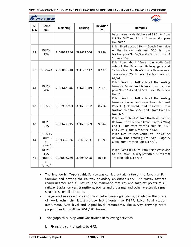
39 DGPS-
19A 2108962.366 299612.066 5.890
Pillar Fixed about 110mts South East side
of the Railway gate and 10.5mts from
traction pole No. 59/2 and 9.5mts from K M
Stone No.59.
40 DGPS-20 2106846.418 301193.117 8.437
Pillar Fixed about 47mts from North East
side of the Kalamboli Railway gate and
125mts from South West Side Valadeshwar
Temple and 25mts From traction pole No.
61/24.
41 DGPS-
20A 2106642.346 301410.019 7.501
Pillar Fixed on Left side of the leading
towards Panvel and 6.5mts from traction
pole No.61/34 and 51.5mts From Km Stone
No.62.
42 DGPS-21 2103908.993 301606.992 8.776
Pillar Fixed on Left side of the leading
towards Panvel and near truck terminal
Panvel (Kalamboli) and 19.2mts from
traction pole No. 64/23 and 33mts from F.S
No.64/7.
43 DGPS-
21A 2103629.715 301600.639 9.044
Pillar Fixed about 200mts North side of the
Railway Line Fly Over (Pane Express Way)
and 11.3mts from traction pole No. 65/1
and 7.2mts From K M Stone No.65.
44
DGPS-15
(Route-1
at
Panvel)
2101365.126 301736.83 11.095
Pillar Fixed On 15m North East Side Of The
Railway Line Crossing Fly Over Bridge &
8.5m From Traction Pole No-48/2.
45
DGPS-
15A
(Route-1
at
Panvel)
2101092.269 302047.478 10.746
Pillar Fixed On 13.5m From North West Side
Of The Panvel Railway Station & 8.1m From
Traction Pole No 67/48.
• The Engineering Topographic Survey was carried out along the entire Suburban Rail
Corridor and beyond the Railway boundary on either side. The survey covered
road/rail track and all natural and manmade features and take-off points of all
railway tracks, curves, transitions, points and crossings and other electrical, signal
structures, installations etc.
• The ground survey work was done in detail covering all items, detailed in the Scope
of work using the latest survey instruments like DGPS, Leica Total station
instrument, Auto level and Digital level instruments. The survey drawings were
prepared in Auto CAD in DWG/DXF format.
• Topographical survey work was divided in following activities:
i. Fixing the control points by GPS.

TECHNO-ECONOMIC SURVEY AND PREPARATION OF DPR FOR PANVEL-DIVA-VASAI-VIRAR CORRIDOR
Draft Feasibility Report APRIL, 2013 4-6
ii. Traversing and calculation of closing error.
iii. Leveling including fixing of bench marks.
iv. Detailing of ground features and plotting the same in AUTO Cad.
v. Site verification by the agency.
vi. Complete verification of all above data/drawings by RITES Engineers.
4.1.3 Methodology of Error Distribution
In Traversing:
Linear correction of any side = Closing error X length of that side/perimeter of traverse
Check for Angular Work:
The sum of interior angles= (2n-4) 90°
The sum of exterior angles= (2n+4) 90°
Where n=no. of sides of the traverse
In Levelling:
Proportionate distribution of error to the stations.
Arithmetical check:
∑ BS - ∑ FS = ∑ RISE - ∑Fall = Last R.L – First R.L. The Permissible error in leveling is
6mm / Km.
4.1.4 Survey Accuracy
• Linear measurement accuracy was 4 cm per Km.
• The Northing and Easting obtained by GPS coordinates used for survey detailing.
The closed traverse was run in between these GPS stations by using Total Stations
to establish secondary traverse station, and the same were downloaded into the
computer to convert the same data in Autocad-2010 format. Detailed topographical
survey was carried out with the help of these traverse stations and final preparation
of the survey map of the area. Survey plotting was carried out in the office
simultaneously with the field work.
• The plotted sheets were taken to the site for verification to ensure that no details or
structure was left out. Necessary modifications to the drawings were made and
then final prints were taken from the plotter at 1:1000 scale. The entire proposal,
the mode of alignment and location of proposed stations is being designed with
help of MX Rail Software. Temporary bench marks were established as directed by
the engineer-in-charge.
4.1.5 Topographical Survey Procedure
4.1.5.1 Reconnaissance
Before starting the topographic survey, tentative route alignment was marked
on eicher/goggle map. The survey teams along with RITES’s engineers have done
reconnaissance survey to familiarize the route alignment and identification of

TECHNO-ECONOMIC SURVEY AND PREPARATION OF DPR FOR PANVEL-DIVA-VASAI-VIRAR CORRIDOR
Draft Feasibility Report APRIL, 2013 4-7
the location for fixing the control traverse points and TBMs location. The
constraints likely to be encountered during survey work were also identified.
4.1.5.2 Traversing
45 Nos of DGPS points were established with the help of GPS between Vasai and
Panvel. The traverse points between these GPS traversing stations were
established by running closed traverse with the help of Total station.
4.1.5.3 Precise Levelling
Levels of control traversing stations were established by using auto level. TBMs
for the entire route alignment were established every 0.50 km (average) by
Double territory method and fixed on available permanent structures along the
route alignment. The Levelling was carried out by using precision auto level with
accuracy of ±6JK. Reduced levels of all traverse staKons and permanent control
points were also taken w.r.t. TBMs.
4.1.5.4 Detailed Survey
• Based on the ‘Easting’ & ‘Northing’ values arrived by the Traversing and
Elevation by Precise Levelling, detailed survey was carried out along the
alignment.
• The survey covered road/rail track showing important structures all the bye
lanes, footpaths, dividers/central verges, roads, railway tracks, trees,
manholes and other structures, Nallahs, Storm water drains, H.T., L.T.,
Transmission lines, bridges, ROBs/RUBs/FOBs with type and spans, ponds,
HFL and bed level of streams/Nallahs, level crossing with their type, traction
masts, signal posts, etc. Spot/ Ground levels were taken at 25 m intervals in
longitudinal as well as traverse direction and at sudden change of levels and
other features etc., as decided by the Engineer-in-charge.
• Details of built-up areas including setbacks from building line / boundary
wall, utility services such as electric lines, telephone lines, HT lines and over
head crossings, manholes details, vertical clearance of overhead utilities etc.
were taken and marked on the drawings.
• Location of approach roads, main roads, lanes showing road/lane name,
carriageway, footpaths, central verge, drains and the widths of all the main
and approach roads and at locations where there is a sudden change in
widths of roads were measured physically and marked on the drawings.
• Details of Railway tracks along the proposed alignment including take off
points, FOBs, transitions, crossings, switches and other details including
electrical structures with their distances were taken. FOB and Power line
Crossings list has been submitted along with GSAR.
• Details of Religious structures such as temples, Gurudwaras, Mosques,
Churches, and Monuments, tombs etc., clearly marking the Railway

TECHNO-ECONOMIC SURVEY AND PREPARATION OF DPR FOR PANVEL-DIVA-VASAI-VIRAR CORRIDOR
Draft Feasibility Report APRIL, 2013 4-8
boundary all along the corridor and giving cross reference of these
structures with reference to the Railway boundary were taken.
4.2 PLANNING AND DESIGN NORMS
The proposed corridor will consist of two broad gauge (BG) lines at 5.3 m centre to
centre for at grade construction. Track centres of 4.725m have been adopted for
Elevated portion of alignment. The alignment is in conformity with letter No.
2010/Proj./Genl./3/3 dated 23.12.2011, for Standards of Track Structure for Metro
Railway/MRTS system for Broad gauge including details of curvature, gradients,
turnouts, switch expansion joints etc.
4.2.1 FORMATION FOR AT- GRADE ALIGNMENT
Formation width of 12.150 m (minimum) for embankment and 11.550 m
minimum width in cutting (excluding side drains) has been proposed. Width in
embankment and cutting shall be increased on curves based on extra ballast and
extra clearance required on curves. Moorum blanketing, 300 mm thick, has been
proposed as soil is alluvial containing substantial plastic fines. Earth work shall be
done with contractor’s own good quality earth and fully compacted to 98%
maximum dry density using mechanical means.
4.2.2 SYSTEM PARAMETERS
The broad parameters of study has been decided after detailed evaluation of all
available options geographically in context of transport needs of area and
projected.
• Category of line : Group ‘C’
• Track Gauge : Broad Gauge (1676 mm)
• Track Centre : 5300 mm (BG)
• Traction : 25 kV ac OHE
• Rolling Stock : Normal EMU Stock, 3660 mm wide
• Speed potential of the section : 100 kmph
• Maximum degree of curvature : 1.00° fully transitioned, preferably relaxable
up to 3° at difficult locations
• Obligatory Points : i. Proposed two lines shall pass through all
existing stations.
ii. Propose traffic facilities, junction
Arrangements and yard plans.
• Width of Formation : i. Minimum width in embankment 12.150 m

TECHNO-ECONOMIC SURVEY AND PREPARATION OF DPR FOR PANVEL-DIVA-VASAI-VIRAR CORRIDOR
Draft Feasibility Report APRIL, 2013 4-9
ii. Minimum width in cutting (excluding
side drains) 11.550 m
Width in embankment and cutting shall be increased on curves based on
extra ballast and extra clearance required on curves.
• Side slopes : H : V
i. Hard Rock : ¼ : 1
ii. Soft Rock : ½ : 1
iii. Moorum : 1 : 1
iv. Ordinary soil : 2 : 1
• Ruling Gradient : Existing ruling gradient of the section shall be
proposed.
• Gradient in yards : Preferably level, however if yards are located on
Gradients, then gradient shall generally be
not steeper than 1 in 1200 or consistent
with the prevailing gradient in existing yard.
• Track centre : 5.30 m
• Level Crossings : Level crossings to be avoided. DFCCIL in
Panvel Juichandra section have proposed
ROBs /RUBs on the existing level crossings
on their alignment .
• Track structure
S.N. Parameters Standards proposed
I. Rails 60 Kg. FF Ist class
II. Sleepers MBC sleepers with density of 1660 Nos. per
Km
III. Ballast Cushion 350 mm of 65 mm size.
IV. Welding of rails CWR/LWR to be provided as far as possible
V. Points & Crossings 60 Kg on MBC sleepers 1 in 12 curved
switch negotiated by passenger train
VI. Loading standard of Bridges 25 T -2008 loading
VII. Permissible maximum length of
ruling gradient in one stretch
No restriction
VIII. Maximum grade on approach to
main river bridges
As flat as possible consistent with site
conditions and not steeper than 1 in 200
compensated

TECHNO-ECONOMIC SURVEY AND PREPARATION OF DPR FOR PANVEL-DIVA-VASAI-VIRAR CORRIDOR
Draft Feasibility Report APRIL, 2013 4-10
IX. No. of stationed to be opened All existing stations
X. Length of Train 12 Car EMU rake
XI. Maintenance New Depot at Kalwar for inspection,
maintenance
XII. Signaling & Train Control Automatic Multi Aspect Colour Light
Signalling (MACLS) with RRI for Yards
4.2.3 TECHNICAL STANDARD FOR TRACK STRUCTURE
Track Structure shall be designed to cater for
• Gauge. Broad gauge- 1676/1673 mm (nominal)
• Speed potential- 160 kmph (max.)
• Static axle load- 20 T (max.)
• Design rail temperature. range – (-) 10 degree Celsius to 70 degree Celsius
The track structure will fulfil following requirements.
• The track structure will conform to/ satisfy Schedule of Dimension
requirement and other maintenance instructions of safe operating Systems.
• Ride comfort and running safety of track vehicle dynamics will be satisfied.
• The track stature will be designed with Long welded/ Continuous welded
rail.
• The horizontal alignment shall consist of a series of straights joined to
circular curves generally with transition curves.
• The vertical alignment shall be designed to achieve a smooth profile line
with gradual changes. Changes in the profile shall be connected by vertical
curves, which shall be as generous in length as the location allows. Vertical
curves shall not be located at stations within the length of platform.
Rail
• The rail shall be 60 E1 (UIC 60), 1080 grade Head Hardened on curves and
approached of stations for main line track. The rail on depot lines shall be 60
E1 (UIC 60), 880 grade.
• The rail shall be class ‘A’ rails as per IRS-I-12-2009 specification and it shall
be manufactured and tested in accordance with IRS-T-12-2009 (with latest
amendment).
• Welding of rail shall conform to Indian Railway Specifications and technical
instructions issued from time to time.

TECHNO-ECONOMIC SURVEY AND PREPARATION OF DPR FOR PANVEL-DIVA-VASAI-VIRAR CORRIDOR
Draft Feasibility Report APRIL, 2013 4-11
Sleeper and fastening
• The PSC sleepers shall be in accordance with RDSO drawing no. T-2496 and
specification IRS-T-39 (revised from time to time) and compatible fastening
system with minimum toe load of 1045 kg and approved by Indian Railway.
Turnouts
General
• On main lines, the turnouts and diamond crossing shall be of the
following types:
� 1 in 12 Type turnout
� 1 in 8.5 type turnout
� Scissors crossover of 1 in 12 type consisting of 4 turnouts and
1 diamond crossing
• On depot lines the turnouts and diamond crossing shall be of the
following type
� 1 in 8.5 type turnout
� Scissors crossover of 1 in 8.5 type consisting of 4 turnouts and
1 diamond crossing
� 1 in 8.5 derailing switches/ 1 in 8.5 type symmetrical split
turnout.
Type and geometry of turnout
Detailed design of all turnouts, scissors crossover shall comply with the
following geometrical parameters.
a. 1 in 12 turnout
The design shall be tangential with switch entry angle not exceeding of
20’00”. The radius of lead rail of turnout shall not be less than 410m. All
clearance shall be in accordance with relevant provisions of SOD.
b. 1 in 8.5 turnout
The design shall be tangential with switch entry angle not exceeding of 0°
20’00”. The radius of lead rail of turnout shall not be less than 218m. All
clearance shall be in accordance with relevant provisions of SOD.
c. Scissors Crossover
The base geometry of the turnouts of Scissors crossover shall be same as
that of corresponding ordinary turnouts.

TECHNO-ECONOMIC SURVEY AND PREPARATION OF DPR FOR PANVEL-DIVA-VASAI-VIRAR CORRIDOR
Draft Feasibility Report APRIL, 2013 4-12
Operating requirement of turnout, Scissor crossover
Track layout design shall permit trains to operate at maximum capability
wherever possible. Turnouts and crossover shall be selected such that they do
not form a restriction to the operating speed on the diverging route. Switches
and crossings shall not be located on transition curves or vertical curves.
Speed
The turnout shall be designed for 110 Kmph on Mainline side with speed
restrictions on curves if required.
The minimum speed potential of the various turnouts and scissors crossover
on the Turnout side should be as follows:
Broad Gauge
• 1 in 12 type turnout (Speed potential of 50 Kmph)
• 1 in 8.5 type turnout (Speed potential of 30 Kmph)
• Scissors crossover 1 in 12 type (Speed potential of 50 Kmph)
• Scissors crossover 1 in 8.5 type (Speed potential of 30 Kmph)
• 1 in 8.5 type symmetrical split turnout (Speed potential of 40 Kmph)
Sleepers
a. Sleeper shall be of pre-stressed concrete, mono-block, suitable for
installation in track both with and without signalling circuits and with and
without electrification.
b. Sleepers shall be designed to provide a minimum service life of fifty years
under nominal axial load of 20 tonnes and maximum speed of 110 Kmph.
Rail seat pads and liners shall be designed to provide a minimum services
life of 10 years.
c. The sleeper base surface shall be rough cast while the top and side surface
shall be smooth to prevent retention of moisture and foreign materials.
d. Sleepers must be suitable for installation by track laying machines and
sleepers insertion equipment of a type used for isolated sleeper insertion.
e. The sleeper must be able to transfer all the relevant track forces generated
by train operations and the forces of rail expansion and contraction to the
ballast.
4.2.3.1 Track slab for ballast less track
Track shall be laid on cast in situ/precast reinforced plinth or slab, herein
referred to as the ‘Track Slab’. The track slab shall be designed as plinth beam or
slab type ballast less track structure with derailment guards. It shall
accommodate the base plates of the fastening system. In general, track slab

TECHNO-ECONOMIC SURVEY AND PREPARATION OF DPR FOR PANVEL-DIVA-VASAI-VIRAR CORRIDOR
Draft Feasibility Report APRIL, 2013 4-13
(including sleeper, if any) on which the fastening and rail are to be fitted shall
perform the following functions.
i) Resist the track forces (static and dynamic)
ii) Provide a level base for uniform transmission of track/ rail forces
iii) Have geometrical accuracy and enable installation of track to the
tolerances laid down.
iv) Ensure drainage.
v) Resist weathering.
vi) Be construction friendly, maintainable and quickly repairable in the event
of a derailment. The ‘Repair and Maintenance methods’ shall be detailed
in a Manual to be prepared and made available.
vii) Ensure provision for electrical continuity between consecutive plinths /
slabs by an appropriate design.
viii) Plinth beam or slab of ballastless track should be suitable for embankment
or viaduct or tunnel/ Underground structure.
ix) Proper design of expansion joints suitable for joints of viaduct structure.
x) Design should be suitable for curves as per SOD of Metro system.
xi) Design of sub-grade/embankment for slab should be furnished to ensure
durability and functional stability in service.
xii) Design should be suitable and incorporate provision of utilities e.g. cable,
wires, ducts, water channels, etc.
4.2.3.2 Derailment Guards
The derailment guard should be provided inside/outside of running rail on
viaduct, at grade section locations specified by the Metro railway. The lateral
clearance between the running rail and the derailment guard shall be 250 ±40
mm. It shall not be lower than 25mm below the top of the running rail and
should be clear of the rail fastenings to permit installation, replacement and
maintenance. Derailment guard shall be designed such that in case of
derailment:
i) The wheels of a derailed vehicle under crush load, moving at maximum
speed are retained on the viaduct or tunnel:
ii) Damage to track and supporting structure is minimum.
4.2.3.3 Fastening system for ballastless track
The performance criterions for fastening system of ballastless track is already
specified separately vide Railway board letter No 2009/Proj /MAS/9/2 dated
21.05.2010.

TECHNO-ECONOMIC SURVEY AND PREPARATION OF DPR FOR PANVEL-DIVA-VASAI-VIRAR CORRIDOR
Draft Feasibility Report APRIL, 2013 4-14
4.2.3.4 Glued Insulated Rail joint
Normally glued joint should be avoided .Wherever inescapable, G3 (L) type of
glued insulated rail joint shall be used as per RDSO drawings no. T- 5843. The
glued joints shall be manufactured and tested in accordance with RDSO’s
Manual for Glued insulated Rail Joints- 1998’ with all amendments.
4.2.4 Technical Specification for turnouts
4.2.4.1 General
i) All the points shall be capable of being operated by electric motors in
accordance with the signaling specification.
ii) The top surfaces of PSC sleeper/ RCC slab supporting rail seat of turnouts and
scissors crossover shall be flat without any cant/ slope.
iii) The track form of the turnout shall have uniform resilience as that of the
adjoining track form.
iv) The fixation of turnouts/ scissors cross over on track slab shall be through base
plates/bearing plates.
4.2.4.2 Rails
i) The rails used in turnouts shall be 1080 grade Head Hardened.
ii) The rails used for manufacturing of turnouts shall satisfy the following
conditions:
a) The rails shall be manufactured and tested in accordance with IRS/T-12-2009
with latest amendments.
b) The section of rails shall be 60 E1 (UIC 60) for stock, lead and 60 E1A1 (ZUI-
60) for switch rail.
c) The rails shall qualify as Class ‘A’ rails as per IRS/T-12-2009.
d) The rails shall be with ends un-drilled.
e) The rails shall be of grade 1080 HH and be suitable for being welded by
alumino-thermic or flash butt welding technique.
4.2.4.3 Switches
a) Each switch device shall consist of two stock rails one left hand and one right
hand and two switch rails, one left hand and one right hand. Switches shall be
manufactured to suit to special asymmetrical section switch rail type 60 E1A1
(ZUI-60)
b) The switch rail shall be one piece with no weld or joint within the switch rail
length.

TECHNO-ECONOMIC SURVEY AND PREPARATION OF DPR FOR PANVEL-DIVA-VASAI-VIRAR CORRIDOR
Draft Feasibility Report APRIL, 2013 4-15
c) The end of the asymmetrical switch rail shall be forged to 60 E1 (UIC 60) rail
profile with minimum length of 60kg profile for 500 mm. The forged 60E1A1
(ZUI- 60) switch rail end shall be suitable for welding or installation of insulated
rail joint.
d) Slide chairs in the switch portion shall be coated with an appropriate special
coating so as to reduce the point operating force and to eliminate the
requirement of lubrication of sliding surface during service.
e) Switches shall provide suitable flange way clearance between the stock rail and
the switch rail with the switch rail in open position (minimum 60mm). The 1 in
12 and 1 in 9 turnout shall be provided with second drive or other suitable
arrangement to ensure minimum gap of 60mm at JOH as well as proper housing
of switch rail with stock rail upto JOH. 1 in 8.5 and 1 in 7 turnouts may not be
provided with second drive arrangement, however minimum gap of 60 mm at
JOH as well as proper housing of switch rail with stock rail upto JOH should be
ensured. The nominal opening of switch at toe of switch shall be kept as
160mm.
f) The switch manufacturer shall include provision for all holes required to main
drive machines, stretcher bars and detection equipment to suit the
requirements of the signaling and switch operating system duly champhered to
avoid stress connections at the edge of the holes.
g) The switches shall be designed with an anti–creep device at the heel of switch to
withstand thermal forces of the CWR track.
h) The switches and all slide chairs shall be same for ballasted and ballastess
turnouts.
4.2.4.4 Crossings
i) All crossings shall be cast manganese steel (CMS) crossings with weldable rails
of minimum 1.2 m length undrilled for welding into the overall turnout.
ii) The CMS crossings shall be manufactured from Austenitic Manganese steel as
per UIC 866.
iii) All CMS crossings shall have welded leg extension of 60 E1 (UIC 60) rails. This
shall be achieved by flash butt welding of buffer transition rail piece of suitable
thickness to CMS crossings and rail leg extension.
iv) All CMS crossings shall have a minimum initial hardness of 340 BHN.

TECHNO-ECONOMIC SURVEY AND PREPARATION OF DPR FOR PANVEL-DIVA-VASAI-VIRAR CORRIDOR
Draft Feasibility Report APRIL, 2013 4-16
v) All CMS crossings and their welded leg extensions for all scissors crossovers shall
be suitably dimensioned so as to eliminate the necessity of providing small cut
rail piece for the purpose of inter-connection. However, the need for providing
insulated glued joints from signaling requirement point of view shall be taken
care of in the design, if required.
vi) The provision of rail cant shall be taken care of on the top surface of the CMS
crossing and the bottom surface of all CMS crossing shall be flat.
4.2.4.5 Check Rails
i) The check rail section shall be 33 C1 (UIC33) or similar without any direct
connection with running rails.
ii) Check rails shall have the facility for the adjustment of check rail clearances upto
10 mm over and above the initial designed clearance.
iii) Each check rails end shall be flared by machining to have minimum clearance
of 62 mm at end.
iv) The check rail connections in turnouts shall be through specially designed
bearing plates/ brackets
v) All the check rails shall be higher by 25mm above running rails. The lengths and
positions of the check rail in diamond crossings shall provide safety and be
compatible with the overall track layout.
4.2.5 Switch Expansion Joint
i) The SEJ for ballasted track shall be laid on PSC sleepers whereas the SEJs for
ballastless track, if required shall be laid on reinforced concrete slab.
ii) The rail section for all SEJs shall be UIC 60, 1080 HH grade as per IRS- T-12-2009.
iii) The SEJ for ballasted track shall be designed for a maximum gap of 80 mm.
iv) The SEJ for ballastless track should be designed for the maximum gap required as
per design.
v) The ballasted SEJ shall be as per RDSO drawing T- 6902 & T- 6922.
vi) The ballasted SEJ for BG shall be laid with PSC sleepers as per RDSO drawing T-
4149. For standard Gauge, PSC sleeper shall be designed such that SEJ to RDSO
drawing along with its bearing plates/Chairs may be accommodated for
installation of SEJ.
vii) Sleepers used for SEJs shall be flat and cant will be provided through CI chair.
viii) The SEJ shall be suitable for two way directional traffic.

TECHNO-ECONOMIC SURVEY AND PREPARATION OF DPR FOR PANVEL-DIVA-VASAI-VIRAR CORRIDOR
Draft Feasibility Report APRIL, 2013 4-17
4.2.6 Geometric Design Parameters
4.2.6.1 Horizontal Curves
• The minimum adopted curve radius for main running lines is 300 m for at-
grade/elevated.
• Radius of curves at stations shall not be less than 1000 m in elevated and at-
grade sections.
• Cant deficiency (Cd) allowed may not exceed 100 mm and the Actual Cant (Ca)
may not normally exceed 125 mm.
4.2.6.2 Safe speed on curves
The safe speed on curves is determined by the formula:
V safe = 0.27 ���� R (Ca + Cd)
where,
V safe = Safe speed in kmph
R = Radius in m
Ca = Applied Cant in mm
Cd = Cant deficiency in mm
4.2.6.3 Vertical curves
Minimum radius of vertical curves at change of grade points (wherever change
of grade is steeper than 0.4%) to be adopted, is 2500-m in normal circumstances
and 1500 m in exceptional situations. There should be no overlap between
vertical curves and transition curves. The minimum length of vertical curves is to
be 20 m.
4.2.6.4 Gradients
On main line tracks, following criteria/guidelines has been adopted.
• At station level.
• In mid-section, the gradients, not steeper than 0.5%. However, after
Juchandra, gradient of 2.0% has been provided.

TECHNO-ECONOMIC SURVEY AND PREPARATION OF DPR FOR PANVEL-DIVA-VASAI-VIRAR CORRIDOR
Draft Feasibility Report APRIL, 2013 4-18
4.3 DESCRIPTION OF ALIGNMENT
4.3.1 Introduction
• Proposed new Suburban corridor from Panvel to Virar is to run along the existing
Panvel – Diva – Vasai line of Central Railway and then Vasai Road to Virar of
Western Railway, to be accommodated generally, within the existing right of way,
elevated/at-grade, in order to avoid/minimize acquisition of private land/property.
The corridor proposed is to have double line track, with a capacity to run 12 coach
trains.
• From Panvel to North of Nilaje, the alignment is proposed at-grade. Between Nilaje
and Kopar, the alignment is proposed elevated. Between Kopar and north of
Juchandra, the alignment is again proposed as at-grade. Between south of Vasai
Road and Virar, the alignment is again proposed as Elevated.
• There is planned Dedicated Freight Corridor (DFC) running almost parallel to existing
corridor between Panvel to Juchandra section. The DFC is planned on east of
existing double line track. Existing corridor has 14 stations between Panvel and Virar
covering an approximate distance of 70 km (Table 4.2).
Table 4.2: Stations on Panvel – Virar Section
S. No. Stations Railways Kms from CSTM
(via Diva)
Panvel – Dativali Section
1 Panvel 68.128
2 Kalamboli 62.892
3 Navade Road 60.334
4 Taloje Panchanand 57.092
5 Nilaje 48.63
6 Dativali 44.172
Dativali -Virar Section
7 Kopar 48.79
8 Bhiwandi Road 56.60
9 Kharbhao 64.94
10 Kaman Road 73.051
11 Juchandra 79.85
12 Vasai Road 84.11
13 Nalasopara 88.27
14 Virar 92.32 Source: System map of Mumbai Division (Central Railway)
• Interconnecting track loops to provide direct connectivity to/from Central Railway
main line stations of Dombivli as well as Diva are available between Kopar-Dativali
sections. These loops are located on east side of Central railway main line corridor
of Dombivli -Diva.

TECHNO-ECONOMIC SURVEY AND PREPARATION OF DPR FOR PANVEL-DIVA-VASAI-VIRAR CORRIDOR
Draft Feasibility Report APRIL, 2013 4-19
• Between Nilaje - Kopar section, which is 7.90 Km, the alignment is proposed
elevated for about 6.40 Km.The alignment crosses the Dombivli – Diva Central
Railway main line corridor, connecting loops and Panvel - Diva Central Railway main
line corridor as elevated. For crossing Panvel - Diva corridor, a ramp with a grade of
1:200 (0.50%) has been proposed to become elevated. In remaining section i.e. 1.50
Km, the alignment is proposed at grade, where generally adequate space is available
to accommodate new sub-urban corridor.
• The alignment of proposed corridor in Vasai Road - Virarsection is proposed
elevated due to land constraints. Also future proposal of 5th/6th line between
Borivali to Virar is kept in mind while proposing the alignment of Panvel -
Virarcorridor. There are 2 ROBs in this section. Thus, the vertical profile of the
proposed corridor is decided by giving due considerations to these fixed structures.
In general, the ground clearance of ROBs above the existing Rail level is 7.5 m to 8.0
m and required clearance for the proposed corridor above ROBs is 5.50 m.
Therefore, the proposed alignment of the new sub-urban corridor is planned at a
height of 16.50 m to 17.0 m including depth of deck.
• With a view of minimizing land/property acquisition requirement, it is
recommended to adopt general arrangement of two proposed corridors (i.e. Panvel
- Virarand Borivali-Virar 5th/6th line) between Vasai Road- Virar sections just over
one another. This scheme could be feasible if elevated construction is done first
with provision of At Grade track on either side of proposed pier.
• The details of existing ROBs between various sections are given in Table 4.3.
Table 4.3: List of Existing ROBs on Panvel – Virar section
S.
No. Section Name of ROB Rly Km
Vertical
Clearance
Floor
Height
from RL
Alignment
Proposal
1 Panvel -
Nilaje
Off Sion - Panvel
Expressway near
Sector-19, Panvel
67.25 5.60 9.00 At Grade
ROB (U/C) near
Khanda colony 66.38 8.10 11.50 At Grade
Mumbai - Pune
Expressway near
Asudgaon
65.23 5.60 7.90 At Grade
MIDC road near
east of Navade
Phatak
60.28 5.20 8.75 At grade
2 Nilaje -
Kopar
Crossing Kalyan-
Shilphata
Road(ROB-2)
47.318 8.90 10.80 At grade
Crosiing Kalyan-
Shilphata Road
(ROB-1)
47.298 6.10 7.70 At grade

TECHNO-ECONOMIC SURVEY AND PREPARATION OF DPR FOR PANVEL-DIVA-VASAI-VIRAR CORRIDOR
Draft Feasibility Report APRIL, 2013 4-20
S.
No. Section Name of ROB Rly Km
Vertical
Clearance
Floor
Height
from RL
Alignment
Proposal
Crossing Thane-
Kalyan main line,
down ramp to Diva
and Panvel
48/21-
24 6.50 7.50 Elevated
3 Kopar -
Vasai Road
At NH 3 54.188 6.40 8.20 At Grade
At Mumbai Nasik
Highway near
MIDC pipeline
54.276 6.20 8.20 -DO-
4 Vasai Road
- Virar
Between Vasai
road and
Nalasopara
Km
52/8-9 6.00 7.45 Elevated
Between
Nalasopara and
Virar
Km
55/13-
14
6.50 8.145 -DO-
• The details of existing FOBs between various sections are given in Table 4.4.
Table 4.4: List of existing FOBs on Panvel - Virar Section
S.NO STATION
NAME Rly
Chainage Rail
level(m)
Bottom
Floor level
of FOB(m)
Clearance ht
(in m) EXISTING/
NEW REMARKS
1 Panvel
68.2 11.34 18.95 7.61 Existing No
Change
11.305 18.4 7.095 Existing No
Change
2 Kalamboli 62.95 4.927 11.808 6.881 Existing To be
extended
3 Navde Road 60.64 8.332 15.306 6.97 Existing To be
extended
4 Taloje 57.22 8.551 15.49 6.939 Existing To be
extended
5 Nilaje 48.453 10.48 17.5 7.02 Existing To be
extended
6 Dativali 44.14 8.22 15.34 7.12 Existing To be
extended
7 Kopar 47.675 13.96 22.283 8.323 Existing To be
extended
8 Bhiwandi
Road 55.555 23.166 30.19 7.024 Existing
To be
extended
9 Kharbao 64.88 6.891 13.857 6.966 Existing To be
extended
10 Kaman Road 73.291 21.882 28.795 6.904 Existing To be
extended
11 Juchandra 78.63 8.262 15 6.738 Existing To be
extended
12 Vasai Road 83.955 5.8 12.9 7.1 Existing

TECHNO-ECONOMIC SURVEY AND PREPARATION OF DPR FOR PANVEL-DIVA-VASAI-VIRAR CORRIDOR
Draft Feasibility Report APRIL, 2013 4-21
S.NO STATION
NAME Rly
Chainage Rail
level(m)
Bottom
Floor level
of FOB(m)
Clearance ht
(in m) EXISTING/
NEW REMARKS
5.62 13.12 7.5 Existing
84.057 5.59 12.95 7.36 Existing To be
extended
84.212 5.75 13.12 7.37 Existing To be
extended
13 NalaSopara
88.242 6.0 12.50 6.50 Existing To be
extended
88.366 6.50 13.0 6.50 Existing To be
extended
• There are 25 no. existing major bridges along the Panvel - Virar line. The details are
given below (Table 4.5).
Table 4.5: List of Major Bridges
S.No. SECTION BR.NO LOCATION SPAN CLASS Type of
Bridge REMARKS
1 Navde Road-
Kalamboli 61/1 61/5A-61/14 4x12.20 MAJ PSC GIRDER
Above
Kasadi
River
2 Taloje-Navde
Road 58/1 58/20-58/24 7x12.2 MAJ PSC GIRDER
Baba
Matang
river
3 Nilaje-Taloje 51/3 51/20-51/22 3x4.57 MAJ RCC SLAB Above
Nalah
4 Nijaje-Taloje 49/2 49/40-49/44 5x12.2 MAJ PSC GIRDER Above
Mutali
River
5 Dativali-Nilaje 46/2 46/10-46/12 5x3.05 MAJ RCC SLAB Above
Nalah
6 Kopar-Dativali 74/2 47/32-47/34 2x20.10 MAJ STEEL
GIRDER
7 Kopar-Diva 45/2 45/7-45/9 3x10.40 MAJ
8 Bhiwandi
Road-Kopar 51/2 51/28-52/2 6x76.2 MAJ
STEEL
GIRDER
Above
Ulhas
River
9 Bhiwandi
Road-Kopar 54/1 54/3-54/5 1x12.260 MAJ
STEEL
GIRDER
10 Bhiwandi
Road-Kopar 55/2 55/30-55/34 2x45.7 MAJ RCC SLAB BMC PIPE
11 Kharbao-
Bhiwandi
Road
57/2 57/20-57/22 1x18.30 MAJ STEEL
GIRDER RUB(NH-
3)
12
Kharbao-
Bhiwandi
Road 61/3 61/23-61/25 1x18.30 MAJ
STEEL
GIRDER Above
Nallah
13 Kharbao-
Bhiwandi 62/3 62/21-62/23 3x45.76 MAJ
STEEL
GIRDER
Above
Kamwadi

TECHNO-ECONOMIC SURVEY AND PREPARATION OF DPR FOR PANVEL-DIVA-VASAI-VIRAR CORRIDOR
Draft Feasibility Report APRIL, 2013 4-22
S.No. SECTION BR.NO LOCATION SPAN CLASS Type of
Bridge REMARKS
Road River
14 Kharbao-
Bhiwandi
Road 63/2 63/31-63/33 1x18.30 MAJ
STEEL
GIRDER
15 Kaman Road-
Kharbao 65/3 65/35-65/37 1x18.30 MAJ
STEEL
GIRDER
16 Kaman Road-
Kharbao 66/1 66/15-66/17 1x12.20 MAJ
STEEL
GIRDER
17 Kaman Rd-
Kharbao 67/1 67/11-67/15 1x30.50 MAJ
STEEL
GIRDER
Above
Nallah
18 Kaman Road-
Kharbao 69/1 69/4-69/6 2x18.30 MAJ RCC BOX
Above
monghir
Nallah
19 Kaman Road-
Kharbao 70/2 70/12-70/14 1x18.2 MAJ RCC SLAB
Above
Nallah
20 Kaman Road-
Kharbao 72/1 72/2-72/4 1x12.2 MAJ
STEEL
GIRDER Above
Nallah
21 Juichandra-
Kaman Road 74/1 74/9-74/17 3x30.5 MAJ
STEEL
GIRDER
Above
Kaman
River
22 Juchandra-
Kaman Road 76/2 79/6-79/9 1x18.30 MAJ
STEEL
GIRDER RUB(NH-
8)
23 Juichandra-
Kaman Road 76/4 76/23-76/27 1x32.47 MAJ
STEEL
GIRDER
Above
Nallah
24 Vasai Road-
Juichandra 79/2 79/18-79/20 2x12.2 MAJ
STEEL
GIRDER Above
Nallah
25 Vasai Road-
Juchandra 79/3 79/31-79/33 1x12.2 MAJ
STEEL
GIRDER Above
Nallah
26 Vasai Road-
Juchandra 80/2 80/27-80/29A 1x30.5+2x18.3 MAJ
STEEL
GIRDER
Above
Sopar
Nallha
• There are 123 no. existing minor bridges along the Panvel - Virar line. The details are
given below (Table 4.6).
Table 4.6: List of Minor Bridges
S. NO SECTION BR. NO LOCATION SPAN CLASS TYPE OF
BRIDGE
1 Kalamboli -
Panvel
48/2 and
67/2
67/26-
67/28A 1x3.05 MIN RCC SLAB
2 Kalamboli-
Panvel 67/1 67/13-67/16 1x1.22 MIN HP CULVERT
3 Kalamboli -
Panvel 66/1 66/22-66/24 1x3.66 MIN RCC BOX
4 Kalamboli -
Panvel 65/2
65/30-
65/14A 1x3.66 MIN RCC SLAB
5 Kalamboli -
Panvel 65/1 65/6-65/8 1x1.22 MIN RCC BOX

TECHNO-ECONOMIC SURVEY AND PREPARATION OF DPR FOR PANVEL-DIVA-VASAI-VIRAR CORRIDOR
Draft Feasibility Report APRIL, 2013 4-23
S. NO SECTION BR. NO LOCATION SPAN CLASS TYPE OF
BRIDGE
6 Kalamboli -
Panvel 64/2 64/26-64/28 1x1.22 MIN RCC BOX
7 Kalamboli -
Panvel 64/1 64/12-64/13 3x2.44 MIN RCC BOX
8 Kalamboli -
Panvel 63/3 63/34-63/36 1x0.915 MIN HP CULVERT
9 Navade Road-
Panvel 63/2 63/26-63/28 1x1.22 MIN RCC SLAB
10 Navade Road-
Panvel 63/1 63/6-63/8 3x2.44 MIN RCC SLAB
11 Navade Road-
Kalamboli 62/1 62/24-62/26 3x2.44 MIN RCC SLAB
12 Navade Road-
Panvel 61/2 1x0.915 1x0.915 MIN RCC SLAB
13 Taloje-Navde
Road 60/1 60/4-60/2 1x1.83 MIN RCC SLAB
14 Taloje-Navde
Rd 59/2 59/26-59/28 1x1.83 MIN RCC SLAB
15 Taloje-
Navade Road 59/1 59/2-59/4 3x3.05 MIN RCC SLAB
16 Nilaje-Taloje 56/2 56/20-56/22 1x1.22 MIN RCC SLAB
17 Nilaje-Taloje 56/1 56/10-56/12 1x2.44 MIN RCC SLAB
18 Nilaje-Taloje 55/2 55/20-55/22 1x3.66 MIN RCC SLAB
19 Nilaje-Taloje 55/1 55/9-55/12 1x1.22 MIN RCC SLAB
20 Nilaje-Taloje 54/2 54/15-54/18 1x1.22 MIN RCC SLAB
21 Nilaje-Taloje 54/1 54/4-54/6 1x2.44 MIN RCC SLAB
22 Nilaje-Taloje 53/2 53/28-53/30 1x1.22 MIN RCC SLAB
23 Nilaje-Taloje 53/1 53/12-53/14 1x0.915 MIN RCC SLAB
24 Nilaje-Taloje 52/2 52/14-52/16 1x3.05 MIN RCC SLAB
25 Nilaje-Taloje 52/1 52/6-52/8 1x0.915 MIN RCC SLAB
26 Nilaje-Taloje 51/4 51/30-51/32 3x3.05 MIN RCC SLAB
27 Nilaje-Taloje 51/2 51/12-51/14 1x1.22 MIN RCC SLAB
28 Nilaje-Taloje 51/1 51/6-51/8 1x0.915 MIN RCC SLAB
29 Nilaje-Taloje 50/3 50/34-50/36 1x1.22 MIN RCC SLAB
30 Nilaje-Taloje 50/2 50/30-50/32 1x1.22 MIN RCC SLAB
31 Nilaje-Taloje 50/1 50/18-50/20 1x0.915 MIN RCC SLAB
32 Nilaje-Taloje 49/1 49/6-49/8 1x0.915 MIN RCC SLAB
33 Nilaje-Taloje 48/3 48/6-49/2 1x1.22 MIN RCC SLAB
34 Dativali-Nilaje 48/2 48/8-48/10 1x3.05 MIN RCC SLAB
35 Dativali-Nilaje 48/1 47/16A-48/2 1x0.915 MIN RCC SLAB
36 Dativali-Nilaje 47/2 47/22-47/24 1x1.22 MIN RCC SLAB
37 Dativali-Nilaje 47/1 47/10-47/12 1x0.60 MIN HP CULVERT
38 Dativali-Nilaje 46/3 46/30-46/32 1x3.05 MIN RCC SLAB
39 Dativali -
Nilaje 46/1 46/34-46/36 1x0.915 MIN RCC SLAB
40 Dativali-Nilaje 45/2 45/24-45/26 1x1.22 MIN RCC SLAB
41 Dativali-Nilaje 45/1 45/10-45/12 1x0.915 MIN RCC SLAB
42 Dativali-Nilaje 44/3 44/22-44/24 1x0.915 MIN RCC SLAB
43 Dativali Stn 44/2 44/14-44/16 1x0.915 MIN RCC SLAB

TECHNO-ECONOMIC SURVEY AND PREPARATION OF DPR FOR PANVEL-DIVA-VASAI-VIRAR CORRIDOR
Draft Feasibility Report APRIL, 2013 4-24
S. NO SECTION BR. NO LOCATION SPAN CLASS TYPE OF
BRIDGE
44 Diva-Dativali 44/1 44/4-44/6 1x0.60 MIN RCC SLAB
45 Diva-Dativali 43/1 43/14-43/8 3x3.66 MIN RCC SLAB
46 Kopar-Diva 43/2 43/3A-43/3B 2x5.00 MIN RCC SLAB
47 Kopar-Diva 44/1 44/4-44/6 1x4.5 MIN RCC BOX
48 Kopar-Diva 45/1 45/10-45/12 1x4.5 MIN RL SLAB
49 Kopar-Diva 46/2 46/10-46/12 2x6.5 MIN RL SLAB
50 Kopar-Diva 46/1 45/34-45/36 1x1.2 MIN HP CULVERT
51 Kopar-Nilaje 47/1 47/10-47/12 1x6.5 MIN RL SLAB
52 Kopar-Nilaje 48/1 48/11-48/13 1x6.1 MIN RCC BOX
53 Bhiwandi
Road-Kopar 48/4 48/7-48/8
1x4.5
+1x6.1 MIN LL SLAB
54 Bhiwandi
Road-Kopar 48/3 48/6-49/2 3x1.2 MIN HP CULVERT
55 Bhiwandi
Road-Kopar 49/1 49/6-49/8 1x6.1 MIN RCC BOX
56 Bhiwandi
Road-Kopar 50/1 50/5-50/7 1x1.20 MIN HP CULVERT
57 Bhiwandi Rd-
Kopar 50/2 50/25-50/27 2x1.20 MIN HP CULVERT
58 Bhiwandi Rd-
Kopar 50/3 50/33-50/36 1x1.20 MIN HP CULVERT
59 Bhiwandi Rd-
Kopar 50/4 50/39-50/40 1x1.20 MIN HP CULVERT
60 Bhiwandi Rd-
Kopar 51/1 54/38-54/40 1x4.5 MIN LL SLAB
61 Bhiwandi Rd-
Kopar 52/1 52/24-52/26 2x1.20 MIN HP CULVERT
62 Bhiwandi Rd-
Kopar 52/2 52/25-52/27 1x6.1 MIN LL SLAB
63 Bhiwandi Rd-
Kopar 53/1 53/3-53/5 1x4.5 MIN LL SLAB
64 Bhiwandi Rd-
Kopar 53/2 53/9-53/11 1x4.5 MIN LL SLAB
65 Bhiwandi Rd-
Kopar 53/3 53/31-53/35 1x1.20 MIN HP CULVERT
66 Bhiwandi Rd-
Kopar 54/1 54/14-54/16 1x1.20 MIN HP CULVERT
67 Bhiwandi Rd-
Kopar 54/2 54/19-54/21 1x1.20 MIN HP CULVERT
68 Bhiwandi Rd-
Kopar 54/3 54/30-54/32 2x2.4 MIN HP CULVERT
69 Bhiwandi Rd-
Kopar 54/4 54/38-54/40 1x1.20 MIN HP CULVERT
70 Bhiwandi Rd-
Kopar 55/1 55/7-55/9 1x3.050 MIN RL SLAB
71 Bhiwandi Rd-
Kopar 56/1 55/36-56/2 1x2.44 MIN LL SLAB
72 Bhiwandi Rd-
Kopar 56/2
56/11-
56/11A 2x4.57 MIN RCC SLAB

TECHNO-ECONOMIC SURVEY AND PREPARATION OF DPR FOR PANVEL-DIVA-VASAI-VIRAR CORRIDOR
Draft Feasibility Report APRIL, 2013 4-25
S. NO SECTION BR. NO LOCATION SPAN CLASS TYPE OF
BRIDGE
73 Kharbao-
Bhiwandi Rd 57/1 57/3-57/5 1x2.44 MIN LL SLAB
74 Kharbao-
Bhiwandi Rd 57/3 57/20-57/22 2x1.22 MIN HP CULVERT
75 Kharbao-
Bhiwandi Rd 57/4 57/27-57/29 1x4.57 MIN LL SLAB
76 Kharbao-
Bhiwandi Rd 57/5 57/44-57/46 1x1.22 MIN HP CULVERT
77 Kharbao-
Bhiwandi Rd 58/1 58/9-58/11 1x4.57 MIN LL SLAB
78 Kharbao-
Bhiwandi Rd 58/2 58/25-58/27 1x1.83 MIN RL SLAB
79 Kharbao-
Bhiwandi Rd 58/3 58/51-58/52 2x1.20 MIN HP CULVERT
80 Kharbao-
Bhiwandi Rd 59/1 60/10-60/12 2x1.22 MIN HP CULVERT
81 Kharbao-
Bhiwandi Rd 59/2 59/7-59/7A 1x1.22 MIN HP CULVERT
82 Kharbao-
Bhiwandi Rd 59/3 59/20-59/22 3x1.20 MIN HP CULVERT
83 Kharbao-
Bhiwandi Rd 59/4 59/34-59/36 1x6.1 MIN RL SLAB
84 Kharbao-
Bhiwandi Rd 59/5 59/36-59/38 1x4.57 MIN HP CULVERT
85 Kharbao-
Bhiwandi Rd 60/1 60/2-60/4 2x1.22 MIN HP CULVERT
86 Kharbao-
Bhiwandi Rd 60/2 60/10-60/12 2x1.20 MIN HP CULVERT
87 Kharbao-
Bhiwandi Rd 60/3 60/16-60/18 1x1.22 MIN HP CULVERT
88 Kharbao-
Bhiwandi Rd 60/4 60/21-60/23 1x1.22 MIN HP CULVERT
89 Kharbao-
Bhiwandi Rd 61/1 61/9-61/11 1x6.1 MIN LL SLAB
90 Kharbao-
Bhiwandi Rd 61/2 61/15-61/17 1x7.50 MIN RL SLAB
91 Kharbao-
Bhiwandi Rd 62/1 62/5-62/7 2x1.22 MIN HP CULVERT
92 Kharbao-
Bhiwandi Rd 62/2 62/8-62/10 2x1.20 MIN HP CULVERT
93 Kharbao-
Bhiwandi Rd 63/1 63/7-63/9 2x1.22 MIN HP CULVERT
94 Kharbao-
Bhiwandi Rd 63/3 63/41-64/1 1x1.22 MIN HP CULVERT
95 Kharbao-
Bhiwandi Rd 64/1 64/15-64/17 2x3.70 MIN HP CULVERT
96 Kharbao-
Bhiwandi Rd 64/2 64/21-64/23 1x1.22 MIN HP CULVERT
97 Kaman Rd- 64/3 64/31-64/33 1x3.66 MIN RL SLAB

TECHNO-ECONOMIC SURVEY AND PREPARATION OF DPR FOR PANVEL-DIVA-VASAI-VIRAR CORRIDOR
Draft Feasibility Report APRIL, 2013 4-26
S. NO SECTION BR. NO LOCATION SPAN CLASS TYPE OF
BRIDGE
Kharbao
98 Kaman Rd-
Kharbao 65/1 65/11-65/13 1x1.22 MIN HP CULVERT
99 Kaman Rd-
Kharbao 65/2 65/29-65/31 1x1.22 MIN HP CULVERT
100 Kaman Rd-
Kharbao 68/1 68/9-68/11 3x3.66 MIN LL SLAB
101 Kaman Rd-
Kharbao 68/2 68/15-68/19 1x1.22 MIN HP CULVERT
102 Kaman Rd-
Kharbao 68/3 68/25-68/37 1x4.57 MIN LL SLAB
103 Kaman Rd-
Kharbao 68/4
68/33A-
68/35 1x1.20 MIN HP CULVERT
104 Kaman Rd-
Kharbao 69/2 69/18-69/20 2x1.20 MIN HP
105 Kaman Road-
Kharbao 70/1 69/37-70/1 1x1.22 MIN HP CULVERT
106 Kaman Road-
Kharbao 70/3 70/23-70/25 4x1.20 MIN HP CULVERT
107 Kaman Road-
Kharbao 72/2 72/7-72/9 2X1.20 MIN HP CULVERT
108 Kaman Road-
Kharbao 72/3 72/38-72/40 4x1.20 MIN HP CULVERT
109 Juchandra-
Kaman Road 73/1 73/16-73/18 4x1.20 MIN HP CULVERT
110 Juchandra-
Kaman Road 74/2 74/23-74/25 1x4.57 MIN LL SLAB
111 Juchandra-
Kaman Road 75/1 75/4-75/6 2x1.20 MIN HP CULVERT
112 Juchandra-
Kaman Road 75/2 75/21-75/23 1x3.05 MIN LL SLAB
113 Juchandra-
Kaman Road 77/1 77/7-77/9 2x1.20 MIN HP CULVERT
114 Juchandra-
Kaman Road 77/2 77/29-77/31 1x3.05 MIN LL SLAB
115 Juchandra-
Kaman Road 78/1 78/1-78/3 1x1.22 MIN HP CULVERT
116 Juchandra-
Kaman Road 78/2 78/17-78/19 1x1.22 MIN HP CULVERT
117 Vasai Road-
Juchandra 78/3 78/31-78/33 2X4.57 MIN RCC BOX
118 Vasai Rd-
Juchandra 79/1 79/5-79/7 1x1.22 MIN HP CULVERT
119 Vasai Road-
Juchandra 80/1 80/13-80/15 1x1.22 MIN HP CULVERT
120 Vasai Rd-
Juchandra 81/1 81/11-81/13 1x1.22 MIN HP CULVERT
121 Vasai Road-
Juchandra 81/2 81/27-81/31 1x6.10 MIN RCC SLAB

TECHNO-ECONOMIC SURVEY AND PREPARATION OF DPR FOR PANVEL-DIVA-VASAI-VIRAR CORRIDOR
Draft Feasibility Report APRIL, 2013 4-27
S. NO SECTION BR. NO LOCATION SPAN CLASS TYPE OF
BRIDGE
122 Vasai Road-
Juchandra 82/1 82/11-82/15 2x1.20 MIN HP CULVERT
123 Vasai Road-
Juchandra 82/2 81/11-81/13 2x1.22 MIN HP CULVERT
• There are existing 13 engineering and 4 traffic level crossings along the corridor from
Panvel to Virar. Since DFC is running parallel to the existing and proposed corridor,
action plan of elimination of these level crossings by RUB’s/ROB’s has been prepared.
Central railway/DFC authorities need to be approached to keep provision of additional
space under proposed ROB’s and additional barrel length at RUB’s to accommodate two
tracks of this new sun-urban corridor while preparing/approving GAD’s. Details of
existing engineering and traffic level crossings are given in Table 4.7 and 4.8
respectively.
Table 4.7: List of Engineering Level Crossings along Panvel – Virar
S. No. L-Xing
No.
Between
Station Rly Km
from CSTM CLASS
Manned/
Unmanned Remarks
Diva – Panvel Section
1 1 DIVA-NILJ 44/09-45/0 A M -
2 4 NILJ-TPND 50/4-5 C M To be replaced
by RUB
3 6 NILJ-TPND 52/8-9 B-1 M To be replaced
by ROB
4 9 NILJ-TPND 55/8-9 C M To be replaced
by ROB
5 11 TPND-KLMG 58/8-9 SPL M To be replaced
by ROB
6 16 KLMG-PNVL 66/0-1 SPL M ROB under
construction
Diva – Vasai Road Section
7 1 DI-BIRD
50/9-11 SPL M To be replaced
by ROB
8 4 DI-BIRD
55/17-19 B-1 M To be replaced
by ROB
9 6 BIRD-KHBV
63/23-25 C M To be replaced
by ROB
10 7 BIRD-KHBV
69/29-31 C M To be replaced
by RUB
11 8 KHRB-KARD
71/43-45 C M To be replaced
by RUB
12 9 KARD-BSR
78/12-14 SPL M To be replaced
by RUB
13 10 KARD-BSR
80/7-9 A M To be replaced
by RUB

TECHNO-ECONOMIC SURVEY AND PREPARATION OF DPR FOR PANVEL-DIVA-VASAI-VIRAR CORRIDOR
Draft Feasibility Report APRIL, 2013 4-28
Table 4.8: List of Traffic Level Crossings
S. No. Traffic Gate
No.
Between
Station Rly Km from
CSTM Classification
of Gates Manned/
Unmanned
Diva – Panvel Section
1 2 DIVA-NILJE 47/13-14 C M
2 3 DIVA-NILJE 49/1-2 D UM
3 10 NILJE-TPND 57/10-11 C M
4 14 TPND-KLMG 61/10-11 C M
• There are in all 20 Power lines crossing the existing Virar – Kopar – Panvel line (Table
4.9).
Table 4.9: List of HT lines crossing
S. NO SECTION RLY.KM DESCRIPTION
OF LINE OWNERSHIP
Height from rail
level of Top and
Lower Conductor
(m)
Remarks
1
Niravali
station –
Taloja station 56.44 H.T line 400kv Govt. Wire height-15.5
Between Tm
no-56/24-
56/26
2
Niravali
station –
Taloja station 52.427
Underground
electric cable
H.T .power
cable.
Govt. - Before Tm
no-52/12
3
Nilaje station-
Niravali
station 50.675
Power line
100000 volts. Govt. Wire height-7.2m
After Tm no-
50/25
4 Nilaje station-
Niravali
station 50.206
Power line
400000 volts
kharghar to
kalva .
Govt. Wire height-
17.902m Near Tm no-
50/25
5 Nilaje station-
Niravali
station
50.206
Power line
400000 volts
kalvapadgha 2-
HT line
Govt. Wire height-
19.487m
Between Tm
no-50/9-
50/12
6 Nilaje station-
Niravali
station
50.145 Power line
40000 volts. Govt.
Wire height-
13.872m
Between Tm
no-50/8-50/5
7 Bhiwandi road
station-Kopar
Station.
52.345
Power line
33000 volts
Kalva Padgha-2
H.T
Govt. Wire height-
19.487m.
Between Tm
no-52/12-
52/13
8
Bhiwandi road
station-Kopar
station.
H.T power line
220000 volts
Pimplaner Govt.
Wire height-
15.280m
Between Tm
no-53/5-53/3
9 Bhiwandi road
station-Kopar
station.
H.T power line
220000 volts
kalva Temghar. Govt.
Wire height-
15.280m Between-
53/36-53/35
10 Kaman H.T power line Govt. Wire height 17.199 Between Tm-

TECHNO-ECONOMIC SURVEY AND PREPARATION OF DPR FOR PANVEL-DIVA-VASAI-VIRAR CORRIDOR
Draft Feasibility Report APRIL, 2013 4-29
S. NO SECTION RLY.KM DESCRIPTION
OF LINE OWNERSHIP
Height from rail
level of Top and
Lower Conductor
(m)
Remarks
station-
kharbao
station
220000 volts. 66/9-66/8
11
Juichandra
station-kaman
station
H.T power line
220000 volts. Govt.
Wire height 16.710
m
Between Tm
no-74/34A-
74/34B
12 Vasai road-
Juichandra 80.668
DIVA –VSV
SS339 H .T.
power line
220000 volts
Govt.
Bottom wire
height-28.91m,top
wire height-
35.81m
After sopara
Nallah
13 Vasai road-
Juichandra 80.721
DIVA –VSV
SS339 H.T.
Power line
220000 volts
Govt.
Bottom wire
height-28.52m,top
wire height-
45.80m
After sopara
Nallah
4.3.2 Station Locations
Twenty four stations (13 existing and 11 new) have been proposed along the new sub-
urban corridor from Panvel to Virar. The list of proposed stations, tentative chainages,
Inter station distances and proposed connectivity with existing corridor are given in
Table 4.10.
Table 4.10: List of Proposed Stations
S. No. Stations Railways
Kms from
CSTM
Tentative
chainages in
km from
Panvel
ISD Existing/Proposed Connection
to main line
1 Panvel 68.128 0.000 - Existing
2 New Panvel - 1.466 1.466 Proposed
3 Tembode - 2.485 1.019 Proposed
4 Kalamboli 62.892 5.077 2.592 Existing Proposed
5 Navade
Road 60.334 7.435 2.358 Existing
6 Pindhar - 8.850 1.415 Proposed
7 Taloje
Panchanand 57.092 10.782 1.932 Existing Proposed
8 Nighu - 14.876 4.094 Proposed
9 Narivali - 16.733 1.857 Proposed
10 Nilaje 48.630 19.360 2.627 Existing Proposed
11 Nandavali - 24.815 5.455 Proposed
12 Kopar 48.790 27.353 2.538 Existing
13 New
Dombivli - 28.650 1.297 Proposed
14 Pimplas - 32.315 3.665 Proposed

TECHNO-ECONOMIC SURVEY AND PREPARATION OF DPR FOR PANVEL-DIVA-VASAI-VIRAR CORRIDOR
Draft Feasibility Report APRIL, 2013 4-30
S. No. Stations Railways
Kms from
CSTM
Tentative
chainages in
km from
Panvel
ISD Existing/Proposed Connection
to main line
15 Bhiwandi
Road 56.600 35.202 2.887 Existing Proposed
16 Kalwar - 37.715 2.513 Proposed
17 Dunge - 40.507 2.792 Proposed
18 Kharbao 64.940 43.310 2.803 Existing Proposed
19 Paye Gaon - 47.305 3.995 Proposed
20 Kaman
Road 73.051 51.665 4.360 Existing Proposed
21 Juchandra 79.850 57.280 5.615 Existing Proposed
22 Vasai Road 84.110 62.710 5.430 Existing
23 Nalasopara 88.270 67.020 4.310 Existing
24 Virar 92.320 69.500 2.480 Existing
* Names of proposed stations are tentative and subject to change
4.3.3 Reference Point
For the planning convenience point of view Centre line of existing Panvel station has
been considered as Zero chainage. The chainage of the proposed corridor increases
towards Virar.
4.3.4 Terminal Stations
i) Panvel Station
Southernmost Terminal of the proposed new Sub-urban corridor will be Panvel.At
present; Panvel Station is having four double discharge platforms for suburban trains.
As per Master plan developed by Central Railway, provision for two suburban platforms
on east side for the proposed Fast corridor has been kept. Central Railway has proposed
to extend all the existing suburban platforms to 630 m. The existing platform no. 1 & 2
are proposed to be utilized for the new Suburban corridor.
ii) Virar Station
Northernmost Terminal of the proposed new Sub-urban corridor will be Virar. Virar
station has been proposed opposite to the proposed Virar station of the Churchgate
Virar Elevated corridor. Integration between the two stations will be planned.
Reversal/stabling facilities have been provided beyond Virar station.
Corridor is terminated south of existing Virar station due to existence of multi storey
buildings in the vicinity and for planning elevated corridor up to Virar Station, major
remodeling of Virar yard and huge private land and properties acquisition will be
required. Proposed corridor has been terminated opposite to Virar Car shed at east side
which would avoid land acquisition and also not cause any inconvenience to existing
commuters during construction phase.

TECHNO-ECONOMIC SURVEY AND PREPARATION OF DPR FOR PANVEL-DIVA-VASAI-VIRAR CORRIDOR
Draft Feasibility Report APRIL, 2013 4-31
4.3.5 Design Considerations
Following considerations have been kept in view, while proposing alignment.
i) Track centres for this BG corridor is kept as 4.725 m for elevated stretch of Virar-
Vasai Road section and 5.3 m for remaining section.
ii) For elevated alignment, height of deck has been generally kept 15m above
existing rail level, in order to provide adequate clearance over existing ROBs, FOBs
and to accommodate elevated station. However, between Nilaje and Kopar 10 m
height has been kept.
iii) Where ever minimum height of deck require increase, due to higher road level on
the ROB, same will be increased by down/upgrade in approaches while finalization
of vertical profile.
iv) Thickness of elevated deck girders will generally vary from 2.45m to 3.45m
depending upon span design, therefore clearance available below deck girder will
vary from 12.55 to 11.55m, with 15 m deck height, depending upon span design
required to be adopted.
v) Minimum radius for horizontal curve provided is 437.50 m and the maximum
gradient proposed is 0.5 % (1 in 200) except between Juchandra and Vasai road
where a gradient of 2.0% (1 in 50) has been proposed.
vi) The proposed corridor is proposed to be kept at a distance of 6.0 m from centre
line of nearest track for AT Grade sections.
vii) For elevated stretch from Vasai Road to Virar, the horizontal distance of centre
line of proposed pier from outermost track is kept as 7 m.
viii) Inter-connectivity between existing and proposed corridors is planned on traffic
movement considerations.
ix) Due consideration is given to the proposed DFC proposed along the same route.
4.4 ALIGNMENT DESIGN
The proposed corridor for the purpose of description of alignment has been divided in
the following sections:
i) Panvel to Nilaje
ii) Nilaje to Kopar
iii) Kopar to Juchandra
iv) Juchandra to Vasai Road
v) Vasai Road to Virar

TECHNO-ECONOMIC SURVEY AND PREPARATION OF DPR FOR PANVEL-DIVA-VASAI-VIRAR CORRIDOR
Draft Feasibility Report APRIL, 2013 4-32
4.4.1 Panvel to Nilaje
4.4.1.1 Ch: (-) 140 m to Ch: 2000 m
• The alignment in this section starts from existing Panvel station of Harbour line.
At present, Panvel Station is having four double discharge platforms for
suburban trains. As per Master plan developed by Central Railway, provision for
two suburban platforms on east side for the proposed Fast corridor has been
kept.The existing platform no. 1 & 2 are proposed to be utilized for the new
Suburban corridor. Keeping above planning in view, the alignment has been
designed accordingly.
• The proposed alignment starts from Ch: (-) 140 m, from Platform No. 1&2 and
increases in the direction of Virar. The alignment is straight upto Ch: 131 m, then
follows a right hand curve of 1200 m radius curve from Ch: 131 m to Ch: 241 m.
Further, after a straight of 93 m, it follows a left hand curve of 1750 m radius
upto Ch: 507 m. After a straight of 15 m, the alignment follows a right hand
curve of 400 m radius from Ch: 521 m to Ch: 731 m. Further, the alignment
follows a right hand curve of 340 m upto Ch: 919 m, thereafter, it runs straight
till end of the section.
• Chainage of C/L of Panvel station has been taken as 0.00 m. Platform No. 1&2
are proposed to be used for the proposed new Sub-urban corridor.
• Track modifications need to be carried out from Ch: 130 m to Ch: 450m.
• The alignment crosses Panvel – Matheran ROB at Ch: 624 m. The alignment is
proposed at-grade and tracks have been proposed on either side of the pier of
the ROB.
• The alignment passes above culvert No. 67/2 at Ch: 495 m.
• The proposed alignment passes through the 220 KV MSEDCL HT line Tower at
Ch: 850 m. The HT line tower will require relocation.
• New Panvel station at Ch: 1466 m has been proposed with one island platform
having 12 m width and 270 m length.
• The alignment passes below the under construction ROB at Ch: 1804 m. The
alignment is proposed at-grade and tracks have been proposed on either side of
the pier of the ROB.
• The alignment from Ch: 673 m to Ch: 800 m runs over the existing drain, running
west of the existing tracks. This drain will require diversion or has to be covered.
• The alignment passes above a Nallah at Ch: 1190 m and 1985 m. The culvert No.
66/1 & 65/1 respectively has to be widened for the proposed corridor.

TECHNO-ECONOMIC SURVEY AND PREPARATION OF DPR FOR PANVEL-DIVA-VASAI-VIRAR CORRIDOR
Draft Feasibility Report APRIL, 2013 4-33
4.4.1.2 Ch: 2000 m to Ch: 4000 m
• The alignment continues to run straight till the end of the section and is
proposed At-grade. Efforts have been made to keep the alignment within
Railway boundary.
• Tembode station at Ch: 2485 m has been proposed with one island platform
having 12 m width and 270 m length.
• The alignment passes below Mumbai – Pune Expressway at Ch: 2661 m. The
alignment is proposed at-grade and tracks have been proposed on either side of
the pier of the ROB.
• The alignment passes through marshy land at Ch: 2720 m. Culvert No. 65/1A has
to be widened for the proposed corridor.
• Culvert No. 64/2 exists at Ch: 3134 m this will require widening for the proposed
corridor.
• The alignment passes above Culvert no. 64/1 at Ch: 3558 m.
• The alignment passes through a Nallah at Ch: 3958 m. Culvert no. 63/3 has to be
widened for the proposed corridor.
4.4.1.3 Ch: 4000 m to Ch: 6000 m
• The alignment continues to run straight upto Ch: 4397 m, thereafter, it follows a
left hand curve of 100 m upto Ch: 4502 m. Further, after a straight of 52 m, the
alignment follows a right hand curve of 1000 m radius upto Ch: 4662 m. Further,
after staright of 119 m, it follows a reverse curve of 1200m from Ch: 4781 m to
Ch: 4980 m. After running straight for a length of 176 m, again it follows a
reverse curve of 1000 m radius from Ch: 5155 m to Ch: 5443 m. Further, after a
straight of 54 m, the alignment follows a left hand curve of 583 m radius upto
Ch: 5989 m and runs straight afterwards.
• Connection to existing main line corridor has been provided between Ch: 4200
m and Ch: 4300 m.
• The existing southern entry/exit to Kalamboli yard from the main line will
require dismantling. Modified new entry/exit has been proposed for yard and is
shown in the alignment plan.
• Additional platform at existing Kalamboli station at Ch: 5077 m has been
proposed with one island platform having 12 m width and 270 m length.
• Culvert no. 63/2, 62/2 and 62/1 need to be widened for the proposed corridor.
• The alignment passes above culvert no. 63/1.

TECHNO-ECONOMIC SURVEY AND PREPARATION OF DPR FOR PANVEL-DIVA-VASAI-VIRAR CORRIDOR
Draft Feasibility Report APRIL, 2013 4-34
4.4.1.4 Ch: 6000 m to Ch: 9000 m
• The alignment continues to be straight upto Ch: 6168 m, thereafter, it follows a
left hand curve of 1750 m radius upto Ch: 6251 m. After a straight of 223 m, the
alignment follows a right hand curve of 1200 m radius from Ch: 6475 m to Ch:
6648 m and then follows a left hand curve of 1000 m radius upto Ch: 6764 m.
Further, the alignment follows right hand curve of 1750 m radius upto Ch: 7085
m. After a straight of 42 m, the alignment follows reverse curve of 1000 m radius
from Ch: 7128 m to Ch: 7350 m. Further, after a straight of 179 m, the alignment
follows right hand curve of 1200 m radius upto Ch: 7627 m. After a straight of 65
m, the alignment follows left hand curve of 1200 m radius upto Ch: 7792 m.
Further, the alignment runs straight for a length of 1168 m, thereafter, it follows
a left hand curve of 875 m radius from Ch: 8960 m onwards.
• The northern entry/exit to Kalamboli yard requires modifications and same has
been proposed and conceptual details shown in the alignment plan.
• From Ch: 6520 m to Ch: 6573 m, the alignment crosses Kasadi River. New bridge
is proposed to be constructed for the proposed corridor.
• New entry/connection to main line has been provided between Ch: 6760 m and
Ch: 6980 m.
• Modifications to existing Navade Road station at Ch: 7435 m has been proposed.
The existing western side platform is proposed to be converted to island
platform and is also proposed to be widened to 12 m. One more side platform
with a width of 8 m has been proposed further west.
• The alignment crosses MIDC road ROB at Ch: 7627 m. The alignment is proposed
at-grade and tracks have been proposed on either side of the pier of the ROB.
• Culvert no. 61/1, 59/2 and 59/1 need to be widened for the proposed corridor.
• Pindhar station at Ch: 8850 m has been proposed with one island platform
having 12 m width and 270 m length.
• The alignment crosses existing LC no. 11C/2E at Ch: 8989 m.
4.4.1.5 Ch: 9000 m to Ch: 12000 m
• The alignment continues to be on left hand curve of 875 m radius upto Ch: 9094
m, thereafter, it runs straight for 51 m and then again follows a right hand curve
of 875 m upto Ch: 9276 m. After a straight of 51 m, the alignment follows right
hand curve of 700 m radius upto Ch: 9565 m. After a straight of 565 m, the
alignment follows left hand curve of 1750 m radius upto Ch: 10211 m. Further,
after a straight of 390 m, the alignment follows right hand curve of 3000 m
radius upto Ch: 10702 m. After a straight of 410 m, the alignment follows right
hand curve of 1500 m radius upto Ch: 11201 m. Further, after a straight of 92 m,

TECHNO-ECONOMIC SURVEY AND PREPARATION OF DPR FOR PANVEL-DIVA-VASAI-VIRAR CORRIDOR
Draft Feasibility Report APRIL, 2013 4-35
the alignment follows a right hand curve of 2500 m radius upto Ch: 11378 m.
After a straight of 125 m, the alignment follows a right hand curve of 1750 m
radius upto Ch: 11931 m and runs straight afterwards.
• The alignment crosses Baba Matang River from Ch: 9260 m to Ch: 9360 m this
will require construction of new bridge for the proposed corridor.
• Connection to existing corridor has been provided between Ch: 9800 m and Ch:
10100 m.
• The alignment crosses level crossing at Ch: 10333 m. The cabin room will require
relocation.
• Modifications to existing Taloje Panchanand station at Ch: 10782 m has been
proposed. The existing western side platform is proposed to be converted to
island and is also proposed to be widened to 12 m. One more side platform with
a width of 8 m has been proposed further west.
• Connection to existing corridor has been provided between Ch: 11290 m and Ch:
11650 m.
• The existing entry track of FCI from the main line will require modification. The
new entry track will start from Ch: 11530 m and will join the existing tracks of
FCI at Ch: 12600 m.
• Culvert no. 56/1 need to be widened for the proposed corridor.
4.4.1.6 Ch: 12000 m to Ch: 15000 m and Ch: 15000 m to Ch: 18000 m
• The alignment continues to run straight upto Ch: 17651 m, thereafter, it follows
a right hand curve of 650 m radius from Ch: 17651 m to Ch: 17938 m and runs
straight for a length of 26 m, thereafter, it follows a right hand curve of 1200 m
radius upto Ch: 18059 m.
• Level crossing No. 9C at Ch: 12050 m will require modifications. The cabin room
will require relocation.
• Culvert no’s 55/2 at Ch: 12300 m, 53/2 at Ch: 14004 m, and 53/1 at Ch: 14485 m
need to be widened for the proposed corridor.
• The alignment passes above culvert no’s 55/1 at Ch: 12571 m, 54/2 at Ch: 13370
m and 54/1 at Ch: 13750 m.
• Nighu station at Ch: 14876 m has been proposed with one island platform
having 12 m width and 270 m length.

TECHNO-ECONOMIC SURVEY AND PREPARATION OF DPR FOR PANVEL-DIVA-VASAI-VIRAR CORRIDOR
Draft Feasibility Report APRIL, 2013 4-36
• Culvert no’s 52/2 at Ch: 15445 m, 52/1 at Ch: 15670 m, 51/4 at Ch: 15975 m,
51/3 at Ch: 16315 m and 51/2 at Ch: 16575 m need to be widened for the
proposed corridor.
• Narivali station at Ch: 16733 m has been proposed with one island platform
having 12 m width and 270 m length.
• Culvert no’s 51/1 at Ch: 16765 m, 50/3 at Ch: 17020 m, 50/2 at Ch: 17190 m,
and 50/1 at Ch: 17575 m need to be widened for the proposed corridor.
• The alignment crosses 100 KV HT power line at Ch: 17260 m and 400 KV power
line at Ch: 17325 m.
• The alignment crosses LC no. E2 at Ch: 17480 m.
• The alignment crosses two no’s 400 KV HT power lines at Ch: 17725 m and Ch:
17790 m.
• The alignment crosses Mutali River from Ch: 17936 m to Ch: 18002 m this will
require construction of new bridge for the proposed corridor.
4.4.1.7 Ch: 18000 m to Ch: 20000 m
• The alignment continues to be on right hand curve of 1200 m radius upto Ch:
18059 m, thereafter, it follows a left hand curve of 400 m radius upto Ch: 18383
m. Further, after a straight of 513 m, it follows a left hand curve of 1200 m
radius upto Ch: 19009 m. After a straight of 119 m, the alignment follows right
hand curve of 1200 m radius upto Ch: 19245 m. Further, after a straight of 232
m, the alignment follows right hand curve of 1750 m upto Ch: 19556 m. The
alignment runs straight for a length of 329 m, thereafter, it follows left hand
curve of 1750 m from Ch: 19885 m to Ch: 19971 m and then runs straight
afterwards.
• Connection to existing corridor has been provided between Ch: 18660 m and Ch:
18850 m.
• The alignment crosses unmanned level crossing at Ch: 18740 m.
• Culvert no’s 49/1 at Ch: 18765 m and 48/5 at Ch: 18890 m need to be widened
for the proposed corridor.
• The alignment passes through abandoned G+1 building from Ch: 19000 m to Ch:
19070 m.
• Additional platform at existing Nilaje station at Ch: 19360 m has been proposed
with one island platform having 12 m width and 270 m length.

TECHNO-ECONOMIC SURVEY AND PREPARATION OF DPR FOR PANVEL-DIVA-VASAI-VIRAR CORRIDOR
Draft Feasibility Report APRIL, 2013 4-37
• Culvert no’s 48/2 at Ch: 19645 m and 48/1 at Ch: 19885 m need to be widened
for the proposed corridor.
• Connection to existing corridor has been provided between Ch: 19885 m and Ch:
20100 m.
4.4.2 Nilaje to Kopar
Three alternative alignments were explored in this section and discussed in detail in the
alignment report. The explored alternatives were:
i) Alternative 1: Along DFC corridor and crossing the Kalyan - Shilphata Road ROB as
double elevated having Nilaje Station elevated.
ii) Alternative 2: Partially along DFC corridor and Crossing Panvel - Diva after a detour
near Dativali Station.
iii) Alternative 3: Along DFC corridor with steeper gradient.
During the meeting and discussions held with MRVC, Alternative - II i.e. partially along
DFC corridor and Crossing Panvel - Diva after a detour near Dativali Station has been
found most feasible and recommended. Accordingly, the alignment in this section has
been explained.
Figure 4.1: Alternative II

TECHNO-ECONOMIC SURVEY AND PREPARATION OF DPR FOR PANVEL-DIVA-VASAI-VIRAR CORRIDOR
Draft Feasibility Report APRIL, 2013 4-38
4.4.2.1 Ch: 20000 m to Ch: 23000 m
• The alignment continues to run straight upto Ch: 21004 m, thereafter, it follows
a left hand curve of 700 m radius upto Ch: 21317 m. Further, after a straight of
1431 m, the alignment follows a right hand curve of 300 m radius from Ch:
22748 m onwards.
• The alignment crosses Level crossing no. 2C/3T at Ch: 20085 m.
• Few temporary houses (G+0) will require acquisition from Ch: 20100 m to Ch:
20180 m.
• Culvert no’s 47/2 at Ch: 20170 m and 47/1 at Ch: 20505 m need to be widened
for the proposed corridor.
• The alignment passes under the old Shilphata – Kalyan State Highway ROB at Ch:
20570 m. As the existing ROB doesn’t have enough space for laying two
additional tracks for the proposed corridor, therefore, box pushing will be
required.
• The alignment crosses new Shilphata – Kalyan State Highway ROB at Ch: 20585
m. The alignment is proposed at-grade and tracks have been proposed on either
side of the pier of the ROB.
• The alignment crosses 110 KV HT power line at Ch: 20680 m. As the alignment is
at-grade, there will be no affect.
• An up ramp with a grade of 1 in 200 (0.5%) from Ch: 20700 m to Ch: 22700 m
has been provided to raise the height of the corridor to 10 m above the ground
level.
• The alignment crosses Diva- Panvel tracks from Ch: 22800 m to Ch: 22870 m at a
height of 10 m above the rail level.
• The alignment passes over the existing level crossing at Ch: 22900 m at a height
of 10 m.
4.4.2.2 Ch: 23000 m to Ch 26000 m
• The alignment continues to follow right hand curve of 300 m radius upto Ch:
23309 m, thereafter, it runs straight for a length of 849 m, henceforth, it follows
a left hand curve of 1750 m radius from Ch: 24158 m to Ch: 24495 m. After a
straight of 727 m, the alignment follows a left hand curve of 875 m radius upto
Ch: 25690 m. Further, after a straight of 177 m, the alignment follows left hand
curve of 700 m radius from Ch: 25867 m onwards.
• The alignment in this section passes through vacant land having least
population. Land for pier location will be required.

TECHNO-ECONOMIC SURVEY AND PREPARATION OF DPR FOR PANVEL-DIVA-VASAI-VIRAR CORRIDOR
Draft Feasibility Report APRIL, 2013 4-39
• The alignment passes through ponds from Ch: 23965 m to Ch: 24020, Ch: 24075
m to Ch: 24085 m, Ch: 24550 m to Ch: 24565 m, Ch: 25000 m to Ch: 25060 m
and Ch: 25096 m to Ch: 25170 m.
• 2 HT power lines of 11KV crosses the alignment at Ch: 24370 m and Ch: 24400
m. Height of the power lines will need to be raised.
• From Ch: 24500 m, the alignment again aligns itself parallel to DFC corridor.
• Nandivali station at Ch: 24815 m has been proposed elevated at a height of 10
m above the ground level with two side platforms of 8 m width and 270 m
length.
• The alignment crosses Dativali – Vasai road chord tracks from Ch: 25805 m to
Ch: 25870 m at a height of 10 m above the rail level.
• A down ramp from Ch: 25950 m with a grade of 1 in 200 (0.50%) has been
proposed to bring the alignment at-grade.
4.4.2.3 Ch: 26000 m to Ch: 28000 m
• The alignment continues to be on left hand curve of 700 m radius upto Ch:
26205 m, thereafter, it runs straight for 60 m, henceforth, it again follows a left
hand curve of 700 m radius upto Ch: 26758 m. After a straight of 124 m, the
alignment follows a left hand curve of 1000 m radius upto Ch: 26985 m. Further,
after a straight of 119 m, the alignment follows a right hand curve of 875 m
radius upto Ch: 27246 m, henceforth, follows left hand curve of 1500 m radius
upto ch: 27351 m. After a straight of 81 m, the alignment follows right hand
curve of 1000 m radius upto Ch: 27555 m, thereafter, left hand curve of 1750 m
radius upto Ch: 27640 m. After a straight of 33 m, the alignment follows a right
hand curve of 716 m from Ch: 27673 m onwards.
• Culvert no’s 74/2 at Ch: 26180 m need to be widened for the proposed corridor.
• A down ramp continues to run upto Ch: 26800 m and attains rail level that of the
existing Dativali – Vasai Road corridor.
• At Ch: 25830 m, the existing RUB needs to be widened for the proposed
corridor.
• A new bridge is proposed to be constructed across 6 railway tracks of Diva –
Kalyan corridor for the proposed Panvel – Virar corridor (Fig 4.2).
• Modifications to existing Kopar station at Ch: 27353 m has been proposed. The
existing Kopar station is located at Kms 48.79 from CSTM. Existing station is
having two side platforms. The existing platform on the west side needs to be

TECHNO-ECONOMIC SURVEY AND PREPARATION OF DPR FOR PANVEL-DIVA-VASAI-VIRAR CORRIDOR
Draft Feasibility Report APRIL, 2013 4-40
widened to 12 m and proposed to be converted to island platform and one
additional side platform of 8 m width is proposed for new sub-urban corridor at
this station. The existing Kopar (elevated) station is on high bank, and by
widening the station for the new proposed corridor on same grounds will waste
huge land block. To utilize the land space, it is proposed to construct the Kopar
station on viaduct.
• The existing Kopar station (elevated) on Vasai Road-Diva corridor is laid on high
bank and existing Kopar station on Diva – Kalyan corridor is At-grade. Both the
stations have been integrated with FOB. Same integration shall serve the
proposed corridor.
Figure 4.2: Thane - Kalyan Main Line Crossing at Kopar
4.4.3 Kopar to Juchandra
4.4.3.1 Ch: 28000 m to Ch: 31000 m and Ch: 31000 m to Ch: 34000 m
• The alignment continues to follow right hand curve of 716 m upto Ch: 28537 m,
then runs straight for a length of 436 m, thereafter, follows a left hand curve of
890 m radius upto Ch: 30054 m. After, a straight of 108 m, the alignment follows
right hand curve of 1000 m radius upto Ch: 30273 m. Further, after a straight of
360 m, the alignment follows right hand curve of 583 m upto Ch: 30752 m, then
follows left hand curve of 875 m radius upto Ch: 30921 m. After a straight of 184
m, the alignment follows left hand curve of 840 m upto Ch: 31384 m. Further,
after a straight of 1460 m, the alignment follows a left hand curve of 910 m upto
Ch: 33668 m and then runs straight afterwards.
• The access road running parallel to the tracks from Ch: 27650 m to Ch: 28200 m
will require diversion.

TECHNO-ECONOMIC SURVEY AND PREPARATION OF DPR FOR PANVEL-DIVA-VASAI-VIRAR CORRIDOR
Draft Feasibility Report APRIL, 2013 4-41
• The existing RUB at Ch: 28220 m will require widening.
• New Dombivali station at Ch: 28650 m has been proposed with one island
platform having 12 m width and 270 m length.
• The alignment crosses LC no. 9C at Ch: 28825 m and require relocation of
Railway office.
• From Ch: 28925 m to Ch: 29130 m Railway land is occupied by unauthorized
hutments which will require relocation.
• Culvert no’s 50/2 at Ch: 29270 m, 50/3 at Ch: 29465 m, 50/4 at Ch: 29585 m and
51/1 at Ch: 29820 m need to be widened for the proposed corridor.
• From Ch: 30200 m to Ch: 30700 m, the alignment crosses Ulhas River. New
bridge needs to be constructed for the corridor. The alignment has been
planned at 20 m from the existing bridge.
• The alignment crosses 33 KV HT Power line at Ch: 30918 m and 220 KV at Ch:
31640 m and Ch: 32595 m.
• Culvert no’s 52/1 at Ch: 31230 m, and 54/1 at Ch: 32875 m need to be widened
for the proposed corridor.
• Pimplas station at Ch: 32315 m has been proposed with one island platform
having 12 m width and 270 m length.
• Bridge no. 54/1 which passes over water pipe lines at Ch: 32700 m, will require
widening.
• The alignment passes above MMPL underground gas pipe line having 4.90 m dia
at Ch: 32720 m. Care has to be given while laying tracks of the proposed
corridor.
• The alignment passes under the Bhiwandi Road ROB at Ch: 32760 m and then
MIDC Pipe line ROB at Ch: 32835 m.
• Culvert no’s 54/1 at Ch: 32875 m, and 54/2 at Ch: 33010 m need to be widened
for the proposed corridor.
• The alignment crosses existing LC no. 3 at Ch: 33115 m will need to be modified.
• Culvert no’s 54/3 at Ch: 33220 m, 54/4 at Ch: 33375 m, and 55/1 at Ch: 33770 m
need to be widened for the proposed corridor.
• From Ch: 33480 m to Ch: 33665 m, the alignment passes through small hills
which will require cutting for laying two tracks of the proposed corridor.
• Connection to existing corridor has been provided between Ch: 33900 m and Ch:
34130 m.

TECHNO-ECONOMIC SURVEY AND PREPARATION OF DPR FOR PANVEL-DIVA-VASAI-VIRAR CORRIDOR
Draft Feasibility Report APRIL, 2013 4-42
4.4.3.2 Ch: 34000 m to Ch: 38000 m
• The alignment continues to be straight upto Ch: 34141 m, thereafter, it follows a
left hand curve of 875 m upto Ch: 34246 m. After a straight of 50 m, the
alignment follows right hand curve of 1000 m radius upto Ch: 34404 m. Further,
after a straight of 50 m, reverse curve of 875 m radius from Ch: 34455 m to Ch:
34695 m. After a straight of 33 m, the alignment again follows reverse curve of
1000 m radius from Ch: 34730 m to Ch: 35016 m. After a straight of 444 m, the
alignment follows right hand curve of 1000 m radius upto Ch: 35570 m. Further,
after a straight of 92 m, it follows left hand curve of 1000 m radius upto Ch:
35773 m. After a straight of 314 m, the alignment follows left hand curve of 735
m radius upto Ch: 36423 m and after a straight of 86 m, it follows right hand
curve of 602 m radius upto Ch: 37474 m. Further, after a straight of 484 m, the
alignment follows left hand curve of 748 m radius from Ch: 37958 m onwards.
• The alignment crosses LC no. 2E at Ch: 34097 m.
• From Ch: 34400 m to Ch: 34500 m, a new bridge is proposed to be constructed
for the proposed corridor.
• Culvert no’s 56/1 at Ch: 34570 m, 56/2 at Ch: 34830 m, 57/1 at Ch: 35655 m,
57/3 at Ch: 35985 m, 57/4 at Ch: 36135 m and 57/5 at Ch: 36508 m needs to be
widened for the proposed corridor.
• Additional platform at existing Bhiwandi Road station at Ch: 35202 m has been
proposed with one island platform having 12 m width and 270 m length. Office
building of SSE (P.Way) will require relocation.
• Extension of RUB will be required at Ch: 35950 m.
• Connection to existing corridor has been provided between Ch: 35960 m and Ch:
36060 m and from Ch: 36415 m to Ch: 36515 m.
• Culvert no’s 58/1 at Ch: 36750 m, 58/2 at Ch: 37070 m, 58/3 at Ch: 37545 m,
59/1 at Ch: 37600 m and 59/2 at Ch: 37770 m need to be widened for the
proposed corridor.
• Kalwar station at Ch: 37715 m has been proposed with one island platform
having 12 m width and 270 m length.
• Entry from Kalwar station to proposed depot has been provided from Ch: 37870
m onwards.

TECHNO-ECONOMIC SURVEY AND PREPARATION OF DPR FOR PANVEL-DIVA-VASAI-VIRAR CORRIDOR
Draft Feasibility Report APRIL, 2013 4-43
4.4.3.3 Ch: 38000 m to Ch: 41000 m and Ch: 41000 m to Ch: 44000 m
• The alignment continues to follow left hand curve of 748 m radius upto Ch:
38526 m, thereafter, it runs straight for 531 m, henceforth, follows right hand
curve of 540 m radius upto Ch: 39566 m. After a straight of 1389 m, the
alignment follows reverse curve of 700 m radius from Ch: 40955 m to Ch: 41212
m. Further, after a straight of 49 m, the alignment again follows reverse curve of
700 m radius upto Ch: 41513 m. After a straight of 50 m, the alignment follows
right hand curve of 682 m upto Ch: 42020 m. Further, after a straight of 568 m,
the alignment follows a left hand curve of 1750 m radius upto Ch: 42672 m.
After a straight of 377 m, the alignment follows right hand curve of 1750 m
radius upto Ch: 43134 m. Further, after a straight of 357 m, the alignment
follows left hand curve of 3500 m radius upto Ch: 43546 m. After a straight of 81
m, the alignment follows right hand curve of 3500 m radius upto Ch: 43668 m
and henceforth runs straight afterwards.
• Culvert no’s 59/3 at Ch: 38150 m, 59/4 at Ch: 38420 m, 59/5 at Ch: 38510 m,
60/1 at Ch: 38640 m, 60/2 at Ch: 38890 m, 60/3 at Ch: 39050 m, 60/4 at Ch:
39150 m, 61/1 at Ch: 39795 m, 61/2 at Ch: 39997 m and 61/3 at Ch: 40230 m
need to be widened for the proposed corridor.
• The alignment crosses LC no. 5 at Ch: 38980 m.
• Maintenance Depot having an area of 34.80 Hac has been proposed between
Kalwar and Dunge. Entry to depot has been planned from both ends for
effective operation.
• Dunge station at Ch: 40507 m has been proposed with one island platform
having 12 m width and 270 m length.
• Culvert no’s 62/1 at Ch: 40680 m, 62/2 at Ch: 40830 m, 63/1 at Ch: 41680 m,
63/2 at Ch: 42310, 63/3 at Ch: 42570 m, 64/1 at Ch: 42950 m and 64/2 at Ch:
43150 m need to be widened for the proposed corridor.
• The alignment crosses Kamwadi River from Ch: 41180 m to Ch: 41325 m. New
bridge needs to be constructed for the corridor.
• From Ch: 41775 m to Ch: 41930 m, the alignment passes through small hilly
area, this will require cutting for laying two tracks of the proposed corridor.
• The alignment crosses LC no. 6 at Ch: 42055 m.
• Connection with existing corridor has been proposed from Ch: 42330 m to Ch:
42530 m.
• Additional platform at existing Kharbao station at Ch: 43310 m has been
proposed with one island platform having 12 m width and 270 m length.

TECHNO-ECONOMIC SURVEY AND PREPARATION OF DPR FOR PANVEL-DIVA-VASAI-VIRAR CORRIDOR
Draft Feasibility Report APRIL, 2013 4-44
• DFC has proposed loop lines and track connections to existing corridorat
Kharbao station. One of the loop line of DFC is located on west side also for
which an elevated crossing of existing corridor is planned. The alignment of the
corridor has been designed with due consideration of DFC proposal.
• Culvert no’s 65/1 at Ch: 43820 m need to be widened for the proposed corridor.
4.4.3.4 Ch: 44000 m to Ch: 47000 m and Ch: 47000 m to Ch: 50000 m
• The proposed alignment continues to run straight upto Ch: 44733 m, thereafter,
it follows a right hand curve of 650m radius upto Ch: 44860 m. After a straight of
50 m, the alignment follows a left hand curve of 650 m radius upto Ch: 45036 m.
After a straight of 410 m, the alignment follows a left hand curve of 1000 m
radius upto 45552 m. Further, after a straight of 50 m, the alignment follows a
right hand curve of 1000 m radius upto Ch: 45707 m, thereafter, runs straight
for 702 m, henceforth follows left hand curve of 885 m radius upto Ch: 46769 m.
Further, after a straight of 693 m, the alignment follows a left hand curve of
1000 m upto Ch: 47577 m, thereafter, follows a right hand curve of 875 m radius
upto Ch: 47692 m. Further, after a straight of 154 m, the alignment follows a
right hand curve of 932 m radius upto Ch: 48560 m, thereafter, runs straight for
917 m, henceforth, follows right hand curve of 1000 m radius upto Ch: 49653 m.
Further, after a straight of 53 m, the alignment follows a left hand curve of 685
m radius upto Ch: 49990 m and runs straight afterwards.
• The alignment runs west of the DFC loop line upto Ch: 44850 m, thereafter, the
DFC track becomes elevated and flies over the proposed Panvel- Virar corridor
and the existing Diva – Vasai tracks from Ch: 45350 m to Ch: 45420 m.
• The alignment passes below the 220KV HT power line at Ch: 44770 m.
• Bridge no. 66/1 at Ch: 45000 need to be widened for the proposed corridor.
• Connection toexisting corridor have been provided between Ch: 45050 m to Ch:
45260 m.
• Culvert no’s 67/1 at Ch: 45705 m, 68/1 at Ch: 46815 m, 68/2 at Ch: 47005 m,
68/3 at Ch: 47160 m, 68/4 at Ch: 47450 m and Ch: 48050 m need to be widened
for the proposed corridor.
• From Ch: 45900 m to Ch: 45990 m, the alignment crosses a Nallah. New bridge is
proposed to be constructed for the proposed corridor.
• Payegaon station at Ch: 47305 m has been proposed with one island platform
having 12 m width and 270 m length.
• Bridge no. 69/1 at Ch: 47700 which is across Monghir Nallah need to be widened
for the proposed corridor.

TECHNO-ECONOMIC SURVEY AND PREPARATION OF DPR FOR PANVEL-DIVA-VASAI-VIRAR CORRIDOR
Draft Feasibility Report APRIL, 2013 4-45
• The alignment crosses LC no. 7C/2E at Ch: 48302 m. Rly cabin will require
relocation.
• Culvert no’s 70/1 at Ch: 48590 m and 70/3 at Ch: 49250 m need to be widened
for the proposed corridor.
• Bridge no. 70/2 at Ch: 48890 need to be widened for the proposed corridor.
4.4.3.5 Ch: 50000 m to Ch: 54000 m
• The alignment continues to run straight upto Ch: 50047 m, thereafter, it follows
a left hand curve of 760m radius upto Ch: 50357 m. After a straight of 67m, the
alignment follows a right hand curve of 1120 m radius upto Ch: 50598 m. After a
straight of 380 m, the alignment follows a left hand curve of 1500 m radius upto
Ch: 51083 m. Further, after a straight of 219 m, the alignment follows a right
hand curve of 1200 m radius upto Ch: 51917 m, thereafter, runs straight for 63
m, henceforth follows left hand curve of 875 m radius upto Ch:52098 m.
Further, after a straight of 223 m, the alignment follows a left hand curve of
1750 m radius upto Ch: 52477 m, thereafter, runs straight for 243 m,
henceforth, follows right hand curve of 875 m radius upto Ch: 52834 m. Further,
after a straight of 55 m, the alignment follows a right hand curve of 3200 m
radius upto Ch: 53251 m. Further, after a straight of 468 m, the alignment
follows left hand curve of 770 m radius upto Ch: 53991 m and runs straight
afterwards.
• The alignment crosses LC no. 8C/2E at Ch: 50410 m. Rly cabin will require
relocation.
• Bridge no. 72/1 at Ch: 50625 m need to be widened for the proposed corridor.
• Culvert no’s 72/2 at Ch: 50790 m, 72/3 at Ch: 51520 m, 73/1 at Ch: 52030 m,
74/2 at Ch: 53195 m and 75/1 at Ch: 53700 m needs to be widened for the
proposed corridor.
• Connection to existing corridor has been provided between Ch: 50785 m to Ch:
50985 m.
• Additional platform at existing Kaman Road station at Ch: 51665 m has been
proposed with one island platform having 12 m width and 270 m length.
• Connection to existing corridor have been provided between Ch: 52180 m to Ch:
52405 m.
• The alignment crosses Kaman River from Ch: 52840 m to Ch: 52960 m. New
bridge is proposed to be constructed for the proposed corridor.
• The alignment passes below the 220KV HT power line at Ch: 53465 m.

TECHNO-ECONOMIC SURVEY AND PREPARATION OF DPR FOR PANVEL-DIVA-VASAI-VIRAR CORRIDOR
Draft Feasibility Report APRIL, 2013 4-46
4.4.3.6 Ch: 54000 m to Ch: 58000 m
• The alignment follows a right hand curve of 615m radius upto Ch: 54374 m.
After a straight of 57 m, the alignment follows a left hand curve of 650 m radius
upto Ch: 54669 m. After a straight of 230 m, the alignment follows a left hand
curve of 1340 m radius upto Ch: 55507 m. Further, after a straight of 369 m, the
alignment follows a right hand curve of 680 m radius upto Ch: 56272 m,
thereafter, runs straight for 307 m, henceforth follows left hand curve of 1750 m
radius upto Ch: 56747 m. Further, after a straight of 334 m, the alignment
follows a right hand curve of 3000 m radius upto Ch: 57141 m, thereafter, runs
straight for 301 m, henceforth, follows right hand curve of 1200 m radius upto
Ch: 57546 m. Further, after a straight of 53 m, the alignment follows a left hand
curve of 1200 m radius upto Ch: 57702 m and runs straight afterwards.
• Culvert no’s 75/2 at Ch: 54130 m, and 76/1 at Ch: 54668 m need to be widened
for the proposed corridor.
• Bridge no. 76/2 at Ch: 54740 m and 76/4 at Ch: 55198 m need to be widened for
the proposed corridor.
• From Ch: 55540 m to Ch: 55610 m, and Ch: 55950 m to Ch: 56110 m the
alignment passes through small hilly area, this will require cutting for laying two
tracks of the proposed corridor.
• Culvert no’s 77/1 at Ch: 55790 m, 77/2 at Ch: 56235 m, 78/1 at ch: 56635 m,
78/2 at Ch: 57115 m, 78/3 at Ch: 57455 and 79/1 at Ch: 57720 m need to be
widened for the proposed corridor.
• The alignment crosses LC no. 9C at Ch: 56900 m.
• Access road to Juchandra station from Ch: 56900 m to ch: 57138 m will require
diversion.
• Modifications to existing Juchandra station at Ch: 57280 m has been proposed.
Existing station is having two side platforms. The existing platform on the west
side needs to be widened to 12 m and proposed to be converted to island
platform and one additional side platform of 8 m width is proposed for new sub-
urban corridor at this station.

TECHNO-ECONOMIC SURVEY AND PREPARATION OF DPR FOR PANVEL-DIVA-VASAI-VIRAR CORRIDOR
Draft Feasibility Report APRIL, 2013 4-47
4.4.4 Juchandra to Vasai Road
4.4.4.1 Ch: 58000 m to Ch: 61000 m
• The alignment continues to run straight upto Ch: 58337 m, thereafter, it follows a
left hand curve of 1600 m radius upto Ch: 59010 m. After a straight of 407 m, the
alignment follows a right hand curve of 1000 m radius upto Ch: 59524 m. After a
straight of 58 m, the alignment follows a left hand curve of 1000 m radius upto Ch:
59688 m. Further, after a straight of 1121 m, the alignment follows a right hand
curve of 535 m radius upto Ch: 60986 m, and runs straight afterwards.
• Bridge no. 79/2 at Ch: 58115 m and 79/3 at Ch: 58498 m need to be widened for the
proposed corridor.
• DFC corridor runs parallel to existing tracks on east side upto Ch: 58500 m,
thereafter, it deviates away towards Vaitarna avoiding Vasai Road-Virar .
• The alignment crosses level crossing at Ch: 58750 m.
• Culvert no’s 80/1 at Ch: 58930 m, and 81/1 at Ch: 59925 m need to be widened for
the proposed corridor.
• The alignment passes below the two 220KV HT power line at Ch: 59250 m and Ch:
59300 m.
• The alignment crosses Sopara Nallah from Ch: 59340 m to Ch: 59410 m. New bridge
is proposed to be constructed for the proposed corridor.
• An up ramp with a grade of 1 in 50 (2.0%) from Ch: 60250 m to Ch: 60750 m has
been provided to raise the level of the proposed corridor to 10 m.
• The alignment goes from west to east by crossing the existing tracks from Ch: 60900
m to Ch: 61000 m.
4.4.4.2 Ch: 61000 m to Ch: 63000 m
• The alignment continues to run straight upto Ch:61009 m, thereafter, it follows a
right hand curve of 540 m radius upto Ch:61470 m. After a straight of 237 m, the
alignment follows a right hand curve of 1500 m radius upto Ch:61789 m. After a
straight of 97 m, the alignment follows a left hand curve of 4500 m radius upto
Ch:62043 m. Further, after a straight of 291 m, the alignment follows a left hand
curve of 2500 m radius upto Ch:62411 m, thereafter, runs straight for 55 m,
henceforth follows right hand curve of 1750 m radius upto Ch: 62551 m. Further,
after a straight of 38 m, the alignment follows a left hand curve of 1000 m radius
upto Ch: 62724 m, thereafter, runs straight for 153 m, henceforth, follows right hand
curve of 1200 m radius upto Ch: 62979 mand runs straight afterwards.

TECHNO-ECONOMIC SURVEY AND PREPARATION OF DPR FOR PANVEL-DIVA-VASAI-VIRAR CORRIDOR
Draft Feasibility Report APRIL, 2013 4-48
• Further a rising grade of 1 in 50 (2.0%) from Ch: 61100 m to Ch: 61350 m has been
provided to raise the height of the corridor to 15 m above the ground level.
• The alignment passes above a Nallah at Ch: 61265 m. Pier location has to be decided
keeping the location of Nallah in view.
• The alignment from Ch: 61300 m onwards has been planned usually at a distance of
7 m from the east most track.
• From Ch: 61800 m to Ch: 62570 m, the alignment is outside the Railway boundary,
however, the land is vacant and does not affect any structure/property.
• Vasai Road station of this new corridor is proposed at at Ch: 62710 m at a height of
15 m above the ground level on east side of existing station.
• On west of the WR tracks, CCG-VR elevated suburban corridor is proposed by WR.
Integration of Vasai Road station of all the three corridors will be provided.
• The alignment passes above FOB at Ch: 62518 m having a height of 7.10 m above the
rail level. The corridor passes above it with sufficient height.
4.4.5 Vasai Road to Virar
In this section, the alignment is proposed elevated due to space constraints and has been
planned at a distance of 7 m from the east most track.
4.4.5.1 Ch: 63000 m to Ch: 67000 m
• The alignment continues to run straight upto Ch:63886 m, thereafter, it follows a left
hand curve of 1000 m radius upto Ch:63984 m. After a straight of 356 m, the
alignment follows a right hand curve of 1200 m radius upto Ch: 64451 m. After a
straight of 275 m, the alignment follows a right hand curve of 3000 m radius upto Ch:
64802 m. Further, after a straight of 113 m, the alignment follows a right hand curve
of 5500 m radius upto Ch: 66049 m, thereafter, runs straight for 274 m, henceforth
follows right hand curve of 5000 m radius upto Ch: 66380 m. Further, after a straight
of 237 m, the alignment follows reverse curve of 1000 m radius upto Ch: 66842 m,
and runs straight afterwards.
• From Ch: 53085 m, the alignment enters into Vasai yard. During construction, 3 east
most stabling lines will be non-functional. However, after completion of the
construction, two stabling lines (either side of the Pier) will resume their function.
The east most stabling line will be required to shift further east.
• The alignment crosses ROB at Ch: 63555 m having height of 7.46 m.
• From Ch: 64430 m to Ch: 64520 m, the alignment passes through open Nallah. Pier
location has to be decided keeping above in view.

TECHNO-ECONOMIC SURVEY AND PREPARATION OF DPR FOR PANVEL-DIVA-VASAI-VIRAR CORRIDOR
Draft Feasibility Report APRIL, 2013 4-49
• Open Nallah runs east of the proposed corridor upto Ch: 66400 m.
• The proposed alignment passes above the FOB at Ch: 66570 m and Ch: 66658 m at a
height of 17.50 m above the rail level.
• The alignment passes above the ROB having height of 9.33 m. The height of the
proposed corridor is proposed to be raised to 17.50 m to pass over the ROB.
• Nalasopara station for the proposed corridor has been proposed at Ch: 67020 m at a
height of 17.50 m.The existing station is located at Kms 55.85 from Churchgate.
There are private properties on east side in this stretch and Railway land is limited
and needs acquisition. The concourse of the proposed Nalasopara station has to be
restricted to 200 m in length or to be started after crossing the ROB. Integration with
the proposed Nalasopara station of the elevated corridor will also be provided.
4.4.5.2 Ch: 67000 m to Ch: 70010 m
• The alignment follows left hand curve of 1000 m radius upto ch: 67094 m,
thereafter, runs straight for 56 m, henceforth follows right hand curve of 1000 m
radius upto Ch: 67265 m and runs straight for a length of 2750 m till end of the
section. The alignment terminates at Ch: 70010 m.
• Between Ch: 67270 m and Ch: 67735 m, the viaduct of the proposed corridor over
hangs in the private area. Permission will be required to use the air space.
• From Ch: 67000 m to Ch: 68220 m, open drain runs west of the centre of Pier. During
construction, drain has to be diverted.
• From Ch: 68255 m to Ch: 69845 m, open canal runs parallel to the proposed corridor
on the east side.
• Virar station of the proposed corridor has been proposed on eastern side at Ch:
69500 m opposite to the proposed Virar station of the CCG-VR Elevated suburban
corridor. Integration between the two stations will be provided.
• Corridor is terminated south of existing Virar station due to existence of multi storey
buildings in the vicinity and for planning elevated corridor upto Virar Station,either
remodeling of Virar yard or huge private land and properties acquisition will be
required. Proposed corridor has been terminated opposite to Virar Car shed which
would avoid land acquisition and also not cause any inconvenience to existing
commuters during construction phase.
• Reversal/stabling facilities has been provided beyond Virar station. Scissors cross-
over has been provided.

TE
CH
NO
-EC
ON
OM
IC S
UR
VE
Y A
ND
PR
EP
AR
AT
ION
OF
DP
R F
OR
PA
NV
EL
-DIV
A-V
AS
AI-
VIR
AR
CO
RR
IDO
R
Dr
aft
Fe
as
ibil
ity
Re
po
rt
AP
RIL
, 2
01
3
4-5
0
4.4
.5
DE
PO
T A
T K
ALW
AR
Th
e p
rop
ose
d n
ew
su
b-u
rba
n c
orr
ido
r w
ou
ld r
eq
uir
e a
de
dic
ate
d D
ep
ot
cum
wo
rksh
op
fa
cili
ty f
or
the
ma
inte
na
nce
of
the
ra
ke
s. A
ll t
he
ra
ke
s
wil
l b
e s
erv
ice
d a
t m
ain
De
po
t cu
m w
ork
sho
p f
or
the
sch
ed
ule
d i
nsp
ect
ion
s, m
ajo
r sc
he
du
les
viz
Pe
rio
dic
al
ov
erh
au
l (P
OH
) a
nd
ma
jor
un
sch
ed
ule
d r
ep
air
s. T
he
ma
in d
ep
ot
wil
l a
lso
ho
use
Op
era
tio
n C
on
tro
l C
en
tre
(O
CC
), A
dm
inis
tra
tive
Bu
ild
ing
, m
ain
ten
an
ce f
aci
liti
es
for
Civ
il –
tra
ck,
bu
ild
ing
s, w
ate
r su
pp
ly;
Ele
ctri
cal
– t
ract
ion
, E
&M
, S
ign
all
ing
& T
ele
com
m,
Au
tom
ati
c F
are
Co
lle
ctio
n e
tc.
ap
art
fro
m n
ece
ssa
ry f
aci
liti
es
viz
sta
bli
ng
lin
es,
sch
ed
ule
d i
nsp
ect
ion
lin
es,
wo
rksh
op
fo
r o
ve
rha
ul,
un
sch
ed
ule
d m
ain
ten
an
ce i
ncl
ud
ing
ma
jor
rep
air
s, w
he
el
pro
fili
ng
, h
ea
vy
inte
rio
r/u
nd
er
fra
me
/ro
of
cle
an
ing
etc
. fo
r th
e r
oll
ing
sto
ck o
pe
rati
on
al
on
th
e c
orr
ido
r.
All
th
e s
yst
em
s a
t th
e d
ep
ot
wo
uld
be
de
sig
ne
d t
o c
ate
r fo
r 1
2 C
ar
com
po
siti
on
tra
ins
in o
rde
r to
se
rve
th
e u
ltim
ate
pa
sse
ng
er
tra
ffic
on
pro
po
sed
co
rrid
or.
It
is e
nvi
sag
ed
th
at
an
are
a o
f a
bo
ut
30
Ha
c w
ou
ld b
e r
eq
uir
ed
fo
r th
e m
ain
de
po
t.
Be
twe
en
Ka
lwa
r a
nd
Du
ng
e s
tati
on
ab
ou
t 3
4.8
0 H
ac
va
can
t o
pe
n l
an
d is
ava
ila
ble
an
d s
am
e h
as
be
en
pro
po
sed
to
be
acq
uir
ed
.

TE
CH
NO
-EC
ON
OM
IC S
UR
VE
Y A
ND
PR
EP
AR
AT
ION
OF
DP
R F
OR
PA
NV
EL
-DIV
A-V
AS
AI-
VIR
AR
CO
RR
IDO
R
Dr
aft
Fe
as
ibil
ity
Re
po
rt
AP
RIL
, 2
01
3
4-5
1
Fig
ure
4.3
: La
yo
ut
of
Pro
po
sed
De
po
t

TE
CH
NO
-EC
ON
OM
IC S
UR
VE
Y A
ND
PR
EP
AR
AT
ION
OF
DP
R F
OR
VIR
AR
-VA
SA
I-D
IVA
-PA
NV
EL
CO
RR
IDO
R
D
ra
ft F
ea
sib
ilit
y R
ep
or
t A
PR
IL,
20
13
4
-52
4.5
C
UR
VA
TU
RE
& G
RA
DIE
NT
S
Th
ere
are
a t
ota
l o
f 1
21
cu
rve
s p
rovi
de
d o
n P
NV
L –
VIR
co
rrid
or.
Go
ve
rnin
g c
rite
ria
fo
r d
eci
din
g t
he
ho
rizo
nta
l a
lig
nm
en
t is
su
ita
ble
loca
tio
n f
or
the
sta
tio
n f
rom
tra
ffic
in
teg
rati
on
as
we
ll a
s co
nst
ruct
ion
ab
ilit
y p
oin
t o
f vi
ew
. A
s fa
r a
s p
oss
ible
, th
e a
lig
nm
en
t h
as
be
en
ke
pt
stra
igh
t b
etw
ee
n t
he
sta
tio
ns.
Th
e d
eta
ils
of
ho
rizo
nta
l cu
rve
s a
re i
nd
ica
ted
in
Ta
ble
4.1
1.
Ta
ble
4.1
1:
De
tail
s o
f H
ori
zon
tal
Cu
rve
S.
No
. C
ha
ina
ge
D
ire
ctio
n
Ra
diu
s D
efl
ect
ion
An
gle
T
ran
siti
on
Le
ng
th
Ta
ng
en
t
Len
gth
Cu
rve
Len
gth
To
tal
Cu
rve
Len
gth
Str
aig
ht
Be
twe
en
Fr
om
T
o
D
M
S
In
Ou
t
1
13
1.2
3
24
1.0
3
Rig
ht
12
00
3
3
4
17
3
5
35
5
4.9
1
39
.80
1
09
.80
9
3.4
4
2
33
4.4
7
50
6.6
0
Left
-1
75
0
4
49
1
2
5
25
8
6.1
1
12
2.1
3
17
2.1
3
14
.58
3
52
1.1
8
73
0.6
7
Rig
ht
40
0
22
7
4
5
55
5
5
10
5.7
8
99
.49
2
09
.49
0
.38
4
73
1.0
4
91
9.2
7
Rig
ht
34
0
22
2
7
4
55
5
5
95
.05
7
8.2
3
18
8.2
3
34
77
.28
5
43
96
.55
4
50
2.4
4
Left
-1
00
0
3
46
3
0
40
4
0
52
.96
2
5.8
9
10
5.8
9
51
.89
6
45
54
.32
4
66
1.6
8
Rig
ht
10
00
3
5
1
32
4
0
40
5
3.6
9
27
.35
1
07
.35
1
19
.13
7
47
80
.81
4
88
1.0
0
Left
-1
20
0
3
6
46
3
5
35
5
0.1
1
30
.19
1
00
.19
0
.57
8
48
81
.57
4
97
9.8
5
Rig
ht
12
00
3
1
1
7
35
3
5
49
.15
2
8.2
8
98
.28
1
75
.51
9
51
55
.36
5
29
8.5
7
Rig
ht
10
00
5
5
4
48
4
0
40
7
1.6
5
63
.21
1
43
.21
0
.12
10
5
29
8.6
8
54
42
.80
Le
ft
-10
00
5
5
8
55
4
0
40
7
2.1
1
64
.11
1
44
.11
5
3.6
7
11
5
49
6.4
6
59
88
.85
Le
ft
-58
3.3
3
43
2
7
5
50
5
0
25
7.5
1
39
2.3
8
49
2.3
8
17
8.9
7
12
6
16
7.8
2
62
51
.25
Le
ft
-17
50
1
5
4
48
2
5
25
4
1.7
2
33
.44
8
3.4
4
22
3.3
3
13
6
47
4.5
8
66
47
.59
R
igh
t 1
20
0
6
21
3
4
0
40
8
6.5
8
93
.01
1
73
.01
1
.10
14
6
64
8.6
9
67
63
.86
Le
ft
-10
00
4
1
8
25
4
0
40
5
7.6
0
35
.17
1
15
.17
0
.01
15
6
76
3.8
7
70
85
.38
R
igh
t 1
75
0
9
42
2
8
25
2
5
16
1.1
1
27
1.5
1
32
1.5
1
42
.16
16
7
12
7.5
5
72
32
.63
Le
ft
-10
00
3
4
3
45
4
0
40
5
2.5
6
25
.08
1
05
.08
0
.38
17
7
23
3.0
1
73
49
.73
R
igh
t 1
00
0
4
23
4
4
40
4
0
58
.38
3
6.7
2
11
6.7
2
17
8.6
2
18
7
52
8.3
5
76
26
.87
R
igh
t 1
20
0
3
2
59
3
5
35
4
9.2
7
28
.53
9
8.5
3
64
.67

TE
CH
NO
-EC
ON
OM
IC S
UR
VE
Y A
ND
PR
EP
AR
AT
ION
OF
DP
R F
OR
VIR
AR
-VA
SA
I-D
IVA
-PA
NV
EL
CO
RR
IDO
R
D
ra
ft F
ea
sib
ilit
y R
ep
or
t A
PR
IL,
20
13
4
-53
S.
No
. C
ha
ina
ge
D
ire
ctio
n
Ra
diu
s D
efl
ect
ion
An
gle
T
ran
siti
on
Le
ng
th
Ta
ng
en
t
Len
gth
Cu
rve
Len
gth
To
tal
Cu
rve
Len
gth
Str
aig
ht
Be
twe
en
Fr
om
T
o
D
M
S
In
Ou
t
19
7
69
1.5
4
77
91
.76
Le
ft
-12
00
3
6
5
0
35
3
5
50
.12
3
0.2
2
10
0.2
2
11
68
.30
20
8
96
0.0
6
90
93
.81
Le
ft
-87
5
5
48
4
2
45
4
5
66
.92
4
3.7
6
13
3.7
6
51
.24
21
9
14
5.0
6
92
75
.62
R
igh
t 8
75
5
3
6
10
4
5
45
6
5.3
2
40
.56
1
30
.56
5
1.1
1
22
9
32
6.7
3
95
64
.83
R
igh
t 7
00
1
5
23
4
5
50
5
0
11
9.6
4
13
8.1
0
23
8.1
0
56
4.5
8
23
1
01
29
.40
1
02
10
.89
Le
ft
-17
50
1
5
1
58
2
5
25
4
0.7
5
31
.49
8
1.4
9
39
0.4
4
24
1
06
01
.33
1
07
01
.50
R
igh
t 3
00
0
1
37
3
6
15
1
5
50
.09
7
0.1
7
10
0.1
7
41
0.0
7
25
1
11
11
.58
1
12
01
.06
R
igh
t 1
50
0
2
16
2
0
30
3
0
44
.75
2
9.4
8
89
.48
9
1.7
9
26
1
12
92
.85
1
13
78
.42
R
igh
t 2
50
0
1
23
1
7
25
2
5
42
.79
3
5.5
7
85
.57
1
25
.37
27
1
15
03
.79
1
19
30
.79
R
igh
t 1
75
0
13
9
4
2
25
2
5
21
4.3
9
37
7.0
0
42
7.0
0
57
20
.36
28
1
76
51
.15
1
79
38
.03
R
igh
t 6
50
2
0
52
5
2
50
5
0
14
4.8
0
18
6.8
9
28
6.8
9
26
.35
29
1
79
64
.38
1
80
59
.00
R
igh
t 1
20
0
2
50
4
7
35
3
5
47
.32
2
4.6
2
94
.62
0
.28
30
1
80
59
.28
1
83
83
.39
Le
ft
-40
0
38
3
2
47
5
5
55
1
67
.47
2
14
.10
3
24
.10
5
12
.89
31
1
88
96
.27
1
90
08
.78
Le
ft
-12
00
3
4
2
3
35
3
5
56
.27
4
2.5
1
11
2.5
1
11
9.3
3
32
1
91
28
.12
1
92
45
.21
R
igh
t 1
20
0
3
55
1
1
35
3
5
58
.57
4
7.1
0
11
7.1
0
23
1.9
2
33
1
94
77
.13
1
95
56
.06
R
igh
t 1
75
0
1
45
5
6
25
2
5
39
.47
2
8.9
3
78
.93
3
29
.27
34
1
98
85
.33
1
99
71
.27
Le
ft
-17
50
1
5
9
42
2
5
25
4
2.9
7
35
.94
8
5.9
4
10
32
.78
35
2
10
04
.05
2
13
16
.78
Le
ft
-70
0
21
3
0
17
5
0
50
1
57
.96
2
12
.73
3
12
.73
1
43
1.3
2
36
2
27
48
.09
2
33
09
.34
R
igh
t 3
00
9
6
41
9
5
5
55
3
65
.19
4
51
.25
5
61
.25
8
48
.87
37
2
41
58
.21
2
44
95
.68
Le
ft
-17
50
1
0
13
4
9
25
2
5
16
9.1
5
28
7.4
7
33
7.4
7
72
6.6
1
38
2
52
22
.29
2
56
90
.53
Le
ft
-87
5
27
4
2
52
4
5
45
2
38
.37
3
78
.25
4
68
.25
1
76
.93
39
2
58
67
.46
2
62
04
.80
Le
ft
-70
0
23
3
1
9
50
5
0
17
0.7
5
23
7.3
4
33
7.3
4
59
.98
40
2
62
64
.79
2
67
57
.92
Le
ft
-70
0
36
1
6
14
5
0
50
2
54
.32
3
93
.13
4
93
.13
1
24
.02
41
2
68
81
.94
2
69
84
.97
Le
ft
-10
00
3
3
6
42
4
0
40
5
1.5
3
23
.03
1
03
.03
1
19
.47
42
2
71
04
.44
2
72
46
.06
R
igh
t 8
75
6
1
9
36
4
5
45
7
0.8
6
51
.62
1
41
.62
0
.03
43
2
72
46
.09
2
73
51
.56
Le
ft
-15
00
2
5
2
59
3
0
30
5
2.7
5
45
.48
1
05
.48
8
1.0
2

TE
CH
NO
-EC
ON
OM
IC S
UR
VE
Y A
ND
PR
EP
AR
AT
ION
OF
DP
R F
OR
VIR
AR
-VA
SA
I-D
IVA
-PA
NV
EL
CO
RR
IDO
R
D
ra
ft F
ea
sib
ilit
y R
ep
or
t A
PR
IL,
20
13
4
-54
S.
No
. C
ha
ina
ge
D
ire
ctio
n
Ra
diu
s D
efl
ect
ion
An
gle
T
ran
siti
on
Le
ng
th
Ta
ng
en
t
Len
gth
Cu
rve
Len
gth
To
tal
Cu
rve
Len
gth
Str
aig
ht
Be
twe
en
Fr
om
T
o
D
M
S
In
Ou
t
44
2
74
32
.58
2
75
55
.40
R
igh
t 1
00
0
4
44
4
2
40
4
0
61
.43
4
2.8
2
12
2.8
2
0.0
5
45
2
75
55
.45
2
76
39
.91
Le
ft
-17
50
1
5
6
49
2
5
25
4
2.2
3
34
.46
8
4.4
6
33
.04
46
2
76
72
.95
2
85
37
.14
R
igh
t 7
16
6
5
9
10
5
0
50
4
82
.58
7
64
.19
8
64
.19
4
35
.88
47
2
89
73
.02
3
00
54
.44
Le
ft
-89
0
66
4
3
18
4
5
45
6
08
.54
9
91
.42
1
08
1.4
2
10
7.6
0
48
3
01
62
.04
3
02
72
.92
R
igh
t 1
00
0
4
3
40
4
0
40
5
5.4
6
30
.88
1
10
.88
3
59
.58
49
3
06
32
.50
3
07
60
.54
R
igh
t 5
83
.33
7
3
9
54
5
0
50
6
4.0
9
28
.04
1
28
.04
0
.03
50
3
07
60
.56
3
09
21
.03
Le
ft
-87
5
7
33
3
8
45
4
5
80
.32
7
0.4
6
16
0.4
6
18
4.4
7
51
3
11
05
.50
3
13
84
.07
R
igh
t 8
40
1
6
16
2
4
40
4
0
14
0.1
1
19
8.5
8
27
8.5
8
14
60
.32
52
3
28
44
.39
3
36
68
.68
Le
ft
-91
0
49
2
2
51
4
0
40
4
38
.40
7
44
.29
8
24
.29
4
72
.86
53
3
41
41
.54
3
42
46
.47
Le
ft
-87
5
3
55
2
6
45
4
5
52
.48
1
4.9
2
10
4.9
2
50
.02
54
3
42
96
.49
3
44
04
.44
R
igh
t 1
00
0
3
53
3
7
40
4
0
53
.99
2
7.9
6
10
7.9
6
50
.47
55
3
44
54
.92
3
45
77
.22
R
igh
t 8
75
5
3
4
2
45
4
5
61
.18
3
2.3
0
12
2.3
0
0.0
1
56
3
45
77
.23
3
46
96
.89
Le
ft
-87
5
4
53
2
1
45
4
5
59
.86
2
9.6
7
11
9.6
7
33
.11
57
3
47
30
.00
3
48
73
.86
Le
ft
-10
00
5
5
7
3
40
4
0
71
.98
6
3.8
6
14
3.8
6
0.6
3
58
3
48
74
.50
3
50
16
.29
R
igh
t 1
00
0
5
49
5
7
40
4
0
70
.94
6
1.8
0
14
1.8
0
44
4.4
0
59
3
54
60
.70
3
55
70
.42
R
igh
t 1
00
0
3
59
4
2
40
4
0
54
.88
2
9.7
3
10
9.7
3
92
.44
60
3
56
62
.87
3
57
72
.99
Le
ft
-10
00
4
1
5
4
0
40
5
5.0
8
30
.13
1
10
.13
3
14
.09
61
3
60
87
.08
3
64
23
.41
Le
ft
-73
5
22
1
9
14
5
0
50
1
70
.03
2
36
.33
3
36
.33
8
5.6
7
62
3
65
09
.08
3
74
74
.14
R
igh
t 6
02
8
7
5
28
5
0
50
5
97
.35
8
65
.06
9
65
.06
4
83
.77
63
3
79
57
.91
3
85
25
.83
Le
ft
-74
8
40
3
1
8
45
4
5
29
5.2
0
47
7.9
2
56
7.9
2
53
0.6
1
64
3
90
56
.45
3
95
66
.00
Le
ft
-54
0
48
4
5
37
5
0
50
2
69
.82
4
09
.56
5
09
.56
1
38
8.7
9
65
4
09
54
.79
4
10
82
.38
Le
ft
-70
0
6
21
3
5
0
50
6
3.8
4
27
.59
1
27
.59
0
.75
66
4
10
83
.13
4
12
11
.73
R
igh
t 7
00
6
2
6
0
50
5
0
64
.35
2
8.6
0
12
8.6
0
49
.07
67
4
12
60
.79
4
13
86
.56
R
igh
t 7
00
6
1
2
4
50
5
0
62
.93
2
5.7
6
12
5.7
6
0.0
2
68
4
13
86
.57
4
15
12
.93
Le
ft
-70
0
6
15
0
5
0
50
6
3.2
2
26
.36
1
26
.36
4
9.5
2

TE
CH
NO
-EC
ON
OM
IC S
UR
VE
Y A
ND
PR
EP
AR
AT
ION
OF
DP
R F
OR
VIR
AR
-VA
SA
I-D
IVA
-PA
NV
EL
CO
RR
IDO
R
D
ra
ft F
ea
sib
ilit
y R
ep
or
t A
PR
IL,
20
13
4
-55
S.
No
. C
ha
ina
ge
D
ire
ctio
n
Ra
diu
s D
efl
ect
ion
An
gle
T
ran
siti
on
Le
ng
th
Ta
ng
en
t
Len
gth
Cu
rve
Len
gth
To
tal
Cu
rve
Len
gth
Str
aig
ht
Be
twe
en
Fr
om
T
o
D
M
S
In
Ou
t
69
4
15
62
.45
4
20
19
.75
R
igh
t 6
82
3
4
13
4
5
0
50
2
34
.97
3
57
.30
4
57
.30
5
68
.14
70
4
25
87
.89
4
26
72
.68
Le
ft
-17
50
1
5
7
27
2
5
25
4
2.4
0
34
.79
8
4.7
9
37
6.6
4
71
4
30
49
.33
4
31
34
.62
R
igh
t 1
75
0
1
58
2
7
25
2
5
42
.65
3
5.3
0
85
.30
3
57
.31
72
4
34
91
.93
4
35
46
.20
Le
ft
-35
00
0
3
8
34
1
5
15
2
7.1
3
24
.27
5
4.2
7
80
.87
73
4
36
27
.07
4
36
68
.67
R
igh
t 3
50
0
0
26
8
1
5
15
2
0.8
0
11
.60
4
1.6
0
10
64
.08
74
4
47
32
.75
4
48
60
.27
R
igh
t 6
50
6
5
0
0
50
5
0
63
.82
2
7.5
2
12
7.5
2
50
.25
75
4
49
10
.52
4
50
36
.18
Le
ft
-65
0
6
40
1
1
50
5
0
62
.88
2
5.6
7
12
5.6
7
40
9.6
7
76
4
54
45
.85
4
55
51
.95
Le
ft
-10
00
3
4
7
14
4
0
40
5
3.0
7
26
.10
1
06
.10
5
0.4
4
77
4
56
02
.39
4
57
07
.58
Le
ft
10
00
3
4
4
5
40
4
0
52
.61
2
5.1
9
10
5.1
9
70
2.5
3
78
4
64
10
.11
4
67
68
.67
Le
ft
-88
5
20
1
8
1
45
4
5
18
0.9
6
26
8.5
6
35
8.5
6
69
2.7
4
79
4
74
61
.41
4
75
75
.69
Le
ft
-10
00
4
1
5
20
4
0
40
5
7.1
6
34
.28
1
14
.28
0
.24
80
4
75
75
.93
4
76
91
.85
R
igh
t 8
75
4
3
8
39
4
5
45
5
7.9
9
25
.93
1
15
.93
1
54
.43
81
4
78
46
.28
4
85
60
.40
R
igh
t 9
32
4
1
8
4
45
4
5
37
2.2
4
62
4.1
1
71
4.1
1
91
6.5
2
82
4
94
76
.92
4
96
52
.76
R
igh
t 1
00
0
7
47
0
4
0
40
8
8.0
3
95
.84
1
75
.84
5
2.5
6
83
4
97
05
.32
4
99
89
.90
Le
ft
-68
5
19
3
7
14
5
0
50
1
43
.47
1
84
.57
2
84
.57
5
7.2
0
84
5
00
47
.10
5
03
57
.35
Le
ft
-76
0
19
3
7
12
5
0
50
1
56
.44
2
10
.25
3
10
.25
6
6.5
7
85
5
04
23
.92
5
05
98
.61
R
igh
t 1
12
0
7
8
47
3
5
35
8
7.4
4
10
4.6
9
17
4.6
9
38
0.3
5
86
5
09
78
.96
5
10
82
.81
Le
ft
-15
00
2
4
9
15
3
0
30
5
1.9
3
43
.85
1
03
.85
2
18
.65
87
5
13
01
.45
5
14
05
.49
R
igh
t 1
50
0
2
49
4
3
0
30
5
2.0
2
44
.03
1
04
.03
3
77
.85
88
5
17
83
.33
5
19
17
.21
R
igh
t 1
20
0
4
43
1
6
35
3
5
66
.97
6
3.8
8
13
3.8
8
62
.91
89
5
19
80
.13
5
20
98
.49
Le
ft
-87
5
4
48
1
5
45
4
5
59
.21
2
8.3
7
11
8.3
7
22
2.8
2
90
5
23
21
.31
5
24
76
.61
Le
ft
-17
50
4
1
5
58
2
5
25
7
7.6
8
10
5.3
0
15
5.3
0
24
2.5
0
91
5
27
19
.11
5
28
34
.46
R
igh
t 8
75
4
3
6
23
4
5
45
5
7.7
0
25
.35
1
15
.35
5
4.8
9
92
5
28
89
.35
5
32
50
.92
R
igh
t 3
20
0
6
17
4
1
10
1
0
18
0.9
6
34
1.5
6
36
1.5
6
46
8.3
6
93
5
37
19
.28
5
39
90
.82
Le
ft
-77
0
16
2
9
7
50
5
0
13
6.5
6
17
1.5
5
27
1.5
5
12
.69

TE
CH
NO
-EC
ON
OM
IC S
UR
VE
Y A
ND
PR
EP
AR
AT
ION
OF
DP
R F
OR
VIR
AR
-VA
SA
I-D
IVA
-PA
NV
EL
CO
RR
IDO
R
D
ra
ft F
ea
sib
ilit
y R
ep
or
t A
PR
IL,
20
13
4
-56
S.
No
. C
ha
ina
ge
D
ire
ctio
n
Ra
diu
s D
efl
ect
ion
An
gle
T
ran
siti
on
Le
ng
th
Ta
ng
en
t
Len
gth
Cu
rve
Len
gth
To
tal
Cu
rve
Len
gth
Str
aig
ht
Be
twe
en
Fr
om
T
o
D
M
S
In
Ou
t
94
5
40
03
.51
5
43
74
.30
R
igh
t 6
15
2
9
53
9
5
0
50
1
89
.18
2
70
.79
3
70
.79
5
7.0
8
95
5
44
31
.38
5
46
69
.08
Le
ft
-65
0
16
3
2
41
5
0
50
1
19
.53
1
37
.70
2
37
.70
2
29
.97
96
5
48
99
.05
5
55
06
.92
Le
ft
-13
40
2
4
29
4
1
35
3
5
30
8.3
9
53
7.8
7
60
7.8
7
36
9.4
1
97
5
58
76
.33
5
62
72
.12
R
igh
t 6
80
2
9
8
8
50
5
0
20
1.7
6
29
5.7
9
39
5.7
9
30
7.4
7
98
5
65
79
.59
5
67
47
.34
Le
ft
-17
50
4
4
0
25
2
5
25
8
3.9
2
11
7.7
5
16
7.7
5
33
4.3
2
99
5
70
81
.65
5
71
41
.30
R
igh
t 3
00
0
0
51
1
0
15
1
5
29
.83
2
9.6
5
59
.65
3
01
.39
10
0
57
44
2.6
9
57
54
5.6
3
Rig
ht
12
00
3
1
4
38
3
5
35
5
1.4
8
32
.94
1
02
.94
5
2.8
0
10
1
57
59
8.4
3
57
70
2.3
4
Left
-1
20
0
3
17
2
5
35
3
5
51
.97
3
3.9
1
10
3.9
1
63
4.6
4
10
2
58
33
6.9
8
59
00
9.7
2
Left
-1
60
0
23
0
5
9
30
3
0
34
0.7
7
61
2.7
4
67
2.7
4
40
6.9
2
10
3
59
41
6.6
4
59
52
3.8
6
Rig
ht
10
00
3
5
1
6
40
4
0
53
.63
2
7.2
3
10
7.2
3
58
.06
10
4
59
58
1.9
2
59
68
7.7
8
Left
-1
00
0
3
46
2
3
40
4
0
52
.94
2
5.8
5
10
5.8
5
11
20
.61
10
5
60
80
8.3
9
60
98
6.2
9
Rig
ht
53
5
13
4
1
53
5
0
50
8
9.2
8
77
.91
1
77
.91
2
3.0
3
10
6
61
00
9.3
2
61
47
0.4
3
Rig
ht
54
0
43
5
2
2
55
5
5
24
0.7
9
35
1.1
1
46
1.1
1
23
6.8
0
10
7
61
70
7.2
3
61
78
9.2
7
Rig
ht
15
00
1
5
9
15
3
0
30
4
1.0
2
22
.04
8
2.0
4
19
7.3
3
10
8
61
98
6.6
0
62
04
3.2
4
Left
-4
50
0
0
31
4
9
15
1
5
28
.32
2
6.6
5
56
.65
2
91
.17
10
9
62
33
4.4
1
62
41
1.0
5
Left
-2
50
0
1
17
5
3
20
2
0
38
.32
3
6.6
4
76
.64
5
4.7
7
11
0
62
46
5.8
2
62
55
1.4
6
Rig
ht
17
50
1
5
9
7
25
2
5
42
.82
3
5.6
4
85
.64
3
8.2
9
11
1
62
58
9.7
5
62
72
3.8
1
Left
-1
00
0
5
23
2
1
40
4
0
67
.07
5
4.0
6
13
4.0
6
15
2.7
0
11
2
62
87
6.5
1
62
97
9.4
6
Rig
ht
12
00
3
1
4
40
3
5
35
5
1.4
9
32
.95
1
02
.95
9
06
.29
11
3
63
88
5.7
5
63
98
4.1
3
Left
-1
00
0
3
20
4
2
40
4
0
49
.20
1
8.3
8
98
.38
3
56
.01
11
4
64
34
0.1
4
64
45
0.9
4
Rig
ht
12
00
3
2
2
49
4
0
40
5
5.4
1
30
.80
1
10
.80
2
74
.63
11
5
64
72
5.5
7
64
80
2.0
5
Rig
ht
30
00
1
1
0
27
1
5
15
3
8.2
4
46
.48
7
6.4
8
11
3.2
1
11
6
64
91
5.2
6
66
04
8.6
3
Rig
ht
55
00
1
1
39
2
1
5
15
5
68
.62
1
10
3.3
7
11
33
.37
2
73
.73
11
7
66
32
2.3
6
66
38
0.3
1
Rig
ht
50
00
0
2
9
32
1
5
15
2
8.9
8
27
.95
5
7.9
5
23
6.8
8
11
8
66
61
7.1
9
66
72
6.1
8
Rig
ht
10
00
3
5
7
11
4
0
40
5
4.5
1
28
.99
1
08
.99
0
.90

TE
CH
NO
-EC
ON
OM
IC S
UR
VE
Y A
ND
PR
EP
AR
AT
ION
OF
DP
R F
OR
VIR
AR
-VA
SA
I-D
IVA
-PA
NV
EL
CO
RR
IDO
R
D
ra
ft F
ea
sib
ilit
y R
ep
or
t A
PR
IL,
20
13
4
-57
S.
No
. C
ha
ina
ge
D
ire
ctio
n
Ra
diu
s D
efl
ect
ion
An
gle
T
ran
siti
on
Le
ng
th
Ta
ng
en
t
Len
gth
Cu
rve
Len
gth
To
tal
Cu
rve
Len
gth
Str
aig
ht
Be
twe
en
Fr
om
T
o
D
M
S
In
Ou
t
11
9
66
72
7.0
8
66
84
2.4
1
Left
-1
00
0
4
18
5
8
40
4
0
57
.69
3
5.3
3
11
5.3
3
14
1.5
2
12
0
66
98
3.9
3
67
09
4.0
4
Left
-1
00
0
4
1
1
40
4
0
55
.07
3
0.1
1
11
0.1
1
55
.79
12
1
67
14
9.8
3
67
26
5.3
1
Rig
ht
10
00
4
1
9
29
4
0
40
5
7.7
6
35
.48
1
15
.48
2
74
4.6
9
4.5
.2
Gra
die
nts
On
PN
VL
- V
IR c
orr
ido
r, 9
8%
of
tota
l a
lig
nm
en
t le
ng
th i
s o
n t
he
gra
die
nt
less
th
an
1%
an
d o
nly
2%
of
ali
gn
me
nt
len
gth
is
on
gra
die
nt
ste
ep
er
tha
n 1
%.
Ma
xim
um
gra
die
nt
pro
vid
ed
is
2.0
%.
Leve
l g
rad
ien
ts h
ave
be
en
pro
vid
ed
at
the
sta
tio
ns.
Lo
ng
est
le
ng
th o
f a
lig
nm
en
t o
n
sam
e g
rad
e i
s 2
85
7 m
.
A t
ota
l o
f 1
13
ch
an
ge
of
gra
die
nts
ha
ve b
ee
n p
rovi
de
d f
or
the
co
rrid
or.
Fla
tte
st g
rad
ien
t is
le
ve
l p
rovi
de
d o
n t
he
sta
tio
ns
an
d s
tee
pe
st i
s
2.0
% p
rovi
de
d f
or
a le
ng
th o
f 5
00
m.
Th
e a
bst
ract
an
d d
eta
ils
of
gra
die
nts
are
giv
en
in
Ta
ble
4.1
2 a
nd
4.1
3 r
esp
ect
ive
ly.
Ta
ble
4.1
2:
Ab
stra
ct o
f G
rad
ien
ts
S.
No
. D
esc
rip
tio
n
No
. o
f O
ccu
rre
nce
s Le
ng
th (
m)
1
Leve
l (0
%)
41
2
52
66
.91
2
>0
% t
o 1
%
67
4
32
53
.09
3
>1
% t
o 2
%
5
16
30
.00
4
>2
% t
o 3
%
0
0
T
OT
AL
11
3
70
15
0.0
0

TECHNO-ECONOMIC SURVEY AND PREPARATION OF DPR FOR PANVEL-DIVA-VASAI-VIRAR CORRIDOR
Draft Feasibility Report APRIL, 2013 4-58
Table 4.13: Detail of Gradients
Sr. No. Chainage
Length Rail Level
Gradient Remarks From To From To
1 -140.00 186.00 326.00 11.52 11.52 0.00 Level
2 186.00 400.00 214.00 11.52 10.50 -0.48 Fall
3 400.00 600.00 200.00 10.50 10.50 0.00 Level
4 600.00 1025.00 425.00 10.50 9.40 -0.26 Fall
5 1025.00 1225.00 200.00 9.40 8.70 -0.35 Fall
6 1225.00 1800.00 575.00 8.70 8.70 0.00 Level
7 1800.00 2050.00 250.00 8.70 7.50 -0.48 Fall
8 2050.00 2300.00 250.00 7.50 8.50 0.40 Rise
9 2300.00 2700.00 400.00 8.50 8.50 0.00 Level
10 2700.00 2900.00 200.00 8.50 9.50 0.50 Rise
11 2900.00 4300.00 1400.00 9.50 5.00 -0.32 Fall
12 4300.00 5375.00 1075.00 5.00 5.00 0.00 Level
13 5375.00 6100.00 725.00 5.00 8.00 0.41 Rise
14 6100.00 6500.00 400.00 8.00 9.75 0.44 Rise
15 6500.00 7040.00 540.00 9.75 8.00 -0.32 Fall
16 7040.00 7180.09 140.09 8.00 8.30 0.21 Rise
17 7180.09 7740.00 559.91 8.30 8.30 0.00 Level
18 7740.00 8050.00 310.00 8.30 7.00 -0.42 Fall
19 8050.00 8450.00 400.00 7.00 6.00 -0.25 Fall
20 8450.00 8650.00 200.00 6.00 6.50 0.25 Rise
21 8650.00 9125.00 475.00 6.50 6.50 0.00 Level
22 9125.00 9400.00 275.00 6.50 7.50 0.36 Rise
23 9400.00 9600.00 200.00 7.50 7.50 0.00 Level
24 9600.00 10000.00 400.00 7.50 6.50 -0.25 Fall
25 10000.00 10575.00 575.00 6.50 9.00 0.43 Rise
26 10575.00 10950.00 375.00 9.00 9.00 0.00 Level
27 10950.00 12300.00 1350.00 9.00 13.00 0.30 Rise
28 12300.00 13150.00 850.00 13.00 16.00 0.35 Rise
29 13150.00 13750.00 600.00 16.00 15.00 -0.17 Fall
30 13750.00 14000.00 250.00 15.00 15.00 0.00 Level
31 14000.00 14675.00 675.00 15.00 13.00 -0.30 Fall
32 14675.00 15050.00 375.00 13.00 13.00 0.00 Level
33 15050.00 15650.00 600.00 13.00 10.00 -0.50 Fall
34 15650.00 16250.00 600.00 10.00 8.50 -0.25 Fall
35 16250.00 17100.00 850.00 8.50 8.50 0.00 Level
36 17100.00 17500.00 400.00 8.50 10.50 0.50 Rise
37 17500.00 17850.00 350.00 10.50 10.50 0.00 Level
38 17850.00 18400.00 550.00 10.50 12.20 0.31 Rise
39 18400.00 18875.00 475.00 12.20 10.50 -0.36 Fall
40 18875.00 19600.00 725.00 10.50 10.50 0.00 Level
41 19600.00 19850.00 250.00 10.50 9.40 -0.44 Fall

TECHNO-ECONOMIC SURVEY AND PREPARATION OF DPR FOR PANVEL-DIVA-VASAI-VIRAR CORRIDOR
Draft Feasibility Report APRIL, 2013 4-59
Sr. No. Chainage
Length Rail Level
Gradient Remarks From To From To
42 19850.00 20600.00 750.00 9.40 7.34 -0.27 Fall
43 20600.00 20700.00 100.00 7.34 7.83 0.49 Rise
44 20700.00 22735.00 2035.00 7.83 18.00 0.50 Rise
45 22735.00 23200.00 465.00 18.00 18.00 0.00 Level
46 23200.00 23900.00 700.00 18.00 17.00 -0.14 Fall
47 23900.00 24600.00 700.00 17.00 20.00 0.43 Rise
48 24600.00 25000.00 400.00 20.00 20.00 0.00 Level
49 25000.00 25450.00 450.00 20.00 20.50 0.11 Rise
50 25450.00 25750.00 300.00 20.50 19.00 -0.50 Fall
51 25750.00 25950.00 200.00 19.00 19.00 0.00 Level
52 25950.00 27000.00 1050.00 19.00 14.00 -0.48 Fall
53 27000.00 27597.00 597.00 14.00 14.00 0.00 Level
54 27597.00 28200.00 603.00 14.00 11.30 -0.45 Fall
55 28200.00 28450.00 250.00 11.30 10.50 -0.32 Fall
56 28450.00 29350.00 900.00 10.50 10.50 0.00 Level
57 29350.00 29650.00 300.00 10.50 11.00 0.17 Rise
58 29650.00 32100.00 2450.00 11.00 20.50 0.39 Rise
59 32100.00 32500.00 400.00 20.50 20.50 0.00 Level
60 32500.00 33500.00 1000.00 20.50 25.50 0.50 Rise
61 33500.00 34425.00 925.00 25.50 21.00 -0.49 Fall
62 34425.00 35030.00 605.00 21.00 23.20 0.36 Rise
63 35030.00 36160.00 1130.00 23.20 23.20 0.00 Level
64 36160.00 37540.00 1380.00 23.20 18.00 -0.38 Fall
65 37540.00 37900.00 360.00 18.00 18.00 0.00 Level
66 37900.00 38550.00 650.00 18.00 15.00 -0.46 Fall
67 38550.00 39150.00 600.00 15.00 12.50 -0.42 Fall
68 39150.00 39400.00 250.00 12.50 12.50 0.00 Level
69 39400.00 40100.00 700.00 12.50 9.00 -0.50 Fall
70 40100.00 40350.00 250.00 9.00 7.80 -0.48 Fall
71 40350.00 40675.00 325.00 7.80 7.80 0.00 Level
72 40675.00 41018.00 343.00 7.80 6.10 -0.50 Fall
73 41018.00 42400.00 1382.00 6.10 6.10 0.00 Level
74 42400.00 42700.00 300.00 6.10 5.60 -0.17 Fall
75 42700.00 44075.00 1375.00 5.60 5.60 0.00 Level
76 44075.00 44300.00 225.00 5.60 6.50 0.40 Rise
77 44300.00 45575.00 1275.00 6.50 6.50 0.00 Level
78 45575.00 45900.00 325.00 6.50 7.50 0.31 Rise
79 45900.00 46700.00 800.00 7.50 7.50 0.00 Level
80 46700.00 47130.00 430.00 7.50 9.50 0.47 Rise
81 47130.00 47518.00 388.00 9.50 9.50 0.00 Level
82 47518.00 50375.00 2857.00 9.50 23.40 0.49 Rise
83 50375.00 50700.00 325.00 23.40 23.40 0.00 Level

TECHNO-ECONOMIC SURVEY AND PREPARATION OF DPR FOR PANVEL-DIVA-VASAI-VIRAR CORRIDOR
Draft Feasibility Report APRIL, 2013 4-60
Sr. No. Chainage
Length Rail Level
Gradient Remarks From To From To
84 50700.00 51475.00 775.00 23.40 20.50 -0.37 Fall
85 51475.00 51835.00 360.00 20.50 20.50 0.00 Level
86 51835.00 53135.00 1300.00 20.50 14.50 -0.46 Fall
87 53135.00 53700.00 565.00 14.50 14.50 0.00 Level
88 53700.00 54075.00 375.00 14.50 13.30 -0.32 Fall
89 54075.00 54550.00 475.00 13.30 13.30 0.00 Level
90 54550.00 55000.00 450.00 13.30 11.90 -0.31 Fall
91 55000.00 55400.00 400.00 11.90 10.80 -0.28 Fall
92 55400.00 56625.00 1225.00 10.80 6.80 -0.33 Fall
93 56625.00 57000.00 375.00 6.80 6.40 -0.11 Fall
94 57000.00 57494.00 494.00 6.40 6.40 0.00 Level
95 57494.00 57650.00 156.00 6.40 6.20 -0.13 Fall
96 57650.00 58700.00 1050.00 6.20 6.20 0.00 Level
97 58700.00 59300.00 600.00 6.20 8.10 0.32 Rise
98 59300.00 59470.00 170.00 8.10 8.10 0.00 Level
99 59470.00 60250.00 780.00 8.10 5.40 -0.35 Fall
100 60250.00 60750.00 500.00 5.40 15.40 2.00 Rise
101 60750.00 61150.00 400.00 15.40 15.40 0.00 Level
102 61150.00 61380.00 230.00 15.40 19.10 1.61 Rise
103 61380.00 63400.00 2020.00 19.10 19.10 0.00 Level
104 63400.00 63550.00 150.00 19.10 20.30 0.80 Rise
105 63550.00 63650.00 100.00 20.30 18.85 -1.45 Fall
106 63650.00 64395.00 745.00 18.85 19.80 0.13 Rise
107 64395.00 65325.00 930.00 19.80 18.50 -0.14 Fall
108 65325.00 66785.00 1460.00 18.50 20.90 0.16 Rise
109 66785.00 67300.00 515.00 20.90 20.90 0.00 Level
110 67300.00 67800.00 500.00 20.90 13.78 -1.42 Fall
111 67800.00 69000.00 1200.00 13.78 13.78 0.00 Level
112 69000.00 69300.00 300.00 13.78 19.30 1.84 Rise
113 69300.00 70010.00 710.00 19.30 19.30 0.00 Level
4.6 UTILITY IDENTIFICATION
4.6.1 Introduction
• Sub-surface, surface and overhead utility services viz. sewers, water mains, storm
water drains, gas pipe lines, telephone/ communication cables, Overhead power
transmission lines, power cables, traffic signals, etc. exists all along the proposed
alignment.
• These utility services are essential and have to be maintained in working order
during different stages of construction, by temporary/permanent diversions and
relocation or by supporting in position. Any interruption to these will have serious

TECHNO-ECONOMIC SURVEY AND PREPARATION OF DPR FOR PANVEL-DIVA-VASAI-VIRAR CORRIDOR
Draft Feasibility Report APRIL, 2013 4-61
repercussions on the most sensitive suburban services and direct impact on the
public besides set back in construction and project implementation schedule &
costs. Meticulous planning therefore will have to be taken in tackling the issue of
protection/diversion of these utility services.
4.6.2 Utilities and Services
There are in all seven organizations/departments owning these utilities apart from
various departments of Railways. Details of owning departments are mentioned in
Table 4.14
Table 4.14: Utility Owning Departments
S. No. ORGANIZATION/DEPARTMENT Area UTILITY SERVICES
1 Kalyan – Dombivali Muncipal
Corporation
Nilje-Kopar Water Pipe line and sewer
line and Drainage system
2. Thane Municipal Corporation Nilje Water pipe line
3. Mahanagar Gas Ltd. (MGL) PNVL - VR Gas pipe lines
4. Mahanagar Telephone Nigam Ltd.
(MTNL)
PNVL -Kalamboli PIJF cables & Optical Fiber
cables.
5. MSETCL/Torrent power Kopar – Kaman Electrical lines, H.T and L.T
lines
6. MSEDCL Panvel –
Bhiwandi Road
Electrical lines, H.T and L.T
lines
7. STEM water distribution
PNVL - VR Water pipe lines
4.6.3 Management of Utilities
While planning for diversion of utility services viz. sewer lines, water pipelines, cables,
etc., during construction of new suburban corridor, following guidelines have been
adopted:
• Utility services have to be kept operational during the entire construction period
and after completion of project. All proposals should therefore, ensure their
uninterrupted functioning.
• Where permanent diversion of the affected utility is not found feasible, temporary
diversion with CI/Steel pipes without manholes is proposed during construction.
After completion of construction, these will be replaced with conventional pipes
and manholes.
4.6.4 Sewer Lines, Storm Water Drains and Water Lines
The sewer, storm water drains and water pipe lines generally exists across the existing
Railway Track and outside Railway’s ROW wherever along .
The major sewer, storm water drains and water pipe lines mains running across the
alignment and likely to be affected due to construction of stations are proposed to be

TECHNO-ECONOMIC SURVEY AND PREPARATION OF DPR FOR PANVEL-DIVA-VASAI-VIRAR CORRIDOR
Draft Feasibility Report APRIL, 2013 4-62
taken care of by proper supporting arrangements. Where, this is not feasible, lines will
be suitably diverted. Details of ownership wise utilities are detailed in Table 4.15 to
4.21
Table 4.15: Kalyan-Dombivli Municipal Corporation Utility
S. No Alignment
chainage Description Diameter TM No. Remarks
1 23200.000 DI Water
pipelines 2 no.s. 350mm 49/6-49/7
across the proposed
alignment
2 28700.000 DI Water
pipelines 1 no. 300mm 61/18-61/21
across the proposed
alignment
3 26500.000 to
27100.000
DI Water
pipelines 2 no.s. 150mm 48/0-48/5
along the proposed
alignment at 11m distance
from the existing Rly. track
4 26600.000 to
27102.218
CI Water pipelines
1 no.s 150mm 48/1-48/5
along the proposed
alignment at 25m from the
existing Rly. track
5 26202.000 proposed Sewer
line 1 no. 100mm 47/6
across the proposed
alignment
6 26600.000 to
27147.000 Sewer line 1 no. 150mm 48/0-48/6
along the proposed
alignment at 30m from
existing Rly. track
7 28200.000 Sewer line rising
main 2 no.s. 300mm 49/6
across the proposed
alignment
Table 4.16: Thane Municipal Corporation Utility
S. No Alignment
chainage Description Diameter TM No. Remarks
1 20500.000 to
20900.00
DI Water
Transmission
pipeline 1 no.
500mm 47/0-47/4
Running parellel to the
proposed alignment at 32m
from existing track. No
modification is required.
2 20600.000 to
20850.000
DI Water Main
line 1 no. 300mm 61/18-61/21
Running parellel to the
proposed alignment at
22.5m from existing track.
No modification is required.
4.6.5 Gas Pipe Lines
Few gas pipe lines with varying diameters belonging to Mahanagar gas Limited (MGL),
Mumbai are running along and across the roads along which the alignment is proposed.
Though, the alignment is planned almost along the road en-route, few pipelines running
across and along the alignment likely to be affected by the alignment is detailed in
Table 4.17.

TECHNO-ECONOMIC SURVEY AND PREPARATION OF DPR FOR PANVEL-DIVA-VASAI-VIRAR CORRIDOR
Draft Feasibility Report APRIL, 2013 4-63
Table 4.17: Mahanagar Gas Limited
S. No Alignment
chainage Description Diameter TM No. Remarks
1 1850.000
MGL Gas Pipeline
crossing the alignment
between New Panvel and
Tembode
300mm 66/2 across the proposed
alignment
2 6384.000
MGL Gas Pipeline
crossing the alignment
near Navade road
300mm 61/18-61/21 across the proposed
alignment
3 20600.000
MGL Gas Pipeline
crossing the alignment
near Nilje station
300mm 47/7 across the proposed
alignment
4 35970.000
MGL Gas Pipeline
crossing the alignment
near Bhiwandi station
300mm 57/21 across the proposed
alignment
4.6.6 MTNL Communication Cables
At several places, telecom cables of MTNL are also crossing the proposed alignment and
running along and across the alignment. The details of such utilities have been collected
from concerned offices and are indicated in Table 4.18.
Table 4.18: MTNL Utility
S. No Alignment
chainage Description Diameter TM No. Remarks
1 3100.000
A 100 pair cable is
crossing the truck
terminal going to
Tembode village
0.5mm
each 64/8
across the proposed
alignment
2 7620.000 Cable duct 1 no. is
crosssing the tracks 50mm 60/3
across the proposed
alignment
4.6.7 MSETCL/Torrent Power cables
At several places, Electrical overhead lines (HT/EHT lines MSDCEL & Torrent Power) are
crossing the alignment above and below ground. The list of such HT / EHT lines along
with their locations is indicated in Tables 4.19 and 4.20.

TECHNO-ECONOMIC SURVEY AND PREPARATION OF DPR FOR PANVEL-DIVA-VASAI-VIRAR CORRIDOR
Draft Feasibility Report APRIL, 2013 4-64
Table 4.19: Torrent Power Utility
S. No Chainage TM No
(rly)
Electric Pole No.
(torrent power)
Description
of cable
Remarks
1 33221 54/30-32 AZ/P47/003
3&1/2
core,440 volt
LT cable 2 nos.
Pole no- AZ/P47/003 is
at a distance of 14 m
from existing track. So
it should be shifted.
2 34400 55/30-31 proposed Pole -
Pole is 20 m away from
existing track and
infringing the proposed
alignment.
3 34482.692 55/31-35 MSP (LT) Cable
Underground -
No modification is
required.
4 35660.639 57/4-6
T/APS/PC/02 &
T/APS/PC/02-
3&1/2 Core
HT Cable 400
sqmm,1-
cable.
Poles are at a distance
of 20 m away from
existing track .So no
modification is
required.
T/APS/M/02 T/APS/M/02-
3 Cable-1 nos
300
sqmm,2nos 95
sqmm
5 38422.934 59/34-39 T/APS/VR/57/7/A1 & 95 sqmm,1-
cable 25 Kv
Both the electric poles
are to be shifted. T/APS/VR/57/7/A1/1A
6 40000 61/16-18 K/P/44/166/7
25 Kv 95 sq
mm,1-nos of
cable
No modification is
required.
7 44347.284 65/30-31 -
75 sq mm
cable 440 volt,
3 core LT able
underground
cable.
Pole is to be shifted as
it is under railway
boundary.
Table 4.20: MSEDCL Cables
S. No
Chainage TM No
Description of
Cable Remarks
1
15400
52/13-11 22 Kv,300 Sqm
cable
Electric pole is 22 m away from
existing track (nighu crossing)and
the wire is 8 m away from the
track and crossing the track
through nallah under Br no-52/3
2 20200
47/7 1 Cable 22KV 300
sqm
crossing east to west and
crossing along Rob near lodha
3 53500
74/35-34 220 Kv Borivali-
Boisar- Tarapur wire is 70 m away from existing
track
4 6500
61/14-5A 22 Kv O.H.L upto
bridge cable is crossing under kasadi
nallah
5 32620
53/36-31 220 Kv Kalwa -
Temghar
wire is 35 m away from existing
track

TECHNO-ECONOMIC SURVEY AND PREPARATION OF DPR FOR PANVEL-DIVA-VASAI-VIRAR CORRIDOR
Draft Feasibility Report APRIL, 2013 4-65
Table 4.21: STEM Water Distribution Lines
S.no Description TM no. Alignment
Chainage from
Panvel
Remarks
1. Water pipe
line of 2.044m
dia
54/1 13760.00 Across the proposed
alignment
2. Water pipeline
of 1.530m dia
54/1 13740.00 Across the proposed
alignment
4.7 GEOTECHNICAL INVESTIGATION
4.7.1 Introduction
The geotechnical investigations were carried out from PANVEL to Virar along the
alignment of proposed new suburban corridor for entire length of 70.15 km. The bore
logs were taken at about every 500 m tentatively so as to cover the entire corridor and
to get fairly accurate idea of ground characteristics. Some inaccessible areas or areas of
private land are not covered in GT investigations.
4.7.2 Selection of Bore Hole Locations
The locations of bore holes were selected in such a way so as to cover the entire
alignment of the proposed corridor mostly along the existing line. The distance between
successive bores is kept generally about 500m. Site specific requirement of bore
locations were met by making suitable shift in bore location. Numbering of bores are
done in a sequential manner from one end and inaccessible areas/private area locations
left out , although number is assigned for future identification for the bore. Full details
of individual locations of bore holes have also been marked on the drawing. The details
of boreholes along the corridor are shown in Table 4.22.
Table 4.21: Details of Boreholes
BH
No.
Alignment
Chainage
From Panvel
(m)
Ground
level
(m)
Ground
water table
depth
(m)
In soil
(m)
In rock
(soft/
hard)
(m)
Total,
(m)
RQD between
10m to 20m
depth (%)
1 1100.00 7.20 3.00 7.60 7.50 15.10 23.25 %
3 2100.00 6.98 3.60 5.10 6.00 11.10 35.00 %
5 3154.00 8.57 3.10 5.70 7.50 13.20 29.33 %
6 3670.00 6.71 0.20 1.50 7.50 9.00 ---
8 4600.00 5.05 0.80 6.70 6.00 12.70 20.50 %
10 5600.00 6.23 0.80 3.80 8.20 12.00 25.00 %
11 6130.00 6.91 3.30 4.00 9.10 13.10 15.00 %
12 6648.00 9.10 3.30 5.50 7.60 13.10 20.00 %
13 7127.546 7.82 2.80 0.50 8.50 9.00 ---
14 7661.870 8.31 3.30 8.60 6.00 14.60 28.00 %
15 8150.00 5.04 2.80 3.50 9.00 12.50 34.50 %
16 8700.00 5.50 1.80 3.65 4.85 8.50 ---
17 9275.620 7.52 1.80 1.55 5.95 7.50 ---
18 9830.00 6.58 1.30 3.50 6.90 10.40 56.00 %

TECHNO-ECONOMIC SURVEY AND PREPARATION OF DPR FOR PANVEL-DIVA-VASAI-VIRAR CORRIDOR
Draft Feasibility Report APRIL, 2013 4-66
BH
No.
Alignment
Chainage
From Panvel
(m)
Ground
level
(m)
Ground
water table
depth
(m)
In soil
(m)
In rock
(soft/
hard)
(m)
Total,
(m)
RQD between
10m to 20m
depth (%)
19 10300.00 7.13 1.40 3.50 8.00 11.50 53.50 %
20 10782.00 8.74 1.20 2.50 9.50 12.00 17.00 %
21 11292.854 10.78 1.60 4.50 6.30 10.80 22.00 %
22 11750.00 10.72 2.40 2.90 6.10 9.00 ---
23 12270.00 12.74 1.60 5.40 6.10 11.50 33.00 %
24 12750.00 16.25 1.80 5.95 6.05 12.00 31.00 %
25 13300.00 15.59 2.20 5.95 6.05 12.00 29.00 %
26 13800.00 14.85 2.10 6.00 6.00 12.00 40.00 %
27 14300.00 13.57 3.40 6.40 7.60 14.00 27.67 %
28 14800.00 13.06 2.40 3.00 6.00 9.00 ---
29 15300.00 9.69 2.50 3.00 8.50 11.50 40.00 %
30 15800.00 9.51 2.10 0.10 6.90 7.00 ---
32 16800.00 8.06 3.00 3.50 6.00 9.50 ---
33 17300.00 9.92 2.10 6.00 6.10 12.10 12.50 %
34 17820.00 8.25 1.80 0.10 6.90 7.00 ---
37 19430.00 11.26 2.83 7.00 4.10 11.10 30.50 %
38 19930.00 8.17 2.30 7.00 7.60 14.60 13.33 %
39 20520.00 5.07 2.40 6.20 7.60 13.80 39.67 %
50 26312.00 10.81 1.60 6.50 7.60 14.10 44.33 %
51 26900.00 12.71 6.00 6.00 7.00 13.00 48.50 %
55 28750.00 10.02 7.00 9.50 6.10 15.60 44.22%
56 29240.00 10.45 7.00 4.50 6.00 10.50 ---
58 30200.00 12.41 8.00 7.60 7.50 15.10 32.66 %
59 30700.00 9.51 7.00 6.60 6.00 12.60 34.50 %
60 31200.00 8.13 7.50 10.10 4.50 14.60 18.00 %
61 31800.00 6.47 1.80 6.00 7.50 13.50 27.67 %
66 34184.32 21.80 2.10 0.45 7.05 7.50 ---
67 34529.99 20.41 2.40 6.60 6.90 13.50 51.33 %
68 35014.06 21.69 2.85 2.45 7.05 9.50 ---
69 35528.20 22.55 4.20 9.50 4.50 14.00 47.00 %
70 36050.00 16.47 4.05 5.45 8.05 13.50 46.84 %
71 36500.00 22.12 4.20 5.95 8.05 14.00 39.00 %
75 38563.00 14.02 2.10 1.45 5.55 7.00 ---
76 39000.00 10.41 2.10 0.50 6.50 7.00 ---
77 39600.00 9.36 3.15 0.80 9.70 10.50 ---
78 40100.00 9.90 3.00 1.65 8.35 10.00 ---
79 40650.00 5.42 6.70 15.00 6.00 21.00 32.80 %
80 41140.00 5.27 5.50 6.00 8.50 14.50 42.00 %
84 42950.00 3.02 4.35 7.00 7.50 14.50 50.67 %
85 43440.00 4.67 5.35 6.50 10.00 16.50 38.00 %
86 43950.00 5.29 7.00 7.00 9.00 16.00 32.75 %
87 44450.00 1.78 6.15 13.50 7.00 20.50 56.25 %
88 44983.00 6.94 8.75 19.00 6.00 25.00 9.00 %
89 45483.62 3.92 9.80 19.50 8.50 28.00 ---
93 47350.00 8.66 4.20 4.00 8.00 12.00 55.00 %
94 47750.00 11.36 4.40 5.00 6.00 11.00 52.00 %
95 48200.00 13.00 3.12 3.80 6.60 10.40 62.00 %

TECHNO-ECONOMIC SURVEY AND PREPARATION OF DPR FOR PANVEL-DIVA-VASAI-VIRAR CORRIDOR
Draft Feasibility Report APRIL, 2013 4-67
BH
No.
Alignment
Chainage
From Panvel
(m)
Ground
level
(m)
Ground
water table
depth
(m)
In soil
(m)
In rock
(soft/
hard)
(m)
Total,
(m)
RQD between
10m to 20m
depth (%)
96 48600.00 10.46 3.30 4.00 7.00 11.00
111 56200.00 7.11 6.75 9.50 5.50 15.00 32.75 %
113 57136.00 7.42 7.30 15.50 6.00 21.50 26.00 %
116 58630.00 5.37 8.50 19.00 6.00 25.00 ---
4.7.3 Field Investigations
Standard Penetration Tests
This test was carried out using a Terzaghi spoon sampler driven by a 63.50 kg. Hammer
weight falling freely through a height 750 mm. The refusal of the test has been
considered when the penetration is not possible with no. of blows. The actual values of
SPT such as (N2 + N3) have been reported. Refusals have been indicated in boreholes
by mentioning ‘R’ in the SPT Value column. The SPT values help in assessing the stratum
strength in general. The field tests conducted covers the Standard Penetration Tests.
The results of the same are summarized in table 4.23.
Table 4.22: Standard Penetration Test Results
BH No. S. No. Depth of test
(m)
N’ VALUE
(No . of blows per 30 cm) Remarks
1
1 1.00 – 1.45 06-09-12-21
2 2.70 – 3.15 11-10-12-22
3 5.50 – 5.95 12-15-18-33
4 7.50 – 7.60 68 (10 cm) Refusal
3
5 1.50 – 1.95 09-12-15-27
6 3.50 – 3.60 88 (10 cm) Refusal
7 5.10 – 5.20 73 (10 cm) Refusal
5
8 1.60 – 2.05 09-11-16-27
9 3.60 – 4.05 09-11-16-27
10 4.60 – 5.05 13-14-15-29
11 5.60 – 5.70 72 (10 cm) Refusal
6 12 0.50 – 0.95 12-10-13-23
8
13 1.50 – 1.95 09-12-10-22
14 3.70 – 4.15 11-10-15-25
15 5.10 – 5.20 78 (10 cm) Refusal
10
16 1.00 – 1.45 09-12-10-22
17 2.80 – 3.25 12-15-18-33
18 3.70 – 3.80 63 (10 cm) Refusal
11
19 1.00 – 1.45 07-05-09-14
20 2.70 – 3.15 09-12-13-25
21 4.00 – 4.10 73 (10 cm) Refusal
12
22 2.20 – 2.65 10-13-15-28
23 4.50 – 4.95 12-15-15-30
24 5.50 – 5.60 85 (10 cm) Refusal
14 25 1.60 – 2.05 07-08-07-15
26 3.00 – 3.60 07-08-08-10-16
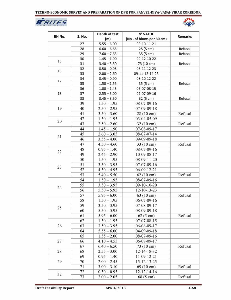
TECHNO-ECONOMIC SURVEY AND PREPARATION OF DPR FOR PANVEL-DIVA-VASAI-VIRAR CORRIDOR
Draft Feasibility Report APRIL, 2013 4-68
BH No. S. No. Depth of test
(m)
N’ VALUE
(No . of blows per 30 cm) Remarks
27 5.55 – 6.00 09-10-11-21
28 6.60 – 6.65 25 (5 cm) Refusal
29 7.60 – 7.65 35 (5 cm) Refusal
15 30 1.45 – 1.90 09-12-10-22
31 3.40 – 3.50 73 (10 cm) Refusal
16 32 0.50 – 0.95 08-11-12-23
33 2.00 – 2.60 09-11-12-14-23
17 34 0.45 – 0.90 08-10-12-22
35 1.50 – 1.55 35 (5 cm) Refusal
18
36 1.00 – 1.45 06-07-08-15
37 2.55 – 3.00 07-07-09-16
38 3.45 – 3.50 32 (5 cm) Refusal
19
39 1.50 – 1.95 08-07-09-16
40 2.50 – 2.95 07-09-09-18
41 3.50 – 3.60 28 (10 cm) Refusal
20 42 1.50 – 1.95 03-04-05-09
43 2.50 – 2.60 32 (10 cm) Refusal
21
44 1.45 – 1.90 07-08-09-17
45 2.60 – 3.05 08-07-07-14
46 3.55 – 4.00 09-09-09-18
47 4.50 – 4.60 33 (10 cm) Refusal
22 48 0.95 – 1.40 08-07-09-16
49 2.45 – 2.90 10-09-08-17
23
50 1.50 – 1.95 08-09-11-20
51 3.50 – 3.95 07-07-09-16
52 4.50 – 4.95 06-09-12-21
53 5.40 – 5.50 62 (10 cm) Refusal
24
54 1.50 – 1.95 08-07-09-16
55 3.50 – 3.95 09-10-10-20
56 5.50 – 5.95 12-10-13-23
57 5.95 – 6.00 63 (10 cm) Refusal
25
58 1.50 – 1.95 06-07-09-16
59 3.50 – 3.95 07-08-09-17
60 5.50 – 5.95 08-09-09-18
61 5.95 – 6.00 62 (5 cm) Refusal
26
62 1.50 – 1.95 07-07-08-15
63 3.50 – 3.95 06-08-09-17
64 5.55 – 6.00 04-09-09-18
27
65 1.55 – 2.00 08-07-09-16
66 4.10 – 4.55 06-08-09-17
67 6.40 – 6.50 73 (10 cm) Refusal
28 68 2.55 – 3.00 12-14-18-32
29
69 0.95 – 1.40 11-09-12-21
70 2.00 – 2.45 15-12-13-25
71 3.00 – 3.10 69 (10 cm) Refusal
32 72 0.50 – 0.95 12-12-14-16
73 2.00 – 2.05 68 (5 cm) Refusal

TECHNO-ECONOMIC SURVEY AND PREPARATION OF DPR FOR PANVEL-DIVA-VASAI-VIRAR CORRIDOR
Draft Feasibility Report APRIL, 2013 4-69
BH No. S. No. Depth of test
(m)
N’ VALUE
(No . of blows per 30 cm) Remarks
74 3.45 – 3.50 73 (5 cm) Refusal
33
75 2.60 – 3.05 09-08-10-18
76 5.50 – 5.95 11-09-16-25
77 6.00 – 6.10 69 (10 cm) Refusal
37
78 1.45 – 1.90 12-15-19-34
79 3.50 – 3.95 09-12-18-30
80 6.00 – 6.45 11-12-16-28
81 7.00 – 7.10 86 (10 cm) Refusal
38
82 1.60 – 2.05 06-07-12-19
83 3.70 – 4.15 11-14-18-32
84 6.20 – 6.30 82 (10 cm) Refusal
39
85 2.90 – 3.35 09-10-10-20
86 6.50 – 6.60 75 (10 cm) Refusal
87 8.10 – 8.15 88 (5 cm) Refusal
50
88 2.00 – 2.45 08-08-15-23
89 4.00 – 4.45 09-12-13-25
90 6.00 – 6.45 12-17-20-37
91 7.00 – 7.10 69 (10 cm) Refusal
51
92 1.00 – 1.45 07-09-10-19
93 3.10 – 3.55 12-13-13-26
94 5.10 – 5.55 10-15-16-31
95 6.00 – 6.05 62 (5 cm) Refusal
55
96 2.00 – 2.45 06-12-09-21
97 4.00 – 4.45 09-15-15-30
98 6.00 – 6.45 12-13-17-30
99 7.00 – 7.30 18-21-33 (5 cm) Refusal
56 100 2.00 – 2.45 13-17-22-39
101 2.90 – 3.00 73 (10 cm) Refusal
57
102 2.00 – 3.45 07-09-12-21
103 4.00 – 4.45 10-12-12-24
104 6.00 – 6.05 77 (5 cm) Refusal
58
105 1.00 – 1.45 09-04-13-17
106 3.00 – 3.45 09-07-07-14
107 5.00 – 5.45 05-09-12-21
108 6.00 – 6.10 72 (10 cm) Refusal
59
109 2.10 – 2.55 07-09-06-15
110 4.00 – 4.45 09-07-07-14
111 5.00 – 5.10 77 (10 cm) Refusal
60
112 2.00 – 2.45 05-03-09-12
113 4.00 – 4.45 09-08-09-17
114 6.00 – 6.45 09-10-12-22
115 7.00 – 7.10 89 (10 cm) Refusal
61
1 2.00 – 2.45 07-09-09-18
2 4.00 – 4.45 11-13-12-25
3 5.00 – 5.45 13-17-19-36
4 5.90 – 6.00 71 (10 cm) Refusal

TECHNO-ECONOMIC SURVEY AND PREPARATION OF DPR FOR PANVEL-DIVA-VASAI-VIRAR CORRIDOR
Draft Feasibility Report APRIL, 2013 4-70
BH No. S. No. Depth of test
(m)
N’ VALUE
(No . of blows per 30 cm) Remarks
67 1 3.00 – 3.60 10-14-18-20-32
2 6.00 – 6.60 12-18-18-15-36
68 1 2.00 – 2.45 10-12-11-23
69 1 2.45 – 3.05 09-12-14-16-26
2 4.80 – 4.90 68 (10 cm) Refusal
70 1 2.00 – 2.45 09-12-12-24
2 4.00 – 4.60 08-07-14-15-21
71 1 2.00 – 2.60 07-08-09-11-17
2 4.00 – 4.60 09-10-10-12-20
79
1 2.00 – 2.60 04-05-06-08-11
2 4.00 – 4.60 04-07-05-08-12
3 6.50 – 7.10 09-08-07-11-15
4 9.50 – 10.10 05-07-09-13-16
5 11.50 – 12.10 09-11-12-15-23
6 13.00 – 13.30 07-14 (10 cm) Refusal
80 1 2.00 – 2.60 07-09-12-15-21
2 4.00 – 4.60 10-12-14-15-26
84 1 2.00 – 2.60 03-05-09-07-14
2 6.00 – 6.60 09-08-13-12-21
85 1 4.00 – 4.60 09-12-13-18-25
86 1 2.00 – 2.60 05-06-08-12-14
87
1 2.00 – 2.60 09-11-11-08-22
2 4.00 – 4.60 11-12-14-13-26
3 6.50 – 7.10 09-07-13-12-20
88
1 1.00 – 1.60 08-07-12-11-19
2 3.00 – 3.60 07-06-09-11-15
3 5.00 – 5.60 06-07-09-08-16
4 6.00 – 6.60 07-05-08-10-13
5 9.00 – 9.60 09-06-09-12-15
6 10.50 – 11.10 08-06-09-11-15
7 12.00 – 12.60 10-14-12-13-26
89
1 2.00 – 2.60 05-05-07-07-12
2 4.00 – 4.60 05-08-07-09-15
3 6.50 – 7.10 09-10-12-11-22
4 9.50 – 10.10 09-13-12-11-25
5 12.00 – 12.60 10-12-14-11-26
6 14.00 – 14.60 09-11-14-13-25
93 1 1.00 – 1.60 10-11-15-12-26
94 1 2.00 – 2.60 09-10-09-11-19
2 4.00 – 4.60 09-10-10-13-20
95 1 2.50 – 3.10 09-10-13-12-23
96 1 2.00 – 2.60 09-08-13-12-21
2 3.90 – 4.00 69 (10 cm) Refusal
111
1 2.00 – 2.60 09-08-12-13-20
2 4.00 – 4.60 10-08-13-10-21
3 6.00 – 6.60 12-13-12-18-25

TECHNO-ECONOMIC SURVEY AND PREPARATION OF DPR FOR PANVEL-DIVA-VASAI-VIRAR CORRIDOR
Draft Feasibility Report APRIL, 2013 4-71
BH No. S. No. Depth of test
(m)
N’ VALUE
(No . of blows per 30 cm) Remarks
4 7.90 – 8.35 12-18-17-35
113
1 2.00 – 2.60 07-07-09-12-16
2 4.00 – 4.60 09-10-10-11-20
3 6.00 – 6.60 09-09-13-12-22
4 8.00 – 8.60 07-07-09-11-16
5 10.00 – 10.60 09-09-14-15-23
6 14.00 – 14.60 11-13-18-13-31
116
1 2.00 – 2.60 07-09-07-10-16
2 4.00 – 4.60 09-10-12-13-22
3 6.00 – 6.60 10-09-11-12-20
4 9.00 – 9.60 09-07-12-10-19
5 12.00 – 12.60 09-11-12-13-23
6 16.00 – 16.60 10-11-13-12-24
4.8 LAND REQUIREMENT
4.8.1 Land will be required for the following Main Components
• Proposed Corridor Structure (including Route Alignment), Station Building,
Platforms, Entry/Exit Structures, Traffic Integration Facilities, Depots, etc.
• Receiving/Traction Sub-stations
• Temporary Construction Depots and work sites
4.8.2 Land for Traffic integration
No land acquisition is proposed exclusively for traffic integration purpose.
4.8.3 Land for Maintenance Depot
About 34.80 Hectares of open land has been proposed for Depot in Kalwar.Intially
depot was being planned at Kharbao, which falls in CRZ area. Alternate location of
depot of estimated area 34.80 hact. has now been proposed along the purposed tracks
between Dunge-Kalwar .
4.8.4 Land for TSS, RSS, ASS and DG Sets
New Kopar TSS has been proposed in the premises of existing DC TSS at Dombivli and it
is noted that Dombivli DC-TSS would be redundant after completion of DC-AC
conversion work. Similarly at existing TSS namely at Panvel, Kharbao and Vasai Road,
required augmentation has been planned. Therefore no fresh procurement of land is
required for TSS purpose.
Table 4.23: Detail of Land Requirement for TSS
S.
No. TSS Station Details
Land
Ownership Area In Sqm
1 TSS-1 Existing TSS at
Panvel
Near Signal
S-31 Rly
Additional transformer
will be located in the

TECHNO-ECONOMIC SURVEY AND PREPARATION OF DPR FOR PANVEL-DIVA-VASAI-VIRAR CORRIDOR
Draft Feasibility Report APRIL, 2013 4-72
S.
No. TSS Station Details
Land
Ownership Area In Sqm
existing TSS
2 TSS-2 Kopar TSS
Approx
600 m
from Kopar
station
Rly
Located inside the
existing premises of
Dombivli DC TSS
3 TSS-3 Existing TSS at
Kharbao* Near 65/18 Rly.
Additional transformer
will be located in the
existing TSS
4 TSS-4 Existing TSS at
Vasai road Existing Rly ---do--
NIL
* Due to DFC alignment passing on East of existing tracks, existing TSS at Kharbao on
east of track is being relocated by DFC on west side of the track.
4.9.5 Land Requirement for Stations and Running Sections
As the entire alignment is proposed either elevated or At-grade, land will be required
for running section.
To the extent possible the Entry and Exit points of stations were planned on the vacant
Rly. land. But, for locating other station facilities such as water tanks, generator room,
fire room etc., land/property acquisition is proposed.
The details of land permanently required for stations and running section are indicated
in the Tables 4.25 and 4.26 respectively.
Table 4.25: Details of Land permanently required for Stations
S.
No Station Chainage
Land
(in sqm)
Owne
r ship
Property
affected Purpose Remarks
1 New
Panvel
1330.918-
1615.00 10371 CIDCO Nil
For entry exit
and station
planning
open
2 Tembode 2343.067-
2619.661 8950 CIDCO
Temp huts
(Adivashi
area)
For entry exit
and station
planning
3 Navade
road
7294.837-
7570.192 6570 Pvt. nil
For entry exit
and station
planning
Open space
4 Pindhar 8713.830-
8758.783 1698 Pvt nil
For entry exit
and station
planning
Marshy land
(aprrox 45
mtr length of
Pvt. land is
required)
5 Nighu 14732.000-
15039.841 4737 Pvt nil
For entry exit
and station
planning
Barren land

TECHNO-ECONOMIC SURVEY AND PREPARATION OF DPR FOR PANVEL-DIVA-VASAI-VIRAR CORRIDOR
Draft Feasibility Report APRIL, 2013 4-73
S.
No Station Chainage
Land
(in sqm)
Owne
r ship
Property
affected Purpose Remarks
6 Narivali 16592.467-
16869.507 4265 Pvt. nil
For entry exit
and station
planning
Barren land
7 Nilaje 19392.665-
19494.29 2175 Pvt.
Boundary of
residential
building
infringing
(area 50.575
sqm.)
For entry exit
and station
planning
Agricultural
land
8 Nandivli
(elev)
24679.265-
24949.265 14765 Pvt.
Store room ,
(G+4)
For entry exit
and station
planning
Agricultural
land
9 Kharbao 43176.201-
43425.585 7732 Pvt Nil
For entry exit
and station
planning
Open place
10 Kaman
Road
51529.455-
51799.455 4662 Pvt. Nil
For entry exit
and station
planning
Hilly terrain
11 Juchandra 57144.226-
57414.226 6869 Pvt. Nil
For entry exit
and station
planning
Paddy land
12 Vasai road 62669.136-
62843.808 2983
Govt
land Nil
For entry exit
and station
planning
V.V.MC area
13 Nalasopara 62669-
66972.520 2028 Pvt.
Shopping
centre(G+1),
temporary
shops, tiled
house
For entry exit
and station
planning
14 Virar 69064.834-
69334.834 1135 Govt. nil
For entry exit
and station
planning
V.V.MC area
Summary of Permanent Land Requirement for Stations
Description Area (in Sqm)
Govt. Land 23439
Pvt. Land 55501
Total 78940

TECHNO-ECONOMIC SURVEY AND PREPARATION OF DPR FOR PANVEL-DIVA-VASAI-VIRAR CORRIDOR
Draft Feasibility Report APRIL, 2013 4-74
Table 4.26: Details of Land permanently required for Running Section
S.
No. Section Chainage
Land
(in sqm)
Owner
ship
Property
affected Remarks
1 Panvel-New
Panvel
864.271-
1127.746 3385 Govt. Nil
CIDCO
Open land
2 Panvel-New
Panvel
1195.729-
1330.918 2473 Govt. Nil
CIDCO
Open land
3 New Panvel-
Tembode
1615.00-
1793.298 4282 Govt. Nil
CIDCO
Open land
4 New Panvel-
Tembode
2193.062-
2343.067 4219 Govt. Nil
CIDCO
Open land
5 Tembode-
kalamboli
3991.384-
4418.121 3527 Govt. Nil FCI land
6 Kalamboli-
Navade Road
5546.465-
5838.688 5598 Govt. Nil FCI land
7 Kalamboli-
Navade Road
5838.688-
5900.000 1145 Govt. Nil FCIland
8 Kalamboli-
Navade Road
5900.00-
6248.401 6011 Govt. Nil FCI land
9 Navade Road-
Pindhar
8621.000-
8713.830 1947 Pvt. Nil Open land
10 Taloja-Nighu 11278.235-
11517.000 4504 Pvt. Nil Open land
11 Taloja-Nighu 11517.000-
11738.202 6847 Pvt. Nil Open land
12 Taloja-Nighu 12043.480-
12126.134 1312 Pvt. Nil
Barren
land
13 Taloja-Nighu 12126.134-
12600 6441 Pvt. Nil
Paddy
land
14 Taloja-Nighu 13800.000-
14481.756 12683 Pvt. Nil
Paddy
land
15 Narivali-Nilaje 17072.385-
17684.444 10837 Pvt. Nil
Barren
land
16 Nilaje-
Nandivali(Elev)
19813.804-
20271.161 2868 Pvt.
1-building
(G+2), 4
house (G+0),
1 U/C
building
(G+2)
Residential
land

TECHNO-ECONOMIC SURVEY AND PREPARATION OF DPR FOR PANVEL-DIVA-VASAI-VIRAR CORRIDOR
Draft Feasibility Report APRIL, 2013 4-75
S.
No. Section Chainage
Land
(in sqm)
Owner
ship
Property
affected Remarks
17 Nilaje-
Nandivali(Elev)
22942.000-
24679.265 37821 Pvt. Nil Open land
18 Nandivali(Elev)-
Kopar (Elev)
24949.265-
25648.000 14913 Pvt.
3-house
(G+0) Open land
19 Kalwar depot 38523-
39900 348000 pvt nil Open land
20 Dunge-Kharbao 43049.916-
43176.201 2634 Pvt. Nil
Paddy
land
21 Kharbao-
Payegaon
43765.822-
44858.043 26911 Pvt. Nil
Paddy
land
22 Kharbao-
Payegaon
44858.043-
44900.000 277 Pvt. Nil
Paddy
land
23 Juchandra-
Vasai road
61567.252-
61970.335 4949 Govt. Nil Salt Pan
24 Juchandra-
Vasai road
61970.335-
62195 2981 Govt. Nil Salt Pan
25 Juchandra-
Vasai road
62195-
62383.182 2185 Pvt
Sai mandir,1-
building(G+2)
26 Vasai road
station
62500-
62575 459 Govt.
On the road
& along the
drain
V.V.M.C
land
27 Vasai Road-
Nalasopara
62972.383-
63045.817 569 Pvt.
Temporary
house Sant
Jalaram
Nagar
Temporary
house
28 Vasai Road-
Nalasopara
65561.608-
65755.50 388 Govt. On the road
V.V.M.C.
land
29 Vasai Road-
Nalasopara
65755.50-
66100.000 2844 Govt.
On the
station road
V.V.M.C.
land
30 Vasai Road-
Nalasopara
66100.000-
66600.000 5319 Govt.
On the
station road
V.V.M.C.
land
31 Vasai Road-
Nalasopara
66600.000-
66882.611 4290 Pvt.
Co-op
societies,
vegetable
shops
&Temporary
shops
Pvt land

TECHNO-ECONOMIC SURVEY AND PREPARATION OF DPR FOR PANVEL-DIVA-VASAI-VIRAR CORRIDOR
Draft Feasibility Report APRIL, 2013 4-76
S.
No. Section Chainage
Land
(in sqm)
Owner
ship
Property
affected Remarks
32 Nalasopara-
Virar
67156-
67265.233 419 Pvt.
Boundary
wall of Co-
Hsg.
Societies.
U/G Sump
etc
Residential
land
33 Nalasopara-
Virar
67265.233-
67732.431 2070 Pvt.
Boundary
wall of Co-
Hsg.
Societies.
Residential
land
34 Nalasopara-
Virar
67732.431-
68237.50 2269 Pvt. Nil Pvt land
35 Nalasopara-
Virar
68400-
69064 4959 Govt. Nil
V.V.M.C
land
36 Virar 69800-
70009 935 Pvt.
Mahanager
park, temp
tiled houses.
Pvt land
Summary of Permanent Land Requirement for running sections
Description Area (in Sqm)
Govt. Land 52539
Pvt. Land 142732
Kalwar depot (Pvt.) 348000
Total land 543271
4.8.6 Temporary Construction Depot
During construction period, construction materials like reinforcing bars, cement, steel
sections, shutters, pre-cast segments etc. are to be stored for elevated corridor from
Nilaje to kopar and from Vasai road to Virar. Therefore, sufficient land is required for
storage of these materials.
Since the area of land being acquired permanently at most of the stations is bare
minimum, the land required for construction depots purpose is identified throughout
the corridor, in the vicinity of the stations on temporary acquisition basis. The areas
proposed for such purpose are indicated in Table 4.27. These sites will be obtained on
lease temporarily for the construction period. After completion of construction, these
will be handed over back to the land owning agency.
About 10 Hac land is proposed for construction depots along the corridor. The
proposed sites are presently vacant. The areas are identified based on availability as
vacant on date. At the time of construction, depending upon the need, area
requirements, the location and size can be reassessed and temporary land acquisitions
can be made accordingly.

TECHNO-ECONOMIC SURVEY AND PREPARATION OF DPR FOR PANVEL-DIVA-VASAI-VIRAR CORRIDOR
Draft Feasibility Report APRIL, 2013 4-77
Table 4.27: Details of Land temporarily required for Construction Depot
S.
No.
Plot
No Section Chainage
Area In
Sqm
Land
Ownership Remarks
1 CD1 Nilaje-Kopar 21500-
22060 55197 Rly.
Rly. boundary marked as
per railway boundary
plan
2 CD2 Juichandra -
Vasai road
59576-
60540 37876 Rly.
Rly. boundary marked as
per railway boundary
plan
3 CD3 Virar 66978-
67157 7291 Rly
Rly. boundary marked as
per railway boundary
plan
Total 100364
4.8.8 Summary of Land Requirements
Abstract of land requirements for different components of corridor are given in Table
4.28. For running sections Govt. land 5.25 hact. and private land 14.27 hact is required.
For stations, Private land 5.55 hact. and Govt land 2.34 hact is required. Private land
34.80 hact is required for the proposed depot at kalwar. All this requirement exclude
land already in possession of Railways.
Govt. Land of 10.00 hact is temporarily required for construction depots for elevated
corridor portion.
Table 4.24: Summary of Permanent Land Requirement
S. No Description Pvt. Land in
SQM
Govt. Land other than
railway in SQM
Total land in
SQM
1 Running
section 142732 52539 195271
2 Kalwar
Depot 348000 - 348000
3 Station area 55501 23439 78940
Total 546233 75978 622211
Say 62.22 Hact
4.9 CONSTRUCTION PLANNING
4.9.1 The construction of proposed suburban corridor between Panvel to Viar is a challenging
task looking to the proximity to running Railway track. This section is mostly At-grade
and some portion is only elevated. The aim of this section is to briefly introduce the
construction methodology proposed for the corridor.

TECHNO-ECONOMIC SURVEY AND PREPARATION OF DPR FOR PANVEL-DIVA-VASAI-VIRAR CORRIDOR
Draft Feasibility Report APRIL, 2013 4-78
4.9.2 General Geology
Mumbai and Navi Mumbai area falls within the region covered by Deccan Volcanic
eruption of lava flows consisting mainly of basalt which took place 65 million year ago.
The volcanic activity was very widespread, covering large area of central India. The
flows of lava and formation of rock are nearly horizontal. In Mumbai area the geology is
slightly different compared to the other portions of Deccan region. The flows consist of
a variety of rocks besides basalt, which are volcanic breecia. Tuffs acidic type like
rhyolite and intermediate rock type like trachyte. Besides these there are also some
Intertrappean sedimentary rock types like shales, mudstones which are inter-bedded
with the regular volcanic types.
The general dips of the strata are also different in Mumbai. The strata dips vary
between 5o to 10o towards the Westerly direction. Besides the bedding joints, there
can be one or two additional prominent joint sets striking North – South and East –
West with moderate to steep dips.
Geology along Alignment
As per the geological profile along the alignment based on borehole investigations,
most of the rock types are expected to be Volcanic Breccra / Tuff variety with strengths
in the range of 5 to 30 Mpa. Some proportions of Basalt are expected with strength in
the range of 20 to 250 Mpa. Some pockets of the sedimentary Interappean rocks
consisting of Shale intercalations can also be expected with strengths in the range of 1
to 20 Mpa. The GT investigation details are submitted in a separate volume.
4.9.3 Overview of Alignment Features
RITES officials made regular visits to the project site to check the existing conditions
along the existing corridor. Detailed survey has been conducted to know the exact
extent of the railway land and also the space available between the railway boundary
and the centre line of extreme track. Based on this detailed survey and the data
collected during various site visits and also from various government organizations, it
has been proposed to divide the corridor into two parts, i.e.
• Elevated
• At-grade
Accordingly, a most economical and technically feasible alignment has been proposed.
The space to construct the elevated viaduct within the Railway’s right of way is not
uniform along the alignment. Due to this reason , the alignment has to cross form east
side to west side or vice versa over the existing tracks due to constraints of land, private
properties, non-availability of roads of adequate width, private properties right on edge
of railway boundary. These special locations have been termed as cross-over and are
tabulated below.
Chainage ( in m) Change of Alignment Remarks
22800-22900 Crosses Panvel-Diva Track and
changes from West to East
Between Nilaje and Koper
Station
25800-25900 Changes from East to West Alignment changes from West

TECHNO-ECONOMIC SURVEY AND PREPARATION OF DPR FOR PANVEL-DIVA-VASAI-VIRAR CORRIDOR
Draft Feasibility Report APRIL, 2013 4-79
to East before Koper Station
60860-61200 Changes from West to East Before Vasai Road Station
The total length of at-grade stretch is about 48.32 Km. The vertical profile is designed
elevated/at-grade between the chainage mentioned in the table below due to
restriction of road width, availability of ROW etc and entry to depot.
Chainage
(in m)
(-140) -
20700
20700 -
26800
26800 -
27125
27125 -
27553
27553-
60250
60250 -
70000
Change of
elevation At grade Elevated At grade Elevated At grade Elevated
4.9.4 Elevated Construction
In view of the prevailing conditions, loading, etc., a typical span length of 30 m has been
proposed all along the corridor. Moreover, since the alignment has to be as far as
possible within the Railway ROW, it is not possible to avoid the existing FOBs and ROBs
running perpendicular to the proposed suburban corridor. Generally a span
configuration of 30 m has been adhered to all along the proposed alignment but it is
only at some locations of ROBs and FOBs that some non standard spans (eg. 25m, 35m
etc.) or special structures has been proposed. The structural design has to be suitable
for live axle load of 18 tonne.
4.9.5 Foundation System
4.9.5.1 Pile Foundation
Considering the space restriction and the assumption that the rock level is
encountered at a depth about 8m below the ground, pile foundation is
proposed with socketing into the rock. Two types of pile foundations are
proposed, depending upon the availability of construction space.
• Multiple Pile
• Monopile
1. Multiple Pile
Bored piles of 1.2m diameter are envisaged. The piles would be arranged in
group of four and the maximum pile cap dimension would be 5.0m x 5.0m.
Moreover, a construction space of at least 8m width would be required for
piling. The multiple pile groups shall be provided only in the stretch where the
aforesaid width is available for construction without any disturbance to the
adjoining structures and Railways operations.
2. Monopile
This type of pile foundation, as the name suggests, consists of a single larger
diameter pile. The diameter of monopile is envisaged to vary from 2m to 2.5m
TECHNO-ECONOMIC SURVEY AND PREPARATION OF DPR FOR PANVEL-DIVA-VASAI-VIRAR CORRIDOR
Draft Feasibility Report APRIL, 2013 4-80
depending on the difference between the rock level and the rail level. The
construction space required would be 5m in width. Monopile is proposed at
locations of space restrictions or to avoid infringement with existing railway
structures and utilities. If, however, at the time of construction, the relocation of
existing structures and shifting of utilities is approved by the railways and the
width for construction of foundation is enough for group of piles, the multiple
pile foundation is preferable.

TE
CH
NO
-EC
ON
OM
IC S
UR
VE
Y A
ND
PR
EP
AR
AT
ION
OF
DP
R F
OR
PA
NV
EL
-DIV
A-V
AS
AI-
VIR
AR
CO
RR
IDO
R
D
ra
ft F
ea
sib
ilit
y R
ep
or
t A
PR
IL,
20
13
4
-81
Fig
ure
4.4
: P
rop
ose
d T
yp
ica
l V
iad
uct
-Su
bst
ruct
ure
(M
ult
iple
pil
e)

TE
CH
NO
-EC
ON
OM
IC S
UR
VE
Y A
ND
PR
EP
AR
AT
ION
OF
DP
R F
OR
PA
NV
EL
-DIV
A-V
AS
AI-
VIR
AR
CO
RR
IDO
R
D
ra
ft F
ea
sib
ilit
y R
ep
or
t A
PR
IL,
20
13
4
-82
Fig
ure
4.5
: P
rop
ose
d T
yp
ica
l V
iad
uct
-Su
bst
ruct
ure
(M
on
op
ile
)

TE
CH
NO
-EC
ON
OM
IC S
UR
VE
Y A
ND
PR
EP
AR
AT
ION
OF
DP
R F
OR
PA
NV
EL
-DIV
A-V
AS
AI-
VIR
AR
CO
RR
IDO
R
D
ra
ft F
ea
sib
ilit
y R
ep
or
t A
PR
IL,
20
13
4
-83
Fig
ure
4.6
: P
rop
ose
d T
yp
ica
l V
iad
uct
-Pil
e F
ou
nd
ati
on
s
AA
PLAN VIEW
BB
VIEW A-A
VIEW B-B

TECHNO-ECONOMIC SURVEY AND PREPARATION OF DPR FOR PANVEL-DIVA-VASAI-VIRAR CORRIDOR
Draft Feasibility Report APRIL, 2013 4-84
4.10 STRUCTURE
The viaduct superstructure will be supported on single cast-in-place RC pier central or
cantilever or portal as required at site.The pier cap is designed and constructed on top
of pier to support bearings under the super structure.
To prevent any accidental impact of any vehicle to pier, a Jersey Shaped crash barrier of
1.0 m height above existing ground level has to be provided all around the pier. A gap
of 25mm has also to be provided in between the crash barrier and outer face of pier at
critical locations of vehicular movement. The shape of upper part of pier has to be so
dimensioned that a required clearance of 5.5m is always available on road side beyond
vertical plane drawn on outer face of crash barrier. In such a situation, the minimum
height of rail above the existing road is about 8.4m.
The longitudinal centre to centre spacing of elastomeric/pot bearing over a pier would
be about 1.8m. The space between the elastomeric bearings will be utilized for placing
the lifting jack required for the replacement of elastomeric bearing. An outward slope
of 1:200 will be provided at pier top for the drainage due to spilling of rainwater, if any.
The transverse spacing between bearings would be approximately 3.2m.The orientation
and dimensions of the piers for the continuous units or steel girder (simply supported
span) have to be carefully selected to ensure minimum occupation at ground level
traffic. Since the vertical and horizontal loads will vary from pier to pier, this will be
catered to by selecting the appropriate structural dimensions.
4.10.1 Pier and Pier Caps
Keeping in mind the aesthetics, the piers for typical viaduct shall be circular, diameter
of which varies from 2.0m to 3.0m depending on the rail, ground and rock level. The
width at the top of the pier cap is kept to be equal to the bottom width of the box
girder and gradually decreases to diameter to pier over a depth of 2.5 m where it meets
the pier. For special bridges, the substructure for side spans is similar to typical piers
whereas, for main span, rectangular hollow pier monolithic with the superstructure has
been adopted. The substructure for the typical viaduct is summarized below:
S. No. RAIL LEVEL/
GROUND LEVEL ECCENTRICITY
TYPE OF
PIER
PIER
DIMENSION
FOUNDATION
TYPE
1. RL-GL ≤ 17m - Standard 2.0m dia. MTP/MP
2. 17m ≤ RL-GL ≤ 21m - Standard 2.5m dia. MTP/MP
3. 21m ≤ RL-GL ≤ 25m - Standard 3.0m dia. MTP/MP
4. RL-GL ≥ 25m - Hollow 4.0m dia.
hollow
Well
Foundation
5. - E ≤ 4m Cantilever 2.5m Square MTP
6. - 4m ≤ E ≤ 6m Cantilever 3.5m Square MTP
(MTP: Multiple Piles; MP: Mono Pile)

TE
CH
NO
-EC
ON
OM
IC S
UR
VE
Y A
ND
PR
EP
AR
AT
ION
OF
DP
R F
OR
PA
NV
EL
-DIV
A-V
AS
AI-
VIR
AR
CO
RR
IDO
R
D
ra
ft F
ea
sib
ilit
y R
ep
or
t A
PR
IL,
20
13
4
-85
Fig
ure
4.7
: P
rop
ose
d T
yp
ica
l V
iad
uct
-Po
rta
l G
en
era
l A
rra
ng
em
en
t

TE
CH
NO
-EC
ON
OM
IC S
UR
VE
Y A
ND
PR
EP
AR
AT
ION
OF
DP
R F
OR
PA
NV
EL
-DIV
A-V
AS
AI-
VIR
AR
CO
RR
IDO
R
D
ra
ft F
ea
sib
ilit
y R
ep
or
t A
PR
IL,
20
13
4
-86
Fig
ure
4.8
: P
rop
ose
d T
yp
ica
l V
iad
uct
-Ca
nti
lev
er
Ge
ne
ral
Arr
an
ge
me
nt

TECHNO-ECONOMIC SURVEY AND PREPARATION OF DPR FOR PANVEL-DIVA-VASAI-VIRAR CORRIDOR
Draft Feasibility Report APRIL, 2013 4-87
4.11 SUPERSTRUCTURE
The superstructure of a large part of the viaduct is proposed to be constructed as closed
box structure See Fig 4.8. This structural shape is the most efficient, stable and torsion
ally rigid structure possible comprises of simply supported spans. However at major
crossing/over or along existing bridge, special steel or continuous unit will be provided.
The standard span c/c of piers of standard simply supported spans constructed by
precast segmental construction technique has been proposed as 30.0m. The usual
segments shall be 3.0m in length except the Diaphragm segments, which shall be 2.0m
each. The other standard spans (c/c of pier) comprises of 33.0m, 27.0m, 24.0m, 21.0m
& 18.0m, which shall be made by removing/adding usual segments of 3.0m each from
the centre of the span.
The dimensions of end diaphragm will be finalized based on simply supported span of
30.0m and the same will be also kept for all simply supported standard span. The top
level of both the end diaphragms of adjoining spans on the same piers is kept same so
that expansion joint can be installed at top and continuity of profile of end diaphragm
on the same pier can be maintained. The arrangement has been selected from
aesthetic considerations.
For major crossing having spans greater than 30.0 m, special units normally of 3 spans
continuous or standard steel girders bridges as per RDSO approved spans have been
envisaged. All these continuous units (in case provided at obligatory location) will be
constructed by cast-in-situ balanced cantilever construction technique using Bridge
Builder of required design at locations where ground supported shuttering is not
possible. The top profile of superstructure of continuous unit (for the full length) will be
retained the same as for standard spans so that evacuation walkway will be available
even in continuous units.
Figure 4.9: Proposed typical Deck Section
4.11.1 Segmental Construction
Precast segmental construction with internal pre-stressing and epoxy coated joints is by
far most preferred technique in fast track projects. In such construction, the match cast
joints at the interface of two segments are provided with shear keys. The casted

TECHNO-ECONOMIC SURVEY AND PREPARATION OF DPR FOR PANVEL-DIVA-VASAI-VIRAR CORRIDOR
Draft Feasibility Report APRIL, 2013 4-88
segment will be transported on trailers and launched in position through launching
girders. The Pre-cast segmental box girder using external unbounded tendon has been
considered has been chosen mainly due to the following advantages.
• Segmental construction is an efficient and economical method for a large range of
span lengths and types of structures. Structures with sharp curves and variable
super elevation can be easily accommodated.
• Segmental construction permits a reduction of construction time as segments may
be manufactured while substructure work proceeds, and assembled rapidly
thereafter.
• Segmental construction protects the environment, as only space required for
foundation and sub-station is required at site. The superstructure is manufactured
at a place away from busy areas and placement of superstructure is done with the
system erected from piers at heights.
• Segments are easy to stack in the casting yard/stacking yard in more than one layer,
thereby saving in requirement of space.
• It is easier to transport smaller segments by road trailers on city roads.
• It is easy to incorporate last minute changes in span configuration if the site
situation so warrants.
• Interference to the traffic during construction is significantly reduced.
• Segmental construction contributes toward aesthetically pleasing structures and
good finishes.
• The overall labour requirement is less than that for conventional methods.
• Better quality control is possible in the casting yard.
• During construction, the technique shows an exceptionally high record of safety.
4.11.2 Launching Scheme of precast Segments
Launching girder is specially designed for launching of segments. The suggested
launching scheme is designed in such a way that initially the launching girder is erected
on pier head at one end of the work. The segments are lifted in sequence and when the
lifting is over; they are dry matched while hanging from the launching girder. After dry
matching, the segments are glued with epoxy and pre-stressed from one end. The
girder is lowered on the temporary / permanent bearings after pre-stressing. The
launching girder then moves over the launched the superstructure shall be constructed
“span by span” sequentially, starting at one end of a continuous stretch and finishing at

TECHNO-ECONOMIC SURVEY AND PREPARATION OF DPR FOR PANVEL-DIVA-VASAI-VIRAR CORRIDOR
Draft Feasibility Report APRIL, 2013 4-89
the other end. Nos. of launching girders may be required so as to work on different
stretches simultaneously to enable completion of the project in time.
The number of “breaks” in the stretch can be identified by no’s of continuous units. The
suggested method of erection will be detailed in drawings to be prepared. The
governing weight of the segments will be of the order of 70 t (to be decided at
appropriate stage). The launching girder envisaged will be slightly greater than two
span lengths. It must be able to negotiate curves in conjunction with temporary
brackets.
Transportation of segments from casting yard to the point of erection will be effected
by appropriately designed low-bedded trailers (tyre-mounted). The segments can be
lifted and erected using erection portal gantry moving on launching girder.
U-girder segments shall be match cast at the casting yard before being transported to
location and erected in position. Post-tensioned cables shall be threaded in-situ and
tensioned from one end. It is emphasized that for precast segmental construction only
one-end pre-stressing shall be used.
The pre-stressing steel and pre-stressing system steel accessories shall be subjected to
an acceptance test prior to their actual use on the works. The tests for the system shall
be as per FIP Recommendations as stipulated in the special specifications. Only multi-
strand jacks shall be used for tensioning of cables. Direct and indirect force
measurement device (e.g. Pressure Gauge) shall be attached in consultation with
system manufacturer.
The Contractor shall be responsible for the proper handling, lifting, storing, transporting
and erection of all segments so that they may be placed in the structure without
damage. Segments shall be maintained in an upright position at all times and shall be
stored, lifted and/or moved in a manner to prevent torsion and other undue stress.
Members shall be lifted, hoisted or stored with lifting devices approved on the shop
drawings.
4.11.3 Segmental built span by span
In order to avoid any disturbance to the rail traffic, it is proposed to launch and erect
the segments from the already erected deck see fig 4.10. The trailer/carrier is placed on
the already erected first deck nearest to the casting yard with the help of a crane and
the segments are rested on the trailer with the help of crane or a cross gantry located
within the casting yard and spanning across the viaduct. The method is as explained
below:
• Move the launching girder to span (N+1).
• Bring segments from span N (already erected deck).
• Glue all the segments together.
• Stress the PT tendons.

TECHNO-ECONOMIC SURVEY AND PREPARATION OF DPR FOR PANVEL-DIVA-VASAI-VIRAR CORRIDOR
Draft Feasibility Report APRIL, 2013 4-90
Time taken to complete erection of one span = 4 to 5 days approximately, depending
upon the delivery of segments, considering ideal conditions.
Figure 4.10: Segmental span by span erection method
4.11.4 Epoxy Bonded Joints and Shear Keys
A minimum compressive stress of 3kg/sqcm shall be provided uniformly over the cross-
section for the closure stress on the epoxied joint until the epoxy has set. The curing
period for application of the compressive stress, method of mixing and application of
epoxy and all related aspects including surface preparation shall be as per approved
manufacturer’s specifications.
The purpose of the epoxy joint, which is about 1mm on each mating surface, shall be to
serve as lubricant during segment positioning, to provide waterproofing of the joints for
durability in service conditions and to provide a seal to avoid cross-over of grout during
grouting of one cable into other ducts.
The epoxy shall be special purpose and meet requirements of relevant provision of FIP
(International Federation of Pre-stressed Concrete). The temporary compressive stress
during the curing period shall be applied by approved external temporary bar pre-
stressing (such as Macalloy or Diwidag bar systems or approved equivalent) span to
next span and the sequences continue.
4.11.5 Reinforcement and Prestressed Steel
It is proposed to use TMT - HYSD 500 steel as reinforcement bars. For pre-stressing
work, low relaxation high tensile steel strands with the configuration 12 T 13 and or 19
K 15 is recommended (confirming to IS:14268).
Span N+1 Span N

TECHNO-ECONOMIC SURVEY AND PREPARATION OF DPR FOR PANVEL-DIVA-VASAI-VIRAR CORRIDOR
Draft Feasibility Report APRIL, 2013 4-91
4.12 SEQUENCE AND METHODOLOGY OF CONSTRUCTION
4.12.1 Elevated Viaduct
4.12.1.1Substructure and Foundation Construction Method (Typical Viaduct)
1. Construction method of Multiple Pile foundation and Substructure
The construction method of Multiple Pile foundation and Substructure is as
explained below:
Stage 1 – Pile rig enters the location from the nearest access.
Stage 2 – Piling rig aligns itself parallel to the longitudinal axis of the alignment
and places itself at the centre of the foundation. The boom of the rig is made
vertical.
Stage 3 – Rotation of piling rig by 45º for drilling of pile 1 (Refer figure 4.32)
Stage 4 – After completing Pile 1, the rig realigns itself parallel to the
longitudinal axis.
Stage 5 – Placing of reinforcement cage for pile 1.
Stage 6 - Concreting of pile 1 upto the cut-off level.
Stage 7 – Repeat stages 1 to 6 and complete the pile group.
Stage 8 – Cutting of piles, placing of starter bars for pier, reinforcement for pile
cap and concreting of pile cap.
Stage 9 – Completion of reinforcement and fixing of Formwork for pier and
concreting of pier.
Stage 10 - Installation and fixing of Formwork for pier cap.
Stage 11 - Casting for pier cap.
2 Construction method of Monopile Pile foundation and Substructure
The construction method of Monopile foundation and Substructure is as
explained below:
Stage 1 – Pile rig enters the location from the nearest access.
Stage 2 – Piling rig aligns itself parallel to the longitudinal axis of the alignment
and places itself at the centre of the foundation.
Stage 3 – Drilling of Pile.
Stage 4 – Placing of reinforcement cage for pile and placing of starter bars for
pier.
Stage 5 - Concreting of pile upto the cutoff level.
Stage 6 – Completion of reinforcement and fixing of Formwork for pier and
concreting of pier.
Stage 7 - Installation and fixing of Formwork for pier cap.
Stage 8 - Casting for pier cap
The Construction method is explained in the following Figures:

TECHNO-ECONOMIC SURVEY AND PREPARATION OF DPR FOR PANVEL-DIVA-VASAI-VIRAR CORRIDOR
Draft Feasibility Report APRIL, 2013 4-92
Figure 4.11: Proposed Piling Rig arrangement at Site
STAGE-1
STAGE-2

TECHNO-ECONOMIC SURVEY AND PREPARATION OF DPR FOR PANVEL-DIVA-VASAI-VIRAR CORRIDOR
Draft Feasibility Report APRIL, 2013 4-93
Figure 4.12: Foundation and Substructure Construction method
STAGE-3 STAGE-4
STAGE-5 STAGE-6
STAGE – 7 & 8

TECHNO-ECONOMIC SURVEY AND PREPARATION OF DPR FOR PANVEL-DIVA-VASAI-VIRAR CORRIDOR
Draft Feasibility Report APRIL, 2013 4-94
Following are some equipment which is used in construction of multipiles and
monopiles.
Figure 4.13: Equipment for construction of multiple and monopile foundation

TECHNO-ECONOMIC SURVEY AND PREPARATION OF DPR FOR PANVEL-DIVA-VASAI-VIRAR CORRIDOR
Draft Feasibility Report APRIL, 2013 4-95
4.14: Substructure and Foundation Construction Method (Typical Via Pile Top
Method)
Alternatively the monopile can be done by Pile Top Method developed by
WIRTH. The principle is as follows:
Compressed air is injected into the drill pipe below water level, slightly above
the cutting head. The air rising and expanding within the drill pipe greatly
reduces the density of the internal fluid column, creating a differential pressure
between the fluid in the drill hole outside and fluid inside the drill pipe. Due to
the higher density of the outer column, the solids pass from the drill hole,
through the suction cutting head opening and rise up through the drill pipe.
Provided the correct air/fluid flow is established within the drill pipe, the airlift
principle is utilized for transporting the solids to the surface.
The amount of differential pressure and thus the conveying capacity depends on
the rate and volume of compressed air injected the depth of injection and the
delivery head. The rig assembly is as shown in the Fig 4.15.
Figure 4.15: Rig Assembly

TECHNO-ECONOMIC SURVEY AND PREPARATION OF DPR FOR PANVEL-DIVA-VASAI-VIRAR CORRIDOR
Draft Feasibility Report APRIL, 2013 4-96
Figure 4.16: Alternative Reverse Drilling Method for Monopile

TECHNO-ECONOMIC SURVEY AND PREPARATION OF DPR FOR PANVEL-DIVA-VASAI-VIRAR CORRIDOR
Draft Feasibility Report APRIL, 2013 4-97
4.12.2 Superstructures Construction Methods (Typical Viaduct)
For the proposed design concept of superstructure, two alternative construction
methods have been proposed and depend on the operability at a particular location.
Two construction methods are proposed which are following
• Segmental built span by span.
• Full precast span.
1. Segmental built span by span
In order to avoid any disturbance to the rail traffic, it is proposed to launch and
erect the segments from the already erected deck. The method is as explained
below:
• Move the launching girder to span (N+1).
• Bring segments from span N (already erected deck).
• Glue all the segments together.
• Stress the PT tendons.
Figure 4.17: Segmental span by span erection method
2. Full Span Precasting
The full span precasting method allows a very fast construction of the
superstructures after completion of the substructures. It uses pre-tensioning, which
is more economical than post-tensioning.
Span N+1 Span N
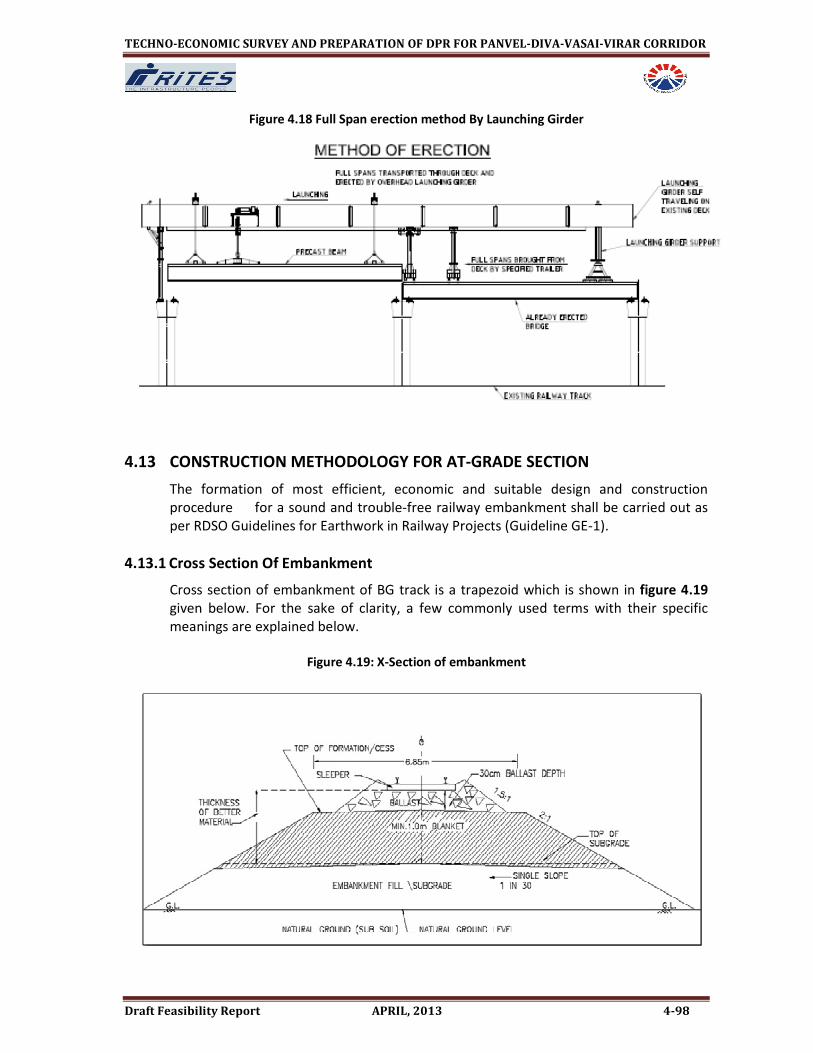
TECHNO-ECONOMIC SURVEY AND PREPARATION OF DPR FOR PANVEL-DIVA-VASAI-VIRAR CORRIDOR
Draft Feasibility Report APRIL, 2013 4-98
Figure 4.18 Full Span erection method By Launching Girder
4.13 CONSTRUCTION METHODOLOGY FOR AT-GRADE SECTION
The formation of most efficient, economic and suitable design and construction
procedure for a sound and trouble-free railway embankment shall be carried out as
per RDSO Guidelines for Earthwork in Railway Projects (Guideline GE-1).
4.13.1 Cross Section Of Embankment
Cross section of embankment of BG track is a trapezoid which is shown in figure 4.19
given below. For the sake of clarity, a few commonly used terms with their specific
meanings are explained below.
Figure 4.19: X-Section of embankment

TECHNO-ECONOMIC SURVEY AND PREPARATION OF DPR FOR PANVEL-DIVA-VASAI-VIRAR CORRIDOR
Draft Feasibility Report APRIL, 2013 4-99
i. Sub-soil: Soil of natural ground below sub grade.
ii. Sub-grade: It is part of embankment/cutting provided above subsoil by
borrowed soil of suitable quality up to bottom of blanket/ballast.
iii. Blanket: Blanket is a layer of specified coarse, granular material of designed
thickness provided over full width of formation between sub grade and ballast.
iv. Ballast: Crushed stones with desired specifications placed directly below the
sleepers.
v. Formation Top: Boundary between ballast and top of blanket or sub grade
(where blanket layer is not provided).
vi. Cess: It is part of top of formation from toe of ballast to edge of formation.
vii. Formation: It is a general term referring to the whole of blanket, sub-grade and
sub-soil.
viii. Track Foundation: Constitutes ballast, blanket and sub grade, which is placed /
exist below track structure to transmit load to subsoil.
4.13.2 Design of Railway Formation
In order to construct a formation that gives trouble free service under the most adverse
conditions of loading, maintenance, and weather, it is necessary that
i. Sub-grade in bank or cutting is structurally sound so as not to fail in shear strength
under its own load and live loads and
ii. Secondly, any settlement due to compaction and consolidation in sub-grade and
subsoil should be within the permissible limits.
4.13.2.1 Various Aspects of Designing a Sub-Grade & Subsoil
Sub grade should be designed to be safe against shear failure and large
deformations. Adequacy of subsoil against shear strength and settlement should
also be examined.
Following are the some aspects that should be considered when designing a
sub-grade and subsoil.
• Deficient shear strength of sub-grade or sub-soil leads to bearing capacity failure
of sub-grade, Interpenetration failure or mud pumping failure and slope failure (
if factor of safety against slope stability is not adequate). Therefore, sub
grade/subsoil should be designed to ensure not to allow any shear failure.
• Large deformation without shear strength failures of soil can be due to poor
compaction during construction and consolidation (primary and secondary) of
sub grade and/or sub-soil and settlement as well as heave due to shrinking and
swelling characteristics of sub grade and/or sub-soil. The swelling and shrinkage
characteristics of sub-soil shall be significant in cases where bank height is less
than 1m or it is in cutting. These aspects should be taken into account at the
time of construction to avoid large settlement causing maintenance problems
and leading to formation failure.

TECHNO-ECONOMIC SURVEY AND PREPARATION OF DPR FOR PANVEL-DIVA-VASAI-VIRAR CORRIDOR
Draft Feasibility Report APRIL, 2013 4-100
• Top width of formation should be adequate enough to accommodate track laid
with concrete sleepers and standard ballast section and have minimum 900mm
cess width on either side. It should be regulated in accordance with extant
instructions of Railway Board. Additional width of formation will have to be
provided to cater for increase in extra ballast on outside of curves and extra
clearance required on double line on account of super-elevation etc.
• Adequate drainage must be ensured for the worst in service conditions. The top
of formation should have cross slope of 1 in 30 from centre of track towards
both sides for single line and from one end towards cess /drain side (single
slope) in multiple lines.
• The design should provide for a suitable and cost-effective erosion control
system considering soil matrix, topography and hydrological conditions.
• It will be necessary to keep borrow pits sufficiently away from the toe of the
embankments to prevent base failures due to lateral escapement of the soil. The
distance of borrow pit from the bank will have to be decided in each case on its
merits. Existing borrow pits, close to toe of bank may be filled or its depth
should be taken into account in analyzing slope stability of the bank.
• In the case of embankments / cuttings in highly cohesive clayey soils, special
treatment may be necessary to ensure a stable formation. Such measures will
have to be determined after thorough investigation and study of the soil
properties.
• Special investigation will also be necessary in regard to high fill construction on
swampy ground or marshy lands and deep cuttings.
• In case of all new construction, minimum height of embankment should not be
less than one meter to ensure proper drainage, avoid organic matters and
trespassing.
• Soils prone to liquefaction falling in gradation zone and having coefficient of
uniformity, Cu < 2 should be adequately designed to take care of this.
4.13.3 Materials For Construction
Construction of embankment is to be carried out normally with soil available in nearby
area with proper design of slope and desired bearing capacity. However, there are
some soils, which are not normally suitable to be used in construction of new lines as
detailed below

TECHNO-ECONOMIC SURVEY AND PREPARATION OF DPR FOR PANVEL-DIVA-VASAI-VIRAR CORRIDOR
Draft Feasibility Report APRIL, 2013 4-101
• Soils to be normally avoided are organic clays, organic silts, peat, chalks, dispersive soils,
poorly graded gravel and sand with uniformity coefficient less than 2 and clays and silts
of high plasticity (CH & MH) in top 3m of embankment.
• Some typical situations, as given below, may arise when in construction of formation
such unsuitable types of soils (given above) are not possible to be avoided for
economical or any other reason, then Railway may consult RDSO to decide special
investigations and other measures to formulate suitable scheme of construction.
i. Cuttings passing through unsuitable soils, shales and soft rocks which become
muddy after coming into contact with water.
ii. Construction of embankment on subsoil of unsuitable types of soils.
iii. Use of CH & MH type of soils even in top 3m of embankment.
4.13.4 Execution of Formation Earthwork
Before taking up of actual execution of work, detailed drawings need to be prepared for
the entire length of the project to give alignment, formation levels, formation width at
ground level, cross sections of catch water drains & side drains, cross section & levels of
sub grade, blanket levels, etc. to facilitate smooth execution at site. Execution of work
has to be carried out in systematic manner so as to construct formations of satisfactory
quality which would give trouble free service. The activities and adoption of good
practices involved in execution of earthwork are covered under following headings
a) Preliminary works
b) General aspects
c) Compaction of earth work
d) Placement of Back-Fills on Bridge Approaches and Similar Locations
e) Drainage Arrangement in Bank/Cutting
f) Erosion control of slopes on banks & cuttings
g) Other aspects
4.13.4.1 Other Aspects of Construction of Earthwork
4.13.4.1.1 Execution of Earthwork- General Aspects
• The spreading of material in layers of desired thickness over the entire width of
embankment should be done by mechanical means and finished by a motor
grader. The motor grader blade shall have hydraulic control suitable for initial
adjustment and maintain the same so as to achieve the slope and grade.
• Thickness of layer is decided based on field compaction trials. However, as a
good practice thickness of layer should be generally kept as 300 mm for fill
material and 250 mm for blanket material in loose state before compaction.
• If natural moisture content (NMC) of the soil is less than the OMC, calculated
amount of water based on the difference between OMC & NMC and quantity of

TECHNO-ECONOMIC SURVEY AND PREPARATION OF DPR FOR PANVEL-DIVA-VASAI-VIRAR CORRIDOR
Draft Feasibility Report APRIL, 2013 4-102
earthwork being done at a time, should be added with sprinkler attached to
water tanker and mixed with soil by motor grader or by other means for
obtaining uniform moisture content. When soil is too wet, it is required to be
dried by aeration to reduce moisture content near to OMC. Efforts should be
made to keep moisture content level of the soil in the range of OMC ± 2% at the
time of compaction.
• Fill shall be placed and compacted in layers of specified thickness. The rate of
progress should be, as far as possible, uniform so that the work is completed to
final level almost at the same time.
• The rolling for compaction of fill material should commence from edges towards
center with minimum overlap of 200 mm between each run of the roller. In final
pass, roller should simply move over the surface without vibration so that top
surface is properly finished.
• Extra bank width of 500 mm on either side shall be rolled to ensure proper
compaction at the edges. The extra soil would be cut and dressed to avoid any
loose earth at the slopes. This should preferably be done with help of grade
cutter.
• At the end of the working day, fill material should not be left uncompacted. Care
should be taken during rolling to provide suitable slope on top of the bank to
facilitate quick shedding of water and avoid ponding on formation.
• During construction of formation, there may be rainfall to the extent that rain
cuts may develop on the surface of formation due to erosion of soil. Care should
be taken that these rain cuts are not allowed to develop wide and deep
otherwise these locations will remain weak spots. Provisions should be made in
contract conditions to attend / repair such rain cuts, as a regular measure.
• Top of the formation should be finished to cross slope of 1 in 30 from one end to
other towards cess/drain in multiple lines and from center of formation to both
sides in single line.
• Once the top surface of the formation has been finished to proper slope and
level, movement of material vehicle for transportation of ballast, sleepers etc.
should be avoided, these movements will cause development of unevenness,
ruts on the surface which will accumulate water and weaken the formation. The
methodology of transportation of P. Way material needs to be planned.
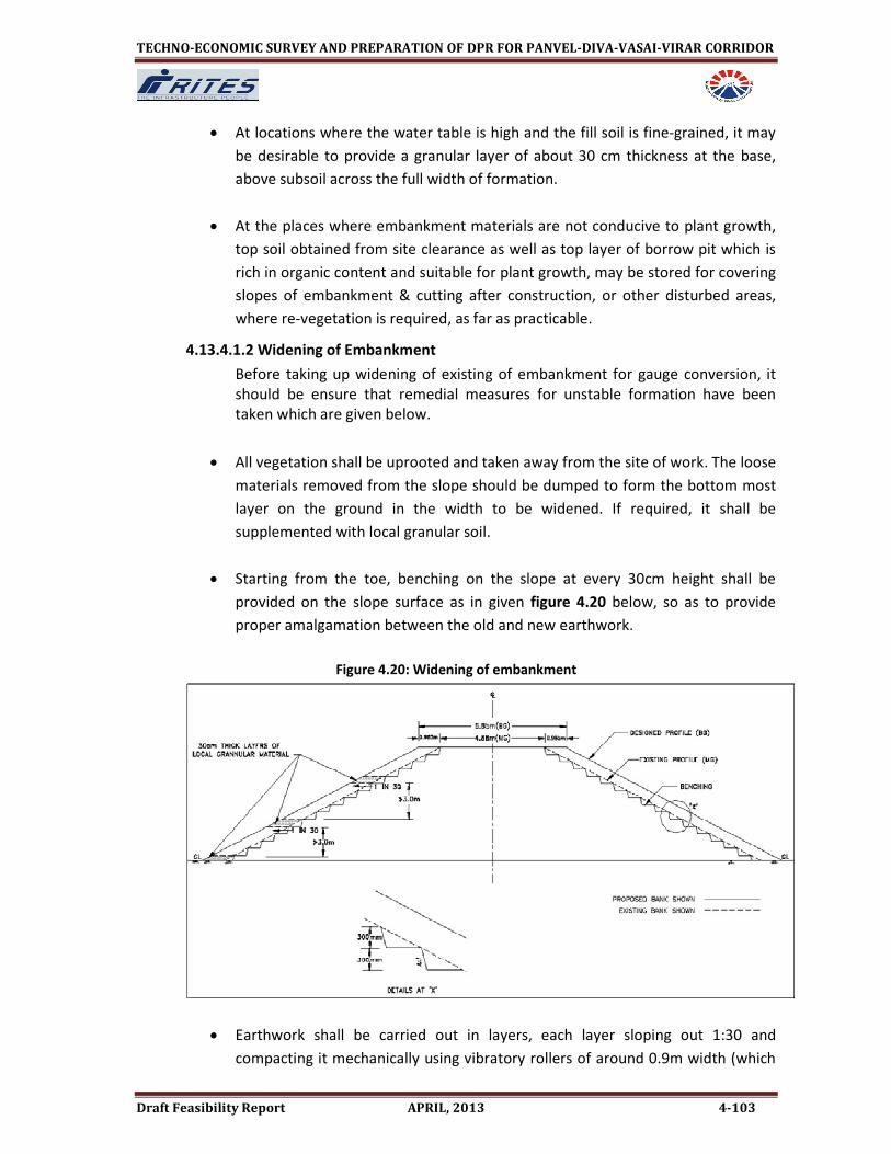
TECHNO-ECONOMIC SURVEY AND PREPARATION OF DPR FOR PANVEL-DIVA-VASAI-VIRAR CORRIDOR
Draft Feasibility Report APRIL, 2013 4-103
• At locations where the water table is high and the fill soil is fine-grained, it may
be desirable to provide a granular layer of about 30 cm thickness at the base,
above subsoil across the full width of formation.
• At the places where embankment materials are not conducive to plant growth,
top soil obtained from site clearance as well as top layer of borrow pit which is
rich in organic content and suitable for plant growth, may be stored for covering
slopes of embankment & cutting after construction, or other disturbed areas,
where re-vegetation is required, as far as practicable.
4.13.4.1.2 Widening of Embankment
Before taking up widening of existing of embankment for gauge conversion, it
should be ensure that remedial measures for unstable formation have been
taken which are given below.
• All vegetation shall be uprooted and taken away from the site of work. The loose
materials removed from the slope should be dumped to form the bottom most
layer on the ground in the width to be widened. If required, it shall be
supplemented with local granular soil.
• Starting from the toe, benching on the slope at every 30cm height shall be
provided on the slope surface as in given figure 4.20 below, so as to provide
proper amalgamation between the old and new earthwork.
Figure 4.20: Widening of embankment
• Earthwork shall be carried out in layers, each layer sloping out 1:30 and
compacting it mechanically using vibratory rollers of around 0.9m width (which

TECHNO-ECONOMIC SURVEY AND PREPARATION OF DPR FOR PANVEL-DIVA-VASAI-VIRAR CORRIDOR
Draft Feasibility Report APRIL, 2013 4-104
are available in the market), 6 to 8 passes of such rollers shall usually suffice
provide the compaction to the specified level.
• The width of each layer of earthwork shall be in excess by 300mm of the
designed profile to enable compaction near the edges. The excess width,
thereafter, cut and dressed, so as to achieve the required bank profile.
• Earthwork shall be completed upto designed formation level keeping due
allowance for the blanket if need be.
4.13.4.1.3 Raising of Existing Formation
After widening of the bank to the level of the existing formation, raising shall be
done as under:
• Raising less than 150mm shall be done with ballast, restricting overall thickness
to 350mm.
• Raising from 150mm to 1000mm, the existing ballast shall be taken out under
suitable speed restriction and raising should be done in suitable steps with the
material as per specification of blanket material, preferably that of upper
blanket layer. After raising to the desired level, clean ballast shall be inserted.
• Raising of more than 1000mm, under traffic, would not be cost effective and it
may be desirable to lay a detour for passage of traffic temporarily. Final decision
shall, however, be based on economic considerations.
4.13.4.1.4 Earthwork in New Detours
To facilitate easing out of existing sharp curves, change of gradients and
rebuilding of important bridges, new detours shall be necessary. Design and
construction of such detours shall be carried out in accordance with these
provisions in the Guidelines.
4.13.4.1.5 Construction Equipments for Execution of Earthwork
Any manual methods of construction cannot achieve the desired quality of
earthwork. It would be necessary to deploy modern equipments such as
earthmover, motor graders, scraper, dumpers, mobile water sprinklers,
vibratory rollers, sheep foot rollers etc. as per need, on all projects, so that the
quality of work is as per laid down standards. It would be desirable to maintain
records of work done by various equipments at a particular site to assess the
output and quality control.
4.13.4.1.6 Construction of New Formation over Soft Compressible Sub-soil:
Various methods such as i) pre- loading and stage construction, ii) installation of
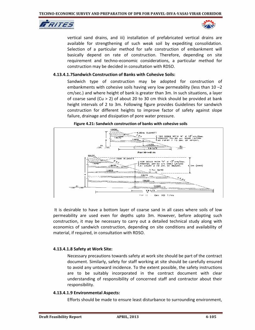
TECHNO-ECONOMIC SURVEY AND PREPARATION OF DPR FOR PANVEL-DIVA-VASAI-VIRAR CORRIDOR
Draft Feasibility Report APRIL, 2013 4-105
vertical sand drains, and iii) installation of prefabricated vertical drains are
available for strengthening of such weak soil by expediting consolidation.
Selection of a particular method for safe construction of embankment will
basically depend on rate of construction. Therefore, depending on site
requirement and techno-economic considerations, a particular method for
construction may be decided in consultation with RDSO.
4.13.4.1.7Sandwich Construction of Banks with Cohesive Soils:
Sandwich type of construction may be adopted for construction of
embankments with cohesive soils having very low permeability (less than 10 –2
cm/sec.) and where height of bank is greater than 3m. In such situations, a layer
of coarse sand (Cu > 2) of about 20 to 30 cm thick should be provided at bank
height intervals of 2 to 3m. Following figure provides Guidelines for sandwich
construction for different heights to improve factor of safety against slope
failure, drainage and dissipation of pore water pressure.
Figure 4.21: Sandwich construction of banks with cohesive soils
It is desirable to have a bottom layer of coarse sand in all cases where soils of low
permeability are used even for depths upto 3m. However, before adopting such
construction, it may be necessary to carry out a detailed technical study along with
economics of sandwich construction, depending on site conditions and availability of
material, if required, in consultation with RDSO.
4.13.4.1.8 Safety at Work Site:
Necessary precautions towards safety at work site should be part of the contract
document. Similarly, safety for staff working at site should be carefully ensured
to avoid any untoward incidence. To the extent possible, the safety instructions
are to be suitably incorporated in the contract document with clear
understanding of responsibility of concerned staff and contractor about their
responsibility.
4.13.4.1.9 Environmental Aspects:
Efforts should be made to ensure least disturbance to surrounding environment,

TECHNO-ECONOMIC SURVEY AND PREPARATION OF DPR FOR PANVEL-DIVA-VASAI-VIRAR CORRIDOR
Draft Feasibility Report APRIL, 2013 4-106
to the extent possible. Wherever, there has been disturbance due to large scale
construction, efforts need to make to improve the surroundings and
environment by way of massive group plantation, so as to restore the area.
Rules and regulations of the government in vogue, in regard to the environment,
need to be followed.
4.14 CONSTRUCTION METHODOLOGY FOR ELEVATED STATIONS
Figure 4.22-Section at Elevated Station Location
The steps for construction of elevated station are as follows:
• Construct the foundation and pier upto the concourse level for typical viaduct.
Foundation is combined for the station column and the viaduct pier and hence
consists of 6 piles of 1.2m diameter.
• Place the form work for longitudinal beam connecting the station columns and pour
concrete.
• Bring the precast cantilever beams from the casting yard.
• Erect the beam in position with the help of cranes during the night so that the
construction activities do not disrupt railway operations and the road traffic.
• Stress the prestressing tendons and stitch the joint.
• After completing the erection of the beams for at least two consecutive grids, place
the self supporting formwork for the construction of concourse slab.

TECHNO-ECONOMIC SURVEY AND PREPARATION OF DPR FOR PANVEL-DIVA-VASAI-VIRAR CORRIDOR
Draft Feasibility Report APRIL, 2013 4-107
• After completion of concourse place the form work for construction of staircases
etc. Supported by concourse slab and columns from concourse to platform.
Complete the construction of station elements.
• Viaduct is constructed similar to the standard viaduct and progresses with the
construction of the station.
Figure 4.23: Plan View of typical foundation for elevated station
VIADUCT PIER
STATION COLUMN
UPTO CONCOURSE
STATION COLUMN
UPTO CONCOURSE
TRAFFIC DIRECTION
1000 3000 3000 10002500
1000
1000
Figure 4.24: Example of construction of slab by self supporting form work
The sequence of construction will depend upon land acquisition from various
authorities and contractor’s work schedule.
4.14.1 Construction of the Station
4.14.1.1 Elevated Station
It is proposed to construct the elevated stations with elevated concourse over the to
minimize land acquisition. To keep the rail level low, it is proposed not to take viaduct
through the stations. Thus a separate structural configuration is required (although this
may necessitate the break in the launching operations at each station locations).
Sub-structure for the station portion will also be similar to that of viaduct and will be
carried out in the same manner. However, there will be single viaduct column in the

TECHNO-ECONOMIC SURVEY AND PREPARATION OF DPR FOR PANVEL-DIVA-VASAI-VIRAR CORRIDOR
Draft Feasibility Report APRIL, 2013 4-108
station area, which will be located on the median and support the concourse girders by
a cantilever arm so as to eliminate the columns on the right-of-way.
Super-structure will consist of precast girders for supporting the track structure and I
Girder/Double T Girders for supporting the platform and concourse areas. A pre-cast or
cast in situ prestressed cross girder will be required over the middle piers for supporting
platform structure. Box shaped in situ prestressed cantilever cross girders are planned
for supporting the concourse girders and escalators at mezzanine level. All the
members will be pre-cast in a construction depot and launched at site through cranes.
4.14.1.2 At Grade Corridor
Ballast less track is proposed to be laid over prepared foundation elements as per
standard specifications.