4-m nwo telescope design - new worldsnewworlds.colorado.edu/documents/asmcs_report/nwo... ·...
TRANSCRIPT

4-m NWO Telescope Design
Steve Kendrick
Ball Aerospace & Technologies Corp.
4/15/2009 NWO Telescope Design 2
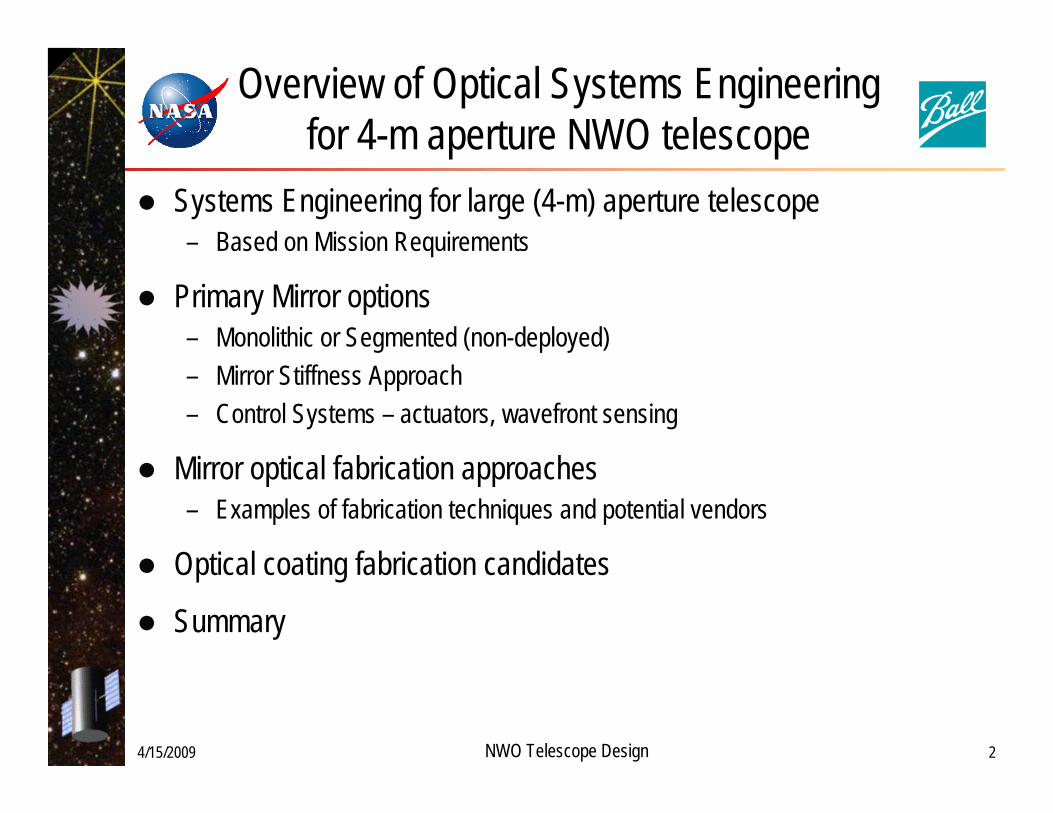
Overview of Optical Systems Engineering for 4-m aperture NWO telescope
Systems Engineering for large (4-m) aperture telescope– Based on Mission Requirements
Primary Mirror options– Monolithic or Segmented (non-deployed)– Mirror Stiffness Approach – Control Systems – actuators, wavefront sensing
Mirror optical fabrication approaches– Examples of fabrication techniques and potential vendors
Optical coating fabrication candidates
Summary

4/15/2009 NWO Telescope Design 3
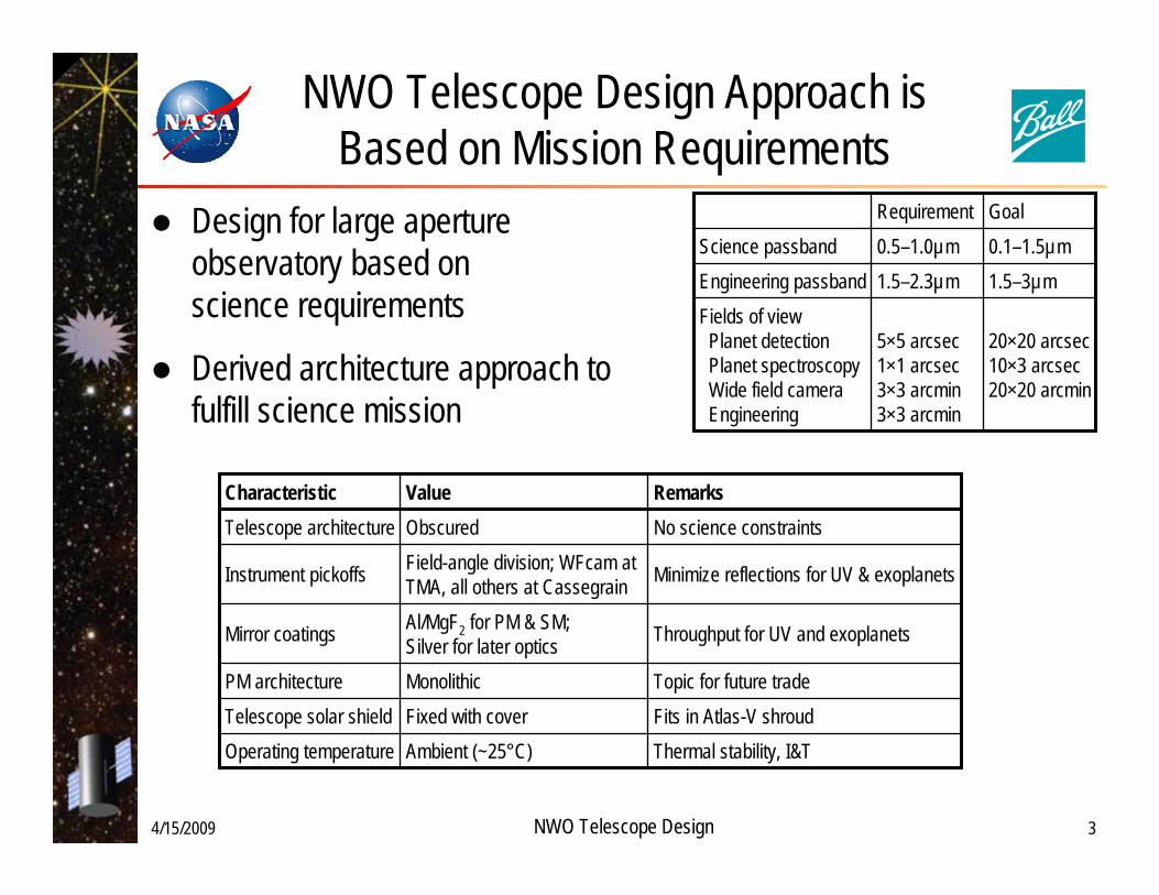
NWO Telescope Design Approach is Based on Mission Requirements
Design for large aperture observatory based on science requirements
Derived architecture approach to fulfill science mission
5×5 arcsec1×1 arcsec3×3 arcmin3×3 arcmin
1.5–2.3µm 0.5–1.0µmRequirement
20×20 arcsec10×3 arcsec20×20 arcmin
Fields of viewPlanet detectionPlanet spectroscopyWide field cameraEngineering
1.5–3µmEngineering passband0.1–1.5µmScience passbandGoal
Throughput for UV and exoplanetsAl/MgF2 for PM & SM; Silver for later opticsMirror coatings
RemarksValueCharacteristic
Ambient (~25°C)Fixed with coverMonolithic
Field-angle division; WFcam at TMA, all others at Cassegrain
Obscured
Thermal stability, I&TFits in Atlas-V shroudTopic for future trade
Minimize reflections for UV & exoplanets
No science constraints
Operating temperatureTelescope solar shieldPM architecture
Instrument pickoffs
Telescope architecture

4/15/2009 NWO Telescope Design 4
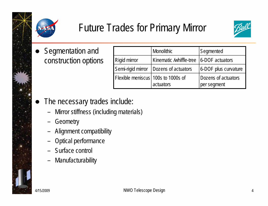
Future Trades for Primary Mirror
Segmentation and construction options
The necessary trades include:– Mirror stiffness (including materials)– Geometry – Alignment compatibility– Optical performance– Surface control– Manufacturability
Dozens of actuators per segment
100s to 1000s of actuators
Flexible meniscus6-DOF plus curvatureDozens of actuatorsSemi-rigid mirror6-DOF actuatorsKinematic /whiffle-treeRigid mirrorSegmentedMonolithic

4/15/2009 NWO Telescope Design 5
Manufacturing issues affecting cost, complexity, and performance
ULE® and Zerodur®
– Both capable of 4 m monolith– Some differences in manufacturing and lightweighting techniques
Silicon Carbide (SiC)– Lack of heritage for achieving visible-light quality– Domestic facilities up to about 1.8 to 2-m diameter
Optical Coating chamber limitations– Only one domestic chamber identified that can coat larger than 3-m

4/15/2009 NWO Telescope Design 6
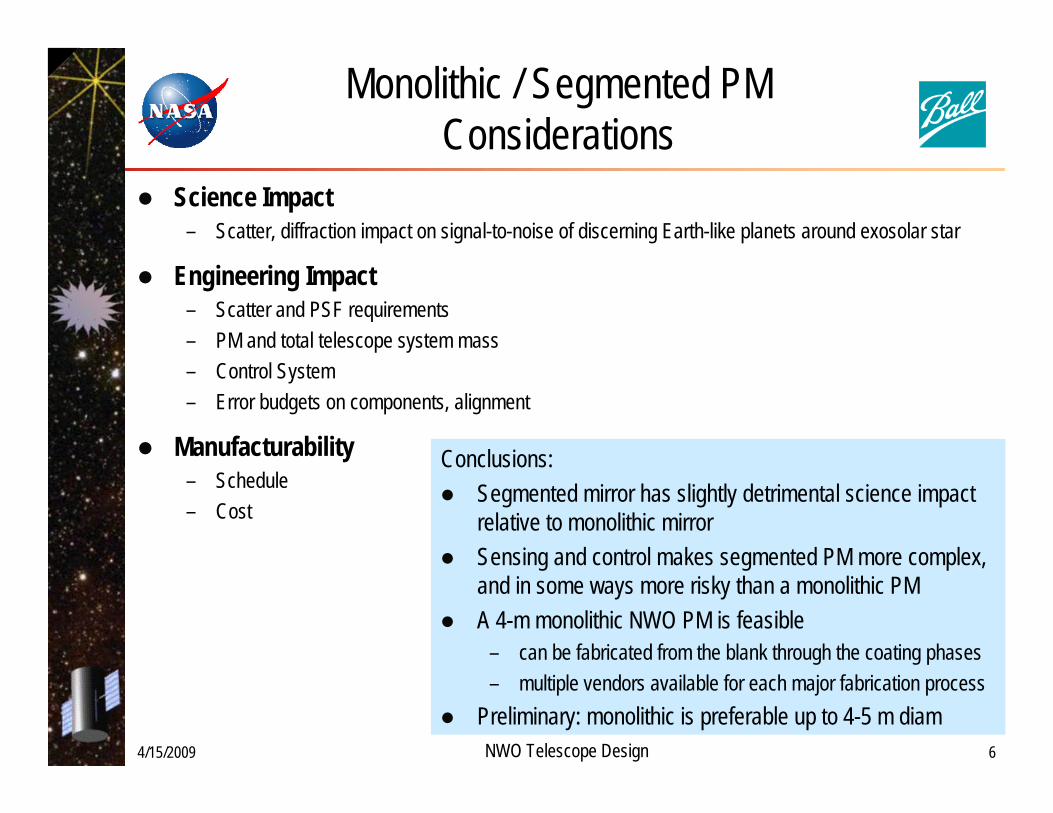
Monolithic / Segmented PM Considerations
Science Impact– Scatter, diffraction impact on signal-to-noise of discerning Earth-like planets around exosolar star
Engineering Impact– Scatter and PSF requirements– PM and total telescope system mass– Control System– Error budgets on components, alignment
Manufacturability– Schedule– Cost
Conclusions:Segmented mirror has slightly detrimental science impact relative to monolithic mirrorSensing and control makes segmented PM more complex, and in some ways more risky than a monolithic PMA 4-m monolithic NWO PM is feasible
– can be fabricated from the blank through the coating phases – multiple vendors available for each major fabrication process
Preliminary: monolithic is preferable up to 4-5 m diam

4/15/2009 NWO Telescope Design 7
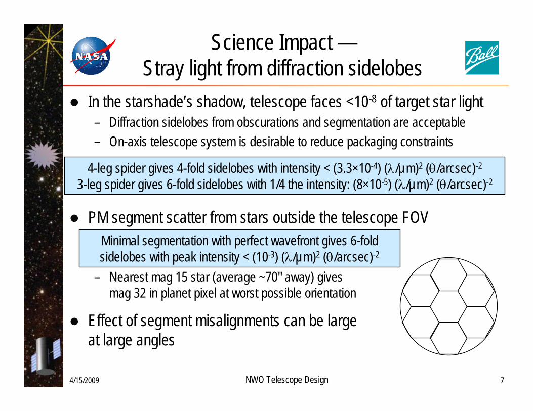
Science Impact —Stray light from diffraction sidelobes
In the starshade’s shadow, telescope faces <10-8 of target star light– Diffraction sidelobes from obscurations and segmentation are acceptable– On-axis telescope system is desirable to reduce packaging constraints
PM segment scatter from stars outside the telescope FOV
– Nearest mag 15 star (average ~70" away) gives mag 32 in planet pixel at worst possible orientation
Effect of segment misalignments can be large at large angles
4-leg spider gives 4-fold sidelobes with intensity < (3.3×10⁻⁴) (λ/µm)2 (θ/arcsec)-2
3-leg spider gives 6-fold sidelobes with 1/4 the intensity: (8×10⁻⁵) (λ/µm)2 (θ/arcsec)-2
Minimal segmentation with perfect wavefront gives 6-fold sidelobes with peak intensity < (10-3) (λ/µm)2 (θ/arcsec)-2
4/15/2009 NWO Telescope Design 8
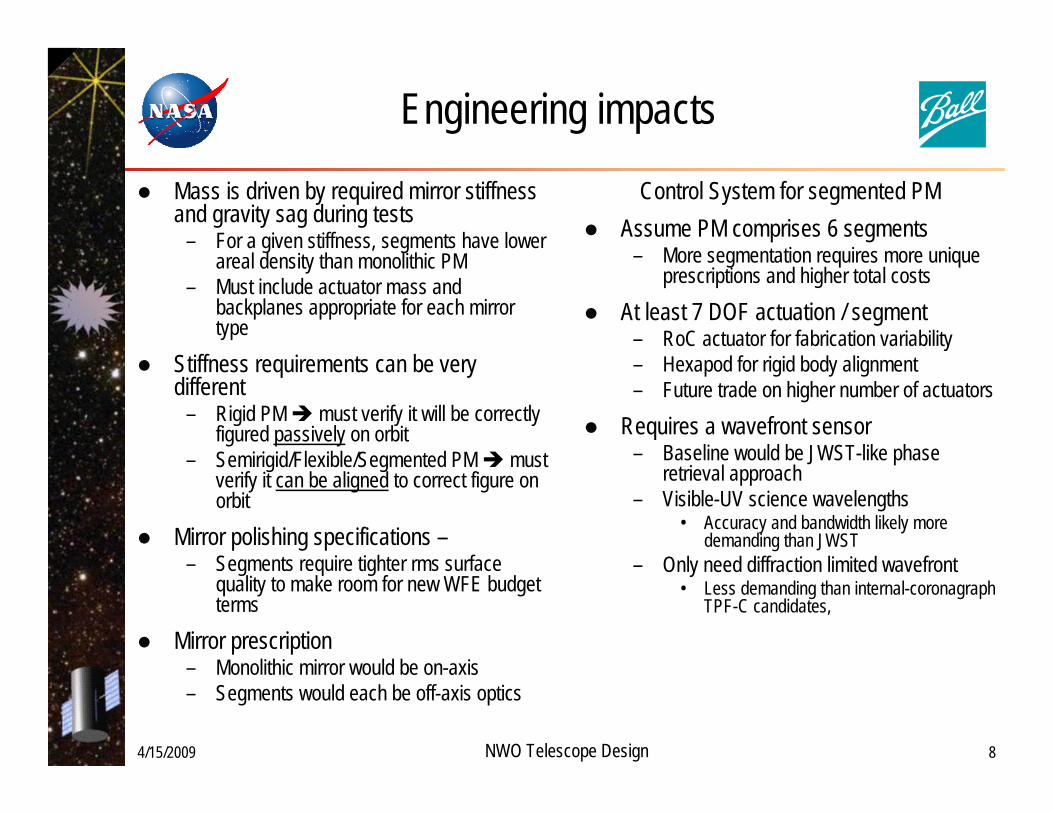
Engineering impacts
Mass is driven by required mirror stiffness and gravity sag during tests
– For a given stiffness, segments have lower areal density than monolithic PM
– Must include actuator mass and backplanes appropriate for each mirror type
Stiffness requirements can be very different
– Rigid PM must verify it will be correctly figured passively on orbit
– Semirigid/Flexible/Segmented PM must verify it can be aligned to correct figure on orbit
Mirror polishing specifications –– Segments require tighter rms surface
quality to make room for new WFE budget terms
Mirror prescription– Monolithic mirror would be on-axis– Segments would each be off-axis optics
Control System for segmented PMAssume PM comprises 6 segments
– More segmentation requires more unique prescriptions and higher total costs
At least 7 DOF actuation / segment– RoC actuator for fabrication variability– Hexapod for rigid body alignment– Future trade on higher number of actuators
Requires a wavefront sensor– Baseline would be JWST-like phase
retrieval approach– Visible-UV science wavelengths
• Accuracy and bandwidth likely more demanding than JWST
– Only need diffraction limited wavefront • Less demanding than internal-coronagraph
TPF-C candidates,

4/15/2009 NWO Telescope Design 9
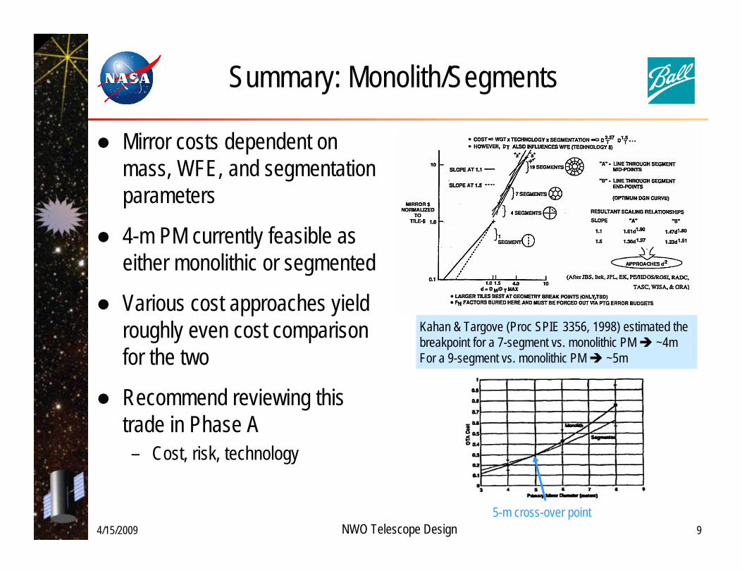
Summary: Monolith/Segments
Mirror costs dependent on mass, WFE, and segmentation parameters
4-m PM currently feasible as either monolithic or segmented
Various cost approaches yield roughly even cost comparison for the two
Recommend reviewing this trade in Phase A– Cost, risk, technology
Kahan & Targove (Proc SPIE 3356, 1998) estimated the breakpoint for a 7-segment vs. monolithic PM ~4m For a 9-segment vs. monolithic PM ~5m
5-m cross-over point

Manufacturability
Substrate Material – Zerodur and ULE blanks can be made at 4m sizeLightweighting – Can be performed on 4-m optics by several vendors Polishing – Can be performed on 4-m optics by several vendorsOptical coating – One vendor identified in continental US for 4-m optics

4/15/2009 NWO Telescope Design 11
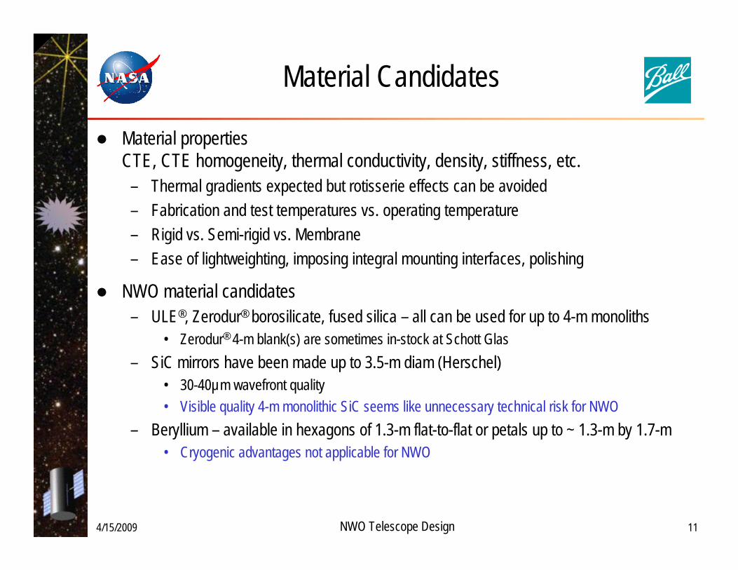
Material Candidates
Material propertiesCTE, CTE homogeneity, thermal conductivity, density, stiffness, etc.
– Thermal gradients expected but rotisserie effects can be avoided– Fabrication and test temperatures vs. operating temperature– Rigid vs. Semi-rigid vs. Membrane– Ease of lightweighting, imposing integral mounting interfaces, polishing
NWO material candidates– ULE®, Zerodur® borosilicate, fused silica – all can be used for up to 4-m monoliths
• Zerodur® 4-m blank(s) are sometimes in-stock at Schott Glas– SiC mirrors have been made up to 3.5-m diam (Herschel)
• 30-40µm wavefront quality• Visible quality 4-m monolithic SiC seems like unnecessary technical risk for NWO
– Beryllium – available in hexagons of 1.3-m flat-to-flat or petals up to ~ 1.3-m by 1.7-m • Cryogenic advantages not applicable for NWO

4/15/2009 NWO Telescope Design 12
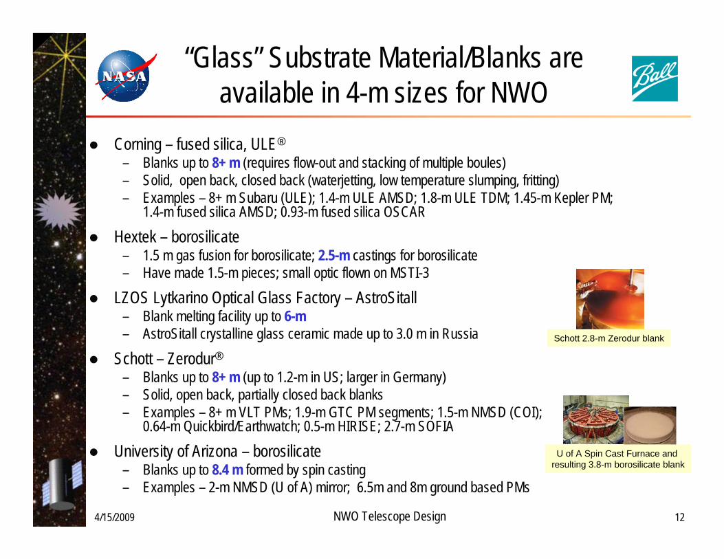
“Glass” Substrate Material/Blanks are available in 4-m sizes for NWO
Corning – fused silica, ULE®
– Blanks up to 8+ m (requires flow-out and stacking of multiple boules)– Solid, open back, closed back (waterjetting, low temperature slumping, fritting)– Examples – 8+ m Subaru (ULE); 1.4-m ULE AMSD; 1.8-m ULE TDM; 1.45-m Kepler PM;
1.4-m fused silica AMSD; 0.93-m fused silica OSCAR
Hextek – borosilicate– 1.5 m gas fusion for borosilicate; 2.5-m castings for borosilicate– Have made 1.5-m pieces; small optic flown on MSTI-3
LZOS Lytkarino Optical Glass Factory – AstroSitall– Blank melting facility up to 6-m– AstroSitall crystalline glass ceramic made up to 3.0 m in Russia
Schott – Zerodur®
– Blanks up to 8+ m (up to 1.2-m in US; larger in Germany)– Solid, open back, partially closed back blanks– Examples – 8+ m VLT PMs; 1.9-m GTC PM segments; 1.5-m NMSD (COI);
0.64-m Quickbird/Earthwatch; 0.5-m HIRISE; 2.7-m SOFIA
University of Arizona – borosilicate– Blanks up to 8.4 m formed by spin casting– Examples – 2-m NMSD (U of A) mirror; 6.5m and 8m ground based PMs
U of A Spin Cast Furnace and resulting 3.8-m borosilicate blank
Schott 2.8-m Zerodur blank
4/15/2009 NWO Telescope Design 13
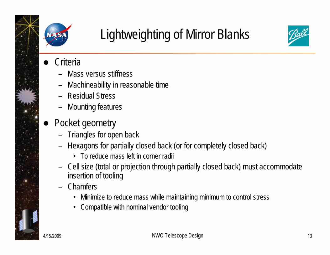
Lightweighting of Mirror Blanks
Criteria– Mass versus stiffness– Machineability in reasonable time– Residual Stress– Mounting features
Pocket geometry– Triangles for open back– Hexagons for partially closed back (or for completely closed back)
• To reduce mass left in corner radii– Cell size (total or projection through partially closed back) must accommodate
insertion of tooling– Chamfers
• Minimize to reduce mass while maintaining minimum to control stress• Compatible with nominal vendor tooling

4/15/2009 NWO Telescope Design 14
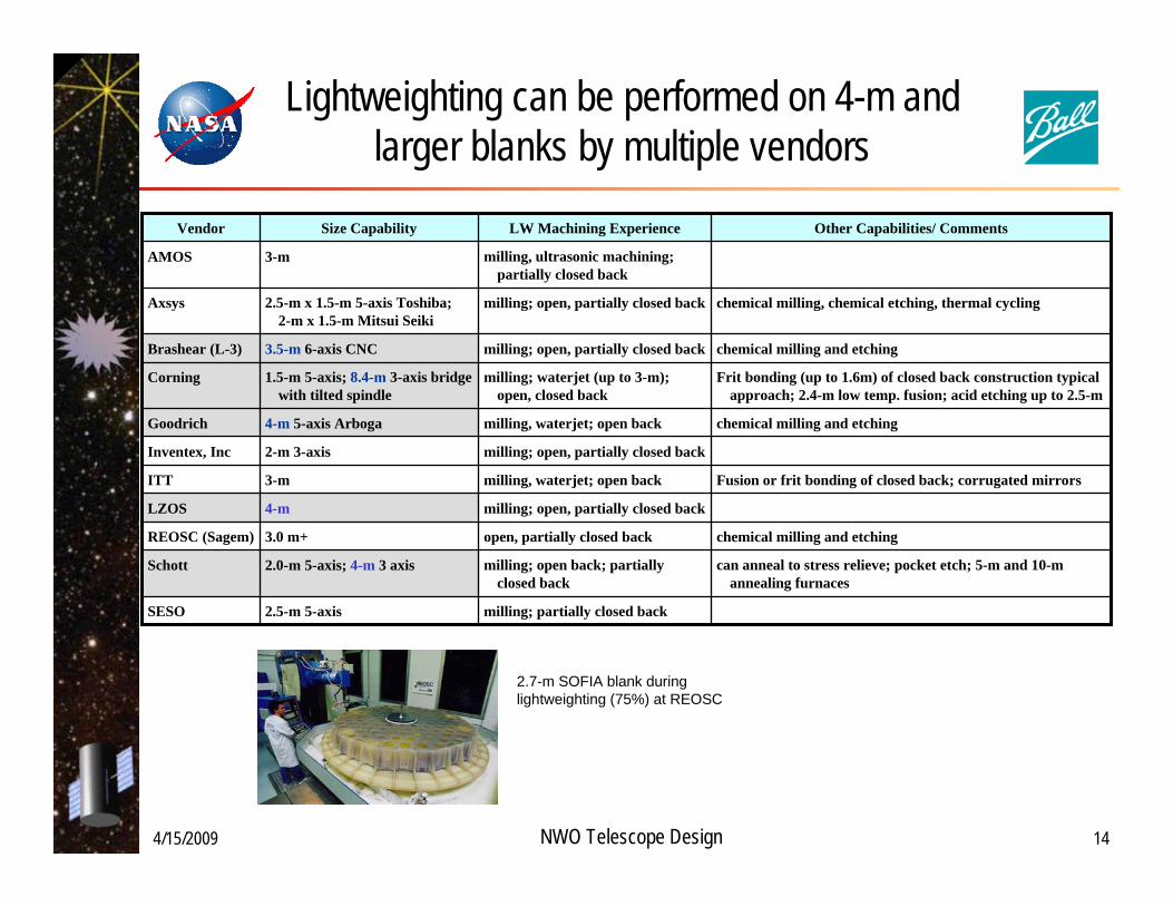
Lightweighting can be performed on 4-m and larger blanks by multiple vendors
milling; partially closed back2.5-m 5-axisSESO
can anneal to stress relieve; pocket etch; 5-m and 10-m annealing furnaces
milling; open back; partially closed back
2.0-m 5-axis; 4-m 3 axisSchott
chemical milling and etchingopen, partially closed back3.0 m+REOSC (Sagem)
milling; open, partially closed back4-mLZOS
Fusion or frit bonding of closed back; corrugated mirrorsmilling, waterjet; open back3-mITT
milling; open, partially closed back2-m 3-axisInventex, Inc
chemical milling and etchingmilling, waterjet; open back4-m 5-axis ArbogaGoodrich
Frit bonding (up to 1.6m) of closed back construction typical approach; 2.4-m low temp. fusion; acid etching up to 2.5-m
milling; waterjet (up to 3-m); open, closed back
1.5-m 5-axis; 8.4-m 3-axis bridge with tilted spindle
Corning
chemical milling and etchingmilling; open, partially closed back3.5-m 6-axis CNCBrashear (L-3)
chemical milling, chemical etching, thermal cyclingmilling; open, partially closed back2.5-m x 1.5-m 5-axis Toshiba; 2-m x 1.5-m Mitsui Seiki
Axsys
milling, ultrasonic machining; partially closed back
3-mAMOS
Other Capabilities/ CommentsLW Machining ExperienceSize CapabilityVendor
2.7-m SOFIA blank during lightweighting (75%) at REOSC
4/15/2009 NWO Telescope Design 15
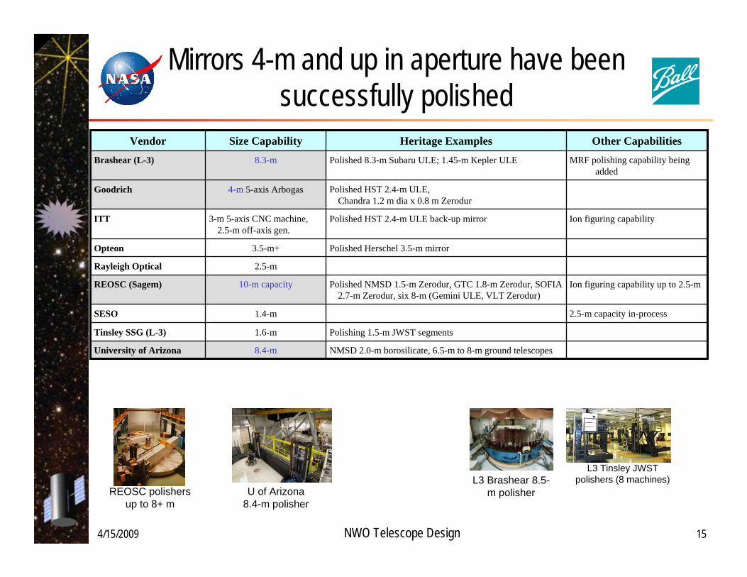
Mirrors 4-m and up in aperture have been successfully polished
NMSD 2.0-m borosilicate, 6.5-m to 8-m ground telescopes8.4-mUniversity of Arizona
Polishing 1.5-m JWST segments1.6-mTinsley SSG (L-3)
2.5-m capacity in-process1.4-mSESO
Ion figuring capability up to 2.5-mPolished NMSD 1.5-m Zerodur, GTC 1.8-m Zerodur, SOFIA 2.7-m Zerodur, six 8-m (Gemini ULE, VLT Zerodur)
10-m capacityREOSC (Sagem)
2.5-mRayleigh Optical
Polished Herschel 3.5-m mirror3.5-m+Opteon
Ion figuring capabilityPolished HST 2.4-m ULE back-up mirror3-m 5-axis CNC machine, 2.5-m off-axis gen.
ITT
Polished HST 2.4-m ULE, Chandra 1.2 m dia x 0.8 m Zerodur
4-m 5-axis ArbogasGoodrich
MRF polishing capability being added
Polished 8.3-m Subaru ULE; 1.45-m Kepler ULE8.3-mBrashear (L-3)
Other CapabilitiesHeritage ExamplesSize CapabilityVendor
REOSC polishers up to 8+ m
L3 Brashear 8.5-m polisherU of Arizona
8.4-m polisher
L3 Tinsley JWST polishers (8 machines)

4/15/2009 NWO Telescope Design 16
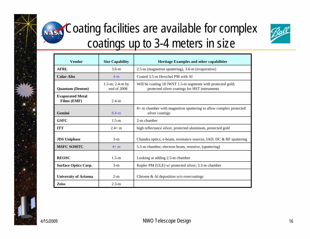
Coating facilities are available for complex coatings up to 3-4 meters in size
2.3-mZeiss
Chrome & Al deposition w/o overcoatings2-mUniversity of Arizona
Kepler PM (ULE) w/ protected silver; 3.3-m chamber3-mSurface Optics Corp.
Looking at adding 2.5-m chamber1.5-mREOSC
5.5-m chamber; electron beam, resistive, (sputtering)4+ mMSFC SOMTC
Chandra optics; e-beam, resistance sources, IAD; DC & RF sputtering3-mJDS Uniphase
high reflectance silver, protected aluminum, protected gold2.4+ mITT
2-m chamber1.5-mGSFC
8+ m chamber with magnetron sputtering to allow complex protected silver coatings8.4-mGemini
2.4-mEvaporated Metal
Films (EMF)
Will be coating 18 JWST 1.5-m segments with protected gold; protected silver coatings for HST instruments
1.5-m; 2.4-m by end of 2008Quantum (Denton)
Coated 3.5-m Herschel PM with Al4-mCalar-Alto
2.5-m (magnetron sputtering), 3.6-m (evaporative)3.6-mAFRL
Heritage Examples and other capabilitiesSize CapabilityVendor
4/15/2009 NWO Telescope Design 17
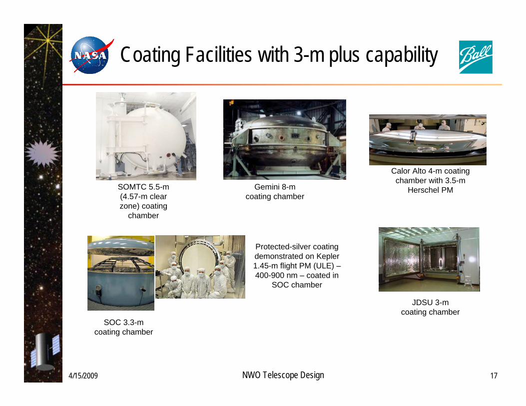
Coating Facilities with 3-m plus capability
Protected-silver coating demonstrated on Kepler1.45-m flight PM (ULE) –400-900 nm – coated in
SOC chamber
SOC 3.3-m coating chamber
Gemini 8-m coating chamber
SOMTC 5.5-m (4.57-m clear zone) coating
chamber
Calor Alto 4-m coating chamber with 3.5-m
Herschel PM
JDSU 3-m coating chamber
4-m NWO Telescope Design
Steve Kendrick
Ball Aerospace & Technologies Corp.

4/15/2009 NWO Telescope Design 2
Overview of Optical Systems Engineering for 4-m aperture NWO telescope
Systems Engineering for large (4-m) aperture telescope– Based on Mission Requirements
Primary Mirror options– Monolithic or Segmented (non-deployed)– Mirror Stiffness Approach – Control Systems – actuators, wavefront sensing
Mirror optical fabrication approaches– Examples of fabrication techniques and potential vendors
Optical coating fabrication candidates
Summary
4/15/2009 NWO Telescope Design 3
NWO Telescope Design Approach is Based on Mission Requirements
Design for large aperture observatory based on science requirements
Derived architecture approach to fulfill science mission
5×5 arcsec1×1 arcsec3×3 arcmin3×3 arcmin
1.5–2.3µm 0.5–1.0µmRequirement
20×20 arcsec10×3 arcsec20×20 arcmin
Fields of viewPlanet detectionPlanet spectroscopyWide field cameraEngineering
1.5–3µmEngineering passband0.1–1.5µmScience passbandGoal
Throughput for UV and exoplanetsAl/MgF2 for PM & SM; Silver for later opticsMirror coatings
RemarksValueCharacteristic
Ambient (~25°C)Fixed with coverMonolithic
Field-angle division; WFcam at TMA, all others at Cassegrain
Obscured
Thermal stability, I&TFits in Atlas-V shroudTopic for future trade
Minimize reflections for UV & exoplanets
No science constraints
Operating temperatureTelescope solar shieldPM architecture
Instrument pickoffs
Telescope architecture
4/15/2009 NWO Telescope Design 4
Future Trades for Primary Mirror
Segmentation and construction options
The necessary trades include:– Mirror stiffness (including materials)– Geometry – Alignment compatibility– Optical performance– Surface control– Manufacturability
Dozens of actuators per segment
100s to 1000s of actuators
Flexible meniscus6-DOF plus curvatureDozens of actuatorsSemi-rigid mirror6-DOF actuatorsKinematic /whiffle-treeRigid mirrorSegmentedMonolithic
4/15/2009 NWO Telescope Design 5
Manufacturing issues affecting cost, complexity, and performance
ULE® and Zerodur®
– Both capable of 4 m monolith– Some differences in manufacturing and lightweighting techniques
Silicon Carbide (SiC)– Lack of heritage for achieving visible-light quality– Domestic facilities up to about 1.8 to 2-m diameter
Optical Coating chamber limitations– Only one domestic chamber identified that can coat larger than 3-m
4/15/2009 NWO Telescope Design 6
Monolithic / Segmented PM Considerations
Science Impact– Scatter, diffraction impact on signal-to-noise of discerning Earth-like planets around exosolar star
Engineering Impact– Scatter and PSF requirements– PM and total telescope system mass– Control System– Error budgets on components, alignment
Manufacturability– Schedule– Cost
Conclusions:Segmented mirror has slightly detrimental science impact relative to monolithic mirrorSensing and control makes segmented PM more complex, and in some ways more risky than a monolithic PMA 4-m monolithic NWO PM is feasible
– can be fabricated from the blank through the coating phases – multiple vendors available for each major fabrication process
Preliminary: monolithic is preferable up to 4-5 m diam
4/15/2009 NWO Telescope Design 7
Science Impact —Stray light from diffraction sidelobes
In the starshade’s shadow, telescope faces <10-8 of target star light– Diffraction sidelobes from obscurations and segmentation are acceptable– On-axis telescope system is desirable to reduce packaging constraints
PM segment scatter from stars outside the telescope FOV
– Nearest mag 15 star (average ~70" away) gives mag 32 in planet pixel at worst possible orientation
Effect of segment misalignments can be large at large angles
4-leg spider gives 4-fold sidelobes with intensity < (3.3×10⁻⁴) (λ/µm)2 (θ/arcsec)-2
3-leg spider gives 6-fold sidelobes with 1/4 the intensity: (8×10⁻⁵) (λ/µm)2 (θ/arcsec)-2
Minimal segmentation with perfect wavefront gives 6-fold sidelobes with peak intensity < (10-3) (λ/µm)2 (θ/arcsec)-2

4/15/2009 NWO Telescope Design 8
Engineering impacts
Mass is driven by required mirror stiffness and gravity sag during tests
– For a given stiffness, segments have lower areal density than monolithic PM
– Must include actuator mass and backplanes appropriate for each mirror type
Stiffness requirements can be very different
– Rigid PM must verify it will be correctly figured passively on orbit
– Semirigid/Flexible/Segmented PM must verify it can be aligned to correct figure on orbit
Mirror polishing specifications –– Segments require tighter rms surface
quality to make room for new WFE budget terms
Mirror prescription– Monolithic mirror would be on-axis– Segments would each be off-axis optics
Control System for segmented PMAssume PM comprises 6 segments
– More segmentation requires more unique prescriptions and higher total costs
At least 7 DOF actuation / segment– RoC actuator for fabrication variability– Hexapod for rigid body alignment– Future trade on higher number of actuators
Requires a wavefront sensor– Baseline would be JWST-like phase
retrieval approach– Visible-UV science wavelengths
• Accuracy and bandwidth likely more demanding than JWST
– Only need diffraction limited wavefront • Less demanding than internal-coronagraph
TPF-C candidates,
4/15/2009 NWO Telescope Design 9
Summary: Monolith/Segments
Mirror costs dependent on mass, WFE, and segmentation parameters
4-m PM currently feasible as either monolithic or segmented
Various cost approaches yield roughly even cost comparison for the two
Recommend reviewing this trade in Phase A– Cost, risk, technology
Kahan & Targove (Proc SPIE 3356, 1998) estimated the breakpoint for a 7-segment vs. monolithic PM ~4m For a 9-segment vs. monolithic PM ~5m
5-m cross-over point
Manufacturability
Substrate Material – Zerodur and ULE blanks can be made at 4m sizeLightweighting – Can be performed on 4-m optics by several vendors Polishing – Can be performed on 4-m optics by several vendorsOptical coating – One vendor identified in continental US for 4-m optics
4/15/2009 NWO Telescope Design 11
Material Candidates
Material propertiesCTE, CTE homogeneity, thermal conductivity, density, stiffness, etc.
– Thermal gradients expected but rotisserie effects can be avoided– Fabrication and test temperatures vs. operating temperature– Rigid vs. Semi-rigid vs. Membrane– Ease of lightweighting, imposing integral mounting interfaces, polishing
NWO material candidates– ULE®, Zerodur® borosilicate, fused silica – all can be used for up to 4-m monoliths
• Zerodur® 4-m blank(s) are sometimes in-stock at Schott Glas– SiC mirrors have been made up to 3.5-m diam (Herschel)
• 30-40µm wavefront quality• Visible quality 4-m monolithic SiC seems like unnecessary technical risk for NWO
– Beryllium – available in hexagons of 1.3-m flat-to-flat or petals up to ~ 1.3-m by 1.7-m • Cryogenic advantages not applicable for NWO
4/15/2009 NWO Telescope Design 12
“Glass” Substrate Material/Blanks are available in 4-m sizes for NWO
Corning – fused silica, ULE®
– Blanks up to 8+ m (requires flow-out and stacking of multiple boules)– Solid, open back, closed back (waterjetting, low temperature slumping, fritting)– Examples – 8+ m Subaru (ULE); 1.4-m ULE AMSD; 1.8-m ULE TDM; 1.45-m Kepler PM;
1.4-m fused silica AMSD; 0.93-m fused silica OSCAR
Hextek – borosilicate– 1.5 m gas fusion for borosilicate; 2.5-m castings for borosilicate– Have made 1.5-m pieces; small optic flown on MSTI-3
LZOS Lytkarino Optical Glass Factory – AstroSitall– Blank melting facility up to 6-m– AstroSitall crystalline glass ceramic made up to 3.0 m in Russia
Schott – Zerodur®
– Blanks up to 8+ m (up to 1.2-m in US; larger in Germany)– Solid, open back, partially closed back blanks– Examples – 8+ m VLT PMs; 1.9-m GTC PM segments; 1.5-m NMSD (COI);
0.64-m Quickbird/Earthwatch; 0.5-m HIRISE; 2.7-m SOFIA
University of Arizona – borosilicate– Blanks up to 8.4 m formed by spin casting– Examples – 2-m NMSD (U of A) mirror; 6.5m and 8m ground based PMs
U of A Spin Cast Furnace and resulting 3.8-m borosilicate blank
Schott 2.8-m Zerodur blank

4/15/2009 NWO Telescope Design 13
Lightweighting of Mirror Blanks
Criteria– Mass versus stiffness– Machineability in reasonable time– Residual Stress– Mounting features
Pocket geometry– Triangles for open back– Hexagons for partially closed back (or for completely closed back)
• To reduce mass left in corner radii– Cell size (total or projection through partially closed back) must accommodate
insertion of tooling– Chamfers
• Minimize to reduce mass while maintaining minimum to control stress• Compatible with nominal vendor tooling
4/15/2009 NWO Telescope Design 14
Lightweighting can be performed on 4-m and larger blanks by multiple vendors
milling; partially closed back2.5-m 5-axisSESO
can anneal to stress relieve; pocket etch; 5-m and 10-m annealing furnaces
milling; open back; partially closed back
2.0-m 5-axis; 4-m 3 axisSchott
chemical milling and etchingopen, partially closed back3.0 m+REOSC (Sagem)
milling; open, partially closed back4-mLZOS
Fusion or frit bonding of closed back; corrugated mirrorsmilling, waterjet; open back3-mITT
milling; open, partially closed back2-m 3-axisInventex, Inc
chemical milling and etchingmilling, waterjet; open back4-m 5-axis ArbogaGoodrich
Frit bonding (up to 1.6m) of closed back construction typical approach; 2.4-m low temp. fusion; acid etching up to 2.5-m
milling; waterjet (up to 3-m); open, closed back
1.5-m 5-axis; 8.4-m 3-axis bridge with tilted spindle
Corning
chemical milling and etchingmilling; open, partially closed back3.5-m 6-axis CNCBrashear (L-3)
chemical milling, chemical etching, thermal cyclingmilling; open, partially closed back2.5-m x 1.5-m 5-axis Toshiba; 2-m x 1.5-m Mitsui Seiki
Axsys
milling, ultrasonic machining; partially closed back
3-mAMOS
Other Capabilities/ CommentsLW Machining ExperienceSize CapabilityVendor
2.7-m SOFIA blank during lightweighting (75%) at REOSC

4/15/2009 NWO Telescope Design 15
Mirrors 4-m and up in aperture have been successfully polished
NMSD 2.0-m borosilicate, 6.5-m to 8-m ground telescopes8.4-mUniversity of Arizona
Polishing 1.5-m JWST segments1.6-mTinsley SSG (L-3)
2.5-m capacity in-process1.4-mSESO
Ion figuring capability up to 2.5-mPolished NMSD 1.5-m Zerodur, GTC 1.8-m Zerodur, SOFIA 2.7-m Zerodur, six 8-m (Gemini ULE, VLT Zerodur)
10-m capacityREOSC (Sagem)
2.5-mRayleigh Optical
Polished Herschel 3.5-m mirror3.5-m+Opteon
Ion figuring capabilityPolished HST 2.4-m ULE back-up mirror3-m 5-axis CNC machine, 2.5-m off-axis gen.
ITT
Polished HST 2.4-m ULE, Chandra 1.2 m dia x 0.8 m Zerodur
4-m 5-axis ArbogasGoodrich
MRF polishing capability being added
Polished 8.3-m Subaru ULE; 1.45-m Kepler ULE8.3-mBrashear (L-3)
Other CapabilitiesHeritage ExamplesSize CapabilityVendor
REOSC polishers up to 8+ m
L3 Brashear 8.5-m polisherU of Arizona
8.4-m polisher
L3 Tinsley JWST polishers (8 machines)
4/15/2009 NWO Telescope Design 16
Coating facilities are available for complex coatings up to 3-4 meters in size
2.3-mZeiss
Chrome & Al deposition w/o overcoatings2-mUniversity of Arizona
Kepler PM (ULE) w/ protected silver; 3.3-m chamber3-mSurface Optics Corp.
Looking at adding 2.5-m chamber1.5-mREOSC
5.5-m chamber; electron beam, resistive, (sputtering)4+ mMSFC SOMTC
Chandra optics; e-beam, resistance sources, IAD; DC & RF sputtering3-mJDS Uniphase
high reflectance silver, protected aluminum, protected gold2.4+ mITT
2-m chamber1.5-mGSFC
8+ m chamber with magnetron sputtering to allow complex protected silver coatings8.4-mGemini
2.4-mEvaporated Metal
Films (EMF)
Will be coating 18 JWST 1.5-m segments with protected gold; protected silver coatings for HST instruments
1.5-m; 2.4-m by end of 2008Quantum (Denton)
Coated 3.5-m Herschel PM with Al4-mCalar-Alto
2.5-m (magnetron sputtering), 3.6-m (evaporative)3.6-mAFRL
Heritage Examples and other capabilitiesSize CapabilityVendor

4/15/2009 NWO Telescope Design 17
Coating Facilities with 3-m plus capability
Protected-silver coating demonstrated on Kepler1.45-m flight PM (ULE) –400-900 nm – coated in
SOC chamber
SOC 3.3-m coating chamber
Gemini 8-m coating chamber
SOMTC 5.5-m (4.57-m clear zone) coating
chamber
Calor Alto 4-m coating chamber with 3.5-m
Herschel PM
JDSU 3-m coating chamber