4 ts ui,k.y. , harvey,w.j. , morton, j.m. and shaw, g. · pdf filea preliminary investigation...
TRANSCRIPT

A Preliminary Investigation of the Vertical Shear Strength of Brick Masonry
1 2 3 Ts ui,K.Y. , Harvey,W. J. , Morton, J.M.
Synopsis
4 and Shaw, G.
·Guidanee on the vertie~l shear strength cf briei<. masonry is not readily available to British enginee:-s The need is disctlS3€.d in som,: àetaiL. Tests for singIe brieks and for short masonry shear pif;rs are p:-cp<Jso:d and SOlile typieal results presented. Ccrrelation bet· ... een erushing strength of brick and mortar, and the. vertical shear strength are discussed.. T1:e effects of stress conce:1trations are investigated. Some preliminary guideline:, Íor design <1ro: presented.
1. Research student. Dundee:. University
2. Leeturer·,. Dundee University
3. Senior Structural Engineer,. Briek Development Association
4. Partner,. W~G". C;urtin and Partners (England)
33

1. INTRODUCTIO:';
Masonry cons~ruct ion, whether of stone or brick, was traditionally massive. The aiI:l of the des ign er, be he craftsman or, lóter, engineer, Has to carry all l oads in compression . Tbis was ensnred by the use cf buttresses and decorative we i gh ts. A deeper under standing of materials and structures has now led to thin ,,'a11 designo
Hhile the structural engineer is not as flucnt in the design of brick masonry as he is Hith concrete or steel he is beginning to understand the place whi ch masonry holds in the operation of engineering materials. This has been mad e possible by the use of much thinner sections, with enormous economic pressure to use half brick (102.5 mm) walls wherever possible. The result has been an increased use of the bending and shear strength of masonry. Over the past t,,'enty years developments in design practise have been restrained by a lack of knoHledge in certain areas, or have gone ahead only \,rhere engineering j udgement indicated a large factor of safety .
In the fourth author's practise, where brick masonry is extensively used, a number of gaps in knowledge have been recognised. The vertical shear strength of brickwork has bee11 of particular concern in a number of their structures. In March 1979 the four authors- joined together to study this aspecto The aim was to produce data which woul-d be directly applicable in designo Some of the locations where vertical shear stress might be critical are therefore discussed here .
1 " . .:. Brick Dia?hragm Walls
The bri ck diaphragm wall resists wind forces in bending. It acts as a series of connec1:cd 1 or box beams, of \l7hich the diaphragms form the ~Tebs. Figure 1 shows th ·~ effect of bending and the assumed distribution of shear stress. Since thi s stress acts in two complementary directions, it . might still be assumed , for a full y bonded wall, that shear on the bedding planes remains criticaI. Architectural considerations, however, may effect the nature of the bond used between the web and the outer leaf. The bending resis.tance of sue h á
Hall may be increased by the application of prestress (fig.2). This will also increase the resistance to shear on the bedding planes, but will increasethe s~ear stress in the vertical direction .
Brick diaphragm walls have been designed in the fourth authors practise for over 14 years . Many use full, alternate course bonding while some have metal ties to provide the shear connection between the diaphragm and the wall panel. In both cases conservative values for strength have been adopted in the absence of test data.
1.3 Cantilevers in Cross Hall Construction
In the de t ail ShO\ffi in figure 3 the traditional design a~proach has been to use a concrete beam to carry the fulL structural load above the cantilever. A better knowledge of shear strength, particularly at the junction between the outer sk in and the cross \17al1 would allow a more economical approach . The concrete may only need to carry the first lift of uncured masonry.
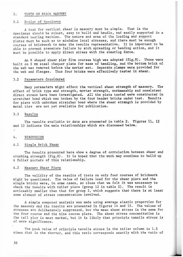
1.4 Vertical Cantilevers for Retaining Structures
The us e of stiff geome tric shapes (fig . 4) for reta~n~ng structures may be mo re confi den t l y approached if reliáble figures for shear resistance were ava i l able. The u se of br í cks f or retaining wal l s, tanks and silos may then be more co~p etiti ve.
34

F 1. 5 The Pn:.diction of Bchz.viour at \·1;:,11 Junc:tions
Hal1 junction:s are subjected to shear stress in a number of ,,,ays. Hind l oading on any structure will cause stresses of a similar form to those descríbed above for diaphragm walls (fig.5). Differential settlement, movement or accidenta1 damag2 ma)' also induce shears which the designer mUBt take into account .
1.6 Requirements
In most of the examples cited above shear develops in combination with tending stresses. For particular applications there will be a need to invest:igate the interaction of these stresses, but, to gíve an earIy indication of avai1able strength to designers, it was decided to study vertical shear as an i solated parameter first.
Sincc: a comprehensive set of tests on alI brick types and strength was beyond the scope of this initial investigation, there was a clear need, either t o seek correlation between various basic material properties and the strength of f inished masonry, or to develop a simple test which would give adequate i nformation on a new brick type. Two groups of tests were therefore performed, one on single bricks and one on masonry piers.
2 . TESTS ON SINGLE BRICKS
2.1 Test Method
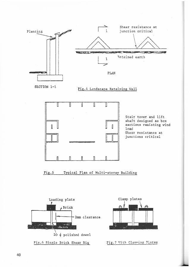
The application of shear stress without significant bending is very difficult. A study of the methods used ~or testing other materiaIs showed that t he test had to be related to the material. In many cases indirect shear was used , for example in the shear prism used for testing adhesives (rer. 2). Since i t seemed probable that the properties of bricks were directional, and since most bricks are relatively long and narrow, the use of a double shear test rig (fig. 6) was proposed.
Preliminary tests using loose support plates led to bending failure, even when the clearance in the shear zone was reduced to 2 mm. It proved in~ossiblc to induce a shear faílure without premature flexural failure if the brick were notc1amped as shown in figure 7. The value of the clamping force had no effect provided it was sufficient to prevent slipping.
AlI the bricks tested were slightly miss shapen, and it was necessary to use some form of bedding. Dental plaster provided a very hard bed which set rapidly. The bed was precast on to the brick on a polished and oiled steel plate , so that a set of ten tests could be completed in one session.
2.2 Results
~~ile work is continuing to test the full range of brick strengths and types, the results available indicate that a simple relationship ma)' exist between vertical shear strength and brick crushing strength (table 1 and fig . S).
35
3 . TESTSON BRICK MASONRY
3 . 1 DE' sign of Specirnens
A test for vertical shear in masonry must be simple. That is the specimens should be robust, easy to build and handle, and easily supported in a standard testing machine. The nature and area of the loading and support plates must be such as to minimise local stresses, and there must be enough courses of brickwork to make the results representative. It is important to be able to prevent premature failure by arch spreading or bendingaction, and it must be possible to apply direct stress with the shearing force.
An H shaped shear pier five courses high was adopted(fig~9). These vere built on 6 mm steel chequer plate for ease of handling. and the bottom brick ·of the web was removed beforethe mortarset. Separate ,clamps wereprovided for the web and flanges. Thus four bricks were effectivelytested in 'shear.
3.2 Parameters Considered
Many parameters might effect the vertical shear strength of masonry. The effect of brick type and strength, mortar strength, workmanship and coexistent direct stress have been investigated. All the piers testedwere constructed in stretcher bond which was broken by the four header bricks under testo '~esults for piers with unbroken stretcher bond where the shear strength is provided by metal ties are not yet available for publication.
3 .3 Results
The results available to date are presented intab~e 2. Figures ll~ 12 and 13 indicate the main relationships which are discussedbelow .•
4. DISCUSSION
4.1 Single Brick Shear
The results presented here show a degree of correlation between shear and crushing strength (fig.S). It is hoped that the work may continue to build up a fuller picture of this relationship.
4.2 Masonry Shear Piers
The va~idity of the results of tests on only four courses of brickwork might be questioned. The value of failure load for the shear piers and the single bricks were, in some cases, so close that we felt it was necessary to check the results with taller piers (group 12 in table 2). The result is noticeably smaller than that for group 2, which suggests that there is at least some element of stress concentration involved.
A simple computer analysis was made using average elastic properties for the masonry and the results are presented in figures 14 and 15. The values of stresses are deliberately suppressed, but the mean shear stress is the same for the four course and the nine course piers. The shear stress concentration in the tall pier is most marked, but it is likely that principIe tensile stress is of more significance .
The peak value of principIe tensile stress in the taller column is 1 . 5 times that in the shorter, and this ratio corresponds exactly with the ratio of
36

roean shear stress at failure. The rever sal of this stres s near the ends of t he shea r plane resu I t from the r es traint provided by the loading and supporting s tee l plates.
The concentr2ticn of stress near the ends of the joint relates cIose ly t o the l ong joint effcc ts recently introduced into British codes of practise for st ruc tural steelwork (ref.3). It results from the incompatible strains in the web. and flanges of the pier \vhen under load (fig . 16). Someelement of redistribution of stress would be expected in a strong brick, weak mortar comb ination, but we do not have sufficient results to confirm this .
It is clear that long joints with shear applied directly as in our tests (s ee fi gure 3 for example) , will need careful analysis. An understanding of the behaviour of diaphragm walls will only be achieved by suitable bending testl?_-, -but the mean va lues of shear . .sJ:rengtil obtained from our tests should be conservative.
The work of Hendry et aI and Curtin et aI on principIe stresses in brickwork roay prove to be applicable to the situation we have studied (ref.l,5). The existing rules for shear in the code of practise BS 5628 effectively limit principIe tensile stress, but without a direct application of stress analysis.
REFERENCES
1 . Curtin, W.G. Brick Diaphragm Walls - development, application, design and future development. The Structural Engineer, Vol 58A, No.2, February 1980.
2. Johnson, R.P. The properties of an epo:h"y mortar and its use for structural joints. The Structural Engineer, Vol 48, No.6, June 1970.
3. British Standards Institution. Draft Eritish Standard for the Structural Use of Steel in Buildings. BS 5950.
4. Samarasinyhe, U. , Page, A.W. and Hendry, A.W. Behaviour of Brick Masonry Shear \valls. The Structural Engineer, Vol 59B, No . 3, September 1981.
5 . Curtin, W.G. and Phipps . The behaviour of post tensioned diaphragm brick walls. To be published.
37

38
-- .... =<:
2 2 I
Crusbing Strength N/mm I Sbear Strengtb l: / rrnn
BRICK TYPE I I STAKDAP~ I STA.'<DARD MEAN I DE VIATION
MEAN I DEVIATION
I _.---....
1 PRESSED "FROGGED 28 3 I 5.5 0.3
2 ) ( 10 bole 51 4 12 . 6 1.4
3 ) E}:TRUDED ( 3 bole 53 4 15.2 1.5 InRE CUT
4 ) ( 3 bole 59 4 13 . 8 1.2
TABLE 1 TES! RESULTS FOR SINGLE BRICKS
r ~ "
C3'J
~ ~ + :x:--
W tIlZ ç... =>
O f:: e3~ Z C-'
[3 ::.: ::': z U ~~ g H
"" P::E-< c.: ~ ;>:4r.n =~'~,
1 4 59
2 1 28
3 3 53
4 3 53
5 3 53
6 4 51
7 4 51
8 4 51
9 4 51
10 3 53
11 3 53 12++ '.
1 28
+ See Tab1 e 1
* 1 í-Jorking Brick1ayer 2 Resear ch Studen t 3 Retired Brick1ayer
++
W
~~ C-'-.D
Lr\ P:: <til E-<~ p::,-" O ~
3
3
3
1
4
1
1
3
3
3
3
3
10 Course high shear pier
ULTIHATE SH~AR 01< SRESS N/mm ~ W til
~ til til O E-<~ ~ ZO
STA."IDA...~D ww UE-< U ç...,..J wv: H "",..J e=~ NEA.T\1 DEVIATION ~ WH ~ ç...r:.. (.:lç...
1 .; O 2.4 0.5
2 .; O 1.5 0 .2
3 .; O 2.5 0.2
3 .; O 3 . 2 0.4
3 .; O 2 . 3 0.3
3 .; O 3 . 2 1.0
3 X O 3.1 0.5
3 .; O 2.9 0.6
3 X O 2 . 2 0.8
2 .; 0.2N/nu·/ 2.2 0 . 3
3 .; 10. 2N ~rrnn 3. 1 0. 7
.; 3 1.0
TA.BLE 2 rEST PJ:SULTS rOR }LI>,.SO:;RY SHEf..R PIERS
k_
-

possible shear failure
Plan on diaphragm Assuroed shear stress distribution
Pl.AN
~ The Diaphragm Hal.l
Capping beam
Latteral resistance increased by prestressing ~ force
tension Iod -':""-H"1
Fig.2 The Post Tensioned DiaDhr~
Shear resistance of bonded junction ~
SECTION
Cl.'osswall criticaI !-,-Outerwall
--------------------------------------~ --Trimmer bearn
--~--------------~------Cantilever
Crosswall
Fig .3 Cantilever in Crosswall Construction
39
40
PLAN
Shear resistance at junction criticaI
~ Retained earth
SECTION l - I Fig.4 Landscape Retaining WaII
u o
DO DO
Stair tm·rer and lift shaft designed as box sections resisting wind Ioad Shear resistance at junctions criticaI
Fig . S TypicaI PIan of Multi-storey BuiIding
Loading pIate CIamp plates
1r-~--4- 2mm clearance
20 ~ polished dowel
FiR.6 Single Brick ShearRig Fig. 7 l\'ith Cla!'1ning Plates

20
N g 15 G·~.Mean of 10
fI ! --:z 'V Hean minus two standard ..c: deviations '"' oc 'V ~ Oi 10 "V ~
'"' tr;
~ ..-ct Oi
..c: _t- -rJ) 5 ~ u ..... ~ ~ .....
..-..... O 20 40 60
Brick Crushing Strength N/mm 2
Fig.8 Shear Strength versus Crushing Strength for Single Bricks
II
1I
·11
r--- r---O· o O O
o o O O
- -
Fig.9 Fig.lO
~ick She~, Piers and Associated ClamDing P1ates
41

4
N e! Mean af ten (with class 3 morta L) §
....... :z;
.Ç
3 '17 Hean minus two standard deviatí on s
O l1ean m~nus two S.D. (elas;; 1 mot' t ar ) ;.J /:)1)
C <li I-< ;.J
Ul 2
H <d <li
.Ç Ul
;>, H 1 I C o '" ctl
:>::
J
O 20 240 Brick Crushing Strength N/mm
60
Fig .ll Mas onry Shear Strength versus Brick Crushing Strcngth
4
t Hean ar 10
N Hean minus t~'lO st,mdard § 3 deviations
....... :z .Ç ! f ... /:)1)
V ~ ).< 2 ;.J cn
I-< V V <d <li ~ cn ;>, 1 I:: o C/l <d
:>:: o
4 3 1
Hortar Grade CRS 5628)
Fig.12 Hasonry Shear Strer.gth Variation \,,lith ~·1ort-1 r GrJ.de
42

r 4
N e e 3 '-. ç::
.c +-l cc ::; <li
'"' 2 +-l <Jl
'"' '" <li .c (J)
;>, 1 '"' ç:: o CJl
'" ::;::
O
• l1ean of 10 "Títh grade 3 mortar li Mean of 10 Hith grade 1 mertar
•
2 4 6 8 10
Brick Shear Strength N/rum 2
- '"' 9 ~I 0012 1:Se til CJl
Pif'1: CJl ClJ
ç:: I '"' ~ I~ ~I
S COl.J 1:se
Piel:
-- Increasíng Shear Stress
Fíg. 14 Variation of Shear Stress in Pier s of Diffarent Hei ght~
11 11
fi
•
-I
1: 14 16
9 -1
8 I
7
6
5
4 CJl ClJ
3 CJl
'"' ::l o u
2 .-" U
' M
1 '"' ~
43

~--8
7
6
.5
Compression Tension
0j';.15 Variation of Minor l'rinc!.e-,ü Stress
in Piers Df Different Heights
44
LOADS
....... ~ .... ~."
... ~ .......... \ .. : ..... . . .
.........
. ~ .... ' ~""'''''' \ .......... ~ H ~~~~~~ __ ~~ ____ ~ ____ ~
.(" ..... \ . .
.- . ..... . ...... .
SUPPO~T