40 jet fourstroke - brunswick marine in...
TRANSCRIPT
eng i
Thank Youfor your purchase of one of the finest outboards available. Youhave made a sound investment in boating pleasure. Youroutboard has been manufactured by Mercury Marine, a worldleader in marine technology and outboard manufacturingsince 1939. These years of experience have been committedto the goal of producing the finest quality products. This led toMercury Marine's reputation for strict quality control,excellence, durability, lasting performance, and being the bestat providing after the sale support.Please read this manual carefully before operating youroutboard. This manual has been prepared to assist you in theoperation, safe use, and care of your outboard.All of us at Mercury Marine took pride in building your outboardand wish you many years of happy and safe boating.Again, thank you for your confidence in Mercury Marine.
EPA Emissions RegulationsOutboards sold by Mercury Marine in the United States arecertified to the United States Environmental ProtectionAgency as conforming to the requirements of the regulationsfor the control of air pollution from new outboard motors. Thiscertification is contingent on certain adjustments being set tofactory standards. For this reason, the factory procedure forservicing the product must be strictly followed and, whereverpracticable, returned to the original intent of the design.Maintenance, replacement, or repair of the emissioncontrol devices and systems may be performed by anymarine engine repair establishment or individual.Engines are labeled with an Emission Control Informationdecal as permanent evidence of EPA certification.
! WARNINGThe engine exhaust from this product contains chemicalsknown to the state of California to cause cancer, birth defectsor other reproductive harm.
© 2
011
Mer
cury
Mar
ine
40 J
et F
ourS
troke
90-8
M00
5487
0 11
1
ii eng
Warranty MessageThe product you have purchased comes with a limited warrantyfrom Mercury Marine, the terms of the warranty are set forth in theWarranty Information section of this manual. The warrantystatement contains a description of what is covered, what is notcovered, the duration of coverage, how to best obtain warrantycoverage, important disclaimers and limitations of damages,and other related information. Please review this importantinformation.The description and specifications contained herein were in effectat the time this manual was approved for printing. Mercury Marine,whose policy is one of continued improvement, reserves the rightto discontinue models at any time, to change specifications,designs, methods, or procedures without notice and withoutincurring obligation.Mercury Marine, Fond du Lac, Wisconsin U.S.A.Litho in U.S.A.© 2011, Mercury MarineMercury, Mercury Marine, MerCruiser, Mercury MerCruiser,Mercury Racing, Mercury Precision Parts, Mercury Propellers,Mariner, Quicksilver, #1 On The Water, Alpha, Bravo, Pro Max,OptiMax, Sport‑Jet, K‑Planes, MerCathode, RideGuide,SmartCraft, Zero Effort, M with Waves logo, Mercury with Waveslogo, and SmartCraft logo are all registered trademarks ofBrunswick Corporation. Mercury Product Protection logo is aregistered service mark of Brunswick Corporation.
Mercury Premier ServiceMercury evaluates the service performance of its dealers andassigns its highest rating of "Mercury Premier" to thosedemonstrating an exceptional commitment to service.Earning a Mercury Premier Service rating means a dealer:• Achieves a high 12 month service CSI (Customer Satisfaction
Index) score for warranty service.• Possesses all necessary service tools, test equipment,
manuals, and parts books.• Employs at least one Certified or Master technician.
eng iii
• Provides timely service for all Mercury Marine customers.• Offers extended service hours and mobile service, when
appropriate.• Uses, displays, and stocks adequate inventory of genuine
Mercury Precision Parts.• Offers a clean, neat shop with well organized tools and service
literature.
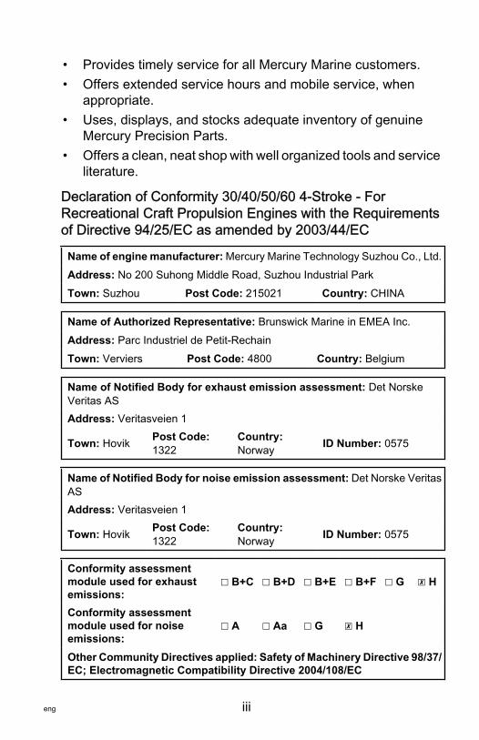
Declaration of Conformity 30/40/50/60 4‑Stroke ‑ ForRecreational Craft Propulsion Engines with the Requirementsof Directive 94/25/EC as amended by 2003/44/EC
Name of engine manufacturer: Mercury Marine Technology Suzhou Co., Ltd.Address: No 200 Suhong Middle Road, Suzhou Industrial ParkTown: Suzhou Post Code: 215021 Country: CHINA
Name of Authorized Representative: Brunswick Marine in EMEA Inc.Address: Parc Industriel de Petit‑RechainTown: Verviers Post Code: 4800 Country: Belgium
Name of Notified Body for exhaust emission assessment: Det NorskeVeritas ASAddress: Veritasveien 1
Town: Hovik Post Code:1322
Country:Norway ID Number: 0575
Name of Notified Body for noise emission assessment: Det Norske VeritasASAddress: Veritasveien 1
Town: Hovik Post Code:1322
Country:Norway ID Number: 0575
Conformity assessmentmodule used for exhaustemissions:
☐ B+C ☐ B+D ☐ B+E ☐ B+F ☐ G ☒ H
Conformity assessmentmodule used for noiseemissions:
☐ A ☐ Aa ☐ G ☒ H
Other Community Directives applied: Safety of Machinery Directive 98/37/EC; Electromagnetic Compatibility Directive 2004/108/EC
iv eng
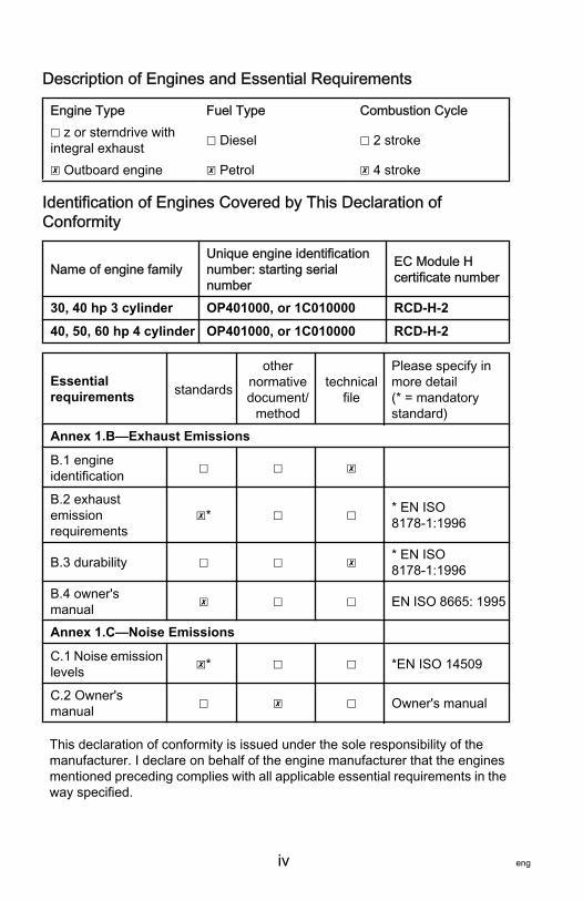
Description of Engines and Essential Requirements
Engine Type Fuel Type Combustion Cycle☐ z or sterndrive withintegral exhaust ☐ Diesel ☐ 2 stroke
☒ Outboard engine ☒ Petrol ☒ 4 stroke
Identification of Engines Covered by This Declaration ofConformity
Name of engine familyUnique engine identificationnumber: starting serialnumber
EC Module Hcertificate number
30, 40 hp 3 cylinder OP401000, or 1C010000 RCD-H-2
40, 50, 60 hp 4 cylinder OP401000, or 1C010000 RCD-H-2
Essentialrequirements standards
othernormativedocument/
method
technicalfile
Please specify inmore detail(* = mandatorystandard)
Annex 1.B—Exhaust Emissions
B.1 engineidentification ☐ ☐ ☒
B.2 exhaustemissionrequirements
☒* ☐ ☐ * EN ISO8178‑1:1996
B.3 durability ☐ ☐ ☒ * EN ISO8178‑1:1996
B.4 owner'smanual ☒ ☐ ☐ EN ISO 8665: 1995
Annex 1.C—Noise Emissions
C.1 Noise emissionlevels ☒* ☐ ☐ *EN ISO 14509
C.2 Owner'smanual ☐ ☒ ☐ Owner's manual
This declaration of conformity is issued under the sole responsibility of themanufacturer. I declare on behalf of the engine manufacturer that the enginesmentioned preceding complies with all applicable essential requirements in theway specified.

eng v
Name / function:Mark D. Schwabero, President, MercuryOutboard
Date and place of issue:July 24, 2008Fond du Lac, Wisconsin, USA

vi eng
eng vii
WARRANTY INFORMATION
Warranty Registration..................................................................1Transfer of Warranty....................................................................1Transfer of Mercury Product Protection (Extended ServiceCoverage) Plan United States and Canada.................................2FourStroke Outboard Limited Warranty.......................................3FourStroke Outboard Limited Warranty.......................................6FourStroke Outboard Limited Warranty.....................................103 Year Limited Warranty Against Corrosion..............................13Warranty Coverage and Exclusions..........................................17U.S. EPA Emissions Limited Warranty......................................19Emission Control System Components.....................................19California Emissions Limited Warranty......................................20California Air Resources Board Explanation of Your CaliforniaEmission Control Warranty Statement.......................................24Emission Certification Star Label...............................................25
viii eng
GENERAL INFORMATION
Boater's Responsibilities............................................................27Before Operating Your Outboard...............................................27Boat Horsepower Capacity........................................................28High‑Speed and High‑Performance Boat Operation.................29Outboard Remote Control Models ............................................29Remote Steering Notice.............................................................30Lanyard Stop Switch..................................................................31Stopping the Boat in an Emergency..........................................33Protecting People In The Water.................................................34Passenger Safety Message ‑ Pontoon Boats and Deck Boats..35Wave and Wake Jumping..........................................................37Safety Instructions for Hand‑Tilled Outboards...........................37Exhaust Emissions....................................................................38Selecting Accessories for Your Outboard..................................41Safe Boating Suggestions.........................................................41Recording Serial Number..........................................................4340 Jet FourStroke Specifications...............................................44Component Identification...........................................................45
TRANSPORTING
Trailering Boat/Outboard...........................................................46Transporting Portable Fuel Tanks.............................................46
FUEL & OIL
Fuel Recommendations.............................................................48Low Permeation Fuel Hose Requirement .................................50Filling Fuel Tank........................................................................50Engine Oil Recommendations...................................................51Checking and Adding Engine Oil...............................................51

eng ix
FEATURES & CONTROLS
Remote Control Features..........................................................53Warning System........................................................................54Power Trim and Tilt....................................................................56Throttle Grip Friction Adjustment ‑ Tiller Handle Models...........60Steering Friction Adjustment ‑ Tiller Handle Models..................60Replaceable Jet Drive Shear Key..............................................61
OPERATION
Pre‑Starting Check List..............................................................62Operating in Freezing Temperatures.........................................62Operating in Saltwater or Polluted Water..................................63Operating in Shallow Water.......................................................63How the Jet Drive Operates.......................................................63Stopping the Boat in an Emergency..........................................65Steering the Boat.......................................................................65Mooring the Boat.......................................................................66Water Intake Blockage...............................................................67Clearing A Lodged Impeller.......................................................67Pre‑Starting Instructions............................................................68Engine Break‑in Procedure........................................................68Starting the Engine ‑ Remote Control Models...........................69Starting the Engine ‑ Tiller Handle Models................................71Gear Shifting .............................................................................74Stopping the Engine .................................................................75Emergency Starting ..................................................................76
x eng
MAINTENANCE
Outboard Care...........................................................................78EPA Emissions Regulations......................................................78Inspection and Maintenance Schedule......................................79Flushing the Cooling System.....................................................81Top Cowl Removal and Installation...........................................83Exterior Care..............................................................................83Battery Inspection .....................................................................84Fuel System...............................................................................84Steering Link Rod Fasteners.....................................................86Corrosion Control Anode...........................................................87Spark Plug Inspection and Replacement...................................88Steering Pull Adjustment........................................................... 89Worn/Dull Impeller.....................................................................89Impeller Clearance Adjustment..................................................90Fuse Replacement.....................................................................90Timing Belt Inspection............................................................... 91Lubrication Points......................................................................92Checking Power Trim Fluid........................................................96Changing Engine Oil .................................................................96Submerged Outboard................................................................98
STORAGE
Storage Preparation...................................................................99Protecting External Outboard Components.............................100Protecting Internal Engine Components..................................100Jet Drive...................................................................................100Positioning Outboard for Storage............................................100Battery Storage........................................................................100

eng xi
TROUBLESHOOTING
Starter Motor Will Not Crank the Engine (Electric Start Models)101Engine Will Not Start................................................................101Engine Runs Erratically...........................................................102Engine Overspeed (Excessive RPM)......................................102Performance Loss....................................................................102Battery Will Not Hold Charge...................................................103
OWNER SERVICE ASSISTANCE
Local Repair Service................................................................104Service Away from Home........................................................104Parts and Accessories Inquiries..............................................104Service Assistance..................................................................104Mercury Marine Service Offices...............................................105
OUTBOARD INSTALLATION
Installation Information.............................................................107Determining the Mounting Height of the Outboard .................109Checking Boat Transom Construction.....................................111Fastening the Outboard...........................................................112Steering Cable ‑ Starboard Side Routed Cable.......................113Steering Link Rod Fasteners...................................................114Steering Cable Seal.................................................................116Fuel Hose Connection ‑ Remote Control Models....................116Electrical Connections and Control Cable Installation.............117Trim‑In Stop Adjustment ‑ Power Trim Models........................123Water Testing..........................................................................123
MAINTENANCE LOG
Maintenance Log.....................................................................125

xii eng
WARRANTY INFORMATION
eng 1
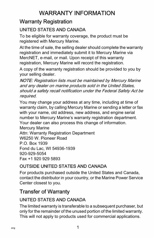
Warranty RegistrationUNITED STATES AND CANADATo be eligible for warranty coverage, the product must beregistered with Mercury Marine.At the time of sale, the selling dealer should complete the warrantyregistration and immediately submit it to Mercury Marine viaMercNET, e‑mail, or mail. Upon receipt of this warrantyregistration, Mercury Marine will record the registration.A copy of the warranty registration should be provided to you byyour selling dealer.NOTE: Registration lists must be maintained by Mercury Marineand any dealer on marine products sold in the United States,should a safety recall notification under the Federal Safety Act berequired.You may change your address at any time, including at time ofwarranty claim, by calling Mercury Marine or sending a letter or faxwith your name, old address, new address, and engine serialnumber to Mercury Marine’s warranty registration department.Your dealer can also process this change of information.Mercury MarineAttn: Warranty Registration DepartmentW6250 W. Pioneer RoadP.O. Box 1939Fond du Lac, WI 54936-1939920-929-5054Fax +1 920 929 5893
OUTSIDE UNITED STATES AND CANADAFor products purchased outside the United States and Canada,contact the distributor in your country, or the Marine Power ServiceCenter closest to you.
Transfer of WarrantyUNITED STATES AND CANADAThe limited warranty is transferable to a subsequent purchaser, butonly for the remainder of the unused portion of the limited warranty.This will not apply to products used for commercial applications.
WARRANTY INFORMATION
2 eng
To transfer the warranty to the subsequent owner, send or fax acopy of the bill of sale or purchase agreement, new owner’s name,address, and engine serial number to Mercury Marine’s warrantyregistration department. In the United States and Canada, mail to:Mercury MarineAttn: Warranty Registration DepartmentW6250 W. Pioneer RoadP.O. Box 1939Fond du Lac, WI 54936-1939920-929-5054Fax +1 920 929 5893Upon processing the transfer of warranty, Mercury Marine willrecord the new owner's information.There is no charge for this service.
OUTSIDE THE UNITED STATES AND CANADAFor products purchased outside the United States and Canada,contact the distributor in your country, or the Marine Power ServiceCenter closest to you.
Transfer of Mercury Product Protection (ExtendedService Coverage) Plan United States and CanadaThe remaining coverage period of the Product Protection Plan istransferable to the subsequent purchaser of the engine within thirty(30) days from the date of sale. Contracts not transferred withinthirty (30) days of the subsequent purchase will no longer be validand the product will no longer be eligible for coverage under theterms of the contract.To transfer the plan to the subsequent owner, contact MercuryProduct Protection or an authorized dealer to receive a Requestfor Transfer form. Submit to Mercury Product Protection a receipt/bill of sale, a completed Request of Transfer form, and a checkpayable to Mercury Marine in the amount of $50.00 (per engine)to cover the transfer fee.Plan coverage is not transferable from one product to anotherproduct or for non‑eligible applications.The Certified Pre‑Owned engine plans are not transferable.
WARRANTY INFORMATION
eng 3
For help or assistance, contact Mercury Product ProtectionDepartment at 1‑888‑427‑5373 from 7:30 a.m. to 4:30 p.m. CST,Monday–Friday or email [email protected].
FourStroke Outboard Limited WarrantyUNITED STATES AND CANADAOutside the United States and Canada ‑ Check with your localdistributor.WHAT IS COVERED: Mercury Marine warrants its new productsto be free of defects in material and workmanship during the perioddescribed below.DURATION OF COVERAGE: This Limited Warranty providescoverage for three (3) years from the date the product is first soldto a recreational use retail purchaser, or the date on which theproduct is first put into service, whichever occurs first. Commercialusers of these products receive warranty coverage of one (1) yearfrom the date of first retail sale, or one (1) year from the date onwhich the product was first put into service, whichever occurs first.Commercial use is defined as any work or employment related useof the product, or any use of the product which generates income,for any part of the warranty period, even if the product is onlyoccasionally used for such purposes. The repair or replacement ofparts, or the performance of service under this warranty, does notextend the life of this warranty beyond its original expiration date.Unexpired warranty coverage can be transferred from onerecreational use customer to a subsequent recreational usecustomer upon proper reregistration of the product. Unexpiredwarranty coverage cannot be transferred either to or from acommercial use customer. Warranty coverage may be terminatedfor used repossessed product; or product purchased at auction,from a salvage yard, or from an insurance company.
WARRANTY INFORMATION
4 eng
CONDITIONS THAT MUST BE MET IN ORDER TO OBTAINWARRANTY COVERAGE: Warranty coverage is available only toretail customers that purchase from a Dealer authorized byMercury Marine to distribute the product in the country in which thesale occurred, and then only after the Mercury Marine specifiedpredelivery inspection process is completed and documented.Warranty coverage becomes available upon proper registration ofthe product by the authorized dealer. Inaccurate warrantyregistration information regarding recreational use, or subsequentchange of use from recreational to commercial (unless properlyreregistered) may void the warranty at the sole discretion ofMercury Marine. Routine maintenance outlined in the Operationand Maintenance Manual must be timely performed in order tomaintain warranty coverage. Mercury Marine reserves the right tomake warranty coverage contingent upon proof of propermaintenance.WHAT MERCURY WILL DO: Mercury's sole and exclusiveobligation under this warranty is limited to, at our option, repairinga defective part, replacing such part or parts with new or MercuryMarine certified remanufactured parts, or refunding the purchaseprice of the Mercury product. Mercury reserves the right to improveor modify products from time to time without assuming anobligation to modify products previously manufactured.HOW TO OBTAIN WARRANTY COVERAGE: The customer mustprovide Mercury with a reasonable opportunity to repair, andreasonable access to the product for warranty service. Warrantyclaims shall be made by delivering the product for inspection to aMercury dealer authorized to service the product. If purchasercannot deliver the product to such a dealer, written notice must begiven to Mercury. We will then arrange for the inspection and anycovered repair. Purchaser, in that case, shall pay for all relatedtransportation charges and/or travel time. If the service provided isnot covered by this warranty, purchaser shall pay for all relatedlabor and material, and any other expenses associated with thatservice. Purchaser shall not, unless requested by Mercury, shipthe product or parts of the product directly to Mercury. Proof ofregistered ownership must be presented to the dealer at the timewarranty service is requested in order to obtain coverage.
WARRANTY INFORMATION
eng 5
WHAT IS NOT COVERED: This limited warranty does not coverroutine maintenance items, tune‑ups, adjustments, normal wearand tear, damage caused by abuse, abnormal use, use of apropeller or gear ratio that does not allow the engine to run in itsrecommended wide‑open throttle RPM range (see the Operationand Maintenance Manual), operation of the product in a mannerinconsistent with the recommended operation/duty cycle sectionof the Operation and Maintenance Manual, neglect, accident,submersion, improper installation (proper installationspecifications and techniques are set forth in the installationinstructions for the product), improper service, use of an accessoryor part not manufactured or sold by us, jet pump impellers andliners, operation with fuels, oils, or lubricants which are not suitablefor use with the product (see the Operation and MaintenanceManual), alteration or removal of parts, water entering the enginethrough the fuel intake, air intake or exhaust system, or damage tothe product from insufficient cooling water caused by blockage ofthe cooling system by a foreign body, running the engine out ofwater, mounting the engine too high on the transom, or running theboat with the engine trimmed out too far. Use of the product forracing or other competitive activity, or operating with a racing typelower unit, at any point, even by a prior owner of the product, voidsthe warranty.Expenses related to haul‑out, launch, towing, storage, telephone,rental, inconvenience, slip fees, insurance coverage, loanpayments, loss of time, loss of income, or any other type ofincidental or consequential damages are not covered by thiswarranty. Also, expenses associated with the removal and/orreplacement of boat partitions or material caused by boat designfor access to the product are not covered by this warranty.No individual or entity, including Mercury Marine authorizeddealers, has been given authority by Mercury Marine to make anyaffirmation, representation, or warranty regarding the product,other than those contained in this limited warranty, and if made,shall not be enforceable against Mercury Marine.
WARRANTY INFORMATION
6 eng
For additional information regarding events and circumstancescovered by this warranty, and those that are not, see the WarrantyCoverage section of the Operation and Maintenance Manual,incorporated by reference into this warranty.
DISCLAIMERS AND LIMITATIONS:THE IMPLIED WARRANTIES OF MERCHANTABILITY AND FITNESS FOR APARTICULAR PURPOSE ARE EXPRESSLY DISCLAIMED. TO THE EXTENTTHAT THEY CANNOT BE DISCLAIMED, THE IMPLIED WARRANTIES ARELIMITED IN DURATION TO THE LIFE OF THE EXPRESS WARRANTY.INCIDENTAL AND CONSEQUENTIAL DAMAGES ARE EXCLUDED FROMCOVERAGE UNDER THIS WARRANTY. SOME STATES/COUNTRIES DONOT ALLOW FOR THE DISCLAIMERS, LIMITATIONS AND EXCLUSIONSIDENTIFIED ABOVE, AS A RESULT, THEY MAY NOT APPLY TO YOU. THISWARRANTY GIVES YOU SPECIFIC LEGAL RIGHTS, AND YOU MAY ALSOHAVE OTHER LEGAL RIGHTS WHICH VARY FROM STATE TO STATE ANDCOUNTRY TO COUNTRY.
FourStroke Outboard Limited WarrantyEUROPE AND CONFEDERATION OF INDEPENDENTSTATESOutside Europe and Confederation of Independent States ‑ checkwith local distributor.WHAT IS COVERED: Mercury Marine warrants its new productsto be free of defects in material and workmanship during the perioddescribed below.
WARRANTY INFORMATION
eng 7
DURATION OF COVERAGE: This Limited Warranty providescoverage for two (2) years from the date the product is first sold toa recreational use retail purchaser, or the date on which theproduct is first put into service, whichever occurs first. Commercialusers of these products receive warranty coverage of one (1) yearfrom the date of first retail sale, or one (1) year from the date inwhich the product was first put into service, whichever occurs first.Commercial use is defined as any work or employment related useof the product, or any use of the product which generates income,for any part of the warranty period, even if the product is onlyoccasionally used for such purposes. The repair or replacement ofparts, or the performance of service under this warranty, does notextend the life of this warranty beyond its original expiration date.Unexpired warranty coverage can be transferred from onerecreational use customer to a subsequent recreational usecustomer upon proper reregistration of the product. Unexpiredwarranty coverage cannot be transferred either to or from acommercial use customer. Warranty coverage may be terminatedfor used or repossessed product; or product purchased at auction,from a salvage yard, or from an insurance company.CONDITIONS THAT MUST BE MET IN ORDER TO OBTAINWARRANTY COVERAGE: Warranty coverage is available only toretail customers that purchase from a Dealer authorized byMercury Marine to distribute the product in the country in which thesale occurred, and then only after the Mercury Marine specifiedpredelivery inspection process is completed and documented.Warranty coverage becomes available upon proper registration ofthe product by the authorized dealer. Routine maintenanceoutlined in the Operation and Maintenance Manual must be timelyperformed in order to maintain warranty coverage. Mercury Marinereserves the right to make future warranty coverage contingent onproof of proper maintenance.
WARRANTY INFORMATION
8 eng
WHAT MERCURY WILL DO: Mercury’s sole and exclusiveobligation under this warranty is limited to, at our option, repairinga defective part, replacing such part or parts with new or MercuryMarine certified remanufactured parts, or refunding the purchaseprice of the Mercury product. Mercury reserves the right to improveor modify products from time to time without assuming anobligation to modify products previously manufactured.HOW TO OBTAIN WARRANTY COVERAGE: The customermust provide Mercury with a reasonable opportunity to repair, andreasonable access to the product for warranty service. Warrantyclaims shall be made by delivering the product for inspection to aMercury dealer authorized to service the product. If purchasercannot deliver the product to such a dealer, written notice must begiven to Mercury. We will then arrange for the inspection and anycovered repair. Purchaser in that case shall pay for all relatedtransportation charges and/or travel time. If the service provided isnot covered by this warranty, purchaser shall pay for all relatedlabor and material, and any other expenses associated with thatservice. Purchaser shall not, unless requested by Mercury, shipthe product or parts of the product directly to Mercury. Proof ofregistered ownership must be presented to the dealer at the timewarranty service is requested in order to obtain coverage.
WARRANTY INFORMATION
eng 9
WHAT IS NOT COVERED: This limited warranty does not coverroutine maintenance items, tune‑ups, adjustments, normal wearand tear, damage caused by abuse, abnormal use, use of apropeller or gear ratio that does not allow the engine to run in itsrecommended wide‑open throttle RPM range (see the Operationand Maintenance Manual), operation of the product in a mannerinconsistent with the recommended operation/duty cycle sectionof the Operation and Maintenance Manual, neglect, accident,submersion, improper installation (proper installationspecifications and techniques are set forth in the installationinstructions for the product), improper service, use of an accessoryor part not manufactured or sold by us, jet pump impellers andliners, operation with fuels, oils or lubricants which are not suitablefor use with the product (see the Operation and MaintenanceManual), alteration or removal of parts, or water entering theengine through the fuel intake, air intake or exhaust system, ordamage to the product from insufficient cooling water caused byblockage of the cooling system by a foreign body, running theengine out of water, mounting the engine too high on the transom,or running the boat with the engine trimmed out too far. Use of theproduct for racing or other competitive activity, or operating with aracing type lower unit, at any point, even by a prior owner of theproduct, voids the warranty.Expenses related to haul out, launch, towing, storage, telephone,rental, inconvenience, slip fees, insurance coverage, loanpayments, loss of time, loss of income, or any other type ofincidental or consequential damages are not covered by thiswarranty. Also, expenses associated with the removal and/orreplacement of boat partitions or material caused by boat designfor access to the product are not covered by this warranty.No individual or entity, including Mercury Marine authorizeddealers, has been given authority by Mercury Marine to make anyaffirmation, representation or warranty regarding the product,other than those contained in this limited warranty, and if made,shall not be enforceable against Mercury Marine.
WARRANTY INFORMATION
10 eng
For additional information regarding events and circumstancescovered by this warranty, and those that are not, see the WarrantyCoverage section of the Operation and Maintenance Manual,incorporated by reference into this warranty.
DISCLAIMERS AND LIMITATIONS:THE IMPLIED WARRANTIES OF MERCHANTABILITY AND FITNESS FOR APARTICULAR PURPOSE ARE EXPRESSLY DISCLAIMED. TO THE EXTENTTHAT THEY CANNOT BE DISCLAIMED, THE IMPLIED WARRANTIES ARELIMITED IN DURATION TO THE LIFE OF THE EXPRESS WARRANTY.INCIDENTAL AND CONSEQUENTIAL DAMAGES ARE EXCLUDED FROMCOVERAGE UNDER THIS WARRANTY. SOME STATES/COUNTRIES DONOT ALLOW FOR THE DISCLAIMERS, LIMITATIONS AND EXCLUSIONSIDENTIFIED ABOVE, AS A RESULT, THEY MAY NOT APPLY TO YOU. THISWARRANTY GIVES YOU SPECIFIC LEGAL RIGHTS, AND YOU MAY ALSOHAVE OTHER LEGAL RIGHTS WHICH VARY FROM STATE TO STATE ANDCOUNTRY TO COUNTRY.
FourStroke Outboard Limited WarrantyMIDDLE-EAST AND AFRICAWHAT IS COVERED: Mercury Marine warrants its new Outboardand Jet Products to be free of defects in material and workmanshipduring the period described below.

WARRANTY INFORMATION
eng 11
DURATION OF COVERAGE: This Limited Warranty providescoverage for one (1) year from the date the product is first sold toa recreational use retail purchaser, or the date on which theproduct is first put into service, whichever occurs first. Commercialusers of these products receive warranty coverage of one (1) yearsfrom the date of first retail sale, or one (1) year from the date onwhich the product was first put into service, whichever occurs first.Commercial use is defined as any work or employment related useof the product, or any use of the product which generates income,for any part of the warranty period, even if the product is onlyoccasionally used for such purposes. The repair or replacement ofparts, or the performance of service under this warranty, does notextend the life of this warranty beyond its original expiration date.Unexpired warranty coverage can be transferred from onerecreational use customer to a subsequent recreational usecustomer upon proper reregistration of the product. Unexpiredwarranty coverage cannot be transferred either to or from acommercial use customer.CONDITIONS THAT MUST BE MET IN ORDER TO OBTAINWARRANTY COVERAGE: Warranty coverage is available only toretail customers that purchase from a Dealer authorized byMercury Marine to distribute the product in the country in which thesale occurred, and then only after the Mercury Marine specifiedpredelivery inspection process is completed and documented.Warranty coverage becomes available upon proper registration ofthe product by the authorized dealer. Routine maintenanceoutlined in the Operation and Maintenance Manual must be timelyperformed in order to maintain warranty coverage. Mercury Marinereserves the right to make warranty coverage contingent on proofof proper maintenance.WHAT MERCURY WILL DO: Mercury’s sole and exclusiveobligation under this warranty is limited to, at our option, repairinga defective part, replacing such part or parts with new or MercuryMarine certified remanufactured parts, or refunding the purchaseprice of the Mercury product. Mercury reserves the right to improveor modify products from time to time without assuming anobligation to modify products previously manufactured.

WARRANTY INFORMATION
12 eng
HOW TO OBTAIN WARRANTY COVERAGE: The customermust provide Mercury with a reasonable opportunity to repair, andreasonable access to the product for warranty service. Warrantyclaims shall be made by delivering the product for inspection to aMercury dealer authorized to service the product. If purchasercannot deliver the product to such a dealer, written notice must begiven to Mercury. We will then arrange for the inspection and anycovered repair. Purchaser in that case shall pay for all relatedtransportation charges and/or travel time. If the service provided isnot covered by this warranty, purchaser shall pay for all relatedlabor and material, and any other expenses associated with thatservice. Purchaser shall not, unless requested by Mercury, shipthe product or parts of the product directly to Mercury. Proof ofregistered ownership must be presented to the dealer at the timewarranty service is requested in order to obtain coverage.WHAT IS NOT COVERED: This limited warranty does not coverroutine maintenance items, tune‑ups, adjustments, normal wearand tear, damage caused by abuse, abnormal use, use of apropeller or gear ratio that does not allow the engine to run in itsrecommended wide‑open throttle RPM range (see the Operationand Maintenance Manual), operation of the product in a mannerinconsistent with the recommended operation/duty cycle sectionof the Operation and Maintenance Manual, neglect, accident,submersion, improper installation (proper installationspecifications and techniques are set forth in the installationinstructions for the product), improper service, use of an accessoryor part not manufactured or sold by us, jet pump impellers andliners, operation with fuels, oils or lubricants which are not suitablefor use with the product (see the Operation and MaintenanceManual), alteration or removal of parts, or water entering theengine through the fuel intake, air intake or exhaust system, ordamage to the product from insufficient cooling water caused byblockage of the cooling system by foreign body, running the engineout of water, mounting the engine too high on the transom, orrunning the boat with the engine trimmed out too far.Use of the product for racing or other competitive activity, oroperating with a racing type lower unit, at any point, even by a priorowner of the product, voids the warranty.
WARRANTY INFORMATION
eng 13
Expenses related to haul out, launch, towing, storage, telephone,rental, inconvenience, slip fees, insurance coverage, loanpayments, loss of time, loss of income, or any other type ofincidental or consequential damages are not covered by thiswarranty. Also, expenses associated with the removal and/orreplacement of boat partitions or material caused by boat designfor access to the product are not covered by this warranty.No individual or entity, including Mercury Marine authorizeddealers, has been given authority by Mercury Marine to make anyaffirmation, representation or warranty regarding the product,other than those contained in this limited warranty, and if made,shall not be enforceable against Mercury Marine.For additional information regarding events and circumstancescovered by this warranty, and those that are not, see the WarrantyCoverage section of the Operation and Maintenance Manual,incorporated by reference into this warranty.
DISCLAIMERS AND LIMITATIONS:THE IMPLIED WARRANTIES OF MERCHANTABILITY AND FITNESS FOR APARTICULAR PURPOSE ARE EXPRESSLY DISCLAIMED. TO THE EXTENTTHAT THEY CANNOT BE DISCLAIMED, THE IMPLIED WARRANTIES ARELIMITED IN DURATION TO THE LIFE OF THE EXPRESS WARRANTY.INCIDENTAL AND CONSEQUENTIAL DAMAGES ARE EXCLUDED FROMCOVERAGE UNDER THIS WARRANTY. SOME STATES/COUNTRIES DONOT ALLOW FOR THE DISCLAIMERS, LIMITATIONS AND EXCLUSIONSIDENTIFIED ABOVE, AS A RESULT, THEY MAY NOT APPLY TO YOU. THISWARRANTY GIVES YOU SPECIFIC LEGAL RIGHTS, AND YOU MAY ALSOHAVE OTHER LEGAL RIGHTS WHICH VARY FROM STATE TO STATE ANDCOUNTRY TO COUNTRY.
3 Year Limited Warranty Against CorrosionWHAT IS COVERED: Mercury Marine warrants that each newMercury, Mariner, Mercury Racing, Sport Jet, M2 Jet Drive, Trackerby Mercury Marine Outboard, Mercury MerCruiser Inboard orSterndrive Engine (Product) will not be rendered inoperative as adirect result of corrosion for the period of time described below.
WARRANTY INFORMATION
14 eng
DURATION OF COVERAGE: This limited corrosion warrantyprovides coverage for three (3) years from either the date theproduct is first sold, or the date on which the product is first put intoservice, whichever occurs first. The repair or replacement of parts,or the performance of service under this warranty, does not extendthe life of this warranty beyond its original expiration date.Unexpired warranty coverage can be transferred to subsequent(noncommercial use) purchaser upon proper reregistration of theproduct.CONDITIONS THAT MUST BE MET IN ORDER TO OBTAINWARRANTY COVERAGE: Warranty coverage is available only toretail customers that purchase from a Dealer authorized byMercury Marine to distribute the product in the country in which thesale occurred, and then only after the Mercury Marine specifiedpredelivery inspection process is completed and documented.Warranty coverage becomes available upon proper registration ofthe product by the authorized dealer. Corrosion prevention devicesspecified in the Operation and Maintenance Manual must be in useon the boat, and routine maintenance outlined in the Operation andMaintenance Manual must be timely performed (including, withoutlimitation, the replacement of sacrificial anodes, use of specifiedlubricants, and touch‑up of nicks and scratches) in order tomaintain warranty coverage. Mercury Marine reserves the right tomake warranty coverage contingent upon proof of propermaintenance.WHAT MERCURY WILL DO: Mercury's sole and exclusiveobligation under this warranty is limited to, at our option, repairinga corroded part, replacing such part or parts with new or MercuryMarine certified remanufactured parts, or refunding the purchaseprice of the Mercury product. Mercury reserves the right to improveor modify products from time to time without assuming anobligation to modify products previously manufactured.
WARRANTY INFORMATION
eng 15
HOW TO OBTAIN WARRANTY COVERAGE: The customer mustprovide Mercury with a reasonable opportunity to repair, andreasonable access to the product for warranty service. Warrantyclaims shall be made by delivering the product for inspection to aMercury dealer authorized to service the product. If purchasercannot deliver the product to such a dealer, written notice must begiven to Mercury. We will then arrange for the inspection and anycovered repair. Purchaser, in that case, shall pay for all relatedtransportation charges and/or travel time. If the service provided isnot covered by this warranty, purchaser shall pay for all relatedlabor and material, and any other expenses associated with thatservice. Purchaser shall not, unless requested by Mercury, shipthe product or parts of the product directly to Mercury. Proof ofregistered ownership must be presented to the dealer at the timewarranty service is requested in order to obtain coverage.WHAT IS NOT COVERED: This limited warranty does not coverelectrical system corrosion; corrosion resulting from damage,corrosion which causes purely cosmetic damage, abuse, orimproper service; corrosion to accessories, instruments, steeringsystems; corrosion to factory installed jet drive unit; damage dueto marine growth; product sold with less than a one year limitedProduct warranty; replacement parts (parts purchased bycustomer); products used in a commercial application.Commercial use is defined as any work or employment related useof the product, or any use of the product which generates income,for any part of the warranty period, even if the product is onlyoccasionally used for such purposes.
WARRANTY INFORMATION
16 eng
Corrosion damage caused by stray electrical currents (onshorepower connections, nearby boats, submerged metal) is notcovered by this corrosion warranty and should be protectedagainst by the use of a corrosion protection system, such as theMercury Precision Parts or Quicksilver MerCathode system and/or Galvanic Isolator. Corrosion damage caused by improperapplication of copper base antifouling paints is also not covered bythis limited warranty. If antifouling protection is required,Tri‑Butyl‑Tin‑Adipate (TBTA) base antifouling paints arerecommended on Outboard and MerCruiser boating applications.In areas where TBTA base paints are prohibited by law, copperbase paints can be used on the hull and transom. Do not applypaint to the outboard or MerCruiser product. In addition, care mustbe taken to avoid an electrical interconnection between thewarranted product and the paint. For MerCruiser product, anunpainted gap of at least 38 mm (1.5 in.) should be left around thetransom assembly. Refer to the Operation and MaintenanceManual for additional details.For additional information regarding events and circumstancescovered by this warranty, and those that are not, see the WarrantyCoverage section of the Operation and Maintenance Manual,incorporated by reference into this warranty.
DISCLAIMERS AND LIMITATIONS:THE IMPLIED WARRANTIES OF MERCHANTABILITY AND FITNESS FOR APARTICULAR PURPOSE ARE EXPRESSLY DISCLAIMED. TO THE EXTENTTHAT THEY CANNOT BE DISCLAIMED, THE IMPLIED WARRANTIES ARELIMITED IN DURATION TO THE LIFE OF THE EXPRESS WARRANTY.INCIDENTAL AND CONSEQUENTIAL DAMAGES ARE EXCLUDED FROMCOVERAGE UNDER THIS WARRANTY. SOME STATES/COUNTRIES DONOT ALLOW FOR THE DISCLAIMERS, LIMITATIONS AND EXCLUSIONSIDENTIFIED ABOVE, AS A RESULT, THEY MAY NOT APPLY TO YOU. THISWARRANTY GIVES YOU SPECIFIC LEGAL RIGHTS, AND YOU MAY ALSOHAVE OTHER LEGAL RIGHTS WHICH VARY FROM STATE TO STATE ANDCOUNTRY TO COUNTRY.
WARRANTY INFORMATION
eng 17
Warranty Coverage and ExclusionsThe purpose of this section is to help eliminate some of the morecommon misunderstandings regarding warranty coverage. Thefollowing information explains some of the types of services thatare not covered by warranty. The provisions set forth followinghave been incorporated by reference into the Three Year LimitedWarranty Against Corrosion Failure, the International LimitedOutboard Warranty, and the United States and Canada LimitedOutboard Warranty.Keep in mind that warranty covers repairs that are needed withinthe warranty period because of defects in material andworkmanship. Installation errors, accidents, normal wear, and avariety of other causes that affect the product are not covered.Warranty is limited to defects in material or workmanship, but onlywhen the consumer sale is made in the country to whichdistribution is authorized by us.Should you have any questions concerning warranty coverage,contact your authorized dealer. They will be pleased to answer anyquestions that you may have.
GENERAL EXCLUSIONS FROM WARRANTY1. Minor adjustments and tune‑ups, including checking,
cleaning, or adjusting spark plugs, ignition components,carburetor settings, filters, belts, controls, and checkinglubrication made in connection with normal services.
2. Factory installed jet drive units ‑ Specific parts excluded fromthe warranty are: the jet drive impeller and jet drive linerdamaged by impact or wear, and water damaged driveshaftbearings as a result of improper maintenance.
3. Damage caused by neglect, lack of maintenance, accident,abnormal operation, or improper installation or service.
4. Haul‑out, launch, towing charges, removal and/orreplacement of boat partitions or material because of boatdesign for necessary access to the product, all relatedtransportation charges and/or travel time, etc. Reasonableaccess must be provided to the product for warranty service.Customer must deliver product to an authorized dealer.

WARRANTY INFORMATION
18 eng
5. Additional service work requested by customer other than thatnecessary to satisfy the warranty obligation.
6. Labor performed by other than an authorized dealer may becovered only under the following circumstances: whenperformed on emergency basis (providing there are noauthorized dealers in the area who can perform the workrequired or have no facilities to haul‑out, etc., and prior factoryapproval has been given to have the work performed at thisfacility).
7. All incidental and/or consequential damages (storagecharges, telephone or rental charges of any type,inconvenience or loss of time or income) are the owner'sresponsibility.
8. Use of other than Mercury Precision or Quicksilver parts whenmaking warranty repairs.
9. Oils, lubricants, or fluids changed as a matter of normalmaintenance is customer's responsibility unless loss orcontamination of same is caused by product failure that wouldbe eligible for warranty consideration.
10.Participating in or preparing for racing or other competitiveactivity or operating with a racing type lower unit.
11.Engine noise does not necessarily indicate a serious engineproblem. If diagnosis indicates a serious internal enginecondition which could result in a failure, condition responsiblefor noise should be corrected under the warranty.
12.Lower unit and/or propeller damage caused by striking asubmerged object is considered a marine hazard.
13.Water entering engine through the fuel intake, air intake, orexhaust system or submersion.
14.Failure of any parts caused by lack of cooling water, whichresults from starting motor out of water, foreign materialblocking inlet holes, motor being mounted too high, or trimmedtoo far out.
15.Use of fuels and lubricants which are not suitable for use withor on the product. Refer to the Maintenance section.
WARRANTY INFORMATION
eng 19
16.Our limited warranty does not apply to any damage to ourproducts caused by the installation or use of parts andaccessories which are not manufactured or sold by us.Failures which are not related to the use of those parts oraccessories are covered under warranty if they otherwisemeet the terms of the limited warranty for that product.
U.S. EPA Emissions Limited WarrantyConsistent with the obligations created by 40 CFR Part 1045,Subpart B, Mercury Marine provides a five year or 175 hours ofengine use, whichever occurs first, to the retail customer, that theengine is designed, built, and equipped so as to conform at thetime of sale with applicable regulations under section 213 of theClean Air Act, and that the engine is free from defects in materialsand workmanship which cause the engine to fail to conform withapplicable regulations. This emission‑related warranty covers allthe components listed in the Emission Control SystemComponents.
Emission Control System ComponentsThe EPA and Califormia emission‑related warranty covers all thefollowing list of components:
COMPONENTS OF THE EMISSIONS CONTROL SYSTEM:1. Fuel metering system
a. Carburetor and internal parts (and/or pressure regulator orfuel injection system)
b. Cold start enrichment systemc. Intake valves
2. Air induction systema. Intake manifoldb. Turbocharger or supercharger systems (where applicable)
3. Ignition systema. Spark plugsb. Magneto or electronic ignition systemc. Spark advance/retard systemd. Ignition coil and/or control module
WARRANTY INFORMATION
20 eng
e. Ignition wires4. Lubrication system (4‑Stroke engines excluded)
a. Oil pump and internal partsb. Oil injectorsc. Oil meter
5. Exhaust systema. Exhaust manifoldb. Exhaust valves
6. Miscellaneous items used in above systemsa. Hoses, clamps, fittings, tubing, sealing gaskets or devices,
and mounting hardwareb. Pulleys, belts, and idlersc. Vacuum, temperature, check and time sensitive valves and
switchesd. Electronic controls
The emission‑related warranty does not cover components whosefailure would not increase an engine's emissions on any regulatedpollutant.
California Emissions Limited WarrantyThe California Air Resources Board has promulgated air emissionregulations for outboard engines. The regulations apply to alloutboard engines sold to retail consumers in California, and whichwere manufactured for the 2001 model year and later. MercuryMarine, in compliance with those regulations, provides this limitedwarranty for the emission control systems (see the componentslisted in the Emission Control System Components), and furtherwarrants that the outboard engine was designed, built, andequipped to conform with all applicable regulations adopted by theCalifornia Air Resources Board pursuant to its authority inChapters 1 and 2, Part 5, Division 26 of the Health and SafetyCode. For information regarding the limited warranty for thenonemission‑related components of the outboard, please see thelimited warranty statement for your outboard.
WARRANTY INFORMATION
eng 21
WHAT IS COVERED: Mercury Marine warrants the componentsof the emissions control systems (see the components listed in theEmission Control System Components) of its new, 2001 modelyear and later outboards, sold by a California dealer to retailcustomers residing in California, to be free from defects in materialor workmanship, that cause the failure of a warranted part to beidentical in all material respects to that part as described in theapplication of Mercury Marine for certification from the CaliforniaAir Resources Board, for the period of time, and under theconditions, identified below. The cost to diagnose a warrantyfailure is covered under the warranty (if the warranty claim isapproved). Damage to other engine components caused by thefailure of a warranted part will also be repaired under warranty.DURATION OF COVERAGE: This limited warranty providescoverage for the components of the emissions control systems ofnew, 2001 model year and later outboards, sold to retail customersin California for four (4) years from either the date the product isfirst sold, or first put into service, whichever occurs first, or theaccumulation of 250 hours of engine operation (as determined bythe engine's hour meter, if any). Emission‑related normalmaintenance items such as spark plugs and filters, that are on thewarranted parts list, are warranted up to their first requiredreplacement interval only. Refer to Emission Control SystemComponents and Maintenance Schedule. The repair orreplacement of parts, or the performance of service under thiswarranty, does not extend the life of this warranty beyond itsoriginal expiration date. Unexpired warranty coverage can betransferred to a subsequent purchaser. (See instructions ontransfer of warranty.)

WARRANTY INFORMATION
22 eng
HOW TO OBTAIN WARRANTY COVERAGE: The customer mustprovide Mercury with a reasonable opportunity to repair andreasonable access to the product for warranty service. Warrantyclaims shall be made by delivering the product for inspection to aMercury dealer authorized to service the product. If purchasercannot deliver the product to such a dealer, please notify MercuryMarine and Mercury will then arrange for the inspection and anycovered repair. Purchaser, in that case, shall pay for all relatedtransportation charges and/or travel time. If the service provided isnot covered by this warranty, purchaser shall pay for all relatedlabor and material, and any other expenses associated with thatservice. Purchaser shall not, unless requested by Mercury, shipthe product or parts of the product directly to Mercury.WHAT MERCURY WILL DO: Mercury Marine's sole and exclusiveobligation under this warranty is limited to, at our expense and atour option, repairing or replacing defective parts with new orMercury Marine certified remanufactured parts, or refunding thepurchase price of the Mercury product. Mercury reserves the rightto improve or modify products from time to time without assumingan obligation to modify products previously manufactured.WHAT IS NOT COVERED: This limited warranty does not coverroutine maintenance items, tune‑ups, adjustments, normal wearand tear, damage caused by abuse, abnormal use, use of apropeller or gear ratio that does not allow the engine to run in itsrecommended wide‑open throttle RPM range (see GeneralInformation ‑ Specifications), operation of the product in a mannerinconsistent with the recommended operation procedures,neglect, accident, submersion, improper installation (properinstallation specifications and techniques are set forth in theinstallation instructions for the product), improper service, use ofan accessory or part not manufactured or sold by us, jet pumpimpellers and liners, operation with fuels, oils, or lubricants whichare not suitable for use with the product (see Fuel and Oil),alteration or removal of parts, or water entering the engine throughthe fuel intake, air intake or exhaust system. Use of the product forracing or other competitive activity, or operating with a racing typelower unit, at any point, even by a prior owner of the product, voidsthe warranty.
WARRANTY INFORMATION
eng 23
Expenses related to haul‑out, launch, towing, storage, telephone,rental, inconvenience, slip fees, insurance coverage, loanpayments, loss of time, loss of income, or any other type ofincidental or consequential damages are not covered by thiswarranty. Also, expenses associated with the removal and/orreplacement of boat partitions or material caused by boat designfor access to the product are not covered by this warranty.Nonwarranty maintenance, replacement, or repair of emissioncontrol devices and systems may be performed by any marineengine repair establishment or individual. The use of non‑Mercuryparts for nonwarranty maintenance or repairs will not be groundsfor disallowing other warranty work. The use of add‑on (as definedat section 1900 (b)(1) and (b)(10) of Title 13 of the California Codeof Regulations) or modified parts not exempted by the CaliforniaAir Resources Board may be grounds for disallowing a warrantyclaim, at the discretion of Mercury Marine. Failures of warrantedparts caused by the use of a nonexempted add‑on or modified partwill not be covered.
DISCLAIMERS AND LIMITATIONSTHE IMPLIED WARRANTIES OF MERCHANTABILITY AND FITNESS FOR APARTICULAR PURPOSE ARE EXPRESSLY DISCLAIMED. TO THE EXTENTTHAT THEY CANNOT BE DISCLAIMED, THE IMPLIED WARRANTIES ARELIMITED IN DURATION TO THE LIFE OF THE EXPRESS WARRANTY.INCIDENTAL AND CONSEQUENTIAL DAMAGES ARE EXCLUDED FROMCOVERAGE UNDER THIS WARRANTY. SOME STATES/COUNTRIES DONOT ALLOW FOR THE DISCLAIMERS, LIMITATIONS AND EXCLUSIONSIDENTIFIED ABOVE, AS A RESULT, THEY MAY NOT APPLY TO YOU. THISWARRANTY GIVES YOU SPECIFIC LEGAL RIGHTS, AND YOU MAY ALSOHAVE OTHER LEGAL RIGHTS WHICH VARY FROM STATE TO STATE ANDCOUNTRY TO COUNTRY.
If you have any questions regarding your warranty rights andresponsibilities, you should contact Mercury Marine at1‑920‑929‑5040.
WARRANTY INFORMATION
24 eng
California Air Resources Board Explanation of YourCalifornia Emission Control Warranty StatementYOUR WARRANTY RIGHTS AND OBLIGATIONS: The CaliforniaAir Resources Board is pleased to explain the emission controlsystem warranty on your 2001 model year and later outboardengine. In California, new outboard engines must be designed,built, and equipped to meet the State's stringent anti‑smogstandards. Mercury Marine must warrant the emission controlsystem on your outboard engine for the periods of time listedbelow, provided there has been no abuse, neglect, or impropermaintenance of your outboard engine.Your emission control system may include parts such as thecarburetor or fuel injection system, the ignition system, andcatalytic converter. Also included may be hoses, belts, connectors,and other emission‑related assemblies.Where a warrantable condition exists, Mercury Marine will repairyour outboard engine at no cost to you, including diagnosis, parts,and labor.MANUFACTURER'S WARRANTY COVERAGE: Select emissioncontrol parts from model year 2001 and later outboard engines arewarranted for four (4) years, or for 250 hours of use, whicheveroccurs first. However, warranty coverage based on the hourlyperiod is only permitted for outboard engines and personalwatercraft equipped with appropriate hour meters or theirequivalent. If any emission‑related part on your engine is defectiveunder warranty, the part will be repaired or replaced by MercuryMarine.OWNER'S WARRANTY RESPONSIBILITIES: As the outboardengine owner, you are responsible for the performance of therequired maintenance listed in the Maintenance section. MercuryMarine recommends that you retain all receipts coveringmaintenance on your outboard engine, but Mercury Marine cannotdeny warranty solely for the lack of receipts or your failure toensure the performance of all scheduled maintenance.

WARRANTY INFORMATION
eng 25
As the outboard engine owner, you should, however, be aware thatMercury Marine may deny you warranty coverage if your outboardengine or a part has failed due to abuse, neglect, impropermaintenance, or unapproved modifications.You are responsible for presenting your outboard to a Mercurydealer authorized to service the product as soon as a problemexists. The warranty repairs will be completed in a reasonableamount of time, not to exceed 30 days.If you have any questions regarding your warranty rights andresponsibilities, you should contact Mercury Marine at1‑920‑929‑5040.
Emission Certification Star LabelOutboards are labeled on the cowl with one of the following starlabels.The symbol for a cleaner marine engine means:Cleaner air and water ‑ for a healthier lifestyle and environment.Better fuel economy ‑ burns up to 30–40 percent less gas and oilthan conventional carbureted two‑stroke engines, saving moneyand resources.Longer emission warranty ‑ protects consumer for worry‑freeoperation.
22531
One Star ‑ Low EmissionThe One Star label identifies engines that meet theAir Resources Board's 2001 exhaust emissionsstandards. Engines meeting these standards have75% lower emissions than conventional carburetedtwo‑stroke engines. These engines are equivalentto the U.S. EPA's 2006 standards for marineengines.
42537
Two Stars ‑ Very Low EmissionThe Two Star label identifies engines that meet theAir Resources Board's Personal Watercraft andOutboard marine engine 2004 exhaust emissionsstandards. Engines meeting these standards have20% lower emissions than One Star ‑ Low Emissionengines.
WARRANTY INFORMATION
26 eng
42538
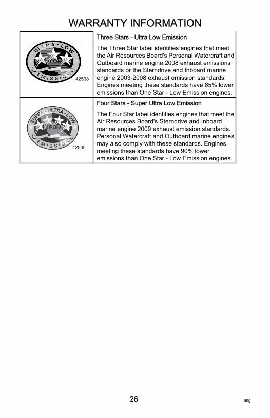
Three Stars ‑ Ultra Low Emission
The Three Star label identifies engines that meetthe Air Resources Board's Personal Watercraft andOutboard marine engine 2008 exhaust emissionsstandards or the Sterndrive and Inboard marineengine 2003‑2008 exhaust emission standards.Engines meeting these standards have 65% loweremissions than One Star ‑ Low Emission engines.
42539
Four Stars ‑ Super Ultra Low EmissionThe Four Star label identifies engines that meet theAir Resources Board's Sterndrive and Inboardmarine engine 2009 exhaust emission standards.Personal Watercraft and Outboard marine enginesmay also comply with these standards. Enginesmeeting these standards have 90% loweremissions than One Star ‑ Low Emission engines.
GENERAL INFORMATION
eng 27
Boater's ResponsibilitiesThe operator (driver) is responsible for the correct and safeoperation of the boat and safety of its occupants and generalpublic. It is strongly recommended that each operator (driver) readand understand this entire manual before operating the outboard.Be sure at least one additional person onboard is instructed in thebasics of starting and operating the outboard and boat handling incase the driver is unable to operate the boat.
Before Operating Your OutboardRead this manual carefully. Learn the difference in handlingcharacteristics between a jet drive boat and a propeller driven boat.If you have any questions, contact your dealer.
STEERING AT LOW SPEEDSUnlike propeller driven boats, the jet drive boat tends to losesteering control as less water is drawn in and expelled. Increasespeed slightly to regain steering.
MANEUVERABILITYThe jet drive is highly maneuverable at higher speeds, more so,than propeller driven boats. Use caution when turning to preventspin‑outs.
IN NEUTRALThe impeller will continue to rotate while the engine is in neutral.Although the approximate balancing of forward and reverse thrustwill minimize boat movement, the boat may tend to move slowlyforward or backward. This is normal for a direct‑drive jet drivenboat. The operator should be aware of this and use cautionwhenever the engine is running.Safety and operating information that is practiced, along with usinggood common sense, can help prevent personal injury and productdamage.This manual as well as safety labels posted on the outboard usethe following safety alerts1. to draw your attention to special safetyinstructions that should be followed.
1. These safety alerts follow ANSI standard Z535.6‑2006 for product safety information inproduct manuals, instructions, and other collateral materials.

GENERAL INFORMATION
28 eng
! DANGERIndicates a hazardous situation which, if not avoided, will resultin death or serious injury.
! WARNINGIndicates a hazardous situation which, if not avoided, could resultin death or serious injury.
! CAUTIONIndicates a hazardous situation which, if not avoided, could resultin minor or moderate injury.
NOTICEIndicates a situation which, if not avoided, could result in engineor major component failure.
IMPORTANT: Identifies information essential to the successfulcompletion of the task.NOTE: Indicates information that helps in the understanding of aparticular step or action.
Boat Horsepower Capacity
! WARNINGExceeding the boat's maximum horsepower rating can causeserious injury or death. Overpowering the boat can affect boatcontrol and flotation characteristics or break the transom. Do notinstall an engine that exceeds the boat's maximum power rating.
GENERAL INFORMATION
eng 29
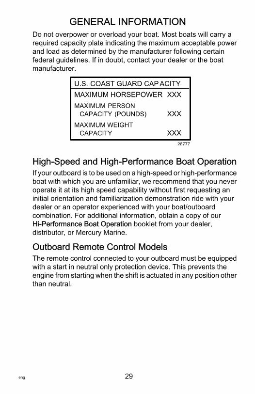
Do not overpower or overload your boat. Most boats will carry arequired capacity plate indicating the maximum acceptable powerand load as determined by the manufacturer following certainfederal guidelines. If in doubt, contact your dealer or the boatmanufacturer.
U.S. COAST GUARD CAP ACITYMAXIMUM HORSEPOWER XXXMAXIMUM PERSON CAPACITY (POUNDS) XXXMAXIMUM WEIGHT CAPACITY XXX
26777
High‑Speed and High‑Performance Boat OperationIf your outboard is to be used on a high‑speed or high‑performanceboat with which you are unfamiliar, we recommend that you neveroperate it at its high speed capability without first requesting aninitial orientation and familiarization demonstration ride with yourdealer or an operator experienced with your boat/outboardcombination. For additional information, obtain a copy of ourHi‑Performance Boat Operation booklet from your dealer,distributor, or Mercury Marine.
Outboard Remote Control ModelsThe remote control connected to your outboard must be equippedwith a start in neutral only protection device. This prevents theengine from starting when the shift is actuated in any position otherthan neutral.
GENERAL INFORMATION
30 eng
! WARNINGStarting the engine with the drive in gear can cause serious injuryor death. Never operate a boat that does not have aneutral‑safety‑protection device.
26779
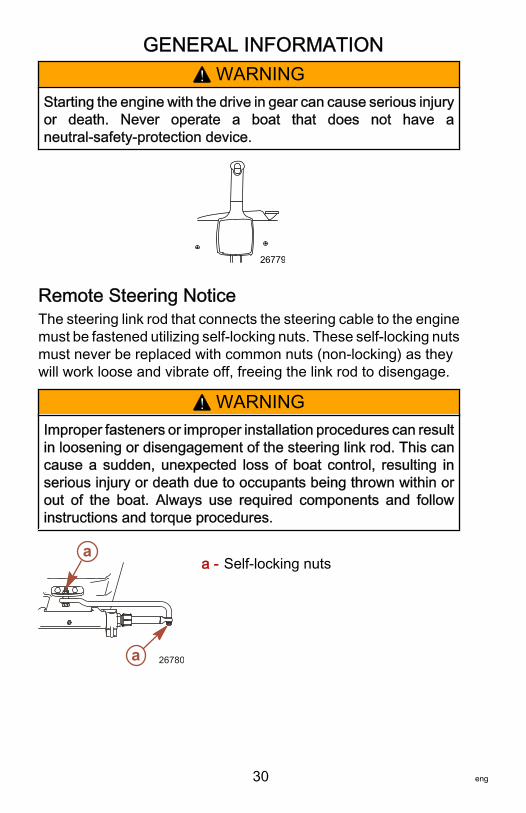
Remote Steering NoticeThe steering link rod that connects the steering cable to the enginemust be fastened utilizing self‑locking nuts. These self‑locking nutsmust never be replaced with common nuts (non‑locking) as theywill work loose and vibrate off, freeing the link rod to disengage.
! WARNINGImproper fasteners or improper installation procedures can resultin loosening or disengagement of the steering link rod. This cancause a sudden, unexpected loss of boat control, resulting inserious injury or death due to occupants being thrown within orout of the boat. Always use required components and followinstructions and torque procedures.
a - Self‑locking nutsa
a 26780
GENERAL INFORMATION
eng 31
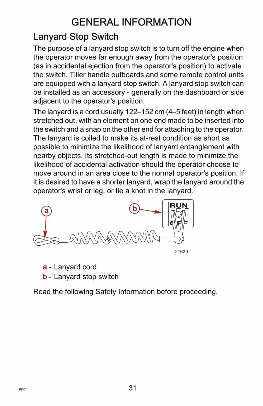
Lanyard Stop SwitchThe purpose of a lanyard stop switch is to turn off the engine whenthe operator moves far enough away from the operator's position(as in accidental ejection from the operator's position) to activatethe switch. Tiller handle outboards and some remote control unitsare equipped with a lanyard stop switch. A lanyard stop switch canbe installed as an accessory ‑ generally on the dashboard or sideadjacent to the operator's position.The lanyard is a cord usually 122–152 cm (4–5 feet) in length whenstretched out, with an element on one end made to be inserted intothe switch and a snap on the other end for attaching to the operator.The lanyard is coiled to make its at‑rest condition as short aspossible to minimize the likelihood of lanyard entanglement withnearby objects. Its stretched‑out length is made to minimize thelikelihood of accidental activation should the operator choose tomove around in an area close to the normal operator's position. Ifit is desired to have a shorter lanyard, wrap the lanyard around theoperator's wrist or leg, or tie a knot in the lanyard.
a - Lanyard cordb - Lanyard stop switch
Read the following Safety Information before proceeding.
21629
a b
GENERAL INFORMATION
32 eng
Important Safety Information: The purpose of a lanyard stop switchis to stop the engine when the operator moves far enough awayfrom the operator's position to activate the switch. This would occurif the operator accidentally falls overboard or moves within the boata sufficient distance from the operator's position. Falling overboardand accidental ejections are more likely to occur in certain typesof boats such as low sided inflatables, bass boats, highperformance boats, and light, sensitive handling fishing boatsoperated by a hand tiller. Falling overboard and accidentalejections are also likely to occur as a result of poor operatingpractices such as sitting on the back of the seat or gunwale atplaning speeds, standing at planing speeds, sitting on elevatedfishing boat decks, operating at planing speeds in shallow orobstacle infested waters, releasing your grip on a steering wheelor tiller handle that is pulling in one direction, drinking alcohol orconsuming drugs, or daring high speed boat maneuvers.While activation of the lanyard stop switch will stop the engineimmediately, a boat will continue to coast for some distancedepending upon the velocity and degree of any turn at shut down.However, the boat will not complete a full circle. While the boat iscoasting, it can cause injury to anyone in the boat's path asseriously as the boat would when under power.We strongly recommend that other occupants be instructed onproper starting and operating procedures should they be requiredto operate the engine in an emergency (e.g. if the operator isaccidentally ejected).
! WARNINGIf the operator falls out of the boat, stop the engine immediatelyto reduce the possibility of serious injury or death from beingstruck by the boat. Always properly connect the operator to thestop switch using a lanyard.
GENERAL INFORMATION
eng 33
! WARNINGAvoid serious injury or death from deceleration forces resultingfrom accidental or unintended stop switch activation. The boatoperator should never leave the operator's station without firstdisconnecting the stop switch lanyard from the operator.
Accidental or unintended activation of the switch during normaloperation is also a possibility. This could cause any, or all, of thefollowing potentially hazardous situations:• Occupants could be thrown forward due to unexpected loss
of forward motion ‑ a particular concern for passengers in thefront of the boat who could be ejected over the bow andpossibly struck by the gearcase or propeller.
• Loss of power and directional control in heavy seas, strongcurrent, or high winds.
• Loss of control when docking.
KEEP THE LANYARD STOP SWITCH AND LANYARD CORDIN GOOD OPERATING CONDITIONBefore each use, check to ensure the lanyard stop switch worksproperly. Start the engine and stop it by pulling the lanyard cord. Ifthe engine does not stop, have the switch repaired beforeoperating the boat.Before each use, visually inspect the lanyard cord to ensure it is ingood working condition and that there are no breaks, cuts, or wearto the cord. Check that the clips on the ends of the cord are in goodcondition. Replace any damaged or worn lanyard cords.
Stopping the Boat in an EmergencyA jet powered boat has emergency stopping capability unique tothis form of propulsion.
GENERAL INFORMATION
34 eng
! WARNINGUsing the emergency stopping capability of a jet drive unit willslow down the boat in an emergency. However, sudden stoppingmay cause the occupants of the boat to be thrown forward or outof the boat resulting in serious injury or death. Use caution whenperforming the emergency stopping procedure, and be sure topractice in a safe area.
In an emergency, putting the jet outboard into reverse and applyingreverse throttle can rapidly slow down the boat and reducestopping distance. However, such a maneuver may causeoccupants in the boat to be thrown forward or possibly out of theboat.
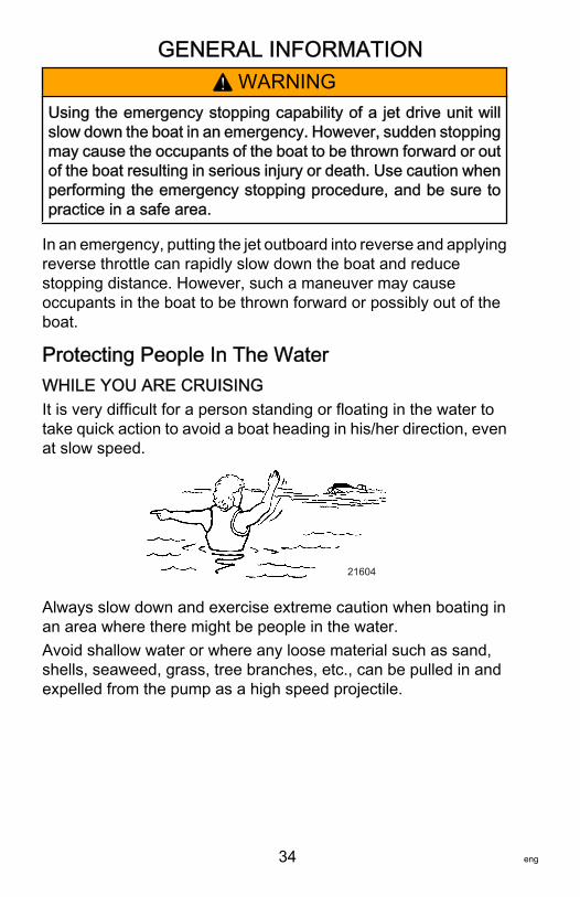
Protecting People In The WaterWHILE YOU ARE CRUISINGIt is very difficult for a person standing or floating in the water totake quick action to avoid a boat heading in his/her direction, evenat slow speed.
21604
Always slow down and exercise extreme caution when boating inan area where there might be people in the water.Avoid shallow water or where any loose material such as sand,shells, seaweed, grass, tree branches, etc., can be pulled in andexpelled from the pump as a high speed projectile.

GENERAL INFORMATION
eng 35
WHILE BOAT IS STATIONARY
! WARNINGAvoid injury resulting from contacting the rotating impeller orhaving hair, clothing, or loose objects drawn into the water intakeand wrapping around the impeller shaft. Stay away from thewater intake and never insert an object into the water intake orwater outlet nozzle when the engine is running.
Stop the engine immediately whenever a person is in the waternear the boat. The jet drive is always drawing water through thewater intake when the engine is running. Stay away from the waterintake located under the jet drive and never insert an object intothe water intake or outlet nozzle when the engine is running.
Passenger Safety Message ‑ Pontoon Boats andDeck BoatsWhenever the boat is in motion, observe the location of allpassengers. Do not allow any passengers to stand or use seatsother than those designated for traveling faster than idle speed. Asudden reduction in boat speed, such as plunging into a large waveor wake, a sudden throttle reduction, or a sharp change of boatdirection, could throw them over the front of the boat. Falling overthe front of the boat between the two pontoons will position themto be run over by the outboard.
BOATS HAVING AN OPEN FRONT DECKNo one should ever be on the deck in front of the fence while theboat is in motion. Keep all passengers behind the front fence orenclosure.
GENERAL INFORMATION
36 eng
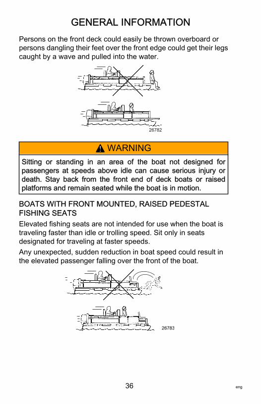
Persons on the front deck could easily be thrown overboard orpersons dangling their feet over the front edge could get their legscaught by a wave and pulled into the water.
26782
! WARNINGSitting or standing in an area of the boat not designed forpassengers at speeds above idle can cause serious injury ordeath. Stay back from the front end of deck boats or raisedplatforms and remain seated while the boat is in motion.
BOATS WITH FRONT MOUNTED, RAISED PEDESTALFISHING SEATSElevated fishing seats are not intended for use when the boat istraveling faster than idle or trolling speed. Sit only in seatsdesignated for traveling at faster speeds.Any unexpected, sudden reduction in boat speed could result inthe elevated passenger falling over the front of the boat.
26783
GENERAL INFORMATION
eng 37
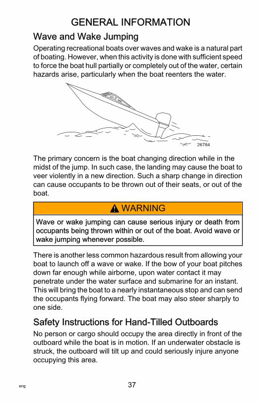
Wave and Wake JumpingOperating recreational boats over waves and wake is a natural partof boating. However, when this activity is done with sufficient speedto force the boat hull partially or completely out of the water, certainhazards arise, particularly when the boat reenters the water.
26784
The primary concern is the boat changing direction while in themidst of the jump. In such case, the landing may cause the boat toveer violently in a new direction. Such a sharp change in directioncan cause occupants to be thrown out of their seats, or out of theboat.
! WARNINGWave or wake jumping can cause serious injury or death fromoccupants being thrown within or out of the boat. Avoid wave orwake jumping whenever possible.
There is another less common hazardous result from allowing yourboat to launch off a wave or wake. If the bow of your boat pitchesdown far enough while airborne, upon water contact it maypenetrate under the water surface and submarine for an instant.This will bring the boat to a nearly instantaneous stop and can sendthe occupants flying forward. The boat may also steer sharply toone side.
Safety Instructions for Hand‑Tilled OutboardsNo person or cargo should occupy the area directly in front of theoutboard while the boat is in motion. If an underwater obstacle isstruck, the outboard will tilt up and could seriously injure anyoneoccupying this area.
GENERAL INFORMATION
38 eng
MODELS WITH CLAMP SCREWS:Some outboards come with transom bracket clamp screws. Theuse of clamp bracket screws alone, is insufficient to properly andsafely secure the outboard to the transom. Proper installation ofthe outboard includes bolting the engine to the boat through thetransom. Refer to Installation - Installing Outboard for morecomplete installation information.
! WARNINGFailure to correctly fasten the outboard could result in theoutboard propelling off the boat transom resulting in propertydamage, serious injury, or death. Before operation, the outboardmust be correctly installed with the required mounting hardware.Do not accelerate above idle speed in water that may containunderwater obstacles if the outboard is not attached to thetransom correctly.
If an obstacle is struck at planing speed and the outboard is notsecurely fastened to the transom, it is possible the outboard couldlift off the transom and land in the boat.
Exhaust EmissionsBE ALERT TO CARBON MONOXIDE POISONINGCarbon monoxide (CO) is a deadly gas that is present in theexhaust fumes of all internal combustion engines, including theengines that propel boats, and the generators that power boataccessories. By itself, CO is odorless, colorless, and tasteless, butif you can smell or taste engine exhaust, you are inhaling CO.Early symptoms of carbon monoxide poisoning, which are similarto the symptoms of seasickness and intoxication, includeheadache, dizziness, drowsiness, and nausea.
GENERAL INFORMATION
eng 39
! WARNINGInhaling engine exhaust gases can result in carbon monoxidepoisoning, which can lead to unconsciousness, brain damage, ordeath. Avoid exposure to carbon monoxide.Stay clear from exhaust areas when engine is running. Keep theboat well‑ventilated while at rest or underway.
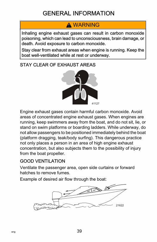
STAY CLEAR OF EXHAUST AREAS
41127
Engine exhaust gases contain harmful carbon monoxide. Avoidareas of concentrated engine exhaust gases. When engines arerunning, keep swimmers away from the boat, and do not sit, lie, orstand on swim platforms or boarding ladders. While underway, donot allow passengers to be positioned immediately behind the boat(platform dragging, teak/body surfing). This dangerous practicenot only places a person in an area of high engine exhaustconcentration, but also subjects them to the possibility of injuryfrom the boat propeller.
GOOD VENTILATIONVentilate the passenger area, open side curtains or forwardhatches to remove fumes.Example of desired air flow through the boat:
21622
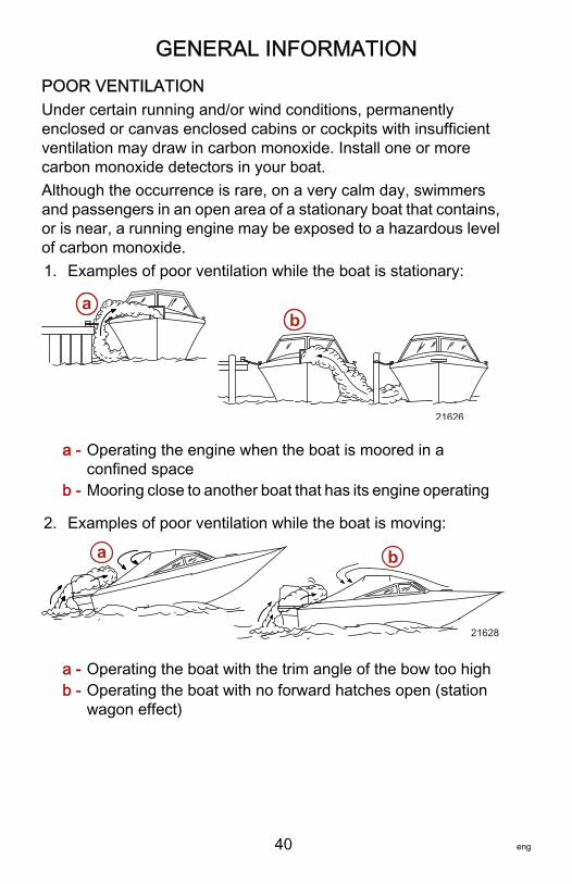
GENERAL INFORMATION
40 eng
POOR VENTILATIONUnder certain running and/or wind conditions, permanentlyenclosed or canvas enclosed cabins or cockpits with insufficientventilation may draw in carbon monoxide. Install one or morecarbon monoxide detectors in your boat.Although the occurrence is rare, on a very calm day, swimmersand passengers in an open area of a stationary boat that contains,or is near, a running engine may be exposed to a hazardous levelof carbon monoxide.1. Examples of poor ventilation while the boat is stationary:
a - Operating the engine when the boat is moored in aconfined space
b - Mooring close to another boat that has its engine operating
2. Examples of poor ventilation while the boat is moving:
a - Operating the boat with the trim angle of the bow too highb - Operating the boat with no forward hatches open (station
wagon effect)
21626
ab
a b
21628
GENERAL INFORMATION
eng 41
Selecting Accessories for Your OutboardGenuine Mercury Precision or Quicksilver Accessories have beenspecifically designed and tested for your outboard. Theseaccessories are available from Mercury Marine dealers.IMPORTANT: Check with your dealer before installingaccessories. The misuse of approved accessories or the use ofnonapproved accessories can damage the product.Some accessories not manufactured or sold by Mercury Marineare not designed to be safely used with your outboard or outboardoperating system. Acquire and read the installation, operation andmaintenance manuals for all your selected accessories.
Safe Boating SuggestionsIn order to safely enjoy the waterways, the operator should befamiliar with local and other governmental boating regulations andrestrictions, and consider the following suggestions.Use flotation devices. Have an approved personal flotation deviceof suitable size for each person aboard (it is the law) and have itreadily accessible.Do not overload your boat. Most boats are rated and certified formaximum load (weight) capacities (refer to your boat capacityplate). If in doubt, contact your dealer or the boats manufacturer.Perform safety checks and required maintenance. Follow a regularschedule and ensure that all repairs are properly made.Know and obey all nautical rules and laws of the waterways. Boatoperators should complete a boating safety course. Courses areoffered in the U.S.A. by 1) The U.S. Coast Guard Auxiliary, 2) ThePower Squadron, 3) The Red Cross and 4) any state boating lawenforcement agency. Inquiries may be made to the BoatingHotline, 1‑800‑368‑5647 or the Boat U.S. Foundation informationnumber 1‑800‑336‑BOAT.
GENERAL INFORMATION
42 eng
Make sure everyone in the boat is properly seated. Do not allowanyone to sit or ride on any part of the boat that was not intendedfor such use. This includes the back of seats, gunwales, transom,bow, decks, raised fishing seats, any rotating fishing seat; oranywhere that an unexpected acceleration, sudden stopping,unexpected loss of boat control, or sudden boat movement couldcause a person to be thrown overboard or into the boat.Never be under the influence of alcohol or drugs while boating (itis the law). Alcohol or drug use impairs judgment and greatlyreduces the ability to react quickly.Prepare other boat operators. Instruct at least one other person onboard in the basics of starting and operating the jet drive, and boathandling, in case the driver becomes disabled or falls overboard.Passenger boarding. Stop the engine whenever passengers areboarding, unloading, or are near the back (stern) of the boat. Justshifting the outboard into neutral is not sufficient.Be alert. The operator of the boat is responsible by law to maintaina proper lookout by sight and hearing. The operator must have anunobstructed view particularly to the front. No passengers, load,or fishing seats should block the operators view when operatingthe boat above idle speed.Avoid shallow water conditions. Never operate the jet drive invery shallow water or where there is a noticeable amount of floatingdebris or weeks. Always be in at least 61 to 91 cm (2 to 3 ft.) ofwater. Any loose material such as sand, shells, seaweed, grass,tree branches, etc., can be pulled in by the pump. This may notonly block the water flow and cause lost of steering control, but canbe expelled from the rear of the pump as a high‑speed projectile.Watch for boat movement in neutral. When the jet drive is inneutral, the drive impeller continues to rotate. Although theapproximate balancing of forward and reverse thrust will minimizeboat movement, the boat may tend to move slowly forward orbackward. This is normal for a direct‑drive jet driven boat. Theoperator should be aware of this and use caution whenever theengine is running.
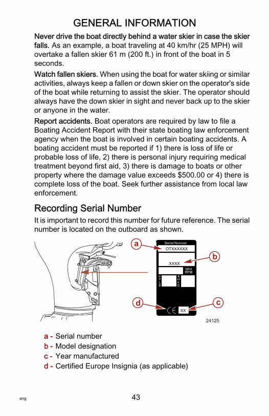
GENERAL INFORMATION
eng 43
Never drive the boat directly behind a water skier in case the skierfalls. As an example, a boat traveling at 40 km/hr (25 MPH) willovertake a fallen skier 61 m (200 ft.) in front of the boat in 5seconds.Watch fallen skiers. When using the boat for water skiing or similaractivities, always keep a fallen or down skier on the operator's sideof the boat while returning to assist the skier. The operator shouldalways have the down skier in sight and never back up to the skieror anyone in the water.Report accidents. Boat operators are required by law to file aBoating Accident Report with their state boating law enforcementagency when the boat is involved in certain boating accidents. Aboating accident must be reported if 1) there is loss of life orprobable loss of life, 2) there is personal injury requiring medicaltreatment beyond first aid, 3) there is damage to boats or otherproperty where the damage value exceeds $500.00 or 4) there iscomplete loss of the boat. Seek further assistance from local lawenforcement.
Recording Serial NumberIt is important to record this number for future reference. The serialnumber is located on the outboard as shown.
a - Serial numberb - Model designationc - Year manufacturedd - Certified Europe Insignia (as applicable)
XX
OTXXXXXX
XXXX
ab
cd
24125
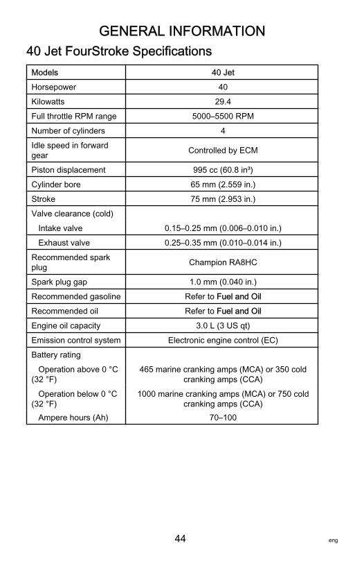
GENERAL INFORMATION
44 eng
40 Jet FourStroke SpecificationsModels 40 JetHorsepower 40Kilowatts 29.4Full throttle RPM range 5000–5500 RPMNumber of cylinders 4Idle speed in forwardgear Controlled by ECM
Piston displacement 995 cc (60.8 in³)Cylinder bore 65 mm (2.559 in.)Stroke 75 mm (2.953 in.)Valve clearance (cold) Intake valve 0.15–0.25 mm (0.006–0.010 in.) Exhaust valve 0.25–0.35 mm (0.010–0.014 in.)Recommended sparkplug Champion RA8HC
Spark plug gap 1.0 mm (0.040 in.)Recommended gasoline Refer to Fuel and OilRecommended oil Refer to Fuel and OilEngine oil capacity 3.0 L (3 US qt)Emission control system Electronic engine control (EC)Battery rating Operation above 0 °C(32 °F)
465 marine cranking amps (MCA) or 350 coldcranking amps (CCA)
Operation below 0 °C(32 °F)
1000 marine cranking amps (MCA) or 750 coldcranking amps (CCA)
Ampere hours (Ah) 70–100
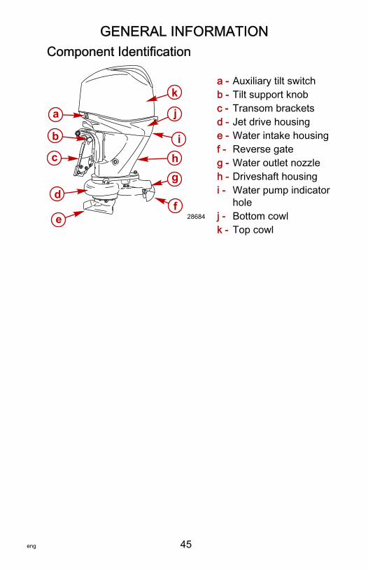
GENERAL INFORMATION
eng 45
Component Identification
a - Auxiliary tilt switchb - Tilt support knobc - Transom bracketsd - Jet drive housinge - Water intake housingf - Reverse gateg - Water outlet nozzleh - Driveshaft housingi - Water pump indicator
holej - Bottom cowlk - Top cowl
a
b
c
d
ef
ghi
j
k
28684
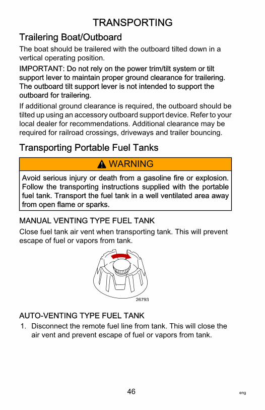
TRANSPORTING
46 eng
Trailering Boat/OutboardThe boat should be trailered with the outboard tilted down in avertical operating position.IMPORTANT: Do not rely on the power trim/tilt system or tiltsupport lever to maintain proper ground clearance for trailering.The outboard tilt support lever is not intended to support theoutboard for trailering.If additional ground clearance is required, the outboard should betilted up using an accessory outboard support device. Refer to yourlocal dealer for recommendations. Additional clearance may berequired for railroad crossings, driveways and trailer bouncing.
Transporting Portable Fuel Tanks
! WARNINGAvoid serious injury or death from a gasoline fire or explosion.Follow the transporting instructions supplied with the portablefuel tank. Transport the fuel tank in a well ventilated area awayfrom open flame or sparks.
MANUAL VENTING TYPE FUEL TANKClose fuel tank air vent when transporting tank. This will preventescape of fuel or vapors from tank.
26793
AUTO-VENTING TYPE FUEL TANK1. Disconnect the remote fuel line from tank. This will close the
air vent and prevent escape of fuel or vapors from tank.
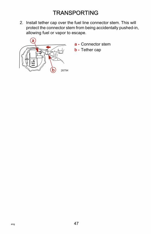
TRANSPORTING
eng 47
2. Install tether cap over the fuel line connector stem. This willprotect the connector stem from being accidentally pushed‑in,allowing fuel or vapor to escape.
a - Connector stemb - Tether cap
F
a
b 26794
FUEL & OIL
48 eng
Fuel RecommendationsIMPORTANT: Use of improper gasoline can damage yourengine. Engine damage resulting from the use of impropergasoline is considered misuse of the engine, and damagecaused thereby will not be covered under the limited warranty.
FUEL RATINGSMercury Marine engines will operate satisfactorily when using amajor brand of unleaded gasoline meeting the followingspecifications:USA and Canada ‑ having a posted pump Octane Rating of 87 (R+M)/2 minimum. Premium gasoline (92 [R+M]/2 Octane) is alsoacceptable. Do not use leaded gasoline.Outside USA and Canada ‑ having a posted pump Octane Ratingof 90 RON minimum. Premium gasoline (98 RON) is alsoacceptable. If unleaded gasoline is not available, use a majorbrand of leaded gasoline.
USING REFORMULATED (OXYGENATED) GASOLINES(USA ONLY)This type of gasoline is required in certain areas of the USA. The2 types of oxygenates used in these fuels are alcohol (ethanol) orether (MTBE or ETBE). If ethanol is the oxygenate that is used inthe gasoline in your area, refer to Gasolines ContainingAlcohol.These reformulated gasolines are acceptable for use in yourMercury Marine engine.
GASOLINES CONTAINING ALCOHOLIf the gasoline in your area contains either methanol (methylalcohol) or ethanol (ethyl alcohol), you should be aware of certainadverse effects that can occur. These adverse effects are moresevere with methanol. Increasing the percentage of alcohol in thefuel can also worsen these adverse effects.Some of these adverse effects are caused because the alcohol inthe gasoline can absorb moisture from the air, resulting in aseparation of the water/alcohol from the gasoline in the fuel tank.
FUEL & OIL
eng 49
The fuel system components on your Mercury Marine engine willwithstand up to 10% alcohol content in the gasoline. We do notknow what percentage your boat's fuel system will withstand.Contact your boat manufacturer for specific recommendations onthe boat's fuel system components (fuel tanks, fuel lines, andfittings). Be aware that gasolines containing alcohol may causeincreased:• Corrosion of metal parts• Deterioration of rubber or plastic parts• Fuel permeation through rubber fuel lines• Starting and operating difficulties
! WARNINGFuel leakage is a fire or explosion hazard, which can causeserious injury or death. Periodically inspect all fuel systemcomponents for leaks, softening, hardening, swelling, orcorrosion, particularly after storage. Any sign of leakage ordeterioration requires replacement before further engineoperation.
Because of possible adverse effects of alcohol in gasoline, it isrecommended that only alcohol‑free gasoline be used wherepossible. If only fuel containing alcohol is available, or if thepresence of alcohol is unknown, increased inspection frequencyfor leaks and abnormalities is required.IMPORTANT: When operating a Mercury Marine engine ongasoline containing alcohol, storage of gasoline in the fuel tank forlong periods should be avoided. Long periods of storage, commonto boats, create unique problems. In cars, alcohol‑blend fuelsnormally are consumed before they can absorb enough moistureto cause trouble, but boats often sit idle long enough for phaseseparation to take place. In addition, internal corrosion may takeplace during storage if alcohol has washed protective oil films frominternal components.
FUEL & OIL
50 eng
Low Permeation Fuel Hose RequirementRequired for outboards manufactured for sale, sold, or offered forsale in the United States.• The Environmental Protection Agency (EPA) requires that any
outboard manufactured after January 1, 2009 must use lowpermeation fuel hose for the primary fuel hose connecting thefuel tank to the outboard.
• Low permeation hose is USCG Type B1‑15 or Type A1‑15,defined as not exceeding 15/gm²/24 h with CE 10 fuel at 23 °Cas specified in SAE J 1527 ‑ marine fuel hose.
Filling Fuel Tank
! WARNINGAvoid serious injury or death from a gasoline fire or explosion.Use caution when filling fuel tanks. Always stop the engine anddo not smoke or allow open flames or sparks in the area whilefilling fuel tanks.
Fill fuel tanks outdoors away from heat, sparks, and open flames.Remove portable fuel tanks from boat to refill them.Always stop engine before refilling tanks.Do not completely fill the fuel tanks. Leave approximately 10% ofthe tank volume unfilled. Fuel will expand in volume as itstemperature rises and can leak under pressure if the tank iscompletely filled.
PORTABLE FUEL TANK PLACEMENT IN THE BOATPlace the fuel tank in the boat so the vent is higher than the fuellevel under normal boat operating conditions.
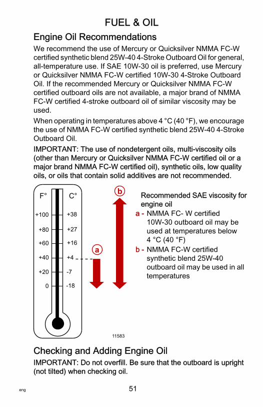
FUEL & OIL
eng 51
Engine Oil RecommendationsWe recommend the use of Mercury or Quicksilver NMMA FC‑Wcertified synthetic blend 25W‑40 4‑Stroke Outboard Oil for general,all‑temperature use. If SAE 10W‑30 oil is preferred, use Mercuryor Quicksilver NMMA FC‑W certified 10W‑30 4‑Stroke OutboardOil. If the recommended Mercury or Quicksilver NMMA FC‑Wcertified outboard oils are not available, a major brand of NMMAFC‑W certified 4‑stroke outboard oil of similar viscosity may beused.When operating in temperatures above 4 °C (40 °F), we encouragethe use of NMMA FC‑W certified synthetic blend 25W‑40 4‑StrokeOutboard Oil.IMPORTANT: The use of nondetergent oils, multi‑viscosity oils(other than Mercury or Quicksilver NMMA FC‑W certified oil or amajor brand NMMA FC‑W certified oil), synthetic oils, low qualityoils, or oils that contain solid additives are not recommended.
Recommended SAE viscosity forengine oil
a - NMMA FC‑ W certified10W‑30 outboard oil may beused at temperatures below4 °C (40 °F)
b - NMMA FC‑W certifiedsynthetic blend 25W‑40outboard oil may be used in alltemperatures
Checking and Adding Engine OilIMPORTANT: Do not overfill. Be sure that the outboard is upright(not tilted) when checking oil.
+20
+40
+60
+80
F° C°
0
+100
-7
+4
+16
+27
-18
+38
a
b
11583
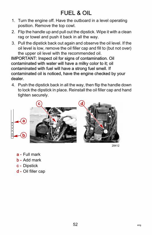
FUEL & OIL
52 eng
1. Turn the engine off. Have the outboard in a level operatingposition. Remove the top cowl.
2. Flip the handle up and pull out the dipstick. Wipe it with a cleanrag or towel and push it back in all the way.
3. Pull the dipstick back out again and observe the oil level. If theoil level is low, remove the oil filler cap and fill to (but not over)the upper oil level with the recommended oil.
IMPORTANT: Inspect oil for signs of contamination. Oilcontaminated with water will have a milky color to it; oilcontaminated with fuel will have a strong fuel smell. Ifcontaminated oil is noticed, have the engine checked by yourdealer.4. Push the dipstick back in all the way, then flip the handle down
to lock the dipstick in place. Reinstall the oil filler cap and handtighten securely.
a - Full markb - Add markc - Dipstickd - Oil filler cap
a
b
c d
28412
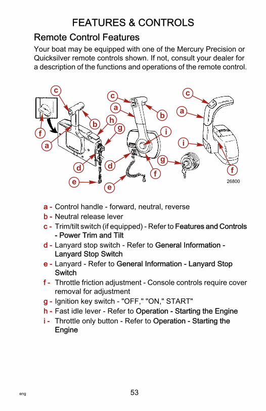
FEATURES & CONTROLS
eng 53
Remote Control FeaturesYour boat may be equipped with one of the Mercury Precision orQuicksilver remote controls shown. If not, consult your dealer fora description of the functions and operations of the remote control.
a - Control handle ‑ forward, neutral, reverseb - Neutral release leverc - Trim/tilt switch (if equipped) ‑ Refer to Features and Controls
‑ Power Trim and Tiltd - Lanyard stop switch ‑ Refer to General Information ‑
Lanyard Stop Switche - Lanyard ‑ Refer to General Information ‑ Lanyard Stop
Switchf - Throttle friction adjustment ‑ Console controls require cover
removal for adjustmentg - Ignition key switch ‑ "OFF," "ON," START"h - Fast idle lever ‑ Refer to Operation ‑ Starting the Enginei - Throttle only button ‑ Refer to Operation ‑ Starting the
Engine
fa
c
de
b h
ca
g
d
e
b
i
f
g
i
c
a
f26800
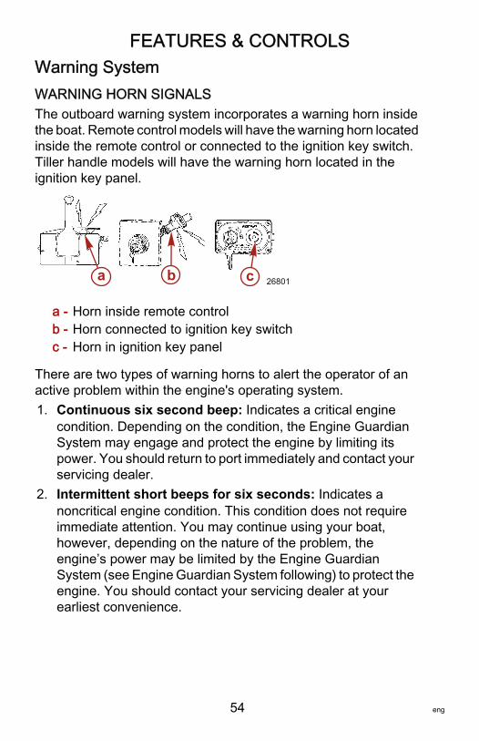
FEATURES & CONTROLS
54 eng
Warning SystemWARNING HORN SIGNALSThe outboard warning system incorporates a warning horn insidethe boat. Remote control models will have the warning horn locatedinside the remote control or connected to the ignition key switch.Tiller handle models will have the warning horn located in theignition key panel.
a - Horn inside remote controlb - Horn connected to ignition key switchc - Horn in ignition key panel
There are two types of warning horns to alert the operator of anactive problem within the engine's operating system.1. Continuous six second beep: Indicates a critical engine
condition. Depending on the condition, the Engine GuardianSystem may engage and protect the engine by limiting itspower. You should return to port immediately and contact yourservicing dealer.
2. Intermittent short beeps for six seconds: Indicates anoncritical engine condition. This condition does not requireimmediate attention. You may continue using your boat,however, depending on the nature of the problem, theengine’s power may be limited by the Engine GuardianSystem (see Engine Guardian System following) to protect theengine. You should contact your servicing dealer at yourearliest convenience.
a b c 26801
FEATURES & CONTROLS
eng 55
It is important to note that in either of the above scenarios, the hornwill only sound one time. If you key the engine off and restart it, thehorn will sound again, one time, if the fault is still present. For visualdisplay of the specific engine functions and additional engine data,refer to SmartCraft Product information, following.The operator is able to correct a couple engine problems indicatedby the warning horn. These conditions are as follows:• Cooling system (water pressure or engine temperature)
problem. The warning horn will sound Intermittent short beepsfor six seconds. Stop the engine and check the water intakeholes in the gearcase for obstruction.
• Low oil pressure problem. The warning horn will sound acontinuous six second beep. Stop the engine and check forlow engine oil level. Refer to Fuel and Oil – Checking andAdding Engine Oil.
ENGINE GUARDIAN SYSTEMThe Engine Guardian System monitors the critical sensors on theengine for any early indications of problems. Engine Guardian isfunctional whenever your engine is operating, so you never haveto be concerned about whether or not you are protected. Thesystem will respond to a problem by sounding the warning horn forsix seconds and/or reducing engine power in order to provideengine protection.If the Guardian System has been activated, reduce throttle speed.The problem will need to be identified and corrected, if possible.The system must be reset before the engine will operate at higherspeeds. Moving the throttle lever back to the idle position will resetthe system.
SMARTCRAFT PRODUCTA Mercury SmartCraft System instrument package can bepurchased for this outboard. A few of the functions the instrumentpackage will display are engine RPM, coolant temperature, oilpressure, water pressure, battery voltage, fuel consumption, andengine operating hours.
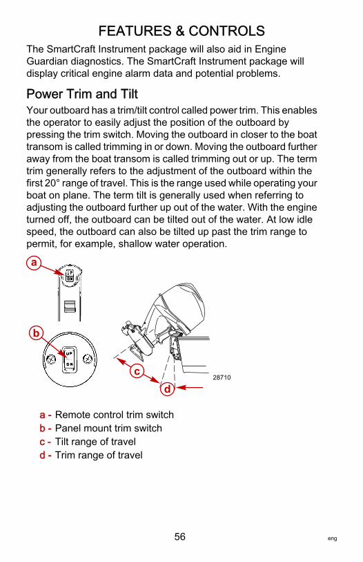
FEATURES & CONTROLS
56 eng
The SmartCraft Instrument package will also aid in EngineGuardian diagnostics. The SmartCraft Instrument package willdisplay critical engine alarm data and potential problems.
Power Trim and TiltYour outboard has a trim/tilt control called power trim. This enablesthe operator to easily adjust the position of the outboard bypressing the trim switch. Moving the outboard in closer to the boattransom is called trimming in or down. Moving the outboard furtheraway from the boat transom is called trimming out or up. The termtrim generally refers to the adjustment of the outboard within thefirst 20° range of travel. This is the range used while operating yourboat on plane. The term tilt is generally used when referring toadjusting the outboard further up out of the water. With the engineturned off, the outboard can be tilted out of the water. At low idlespeed, the outboard can also be tilted up past the trim range topermit, for example, shallow water operation.
a - Remote control trim switchb - Panel mount trim switchc - Tilt range of traveld - Trim range of travel
d
a
b
c28710
FEATURES & CONTROLS
eng 57
POWER TRIM OPERATIONWith most boats, operating around the middle of the trim range willgive satisfactory results. However, to take full advantage of thetrimming capability there may be times when you choose to trimyour outboard all the way in or out. Along with an improvement insome performance aspects comes a greater responsibility for theoperator, and this is being aware of some potential control hazards.The most significant control hazard is a pull or torque that can befelt on the steering wheel or tiller handle. This steering torqueresults from the outboard being trimmed so that the propeller shaftis not parallel to the water surface.
! WARNINGTrimming the outboard beyond a neutral steering condition mayresult in a pull on the steering wheel or tiller handle and loss ofboat control. Maintain control of the boat if trimming beyond aneutral steering condition.
Consider the following lists carefully.Trimming in or down can:• Lower the bow• Result in quicker planing off, especially with a heavy load or a
stern heavy boat• Generally improve the ride in choppy water• Increase steering torque or pull to the right (with the normal
right hand rotation propeller)• In excess, can lower the bow of some boats to a point where
they begin to plow with their bow in the water while on plane.This can result in an unexpected turn in either direction (calledbow steering or oversteering) if any turn is attempted, or if asignificant wave is encountered.

FEATURES & CONTROLS
58 eng
! WARNINGOperating the boat at high speeds with the outboard trimmedtoo far under can create excessive bow steer, resulting in theoperator losing control of the boat. Install the trim limit pin in aposition that prevents excessive trim under and operate theboat in a safe manner.• In rare circumstances, the owner may decide to limit the trim
in. This can be accomplished by repositioning the tilt stop pinsinto the desired transom bracket adjustment holes.
Trimming out or up can:• Lift the bow higher out of the water• Generally increase top speed• Increase clearance over submerged objects or a shallow
bottom• Increase steering torque or pull to the left at a normal
installation height (with the normal right hand rotationpropeller)
• In excess, can cause boat porpoising (bouncing) or propellerventilation
• Cause engine overheating if any cooling water intake holesare above the waterline
TILTING OPERATIONTo tilt outboard, shut off the engine and press the trim/tilt switch orauxiliary tilt switch to the up position. The outboard will tilt up untilthe switch is released or it reaches its maximum tilt position.1. Engage the tilt support lever, by rotating knob to bring the
support lever upward.2. Lower outboard to rest on the tilt support lever.
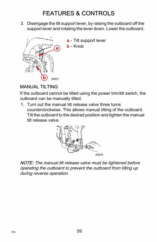
FEATURES & CONTROLS
eng 59
3. Disengage the tilt support lever, by raising the outboard off thesupport lever and rotating the lever down. Lower the outboard.
a - Tilt support leverb - Knob
MANUAL TILTINGIf the outboard cannot be tilted using the power trim/tilt switch, theoutboard can be manually tilted.1. Turn out the manual tilt release valve three turns
counterclockwise. This allows manual tilting of the outboard.Tilt the outboard to the desired position and tighten the manualtilt release valve.
26809
NOTE: The manual tilt release valve must be tightened beforeoperating the outboard to prevent the outboard from tilting upduring reverse operation.
a
b 28931

FEATURES & CONTROLS
60 eng
AUXILIARY TILT SWITCHThe auxiliary tilt switch can be used to tilt the outboard up or downusing the power trim system.
a - Auxiliary tilt switch
Throttle Grip Friction Adjustment ‑ Tiller HandleModelsThrottle grip friction knob ‑ Turn friction knob to set and maintainthe throttle at desired speed. Turn knob clockwise to tighten frictionand turn knob counterclockwise to loosen friction.
a - Loosen frictionb - Tighten friction
Steering Friction Adjustment ‑ Tiller Handle ModelsNOTE: Steering friction adjustment is only provided on models withtiller handles.Adjust this lever to achieve the desired steering friction (drag) onthe tiller handle. Move lever to the left to tighten friction or move tothe right to loosen friction.
a
28534
a b
19807
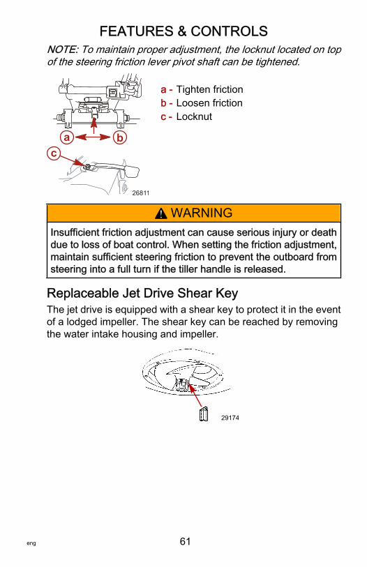
FEATURES & CONTROLS
eng 61
NOTE: To maintain proper adjustment, the locknut located on topof the steering friction lever pivot shaft can be tightened.
a - Tighten frictionb - Loosen frictionc - Locknut
! WARNINGInsufficient friction adjustment can cause serious injury or deathdue to loss of boat control. When setting the friction adjustment,maintain sufficient steering friction to prevent the outboard fromsteering into a full turn if the tiller handle is released.
Replaceable Jet Drive Shear KeyThe jet drive is equipped with a shear key to protect it in the eventof a lodged impeller. The shear key can be reached by removingthe water intake housing and impeller.
29174
a bc
26811
OPERATION
62 eng
Pre‑Starting Check List• Operator knows safe navigation, boating, and operating
procedures.• An approved personal flotation device of suitable size for each
person aboard and readily accessible (it is the law).• A ring type life buoy or buoyant cushion designed to be thrown
to a person in the water.• Know your boats maximum load capacity. Look at the boat
capacity plate.• Fuel supply OK.• Oil supply (oil injection) OK.• Ensure the boat drain plug is installed.• Arrange passengers and load in the boat so the weight is
distributed evenly and everyone is seated in a proper seat.• Tell someone where you are going and when you expect to
return.• It is illegal to operate a boat while under the influence of
alcohol or drugs.• Know the waters and area you will be boating; tides, currents,
sand bars, rocks, and other hazards.• Make inspection checks listed in Maintenance ‑ Inspection
and Maintenance Schedule.• Check steering for free operation.• Check for debris around the rudder and reverse gate which
may jam or hinder operation.• Before launching, examine the jet drive water intake for
obstructions which may prevent pumping of water.• Ensure the driveshaft bearing on the jet drive is lubricated.
Operating in Freezing TemperaturesIf there is a chance of ice forming on the water, the jet drive shouldbe removed and drained completely of water. If ice should form atthe water level inside the outboard driveshaft housing, it will blockwater flow to the engine causing possible damage. Do not start theengine until the ice is clear.
OPERATION
eng 63
Operating in Saltwater or Polluted WaterIf the boat is kept moored in the water, always tilt the outboard sothe water intake is completely out of water (except in freezingtemperatures) when not in use.Wash down the outboard exterior and flush out the exhaust outletof the jet drive with fresh water after each use. Each month, sprayMercury Precision or Quicksilver Corrosion Guard on externalmetal surfaces.NOTE: Do not spray on corrosion control anodes as this will reducethe effectiveness of the anodes.
Operating in Shallow WaterThe life of the impeller and water intake can be greatly increasedby avoiding the intake of sand and gravel. The intake suction willact like a dredge when the water intake comes close to the bottom.It is better to stop the engine and drift up to shore when landing,and to shove off with an oar when leaving. The engine can idlethrough areas of water less than 61 cm (2 ft) deep, but there shouldbe more than 61 cm (2 ft) of water under the boat when increasingspeed to reach full plane.Once the boat is on plane, the boat speed will prevent the ingestionof gravel and other debris from the bottom. The suction is stillpresent, but the water intake passes too quickly over the bottomto allow debris to be drawn into the water intake.When boating through shallow water areas, choose a course oftravel that avoids sharp rocks and other underwater obstacles thatcould damage the boat. Running the boat through these areas onfull plane may be helpful as the boat will be riding higher in thewater. If the boat gets stuck on the bottom, immediately stop theengine and move the boat to deeper water.
How the Jet Drive OperatesA jet driven boat has substantially different handling characteristicscompared to a propeller driven boat. It is recommended that theoperator adjusts to these characteristics by experimenting in openwater at both high and low speeds.

OPERATION
64 eng
The driveshaft driven impeller draws water up through the waterintake and then redirects it at a high pressure through the wateroutlet nozzle to create forward thrust. To obtain reverse, thereverse gate moves over the outlet nozzle to direct the water in theopposite direction.
a - Water intakeb - Water outlet nozzlec - Reverse gate
When the jet drive is in neutral, the impeller continues to rotate.However, the reverse gate is positioned so that some of theforward thrust is diverted to create reverse thrust. Thisapproximate balancing of forward and reverse thrust will minimizeany boat movement. Because the impeller is always rotating andcreating thrust when the engine is running, the boat may tend tomove slowly forward or backward. This is normal for a direct‑drivejet driven boat. The operator should be aware of this and usecaution whenever the engine is running.
a
c
b
29022
OPERATION
eng 65
! WARNINGAvoid injury resulting from contacting the rotating impeller orhaving hair, clothing, or loose objects drawn into the water intakeand wrapping around the impeller shaft. Stay away from thewater intake and never insert an object into the water intake orwater outlet nozzle when the engine is running.
The jet drive is always drawing water into the housing when theengine is running. Do not operate the jet drive with the grateremoved from the water intake. Keep hands, feet, hair, looseclothing, life jackets, etc., away from the water intake. Never insertan object into the water intake or water outlet nozzle when theengine is running.
Stopping the Boat in an EmergencyA jet powered boat has emergency stopping capability unique tothis form of propulsion.
! WARNINGUsing the emergency stopping capability of a jet drive unit willslow down the boat in an emergency. However, sudden stoppingmay cause the occupants of the boat to be thrown forward or outof the boat resulting in serious injury or death. Use caution whenperforming the emergency stopping procedure, and be sure topractice in a safe area.
In an emergency, putting the jet outboard into reverse and applyingreverse throttle can rapidly slow down the boat and reducestopping distance. However, such a maneuver may causeoccupants in the boat to be thrown forward or possibly out of theboat.
Steering the BoatThe jet drive is dependent on water jet thrust for steering the boat.If the water jet thrust should ever stop (water blockage, enginestops, etc.), the boat will slow to a stop. However, while slowingthere will be a reduced ability to steer the boat.
OPERATION
66 eng
! WARNINGSteering the vessel in a tight turn can result in loss of boat control.In some cases, the boat can spin out or roll over, causing seriousinjury or death. Avoid steering beyond the capabilities of thevessel, especially at high speeds.
! WARNINGA loss or reduction in water jet thrust will directly affect boatdirectional control, and may result in property damage, personalinjury, or death. Boat directional control can also be substantiallyreduced or lost altogether by a sudden loss of power such asrunning out of gas, quickly backing off the throttle, turning off theignition switch, activating the lanyard stop switch, or plugging thewater intake to the jet pump. Use caution when maneuvering athigh speeds in areas where debris (weeds, logs, gravel, etc.)could be picked up into the jet drive. The ability to take evasiveaction is dependent on sufficient water jet thrust to control theboat.
While steering the boat at engine speeds above idle, the boat willrespond quickly; but, due to the relatively flat‑bottom hulls and lackof a gearcase in the water, the boat will tend to skid on turns. Turnsmust be started early and use sufficient power to maintain steeringcontrol.
Mooring the BoatBe sure to tilt the jet drive out of the water when the boat is pulledonto a beach or tied to a dock in shallow water. Failure to do thismay cause the water intake housing to fill with sand or debris andcould prevent the outboard from cranking over for starting.
OPERATION
eng 67
Water Intake Blockage
! WARNINGA rotating impeller could cause injury if contact is made withhands, clothing, or tools. To avoid injury, keep hands and clothingaway from the inlet or outlet of the jetdrive, regardless of whetherthe boat is in the water. Secure tools and loose items to avoidbeing struck by projectiles as a result of contact with the rotatingimpeller, and to prevent damage to the impeller.
A large amount of debris being drawn into the water intake mayresult in a loss of power. Intake suction holding debris against thegrate will result in restricted water flow. Shutting the engine off mayallow the debris to fall off the intake grate allowing full power to berestored. If debris does not fall off the intake grate, the engine mustbe shut off and debris physically removed from the grate.
Clearing A Lodged Impeller
! WARNINGRotating the flywheel to free a lodged impeller can accidentallystart the engine, resulting in serious injury or death. Always turnthe ignition key or lanyard stop switch to the "OFF" position andremove all spark plug leads from the spark plugs.
It is possible for debris to lodge between the impeller and jethousing wall, especially after the engine has been stopped. Thiswill lock the driveshaft and will prevent the engine from being ableto crank over for starting. Following are steps for dislodging theimpeller.1. Position lanyard stop switch to the "OFF" position.2. Remove spark plug leads to prevent the engine from
accidentally starting.3. Remove flywheel or rewind cover and rotate the engine
flywheel counterclockwise.If this does not dislodge the impeller, it will be necessary to removethe six screws and water intake housing.

OPERATION
68 eng
Pre‑Starting Instructions1. Check the engine oil level.
28525
2. Ensure that the driveshaft bearing on the jet drive is lubricated.Refer to Maintenance - Lubrication Points.
28664
Engine Break‑in ProcedureIMPORTANT: Failure to follow the engine break‑in procedures canresult in poor performance throughout the life of the engine andcan cause engine damage. Always follow break‑in procedures.1. For the first hour of operation, run the engine at varied throttle
settings up to 3500 RPM or at approximately half throttle.2. For the second hour of operation, run the engine at varied
throttle settings up to 4500 RPM or at three‑quarter throttle,and during this period of time, run it at full throttle forapproximately one minute every ten minutes.
3. For the next eight hours of operation, avoid continuousoperation at full throttle for more than five minutes at a time.
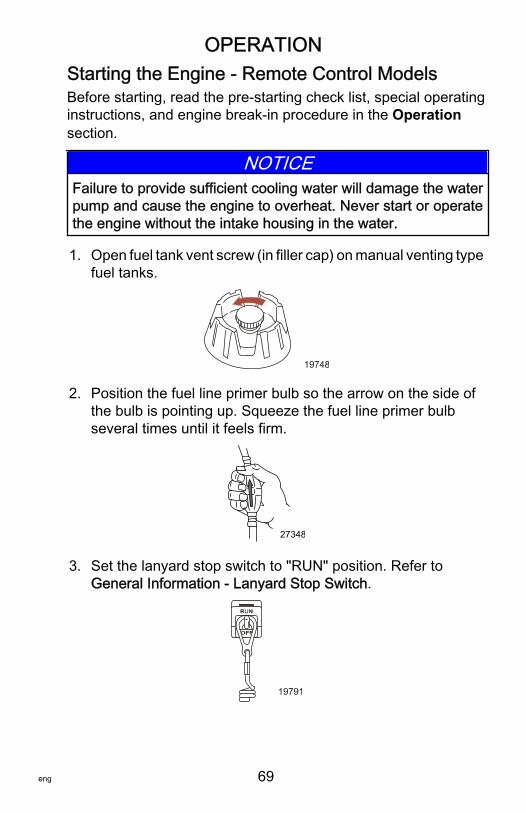
OPERATION
eng 69
Starting the Engine ‑ Remote Control ModelsBefore starting, read the pre‑starting check list, special operatinginstructions, and engine break‑in procedure in the Operationsection.
NOTICEFailure to provide sufficient cooling water will damage the waterpump and cause the engine to overheat. Never start or operatethe engine without the intake housing in the water.
1. Open fuel tank vent screw (in filler cap) on manual venting typefuel tanks.
19748
2. Position the fuel line primer bulb so the arrow on the side ofthe bulb is pointing up. Squeeze the fuel line primer bulbseveral times until it feels firm.
27348
3. Set the lanyard stop switch to "RUN" position. Refer toGeneral Information ‑ Lanyard Stop Switch.
19791
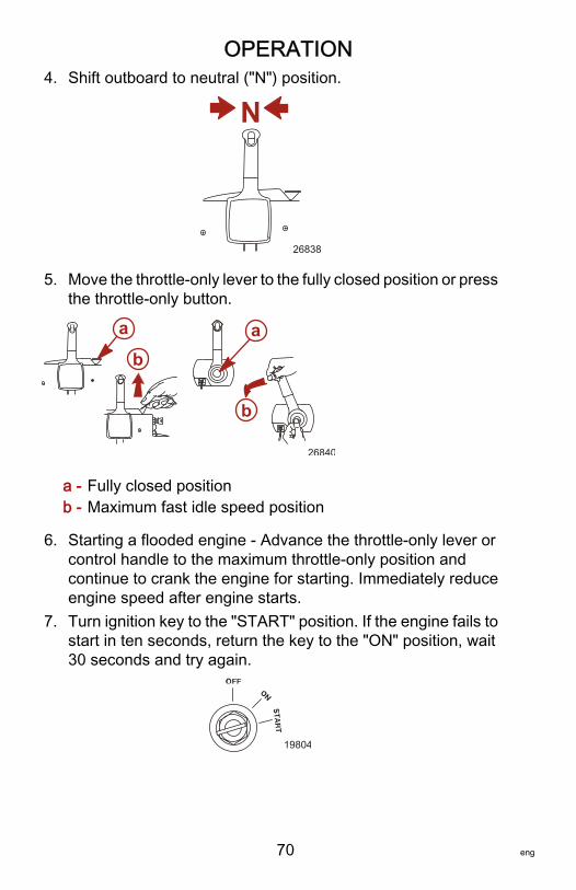
OPERATION
70 eng
4. Shift outboard to neutral ("N") position.
N
26838
5. Move the throttle‑only lever to the fully closed position or pressthe throttle‑only button.
a - Fully closed positionb - Maximum fast idle speed position
6. Starting a flooded engine ‑ Advance the throttle‑only lever orcontrol handle to the maximum throttle‑only position andcontinue to crank the engine for starting. Immediately reduceengine speed after engine starts.
7. Turn ignition key to the "START" position. If the engine fails tostart in ten seconds, return the key to the "ON" position, wait30 seconds and try again.
19804
a
ba
b
26840
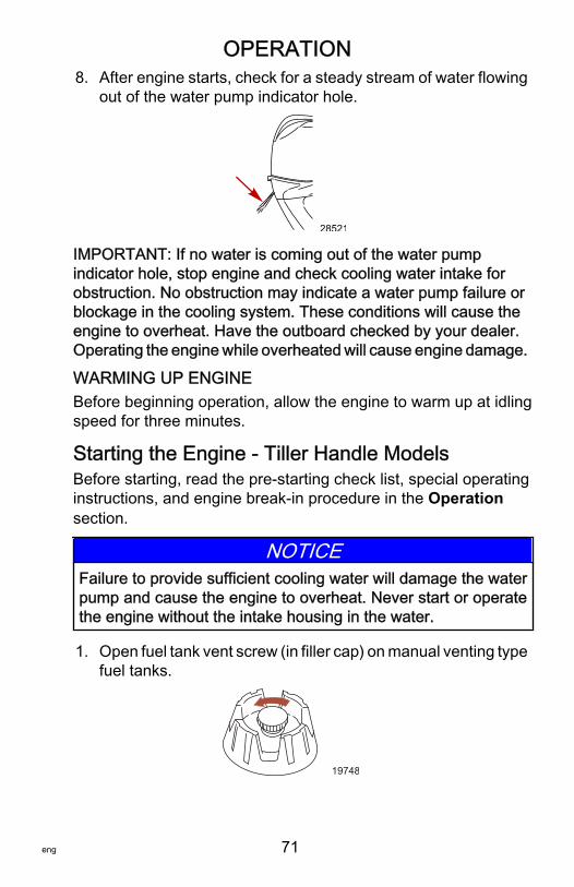
OPERATION
eng 71
8. After engine starts, check for a steady stream of water flowingout of the water pump indicator hole.
28521
IMPORTANT: If no water is coming out of the water pumpindicator hole, stop engine and check cooling water intake forobstruction. No obstruction may indicate a water pump failure orblockage in the cooling system. These conditions will cause theengine to overheat. Have the outboard checked by your dealer.Operating the engine while overheated will cause engine damage.
WARMING UP ENGINEBefore beginning operation, allow the engine to warm up at idlingspeed for three minutes.
Starting the Engine ‑ Tiller Handle ModelsBefore starting, read the pre‑starting check list, special operatinginstructions, and engine break‑in procedure in the Operationsection.
NOTICEFailure to provide sufficient cooling water will damage the waterpump and cause the engine to overheat. Never start or operatethe engine without the intake housing in the water.
1. Open fuel tank vent screw (in filler cap) on manual venting typefuel tanks.
19748
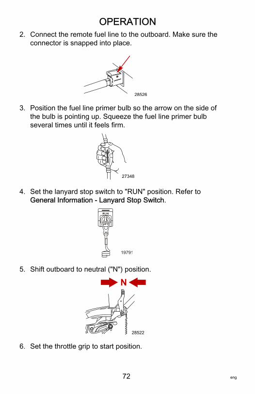
OPERATION
72 eng
2. Connect the remote fuel line to the outboard. Make sure theconnector is snapped into place.
28526
3. Position the fuel line primer bulb so the arrow on the side ofthe bulb is pointing up. Squeeze the fuel line primer bulbseveral times until it feels firm.
27348
4. Set the lanyard stop switch to "RUN" position. Refer toGeneral Information ‑ Lanyard Stop Switch.
19791
5. Shift outboard to neutral ("N") position.
N
28522
6. Set the throttle grip to start position.
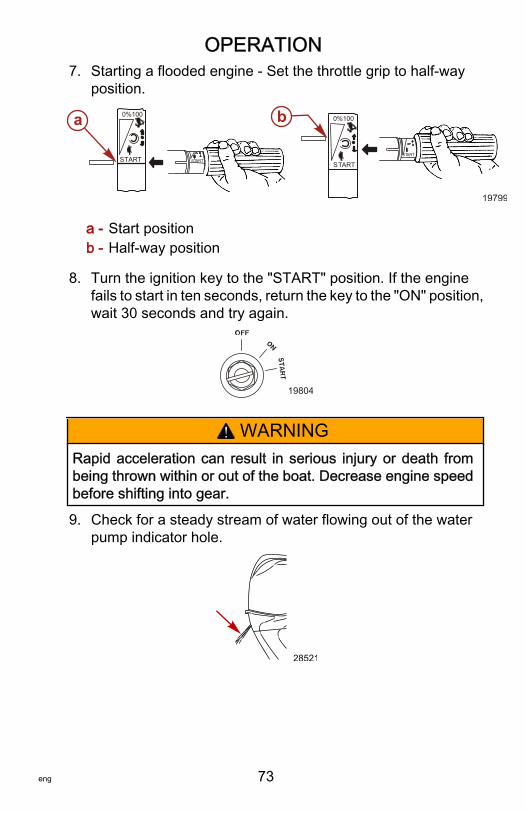
OPERATION
eng 73
7. Starting a flooded engine ‑ Set the throttle grip to half‑wayposition.
a - Start positionb - Half‑way position
8. Turn the ignition key to the "START" position. If the enginefails to start in ten seconds, return the key to the "ON" position,wait 30 seconds and try again.
19804
! WARNINGRapid acceleration can result in serious injury or death frombeing thrown within or out of the boat. Decrease engine speedbefore shifting into gear.
9. Check for a steady stream of water flowing out of the waterpump indicator hole.
28521
ART
0%100
STARTST
0%100
STARTSTART
a b
19799
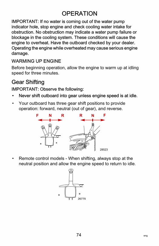
OPERATION
74 eng
IMPORTANT: If no water is coming out of the water pumpindicator hole, stop engine and check cooling water intake forobstruction. No obstruction may indicate a water pump failure orblockage in the cooling system. These conditions will cause theengine to overheat. Have the outboard checked by your dealer.Operating the engine while overheated may cause serious enginedamage.
WARMING UP ENGINEBefore beginning operation, allow the engine to warm up at idlingspeed for three minutes.
Gear ShiftingIMPORTANT: Observe the following:• Never shift outboard into gear unless engine speed is at idle.• Your outboard has three gear shift positions to provide
operation: forward, neutral (out of gear), and reverse.FNRF N R
28523
• Remote control models ‑ When shifting, always stop at theneutral position and allow the engine speed to return to idle.
26779

OPERATION
eng 75
• Tiller handle models ‑ Reduce the engine speed to idle beforeshifting.
26842
• Always shift the outboard into gear with a quick motion.• After shifting the outboard into gear, advance the remote
control lever or rotate the throttle grip (tiller handle) to increasespeed.
Stopping the Engine1. Remote control models ‑ Reduce engine speed and shift
outboard to neutral position. Turn ignition key to "OFF"position.
26843
2. Tiller handle models ‑ Reduce engine speed and shiftoutboard to neutral position. Push in the engine stop button orturn ignition key to "OFF" position.
26776
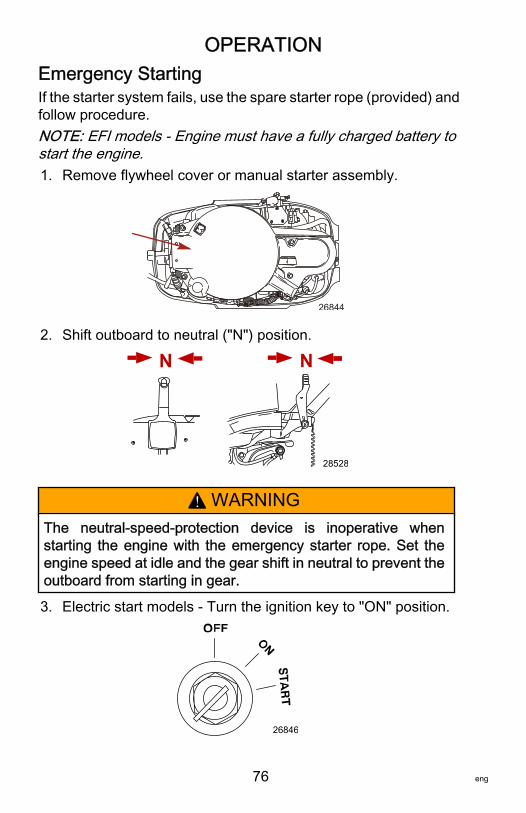
OPERATION
76 eng
Emergency StartingIf the starter system fails, use the spare starter rope (provided) andfollow procedure.NOTE: EFI models ‑ Engine must have a fully charged battery tostart the engine.1. Remove flywheel cover or manual starter assembly.
26844
2. Shift outboard to neutral ("N") position.
NN
28528
! WARNINGThe neutral‑speed‑protection device is inoperative whenstarting the engine with the emergency starter rope. Set theengine speed at idle and the gear shift in neutral to prevent theoutboard from starting in gear.
3. Electric start models ‑ Turn the ignition key to "ON" position.
26846

OPERATION
eng 77
! WARNINGHigh voltage is present any time the key is turned on, especiallywhen starting or operating the engine. Do not touch ignitioncomponents or metal test probes and stay clear of spark plugleads when performing live tests.
! WARNINGThe exposed moving flywheel can cause serious injury. Keepyour hands, hair, clothing, tools, and other objects away fromengine when starting or running the engine. Do not attempt toreinstall the flywheel cover or top cowl when engine is running.
4. Place the starter rope knot into the flywheel notch and windthe rope clockwise around the flywheel.
5. Pull the starter rope to start the engine.
26848
MAINTENANCE
78 eng
Outboard CareTo keep your outboard in the best operating condition, it isimportant that your outboard receive the periodic inspections andmaintenance listed in the Inspection and MaintenanceSchedule. We urge you to keep it maintained properly to ensurethe safety of you and your passengers, and retain its dependability.Record maintenance performed in the Maintenance Log at theback of this book. Save all maintenance work orders and receipts.
SELECTING REPLACEMENT PARTS FOR YOUROUTBOARDWe recommend using original Mercury Precision or Quicksilverreplacement parts and Genuine Lubricants.
EPA Emissions RegulationsAll new outboards manufactured by Mercury Marine are certifiedto the United States Environmental Protection Agency, asconforming to the requirements of the regulations for the control ofair pollution from new outboard motors. This certification iscontingent on certain adjustments set to factory standards. For thisreason, the factory procedure for servicing the product must bestrictly followed and, wherever practicable, returned to the originalintent of the design. Maintenance, replacement, or repair of theemission control devices and systems may be performed by anymarine spark ignition (SI) engine repair establishment or individual.
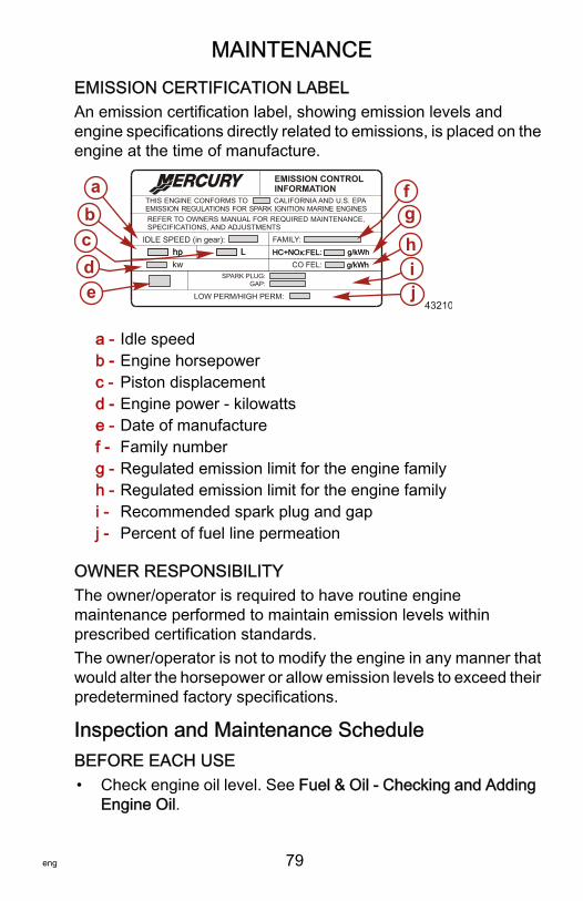
MAINTENANCE
eng 79
EMISSION CERTIFICATION LABELAn emission certification label, showing emission levels andengine specifications directly related to emissions, is placed on theengine at the time of manufacture.
a - Idle speedb - Engine horsepowerc - Piston displacementd - Engine power ‑ kilowattse - Date of manufacturef - Family numberg - Regulated emission limit for the engine familyh - Regulated emission limit for the engine familyi - Recommended spark plug and gapj - Percent of fuel line permeation
OWNER RESPONSIBILITYThe owner/operator is required to have routine enginemaintenance performed to maintain emission levels withinprescribed certification standards.The owner/operator is not to modify the engine in any manner thatwould alter the horsepower or allow emission levels to exceed theirpredetermined factory specifications.
Inspection and Maintenance ScheduleBEFORE EACH USE• Check engine oil level. See Fuel & Oil ‑ Checking and Adding
Engine Oil.
SPARK PLUG:GAP:
EMISSION CONTROLINFORMATION
THIS ENGINE CONFORMS TOEMISSION REGULATIONS FOR SPARK IGNITION MARINE ENGINES
CALIFORNIA AND U.S. EPA
REFER TO OWNERS MANUAL FOR REQUIRED MAINTENANCE,SPECIFICATIONS, AND ADJUSTMENTS
IDLE SPEED (in gear): FAMILY:
HC+NOx:FEL:
LOW PERM/HIGH PERM:
g/kWhhp L
edcba f
g
hi
HC+NOx:FEL: g/kWhhp LCO FEL: g/kWhkw g/kWh
j43210
MAINTENANCE
80 eng
• Check that lanyard stop switch stops the engine.• Visually inspect the fuel system for deterioration or leaks.• Inspect the outboard for tightness to the boat transom. If any
looseness of the outboard or mounting fasteners exist,retighten the outboard mounting fasteners. When looking forsigns of looseness, look for loss of outboard transom bracketmaterial or paint caused by movement between the outboardmounting fasteners and the outboard transom brackets. Alsolook for signs of movement between the outboard transombrackets and the boat transom.
• Check steering system for binding or loose components.• Visually check steering link rod fasteners for proper tightness.
See Steering Link Rod Fasteners.• Make sure the driveshaft bearing on the jet drive is lubricated.
See Lubrication Points.
AFTER EACH USE• Flush out the outboard cooling system if operating in salt or
polluted water. See Flushing the Cooling System.• If operating in saltwater, wash off all salt deposits and flush
out the exhaust outlet on the jet drive with fresh water.
EVERY 100 HOURS OF USE OR ONCE YEARLY,WHICHEVER OCCURS FIRST• Lubricate all lubrication points. Lubricate more frequently
when used in saltwater. See Lubrication Points.• Change engine oil and replace the oil filter. The oil should be
changed more often when the engine is operated underadverse conditions such as extended trolling. See ChangingEngine Oil.
• Inspect thermostat visually for corrosion and broken spring.Make sure thermostat closes completely at room temperature.1.
• Check engine fuel filter for contaminants. See Fuel System.• Check engine timing setup.1.
1. These items should be serviced by an authorized dealer.
MAINTENANCE
eng 81
• Check corrosion control anodes. Check more frequently whenused in saltwater. See Corrosion Control Anodes.
• Lubricate splines on the driveshaft.1.
• Check power trim fluid. See Checking Power Trim Fluid.• Inspect battery. See Battery Inspection.• Check control cable adjustments.1.
• Inspect timing belt. See Timing Belt Inspection.• Check tightness of bolts, nuts, and other fasteners.• Check cowl seals to make sure seals are intact and not
damaged.• Check internal cowl sound reduction foam (if equipped) to
make sure foam is intact and not damaged.• Check that the intake silencer (if equipped) is in place.• Check that the idle relief muffler (if equipped) is in place.• Check for loose hose clamps and rubber boots (if equipped)
on the air intake assembly.
EVERY 300 HOURS OF USE OR THREE YEARS• Replace spark plugs at first 300 hours or third year. After that,
inspect spark plugs every 300 hours or three years. Replacespark plugs as needed. See Spark Plug Inspection andReplacement.
• Replace water pump impeller (more often if overheatingoccurs or reduced water pressure is noted).1.
• Check and adjust valve clearance, if necessary.1.
BEFORE PERIODS OF STORAGE• Refer to storage procedure. See Storage section.
Flushing the Cooling SystemFlush the internal water passages of the outboard with fresh waterafter each use in salt, polluted, or muddy water. This will helpprevent a buildup of deposits from clogging the internal waterpassages.
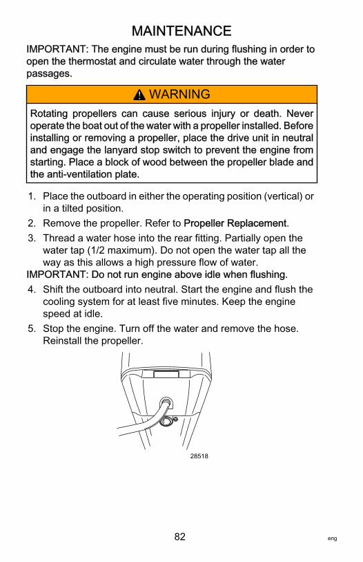
MAINTENANCE
82 eng
IMPORTANT: The engine must be run during flushing in order toopen the thermostat and circulate water through the waterpassages.
! WARNINGRotating propellers can cause serious injury or death. Neveroperate the boat out of the water with a propeller installed. Beforeinstalling or removing a propeller, place the drive unit in neutraland engage the lanyard stop switch to prevent the engine fromstarting. Place a block of wood between the propeller blade andthe anti‑ventilation plate.
1. Place the outboard in either the operating position (vertical) orin a tilted position.
2. Remove the propeller. Refer to Propeller Replacement.3. Thread a water hose into the rear fitting. Partially open the
water tap (1/2 maximum). Do not open the water tap all theway as this allows a high pressure flow of water.
IMPORTANT: Do not run engine above idle when flushing.4. Shift the outboard into neutral. Start the engine and flush the
cooling system for at least five minutes. Keep the enginespeed at idle.
5. Stop the engine. Turn off the water and remove the hose.Reinstall the propeller.
28518

MAINTENANCE
eng 83
Top Cowl Removal and InstallationREMOVAL1. Pull out the rear lock lever and remove the top cowl.
28439
INSTALLATION1. Lower the top cowl over the engine.2. Bring the front of the cowl down first and engage the front
hook. Lower the cowl into its seated position and applydownward pressure to the back of the cowl to lock it in place.Gently pull up on the back of cowl to make sure it is securelyfastened.
28445
Exterior CareYour outboard is protected with a durable baked enamel finish.Clean and wax often using marine cleaners and waxes.
MAINTENANCE
84 eng
Battery InspectionThe battery should be inspected at periodic intervals to ensureproper engine starting capability.IMPORTANT: Read the safety and maintenance instructionswhich accompany your battery.1. Turn off the engine before servicing the battery.2. Ensure the battery is secure against movement.3. Battery cable terminals should be clean, tight, and correctly
installed. Positive to positive and negative to negative.4. Ensure the battery is equipped with a nonconductive shield to
prevent accidental shorting of battery terminals.
Fuel System
! WARNINGFuel is flammable and explosive. Ensure that the key switch isoff and the lanyard is positioned so that the engine cannot start.Do not smoke or allow sources of spark or open flame in the areawhile servicing. Keep the work area well ventilated and avoidprolonged exposure to vapors. Always check for leaks beforeattempting to start the engine, and wipe up any spilled fuelimmediately.
Before servicing any part of the fuel system, stop the engine anddisconnect the battery. Drain the fuel system completely. Use anapproved container to collect and store the fuel. Wipe up anyspillage immediately. Material used to contain spillage must bedisposed of in an approved receptacle. Any fuel system servicemust be performed in a well‑ventilated area. Inspect anycompleted service work for sign of fuel leakage.
FUEL LINE INSPECTIONVisually inspect the fuel line and primer bulb for cracks, swelling,leaks, hardness, or other signs of deterioration or damage. If anyof these conditions are found, the fuel line or primer bulb must bereplaced.
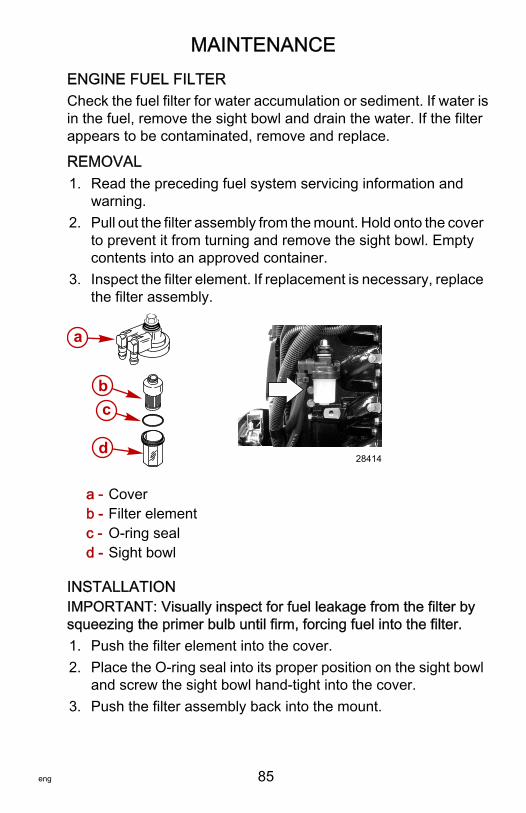
MAINTENANCE
eng 85
ENGINE FUEL FILTERCheck the fuel filter for water accumulation or sediment. If water isin the fuel, remove the sight bowl and drain the water. If the filterappears to be contaminated, remove and replace.
REMOVAL1. Read the preceding fuel system servicing information and
warning.2. Pull out the filter assembly from the mount. Hold onto the cover
to prevent it from turning and remove the sight bowl. Emptycontents into an approved container.
3. Inspect the filter element. If replacement is necessary, replacethe filter assembly.
a - Coverb - Filter elementc - O‑ring seald - Sight bowl
INSTALLATIONIMPORTANT: Visually inspect for fuel leakage from the filter bysqueezing the primer bulb until firm, forcing fuel into the filter.1. Push the filter element into the cover.2. Place the O‑ring seal into its proper position on the sight bowl
and screw the sight bowl hand‑tight into the cover.3. Push the filter assembly back into the mount.
a
bc
d28414
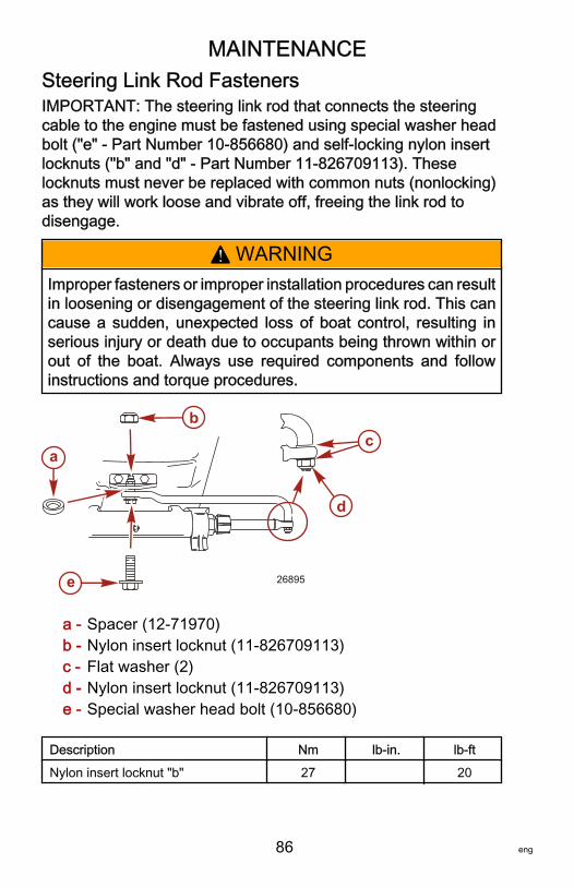
MAINTENANCE
86 eng
Steering Link Rod FastenersIMPORTANT: The steering link rod that connects the steeringcable to the engine must be fastened using special washer headbolt ("e" ‑ Part Number 10‑856680) and self‑locking nylon insertlocknuts ("b" and "d" ‑ Part Number 11‑826709113). Theselocknuts must never be replaced with common nuts (nonlocking)as they will work loose and vibrate off, freeing the link rod todisengage.
! WARNINGImproper fasteners or improper installation procedures can resultin loosening or disengagement of the steering link rod. This cancause a sudden, unexpected loss of boat control, resulting inserious injury or death due to occupants being thrown within orout of the boat. Always use required components and followinstructions and torque procedures.
a - Spacer (12‑71970)b - Nylon insert locknut (11‑826709113)c - Flat washer (2)d - Nylon insert locknut (11‑826709113)e - Special washer head bolt (10‑856680)
Description Nm lb‑in. lb‑ftNylon insert locknut "b" 27 20
a
b
e
d
c
26895
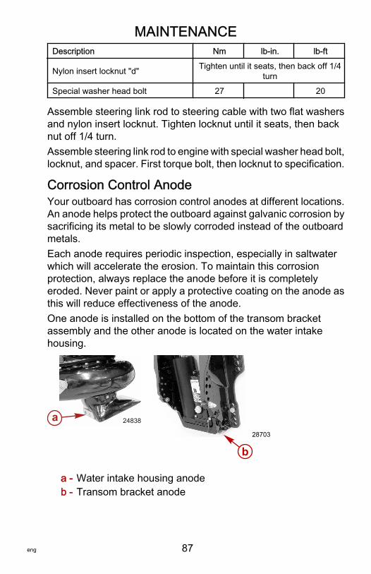
MAINTENANCE
eng 87
Description Nm lb‑in. lb‑ft
Nylon insert locknut "d" Tighten until it seats, then back off 1/4turn
Special washer head bolt 27 20
Assemble steering link rod to steering cable with two flat washersand nylon insert locknut. Tighten locknut until it seats, then backnut off 1/4 turn.Assemble steering link rod to engine with special washer head bolt,locknut, and spacer. First torque bolt, then locknut to specification.
Corrosion Control AnodeYour outboard has corrosion control anodes at different locations.An anode helps protect the outboard against galvanic corrosion bysacrificing its metal to be slowly corroded instead of the outboardmetals.Each anode requires periodic inspection, especially in saltwaterwhich will accelerate the erosion. To maintain this corrosionprotection, always replace the anode before it is completelyeroded. Never paint or apply a protective coating on the anode asthis will reduce effectiveness of the anode.One anode is installed on the bottom of the transom bracketassembly and the other anode is located on the water intakehousing.
a - Water intake housing anodeb - Transom bracket anode
a 24838
b28703
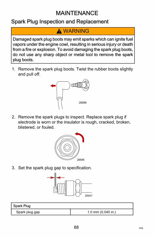
MAINTENANCE
88 eng
Spark Plug Inspection and Replacement
! WARNINGDamaged spark plug boots may emit sparks which can ignite fuelvapors under the engine cowl, resulting in serious injury or deathfrom a fire or explosion. To avoid damaging the spark plug boots,do not use any sharp object or metal tool to remove the sparkplug boots.
1. Remove the spark plug boots. Twist the rubber boots slightlyand pull off.
26899
2. Remove the spark plugs to inspect. Replace spark plug ifelectrode is worn or the insulator is rough, cracked, broken,blistered, or fouled.
26946
3. Set the spark plug gap to specification.
26947
Spark Plug Spark plug gap 1.0 mm (0.040 in.)
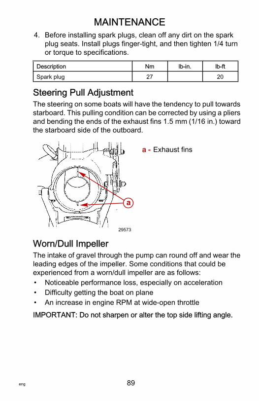
MAINTENANCE
eng 89
4. Before installing spark plugs, clean off any dirt on the sparkplug seats. Install plugs finger‑tight, and then tighten 1/4 turnor torque to specifications.
Description Nm lb‑in. lb‑ftSpark plug 27 20
Steering Pull AdjustmentThe steering on some boats will have the tendency to pull towardsstarboard. This pulling condition can be corrected by using a pliersand bending the ends of the exhaust fins 1.5 mm (1/16 in.) towardthe starboard side of the outboard.
a - Exhaust fins
Worn/Dull ImpellerThe intake of gravel through the pump can round off and wear theleading edges of the impeller. Some conditions that could beexperienced from a worn/dull impeller are as follows:• Noticeable performance loss, especially on acceleration• Difficulty getting the boat on plane• An increase in engine RPM at wide‑open throttleIMPORTANT: Do not sharpen or alter the top side lifting angle.
a
29573
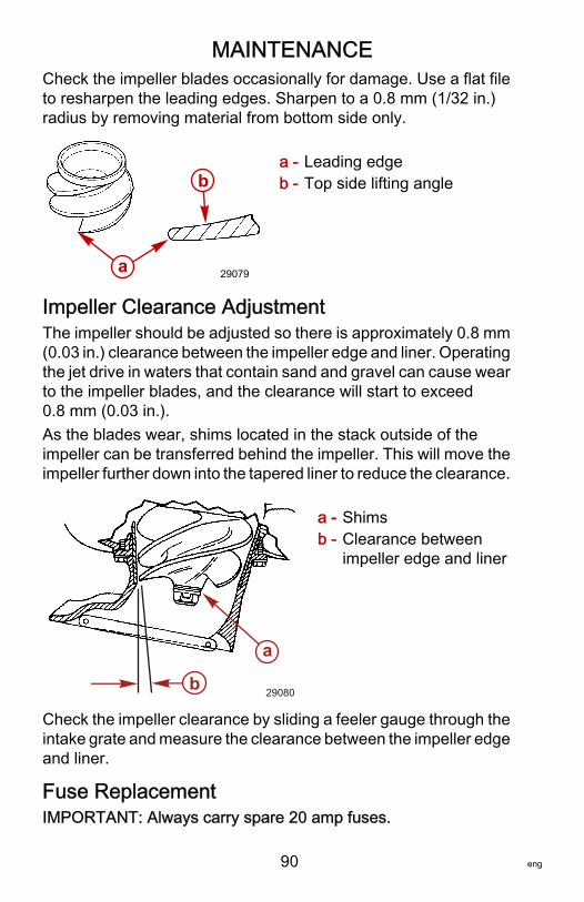
MAINTENANCE
90 eng
Check the impeller blades occasionally for damage. Use a flat fileto resharpen the leading edges. Sharpen to a 0.8 mm (1/32 in.)radius by removing material from bottom side only.
a - Leading edgeb - Top side lifting angle
Impeller Clearance AdjustmentThe impeller should be adjusted so there is approximately 0.8 mm(0.03 in.) clearance between the impeller edge and liner. Operatingthe jet drive in waters that contain sand and gravel can cause wearto the impeller blades, and the clearance will start to exceed0.8 mm (0.03 in.).As the blades wear, shims located in the stack outside of theimpeller can be transferred behind the impeller. This will move theimpeller further down into the tapered liner to reduce the clearance.
a - Shimsb - Clearance between
impeller edge and liner
Check the impeller clearance by sliding a feeler gauge through theintake grate and measure the clearance between the impeller edgeand liner.
Fuse ReplacementIMPORTANT: Always carry spare 20 amp fuses.
a
b
29079
a
b 29080
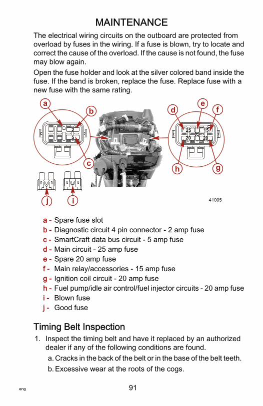
MAINTENANCE
eng 91
The electrical wiring circuits on the outboard are protected fromoverload by fuses in the wiring. If a fuse is blown, try to locate andcorrect the cause of the overload. If the cause is not found, the fusemay blow again.Open the fuse holder and look at the silver colored band inside thefuse. If the band is broken, replace the fuse. Replace fuse with anew fuse with the same rating.
a - Spare fuse slotb - Diagnostic circuit 4 pin connector ‑ 2 amp fusec - SmartCraft data bus circuit ‑ 5 amp fused - Main circuit ‑ 25 amp fusee - Spare 20 amp fusef - Main relay/accessories ‑ 15 amp fuseg - Ignition coil circuit ‑ 20 amp fuseh - Fuel pump/idle air control/fuel injector circuits ‑ 20 amp fusei - Blown fusej - Good fuse
Timing Belt Inspection1. Inspect the timing belt and have it replaced by an authorized
dealer if any of the following conditions are found.a. Cracks in the back of the belt or in the base of the belt teeth.b. Excessive wear at the roots of the cogs.
201525
20
25
j i
ab
c
de
f
gh
20
41005
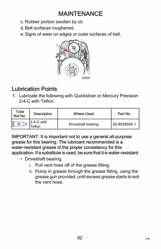
MAINTENANCE
92 eng
c. Rubber portion swollen by oil.d. Belt surfaces roughened.e. Signs of wear on edges or outer surfaces of belt.
26958
Lubrication Points1. Lubricate the following with Quicksilver or Mercury Precision
2‑4‑C with Teflon.
TubeRef No. Description Where Used Part No.
95 2-4-C withTeflon Driveshaft bearing 92-802859A 1
IMPORTANT: It is important not to use a general all‑purposegrease for this bearing. The lubricant recommended is awater‑resistant grease of the proper consistency for thisapplication. If a substitute is used, be sure that it is water‑resistant.
• Driveshaft bearingi. Pull vent hose off of the grease fitting.ii. Pump in grease through the grease fitting, using the
grease gun provided, until excess grease starts to exitthe vent hose.
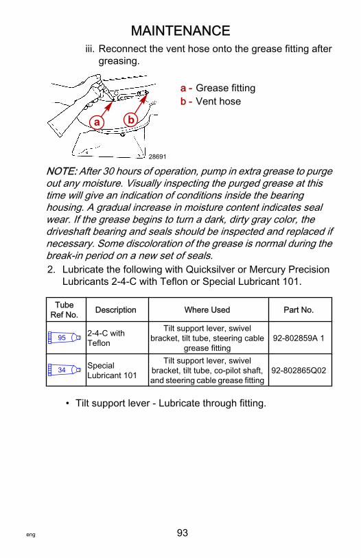
MAINTENANCE
eng 93
iii. Reconnect the vent hose onto the grease fitting aftergreasing.
a - Grease fittingb - Vent hose
NOTE: After 30 hours of operation, pump in extra grease to purgeout any moisture. Visually inspecting the purged grease at thistime will give an indication of conditions inside the bearinghousing. A gradual increase in moisture content indicates sealwear. If the grease begins to turn a dark, dirty gray color, thedriveshaft bearing and seals should be inspected and replaced ifnecessary. Some discoloration of the grease is normal during thebreak‑in period on a new set of seals.2. Lubricate the following with Quicksilver or Mercury Precision
Lubricants 2‑4‑C with Teflon or Special Lubricant 101.
TubeRef No. Description Where Used Part No.
95 2-4-C withTeflon
Tilt support lever, swivelbracket, tilt tube, steering cable
grease fitting92-802859A 1
34 SpecialLubricant 101
Tilt support lever, swivelbracket, tilt tube, co-pilot shaft,and steering cable grease fitting
92-802865Q02
• Tilt support lever ‑ Lubricate through fitting.
a b
28691
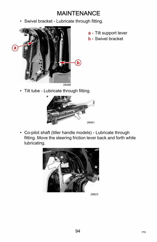
MAINTENANCE
94 eng
• Swivel bracket ‑ Lubricate through fitting.
a - Tilt support leverb - Swivel bracket
• Tilt tube ‑ Lubricate through fitting.
28461
• Co‑pilot shaft (tiller handle models) ‑ Lubricate throughfitting. Move the steering friction lever back and forth whilelubricating.
28823
a
b
28466

MAINTENANCE
eng 95
! WARNINGIncorrect cable lubrication can cause hydraulic lock, leading toserious injury or death from loss of boat control. Completelyretract the end of the steering cable before applying lubricant.
• Steering cable grease fitting (if equipped) ‑ Rotate steeringwheel to fully retract the steering cable end into theoutboard tilt tube. Lubricate through fitting.
a - Fittingb - Steering cable end
3. Lubricate the following with lightweight oil.• Steering link rod pivot points ‑ Lubricate points.
28471
ba
28468
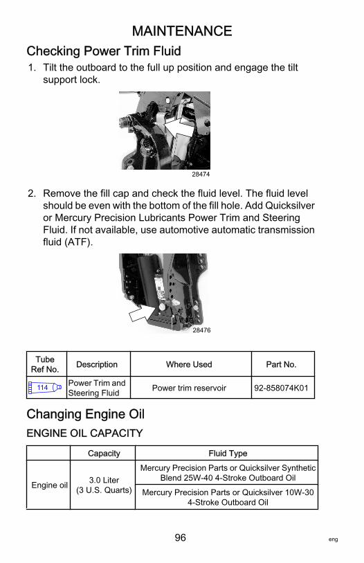
MAINTENANCE
96 eng
Checking Power Trim Fluid1. Tilt the outboard to the full up position and engage the tilt
support lock.
28474
2. Remove the fill cap and check the fluid level. The fluid levelshould be even with the bottom of the fill hole. Add Quicksilveror Mercury Precision Lubricants Power Trim and SteeringFluid. If not available, use automotive automatic transmissionfluid (ATF).
28476
TubeRef No. Description Where Used Part No.
114 Power Trim andSteering Fluid Power trim reservoir 92-858074K01
Changing Engine OilENGINE OIL CAPACITY
Capacity Fluid Type
Engine oil 3.0 Liter(3 U.S. Quarts)
Mercury Precision Parts or Quicksilver SyntheticBlend 25W‑40 4‑Stroke Outboard Oil
Mercury Precision Parts or Quicksilver 10W‑304‑Stroke Outboard Oil
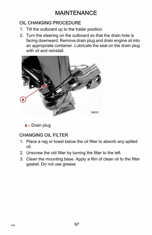
MAINTENANCE
eng 97
OIL CHANGING PROCEDURE1. Tilt the outboard up to the trailer position.2. Turn the steering on the outboard so that the drain hole is
facing downward. Remove drain plug and drain engine oil intoan appropriate container. Lubricate the seal on the drain plugwith oil and reinstall.
a - Drain plug
CHANGING OIL FILTER1. Place a rag or towel below the oil filter to absorb any spilled
oil.2. Unscrew the old filter by turning the filter to the left.3. Clean the mounting base. Apply a film of clean oil to the filter
gasket. Do not use grease
a
28633
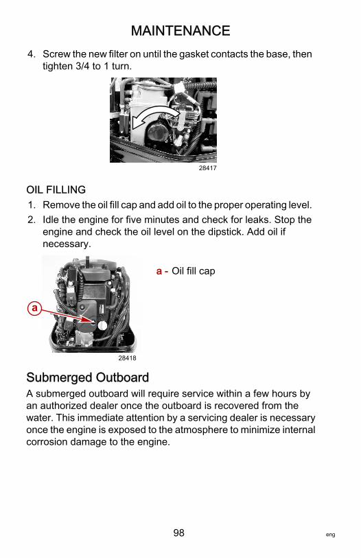
MAINTENANCE
98 eng
4. Screw the new filter on until the gasket contacts the base, thentighten 3/4 to 1 turn.
28417
OIL FILLING1. Remove the oil fill cap and add oil to the proper operating level.2. Idle the engine for five minutes and check for leaks. Stop the
engine and check the oil level on the dipstick. Add oil ifnecessary.
a - Oil fill cap
Submerged OutboardA submerged outboard will require service within a few hours byan authorized dealer once the outboard is recovered from thewater. This immediate attention by a servicing dealer is necessaryonce the engine is exposed to the atmosphere to minimize internalcorrosion damage to the engine.
a
28418
STORAGE
eng 99
Storage PreparationThe major consideration in preparing your outboard for storage isto protect it from rust, corrosion, and damage caused by freezingof trapped water.The following storage procedures should be followed to prepareyour outboard for out of season storage or prolonged storage (twomonths or longer).
NOTICEWithout sufficient cooling water, the engine, the water pump, andother components will overheat and suffer damage. Provide asufficient supply of water to the water inlets during operation.
FUEL SYSTEMIMPORTANT: Gasoline containing alcohol (ethanol or methanol)can cause a formation of acid during storage and can damage thefuel system. If the gasoline being used contains alcohol, it isadvisable to drain as much of the remaining gasoline as possiblefrom the fuel tank, remote fuel line, and engine fuel system.Fill the fuel tank and engine fuel system with treated (stabilized)fuel to help prevent formation of varnish and gum. Proceed withfollowing instructions.• Portable fuel tank ‑ Pour the required amount of gasoline
stabilizer (follow instructions on container) into fuel tank. Tipfuel tank back and forth to mix stabilizer with the fuel.
• Permanently installed fuel tank ‑ Pour the required amount ofgasoline stabilizer (follow instructions on container) into aseparate container and mix with approximately one liter (onequart) of gasoline. Pour this mixture into fuel tank.
• Remove the fuel filter sight bowl and empty contents in asuitable container. Refer to Maintenance - Fuel System forremoval and installation of filter. Add 3 cc (1/2 tsp.) of gasolinestabilizer into the fuel filter sight bowl and reinstall.
• Place the outboard in water or connect flushing attachment forcirculating cooling water. Run the engine for 15 minutes to fillthe engine fuel system.
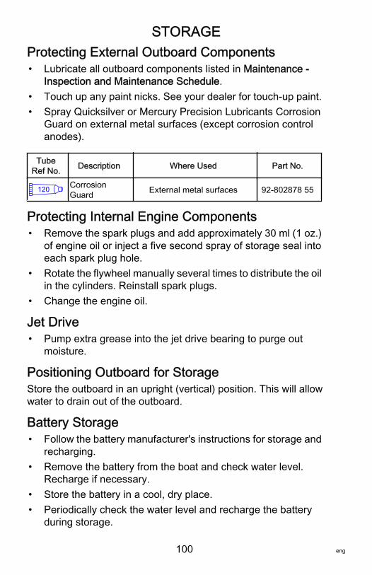
STORAGE
100 eng
Protecting External Outboard Components• Lubricate all outboard components listed in Maintenance ‑
Inspection and Maintenance Schedule.• Touch up any paint nicks. See your dealer for touch‑up paint.• Spray Quicksilver or Mercury Precision Lubricants Corrosion
Guard on external metal surfaces (except corrosion controlanodes).
TubeRef No. Description Where Used Part No.
120 CorrosionGuard External metal surfaces 92-802878 55
Protecting Internal Engine Components• Remove the spark plugs and add approximately 30 ml (1 oz.)
of engine oil or inject a five second spray of storage seal intoeach spark plug hole.
• Rotate the flywheel manually several times to distribute the oilin the cylinders. Reinstall spark plugs.
• Change the engine oil.
Jet Drive• Pump extra grease into the jet drive bearing to purge out
moisture.
Positioning Outboard for StorageStore the outboard in an upright (vertical) position. This will allowwater to drain out of the outboard.
Battery Storage• Follow the battery manufacturer's instructions for storage and
recharging.• Remove the battery from the boat and check water level.
Recharge if necessary.• Store the battery in a cool, dry place.• Periodically check the water level and recharge the battery
during storage.
TROUBLESHOOTING
eng 101
Starter Motor Will Not Crank the Engine (ElectricStart Models)POSSIBLE CAUSES• Blown fuse in the starting circuit. Refer to Maintenance
section.• Outboard is not shifted to neutral position.• Weak battery or battery connections are loose or corroded.• Ignition key switch failure.• Wiring or electrical connection faulty.• Starter motor or starter solenoid failure.
Engine Will Not StartPOSSIBLE CAUSES• Lanyard stop switch not in "RUN" position.• Incorrect starting procedure. Refer to Operation section.• Old or contaminated gasoline.• Engine flooded. Refer to Operation section.• Fuel is not reaching the engine.
a. Fuel tank is empty.b. Fuel tank vent not open or restricted.c. Fuel line is disconnected or kinked.d. Primer bulb not squeezed.e. Primer bulb check valve is faulty.f. Fuel filter is obstructed. Refer to Maintenance section.g. Fuel pump failure.h. Fuel tank filter obstructed.
• Blown fuse. Refer to Maintenance section.• Ignition system component failure.• Spark plugs fouled or defective. Refer to Maintenance section.
TROUBLESHOOTING
102 eng
Engine Runs ErraticallyPOSSIBLE CAUSES• Guardian System activated. Refer to Features & Controls -
Warning System.• Spark plugs fouled or defective. Refer to Maintenance section.• Incorrect setup and adjustments.• Fuel is being restricted to the engine.
a. Engine fuel filter is obstructed. Refer to Maintenancesection.
b. Fuel tank filter obstructed.c. Stuck anti‑siphon valve located on permanently built‑in
type fuel tanks.d. Fuel line is kinked or pinched.
• Fuel pump failure.• Ignition system component failure.• Fuel injection component failure (EFI Models).
Engine Overspeed (Excessive RPM)POSSIBLE CAUSES• Outboard mounted too high on the transom.• Worn jet pump impeller or liner.• Incorrect jet pump impeller clearance adjustment.• Tilting the outboard out beyond a vertical position.• Cavitation of the impeller due to rough water or obstruction in
the boat hull.• Blockage of the water intake.
Performance LossPOSSIBLE CAUSES• Throttle not fully open.• Damaged impeller.• Incorrect engine timing, adjustments, or setup.• Boat overloaded or load improperly distributed.

TROUBLESHOOTING
eng 103
• Excessive water in bilge.• Boat bottom is dirty or damaged.
Battery Will Not Hold ChargePOSSIBLE CAUSES• Battery connections are loose or corroded.• Low electrolyte level in battery.• Worn out or inefficient battery.• Excessive use of electrical accessories.• Defective rectifier, alternator, or voltage regulator.
OWNER SERVICE ASSISTANCE
104 eng
Local Repair ServiceAlways return your outboard to your local authorized dealer shouldthe need for service arise. Only he has the factory trainedmechanics, knowledge, special tools, equipment, and genuineparts and accessories to properly service your engine should theneed occur. He knows your engine best.
Service Away from HomeIf you are away from your local dealer and the need arises forservice, contact the nearest authorized dealer. Refer to the YellowPages of the telephone directory. If, for any reason, you cannotobtain service, contact the nearest Mercury Marine Service Office.
Parts and Accessories InquiriesAll inquiries concerning genuine replacement parts andaccessories should be directed to your local authorized dealer. Thedealer has the necessary information to order parts andaccessories for you. When inquiring on parts and accessories, thedealer requires the model and serial number to order the correctparts.
Service AssistanceYour satisfaction with your outboard product is very important toyour dealer and to us. If you ever have a problem, question orconcern about your outboard product, contact your dealer or anyauthorized Mercury Marine dealership. If additional assistance isrequired, take these steps.1. Talk with the dealership's sales manager or service manager.
If this has already been done, then contact the owner of thedealership.
2. Should you have a question, concern, or problem that cannotbe resolved by your dealership, please contact MercuryMarine Service Office for assistance. Mercury Marine will workwith you and your dealership to resolve all problems.
The following information will be needed by the service office:• Your name and address• Daytime telephone number
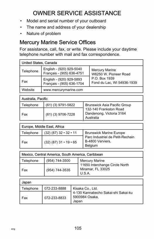
OWNER SERVICE ASSISTANCE
eng 105
• Model and serial number of your outboard• The name and address of your dealership• Nature of problem
Mercury Marine Service OfficesFor assistance, call, fax, or write. Please include your daytimetelephone number with mail and fax correspondence.
United States, Canada
Telephone English ‑ (920) 929‑5040Français ‑ (905) 636‑4751
Mercury MarineW6250 W. Pioneer RoadP.O. Box 1939Fond du Lac, WI 54936-1939Fax English ‑ (920) 929‑5893
Français ‑ (905) 636‑1704Website www.mercurymarine.com
Australia, PacificTelephone (61) (3) 9791‑5822 Brunswick Asia Pacific Group
132-140 Frankston RoadDandenong, Victoria 3164Australia
Fax (61) (3) 9706‑7228
Europe, Middle East, AfricaTelephone (32) (87) 32 • 32 • 11 Brunswick Marine Europe
Parc Industriel de Petit-RechainB-4800 Verviers,Belgium
Fax (32) (87) 31 • 19 • 65
Mexico, Central America, South America, CaribbeanTelephone (954) 744‑3500 Mercury Marine
11650 Interchange Circle NorthMiramar, FL 33025U.S.A.
Fax (954) 744‑3535
JapanTelephone 072‑233‑8888 Kisaka Co., Ltd.
4-130 Kannabecho Sakai-shi Sakai-ku5900984 Osaka,Japan
Fax 072‑233‑8833
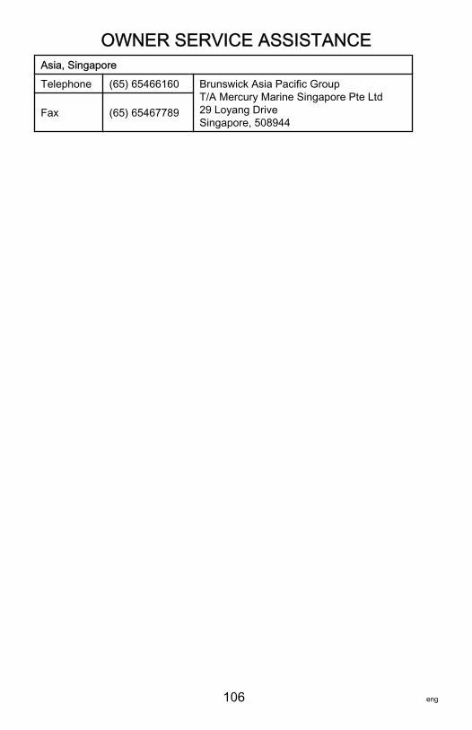
OWNER SERVICE ASSISTANCE
106 eng
Asia, SingaporeTelephone (65) 65466160 Brunswick Asia Pacific Group
T/A Mercury Marine Singapore Pte Ltd29 Loyang DriveSingapore, 508944
Fax (65) 65467789
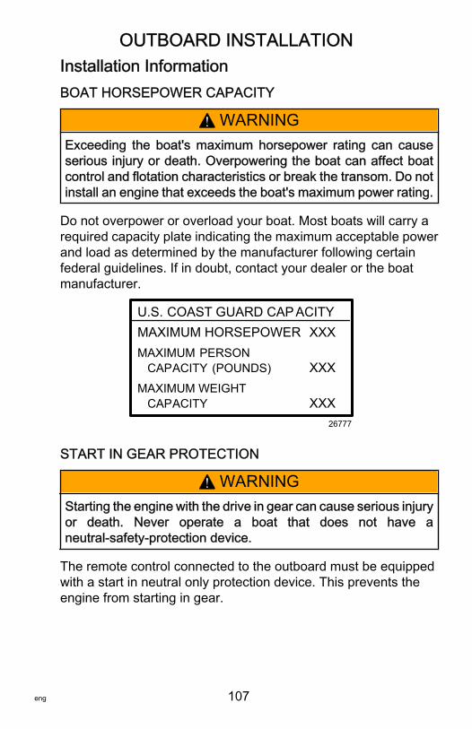
OUTBOARD INSTALLATION
eng 107
Installation InformationBOAT HORSEPOWER CAPACITY
! WARNINGExceeding the boat's maximum horsepower rating can causeserious injury or death. Overpowering the boat can affect boatcontrol and flotation characteristics or break the transom. Do notinstall an engine that exceeds the boat's maximum power rating.
Do not overpower or overload your boat. Most boats will carry arequired capacity plate indicating the maximum acceptable powerand load as determined by the manufacturer following certainfederal guidelines. If in doubt, contact your dealer or the boatmanufacturer.
U.S. COAST GUARD CAP ACITYMAXIMUM HORSEPOWER XXXMAXIMUM PERSON CAPACITY (POUNDS) XXXMAXIMUM WEIGHT CAPACITY XXX
26777
START IN GEAR PROTECTION
! WARNINGStarting the engine with the drive in gear can cause serious injuryor death. Never operate a boat that does not have aneutral‑safety‑protection device.
The remote control connected to the outboard must be equippedwith a start in neutral only protection device. This prevents theengine from starting in gear.
OUTBOARD INSTALLATION
108 eng
SELECTING ACCESSORIES FOR YOUR OUTBOARDGenuine Mercury Precision or Quicksilver Accessories have beenspecifically designed and tested for your outboard. Theseaccessories are available from Mercury Marine dealers.IMPORTANT: Check with your dealer before installingaccessories. The misuse of approved accessories or the use ofnonapproved accessories can damage the product.Some accessories not manufactured or sold by Mercury Marineare not designed to be safely used with your outboard or outboardoperating system. Acquire and read the installation, operation andmaintenance manuals for all your selected accessories.
LOW PERMEATION FUEL HOSE REQUIREMENTRequired for outboards manufactured for sale, sold, or offered forsale in the United States.• The Environmental Protection Agency (EPA) requires that any
outboard manufactured after January 1, 2009 must use lowpermeation fuel hose for the primary fuel hose connecting thefuel tank to the outboard.
• Low permeation hose is USCG Type B1‑15 or Type A1‑15,defined as not exceeding 15/gm²/24 h with CE 10 fuel at 23 °Cas specified in SAE J 1527 ‑ marine fuel hose.
ELECTRIC FUEL PUMPIf an electric fuel pump is used, the fuel pressure must not exceed27.58 kPa (4 psi) at the engine. If necessary, install a pressureregulator to regulate the pressure.
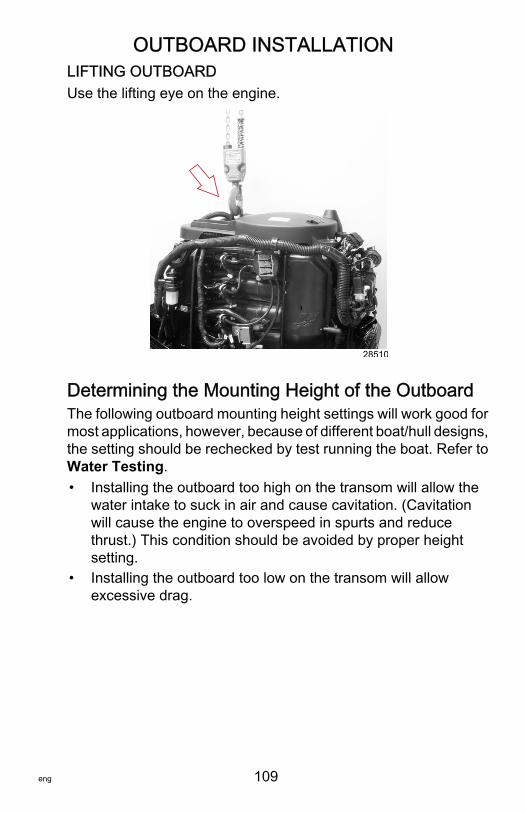
OUTBOARD INSTALLATION
eng 109
LIFTING OUTBOARDUse the lifting eye on the engine.
28510
Determining the Mounting Height of the OutboardThe following outboard mounting height settings will work good formost applications, however, because of different boat/hull designs,the setting should be rechecked by test running the boat. Refer toWater Testing.• Installing the outboard too high on the transom will allow the
water intake to suck in air and cause cavitation. (Cavitationwill cause the engine to overspeed in spurts and reducethrust.) This condition should be avoided by proper heightsetting.
• Installing the outboard too low on the transom will allowexcessive drag.
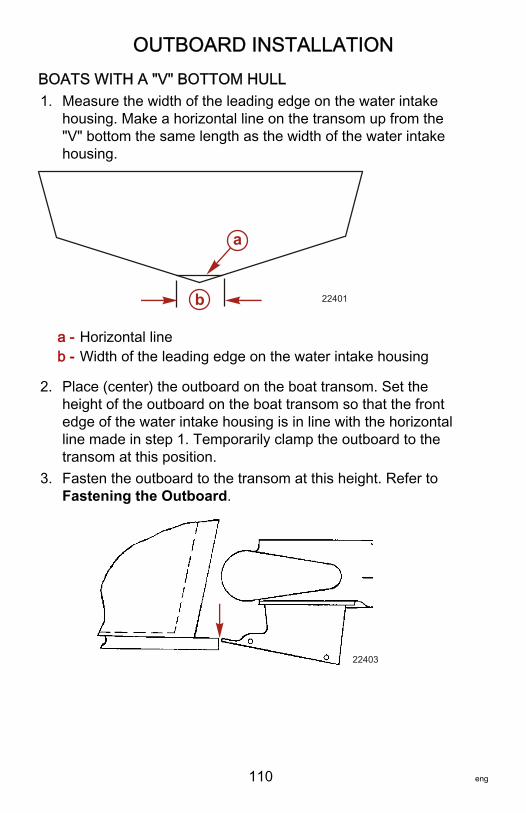
OUTBOARD INSTALLATION
110 eng
BOATS WITH A "V" BOTTOM HULL1. Measure the width of the leading edge on the water intake
housing. Make a horizontal line on the transom up from the"V" bottom the same length as the width of the water intakehousing.
a - Horizontal lineb - Width of the leading edge on the water intake housing
2. Place (center) the outboard on the boat transom. Set theheight of the outboard on the boat transom so that the frontedge of the water intake housing is in line with the horizontalline made in step 1. Temporarily clamp the outboard to thetransom at this position.
3. Fasten the outboard to the transom at this height. Refer toFastening the Outboard.
22403
a
b 22401

OUTBOARD INSTALLATION
eng 111
BOATS WITH A FLAT BOTTOM HULL1. Place (center) the outboard on the boat transom. Set the
height of the outboard on the boat transom so that the frontedge of the water intake housing is in line with the bottom ofthe boat as shown. Temporarily clamp the outboard to thetransom at this position.
2. Fasten outboard to the transom at this height. Refer toFastening the Outboard.
22403
Checking Boat Transom ConstructionIMPORTANT: Determine the strength of the boat transom. Theoutboard mounting locknuts and bolts should be able to hold75 Nm (55 lb‑ft) of torque without the boat transom yielding orcracking. If the boat transom yields or cracks under this torque, theconstruction of the transom may not be adequate. The boattransom must be strengthened or the load carrying area increased.
a - Transom yielding under bolt torqueb - Transom cracking under bolt torque
18961
ab
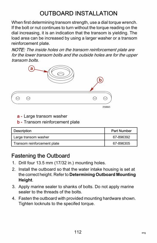
OUTBOARD INSTALLATION
112 eng
When first determining transom strength, use a dial torque wrench.If the bolt or nut continues to turn without the torque reading on thedial increasing, it is an indication that the transom is yielding. Theload area can be increased by using a larger washer or a transomreinforcement plate.NOTE: The inside holes on the transom reinforcement plate arefor the lower transom bolts and the outside holes are for the uppertransom bolts.
a - Large transom washerb - Transom reinforcement plate
Description Part NumberLarge transom washer 67‑896392Transom reinforcement plate 67‑896305
Fastening the Outboard1. Drill four 13.5 mm (17/32 in.) mounting holes.2. Install the outboard so that the water intake housing is set at
the correct height. Refer to Determining Outboard MountingHeight.
3. Apply marine sealer to shanks of bolts. Do not apply marinesealer to the threads of the bolts.
4. Fasten the outboard with provided mounting hardware shown.Tighten locknuts to the specifed torque.
a
b
20860
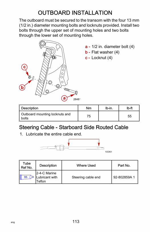
OUTBOARD INSTALLATION
eng 113
The outboard must be secured to the transom with the four 13 mm(1/2 in.) diameter mounting bolts and locknuts provided. Install twobolts through the upper set of mounting holes and two boltsthrough the lower set of mounting holes.
a - 1/2 in. diameter bolt (4)b - Flat washer (4)c - Locknut (4)
Description Nm lb‑in. lb‑ftOutboard mounting locknuts andbolts 75 55
Steering Cable ‑ Starboard Side Routed Cable1. Lubricate the entire cable end.
10261
TubeRef No. Description Where Used Part No.
952-4-C MarineLubricant withTeflon
Steering cable end 92-802859A 1
28481
b
c
a
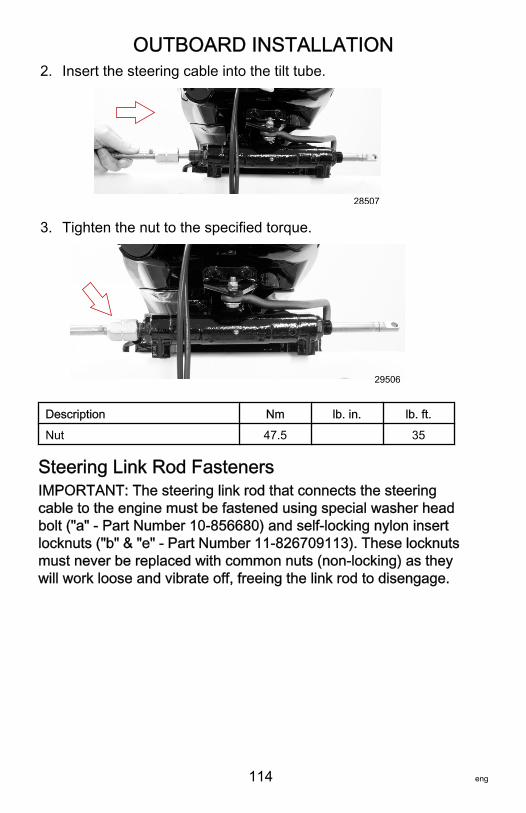
OUTBOARD INSTALLATION
114 eng
2. Insert the steering cable into the tilt tube.
28507
3. Tighten the nut to the specified torque.
29506
Description Nm lb. in. lb. ft.Nut 47.5 35
Steering Link Rod FastenersIMPORTANT: The steering link rod that connects the steeringcable to the engine must be fastened using special washer headbolt ("a" ‑ Part Number 10‑856680) and self‑locking nylon insertlocknuts ("b" & "e" ‑ Part Number 11‑826709113). These locknutsmust never be replaced with common nuts (non‑locking) as theywill work loose and vibrate off, freeing the link rod to disengage.
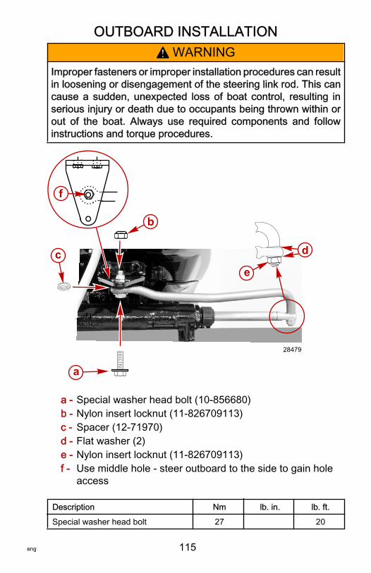
OUTBOARD INSTALLATION
eng 115
! WARNINGImproper fasteners or improper installation procedures can resultin loosening or disengagement of the steering link rod. This cancause a sudden, unexpected loss of boat control, resulting inserious injury or death due to occupants being thrown within orout of the boat. Always use required components and followinstructions and torque procedures.
a - Special washer head bolt (10‑856680)b - Nylon insert locknut (11‑826709113)c - Spacer (12‑71970)d - Flat washer (2)e - Nylon insert locknut (11‑826709113)f - Use middle hole ‑ steer outboard to the side to gain hole
access
Description Nm lb. in. lb. ft.Special washer head bolt 27 20
a
c
b
28479
f
d
e
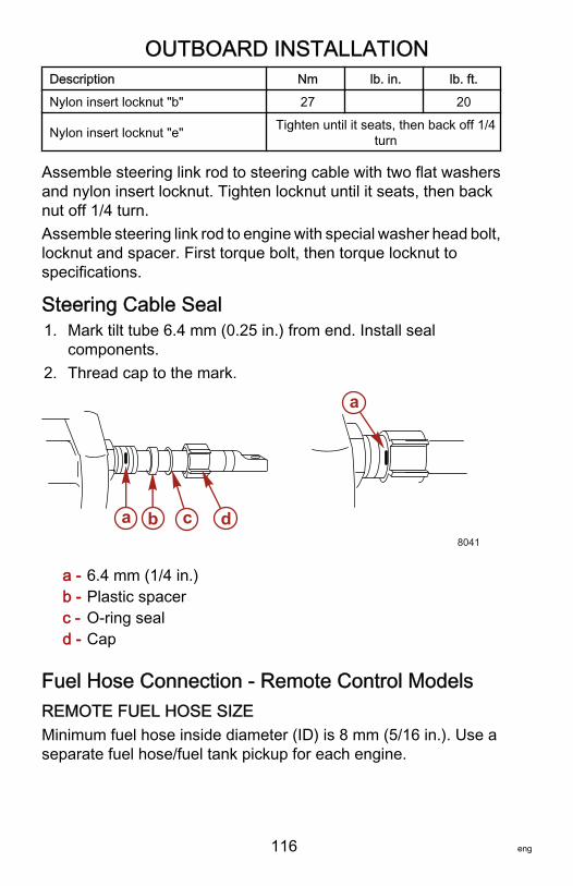
OUTBOARD INSTALLATION
116 eng
Description Nm lb. in. lb. ft.Nylon insert locknut "b" 27 20
Nylon insert locknut "e" Tighten until it seats, then back off 1/4turn
Assemble steering link rod to steering cable with two flat washersand nylon insert locknut. Tighten locknut until it seats, then backnut off 1/4 turn.Assemble steering link rod to engine with special washer head bolt,locknut and spacer. First torque bolt, then torque locknut tospecifications.
Steering Cable Seal1. Mark tilt tube 6.4 mm (0.25 in.) from end. Install seal
components.2. Thread cap to the mark.
a - 6.4 mm (1/4 in.)b - Plastic spacerc - O‑ring seald - Cap
Fuel Hose Connection ‑ Remote Control ModelsREMOTE FUEL HOSE SIZEMinimum fuel hose inside diameter (ID) is 8 mm (5/16 in.). Use aseparate fuel hose/fuel tank pickup for each engine.
a b c d8041
a
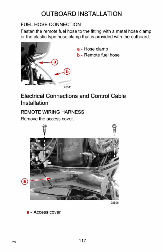
OUTBOARD INSTALLATION
eng 117
FUEL HOSE CONNECTIONFasten the remote fuel hose to the fitting with a metal hose clampor the plastic type hose clamp that is provided with the outboard.
a - Hose clampb - Remote fuel hose
Electrical Connections and Control CableInstallationREMOTE WIRING HARNESSRemove the access cover.
a - Access cover
a
b
28511
a
28696
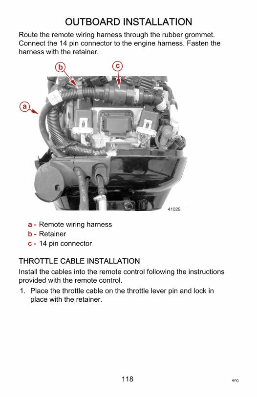
OUTBOARD INSTALLATION
118 eng
Route the remote wiring harness through the rubber grommet.Connect the 14 pin connector to the engine harness. Fasten theharness with the retainer.
a - Remote wiring harnessb - Retainerc - 14 pin connector
THROTTLE CABLE INSTALLATIONInstall the cables into the remote control following the instructionsprovided with the remote control.1. Place the throttle cable on the throttle lever pin and lock in
place with the retainer.
a
b c
41029
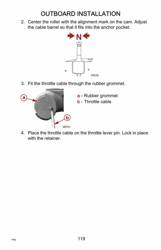
OUTBOARD INSTALLATION
eng 119
2. Center the roller with the alignment mark on the cam. Adjustthe cable barrel so that it fits into the anchor pocket.
N
26838
3. Fit the throttle cable through the rubber grommet.
a - Rubber grommetb - Throttle cable
4. Place the throttle cable on the throttle lever pin. Lock in placewith the retainer.
a
b
28701
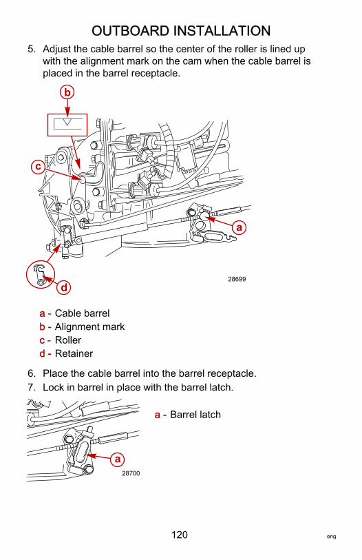
OUTBOARD INSTALLATION
120 eng
5. Adjust the cable barrel so the center of the roller is lined upwith the alignment mark on the cam when the cable barrel isplaced in the barrel receptacle.
a - Cable barrelb - Alignment markc - Rollerd - Retainer
6. Place the cable barrel into the barrel receptacle.7. Lock in barrel in place with the barrel latch.
a - Barrel latch
a
b
c
d28699
28700
a
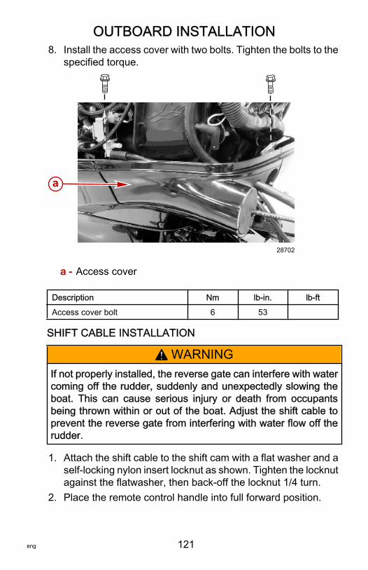
OUTBOARD INSTALLATION
eng 121
8. Install the access cover with two bolts. Tighten the bolts to thespecified torque.
a - Access cover
Description Nm lb‑in. lb‑ftAccess cover bolt 6 53
SHIFT CABLE INSTALLATION
! WARNINGIf not properly installed, the reverse gate can interfere with watercoming off the rudder, suddenly and unexpectedly slowing theboat. This can cause serious injury or death from occupantsbeing thrown within or out of the boat. Adjust the shift cable toprevent the reverse gate from interfering with water flow off therudder.
1. Attach the shift cable to the shift cam with a flat washer and aself‑locking nylon insert locknut as shown. Tighten the locknutagainst the flatwasher, then back‑off the locknut 1/4 turn.
2. Place the remote control handle into full forward position.
a
28702
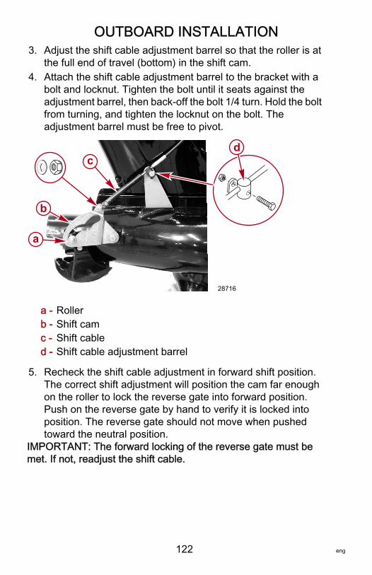
OUTBOARD INSTALLATION
122 eng
3. Adjust the shift cable adjustment barrel so that the roller is atthe full end of travel (bottom) in the shift cam.
4. Attach the shift cable adjustment barrel to the bracket with abolt and locknut. Tighten the bolt until it seats against theadjustment barrel, then back‑off the bolt 1/4 turn. Hold the boltfrom turning, and tighten the locknut on the bolt. Theadjustment barrel must be free to pivot.
a - Rollerb - Shift camc - Shift cabled - Shift cable adjustment barrel
5. Recheck the shift cable adjustment in forward shift position.The correct shift adjustment will position the cam far enoughon the roller to lock the reverse gate into forward position.Push on the reverse gate by hand to verify it is locked intoposition. The reverse gate should not move when pushedtoward the neutral position.
IMPORTANT: The forward locking of the reverse gate must bemet. If not, readjust the shift cable.
a
b
cd
28716
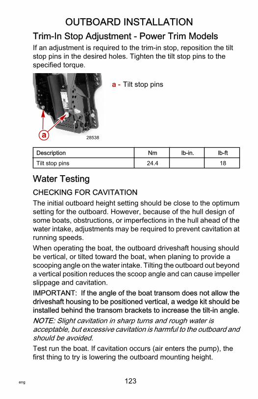
OUTBOARD INSTALLATION
eng 123
Trim‑In Stop Adjustment ‑ Power Trim ModelsIf an adjustment is required to the trim‑in stop, reposition the tiltstop pins in the desired holes. Tighten the tilt stop pins to thespecified torque.
a - Tilt stop pins
Description Nm lb‑in. lb‑ftTilt stop pins 24.4 18
Water TestingCHECKING FOR CAVITATIONThe initial outboard height setting should be close to the optimumsetting for the outboard. However, because of the hull design ofsome boats, obstructions, or imperfections in the hull ahead of thewater intake, adjustments may be required to prevent cavitation atrunning speeds.When operating the boat, the outboard driveshaft housing shouldbe vertical, or tilted toward the boat, when planing to provide ascooping angle on the water intake. Tilting the outboard out beyonda vertical position reduces the scoop angle and can cause impellerslippage and cavitation.IMPORTANT: If the angle of the boat transom does not allow thedriveshaft housing to be positioned vertical, a wedge kit should beinstalled behind the transom brackets to increase the tilt‑in angle.NOTE: Slight cavitation in sharp turns and rough water isacceptable, but excessive cavitation is harmful to the outboard andshould be avoided.Test run the boat. If cavitation occurs (air enters the pump), thefirst thing to try is lowering the outboard mounting height.
a 28538
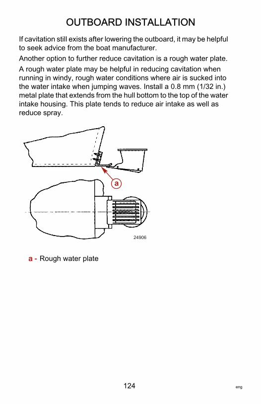
OUTBOARD INSTALLATION
124 eng
If cavitation still exists after lowering the outboard, it may be helpfulto seek advice from the boat manufacturer.Another option to further reduce cavitation is a rough water plate.A rough water plate may be helpful in reducing cavitation whenrunning in windy, rough water conditions where air is sucked intothe water intake when jumping waves. Install a 0.8 mm (1/32 in.)metal plate that extends from the hull bottom to the top of the waterintake housing. This plate tends to reduce air intake as well asreduce spray.
a - Rough water plate
a
24906

MAINTENANCE LOG
eng 125
Maintenance LogRecord all maintenance performed on your outboard here. Be sureto save all work orders and receipts.
Date Maintenance Performed Engine Hours