40 x 180 frame tent installation instructions
TRANSCRIPT

40’ x 180’ Classic Series Frame Tent www.GetTent.com / www.CelinaTent.com PG.1© 2013 Celina Tent Inc.
40’ x 180’ CLASSIC SERIES FRAMETENT SECTIONAL PRODUCT MANUAL
Read this manual before using this product. Failure to do so can result in serious injury. SAVE THIS MANUAL
The warnings, cautions, and instructions discussed in this instruction manual cannot cover all possible conditions and situations that may occur. It must be understood by the user that common sense and caution are factors which cannot be built into this product, but must be supplied by the installer and/or user.
Tent, canopy, structure, and shelter products are manufactured for use as temporary structures and do not meet structural code unless specified. Since weather is unpredictable, the installer/end user must incorporate their own good judgment, common sense and knowledge of local conditions with the installation instruction guide-lines. The installer is responsible for anticipating weather severity for proper time and method of installation.
This is the safety alert symbol. It is used to alert you to potential personal injury hazards.Obey all safety messages that follow this symbol to avoid possible injury or death. Indicates a hazardous situation which, if not avoided, could result in death or serious injury.Indicates a hazardous situation which, if not avoided, could result in minor or moderate injury.
ver.20140513
NOTICE
WARNING SYMBOLS AND DEFINITIONS
A Division of
SAFETYM
AINTEN
ANCE
INSTALLATIO
NCO
NTACTS
A Division of

40’ x 180’ Classic Series Frame Tent www.GetTent.com / www.CelinaTent.com PG.2© 2013 Celina Tent Inc.
Description40’ x 180’ Classic Series Frame Tent, SectionalThe Classic Series Frame tent is a tent which utilizes a simple frame to support the tent top, maximizing the usable space available underneath the tent. All Classic Series Frame tents use West Coast Style frames and fittings, making them interchangeable with all other frames and fittings in this style. Frame tents need to be staked to the ground or otherwise anchored for maximum stability.
Suggested EquipmentDrop cloth or ground cloth, sledge hammer, or electric / gas breaker hammer fitted with stake driver bit, stake puller, and frame tent jack/ lift.Colors available by special order White & Red (5051)White & Green (5052) White & Blue (5053)
PRODUCT SPECIFICATIONSSAFETY
MAIN
TENAN
CEIN
STALLATION
CON
TACTS
Classic Series Frame Tent SpecificationsWidth 40 ft. / 12.2mLength 180 ft. / 54.9mArea 7200 ft² / 669.8 m²Eave Height 7’ / 2.1m 8’ / 2.4mOverall Height 17’ / 5.2m 18’ / 5.5m
Pitch 10’ / 3.0mComplete Weight Aluminum 4160 Lbs. / 1887 Kg. 4204 Lbs. / 1907 Kg.Complete Weight Alum. Hybrid 5165 Lbs. / 2343 Kg. 5253 Lbs. / 2383 Kg.Series / Brand ClassicClass FrameCenter Pole NoStyle / Shape TraditionalExpandable YesCustom Printing Available YesFabric Material PVC Coated PolyesterFabric Material Weight 16 oz. / yd2 / 540 gsmFabric Translucency BlockoutWater Repellency WaterproofFlame Resistant YesUV Resistant YesMold and Mildew Resistant YesFrame / Pole Material AluminumLongest Component Alum. 21’10.5” / 6.7mPersons required for setup 6-12
Occupancy 720 Sit Down Dinner - 1200 Cathedral Seating

40’ x 180’ Classic Series Frame Tent www.GetTent.com / www.CelinaTent.com PG.3© 2013 Celina Tent Inc.
Site selection is extremely important. The installer must adhere to local building codes and fire regulations. The installer must evaluate each installation site and determine the proper securing and anchoring method and device appropriate for the conditions. Some soils require different staking or securing methods than what may be/have been purchased with the standard tent package. Celina Tent’s instructions, YouTube videos, and Layout Handbook summarize all the functions of each product, the rules for using them and suggestions for their use. However, field situations, site conditions, weather and local experience may mandate other methods. Review the following conditions at the proposed site and plan accordingly. The best site qualities are:• Location: Elevated, level, and clear of debris• Soil Conditions: Adequate for stable anchoring• Space: Adequate space for the perimeter and stake lines• Surface Type: Grass, Gravel, Concrete, Asphalt, Wood• Site Access: Materials and services can easily be delivered to the site Also allow for:• Overhead Obstructions: Electrical/telephone lines, tree branches• Underground Utilities: Electric, Gas, Oil, Steam, Telephone, CATV, Water, Sewer• Weather Effects: Monitor for extreme weather conditions and evacuate if necessary • Emergency Exit Capabilities: Provide evacuation routes in case of a fire or bad weather
SITE SELECTION
STAY ALERT: Watch what you are doing, and use common sense when installing/striking a tent, canopy, structure, or shelter. Do not setup/strike while under the influence of drugs, alcohol, or medication. A moment of inattention may result in serious personal injury.
DO NOT OVER LIFT: The equipment may be heavy and may require 2 or more people to lift and move.
DO NOT OVERREACH: Keep proper footing and balance at all times. Use a ladder when necessary.
DRESS PROPERLY: Do not wear loose clothing or jewelry. Contain long hair. Keep hair, clothing, and hands/gloves away from power equipment and snag or pinch points.
USE SAFETY EQUIPMENT: Eye protection, safety shoes, hard hats, or hearing protection must be used for appropriate conditions.
Since weather is unpredictable, the installer/end user must incorporate their own judgment, common sense and knowledge of local conditions with the installation instruction guidelines. The installer is responsible for antici-pating weather severity for proper time and method of installation.• Rain: Rain water can collect on the tent fabric and cause ‘ponding’ or ‘water pocketing’ under cer-
tain weather conditions, especially if the tent is not installed and tensioned correctly. The additional weight from the water will cause the tent to sag and ponding will continue to get worse. The weight can destroy the tent fabric and/or cause the poles and baseplates to sink into the soil. Highly saturated soil will cause the stakes to lose their holding power.
• Wind: Wind or wind and rain can cause the tension of the tent to change by loosening ratchet assemblies, pulling stakes, and or causing the poles to shift or sink. It is very important to do routine main-tenance checks and maintain proper tension on the tent top at all times especially if weather conditions are such that ratchets are beginning to loosen.
• Lightning: Immediately evacuate the tent until the chance of a lightning strike is no longer present.• Snow: Tents, canopies, structures, and shelters are not designed to carry any type of snow loading. These
products should not be used if snow of any kind is present, and must be evacuated immediately.
PERSONAL SAFETY
WEATHER
SAFETYM
AINTEN
ANCE
INSTALLATIO
NCO
NTACTS
40’ x 180’ Classic Series Frame Tent www.GetTent.com / www.CelinaTent.com PG.4© 2013 Celina Tent Inc.
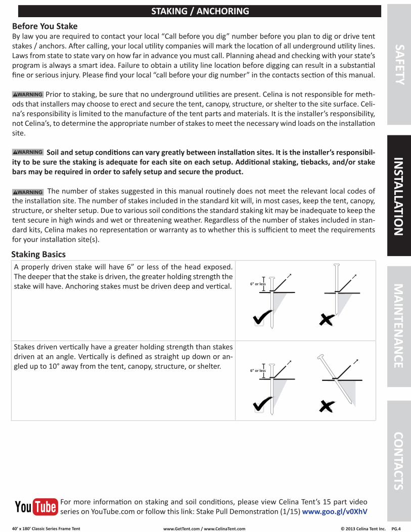
A properly driven stake will have 6” or less of the head exposed. The deeper that the stake is driven, the greater holding strength the stake will have. Anchoring stakes must be driven deep and vertical.
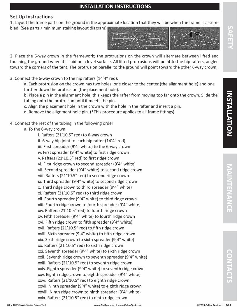
Stakes driven vertically have a greater holding strength than stakes driven at an angle. Vertically is defined as straight up down or an-gled up to 10° away from the tent, canopy, structure, or shelter.
Before You StakeBy law you are required to contact your local “Call before you dig” number before you plan to dig or drive tent stakes / anchors. After calling, your local utility companies will mark the location of all underground utility lines. Laws from state to state vary on how far in advance you must call. Planning ahead and checking with your state’s program is always a smart idea. Failure to obtain a utility line location before digging can result in a substantial fine or serious injury. Please find your local “call before your dig number” in the contacts section of this manual.
Prior to staking, be sure that no underground utilities are present. Celina is not responsible for meth-ods that installers may choose to erect and secure the tent, canopy, structure, or shelter to the site surface. Celi-na’s responsibility is limited to the manufacture of the tent parts and materials. It is the installer’s responsibility, not Celina’s, to determine the appropriate number of stakes to meet the necessary wind loads on the installation site.
Soil and setup conditions can vary greatly between installation sites. It is the installer’s responsibil-ity to be sure the staking is adequate for each site on each setup. Additional staking, tiebacks, and/or stake bars may be required in order to safely setup and secure the product.
The number of stakes suggested in this manual routinely does not meet the relevant local codes of the installation site. The number of stakes included in the standard kit will, in most cases, keep the tent, canopy, structure, or shelter setup. Due to various soil conditions the standard staking kit may be inadequate to keep the tent secure in high winds and wet or threatening weather. Regardless of the number of stakes included in stan-dard kits, Celina makes no representation or warranty as to whether this is sufficient to meet the requirements for your installation site(s).
Staking Basics
STAKING / ANCHORINGSAFETY
MAIN
TENAN
CEIN
STALLATION
CON
TACTS
For more information on staking and soil conditions, please view Celina Tent’s 15 part video series on YouTube.com or follow this link: Stake Pull Demonstration (1/15) www.goo.gl/v0XhV
6” or less
6” or less

40’ x 180’ Classic Series Frame Tent www.GetTent.com / www.CelinaTent.com PG.5© 2013 Celina Tent Inc.
40’ x 180’ Classic Series Frame Tent, SectionalDescription (Key) Size/ Color Qty. PictureRafter 21’10.5” / Red 32Hip Rafter 14’4” / Red 16Corner Rafter 10’6” / Green 8Spreader 9’4”/ White 58
Legs 6’8”(7’8”) / Brown(Black)
44
Rafter Bar 14’4’ / Red 13Corner 4
Top ViewSide View
Side Tee w/ Ring 34
6 Way Crown 2
Base Plates 44
R Pin OR Pin & Bail 386
6 Way Side Tee w/ Ring 6
6 Way Hip Joint 4
Ridge Crown 13
Ridge Support Bracket 26
A. Ratchet Buckle with Loop Strap
2” Ratchet5’ Loop
44
B. Loop Strap 8’ Loop 44Single Head Stakes 42” 44
Cable 40’ 15NOTE: When the Ratchet Buckle with Loop Strap A is connected to Loop Strap B it forms the Ratchet Assembly.
Tent Top 40’x180’ 9 pc.
Tent Bag C 9
REQUIRED HARDWARESAFETY
MAIN
TENAN
CEIN
STALLATION
CON
TACTS
Round Bottom Tent Bag Wrap Around Tent Bag
OR
Top ViewSide View
OR
Side View Top View

40’ x 180’ Classic Series Frame Tent www.GetTent.com / www.CelinaTent.com PG.6© 2013 Celina Tent Inc.
SAFETYM
AINTEN
ANCE
INSTALLATIO
NCO
NTACTS
PARTS / MINIMUM STAKING LAYOUT
Ratchet Assembly
B
A
OPTIONAL ACCESSORIESSidewall(s) 20’ 4Sidewall(s) 30’ 12
40’ x 180’ (9 PC) Classic Frame
Frame TubingDescription Size Color Qty.Rafter 21’10.5” Red 32Hip Rafter 14’4” Red 16Corner Rafter 10’6” Green 8Spreader 9’4” White 58Legs 6’8”(7’8”) Brown (Black) 44Rafter Bar 14’4” Red 13
Frame FittingsDescription Qty.Corner 4Side Tee w/ Ring 346 Way Crown 2Base Plates 44R Pin (Pin & Bail) 3866 Way Side Tee w/ Ring
6
6 Way Hip Joint 4Ridge Crown 13Ridge SupportBracket
26
40’ Cable 15Ratchet Buckles 44Stake / Anchors 44
SidewallsSize Qty.20’ 430’ 12
40’ Wide Frame Tent Standard Pitch = 10’
40’ Cables w/ Carabiners
CornerF01COR
Ridge CrownF08RC
Hip Rafter
Rafter
6 Way CrownF056WC
6 Way Side Teew/ Ring
F116WSTRING
A
B
Single Head Stakes
Base Plate
Legs
Spreader
Rafter
CornerRafter
6 Way Hip JointF106WHJ Hip
Rafter
Ridge Support Bracket
F12RSB Rafter Bar
Spreader
Side Teew/ Ring
F02STRING
180’
40’
5’
40’ x 180’ Classic Series Frame Tent www.GetTent.com / www.CelinaTent.com PG.7© 2013 Celina Tent Inc.
Set Up Instructions1. Layout the frame parts on the ground in the approximate location that they will be when the frame is assem-bled. (See parts / minimum staking layout diagram)
2. Place the 6-way crown in the framework; the protrusions on the crown will alternate between lifted and touching the ground when it is laid on a level surface. All lifted protrusions will point to the hip rafters, angled toward the corners of the tent. The protrusion parallel to the ground will point toward the other 6-way crown.
3. Connect the 6-way crown to the hip rafters (14’4” red): a. Each protrusion on the crown has two holes; one closer to the center (the alignment hole) and one further down the protrusion (the placement hole). b. Place a pin in the alignment hole; this keeps the rafter from moving too far onto the crown. Slide the tubing onto the protrusion until it meets the pin. c. Align the placement hole in the crown with the hole in the rafter and insert a pin. d. Remove the alignment hole pin. (*This procedure applies to all frame fittings)
4. Connect the rest of the tubing in the following order: a. To the 6-way crown: i. Rafters (21’10.5” red) to 6-way crown ii. 6-way hip joint to each hip rafter (14’4” red) iii. First spreader (9’4” white) to the 6-way crown iv. First spreader (9’4” white) to first ridge crown v. Rafters (21’10.5” red) to first ridge crown vi. First ridge crown to second spreader (9’4” white) vii. Second spreader (9’4” white) to second ridge crown viii. Rafters (21’10.5” red) to second ridge crown ix. Third spreader (9’4” white) to second ridge crown x. Third ridge crown to third spreader (9’4” white) xi. Rafters (21’10.5” red) to third ridge crown xii. Fourth spreader (9’4” white) to third ridge crown xiii. Fourth ridge crown to fourth spreader (9’4” white) xiv. Rafters (21’10.5” red) to fourth ridge crown xv. Fifth spreader (9’4” white) to fourth ridge crown xvi. Fifth ridge crown to fifth spreader (9’4” white) xvii. Rafters (21’10.5” red) to fifth ridge crown xviii. Sixth spreader (9’4” white) to fifth ridge crown xix. Sixth ridge crown to sixth spreader (9’4” white) xx. Rafters (21’10.5” red) to sixth ridge crown xxi. Seventh spreader (9’4” white) to sixth ridge crown xxii. Seventh ridge crown to seventh spreader (9’4” white) xxiii. Rafters (21’10.5” red) to seventh ridge crown xxiv. Eighth spreader (9’4” white) to seventh ridge crown xxv. Eighth ridge crown to eighth spreader (9’4” white) xxvi. Rafters (21’10.5” red) to eighth ridge crown xxvii. Ninth spreader (9’4” white) to eighth ridge crown xxviii. Ninth ridge crown to ninth spreader (9’4” white) xxix. Rafters (21’10.5” red) to ninth ridge crown
SAFETYM
AINTEN
ANCE
INSTALLATIO
NCO
NTACTS
INSTALLATION INSTRUCTIONS

40’ x 180’ Classic Series Frame Tent www.GetTent.com / www.CelinaTent.com PG.8© 2013 Celina Tent Inc.
SAFETYM
AINTEN
ANCE
INSTALLATIO
NCO
NTACTS
INSTALLATION INSTRUCTIONS
7. Fasten the loop strap (B) to the fitting at each leg location.
5. Clip one carabiner on the 40’ cable to the O ring on the 6 way side tee. Pull the cable across the 40’ width and connect the other end of the cable to the 6 way side tee on the adjacent side by clipping the other carabiner to the O ring on the fitting. Repeat at corresponding 6 way side tee location.
6. Clip one carabiner on the 40’ cable to the O ring on the side tee. Pull the cable across the 40’ width and con-nect the other end of the cable to the side tee on the adjacent side by clipping the other carabiner to the O ring on the fitting. Repeat at all corresponding side tee locations in between the 6 way side tees.
xxx. Tenth spreader (9’4” white) to ninth ridge crown xxxi. Tenth ridge crown to tenth spreader (9’4” white) xxxii. Rafters (21’10.5” red) to tenth ridge crown xxxiii. Eleventh spreader (9’4” white) to tenth ridge crown xxxiv. Eleventh ridge crown to eleventh spreader (9’4” white) xxxv. Rafters (21’10.5” red) to eleventh ridge crown xxxvi. Twelfth spreader (9’4” white) to eleventh ridge crown xxxvii. Twelfth ridge crown to twelfth spreader (9’4” white) xxxviii. Rafters (21’10.5” red) to twelfth ridge crown xxxix. Thirteenth spreader (9’4” white) to twelfth ridge crown xl. Thirteenth ridge crown to thirteenth spreader (9’4” white) xli. Rafters (21’10.5” red) to thirteenth ridge crown * Slide the ridge support brackets onto the middle rafters (26 x 21’10.5”), one ridge support bracket per rafter. Connect the ridge support brackets with a (14’4” red) rafter bar and pin. Level and tighten. xlii. Fourteenth spreader (9’4” white) to thirteenth ridge crown xliii. Fourteenth spreader (9’4” white) to second 6-way crown; repeat rafter/hip rafter steps b. To each 6-way hip joint: i. Hip rafters (14’4” red) to the first, third, and fifth protrusions ii. Corner rafters (10’6” green) to the second and fourth protrusions c. 6-way side tee fitting to rafters (21’10.5” red) d. Hip rafters (14’4” red) to each 6-way side tee fitting e. Side tee fittings to corner rafters (10’6” green) f. Side tee fittings to rafters (21’10.5” red) g. Corner fittings to hip rafters (14’4” red) h. Spreaders (9’4” white) to 6-way side tee fittings i. Spreaders (9’4” white) to side tee fittings j. Spreaders (9’4” white) to corner fittings
40’ x 180’ Classic Series Frame Tent www.GetTent.com / www.CelinaTent.com PG.9© 2013 Celina Tent Inc.
9. Lace the tent together: a. Line up each tent section (the lace end will always be on the bottom) so that they overlap. b. Starting in the middle and working toward the edge pull the first lace up through the first small grommet. Pull the second lace up through the second grommet, then through the loop of the first lace. c. While lacing the tent, be sure to connect the rain flap to the rope covering the lace line. This eliminates the need to crawl on the tent after it has been laced. d. Continue in this fashion until the third grommet from the edge of the tent is reached. The third lace should be twice as long as the other loops (this is referred to as a double loop). e. Pull the final two lines through the grommets and loop the second lace from the tent perimeter into the first lace (the lace is now going towards the direction of the double loop). Pull the third lace (double loop) through the second loop. The third lace (double loop) should now be strung through 2 loops (the second loop and the fourth loop). f. Tie off just past the third grommet; this secures the entire lace line. g. Connect the hook and loop located on the valance section at the end of each lace line. h. Repeat this method to secure all other lace lines.
SAFETYM
AINTEN
ANCE
INSTALLATIO
NCO
NTACTS
INSTALLATION INSTRUCTIONS
12. Attach the base plates to the legs (6’8” brown, or 7’8” black), securing with a pin.
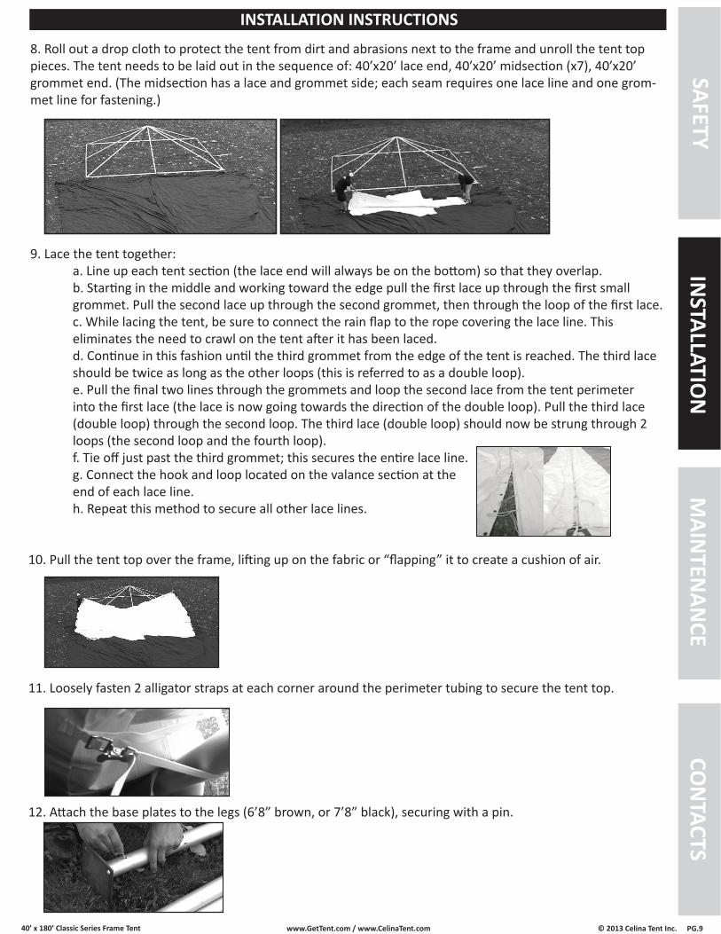
8. Roll out a drop cloth to protect the tent from dirt and abrasions next to the frame and unroll the tent top pieces. The tent needs to be laid out in the sequence of: 40’x20’ lace end, 40’x20’ midsection (x7), 40’x20’ grommet end. (The midsection has a lace and grommet side; each seam requires one lace line and one grom-met line for fastening.)
11. Loosely fasten 2 alligator straps at each corner around the perimeter tubing to secure the tent top.
10. Pull the tent top over the frame, lifting up on the fabric or “flapping” it to create a cushion of air.
40’ x 180’ Classic Series Frame Tent www.GetTent.com / www.CelinaTent.com PG.10© 2013 Celina Tent Inc.
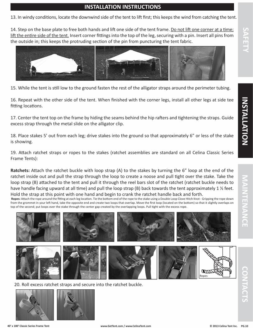
14. Step on the base plate to free both hands and lift one side of the tent frame. Do not lift one corner at a time; lift the entire side of the tent. Insert corner fittings into the top of the leg, securing with a pin. Insert all pins from the outside in; this keeps the protruding section of the pin from puncturing the tent fabric.
19. Attach ratchet straps or ropes to the stakes (ratchet assemblies are standard on all Celina Classic Series Frame Tents):
Ratchets: Attach the ratchet buckle with loop strap (A) to the stakes by turning the 6” loop at the end of the ratchet inside out and pull the strap through the loop to create a noose and pull tight over the stake. Take the loop strap (B) attached to the tent and pull it through the reel bars slot of the ratchet (ratchet buckle needs to have handle facing upward at all time) and pull the loop strap (B) back towards the tent approximately 1 ½ feet. Hold the strap at this point with one hand and begin to crank the ratchet handle back and forth. Ropes: Attach the rope around the fitting at each leg location. Tie the bottom end of the rope to the stake using a Double Loop Clove Hitch Knot - Gripping the rope down from the grommet in your left hand, take the opposite end and create two loops that overlap. Move the first loop (located on the bottom) so that it slightly overlaps on top of the second; put loops over the stake through the center gap created by the overlapping loops. Pull tight with the excess rope.
Ropes
20. Roll excess ratchet straps and secure into the ratchet buckle.
SAFETYM
AINTEN
ANCE
INSTALLATIO
NCO
NTACTS
INSTALLATION INSTRUCTIONS
13. In windy conditions, locate the downwind side of the tent to lift first; this keeps the wind from catching the tent.
15. While the tent is still low to the ground fasten the rest of the alligator straps around the perimeter tubing.
16. Repeat with the other side of the tent. When finished with the corner legs, install all other legs at side tee fitting locations.
17. Center the tent top on the frame by hiding the seams behind the hip rafters and tightening the straps. Guide excess strap through the metal slide on the alligator clip.
18. Place stakes 5’ out from each leg; drive stakes into the ground so that approximately 6” or less of the stake is showing.

40’ x 180’ Classic Series Frame Tent www.GetTent.com / www.CelinaTent.com PG.11© 2013 Celina Tent Inc.
21. The tent top should now be complete. If sidewalls are desired, unroll the sidewalls between the stakes and the legs around the perimeter of the tent. Starting at a leg, clip the sidewall snap hooks to the rope line that is attached to the tent top.
Sidewall Rope Tensioning: For new tents and during its life cycle, it may be necessary to tighten the sidewall support rope that runs the perimeter of the tent top. After the tent has been set up and tensioned, locate the corner where the sidewall rope starts and stops. Securely tie off one end of the rope. While pulling against the tie-off point, work your way around the perimeter of the tent, pulling out any unnecessary rope slack. Tie off the opposite end of the rope once reached.
SAFETYM
AINTEN
ANCE
INSTALLATIO
NCO
NTACTS
INSTALLATION INSTRUCTIONS
40’ x 180’ Classic Series Frame Tent www.GetTent.com / www.CelinaTent.com PG.12© 2013 Celina Tent Inc.
SAFETYM
AINTEN
ANCE
INSTALLATIO
NCO
NTACTS
INSTALLATION INSTRUCTIONS
Striking Instructions1. Loosen all ratchet strap assemblies.
2. Remove the side legs.
3. Unfasten all anchoring devices and alligator straps from the perimeter tubing (with the exception of 2 at each corner).
4. Remove 2 corner legs from one side and carefully set the tent frame on the ground.
5. Repeat with opposite side.
6. Unfasten the rest of the straps, completely disconnecting the tent top from the frame and stakes.
7. Roll out a drop cloth next to the frame.
8. Carefully remove the tent top from the frame, lifting up on the fabric or “flapping” it to create a cushion of air.
9. Unlace the tent top: a. Separate the valance hook and loop that connects the tents together. Unclip the rain flap until the lace line tie-off is accessed. b. Untie knot and unlace the tent top section while disconnecting the rain flap.
10. Fold and roll the tent top pieces as tight as possible. Remember not to stand or walk on the tent top fabric.
11. Bagging (always use a drop cloth to protect the tent top from dirt and abrasions while bagging): a. For Wrap-Around Tent Bag: i. Lay the bag next to the tent top with the side-release buckles facing down. Roll the tent top onto the center of the bag. ii. Connect the two short male and female side-release buckles; pull tight. iii. Connect the remaining side-release buckle and pull tight. b. For Round-Bottom Bag: i. Place the folded tent top into the upright vertical position. ii. Pull the round bottom tent bag over the upright tent top. iii. Turn the tent top and bag over, pull the draw string tight and tie off.12. Fold and roll up the drop cloth.
13. Disassemble all of the corner, side tee, and center crown fittings by removing the pins and sliding the tubing off of the fittings. Work from the perimeter of the frame inward.
14. Remove all stakes.
40’ x 180’ Classic Series Frame Tent www.GetTent.com / www.CelinaTent.com PG.13© 2013 Celina Tent Inc.
For maximum life of Celina fabrics, Celina recommends regular cleaning with the use of a soft brush with neu-tral soaps or cleaners, such as Celina Cleaning Products, Ivory dish soap, or warm water. Thorough rinsing and drying is required before storing the fabric.
Things that will cause premature degradation and may reduce life expectancy of a tent:• Improper handling during installation/dismantling on rough surfaces will create pinholes and abrasions.
ALWAYS USE A DROP CLOTH/GROUND CLOTH DURING INSTALLATION AND DISMANTLING.• Walking on the fabric during installation/dismantling will create pinholes and abrasions.• Extended use of the tent without cleaning• Accumulation of dirt on the vinyl surface will promote the growth of mold and mildew and premature wear. • Storage of vinyl that has not been dried thoroughly. Even a slightly damp product can promote the growth
of mildew when folded and stored. Mold and mildew may require harsh cleaners to remove, which may cause premature wear. The best solution is to take every precaution to keep mold and mildew from growing in the first place. NEVER STORE A TENT, CANOPY, STRUCTURE, OR SHELTER IN A WET OR DAMP CONDITION.
• Harsh detergents and cleaners, which contain a solvent or bleach. The longer the exposure of PVC vinyl to these products, the more it will reduce the life of the PVC vinyl.
• High-abrasive cleaners, including wire brushes, power wasters and/or commercial washing machines will result in premature wear and deterioration of tent fabrics.
• Wind whip – Loosely tensioned fabric that whips in the wind will damage over time.
Vinyl RepairCelina’s repair products provide an easy solution to tears, punctures, or holes. Repair kits and tools are avail-able online at www.GetTent.com or by contacting Celina.
Celina Tent Inc. warrants that this product will be free from defects in material and workmanship for a period of one (1) year following the date of purchase. Defects are limited to any defect which is a result of the manufac-turing process. Excluded are holes, punctures, or other damages which can be caused during normal installation of a tent whenever proper procedures are not followed. Celina at its option will repair or replace this product or any component of product found to be defective during this warranty period. This warranty is valid for the origi-nal purchaser only, and is not transferable. This warranty does not cover normal wear or damage resulting from negligent use or misuse of the product, use contrary to instructions, repairs or alterations by anyone other than Celina, or forces of nature. Celina Tent is not responsible for methods that installers may choose to erect and se-cure the tent to the ground. Celina’s responsibility is limited to the manufacture of the tent parts and materials.
This warranty is in lieu of all other warranties, and there are no warranties, expressed or implied, including war-ranties of merchantability of fitness for a particular purpose, which extend beyond the description on the face hereof. Celina Tent Inc. shall not be liable for any incidental or consequential damages. Some jurisdictions do not allow the exclusion of implied warranties or the imitation on incidental or consequential damages, so the above exclusions and limitations may not apply to you.
Celina fabrics are inherently flame resistant. Open flames should never be used under any tent, canopy, structure, or shelter. Fabrics meet or exceed one or more of the following flammability specifications:
NFPA-701 CPAI-84 ASTM D 6413BS 5438 BS 7837 (1996) DIN 4102-B1
TENT CARE
PRODUCT WARRANTY
FLAME RESISTANCESAFETY
MAIN
TENAN
CEIN
STALLATION
CON
TACTS

40’ x 180’ Classic Series Frame Tent www.GetTent.com / www.CelinaTent.com PG.14© 2013 Celina Tent Inc.
STATE CENTER PHONEAlabama Alabama Line Location 800/292-8525
Alaska Locate Call Center of Alaska 800/478-3121
Arizona Arizona Blue Stake 800/782-5348
Arkansas Arkansas One Call System 800/482-8998
California Underground Service Alert 800/227-2600
Colorado Utility Notification Center of Colorado 800/922-1987
Connecticut Call Before You Dig 800/922-4455
Delaware Miss Utility of Delaware 800/282-8555
Florida Call Sunshine 800/432-4770
Georgia Utilities Protection Center 800/282-7411
Hawaii Underground Service Alert North 800/227-2600
Underground Service Alert South 800/227-2600
Idaho Palouse Empire Underground 800/822-1974
Utilities Underground Location Center 800/424-5555
Dig Line 800/342-1585
One Call Concepts - Idaho 800/626-4950
Shoshone County One Call 800/398-3285
Illinois Chicago Utility Alert Network 800/892-0123
Indiana Indiana Underground Plant Protection 800/382-5544
Iowa Underground Plant Location Service 800/292-8989
Kansas Kansas One-Call Center 800/344-7233
Kentucky Kentucky Underground Protection 800/752-6007
Louisiana Louisiana One Call System 800/272-3020
Maine Dig Safe - Maine 888/344-7233
Maryland
Miss Utility 800/257-7777
Miss Utility of DESMARVA 800/282-8555
Massachusetts Dig Safe-Massachusetts 888/344-7233
Michigan Miss Dig System 800/482-7171
Minnesota Gopher State One Call 800/252-1166
Mississippi Mississippi One Call System 800/277-6477
Missouri Missouri One Call System 800/344-7483
Montana
Utilities Underground Location Center 800/424-5555
Montana U-Dig 800/551-8344
Nebraska Diggers Hotline 800/331-5666
Nevada Underground Service Alert North 800/227-2600
New Hampshire Dig Safe-New Hampshire 888/344-7233
New Jersey Garden State Underground 800/272-1000
New Mexico
New Mexico One Call System 800/321-2537
Las Cruces-Dona Ana Utility Council 888/526-0400
STATE CENTER PHONENew York Dig Safely New York 800/926-7962
New York City-Long Island One Call 800/272-4480
North Carolina North Carolina One Call 800/634-4949
North Dakota North Dakota One Call 800/795-0555
Ohio
Ohio Utilities Protective Service 800/362-2764
Oil & Gas Producers Underground 800/925-2988
Oklahoma Call Okie 800/522-6543
Oregon Oregon Utilities Notification Center 800/332-2344
Pennsylvania Pennsylvania One Call System 800/242-1776
Rhode Island Dig Safe-Rhode Island 888/344-7233
South Carolina Palmetto Utility Protection Service 800/922-0983
South Dakota South Dakota One Call 800/781-7474
Tennessee Tennessee One-Call System 800/351-1111
Texas
Texas One Call System 800/245-4545
Texas Excavation Safety System 800/344-8377
Utah Lone Star Notification System 800/669-8344
Vermont Blue Stakes Location Center 800/622-4111
Virginia
Dig Safe - Vermont 888/344-7233
Miss Utility of Virginia 800/552-7001
Miss Utility 800/257-7777
Washington
Miss Utility of DELMARVA 800/441-8355
Notification Center 800/424-5555
Utilities Council of Cowlitz County 360/425-2506
UpperYakima City Underground 800/553-4344
Inland Empire Utility Coordinating 509/456-8000
West Virginia Miss Utility of West Virginia 800/245-4848
Wisconsin Diggers Hotline 800/242-8511
Wyoming
Wyoming One Call 800/348-1030
Call Before you DIg Wyoming 800/849-2476
District of Columbia Miss Utility 800/257-7777
Canada
Alberta One Call 800/242-3447
Ontario 800/400-2255
Info-Excavation (Quebec) 800/663-9228
BC One Call 800/474-6886
Manitoba - Winnipeg 240/480-1212
Manitoba & Saskatchewan Safe 800/827-5094
SUPPORT
SAFETYM
AINTEN
ANCE
INSTALLATIO
NCO
NTACTS
For technical questions or replacement parts, please contact:Celina Tent, Inc. / GetTent.com
5373 State Route 29Celina, Ohio 45822-9210 USA
Telephone: 419-586-3610Fax: 419-584-0949Website: www.GetTent.comEmail: [email protected]
YouTube: http://www.youtube.com/user/celinatentFacebook: http://www.facebook.com/celinatentGoogle +: http://goo.gl/qvVdvTwitter: http://twitter.com/celinatent
LinkedIn: http://www.linkedin.com/company/celina-tent-fabric-structures
CALL BEFORE YOU DIG OR STAKE